

PolyVision a3 CeramicSteel Flow Installation Manual

3™
a
CeramicSteel Flow
Installation Guide
Americas 2019
English
Español
Français Canadien
™
Guidelines for installing your new
a3 CeramicSteel Flow system
Doc # 81816 | Rev C | Page 1 of 56
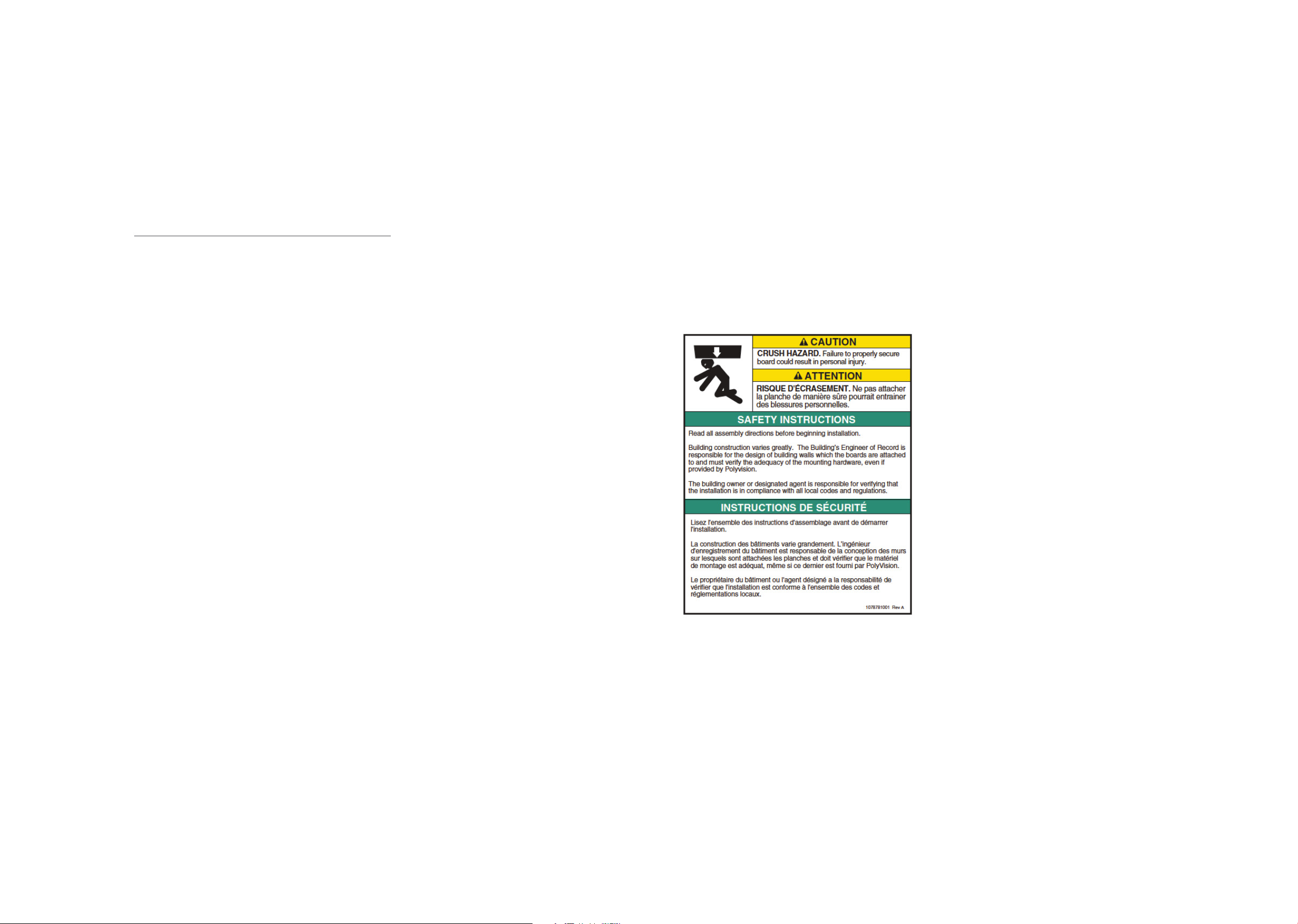
Safety Requirements
English
3 Safety Requirements
4 Handling + Storing of Panels
5 Required Materials + Equipment
6 Key to System Details
7 Standard Extrusions
8 D1 - D4 Systems
12 Installation
18 Warranty
Safety Requirements
a3 CeramicSteel Flow - Wall Mounted Dry Erase
Board, Non-Seismic Applications
The building’s Engineer of Record must be
consulted to determine if there are any seismic
requirements.
Verify Wall Construction
CAUTION! Adequate wall construction is
required to support the weight of the board.
Minimum wall construction must be capable
of supporting weight amounts listed in Table
1 on page 12.
Minimum Required Wall Construction
Drywall with metal studs:
• Must be at least 0.6 mm (.02”) thick Metal
stud 48.8 mm x 50 mm (1.92” x 1.97”)
• Studs on maximum 600 mm (24”) centers
• Must be at least 2 x 12,5 mm (.49”) Type X
gypsum drywall
• 35 mm (1.34”) drywall screws on 250 mm
(12”) centers
Drywall with wooden studs:
• Stud grade SPF, DFL or Hem-Fir 45 mm
x 70 mm (1.5” x 3.5”)
• Studs on 600 mm (24”) centers
• Must be atleast 25 mm (5/8”) thick Type X
gypsum drywall for the US or 2 x 12,5 mm (1/2”)
for EU
• 35 mm (#6 x 11/4”) drywall screws on 250 mm
(12”) centers
Doc # 81816 | Rev C | Page 2 of 56 Doc # 81816 | Rev C | Page 3 of 56

Handling + Storing of Panels
Required Materials + Equipment
Handling + Storing of Panels
Handling
• When a3 CeramicSteel panels are shipped, they
are protected by craft paper or a self-adhesive
transparent polyethylene ilm. Keep panels in the
original package until installation.
• Handle with care to prevent damage.
• Never slide panels o the stack during handling.
Panels should always be lifted and moved in a
vertical position.
• Never place an a3 panel in a vertical position on
the loor. This is to prevent damage to the edges.
• Prevent dirt from settling on and between panels
to avoid surface damage, scratches or defects.
• Follow all safety instructions regarding personal
protection when processing the panels.
• Protect panel surface against sawdust and
sparks (metal particles).
• a3 CeramicSteel will chip when cut or drilled with
power tools. Hand-cutting can cause chipping
up to approx. 2 mm from the edge. When
chipping is in excess of 2 mm, please check the
state of cutting tools and check that the panel is
adequately supported and clamped to prevent it
from vibrating.
• All cut or drilled sections should be protected
against humidity with PVC tape and/or by
covering/sealing proiles or sealing washers.
• For detailed processing instructions, please refer
to the a3 processing instructions.
Storing
• Keep panels dry and free of debris.
• Store panels inside temps 5090 °F (1032 °C).
• Any panels stored outside should be protected
from inclement weather conditions.
• Place panels on hard, lat surfaces that are not
subject to standing water.
• a3 CeramicSteel panels should be stacked no
more than three high.
• Panels should never be stored vertically or in
such a way that the corners are vulnerable to
damage.
If you have a problem, question, or a request, call
your local fabricator, your regional sales manager
or PolyVision Customer Service. PolyVision’s global
customer service team can be contacted on
polyvision.com.
Required Materials + Equipment
Electrical Equipment
1. Drill
2. Miter saw
3. Grinder
4. Jigsaw
5. Industrial vacuum cleaner
Hardware Equipment
1. Level (laser level recommended)
2. Aluminum straight guide
3. Chalk line
4. Anchors adapted to wall
• For gypsum walls, use #8 plastic wall anchor with #8 x 11/4” (4 mm x 35 mm) self drilling screws.
• For stone walls, anchors and screws must be provided by installer per conditions
• Recommended anchor spacing is 406 mm (16”) to 610 (24”) on center
5. Shims 1 mm - 2 mm - 3 mm (1/32” - 1/16” - 1/8”)
6. Soft wood block ± 50 mm x 25 mm x 300 mm (2” x 1” x 12”) length or rubber mallet to knock in the coverstrip
7. Glass suction cup lifters (2)
Included Hardware
1. Anchors
2. Screws
Doc # 81816 | Rev C | Page 4 of 56 Doc # 81816 | Rev C | Page 5 of 56
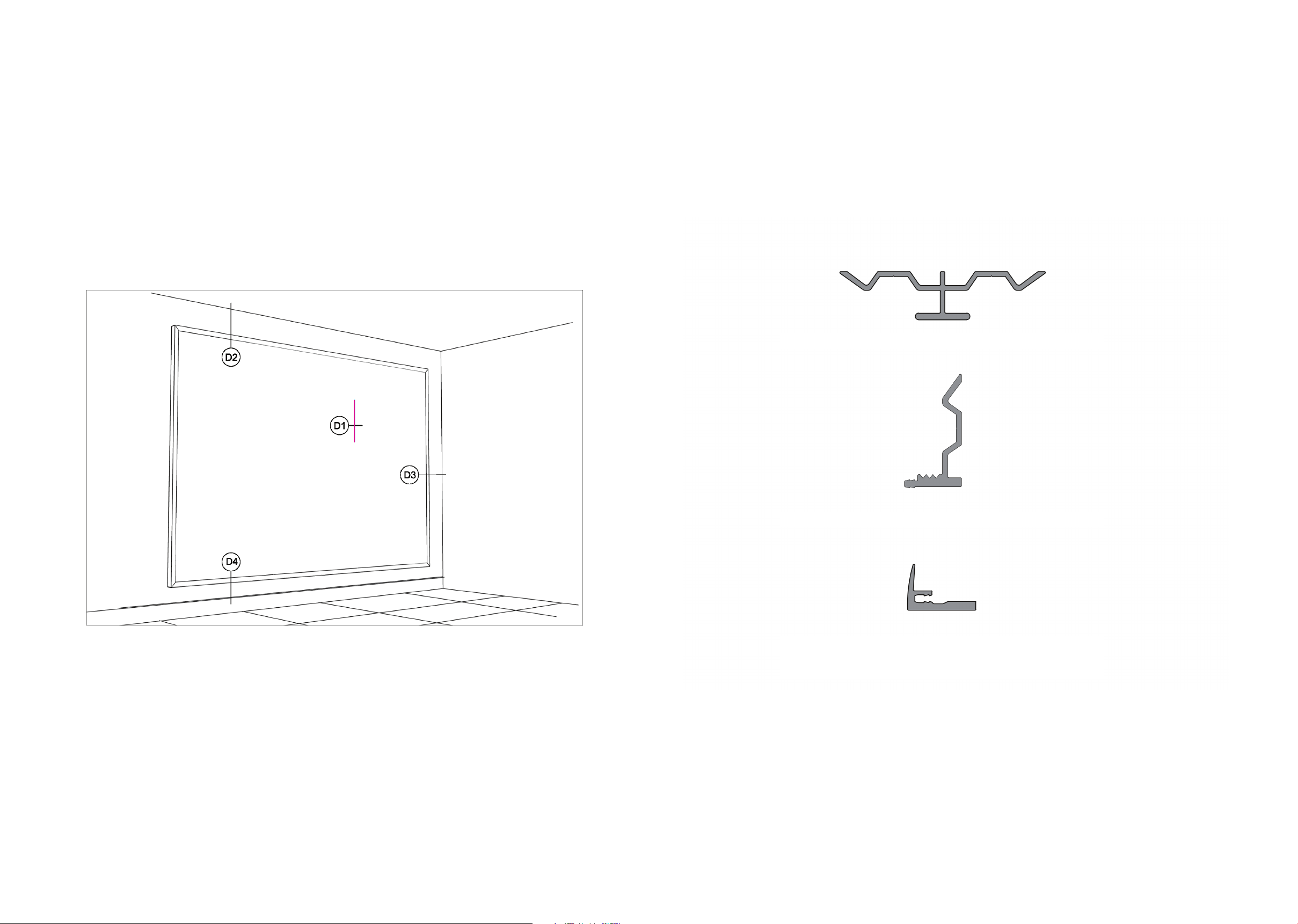
Key to System Details
Standard Extrusions
Key to System Details
The details listed in the image below show placement for panel proiles and how the material can be
installed. IMPORTANT: Proiles must be secured to studs in as many locations as possible and at least
24” o.c. for horizontals and 18” o.c. for verticals.
Standard Extrusions
Mid Frame
Base Frame
Top Frame
Doc # 81816 | Rev C | Page 6 of 56 Doc # 81816 | Rev C | Page 7 of 56
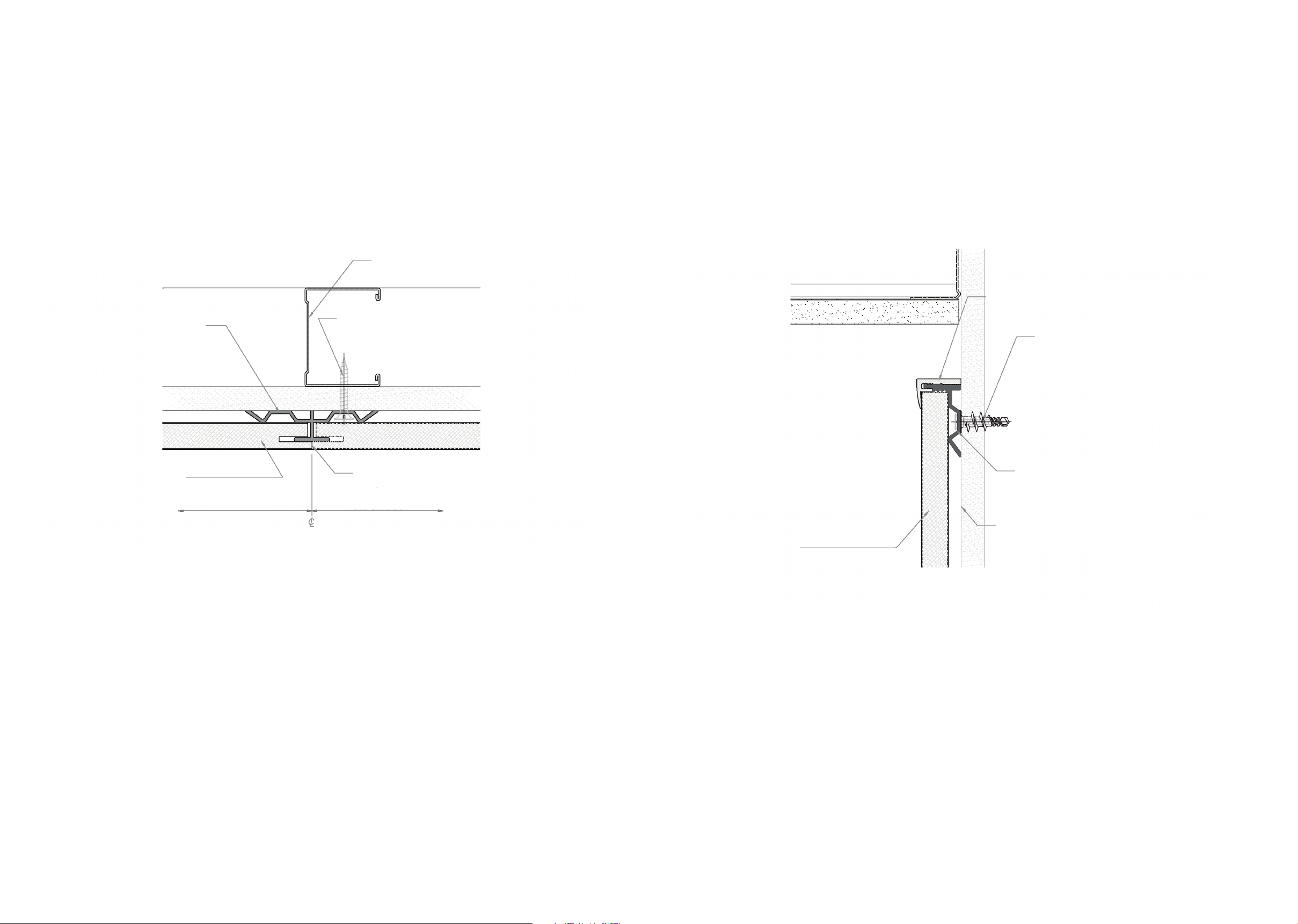
D1 - D4 Systems
D1 | Vertical Butt Joint D2 | Panel Head at Ceiling
structural support max
24” o.c. (by others)
mid
frame
type S bugle head screws
@ 16” o.c. (by erector)
top frame
gypsum board plug or screw
if located over stud
CeramicSteel
interior panels
panel dimension panel dimension
Grid
factory edges on both panels
CeramicSteel
interior panels
base frame
structural support max
24” o.c. (by others)
Doc # 81816 | Rev C | Page 8 of 56 Doc # 81816 | Rev C | Page 9 of 56
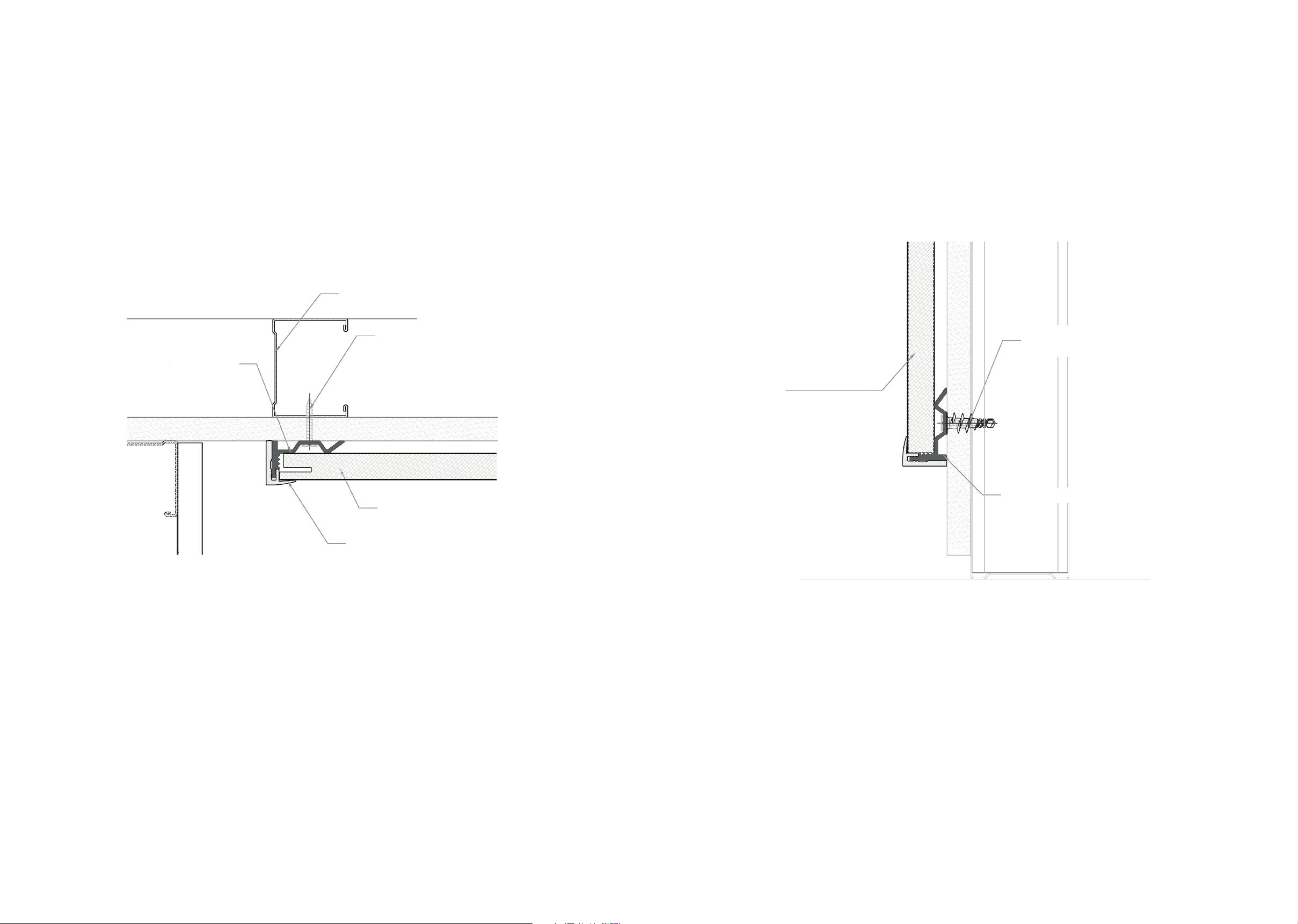
D3 | Panel Terminator at Wall D4 | Panel Bottom Line
structural support max
24” o.c. (by others)
base
rame
type S bugle head screws
@ 16” O.C. (by erector)
CeramicSteel
interior panels
top frame
gypsum board plug or
screw if located over stud
CeramicSteel
interior panels
base frame
Doc # 81816 | Rev C | Page 10 of 56 Doc # 81816 | Rev C | Page 11 of 56
Installation
Installation
Before starting the installation of a3 CeramicSteel Flow
1. Verify that the required equipment is available and material provided is accurate.
2. Provide adequate protection for inished loor surfaces.
3. If cutouts are required for electrical outlets or switches, refer to the following
instructions
• Square penetrations for light switches and electrical outlets can be made by
irst drilling a pilot hole and then cutting with a jig saw using a metal cutting
blade minimum 14 TPI (teeth per inch).
• All cutouts should be made with the inish side up, through the protective
Product Weight (kgs/lbs)
Flow 1830 28 kgs/61.7 lbs
Flow 2420 37 kgs/81.5 lbs
polyilm and a layer of common masking tape. Apply masking tape to the
entire area. Be sure to apply enough to protect the surface from the baseplate
of the saw.
• Metal burrs left after cutting can be removed with a ile or ine sand paper.
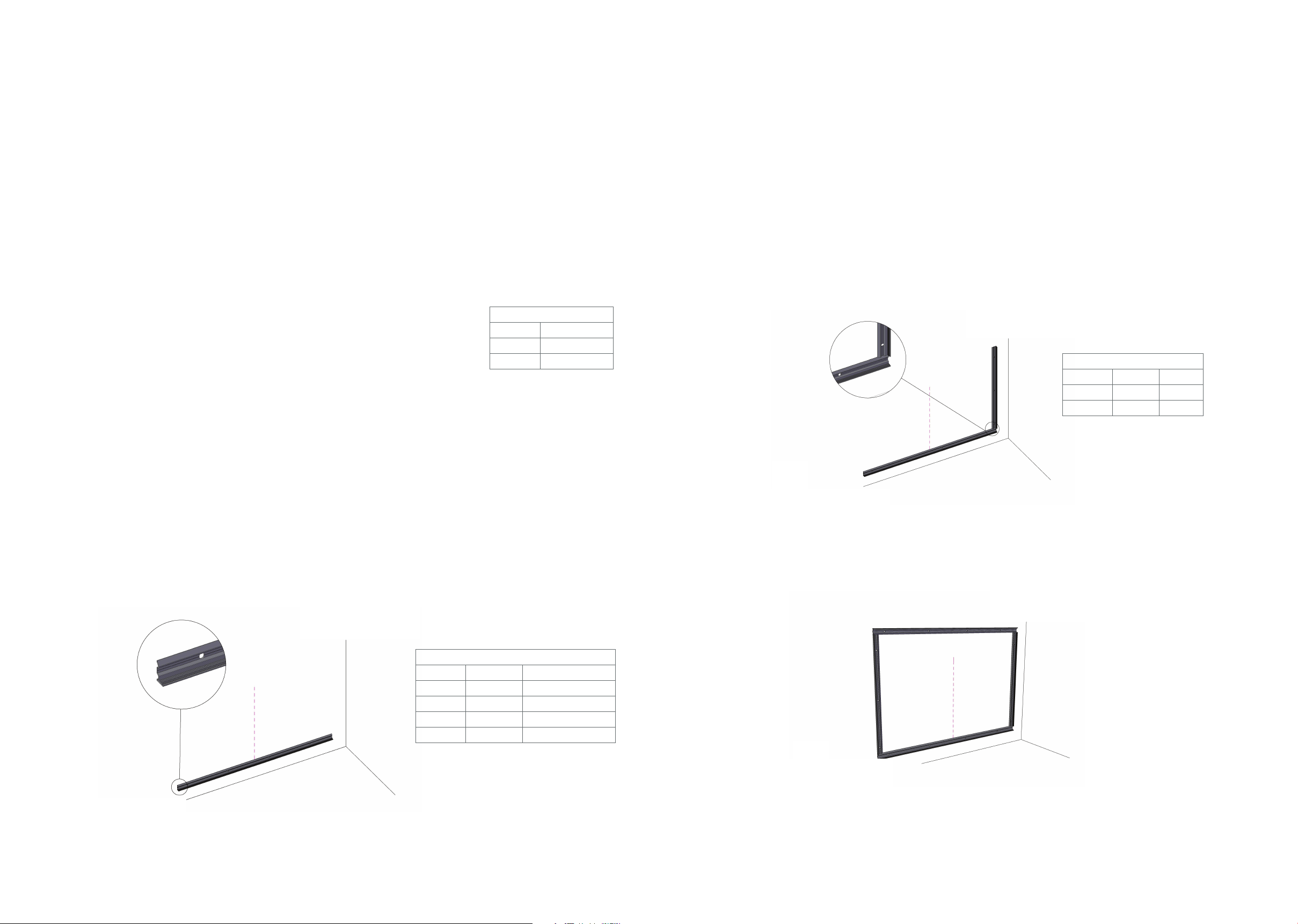
Step One
1. Start with a leveled line for the bottom proile. A laser level is recommended. Be sure to allow a
minimum of 3 mm (1/8”) space between the proile and the wall base molding.
2. Mark and drill the holes in the wall.
3. Attach the base frame using the provided anchors. Refer to Table 2 for proile dimensions.
Step Two
1. Start with a leveled line for the vertical proile (base frame). A laser level is recommended. Be sure to
allow a minimum of 3 mm (1/8”) space between the proile and any existing wall.
2. Mark and drill the holes in the wall.
Tab le 1
Vertical Trim Lengths
Product Inch mm
Flow 1830 69- 11/16 1770
Flow 2420 92- 7/8 2360
Step Three
1. Repeat steps 1 and 2 for top and adjacent base frames.
2. Mark and drill the holes in the wall
Tab le 2
Panel Qty Horizontal Proile
1 panel 2 1195 mm (47 1/16”)
2 panel 2 2380 mm (93 11/16”)
3 panel 2 3565 mm (140 5/16”)
4 panel 2 4750 mm (187”)
Doc # 81816 | Rev C | Page 12 of 56 Doc # 81816 | Rev C | Page 13 of 56
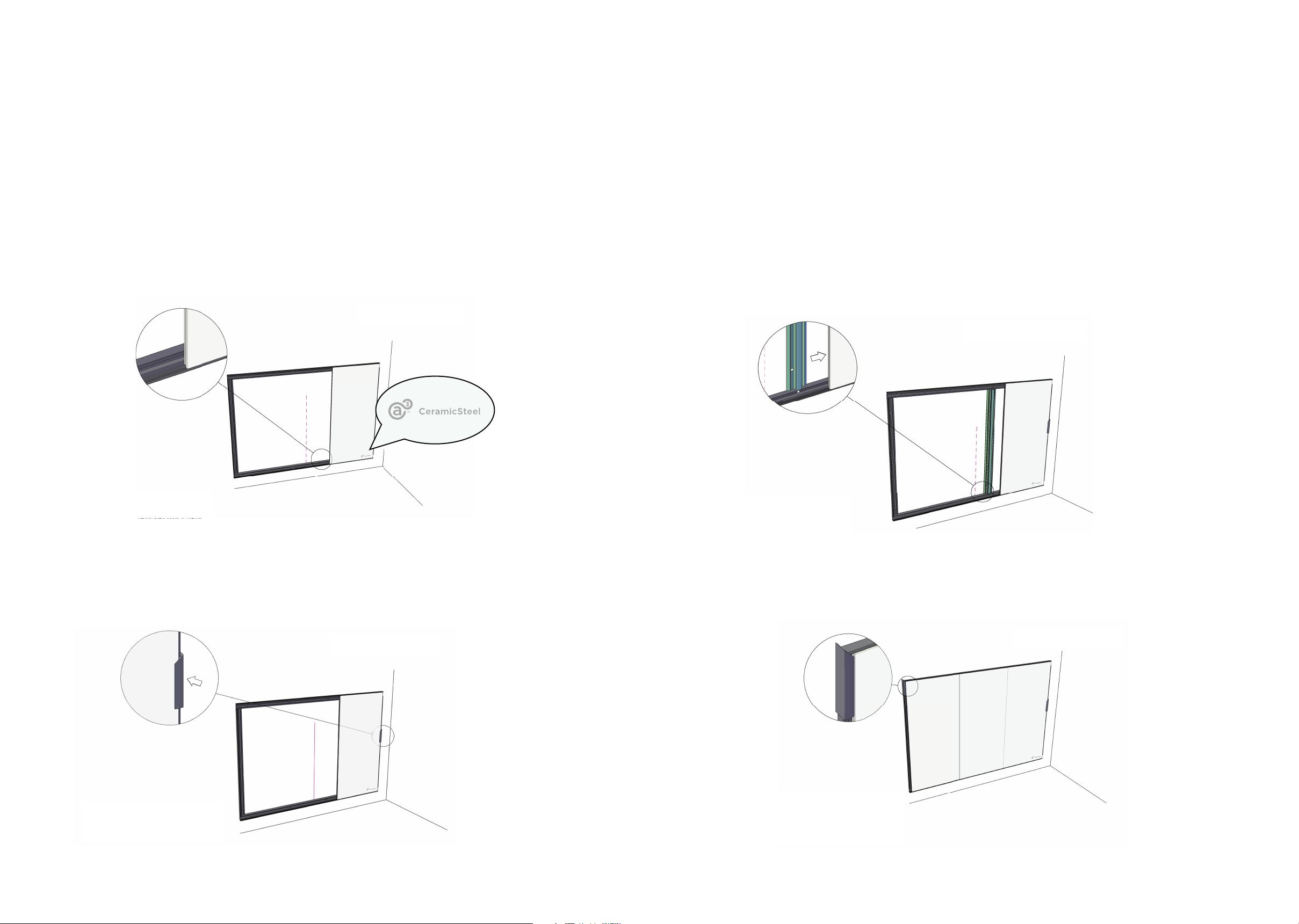
Installation
Step Four
1. Before installing the irst panel, locate the panel with the logo in the bottom right corner. (Note that the logo
is not drawn to size.) This panel will need to be the furthest right panel. This installation guide shows the
logo panel as the irst to be installed. Installation lows from right to left.
2. Place the irst panel (with logo) into position and hold the panel into position with a temporary piece of
cover trim 8” (200 mm). The panel must it against the vertical end proile and the horizontal bottom proile.
Cut pairs of Snap in Trim Extrusion, 8” (200mm) long with 45 mitre at one end. These can be used to
temporarily hold the irst panel until the Vertical Joint Spline is installed and secured.
Step Five
1. Insert the mid frame (H-proile) into the vertical side of the panel opposite from the vertical end
proile by sliding the metal extrusion into the groove on the side of the panel.
2. Depending upon the type of wall, either anchor directly through the lat part of the H-proile or
predrill the wall for the appropriate type of anchor.
Step Six
1. Repeat step 5 for the remaining panels
2. Place the inal panel into position and hold in place with a temporary piece of cover trim 8” (200 mm).
Doc # 81816 | Rev C | Page 14 of 56 Doc # 81816 | Rev C | Page 15 of 56
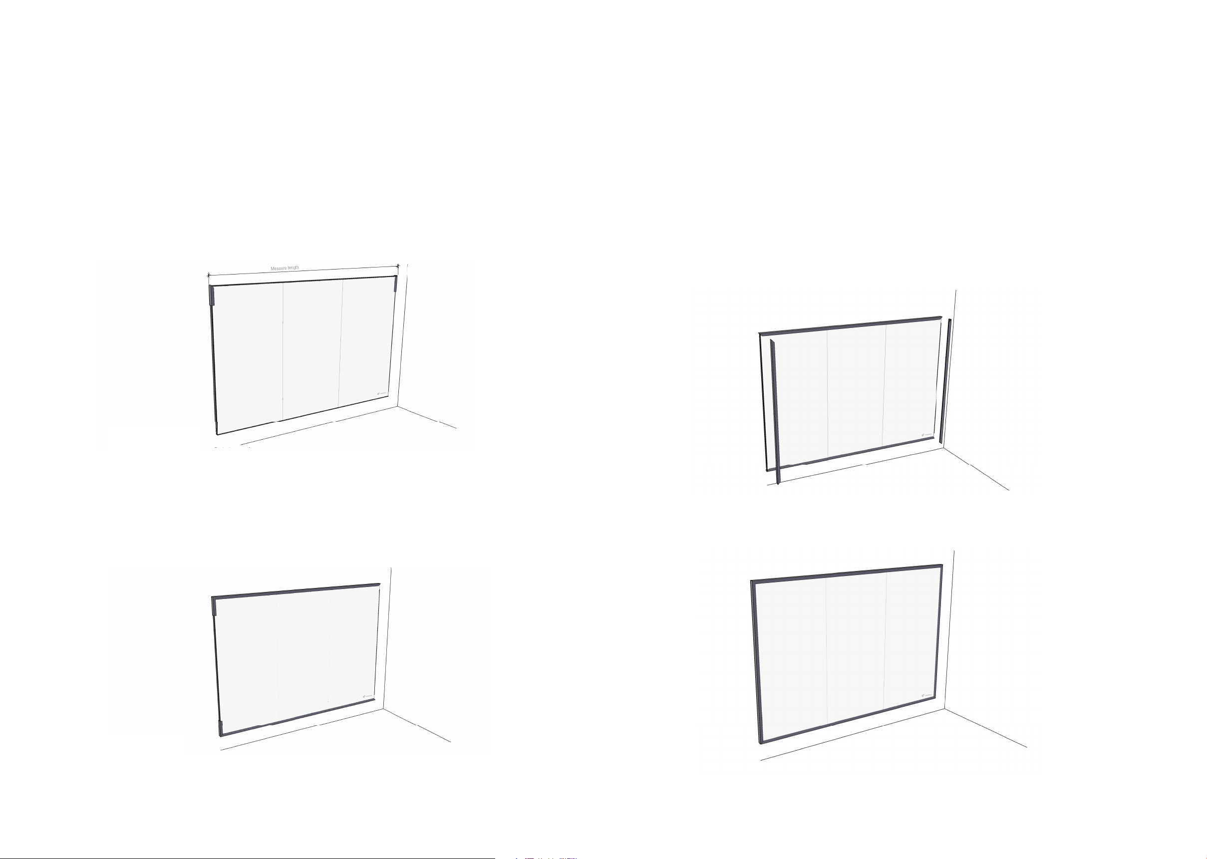
Installation
Step Seven
1. Place the temporary snap on cover trim pieces on each end of the verticals.
2. Measure and miter cut the top and bottom cover trim (top frame).
3. Place snap on cover trim being sure to install using a piece of soft wood blocking or a rubber mallet
in order to avoid damaging the exposed inish. Start the proile aligned with the bottom/top of the
panel. Once thenproiles are ixed they will be diicult to remove without damaging.
Step Eight
1. Measure and miter cut the vertical cover trim (top frame).
2. Place snap on cover trims being sure to install using a piece of soft wood blocking or a rubber mallet
in order to avoid damaging the exposed inish. Start the proile aligned with the panel. Once the
proiles are ixed they will be diicult to remove without damaging.
Step Nine
1. Installation for a3 CeramicSteel Flow is complete.
Doc # 81816 | Rev C | Page 16 of 56 Doc # 81816 | Rev C | Page 17 of 56
 Loading...