


a3 CERAMICSTEEL WORKWALL TECHNICAL GUIDE
PolyVision a3™ CeramicSteel Workwall maximizes the use of vertical space
while eliminating the need for multiple boards. A series of vertically oriented
whiteboard panels are spline jointed together and trimmed with an aluminum
extrusion on the “wall” outer edges. Floor-to-ceiling Workwall is a custom/special
order product. The following provides guidelines for installing your new system.

Safety Requirements
3
Handling + Storing Instructions
Required Equipment
Key to System Details
Standard Extrusions
D1 - D4 Systems
Installation
Limited International Warranty
4
5
6
7
8
12
19
2
polyvision.com
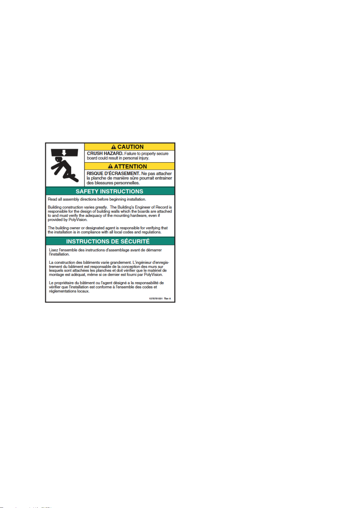
SAFETY REQUIREMENTS
a3 CeramicSteel Workwall - Wall Mounted Dry Erase Board, Non-Seismic Applications
The building’s Engineer of Record must be consulted to determine if there are any seismic requirements.
Verify Wall Construction
CAUTION: Adequate wall construction is required to support the weight of the board. Minimum wall
construction must be capable of supporting weight amounts listed in Table 1 on page 12.
Minimum Required Wall Construction
Drywall with metal studs:
• Must be at least 25 ga. (0.018” or .5 mm thk.)
33 ksi steel studs 38 mm x 89 mm (1.5” x 3.5”)
• Studs on maximum 610 mm (24”) centers
• Must be at least 16 mm (5/8”) thick Type X
gypsum drywall for the US or 12 mm (1/2”)
for EU
• 32 mm (#6 x 1-1/4”) drywall screws on
305 mm (12” ) centers
Drywall with wood studs:
• Stud grade SPF, DF-L, or Hem-Fir
38 mm x 89 mm (1.5” x 3.5”)
• Studs on 610 mm (24”) centers
• Must be at least 16 mm (5/8”) thick Type X
gypsum drywall for the US or 12 mm (1/2”)
for EU
• 32 mm (#6 x 1-1/4”) drywall screws on
305 mm (12” ) centers
polyvision.com
3
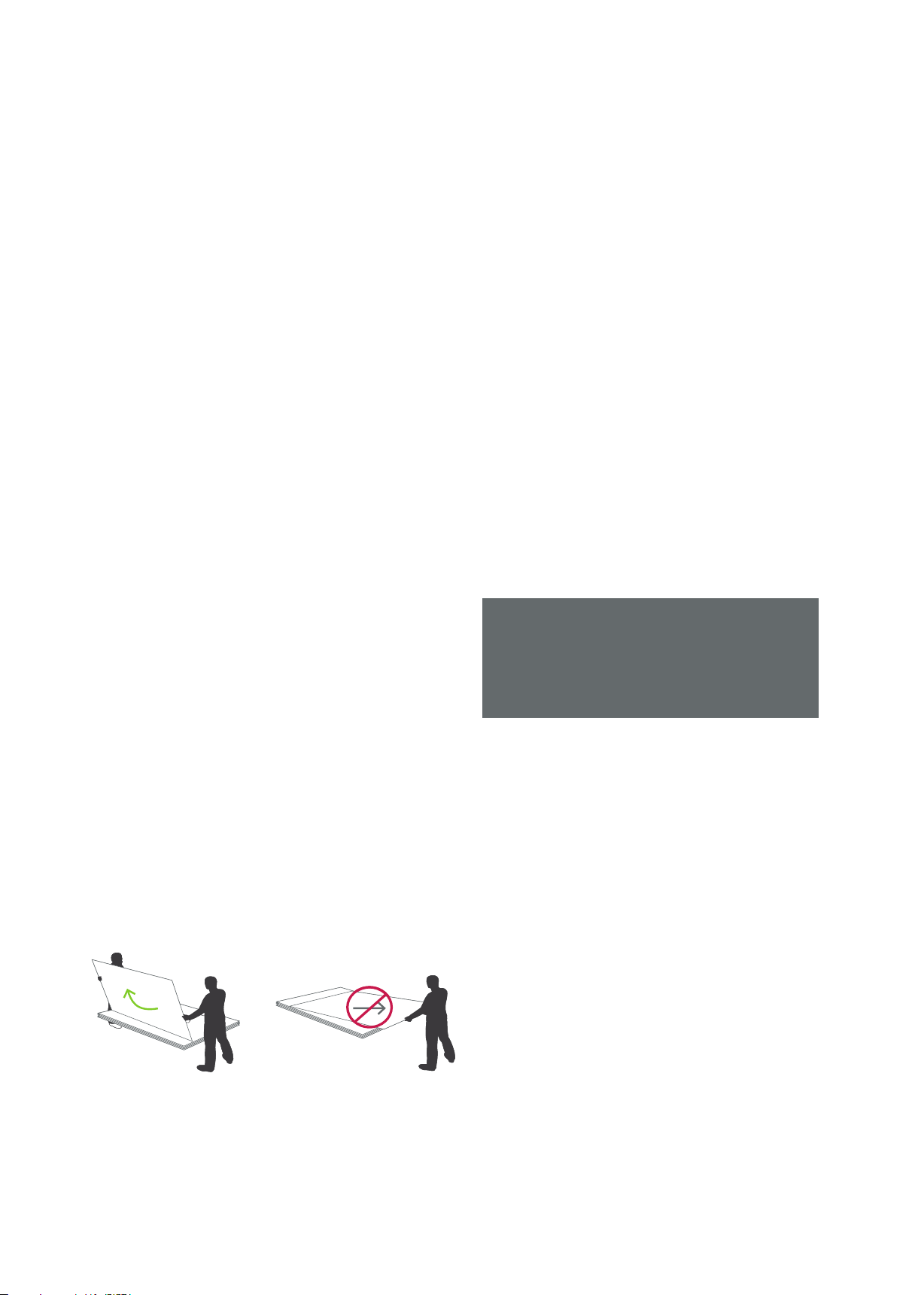
HANDLING + STORING OF PANELS
Handling
•
When a3 CeramicSteel panels are shipped, they are
protected by craft paper or a self-adhesive transparent
polyethylene film. Keep panels in the original package
until installation.
•
Handle with care to prevent damage.
•
Never slide panels off the stack during handling. Panels
should always be lifted and moved in a vertical position.
•
Never place an a3 panel in a vertical position on the
floor. This is to prevent damage to the edges.
•
Prevent dirt from settling on and between panels to avoid
surface damage, scratches or defects.
•
Follow all safety instructions regarding personal protection
when processing the panels.
Protect panel surface against sawdust and sparks
•
(metal particles).
•
a3 CeramicSteel will chip when cut or drilled with power
tools. Hand-cutting can cause chipping up to approx.
2 mm from the edge. When chipping is in excess of 2
mm, please check the state of cutting tools and check
that the panel is adequately supported and clamped to
prevent it from vibrating.
•
All cut or drilled sections should be protected against
humidity with PVC tape and/or by covering/sealing
profiles or sealing washers.
•
For detailed processing instructions, please refer to the
a3 processing instructions.
Storing
•
Keep panels dry and free of debris.
•
Store panels inside temps 50-90 °F (10-32 °C).
•
Any panels stored outside should be protected
from inclement weather conditions.
•
Place panels on hard, flat surfaces that are not
subject
to standing water.
•
a3 CeramicSteel panels should be stacked no more
than three high.
•
Panels should never be stored vertically or in such
a way that the corners are vulnerable to damage.
If you have a problem, question, or a request, call
your local fabricator, your regional sales manager
or PolyVision Customer Service. PolyVision’s
global customer service team can be contacted
on polyvision.com.
4
polyvision.com

REQUIRED EQUIPMENT
Electrical Equipment
1. Drill
2. Miter saw
3. Grinder
4. Jigsaw
5. Industrial vacuum cleaner
6. Panelsaw with guide
Hardware Equipment
1. Level (laser level recommended)
2. Aluminum straight guide
3. Chalk line
4. Anchors adapted to wall
• For gypsum walls, use #8 plastic wall anchor with #8 x 1-1/4” (4 mm x 35 mm) self drilling screws.
• For stone walls, anchors and screws must be provided by installer per conditions.
• Recommended anchor spacing is 406 mm (16”) to 610 mm (24”) on center
5. Shims 1 mm - 2 mm - 3 mm (1/32” - 1/16” - 1/8”)
6. Soft wood block ± 50 mm x 25 mm x 300 mm (2” x 1” x 12”) length or rubber mallet to knock in the coverstrip
7. Glass suction cup lifters (2)
8. New and unused cemented carbide (tungsten carbide, titanium carbide...) saw blade with a minimum of 60 teeth
9. Scrap lumber
Included Hardware
1. Anchors
2. Screws
3. Temporary cover trims (2)
polyvision.com
5
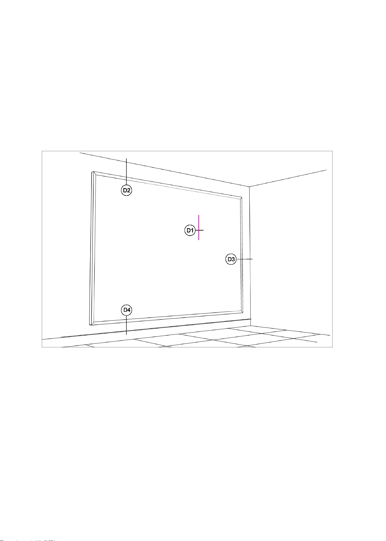
KEY TO SYSTEM DETAILS
The details listed in the image below show placement for panel profiles and how the material can be installed.
IMPORTANT: Profiles must be secured to studs in as many locations as possible and at least 24” o.c. for
horizontals and 18” o.c. for verticals.
6
polyvision.com

STANDARD EXTRUSIONS
509825 Joint spline extrusion
509821 End stop spline extrusion
509822 Snap in trim extrusion (clear anodized)
polyvision.com
7

D1
VERTICAL BUTT JOINTS
structural support max
24” o.c. (by others)
509825
extrusion
CeramicSteel
interior panels
type S bugle head screws
@ 16” o.c. (by erector)
factory edges on both panels
panel dimension panel dimension
Grid
8
polyvision.com

D2
PANEL HEAD AT CEILING
509822 anodized extrusion
gypsum board plug or
screw if located over stud
CeramicSteel
interior panels
509821
structural support max
24” o.c. (by others)
extrusion
polyvision.com
9

D3
PANEL TERMINATOR AT WALL
509821
extrusion
structural support max
24” o.c. (by others)
type S bugle head screws
@ 16” O.C. (by erector)
CeramicSteel
interior panels
509822 anodized extrusion
10
polyvision.com

D4
PANEL BOTTOM LINE
CeramicSteel
interior panels
gypsum board plug or
screw if located over stud
509821 extrusion
polyvision.com
11

INSTALLATION
Height - 3/8” (9 mm)
Before starting the installation of a3 CeramicSteel Workwall
1. Verify that the required equipment is available and material provided is accurate.
2. Provide adequate protection for finished floor surfaces.
3. If cutouts are required for electrical outlets or switches, refer to the following instructions.
• Square penetrations for light switches and electrical outlets can be made
by first drilling a pilot hole and then cutting with a jig saw using a metal
cutting blade minimum 14 TPI (teeth per inch).
• All cutouts should be made with the finish side up, through the protective
polyfilm and a layer of common masking tape. Apply masking tape to
the entire area. Be sure to apply enough to protect the surface from the
baseplate of the saw.
• Metal burrs left after cutting can be removed with a file or fine sand paper.
TABLE 1
Product Weight (kgs/lbs)
Workwall
183 0
Workwall
2420
28 kgs/61.7 lbs
37 kgs/81.5 lbs
Step One
1. Your panels will likely need to be cut to fit the wall. Make an accurate measurement of the area you want to
cover with the panels, mark the height and width of the final workwall surface.
Width
Height
2. Sketch the panel arrangement. Panel height should be the wall height less 3/8” (9 mm). Each panel provided
is 46 5/8” (1185 mm) wide. The final total width of all panels should be the wall width less 3/8” (9 mm).
Width - 3/8” (9 mm)
Width
12
Height
polyvision.com

INSTALLATION
3. The panels must be cut according to this arrangement. When cutting the panels, use a panelsaw
with guide equipped with a new, unused cemented carbide saw blade. Place the panel on scrap
wood at least 1” (25 mm) thick with the CeramicSteel (smooth side) facing down. Cut the panel using
the saw guide penetrating the scrap wood beneath approximately ¼” (6 mm).
CeramicSteel Face
¼” (6 mm) penetration
CeramicSteel Panel
Scrap Wood
Step Two
1. Start with a leveled line for the bottom profile. A laser level is recommended. Be sure to allow a
minimum of 3 mm (1/8”) space between the profile and the wall base molding.
2. Mark and drill the holes in the wall.
3. Attach the profile (509821) using the provided anchors. Refer to Table 2 for profile dimensions.
TABLE 2
Panel Qty Horizontal Profile
1 panel 2 1195 mm (47 1/16”)
2 panel 2 2380 mm (93 11/16”)
3 panel 2 3565 mm (140 5/16”)
4 panel 2 4750 mm (187”)
polyvision.com
13

INSTALLATION
Step Three
1. Start with a leveled line for the vertical profile. A laser level is recommended. Be sure to allow a
minimum of 3 mm (1/8”) space between the profile and any existing wall.
2. Mark and drill the holes in the wall.
Step Four
1. Repeat steps 1 and 2 for top and adjacent vertical profiles.
2. Mark and drill the holes in the wall.
14
polyvision.com

INSTALLATION
Step Five
1. Before installing the first panel, locate the panel with the logo in the bottom right corner. (Note
that the logo is not drawn to size.) This panel will need to be the furthest right panel. This
installation guide shows the logo panel as the first to be installed. Installation Workwalls from
right to left.
2. Place the first panel (with logo) into position and hold the panel into position with a temporary
piece of cover trim 8” (200 mm). The panel must fit against the vertical end profile and the
horizontal bottom profile.
polyvision.com
15

INSTALLATION
Step Six
1. Insert the H-profile (509825) into the vertical side of the panel opposite from the vertical end profile by
sliding the metal extrusion into the groove on the side of the panel.
2. Depending upon the type of wall, either anchor directly through the flat part of the H-profile or predrill
the wall for the appropriate type of anchor.
Step Seven
1. Repeat step 5 for the remaining panels.
2. Place the final panel into position and hold in place with a temporary piece of cover trim 8” (200 mm).
16
polyvision.com

INSTALLATION
Step Eight
1. Place the temporary snap on cover trim pieces on each end of the verticals.
2. Measure and miter cut the top and bottom horizontal cover trim (509822).
3. Place snap on cover trim being sure to install using a piece of soft wood blocking or a rubber mallet in order
to avoid damaging the exposed finish. Start the profile aligned with the bottom/top of the panel. Once the
profiles are fixed they will be difficult to remove without damaging.
polyvision.com
17

INSTALLATION
Step Nine
1. Measure and miter cut the vertical snap on cover trim (509822).
2. Place snap on cover trims being sure to install using a piece of soft wood blocking or a rubber mallet in
order to avoid damaging the exposed finish. Start the profile aligned with the panel. Once the profiles are
fixed they will be difficult to remove without damaging.
Step Ten
1. Installation for a3 CeramicSteel Workwall is complete.
18
polyvision.com

LIMITED INTERNATIONAL WARRANTY
Surfaces and Architectural Panels have a limited warranty for 20 and 10 years, respectively,
valid from the date of shipment. The limited warranty provides that the products, under normal
atmospheric conditions and when sealed from moisture, will not fade, stain, discolor, craze,
crack, flake, corrode or delaminate from the substrate or warp for the applicable period. Please
see the full PolyVision a3 CeramicSteel Surfaces and Architectural Panels: Limited International
Warranty for specific details, applicability and limitations.
Warranty effective 08.01.2011
polyvision.com
19

PolyVision Americas
10700 Abbotts Bridge Rd.
Suite 10 0
Johns Creek, GA 30097 USA
Tel. 1-888-325-6351
info@polyvision.com
PolyVision Europe
Zuiderring 56
3600 Genk, Belgium
Tel. +32 (0) 89 32 31 30
EMEAsupport@polyvision.com
©2017 PolyVision Corporation. All rights reserved. Trademarks used herein are the property
of PolyVision Corporation or of their respective owner. PolyVision Corporation reserves the
right to make chang es in prod uct design, cons truction or detail, and to discontinu e any
product or material without notice. No part of this document may be reproduced, transmitted,
transcribed, stored in a retrieval system, or translated into any language in any form by any means
without prior written permission from PolyVision.
11- 0 9 -17 EN G
PolyVision Asia-Pacific
15th Floor, Kinwick Centre
32 Hollywood Road, Central District
Hong Kong
Tel. +852 2520 0160
APACsupport@polyvision.com
 Loading...