


Kaskadierbare Einkabellösung
Typ: SCA 32
Einkabelanwendung (SCR / dCSS)
Inhaltsverzeichnis:
1 Überblick 1
2 Beschreibung 2
3 Anwendungsbeispiele 3
3.1 32 SCR-/dCSS-Teilnehmer/-Receiver am [Output 1] -> „FLEX Anwendung“ 3
3.2 32 wählbare Transponder am [Output 1] -> „FIX Anwendung“ (Kopfstellen-Modus) 4
3.3 Je 16 SCR-/dCSS-Teilnehmer/-Receiver am [Output 1] und/oder [Output 2] 5
3.4 Weitere Konfigurationsmöglichkeiten 6
3.5 Zusätzliche Optionen und Einstellungen 7
3.6 Programmiergerät für SCA 32 9
4 Empfehlungen für eine optimierte Funktionsweise 10
5 Installationsplan 11
6 Technische Daten 12
7 Montage und Sicherheitshinweise 13
1 Überblick
Anschlüsse:
Eingänge 4 x Sat-ZF-Eingänge vom Quattro-LNB
1 x UHF/VHF-Eingang für terrestrische Antennen
Ausgänge 4 x Sat-ZF-Durchschleif-Ausgänge
1 x Terrestrischer Durchschleif-Ausgang
1 x SCR-/dCSS-Ausgang [Output 1] mit max.32 Kanälen inkl. terr. Signal
1 x Universal-Ausgang [Output 2] mit kombiniertem terrestrischem Signal
Lieferumfang:
SCA 32
Stecker-Netzteil
DC-Einspeiseweiche
Abschlusswiderstände
Kurzanleitung
Bedienungsanleitung
0901809
1

2 Beschreibung
Der SCA 32 von Polytron ist eine SCR-/dCSS-Einkabellösung mit mehreren
Anwendungsmöglichkeiten.
Polytron-Art.-Nr.: 5903540 - Anwendung „FLEX“ - bis zu 32 Teilnehmer - Betriebsmodus: Dynamisch
Zum einen kann das Gerät als dynamische SCR-/dCSS-Lösung (SCA 32 Flex) mit Direktzugriffen von
bis zu 32 Teilnehmern/Receivern auf alle angeschlossenen Sat-Ebenen, und somit auch auf die
komplette Programmvielfalt, eingesetzt werden. Die Kommunikation zwischen dem Gerät und den
angeschlossenen Receivern erfolgt nach EN50494 und/oder EN50607 und kann separat je
Ausgangskanal definiert werden. Dies ermöglicht Installationen bestehend aus sowohl nur EN50494fähigen oder EN50607-kompatiblen Empfängern. Die verwendeten Receiver müssen diese
Steuerungsprotokolle unterstützen.
Polytron-Art.-Nr.: 5903541 - Anwendung „FIX“ - bis zu 32 Transponder - Betriebsmodus: Statisch
Zum anderen kann das Gerät als Mini-Kopfstelle (SCA 32 Fix) mit bis zu 32 fest eingestellten
Transpondern und Zugriff von unbegrenzt vielen Teilnehmern/Receivern angewendet werden.
Es lassen sich alle handelsüblichen digitalen Receiver (DVB-S und DVB-S2) einsetzen, d.h. es
werden keine speziellen SCR-/dCSS-Receiver zum Empfang benötigt.
Die Betriebsmodi (z.B. dynamisch oder statisch), die Kanalbandbreite, die Anzahl der Kanäle, die
Zwischenfrequenzen und ein Antennenjustage-Modus können mittels eines Programmiergerätes* vor
Ort konfiguriert und aktualisiert werden.
*Der SCA Programmer ist optional unter der Polytron-Art.-Nr.: 5903545 erhältlich.
Als erweiterten Service bieten wir Ihnen auch individuell vorprogrammierte Geräte an.
Bitte kontaktieren Sie uns, gerne unterbreiten wir Ihnen ein individuelles Angebot.
2
3 Anwendungsbeispiele
Ausgang/Output 1 =
32 x SCR-/dCSS-Receiver
Ausgang/Output 2 =
1 x Receiver
Kanal Standard SCR dCSS Frequenz
1 EN50494 & EN50607 UB 1 UB 1 1210MHz
2 EN50494 & EN50607 UB 2 UB 2 1420MHz
3 EN50494 & EN50607 UB 3 UB 3 1680MHz
4 EN50494 & EN50607 UB 4 UB 4 2040MHz
5 EN50494 & EN50607 UB 5 UB 5 984MHz
6 EN50494 & EN50607 UB 6 UB 6 1020MHz
7 EN50494 & EN50607 UB 7 UB 7 1056MHz
8 EN50494 & EN50607 UB 8 UB 8 1092MHz
9 EN50607 UB 9 1128MHz
10 EN50607 UB 10 1164MHz
11 EN50607 UB 11 1256MHz
12 EN50607 UB 12 1292MHz
13 EN50607 UB 13 1328MHz
14 EN50607 UB 14 1364MHz
15 EN50607 UB 15 1458MHz
16 EN50607 UB 16 1494MHz
17 EN50607 UB 17 1530MHz
18 EN50607 UB 18 1566MHz
19 EN50607 UB 19 1602MHz
20 EN50607 UB 20 1638MHz
21 EN50607 UB 21 1716MHz
22 EN50607 UB 22 1752MHz
23 EN50607 UB 23 1788MHz
24 EN50607 UB 24 1824MHz
25 EN50607 UB 25 1860MHz
26 EN50607 UB 26 1896MHz
27 EN50607 UB 27 1932MHz
28 EN50607 UB 28 1968MHz
29 EN50607 UB 29 2004MHz
30 EN50607 UB 30 2076MHz
31 EN50607 UB 31 2112MHz
32 EN50607 UB 32 2148MHz
Vorprogrammierung ab Werk
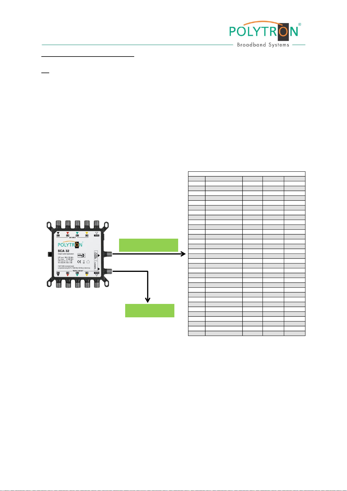
3.1 32 Teilnehmer/Receiver am SCR-/dCSS-Ausgang (Output 1) – Anwendung „FLEX“
Quattro-LNB mit den 4 Sat-ZF-Eingängen verbinden
(Quad-LNBs mit integriertem Schalter können nicht verwendet werden).
Eine ggf. vorhandene terrestrische Antenne mit dem UHF/VHF-Eingang verbinden.
Vorhandene(n) SCR-/dCSS-Receiver mit [Output 1] verbinden.
Bei Bedarf einen zusätzlich vorhandenen Receiver mit [Output 2] verbinden.
Für den Kaskaden-Betrieb das weiterführende Gerät mit den 4 Sat-ZF-Ausgängen und ggf.
mit dem terrestrischen Ausgang verbinden (das terrestrische Signal wird dabei nicht
verstärkt).
Die beiliegenden Abschlusswiderstände auf die Durchschleif-Ausgänge aufschrauben, falls
das Gerät nicht im Kaskaden-Betrieb verwendet wird, um einen optimalen Betrieb zu
gewährleisten.
Darstellung der Konfiguration „FLEX“
Werkseinstellung
3

3.2 32 ausgewählte Transponder am [Output 1] – Anwendung „FIX“
Ausgang/Output 1 =
32 Transponder nach Wahl
Ausgang/Output 2 =
1 x Receiver
Quattro-LNB mit den 4 Sat-ZF-Eingängen verbinden
(Quad-LNBs mit integriertem Schalter können nicht verwendet werden).
Eine ggf. vorhandene terrestrische Antenne mit dem UHF/VHF Eingang verbinden.
Vorhandene(n) Receiver mit [Output 1] verbinden.
Bei Bedarf einen zusätzlich vorhandenen Receiver mit [Output 2] verbinden.
Für den Kaskaden-Betrieb das weiterführende Gerät mit den 4 Sat-ZF-Ausgängen und ggf.
mit dem terrestrischen Ausgang verbinden (das terrestrische Signal wird dabei nicht
verstärkt).
Die beiliegenden Abschlusswiderstände auf die Durchschleif-Ausgänge aufschrauben, falls
das Gerät nicht im Kaskaden-Betrieb verwendet wird, um einen optimalen Betrieb zu
gewährleisten.
Darstellung der Konfiguration „FIX“
4

3.3 Je 16 SCR-/dCSS-Teilnehmer/-Receiver am [Output 1] und/oder [Output 2]
Ausgang/Output 1 =
16 x SCR-/dCSS-Receiver
Ausgang/Output 2 =
16 x SCR-/dCSS-Receiver
Kanal Standard SCR dCSS Frequenz
1 EN50494 & EN50607 UB 1 UB 1 1210MHz
2 EN50494 & EN50607 UB 2 UB 2 1420MHz
3 EN50494 & EN50607 UB 3 UB 3 1680MHz
4 EN50494 & EN50607 UB 4 UB 4 2040MHz
5 EN50494 & EN50607 UB 5 UB 5 984MHz
6 EN50494 & EN50607 UB 6 UB 6 1020MHz
7 EN50494 & EN50607 UB 7 UB 7 1056MHz
8 EN50494 & EN50607 UB 8 UB 8 1092MHz
9 EN50607 UB 9 1128MHz
10 EN50607 UB 10 1164MHz
11 EN50607 UB 11 1256MHz
12 EN50607 UB 12 1292MHz
13 EN50607 UB 13 1328MHz
14 EN50607 UB 14 1364MHz
15 EN50607 UB 15 1458MHz
16 EN50607 UB 16 1494MHz
17 EN50607 UB 17 1530MHz
18 EN50607 UB 18 1566MHz
19 EN50607 UB 19 1602MHz
20 EN50607 UB 20 1638MHz
21 EN50607 UB 21 1716MHz
22 EN50607 UB 22 1752MHz
23 EN50607 UB 23 1788MHz
24 EN50607 UB 24 1824MHz
25 EN50607 UB 25 1860MHz
26 EN50607 UB 26 1896MHz
27 EN50607 UB 27 1932MHz
28 EN50607 UB 28 1968MHz
29 EN50607 UB 29 2004MHz
30 EN50607 UB 30 2076MHz
31 EN50607 UB 31 2112MHz
32 EN50607 UB 32 2148MHz
Quattro-LNB mit den 4 Sat-ZF-Eingängen verbinden
(Quad-LNBs mit integriertem Schalter können nicht verwendet werden).
Eine ggf. vorhandene terrestrische Antenne mit dem UHF/VHF Eingang verbinden.
Bis zu 16 SCR-/dCSS-Teilnehmer/-Receiver mit [Output 1] verbinden.
Bis zu 16 SCR-/dCSS-Teilnehmer/-Receiver mit [Output 2] verbinden.
Für den Kaskaden-Betrieb das weiterführende Gerät mit den 4 Sat-ZF-Ausgängen und ggf.
mit dem terrestrischen Ausgang verbinden (das terrestrische Signal wird dabei nicht
verstärkt).
Die beiliegenden Abschlusswiderstände auf die Durchschleif-Ausgänge aufschrauben, falls
das Gerät nicht im Kaskaden-Betrieb verwendet wird, um einen optimalen Betrieb zu
gewährleisten.
Darstellung der Konfiguration „SCR-/dCSS x 16 + SCR-/dCSS x 16“
5

3.4 Folgende Konfigurationen sind möglich:
Satellite Channel Routing „FLEX Anwendung“ + Universal
Über [Output 1] können bis zu 32 Teilnehmer/Receiver direkt mit SCR-/dCSS-Signalen versorgt
werden. Der andere Ausgang [Output 2] arbeitet zeitgleich im Universal-Modus (siehe Punkt 3.1).
Die Kommunikation zwischen dem Gerät (SCA 32 Flex) und den angeschlossenen SCR-/dCSSReceivern erfolgt nach EN50494 und/oder EN50607. Die verwendeten Receiver müssen diese
Steuerungsprotokolle unterstützen.
Satellite Channel Routing („unabhängiger Ausgang“)
Jeder Ausgang [Output 1 & 2] kann eine unterschiedliche SCR-/dCSS-Konfiguration ausgeben.
An beiden Ausgängen können insgesamt bis zu 32 Teilnehmer/Receiver direkt mit SCR-/dCSSSignalen versorgt werden. Mit dieser Option lassen sich zwei unabhängig voneinander agierende
Einkabellösungen mit einem Gerät realisieren (siehe Punkt 3.3).
Satellite Channel Routing („gemeinsamer Ausgang“)
Bei dieser Konfiguration haben bis zu 32 Teilnehmer/Receiver an beiden Ausgängen
[Output 1 & 2] direkten Zugriff auf die gleichen SCR-/dCSS-Signale, diese können ohne
zusätzlichen Verteiler auf zwei getrennte Stammleitungen aufgeteilt werden.
Kopfstellen-Modus „FIX Anwendung“ + Universal
Beim Gerät (SCA 32 FIX) können über [Output 1] bis zu 32 fest eingestellte Transponder an
unbegrenzt viele Teilnehmer, bzw. Receiver ausgegeben werden, während der andere Ausgang
[Output 2] im Universal-Modus arbeitet (siehe Punkt 3.2). Es werden keine speziellen Receiver
zum Empfang benötigt.
Quattro-LNB am Eingang (1 Satellit)
Das Gerät wird zum Empfang von Quattro-LNB-Signalen konfiguriert. Es ist möglich, die
Ausgänge mehrerer SCA 32 mit Hilfe von HF-Combinern zusammenzuführen (verketten) und
dann jedem einzelnen Gerät den Empfang einer unterschiedlichen Satelliten-Position zuzuordnen.
Zum Beispiel kann man einer SCA 32 den Satellit A und einem anderen den Satellit B zuordnen.
Wenn nun der Receiver einen Kanal des Satelliten A anfordert, wird der erste SCA 32 den
entsprechenden Kanal bereitstellen, während der zweite diesen Kanal deaktiviert. Wenn der
Receiver dann einen Kanal des Satelliten B anfordert, wird der erste SCA 32 diesen Kanal
deaktivieren und der zweite diesen Kanal nun bereitstellen.
6

3.5 Zusätzliche Optionen und Einstellungen
„Normales“ (Universal-) Signal bei Inbetriebnahme im „FLEX-Modus“
Durch Aktivierung dieser Funktion wird bei Inbetriebnahme ein „normales“ (Universal-) Signal
ausgegeben. Nach Erhalt eines SCR-/dCSS-Befehls wird das Gerät dann wieder auf diesen
Modus geschaltet. Diese Option kann nützlich sein, wenn man die Sat-Antenne mit einem
Antennenmessgerät justieren möchte, welches die SCR-/dCSS-Standards nicht unterstützt.
dCSS Kanal-Nummerierung im „FLEX-Modus“
Nach Aktivierung dieser Option kann man die Nummerierung der Kanäle gemäß EN50607
ändern, wenn man eine andere Reihenfolge haben möchte.
7

Digitale Verstärkungseinstellung
Ausgehend vom Mittelwert -26 dBm (82 dBµV @ 75 Ω) kann die DAC-Dämpfung für jeden Kanal
separat eingestellt werden.
Dieser Wert kann je Kanal wie folgt verändert und mit Apply bestätigt werden:
Minimalwert: -29,75 dBm (79 dBµV @ 75 Ω)
Mittelwert: -26,00 dBm (82 dBµV @ 75 Ω)
Maximalwert: -22,00 dBm (86 dBµV @ 75 Ω)
Eine aktuelle Information zur möglichen Dämpfungseinstellung wird angezeigt, sobald der
Mauszeiger auf die Zeile eines Kanals bewegt wird (in diesem Beispiel auf Kanal 2).
Mithilfe dieser Einstellung können eventuelle Signalunterschiede kompensiert oder z.B. auch
installationsspezifische Verluste korrigiert werden.
8

3.6 Programmiergerät für SCA 32
Den 12V AC/DC-Adapter mit dem Spannungseingang des Programmiergerätes verbinden.
Das Programmiergerät über ein USB-Kabel mit dem PC verbinden.
Die PC-Software mittels Doppelklick auf Programmiergeräte-Icon auf dem PC-Startbildschirm
starten.
Eine aktuelle Konfiguration kann auch intern im Programmiergerät oder auf dem PC gespeichert
werden, um diese auf andere Geräte des Typs SCA 32 übertragen zu können. Einzelheiten hierzu
entnehmen Sie bitte der Bedienungsanleitung des Programmiergerätes.
9

4 Empfehlungen für eine optimierte Funktionsweise
Jedem Sat-Tuner wird eindeutig eine SCR-/dCSS-Empfangsfrequenz zugeordnet, bitte
notieren. Es muss sichergestellt sein, dass nicht zwei Receiver versehentlich die gleiche
Frequenz benutzen.
Doppeltuner benötigen die Zuweisung von zwei SCR-/dCSS-Frequenzen! Das Signal darf
nicht vom >Ausgang Tuner 1< auf >Eingang Tuner 2< durchgeschleift, sondern muss z.B. mit
einem 2-fach Verteiler (Polytron-Typ: FVS 2 P) aufgesplittet und an beide Tuner-Eingänge
direkt angeschlossen werden.
Dem Sat-Tuner mit der längsten Kabelstrecke sollte die niedrigste SCR-/dCSS-Frequenz
zugeordnet werden, dem Sat-Tuner mit der kürzesten Kabelstrecke die höchste Frequenz.
Wenn weniger als 32 Tuner verwendet werden, so sollten bevorzugt die niedrigen SCR-/
dCSS-Frequenzen benutzt werden.
Manche Receiver beginnen die SCR-/dCSS-Adressenzählung bei „0“. In diesem Fall muss bei
solchen Geräten entsprechend zurückgezählt werden.
Beispiel: entweder „0 bis 31“ oder „1 bis 32“.
Verwenden Sie für die Verbindungen zumindest doppelt geschirmte Kabel guter Qualität mit
einem Schirmungsmaß von min. 90dB.
Stellen Sie sicher, dass die verwendeten Antennendosen mit der SCR-/dCSS-Technologie
kompatibel sind und eine bidirektionale Signal-Übertragung ermöglichen.
Es wird mindestens ein DC-entkoppelter Abschlusswiderstand benötigt, wenn die SCA 32 in
einer Baumstruktur mit Durchgangsdosen eingesetzt wird. Als letzte Antennendose muss in
einem solchen Verteilsystem ebenfalls eine Durchgangsdose montiert werden. Diese wird mit
Hilfe eines DC-entkoppelten Abschlusswiderstandes (Polytron-Typ: AW 75 DC)
abgeschlossen.
Wir empfehlen die Nutzung der mitgelieferten Einspeiseweiche (Power Inserter) zur
Spannungsversorgung des LNBs und der SCA 32, denn damit ist eine stabile Funktionsweise
dieser Komponenten gewährleistet. Das mitgelieferte Steckernetzteil kann auch direkt über
[Output 2] angeschlossen werden, falls dieser Ausgang nicht benötigt wird. Die
Einspeiseweiche wird in diesem Fall dann nicht benötigt.
10

5 Installationsplan
Kanal /
Channel
Standard SCR dCSS Frequenz / Frequency Stockwerk / Floor Einbauort / Installation location
12345
6789101112
13141516171819
2021222324252627282930
3132Installationsplan / Installation schedule
11

6 Technische Daten
Lieferant POLYTRON
Typ SCA 32
Eingänge
4 x Satelliten-ZF-Eingänge vom Quattro-LNB
1 x UHF / VHF Eingang für terrestrische Antennen
Ausgänge
4 x Satelliten-ZF-Durchschleif-Ausgänge
1 x terrestrischer Durchschleif-Ausgang
1 x Legacy-Ausgang mit kombiniertem terrestrischem Signal
1 x SCR-/dCSS-Ausgang mit max. 32 UBs (Kanälen) und kombiniertem terr. Signal
Steuerungsprotokoll DiSEqC1.x / DiSEqC2.0, EN50494 (SCR) / EN50607 (dCSS)
Eingangsfrequenzbereiche Satellit: 950 - 2150 MHz / Terrestrik: 47 - 862 MHz
Durchschleifdämpfung Satellit und Terrestrik: je 3 dB max.
Konversionsgewinn SCR-/dCSS-Ausgang: -25 dB min. / Universal-Ausgang: -1 bis +7 dB
Ausgangssignalpegel (AGC-kontrolliert) Konfigurierbar (min. -25 dBm = 83 dBµV @ 75Ω)
Eingangssignalpegel -50 bis -15 dBm (58 - 93 dBµV @ 75Ω)
User Band (Kanal) Bandbreite Konfigurierbar, 10 - 80 MHz (Werkseinstellung: 36 MHz)
User Band (Kanal) Verstärkungswelligkeit 3 dB max.
User Band Frequenzen (Kanäle) Konfigurierbar, Werkseinstellung: 32 User Bands
HF Isolierung
Satellit / Satellit ZF 28 dB min.
Satellit / Terrestrik 28 dB min.
Satellitenkanal / Kanal (User Bands) 28 dB min.
LO Phasenrauschen
bei 1 kHz: -80 dBc/Hz max.
bei 10 kHz: -92 dBc/Hz max.
bei 100 kHz: -96 dBc/Hz max.
bei 1 MHz: -104 dBc/Hz max.
System-Phasenrauschen 1,5 Grad max.
Eingang / Ausgang VSWR 2,5 : 1
Eingangs- / Ausgangsimpedanz
75 Ohm (F-Type)
Universal-Ausgang Umschaltung
V/L => 13 V / 0 kHz
V/H => 13 V / 22 kHz
H/L => 18 V / 0 kHz
H/H => 18 V / 22 kHz
LNB-Stromzufuhr 13/18 V, 300 mA max.
DC-Stromaufnahme 450 mA max. bei 13 Vdc
Betriebstemperatur - 20 bis + 60 °C
Abmessungen 114 x 111 x 21 (H x B x T) mm
12

7 Montage und Sicherheitshinweise
13

Notizen / Notes:
14

Satellite Channel Router (SCR)
Type: SCA 32
Single Cable Application (SCR / dCSS)
Contents:
1 Overview 15
2 Description 16
3 Application examples 17
3.1 32 User Bands via [Output 1] -> „FLEX application“ 17
3.2 32 Transponders via [Output 1] -> „FIX application“ (Headend modus) 18
3.3 16 User Bands each via [Output 1] and [Output 2] 19
3.4 Further configurations 20
3.5 Additional options and settings 21
3.6 Programmer for SCA 32 23
4 Recommendations to optimize operation 24
5 Installation schedule 25
6 Technical data 26
7 Installation and safety instructions 27
1 Overview
Connections:
Inputs 4 x Satellite IF inputs from Quattro LNB
1 x UHF/VHF-input from terrestrial antenna
Outputs 4 x loop through satellite IF outputs
1 x loop through terrestrial output
1 x SCR/dCSS output [1] with up to 32 User Bands and combined terr. signal
1 x Universal output [2] with combined terrestrial signal
Accessoires:
SCA 32
AC/DC adapter
Power inserter device
Termination resistors
Short manual
0901809
User manual
15

2 Description
The SCA 32 from Polytron is a Satellite Channel Router (SCR/dCSS) enabling various application
possibilities.
Polytron-Art.-No.: 5903540 - „FLEX application“ – up to 32 User Bands - Modus: Dynamic
Firstly the device can work as a dynamic SCR-/dCSS-solution (SCA 32 Flex) with directly access to all
connected Sat-levels and thereby to the entire programme diversity for up to 32 users/receivers.
Polytron-Art.-No.: 5903541 – „FIX application“ – up to 32 Transponders - Modus: Static
On the other hand the device can be used as a mini-headend (SCA 32 Fix) with up to 32 fixed
configured transponders and access for an unlimited number of users/receivers.
The communication protocol between the device and the connected SCR/dCSS receivers is based on
EN50494 and/or EN50607 and can be defined per User Band allowing operators to support
installations consisting of both EN50494-only and EN50607. All connected receivers have to support
these control protocols.
The operation mode (e.g. dynamic or static), channel bandwidth, UB numbers, center frequencies and
the functionality of each of the output ports can all be programmed* as well.
* Programmer not included, sold separately as an optional accessory (Polytron-Art.-No.: 5903545).
As an extended service we can also offer you various preprogrammed devices.
Please don’t hesitate to contact us, we willingly submit you an individual offer.
16

3 Application examples
Output 1 =
32 x SCR/dCSS Receivers
Output 2 =
1 x Receiver
Channel Standard SCR dCSS Frequency
1 EN50494 & EN50607 UB 1 UB 1 1210MHz
2 EN50494 & EN50607 UB 2 UB 2 1420MHz
3 EN50494 & EN50607 UB 3 UB 3 1680MHz
4 EN50494 & EN50607 UB 4 UB 4 2040MHz
5 EN50494 & EN50607 UB 5 UB 5 984MHz
6 EN50494 & EN50607 UB 6 UB 6 1020MHz
7 EN50494 & EN50607 UB 7 UB 7 1056MHz
8 EN50494 & EN50607 UB 8 UB 8 1092MHz
9 EN50607 UB 9 1128MHz
10 EN50607 UB 10 1164MHz
11 EN50607 UB 11 1256MHz
12 EN50607 UB 12 1292MHz
13 EN50607 UB 13 1328MHz
14 EN50607 UB 14 1364MHz
15 EN50607 UB 15 1458MHz
16 EN50607 UB 16 1494MHz
17 EN50607 UB 17 1530MHz
18 EN50607 UB 18 1566MHz
19 EN50607 UB 19 1602MHz
20 EN50607 UB 20 1638MHz
21 EN50607 UB 21 1716MHz
22 EN50607 UB 22 1752MHz
23 EN50607 UB 23 1788MHz
24 EN50607 UB 24 1824MHz
25 EN50607 UB 25 1860MHz
26 EN50607 UB 26 1896MHz
27 EN50607 UB 27 1932MHz
28 EN50607 UB 28 1968MHz
29 EN50607 UB 29 2004MHz
30 EN50607 UB 30 2076MHz
31 EN50607 UB 31 2112MHz
32 EN50607 UB 32 2148MHz
Factory settings
3.1 32 User bands via output [1] – “FLEX” application
Connect the Quattro-LNB with the 4 Sat-IF-inputs
(Quad-LNBs with integrated switches can’t be used).
Where applicable connect the terrestrial antenna with the UHF/VHF input.
Connect existing SCR/dCSS receiver(s) with output [1].
As required connect an additional receiver with the output [2].
For cascade operation connect the continuing device with the 4 loop through satellite IF
outputs and, where applicable, with the terrestrial output (the terrestrial signal won’t be
amplified).
For optimal performances, the loop through outputs that are not used shall be terminated with
75 Ohm DC-decoupled terminating resistors.
Illustration of the “FLEX” configuration
Factory setting
17

3.2 32 transponders via output [1] – “FIX” application (Headend modus)
Output 1 =
32 Transponders as chosen
Output 2 =
1 x Receiver
Connect the Quattro-LNB with the 4 Sat-IF-inputs
(Quad-LNBs with integrated switches can’t be used).
Where applicable connect the terrestrial antenna with the UHF/VHF input.
Connect existing receiver(s) with the output [1].
As required connect an additional receiver with the output [2].
For cascade operation connect the continuing device with the 4 loop through satellite IF
outputs and, where applicable, with the terrestrial output (the terrestrial signal won’t be
amplified).
For optimal performances, the loop through outputs that are not used shall be terminated with
75 Ohm DC-decoupled terminating resistors.
Illustration of the “FIX” configuration
18

3.3 16 User Bands each via [Output 1] and [Output 2]
Output 1 =
16 x SCR/dCSS receivers
Output 2 =
16 x SCR/dCSS receivers
Kanal Standard SCR dCSS Frequenz
1 EN50494 & EN50607 UB 1 UB 1 1210MHz
2 EN50494 & EN50607 UB 2 UB 2 1420MHz
3 EN50494 & EN50607 UB 3 UB 3 1680MHz
4 EN50494 & EN50607 UB 4 UB 4 2040MHz
5 EN50494 & EN50607 UB 5 UB 5 984MHz
6 EN50494 & EN50607 UB 6 UB 6 1020MHz
7 EN50494 & EN50607 UB 7 UB 7 1056MHz
8 EN50494 & EN50607 UB 8 UB 8 1092MHz
9 EN50607 UB 9 1128MHz
10 EN50607 UB 10 1164MHz
11 EN50607 UB 11 1256MHz
12 EN50607 UB 12 1292MHz
13 EN50607 UB 13 1328MHz
14 EN50607 UB 14 1364MHz
15 EN50607 UB 15 1458MHz
16 EN50607 UB 16 1494MHz
17 EN50607 UB 17 1530MHz
18 EN50607 UB 18 1566MHz
19 EN50607 UB 19 1602MHz
20 EN50607 UB 20 1638MHz
21 EN50607 UB 21 1716MHz
22 EN50607 UB 22 1752MHz
23 EN50607 UB 23 1788MHz
24 EN50607 UB 24 1824MHz
25 EN50607 UB 25 1860MHz
26 EN50607 UB 26 1896MHz
27 EN50607 UB 27 1932MHz
28 EN50607 UB 28 1968MHz
29 EN50607 UB 29 2004MHz
30 EN50607 UB 30 2076MHz
31 EN50607 UB 31 2112MHz
32 EN50607 UB 32 2148MHz
Connect the Quattro-LNB with the 4 Sat-IF-inputs
(Quad-LNBs with integrated switches can’t be used).
Where applicable connect the terrestrial antenna with the UHF/VHF input.
Connect up to 16 SCR/dCSS receiver(s) with the output [1].
Connect up to 16 SCR/dCSS receiver(s) with the output [2].
For cascade operation connect the continuing device with the 4 loop through satellite IF
outputs and, where applicable, with the terrestrial output (the terrestrial signal won’t be
amplified).
For optimal performances, the loop through outputs that are not used shall be terminated with
75 Ohm DC-decoupled terminating resistors.
Illustration of the “SCR/dCSS x 16 + SCR/dCSS x 16” configuration
19

3.4 You can choose between different configurations in the setup tab:
Satellite Channel Routing „FLEX application“ + Universal
Dynamic SCR/dCSS-solution with directly access to all connected Sat-levels and thereby to the
entire programme diversity for up to 32 users/receivers. One output [1] will be SCR/dCSS, while
the other output [2] is working in universal mode (see section 3.1). The communication protocol
between the device (SCA 32 Flex) and the connected SCR/dCSS receivers is based on EN50494
and/or EN50607. All connected receivers have to support these control protocols.
Satellite Channel Routing (“Independent Output”)
Each output can have an independent SCR/dCSS configuration with up to 32 users/receivers
overall. For example you can setup 2 x 16 user bands and the outputs [1 & 2] behave like two
independent single cable solutions with up to 16 user bands each (see section 3.3).
Satellite Channel Routing (“Shared Output”)
In this setup you can access the same configured user bands from both outputs [1 & 2]. Up to 32
users/receivers can be connected with each output [1 & 2]. This option is useful to split the
SCR/dCSS output to two different locations without using a splitter.
Headend Mode „FIX application“ + Universal
The device is acting like a mini-headend (SCA 32 Fix) with up to 32 fixed configured transponders
and access for an unlimited number of users/receivers. One output [1] will work in static mode
(headend mode), while the other output [2] is working in universal mode (see section 3.2). In this
mode no special receivers are required.
Quattro LNB Input (1 Satellite)
The SCA 32 will be setup to receive a Quattro LNB signal on its inputs.
It is possible connect (chain) the outputs of multiple SCA 32 together with RF combiners and
setup each of the devices to provide the signal from a different satellite position.
For example you can configure one SCA 32 for satellite A and a second one for satellite B. If the
receiver now requests a channel from satellite A the first SCA 32 will enable the user band while
the second one will disable the user band. If the receiver then requests a channel from satellite B,
the first SCA 32 will deactivate the user band and the second one will provide the user band now.
20

3.5 Additional options and settings
„Normal” (Universal) signal at Start-up in „FLEX-Mode“
By activating this option you can configure the device to output a “normal” (universal) signal at
start-up. After sending a SCR/dCSS command the device will switch to this mode. This option is
useful for dish alignment if you want to use an antenna meter that does not support SCR/dCSS
standards.
dCSS User Band numbering in „FLEX-Mode“
If you activate this option you can change the number of the user band configured in EN50607, in
case you don’t want to have a continuous numbering.
21

Digital gain setting
Based upon the average value of -26 dBm (82 dBµV @ 75 Ω) the DAC attenuation can be
adjusted for every User Band, separately.
This value can be changed as follows and confirmed by Apply:
Minimum value: -29,75 dBm (79 dBµV @ 75 Ω)
Mean value: -26,00 dBm (82 dBµV @ 75 Ω)
Maximum value: -22,00 dBm (86 dBµV @ 75 Ω)
By hovering the AGC related cells with the mouse pointer (in this example User Band 2) the actual
information for the possible DAC attenuation is shown.
With this advanced feature it’s possible to “boost” some specific frequencies, or to correct some
installation issues.
22

3.6 Programmer for SCA 32
Connect the 12V AC/DC adapter to the power input of the programmer
Connect the programmer to the PC using the USB cable
Start the PC software with a double click on the Programmer icon on the desktop
You can also store the current configuration inside the programmer or on the PC. This allows updating
multiple SCA 32-devices with having a PC connected to the programmer. For more details please
refer to the manual of the programmer.
23

4 Recommendations to optimize operation
Every Sat tuner will get an explicit (SCR/dCSS) user band frequency, please note. It must be
ensured that two receivers don’t use accidentally the same user band frequency.
Twin tuner needs the assignment of two user band frequencies! The signal must not be
looped through from >Output Tuner 1< to >Input Tuner 2< but should be splitted by a
2-way splitter e.g. (Polytron-Type: FVS 2 P) and connected to both tuner inputs directly.
Sat tuners with the longest cable distance should be attached to the lowest user band
frequency, Sat tuners with the shortest cable distance to the highest user band frequency.
The preferred use of the lower user band frequencies is recommended if less than 32 tuners
are connected.
On some receivers the user band counting begins at „0“. In the case of such specific devices
you have to counting down accordingly.
Example: either „0 up to 31“ or „1 up to 32“.
Use at least double shielded antenna cable with high quality and a screening capability not
less than 90dB.
Please ensure that the used antenna sockets are compatible with the latest SCR/dCSS
technology and enable a bidirectional signal transfer.
At least one DC decoupled terminating resistor is needed if the SCA 32 is mounted inside a
tree structure with pass-through sockets. As last socket in such a distribution system a passthrough socket has to be mounted, this one is completed by means of a terminating resistor.
This resistor has to be DC decoupled (Polytron-Type: AW 75 DC).
We recommend the use of the provided power inserter for powering the LNB and the SCA 32
because this ensures the stable function of these components.
The provided AC/DC adapter can also be connected directly with [Output 2] if this output is not
in use. The power inserter is no more required in this case.
24

5 Installation schedule
Kanal /
Channel
Standard SCR dCSS Frequenz / Frequency Stockwerk / Floor Einbauort / Installation location
12345
6789101112
13141516171819
2021222324252627282930
3132Installationsplan / Installation schedule
25

6 Technical Data
Supplier POLYTRON
Type SCA 32
Inputs
4 x Satellite IF inputs from Quattro LNB
1 x UHF/VHF input from terrestrial antenna
Outputs
4 x loop through satellite IF outputs
1 x loop through terrestrial output
1 x Legacy output with combined terrestrial signal
1 x SCR/dCSS output with up to 32 UBs (channels) with combined terr. signal
Control Protocol DiSEqC1.x / DiSEqC2.0, EN50494 (SCR) / EN50607 (dCSS)
Inputs frequency range Satellite: 950 - 2150 MHz / Terrestrial: 47 - 862 MHz
Loop-through loss Satellite and Terrestrial: each 3 dB max.
Conversion gain SCR/dCSS output: -25 dB min. / Universal output: -1 to +7 dB
Output level (AGC controlled) Configurable (min. -25 dBm = 83 dBµV @ 75Ω)
Input power range -50 to -15 dBm (58 - 93 dBµV @ 75Ω)
User band (channel) bandwidth Configurable, 10~80 MHz (default 36 MHz)
User band (Channel) gain ripple 3 dB max.
User band frequencies (Channels) Configurable; default 32 User bands
RF Isolation:
Satellite / Satellite IF 28 dB min.
Satellite / Terrestrial 28 dB min.
Satellite Channel / Channel (User Bands) 28 dB min.
LO Phase noise
@ 1 kHz: -80 dBc/Hz max.
@ 10 kHz: -92 dBc/Hz max.
@ 100 kHz: -96 dBc/Hz max.
@ 1 MHz: -104 dBc/Hz max.
Integrated phase noise 1.5 degrees max.
Input / Output VSWR 2.5 : 1
Input / Output Impedance
75 Ω (F-Type)
Universal port switching
V/L => 13 V / 0 kHz
V/H => 13 V / 22 kHz
H/L => 18 V / 0 kHz
H/H => 18 V / 22 kHz
LNB power supply 13/18 V, max 300 mA
DC Power consumption 450 mA @ 13 Vdc max.
Working Temperature - 20 ~ + 60 °C
Dimensions 114 x 111 x 21 (H x W x D) mm
26

7 Mounting and Safety Instructions
27

Polytron-Vertrieb GmbH
Postfach 10 02 33
75313 Bad Wildbad
Zentrale/Bestellannahme
H.Q. Order department + 49 (0) 70 81/1702 - 0
Technische Hotline
Technical hotline + 49 (0) 70 81/1702 - 0
Telefax + 49 (0) 70 81/1702 - 50
Internet http://www.polytron.de
Email info@polytron.de
Technische Änderungen vorbehalten
Subject to change without prior notice
Copyright © Polytron-Vertrieb GmbH
28
 Loading...