


Edition: E1S20170601A
High Resolution Inkjet Printer
User Manual
POLY S1i

2
IMPORTANCE
To ensure the best printing quality, we recommend to use our specified cartridges and the
corresponding accessories. Any malfunction or poor printing quality caused by improper use
of inks or accessories which are not from Sojet will not be guaranteed.
Safety Precautions
High voltage inside the machine after electricity connection, Maintenance or disassembly
by unqualified or unprofessional person is strictly prohibited, in order to prevent any
accidents. Machine must be reliably grounded by connecting the grounding wire with the
machine when install equipment, wrong grounding will result in machine failure and the
machine don’t work normally.
Do not expose ink directly under sunlight or high temperature (35 ℃ above). The heat of direct
sunlight or high temperature will affect ink’s storage life and printing quality.
If get ink spill on the eyes or skin, please wash your eyes or skin with clean water.
Ink leakage inside printer will cause burnout damage to machine. Switch off the machine
and unplug it from power outlet when ink leakage inside printer. Contact qualified service
technician for test and repair.
Warning Signs
Caution: The sign “ ” indicates possible damage to hardware of inkjet printer or data
loss.
Attention: The sign “ ” indicates important notes helpful for your trouble-free operation

3
Content
Introduction
.............................................................................................................................................................
5
ChapterOne:ImportantPrecautionsforUsage
..............................................................................................................
6
1.1 Installation Notes
...............................................................................................................................
6
1.2 Operation Notes
................................................................................................................................
6
ChapterTwo:InstallationandSetupInstructions
............................................................................................................
7
2.1 Packing List for Spare Parts
.......................................................................................................................
8
2.2 Device installation
.....................................................................................................................................
9
2.2.1Side printing installation
..................................................................................................................
9
2.2.2 Down printing installation
..............................................................................................................
9
2.2.3 Springback mechanism installation (optional)
.............................................................................
10
Chapter Three: Device Introduction
......................................................................................................................
11
3.1 Controller Introduction
............................................................................................................................
11
3.2 Printer head Introduction
........................................................................................................................
11
3.3 Technical Specifications
...........................................................................................................................
11
Chapter Four: How to Use the Printer and check before/after Use
......................................................................
13
4.1 How to Use the Printer
...................................................................................................................
13
4.2 Check Work before Use
...........................................................................................................................
13
4.3 Check Work after Use
..............................................................................................................................
13
Chapter Five: Printer Operation Instructions
........................................................................................................
14
5.1 Main Interface
................................................................................................................................
14
5.2 Printing Management
..............................................................................................................................
15
5.2.1 Find/Preview Data (see Image 2)
.................................................................................................
15
5.2.2 Start Printing / Printing Report
.....................................................................................................
15
5.2.3 Printing Delay
................................................................................................................................
15
5.2.4 Print Initial Value
..........................................................................................................................
16
5.2.5 Stop Printing
.................................................................................................................................
16
5.3 Data Management
...................................................................................................................................
16
5.3.1 New/Edit Data
..............................................................................................................................
17
5.3.2 Add Text Object
............................................................................................................................
17
5.3.3 Add Production Date
....................................................................................................................
18
5.3.4 Add Expiry Date
............................................................................................................................
18
5.3.5 Add Image
.....................................................................................................................................
19
5.3.6 Add Counter
..................................................................................................................................
19
5.3.7 Add Shift
.......................................................................................................................................
20
5.3.8 Add Barcode
..................................................................................................................................
21
5.3.9 Add dynamic text
..........................................................................................................................
23
5.3.10 Add dynamic image
....................................................................................................................
23
5.3.11 Add Device Information
..............................................................................................................
24
5.3.12 Add String
...................................................................................................................................
24
5.3.13 Add CSV File
................................................................................................................................
25
5.3.14 Delete Object or Delete/Import /Data copy
..............................................................................
25
5.4 System Management
...............................................................................................................................
26
5.4.1System Setting
...............................................................................................................................
26
5.4.2 Edit Options
..................................................................................................................................
27
5.4.3 Printing Options
............................................................................................................................
28
5.4.4 User Management
........................................................................................................................
30
5.4.5 Special Features
............................................................................................................................
31

4
5.4.6 Screen Calibration
........................................................................................................................
32
5.5 Tools Management
...................................................................................................................................
33
5.5.1 Image Management
.....................................................................................................................
33
5.5.2 System Upgrade
............................................................................................................................
33
5.5.3 System Backup
..............................................................................................................................
33
5.5.4 System Logs
..................................................................................................................................
33
5.5.5 About Equipment
..........................................................................................................................
33
5.5.6 System Reset
.................................................................................................................................
34
5.6 Input Methods Introduction
....................................................................................................................
35
5.7 Status Bar
.................................................................................................................................................
36
Chapter Six: Maintenance
....................................................................................................................................
37
6.1 Printer Maintenance
.......................................................................................................................
37
6.2 Ink Cartridge Maintenance
.............................................................................................................
37
Chapter Seven: Common Troubles and Solutions
..................................................................................................
38
7.1 Troubleshooting and Solutions for Cartridge
..........................................................................................
38
7.2 Troubleshooting and Solutions forPrinter
..............................................................................................
39
Appendix 1: Termsand Definitions
........................................................................................................................
40

5
Please read manual carefully before you use our inkjet printers.
Introduction
Thank you for purchasing our high resolution printer. We want you to get helpful information with this
machine, please read the manual to learn more about our machine by the following content:
Important precautions for use of the machine
Introduction of printer: Parts and components of the machine
Setup and Installation Instructions: Instructions for Equipment Setup and Cartridge Installation.
How to use the printer and the check work before/after use of the printer: explanations of general
operation and startup/shutdown.
Operation instructions: explanations on how to new/edit data for printing, and how to adjust
printer settings.
Care and Maintenance: Care and maintenance for printer and cartridge
Troubleshooting: Common failures and solutions
Appendix 1 - Terms and Definitions: Definitions for terms used in this document.
Please read this user manual carefully before using the printer to get full understanding and
knowledge of importance so that you will get full play of our machine, This will also help you to
have a quick reference to related sections when you have some problems during operation.
Note 1: If you cannot solve the problem encountered during operation, please contact us
Note 2: The information contained herein is subject to change without notice. The user manual will be
updated and revised timely if necessary by publish new version
Note 3: Any machine failure or damage caused by user’s negligence, it is no warranty.

6
Chapter One: Important Precautions for Usage
Welcome to using Sojet Inkjet Printer. In order to protect your personal safety and user rights,
ensure correct installation and operation, and full play of our printer, it is important that you
read the precautions carefully.
1.1 Installation Notes
1.1.1 Use exclusive power supply for the machine. Do not share the same power with other
equipments. UPS is recommended to install.
1.1.2 Install the bracket in peace and stable position. shock or sway position is not allowed
1.1.3 Choose well-working conveyor belt for high print quality.
1.1.4 Install deflector in production line to avoid any printing object hitting the nozzle plate and
cause damage.
1.1.5 Make sure the printer is well grounded.
1.1.6 Set the recommended distance at 0.5-2.5mm between deflector and printing object.
1.1.7 Make sure to insert and remove the ink cartridge by an angle of 15 degree avoid to cause
damage to the cartridge.
1.1.8 Make sure the working environment is tidy and clean. Clean keep the room tidy if dusty
environment is unavoidable.
1.2 Operation Notes
1.2.1 Poke or impact the touch screen with sharp object is not allowed.
1.2.2 Do not cover up the built-in photocell. Otherwise the printer doesn’tprint.
1.2.3 Wipe the nozzle plate with non-dust cloth if printing is not clear or dots are missing.
1.2.4 Set print delay value to meet best print result when print position changes (see Section5.2.3).
1.2.5 Do not insert or remove ink cartridge while the machine is under printing, otherwise it may
cause cartridge damaged.
1.2.6 Do not use compressed air for cleaning the touch screen. High pressure of the compressed air
will damage the touch screen.
1.2.7 Compressed air using for direct or indirect cleaning of the ink cartridge is prohibited. High
pressureof the compressed air will damage the cartridge.
1.2.8 Read Chapter 7 for common troubles when there’s failure occurs. If the problems can’t be
solved, contact your local dealer or our after-sale service.
Note: It is necessary for some cartridges to be removed from machine after operation stop. Turn
off the machine and remove the cartridge from printer. Wipe the print head clean with Non- woven
cloth; lock the print head with the special cap to avoid the nozzles blocking (Contact our aftersale service for more about cartridges)

7
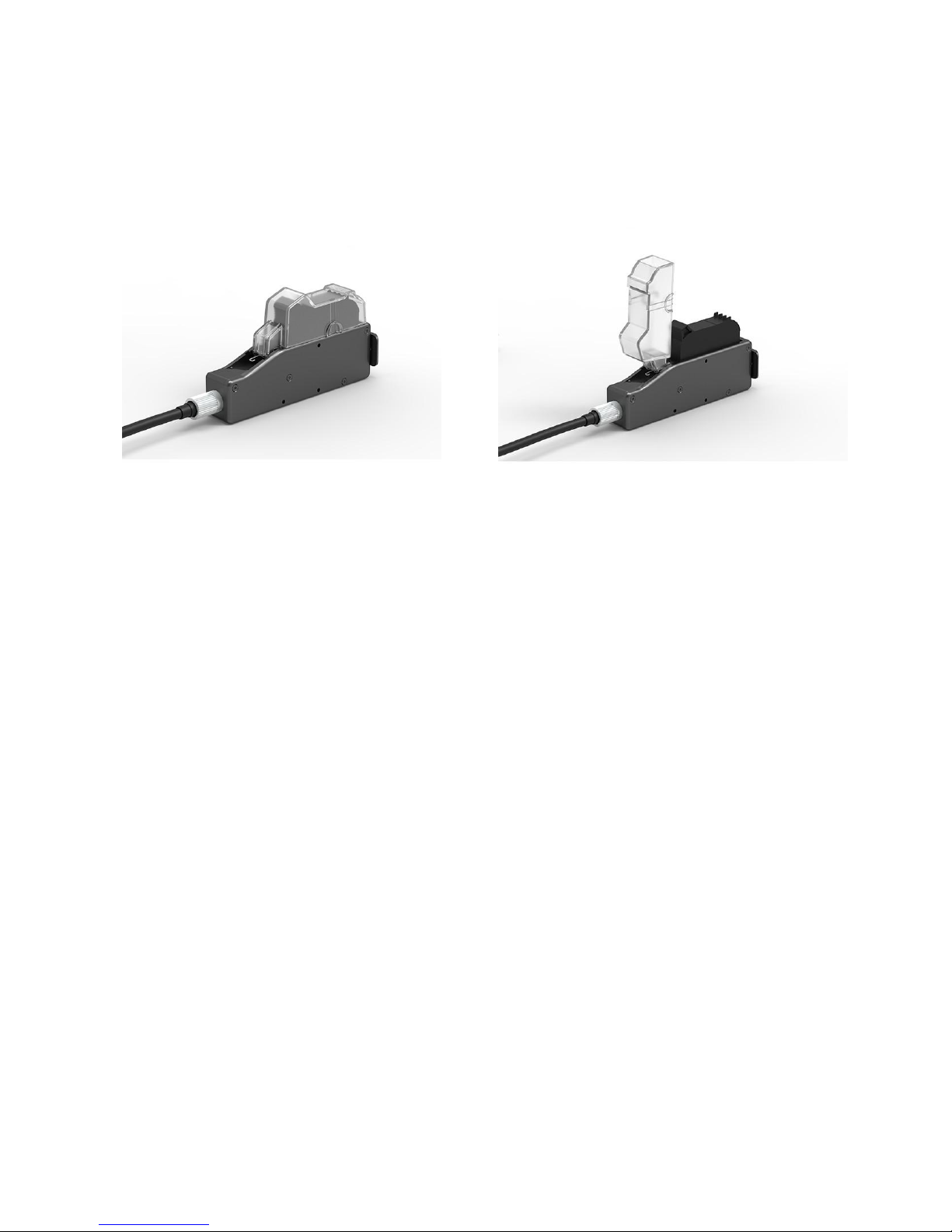
Chapter Two:Installation and Setup Instructions
This chapter is about how to install the machine and cartridge. Firstly please check the packing list
below
Packing Picture

8
2.1 Packing List for Spare Parts
Please check everything with packing list to make sure all required parts in the package when you
receive the products.
1、Controller 2、Printer head
3、USB
4、Power line
5、Power supply adapter
6、Printer head
connection line
7、Ground line 8、Round bar fixer X 2 9、Round bar
10、Bi-direction bracket 11、Bi-pass clamp x 2 12、A. M8*16 SCREW: 12PCS
B. M4*8 SCREW: 4PCS
13、Inner hexagon spanner

9
2.2 Device installation
2.2.1Side printing installation
2.2.2 Down printing installation
10
2.2.3 Springback mechanism installation (optional)
Springback mechanism installation Anti-shock plate installation

11
Chapter Three: Device Introduction
3.1 Controller Introduction
3.2 Printer head Introduction
Power switch
Touch screen
Indicator
light
Power port
Aerial socket
DB15 Port
Ethernet
port
USB1
USB2
Aerial socket
Dust cap
Anti-shock
plate
12
3.3 Technical Specifications
A. Performance Index
Items
Specifications
Note
Technical source
HP TIJ 2.5 Thermal Ink Jet technology
Dimension
Controller(H*W*D): 151*93*32mm
Printer head(H*W*D): 175*52*33mm
Bracket size
3pcs steel tubes with diameter at 16mm
1pcs with length 350mm, 2pcs with length 280mm
Clamp and bracket
not included
Power
30V/1A, 30W
With power adapter
Print height
1-12.7mm
Printing speed
and resolution
Horizontal resolution
(DPI)
Maximum speed (m/min)
600
30.4
400
45.7
300
60.9
150
121.9
Print application
Barcode, alphabetic, numeric, image logos,
date/time, expiration date, shift code, counter, lot-box
code
Connection Ports
1.Ethernet port;
2.USB2.0 port;
3.DB15 port.
4.DB25 port.
Interface
5inch full-color large LCD touch screen with
resolution 800*480.
Ink management
1.Automatically recognize ink types, and identify
optimum printing parameters for each ink type;
2. Guarantees genuine original HP ink using;
3. Automatic measure system for the usage condition
of ink.
Installation method
Side printing, down printing and anti-shock bracket.
Product Certification
CE, FCC.
Working
Environment
1. Working environment: -10°C~ +55°C; 10%-85%RH;
2. Storage environment: -25°C~ +80°C; 10%-90%RH.
B. Features:
Items
Specifications
Note
Language
Chinese, English, Japanese, French, German,
Spanish, Portuguese and Russian.
Font
Default font is Arial; allow users to load fonts they
need.
Barcode
UPCA, UPCE, EAN13, EAN8, INT25, CODE39,
CODE128, EAN128, PDF417, DATAMATRIX, QR.
Date format
Variety of date format available
Counter
Flexible setting for common counter, carton counters.
pallet number
Print speed
Print speed can be set up, automatically testing, or
speed testing by external encoder.
Built-in photocell
Suitable for simple print
C. Ink Solutions:
1. Support 42ml, 370ml, 350ml cartridges of HP TIJ2.5technology;
2. Support ink of various colors: black, red, green, yellow and blue;
3. Support porous, semi-porous and non-porous substrates.

13
Chapter Four: How to Use the Printer and check
before/after Use
In this Chapter, you will learn how to master and use printer quickly, including inspection work before
and after use.
4.1 How to Use the Printer
SN
Steps
Instructions
1
Cartridge
Installation
Insert cartridge into the printer by an angle of 15 degree, lock cartridge clip to
secure. (see 2.3 Cartridge Installation)
Connect power adapter
2
Power on
to printer power input,
switch on power, printer
enters initialization
3
Main Interface
---
Printing
Management
“main interface” enter after
initialization (see Section 5.1).
Click to enter
“Printing Management” (see
Section 5.2).
4
Select data Start printing
Select data, and click
to Start printing.
5
Printing
report
When printing start, the
button change to the icon
for printing stop,
meanwhile a printing report
appear.
6
Printing stop
Click to stop
printing, then return to “Start
printing” status
7
Switch off
Exit printing, and switch off power.
4.2 Check Work before Use
SN
Items
Check Work
1
Printer
bracket
Make sure the bracket mounted tightly?
2
Printer
position
Make sure the printer position correct? Is the nozzle plate parallel to printing
object? Is the throw distance controlled within 0.5-2.5mm?
3
cartridge
Is the cartridge wiped clean? is cartridge installed on printer?
4
Power input
Is the printer input voltage normal?
5
Printer status
Check status bar, does the machine run normally?
4.3 Check Work after Use
SN
Items
Check Work
1
Printer Power
Status
Is the printer power switched off?
2
Cartridge
Make sure the cartridge removed from printer, then clean and cap the print head?

14
Chapter Five: Printer Operation Instructions
This chapter is about how to operate printer interface, including Printing Management, Data
Management, System Management, Tool Management, and Status Bar.
5.1 Main Interface
Switch on power,
Setting
Manageme
nt
Printing
Manageme
nt
Data
Manageme
nt
Status bar
(Image 1)
printer starts
initialization
After
initialization
startup, “main
interface” appears
(see Image 1).
Printing
Management
ToFind/Preview, create-new, Edit, Copy, Delete data (see 5.2).
Dat
a
Management
Tomanage system setting, editing options, printing options, user authority,
and screen correction setting (see 5.3).
System
Management
Tomanage image logo, system upgrade, system backup, system record,
equipment default restoring, system resetting (see 5.4).
Tool
Management
Display information of ink, equipment, USB, encoder, external photocell,
Ethernet status and Clean Printhead (see 5.5).
Status bar
Display information of ink, equipment, USB, encoder, external photocell,
Ethernet status and Clean Printhead (see 5.7).

15
5.2 Printing Management
Click on main interface
to enter printing management
(see Image 2)
Preview
interface
Scroll bar
Start
printing
Printing
delay
Search
File name
Keywords enter bar
Page up
Page
Down
Return
(Image 2)
5.2.1 Find/Preview Data (see Image 2)
Preview data Preview data by locating or selecting a file or data to display on preview interface;
data located/selected will be displayed on preview interface, and you can view
them which beyond the page by dragging the slider.
5.2.2 Start Printing / Printing Report
Click
button to start
printing. When printing starts,
printing report appears (see Image 3).
Printing report: It is the timely record
of printing in process, including data
file name in process, print output
quantity, counter value, dynamic text
shift,,system time. The printing
report exits when printing stop
Stop
printing
Printing
report
(Image3)
5.2.3 Printing Delay
Click , printing delay
interface appears (see Image
4)
See Appendix 1: Terms
and Definitions 1 for more
information.
(Image 4)
A. Printing delay default value: 30mm;
B. Printing delay value range: 0.0-999.9mm;
C. Set printing delay value is allowed during printing operation: the newly setting value take effect
immediately from next printing.
D. Printing delay value for each message are independent from one another, the delay setting for current
data file will not affect another data file.

16
5.2.4 Print Initial Value
Click to enter
the
initial
value setting and repeated index
value interface
Hex switch: Click ,the current
counter value can be changed, but
the set value can’t be changed
DEC-10 decimal (0-9)
H36-36 hexadecimal (0-Z)
The Hex is editable; See 5.4.2
Hex switch
Counter
synchronized
Counter Synchronized: when multi
counter included in the same file,
click
, then all counters’
current value will be default value
1 synchronously .
Click “confirm”, Interface will
indicate the counter setting
interface, you can set counters
minimum, maximum, repeated
values, step values, and
hexadecimal rules.
String: all the same strings that
exist in the data are modified
synchronously after a string is
modified
CSV: If the document contains the
CSV file, you can modify initial
printing content at the start page
5.2.5 Stop Printing
Click
to stop printing and exit printing report, return to Start Printing status (see Image 2).
Note: Printer automatically stops printing when power off, cartridge empty, counter alarming etc.
5.3 Data Management
Clip on main interface to
enter data management interface
New
Modify
Delete
Copy
Delete all

17
5.3.1 New/Edit Data
Clip or on data
management interface to enter data edit
interface.
A. New data: text, counter, shifts,
production date, expiration date, image
logo, barcode, dynamic text, dynamic
logo, device information, string, CSV;
B. Edit: data in printing process cannot
be edited;
C. File name: maximum 15 characters,
empty file name or repeated file name
are not allowed.
Image Logo
Expiration date
Production
Page up
Text
Add objects
Delete object s
File name
Dynamic text
Counter
Barcode
Shift code
Click to save data when finish
edit, interface jump out to ask “Are you
sure you want to save the message?
Cancel, Yes, No”
If you click
the machine
will remain on editing interface.
Note: “MSG001” is default data in system. The system allows maximum 500 files or data (including default
“MSG001”); The system does not save empty or error messages.
5.3.2 Add Text Object
Click to add text object, see Image9.
Click
to enter text editing interface:
A. Font: including the default one, support
2 fonts, (the default one and another
alternative font).
B. 12-156mm height( adjust freely within
the scope of 1-12.7mm);
C. Text horizontal scale: 1-300%;
D. Text content , not exceed 78 words
Horizontal
scale
Height
Text
Edit
Vertical
scale down
and
location up
Vertical scale up and
location down
(Image 9)
Dynamic logo
String
Device
information

18
Note: Please refer to this Section ( 5.3.2) regarding how to add objects as “production date”,
“expiration date”, ”image”, ”counter”, ”shift code”, “dynamic text” "dynamical logo", but the content of
“production date”, “expiration date”, ”counter”, ”shift code”, “dynamic text” "dynamical logo" cannot be
revised or adjusted directly when you add, and the font, height, content and font effectof “image”
"dynamical logo" cannot be revised directly. There is no option for horizontal scale for “image”
“barcode”, "dynamical logo".
5.3.3 Add Production Date
Click
date”.
to add object “production
Click
to enter date format setting,
Select a set calendar format by Up and down
adjust.
Gregorian and Moslem calendar available
(Image 11).
Date format
Calendar Type
Settin
(Image 11)
5.3.4 Add Expiry Date
Click
to add expiry date
Click
to enter date format setting
It is available to set up Date format and valid
days (scope: 0~9999)
Gregorian and Moslem calendar available.
(Image 12).
Expired
Days
Calenda
r

19
5.3.5 Add Image
Click to add image
Selecta image on file list by page
up and down ( Image13).
Image
file list
(Image 13)
Note: When there is no image file found,
a window jump out to remind you image
importing (Image 14).
See 5.5.1 Image Management for
image logo import.
(Image 14)
5.3.6 Add Counter
Click to add counter.
Click
for options of common
counter, box number, lot number.
A. Click
for common countersetting:
minimum value, maximum value, stepping
value, repeat number ( Image 15).
Common
counter
Box No.
Lot No.
Stepping
value
Repeat
number
(Image 15)
B. Click
to enter box number and
pallet number interface, current value, mini
value, max value, step value for cartonand
pallet number (see Image 16).
Note:
1. Please set up carton number at
first ,then set up pallet number
2. No duplicate value setting options for
carton and pallet number.
Minimum
value
Maximum
value
(Image 16)
value

20
5.3.7 Add Shift
Click to add “shifts code”.
Click enter the setting interface:
can set shifts interval, start time and shifts
numbers.
A. Shifts Interval : 9 options:
Start time
0、0.5H、1H、2H、3H、4H、6H、8H
、
12H,each option makes a day to the
responding shifts number.
Such as: interval value 8H, means 3 shifts
per day.
B. Start time: set the time for the first shift.
Note: 24-hour time system.
C. Shifts: set shifts numbers.
While interval value is 0, shifts can be
inputted freely from 2-48.
D. Click to view the detailed
information.
E. Shift: set the shit name, time.
F. Shift name: maximum 5 characters.
G. Shift time: can set different time, shifts
will be changed according to time.
Interval
Shifts

21
5.3.8 Add Barcode
Click to add object“barcode”.
A. Click to enter barcode edit:
Barcode type, horizontal scale level, barcode
height, barcode text ( Image 18).
Code text
(Image 18)
B. Click to enter barcode
adjustment: coordinate location, text
orientation( Image 19, ).
Note: Setting options may differ depending on
different barcode types.
C. Click Special, set bar code text hidden/
display, font switch, font size, error
correction level, blank space level, twodimensional code specification.
: Textdisplay;
: Texthide;
~
: error correction
level;
~
: white space
level.
Barcode specification: size of 2D code
Text height: barcode text height
Font type: choose barcode font
(Image19)
Code height
Code
width
Code
type
Error correction level
Code
specification
White
space
level
Text
height
White
space
Text
display
Font
type

22
D. Click
Enter barcodes setting interface:
User can create, edit and delete data sources
inthe barcode content.The data sources including
10 objects: text,production date expiry date
counter, shifts, dynamic text, device info, CSV,
string and carriage return.
After create a new object,
its name will show up in the list, user can sort the
objects by up and down arrows.

23
5.3.9 Add dynamic text
Clip to add dynamic text.
A. Clip to enter the interface of
dynamic text setting, and you can choose
dynamic transmission path and
communication protocol
B. Scan printing
Port is USB, selection modes are:
S1P1: scan one while printing one
S1PN:scan one while printing multiples
until next scan data
SNPN:scan multiples while printing
multiples, repeated print times also
available
SGPN: Fix scan numbers and print
numbers,repeated print times and scan
numbers available
5.3.10 Add dynamic image
Click
to add dynamic image
(Image 23)
Note: please refer to step 5.3.9 to add
dynamic text, set the data transmission
path and communication protocol.
(
Image
23)

24
5.3.11 Add Device Information
Click , add device information;
Clip , enter device information
setting interface, choose device name and
device SN No available
Device name can be defined by entering 5.4.5
user management to define and device SN
can’t be changed.
5.3.12 Add String
Click to add string.
Click to enter the string setting
interface. The system default can add 5
different strings. single data allows maximum
20 string objects, each string with maximum
75 character.
Note: when add the same string, other same
strings will be modified automatically once one
of strings modified.
25
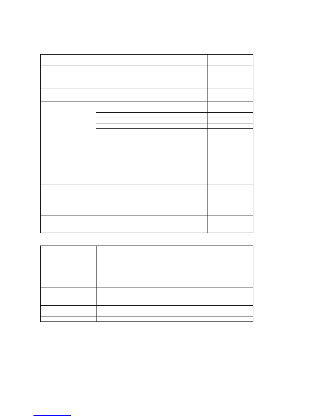
5.3.13 Add CSV File
Click CSV to add the CSV file
A. Put the CSV file under the U disk
(Inkjet/CSV/) path
B. Inserts the U disk into the device. The
device automatically identify the CSV file
and switch options
C. Select the file, Switch and choose the
required content
D. click on No print for the first line,
click again to switch to the first line to print
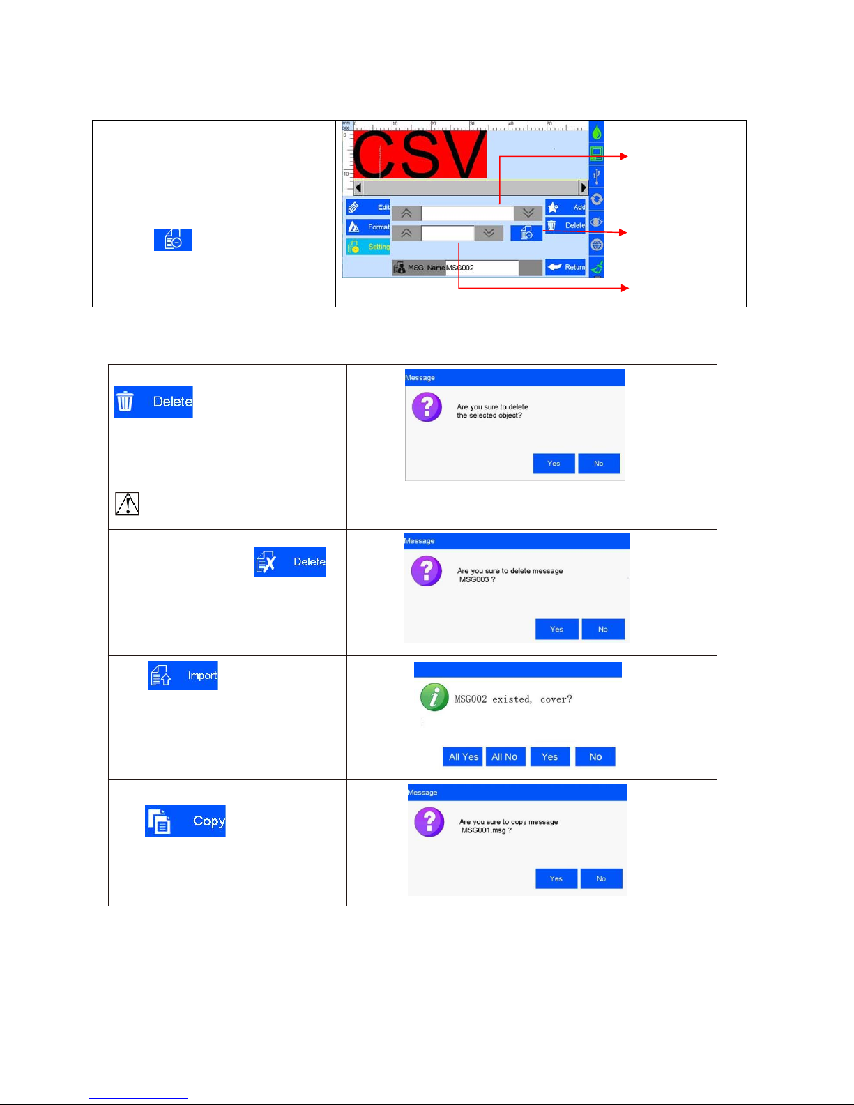
5.3.14 Delete Object or Delete/Import /Data copy
Select an object on data edit interface,click
to delete the object, and a
dialog box appears ,please refer (Image
24)
( Image 24)
Select the file on the file list of data
management interface , click
to delete the file, a dialog box appears,
please refer Image 25.
Note: All data in printing cannot be
Deleted
( Image 25)
Click in FileManagement
interface,it will import all files saved in U
disk under defined route. A dialog box
remind you to cover or not.
Select an object on data editing interface,
Click to copy data ,“C1”
be added on the original data name after
data copied. E.g. the files name of
MSG001 will changed to MSG001C1 .
Select CSV flies
First line not
print
Select filed

26
5.4 System Management
Click
to enter system
Management interface ( Image 26).
Special
Features
User
management
Printing options
Editing options
System setting
Screen
correction
(
Image
26)
5.4.1System Setting
Click on system management
interface to enter system setting
(Image 27).
System Language
System time
Screensaver time
Unit
Calendar Type
Daylight saving time
(Image 27)
A. System language
The language of Shipping country is standard language as default
B. System time
Manufacture time as default time, user also can set the time
C. Screensaver time
see Appendix 1: Terms and Definition 3.
1) System default 4hours, 4 cycle switching : 0.5H,2H,4H, off (8H)
2) If screensaver is optioned OFF, screen enters standby status
3) Screen becomes active when there’s alarm or error.
D. unit
Switch between mm and inch.
E. Daylight saving time Three setting modes: OFF, European summer time, US summer time.
F. Calendar Type
Two setting modes available: Persian, Gregorian & Moslem
calendar .Gregorian is default calendar; the System time will be updated
according to the calendar setting.

27
5.4.2 Edit Options
Click on system management interface to enter edit options setting interface.
A. Click to enter production date
Date format
and expiry date format setting.
New format
Note: Seven common date formats default,
Forty-three more formats addable for
user. The seven default date formats
Edit format
can not be deleted.
Delete format
Click I to modify date
format,
click
to delete the existing date format.
Note:
Year/Month/Hour/week have 2 hex
options: decimal/36 hex, before
operating first need to select hex and
Hex switch
1. Year, options are: ---4-Digit, ---Last 2 digit, ---Last 1 digit
2.
Month, options are: ---Full digit, ---Jan to Sep is1-9, Oct to Dec is O/N/D
---Abbreviations, ---Full English
3.
Hour,options are:
--24H system, ---12H system
B. Click to enter special time
Setting .
Date transition
time setting
see Appendix 1: Terms and
Definitions 4, 5.
Pre-zero in
date/time
Special time
setting
1) Date transition time setting: Off is system default, zero point is normal date transition, users can set
different time as date transition .
2) Pre-zero in date/time: four options: OFF, empty preposition, empty postposition, content centered
without blank. (e.g. 2012/05/09, 2012/_5/_2, 2012/5_/2_, 2012/5/2).
C. Click to enter counter
setting.
Capacity
counter
Counter
pre-zero
Counter alarm
Counter reset
Counter setting
1) Capacity counter: setting range: 0~99999999.
2) Pre-zero: Click the down button to switch the four options (e.g.:0001、1、1、1 ).
3) Counter alarm: ON or OFF option. When counter alarm is turned ON, the machine will stop printing
when print number reaches maximum value.
4) Counter reset: ON or OFF option. All counters will start from initial values if the counter reset is turned
ON. The printing value will continue from the last printing if the counter reset is turned OFF.

28
D: click ,enter the system
setting interface.
The system can be new-build,
modified, and deleted,
system default: DEC-10 decimal (0-9)
H36-36 hexadecimal(0-Z)
The default hex can't be modified or
deleted
New system
Modify system
Deletsystem
System setting
New-build and edit the system
1.
Input the system name with three
characters and Images only allowed.
2.
System content: Input Arabic number
from 0-9, 26 capital letters (A-Z) or
lowercase letters(a-z),non-repeated
input
System name
System content

29
5.4.3 Printing Options
Click
on system management interface to enter printing option setting.
A. Click to enter nozzle
maintenance setting.
Note: 1) Pre-purge Mode: 2 modes : both right & left nozzles; the working nozzles only.
2) Pre-purge:5 shifts: OFF, low, medium, high. see the following Images:
--Off;
--Low; --Medium; --High
--Custom Setting: User can set the interval from 1-3600 sec.
3) Object Width: After inputting the object width, the printer will not prepurge while the object passing to avoid
potential pollution.
4) One key clean: spit 300 ink dots one time; the function fail if the button is on during printing
B.
Click to enter print
head
setting.
C. Cache number: Printing numbers
in memory
D. Clear Buff: Clear the cache. This
function defaults to shutdown.
When set to open, The clear
cache button is displayed in the
printing report, and the cached
data is cleared by clicking the
button
E. Pre-Print: The pre-print
displayed when pre-purge is
open. Induction once ,Spray
once
Note: printing direction: system default from left to right.
1) Four directions optional: left-to-right,right-to-left, mirror sides of left-to-right and right-to-left, see image as follow:
--Left-to-right; --Right-to-left; -Mirror side of left-to-right; --Mirror side of
right-to-left.
2) Channel switch: Left channel is default, Left channel, Right channel, Dual channel, see the
image as follow: --Left channel; --Right channel; --Dual
channel.
3) Printing
Recovery: when the set is , The system automatically restores the printing
status before the power cut and automatically starts printing
,The default setting is .
Note: When the printing contains counter, operator need to check on
the counter value and do needful adjustment before the Printing Recovery is "ON",
see Appendix 1: Terms and Definitions 8.
Pre-purge
Pre-purge
Mode
Object Width
One key Clean

30
D. Click to enter production line
Setting.
Line speed
Line speed: system default 30m/min;
Adjustable scope 1~150m/min
;
DPI: system default 300DPI; adjustable
DPI
Scope 50~600DPI.
Line speed
setting
Run speed
test

31
Click on line speed setting
interface to run speed test
( Image 35, 36).
Line speed test: input test object length
0~3000mm, click
to enter speedtest
startup interface, then start production line,
put test object onto production line, the
photocell will be sensing the object, and the
machine will calculate line speed
automatically. Click to save current
speed test result. Click , current
speed test value will not be saved. If test
repeated, system will take average value of
multiple results. Click to stop speed
test, and click or to save or
give up test result.
Speed
Test object
length
Run speed test
Cancel
Save
(Image 35)
Stop speed
test
(Image 36)
Note: if external encoder is connected, system would detect encoder automatically, and
change line speed interface to encoder DPI setting interface. User will not be able to set
the line speed
5.4.4 User Management
Click on system management interface to enter user management
A. Device name: user-defined available, the
maximum is 15 characters.
B. User permission management switch:
system
default OFF. A dialogue box requests user
name and password for access to log in.
C. User name : Create user name according
to different permissions, managers as the
highest authority, can set up and modify the
password; engineers can edit the data and turn
off printing; the operator only open and close
the print data available.
D. Password and confirmation:
administrator creates user name and
password. Maximum 15 characters for
password.
888888 is default password for administrator
(Image 37)
Note: Please contact local dealer or Sojet for printer unlocking when youforget
administratorpassword.

32
5.4.5 Special Features
Click on system management interface to enter “Special
“Features
“ setting.
A. Click to enter “Special printing”
Setting .
Special
printing
Continuous printing:
Continuou
s
output
Output
See Appendix 1: Terms and
interval
Definitions 9 for more information.
1) Continuous output times: system default
0 (OFF). Adjustable scope 0~9999.
Note: 0 means OFF; 9999 means infinite
Continuous printing
2) Continuous Output interval: “off’ is default
adjustable scope 0~999mm.
Round printing:
Two-way printing, from left to right(forward
print) or from right to left (reverse print)
1)Reverse frequency : printing direction can
be reversed automatically when the system
Reach the set printing times. For example,
the set printing times is 3, when printing
finished from right to left, the printing
Reverse frequency
will be changed automatically from left to right
Reverse delay
system default : 0 (off)
Round printing
adjustable range: 0 -9999
2)Reverse delay : printing delay according
to the set direction
system default : 0 (off)
adjustable range: 0 -999.9
it should be set before printing not during
printing process
Note: normal delay (from right to left) set in
the printing interface. see: 5.2.3
B. Click
to enable “Value-added
function ( Image 39).
Value-added
function
Note: Enable special features by
registration code like (1/2 ink saving,1/4 ink
saving, Probation period)
Registration code
(Image 39)

33
C.
Click and enter Alarm
settings. Three options as below: Red
Light, Buzzer or Line Control ( Image
40 ).
Red Light: When the device is in
the following selected state, the
tricolor light for warning
Buzzer: The tricolor light will issue
a buzzer alarm.
Line Control: The tricolor light will
turn to yellow for warning and stop
operation.
When the above situation happen,
printer will transfer the error signal to the
production line via DB15 ports, user can
set up the production operation like stop
or etc.
5.4.6 Screen Calibration
Click
on system
Management interface to enter screen
Calibration ( Image 41).
Note: Please calibrate screen when
inaccurate screen position occur, click
Icon “+” as screen hint ,it will exits
automatically after screen calibration
finished, a verification message indicates
success or failure operation.
(Image 41)

34
5.5 Tool Management
Click on main interface to enter
Tool management interface
About printer
System logs
Backup
management
Upgrade
management
Image Logo
System reset
(
Image
42)
5.5.1 Image Management
Click to enter image Logo
management interface
( Image 43).
Image import: importing image from
USB or Ethernet.
Image format: Monochrome BMP;
Image height: 0-150 pixel point.
Image length
:
0-1000000 pixel point.
File list of
Image Logo
Import image
(Image 43)
Note: 1) System indicates and cuts the excess part if the imported image exceeds borders.
2) Image import cannot be executed when images exceed 100 pcs.
3) Image Logo restore route at U Disk: \InkJet\Logo.
5.5.2 System Upgrade
Click to enter upgrade
management interface
( Image 44).
User can use USB to upgrade the
software and add or change
languages and fonts.
(Image 44)
A. Software
upgrade
System automatically searches for software upgrade documents in designated folder and displays
the upgrade documents by list. User can select and upgrade any file in the list.
Document route under U disk : :\InkJet\Upgrade\Appliction
B. Language
upgrade
The machine is with multi- languages upon delivery. Special extra language can
be added if reques t.
Document route under U disk:\InkJet\Upgrade\Language
C.Resource
upgrade
Custom resource packs, Select the resource pack in the list and perform the
upgrade.
Document route under U disk: \InkJet\Upgrade\Res
D. Font
upgrade
System supports two fonts; user can add another font besides the default
Document route under U disk: \InkJet\Upgrade\Font
Note: Software upgrade documents, language documents, font documents can only be identified by
using the conversion tools provided by our company. The default language, font can’t be replaced and
deleted.
Delete image
Delete all

35
5.5.3 System Backup
5.5.4 System Logs
Click to enter system logs interface.
All operation content including operator,
operation and operating time
System logs include:
1)Printing function: Set up Log from initial value
2) New data management, modify, delete logs, import data
3) All logs in system management (including
screen calibration logs).
4) Image importing and delete logs, system upgrade, system
backup logs, and system reset logs.
Note: Enquiries, reading, and other logs are not included.
5.5.5 About Equipment
Click to enter equipment information
View interface
Information displays current hardware
version, software version, machine serial
number, dealer code, company Logo,
company name and website.
Clip to enter backup management.
Clip to enter backup operation
interface;
Export backup: including backup
documents, Image and Parameter
setting
C
lip to enter the backup restore
interface; can restore the message,
image and Parameter which in U disk to
the device;
Data optional:
1、 New: copy the data of U disk to the
device
2 、 Replace: replace the same name
data
3、Delete: delete existing data of device
4、Cancel: Not choose data
Options for image: new, replace, delete
and cancel
Optionsfor parameter: replace and
cancel
Note: Please check U disk connection status and disk space is normal when execute backup import and
export.
Backup document route under U Disk :/InkJet/Backup

36
5.5.6 System Reset
Click fromtools
management interface to enter the
system reset operation management
interface ( Image 48).
Click to execute system
reset. You need administrator
password for permission to reset
(Image 49).
(Image 48)
(Image 49)
Note: System reset is to restore all defaults.
1) Restore all to defaults, all data andimages are deleted.
2) All software version maintain current version; restore all languages and font to default.
After system be reset, relative parameters are as follows:
Item #
Items
Parameters
1
Language
English
2
System time
Manufacture time
3
Screen saver time
4 hours
4
Unit
Metric/mm
5
Daylight saving time
OFF
6
Date change
OFF
7
Pre-zero in date/time
OFF
8
Pre-zero in counter
OFF
9
Counter alarm
OFF
10
Counter reset
OFF
11
Pre-purge
OFF
12
One key cleaning
Standby
13
Printing direction
Left-to-right
14
Channel switch
Left channel
15
Print Recovery
OFF
16
Buffers number
5
17
Line speed
30m/min
18
DPI
300DPI
19
User permission management
OFF
20
Repeated output times
0 OFF
21
Data management
Only system default data Msg001
22
Printing delay
30mm
23
Printing initial value
Counter initial value and data source current value.

37
5.6 Input Methods Introduction
When click the input value in the input bar, the system interface automatically pops up the
keyboard input method. You can enter uppercase English, lowercase English, Chinese, numbers,
and common symbols (see Image 50, 51, 52, 53).
A. Uppercase: the system default
uppercase English input when
keyboard pops up
( Image 50).
(
Image
50)
B. Lowercase: click to
change between uppercase and
lowercase (Image 51).
(Image 51)
C. Numeric and common symbols:
Click to change
between numeric or common symbols
input ( Image 52).
(Image 52)
D. More symbols: click on
numeric/common symbols keypad for
more symbols (Image 53).
(Image 53)
Input method change
Numeric/common symbols and alphabetic input change
Reset (clear all input)
Delete (delete one character)
Hide keyboard
NOTE:
English for Arial fonts, characters in uppercase letters and numbers as the benchmark, lowercase letters
and symbols are not at same height

38
5.7 Status Bar
Ink
information
Ink information including dynamic and static information.
Static information including cartridge serial number, client
code, cartridge type.
Dynamic information:
1) Ink original volume , output volume for current printing data.
2) Ink used in percent, the remaining ink available for current data.
Ink status icons include:
1) Normal ( ): Normal ink status.
2) warning ( ): ink volume lower than 10%;
3) Error ( ): use wrong cartridge, cartridge uninstall, or ink use out.
Equipment
status
Hardware and software status of printer.
USB
information
Automatically displays the corresponding icons based on the type and status
of the device that the USB is connected .
Support three connection: USB , mouse, and keyboard.
Status: disconnection (gray), normal connection (green), warning (yellow)
These icons USB mouse keyboard will display once
device connected successfully
Encoder
information
Displays encoder
or photocell
connection status
like
disconnection
(gray) and
normally
connection(green
).
When encoder is
connected, click
to enter encoder
signal testing
interface
,
Photocell
information
When photocell is
connected, click
to enter photocell
signal testing
interface
,
Ethernet
information
The printer connection to computer is realized by
Ethernet port, therefore realizes device operation
and upgrade transmission on PC end.
Information including IP, mask code, gateway,
MAC; IP, mask code and gateway can be gained
automatically or manual input
Status including: disconnection (gray color);
Normally connection (green color, interaction with PC software normal);
Warning (yellow color, abnormal interaction with PC software ,
connection failure, the PC software not open, computer not turn on etc.)
One key
cleaning
Status including:
Failure status(gray)and one key cleaning
invalid while printing going on
Valid status (green) one key cleaning
available

39
Chapter Six: Maintenance
Inkjet printer is a kind of precision machine, if the daily maintenance is not timely and in place, it easily cause different
kinds of faults and bring a lot of inconvenience! In order to prolong the service life and improve the utilization rate, it is
necessary to arrange special personnel for the management and maintenance.
6.1 Printer Maintenance
6.1.1 Make sure power cable, power adapter cable, grounding cable is in good condition. Make sure the connection of
each cable is reliable.
6.1.2 Make sure the screw for grounding wire is secured and the grounding is reliable.
6.1.3Make sure the equipment is not displaced before turn on. Make sure the nozzle is parallel to printing object, and
printing distance is controlled within 0.5-2.5mm. (Please use the designed tools provided by sojet to secure the
mounting support).
6.1.4 Clean ink cartridge: wipe nozzle with Non-woven cloth to keep nozzles clean and unclogged. (Please refer to ink
cartridge care and maintenance for instructions).
6.1.5 Keep touch screen clean. Do not hit touch screen sharply.
6.1.6 Keep machine surface and ports clean.
6.1.7 Check status bar, make sure machine icon is normal and no alarm on status bar. (In case of alarm status, check
troubleshooting for solutions)
6.1.8When machine is turned off, make sure to remove the cartridge from printer, clean the nozzle and capthe print
head, place the cartridge in safe environment. (Please refer to cartridge care and maintenance for instructions).
6.2 Ink Cartridge Maintenance
Maintain correct methods for use and storage of the cartridge will keep the cartridge work with best print quality and extend
cartridge life. Please always follow instructions for Ink Cartridge Maintenance. The warranty will not cover damage or
failure caused by negligence not following our maintenance instruction..
6.2.1 Ink will volatilize slowly if the cartridge is decapped. Keep new and unopen cartridge in its original package.
6.2.2 Try to use up ink as soon as possible once the cartridge is open to prevent blocked because nozzle become dry in
short time. Note: Due to feature different, different inks have different dry time and maintenance ways. Contact our
after-sale service for more information.
6.2.3 If ink in cartridge is not used out at a time after open, remove the cartridge from printer and lock the print head with
customized cap and store in proper environment. Note: Do not use adhesive tape to seal the printhead, and do not
store cartridge in soft plastic bag.
6.2.4 Nozzle plate is delicate. Do not touch or clean nozzle with anything sharp or rough as not to scratch nozzle.
6.2.5 Use the Non-woven cloth provided by Sojet to wipe and clean nozzle.
Note: Wipe nozzle with the printhead facing down. Move the printhead in the direction of nozzle channel. Move the
printhead in the direction across nozzle channel will damage the nozzles.
6.2.6 Do not shake ink cartridge or expose in shocking environment. Shake or vibration will get air run into cartridge and
affect print quality.
To ensure best print quality, contact Sojet after-sale service for more instructions of different inks usage.

40
Chapter Seven: Common Troubles and Solutions
Note 1: The table below listing the most commonly seen problems and the solutions, If there’s any other problems, contact
your local dealer or our after-sale service for assistance.
Note 2: The table below is for reference only because each problem may differ depending on individual situation such as
installation environment and operation.
7.1 Troubleshooting and Solutions for Cartridge
SN Problems Analysis Solutions
Comments
1
The print has
broken line or
white line.
1. Nozzle blockage
or damage.
A. See Section 6.2 Ink
cartridge maintenance,
wipe and clean nozzle
with Non-woven cloth;
B. See Section 5.4.3,
Clean the nozzle using
one key cleaning
function
If the problem is still
unsolved:
Please check that the
drive panel contacts are
sunken and not bounce;
Check if dirty on cartridge
contacts
2. Cartridge not in
good connection
with printer.
Remove the cartridge and
re-insert.
2
The first half
print is
complete and
late half print
incomplete
Ink out or air
bubbles blocking
nozzles.
A. Check status bar if
there’s alarm of low ink.
B. Return to Sojet
for testing.
3
The print is
totally blank.
Ink used up
or nozzle total
blockage.
See Section 5.7 to check
ink status: is ink used up?
4
Unable to
identify ink
cartridge.
1. Connectivity
problem on printer
(defect or damage)
Remove cartridge and
re-insert.
If the problem is still
unsolved:
1,Please check that the
drive panel contacts are
sunken and not bounce;
2,Check if dirty on cartridge
contacts
3, Check if there’s
contamination on ISM card.
4, Check if there’s any
sunken connector on ISM
2. Cartridge dealer
code mistake.
Change new cartridge
and re-insert.

41
7.2 Troubleshooting and Solutions for Printer
SN Problems Analysis Solutions Comment
1
Printer
cannot be
turned on
1.No power input;
A. Make sure AC power
input on adapter is
correct, DC output on
adapter is well connected
with printer.
B. Check if power adapter
light is normal. Replace a
new adapter if light is
dead, dim or blinking.
2. Printer switch not
turned on.
Make sure the printer
power switch is turned
ON.
3. Device
damaged.
Contact local dealer or
after-sale service.
2
Printer
does not
print
1. Printing not started.
Click “Start printing”
button to start printing.
2. No printing data.
Select a file and click
“Start printing” button.
3. Printing delay value
too long
Check if the printing delay
value is normal.
4. Cartridge not
installed.
Install a cartridge.
5. Cartridge installed
but used up or
damaged.
Check cartridge status
according to Section 5.7,
is ink used up or cartridge
dealer code wrong?
If ink used up, or cartridge
dealer code wrong, replace a
new cartridge.
6. Photocell not works.
Testing Photocell refer
Section 5.2.2 to see if
output counter is working
in printing report
interface.
When connect with external
photocell, click for
photocell signal test interface
7. Encoder is
connected but
damaged.
Check if the encoder and
its connection wire are in
good condition; check if
the production line is
running well.
When the external equipment
is encoder, click for
encoder signal test interface,
move encoder to check if the
encoder works.

Appendix 1: Terms and Definitions
SN
Terms
Definition
Comment
1
Printing delay
It is the distance from the point when
photocell senses the printing object
to the point when printing starts.
User can adjust the right print
position on printing object.
E.g. Printing delay value is 30mm,
printer starts printing at 30mm point after
the photocell senses the printing object.
2
Printing
initial value
Counter Initial value during
printing
E.g. Set the initial value as 9, the counter
counting starts from 9 for first print.
3
Screen
saver time
It is a power saving function, the
screen will automatically turn off and
enter standby mode when the screen
is inactive for a while as set.
E.g. Set the screen saver time as one
minute. The screen will automatically
turn off and enter standby mode if the
screen becomes inactive for one minute.
4
the date
transition
time
customer can set a date for change
For example: Date change setting is
“08:00” ,Current date is 10/07 change
the time to 07:59,then the time of last
printing out before that is recorded as
09/07 07:59, after that is 10/07,8:00. If
the date transition time is 12:01,then the
time of last printing out before that is
recorded as 10/07 12:00,after that is
11/07.
5
Pre-purge
Nozzles become dry and cause
first half charactera unclear. user
can turn this function ON to
prevent the situation,
When Pre-purge function is turned ON,
printer will spray a little ink during idle
printing status to keep nozzle wet and
prevent dry.
6
One key
cleaning
Customer can use this function to
purge nozzles.
Purge whole nozzle to make sure
nozzles unblocked.
7
Channel
switch
Customer can switch different
channels to achieve best print
quality according to print need and
nozzle condition.
E.g. Option for single-channel printing,
when damage in left channel nozzle or
missing dots in print by left channel,
user can switch to right channel
printing.
Option for dual-channel printing to
achieve darker print and best print
quality.
8
Continuous
printing
Continuous same data printing
during the period that photocell
sensing the print object.
9
Printing
Recovery
When there is a power failure, and
the setting is "ON", system will go
back to the last printing status and
resume printing when power gets
back. The default setting for this
function is "OFF"
When the printing contains counter,
and the Printing Recovery setting is
"ON", operator need to check on the
counter value and do needful
adjustment.
42
 Loading...