

Page 1
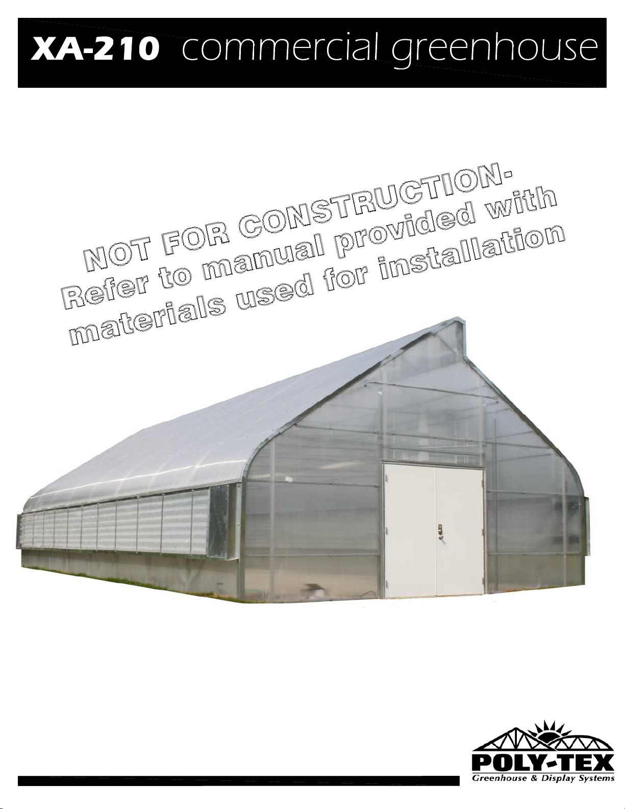
INSTALLATION INSTRUCTIONS
P.O. Box 458
27725 Danville Avenue
Castle Rock, MN 55010
www.poly-tex.com
REV: AC-121203
U.S. & Canada Toll Free
800-852-3443
(651) 463-7009
fax (651) 463-2479
Page 2
SAFETY GUIDELINES
PLEASE READ THE INSTALLATION INSTRUCTIONS CAREFULLY BEFORE BEGINNING TO
ASSEMBLE THE STRUCTURE. SAVE THESE INSTRUCTIONS FOR FUTURE REFERENCE.
WARNING
This structure is intended to be self-supporting once constructed with all frames,
hardware, sheathing, sheeting, bracing, cables, and membrane in place and secured to the
foundation as shown in the manual. Stability during construction, from winds and loads
imposed during erection, is the sole responsibility of the installer. Observe safety codes
required by your jurisdiction, and relevant safety practices for working at heights. Avoid the
risk of electrical shock from overhead lines or electrical storms. Poly-Tex recommends
contracting a licensed electrician to perform electrical work. Eye protection is recommended
under all circumstances and hearing protection is recommended when cutting components
with power tools.
Foundations
These instructions include minimum guidance for foundations based on the International
Building Code. These minimums are suitable for some areas of the country but not all.
Obtain a building permit if required in your jurisdiction. Engineered Certified foundation plans
may be required by a building official before issuing a permit. Even if not required, seeking
guidance from a qualified structural or civil engineer for the foundation design may improve
the life of the structure.
DANGER
No part of this structure is engineered to function as an anchorage point for a fall arrest
system. Use a safety net or work from a safe work platform (i.e. scaffolding). Select a calm
day for work. Wind can be sufficient enough to knock materials or workers off a work platform
or ladder, resulting in a potentially deadly fall.
Overview of assembly procedure
While each structure and site is unique, and may require special considerations, these
instructions are for a tilt-up method (where frames are assembled on the ground and tilted
onto ground stakes or anchor rods using ropes or lifts). If installer is not confident to erect the
structure, Poly-Tex suggests you hire a general contractor, carpenter, or similar licensed
business familiar with construction to assemble and erect the structure.
DANGER
Do not overload structure. Consult with a Poly-Tex representative prior to adding any
amount of weight over the specified capacity of this structure. Basket purlins, shelving or any
objects of significant weight shall not be hung, attached, or secured to roof or truss members
in a manner that will overload the structure.
WARNING
Do not walk on polycarbonate sheets. If the structure is to be covered with polycarbonate
sheets,always use scaffolding for the erection process to avoid damage to sheeting and to
ensure safety. Polycarbonate sheeting has UV coating protected with vinyl film on the
exterior surface. Install sheets with the film intact and toward the exterior. Remove film once
the sheet has been fastened in place.
AB-130117
Page 3
XA-210
Index
Fitting Identification
Hardware Identification
Site Layout
Ground Stake Installation and Greenhouse Leveling
Fitting Location and Truss Assembly
Ridge Purlin and Diagonal Strut Assembly
Attach Rain Gutters
Door Frame Assembly
End Frame Assembly
Truss Stabilizer Assembly
Cable Installation
Roll Form Layout (roof)
Installing Ridge Vent
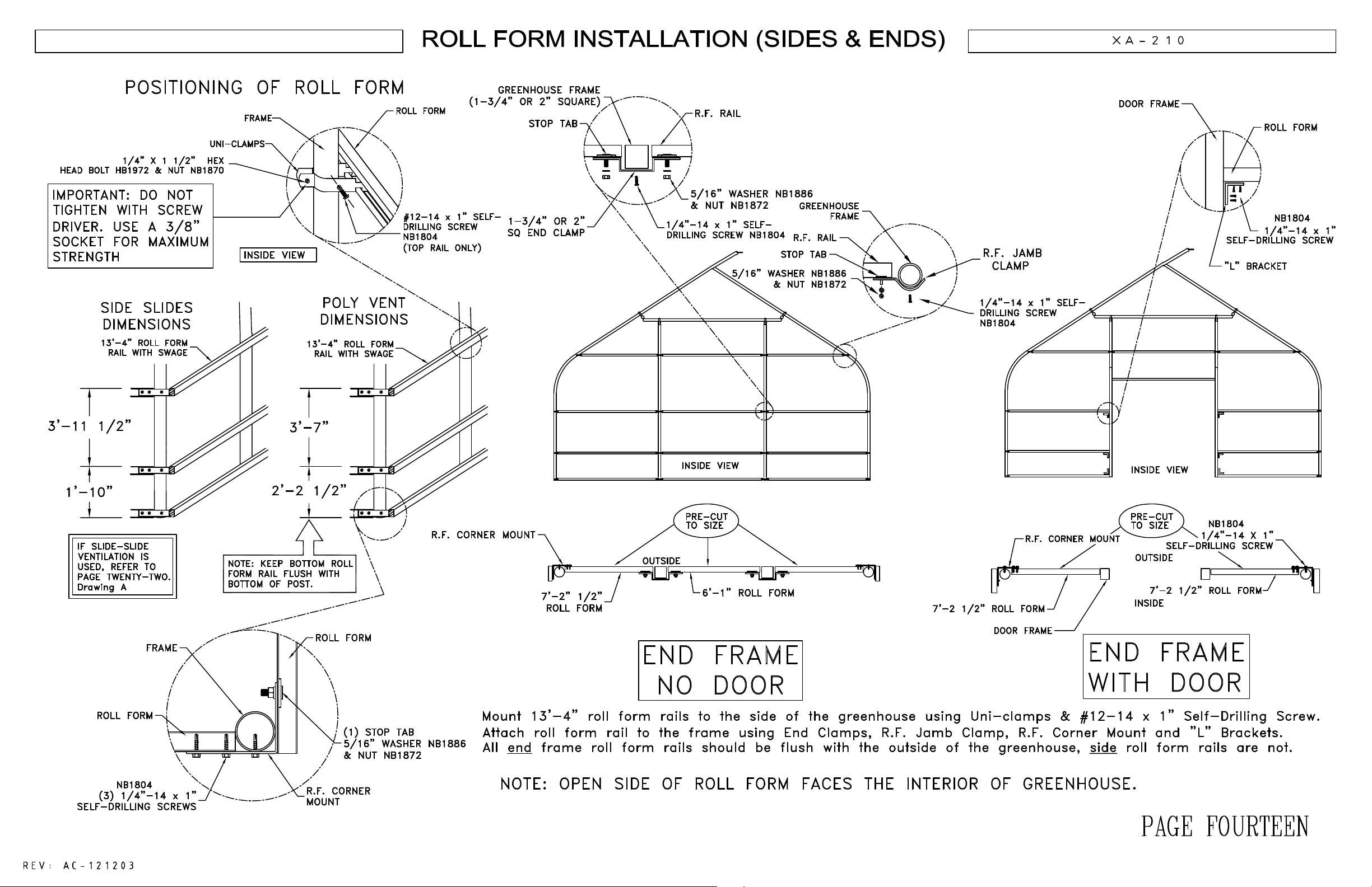
Roll Form Installation (sides & ends)
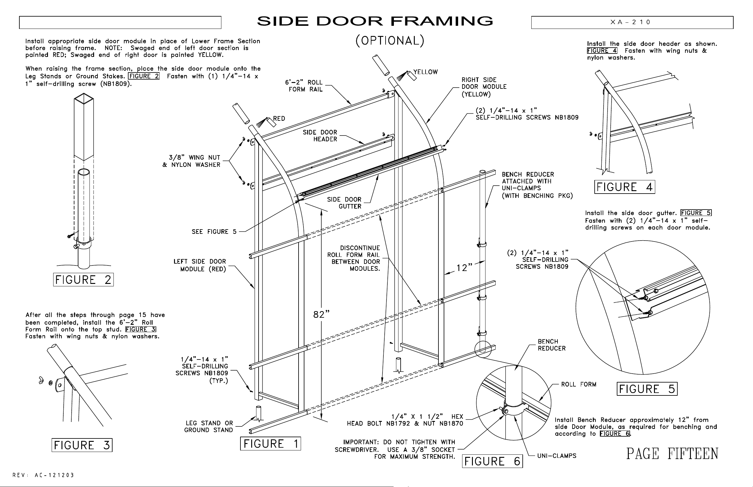
Side Door Framing
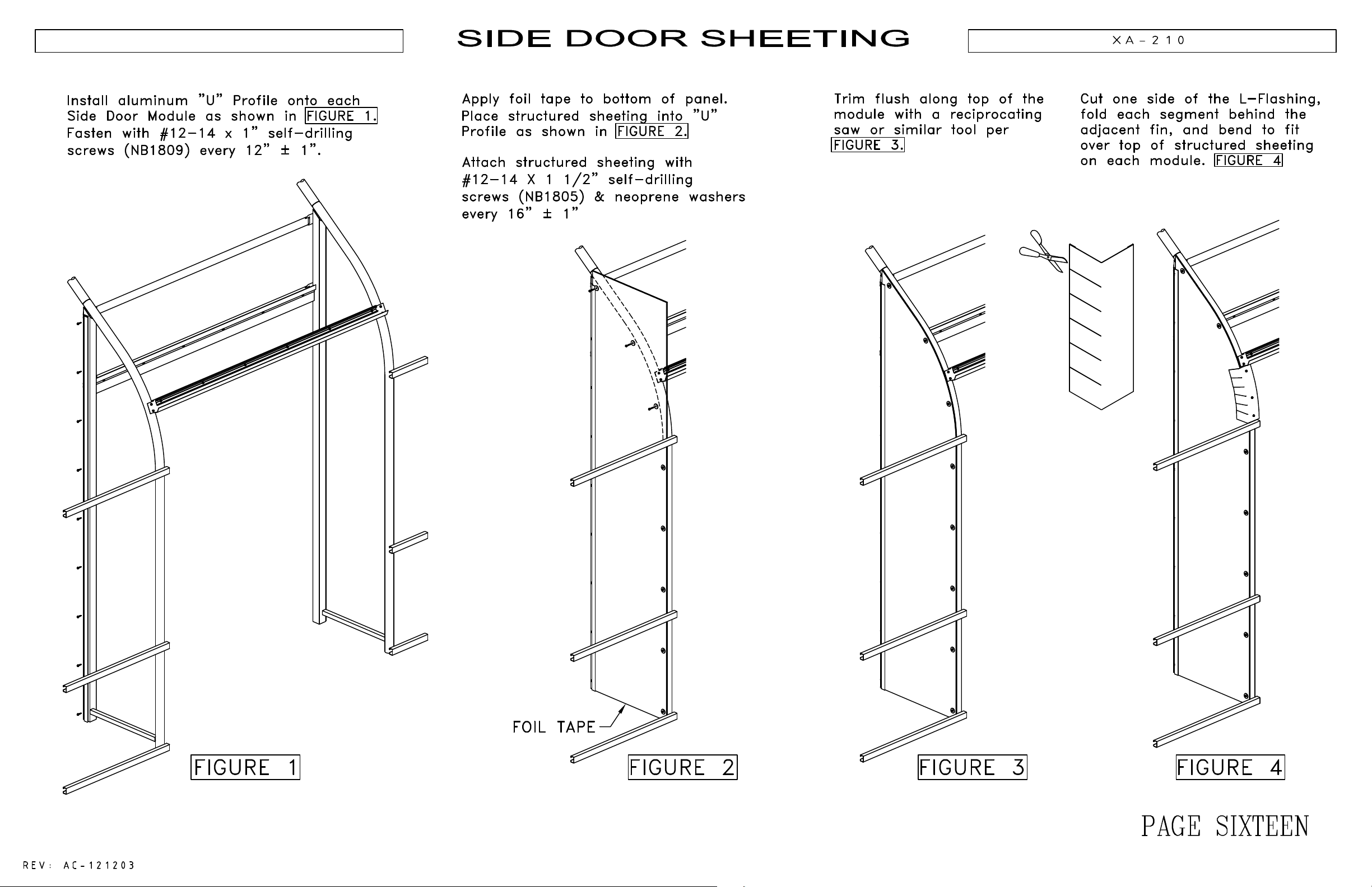
Side Door Sheeting
Page Number
1
2
3
4
5
6
7
8
9
10
11
12
13
14
15
16
Side Door Installation
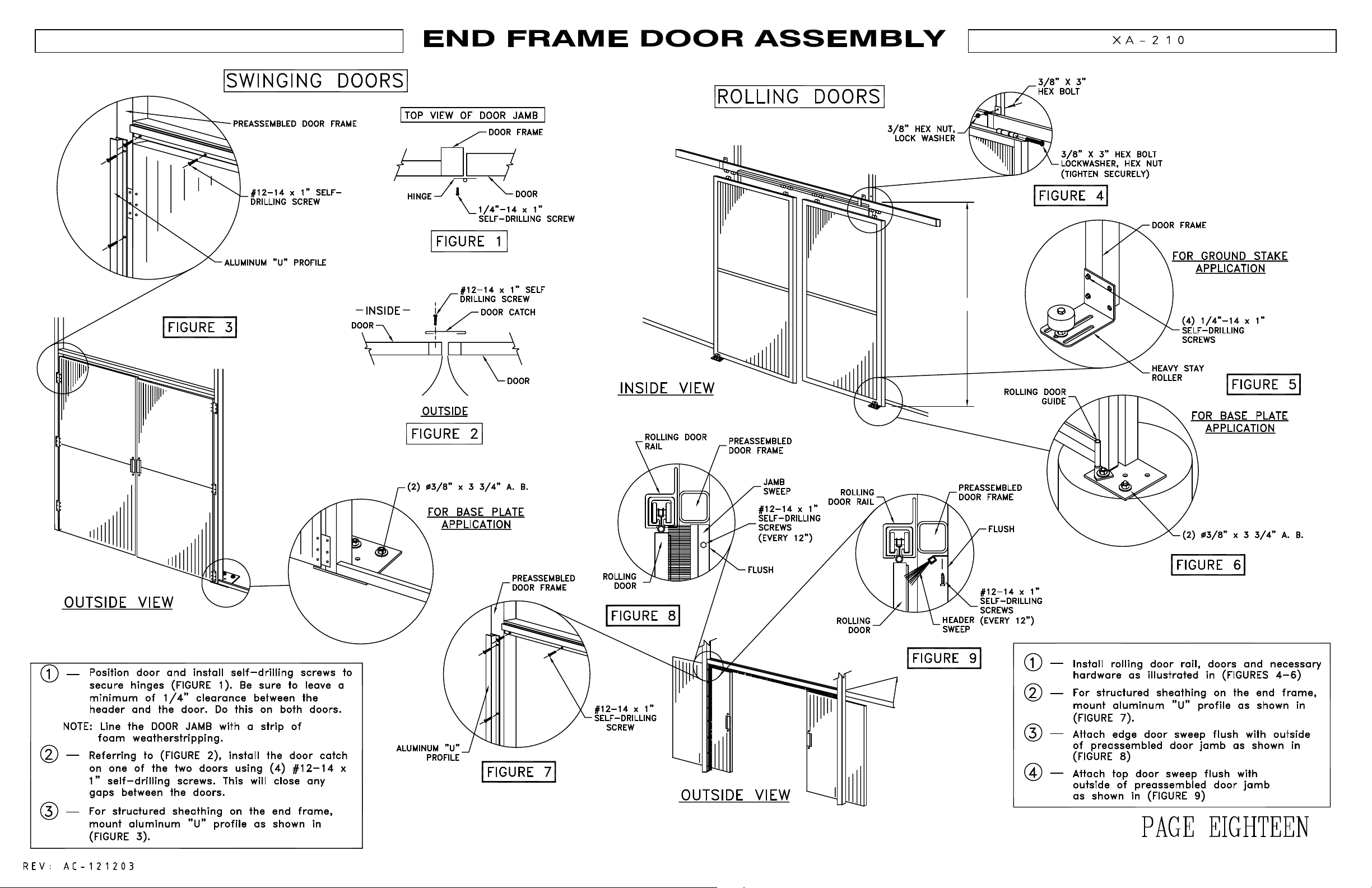
End Frame Door Assembly
Not used
Poly-Vent Installation (not used)
Tape & Aluminum Profile Location
Slide-Slide Installation
Structured Sheet Screw Pattern
Structured Sheet Installation for End Frame
Structured Sheet Eave Installation
Install Structured Sheet Roof
Slide-Side Panel Installation
Poly Fastener Location
Roof and End Poly Sizes
Inflating Roof & End Poly
Fan & Shutter Installation
17
18
19
20
21
22
23
24
25
26
27
28
29
30
31
REV:AC 121203
Page 4
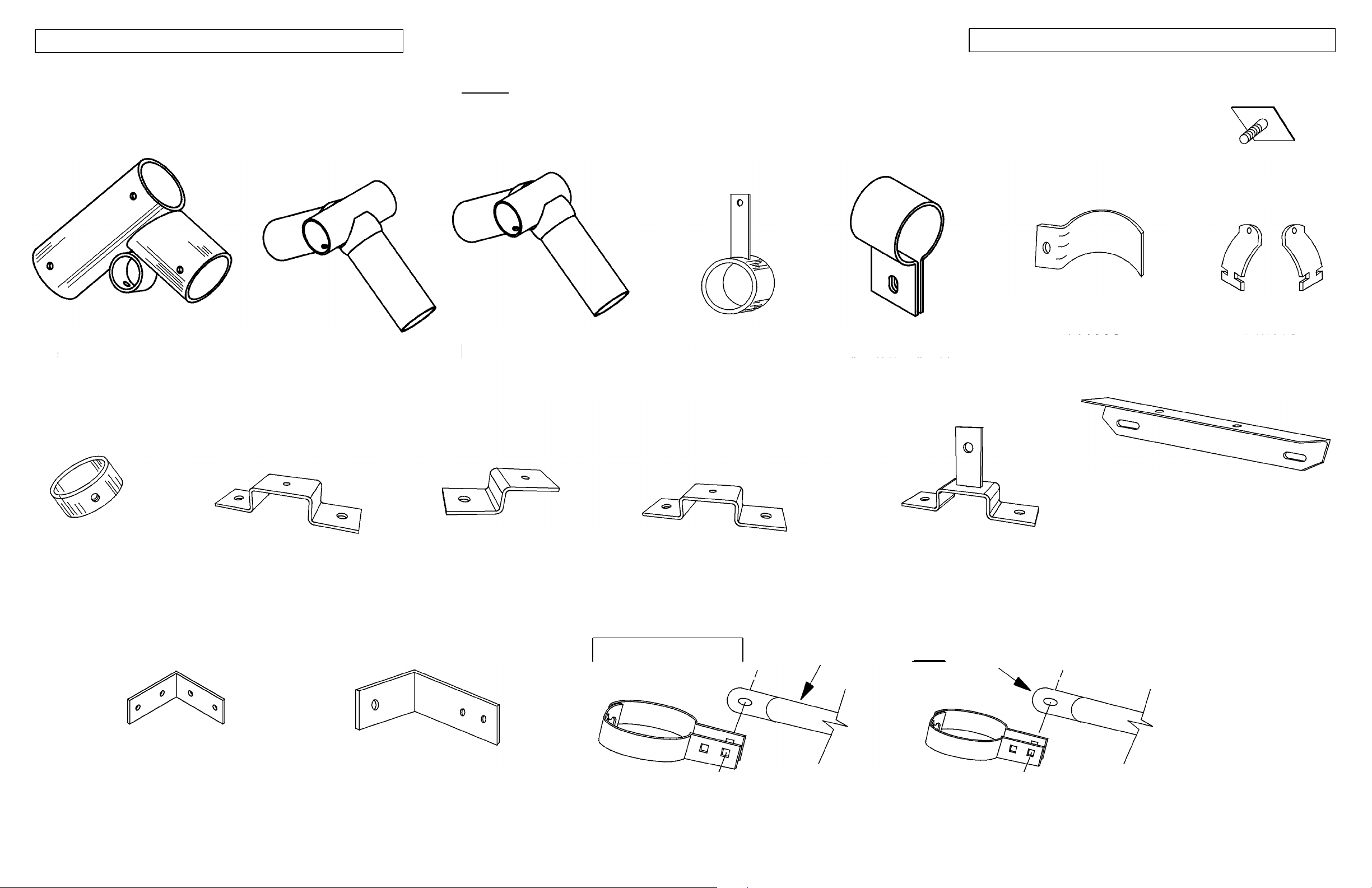
FITTING IDENTIFICATION
X A - 2 1 0
"K" FITTING
FT2032
PEAK FITTING
(RM-XA)
FT2093
NOTE:
ALL DRILLED AND TAPPED HOLES IN THESE
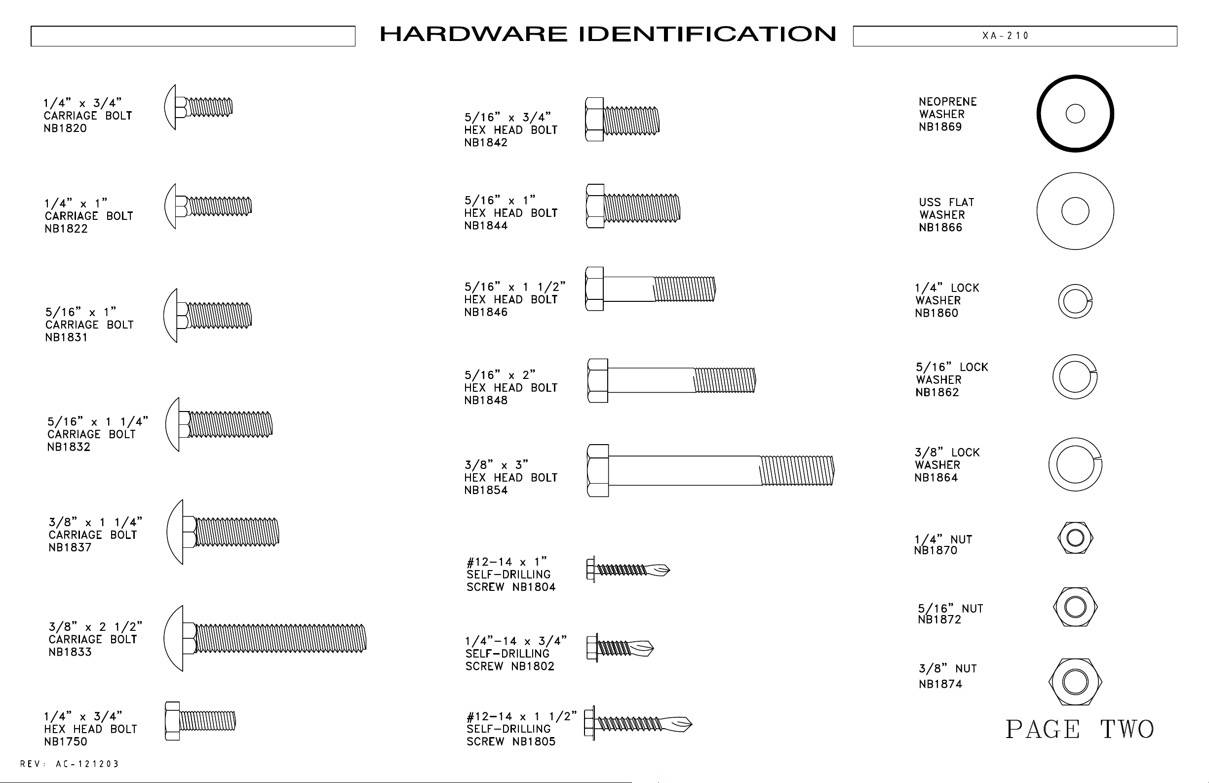
FITTINGS REQUIRE A 5/1 6" x 3/4" HEX HEAD BOLT.
(Some items may not be required for this structure)
END PEAK FITTING
TRUSS SOCKET C-BRACKET
(RM-XA)
FT2094
FT2043
HY2027
R.F. JAMB CLAMP
FT1998
STOP TAB
FT2570
UNI-CLAMP
FT2108
"A" FITTING
FT2001
"L" BRACKET
FT1990
2" SQ END CLAMP
FT1993
R.F. CORNER MOUNT
1 -3/4" SQ
JAMB CLAMP
FT2000
FT1995
1 -3/4" SQ END CLAMP
FT1991
IMPORTANT NOTE:
ALL COMPONENTS ATTACHED TO LONG SPEED HOOKS MUST BE MOUNTED ON
THE OUTSIDE OF THE TABS.
(2) LONG SPEED HOOKS
(FOR 2" DIA)
FT2079
1 -3/4" SQ END CLAMP
W/TAB
FT1992
NEVER
INSTALL COMPONENTS BETWEEN TABS.
(2) LONG SPEED HOOKS
(FOR 1 .66" DIA)
FT2080
GUTTER SUPPORT ANGLE
FT2037
PAGE: ONE
REV: AC-121203
Page 5
Page 6
℄ ℄
Page 7
Page 8
56"
4 1/2"
Page 9
Page 10
!
Page 11
EQUAL EQUAL
73"
Page 12
Page 13
*
*
Page 14
Page 15
Page 16
A
B
A
B
2"
Page 17
Page 18
Page 19
Page 20

Page 21
7'-1/2"
Page 22
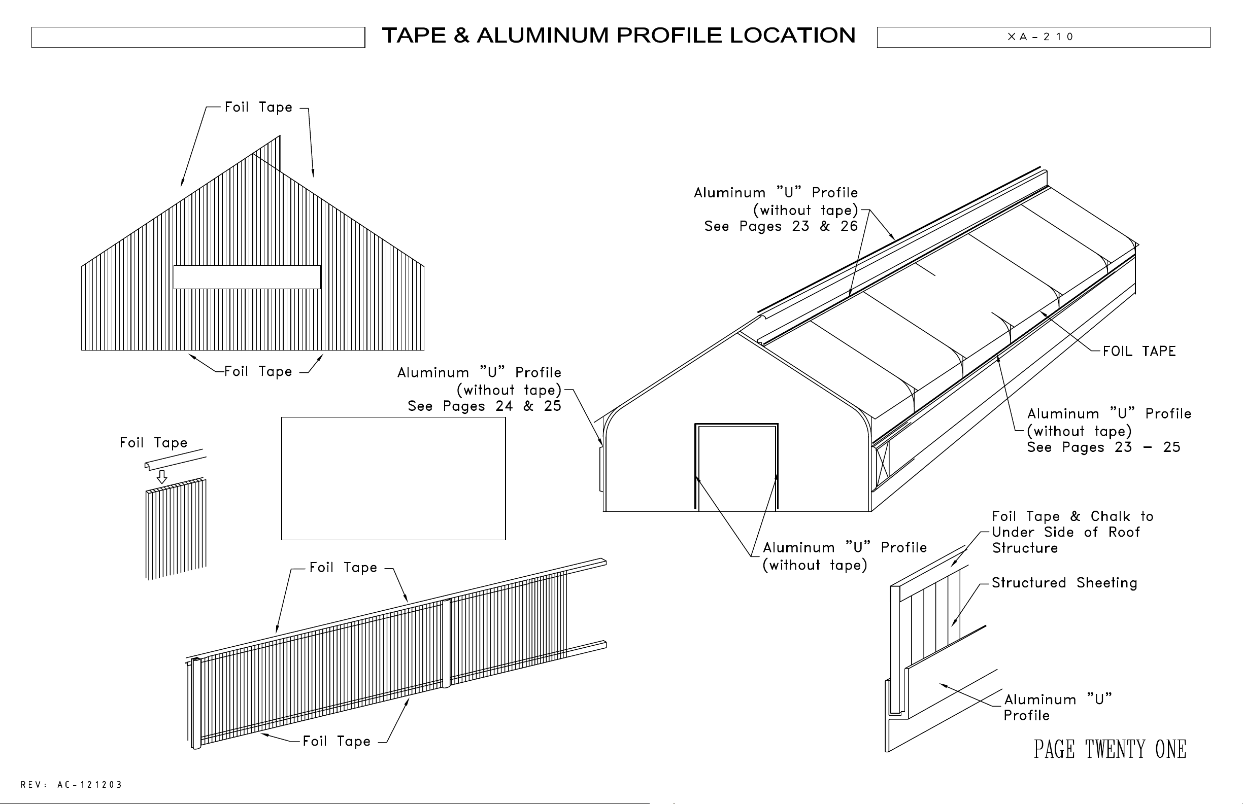
Structured Sheet Ends
(FOR STRUCTURED SHEETING APPLICATIONS)
For Structured
Sheet Roof
Note: Structured sheets are
supplied longer than required. Trim
to suit with min. 2" overhang at
eaves. Install all foil tape before
installing sheets to greenhouse
DO NOT APPLY FOIL TAPE UNTIL
ALL SHEETS ARE TRIMMED.
For Structured Sheet Skirting
along the bottom
Page 23
SA4014
S.A. DIVIDER
USE ALUMINUM "U" PROFILE
WITH STRUCTURED SHEETING
3
TOP ROLL
FORM RAIL
USE WIGGLE WIRE BASE
WITH (Polyethylene)
4
#12-14 x 1"
SELF DRILLING SCREW
SPACE AT 12" ALONG
ROLL FORM RAIL
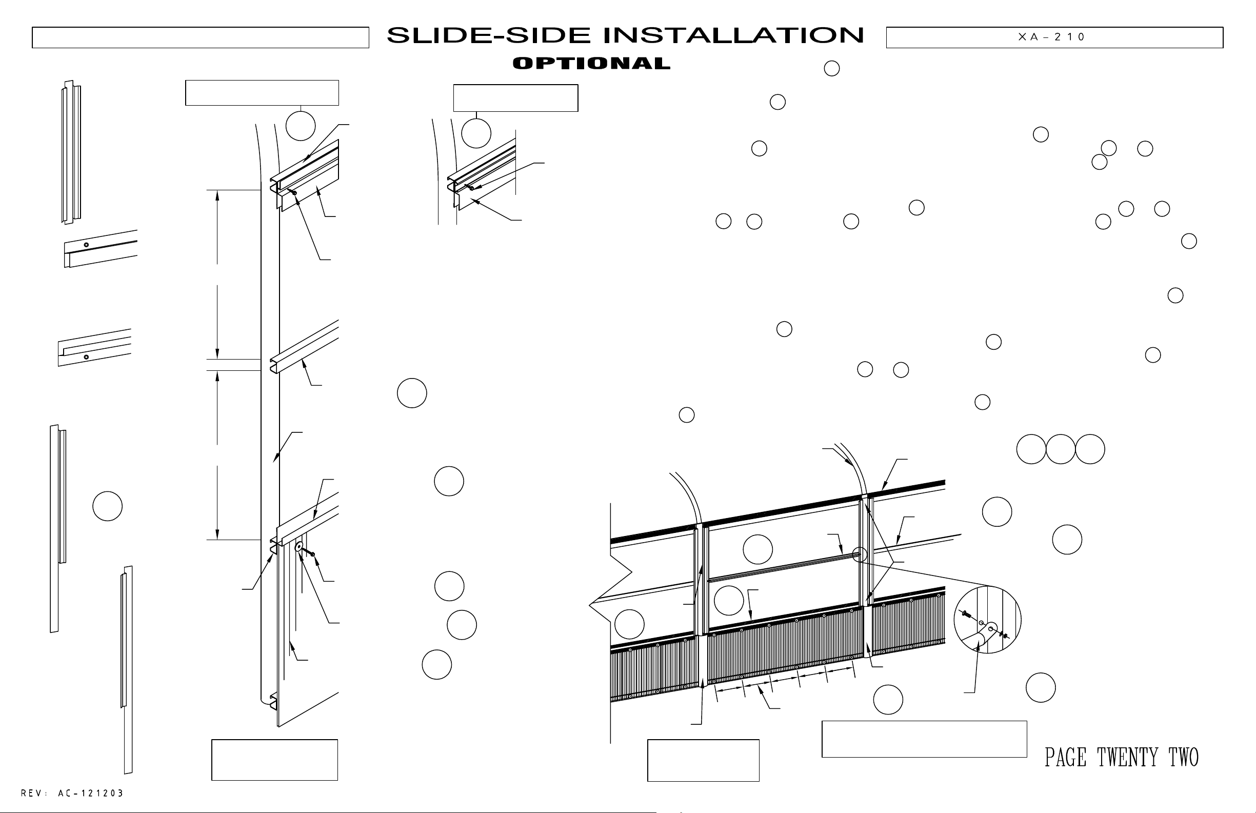
Install the center Roll Form Rail 1 at 22 1/4” above the second row of roll form using uni-clamps at each frame section
along the full length of the structure.
Install each Divider 2 by aligning with the center of each frame and holding flush with the top of the top Roll Form Rail.
Install one #12-14 x 1” self drilling screw into the center rail.
Beginning at one end of the structure, position one piece of the Aluminum Profile 3 (for structured sheets) or the Poly
Fastener Base 4 (for polyethylene membrane roof) above the dividers. Holding the selected 3 or 4 flush with the
end of the roll form, install a temporary screw to hold up the free end of the piece according to 5 in figure A. Install one
screw through the piece at the first divider. Proceed to install additional pieces along the whole side placingone screw into
each divider.
SU510
PREASSEMBLED 2"
SEAT & BACKER
(ENLARGED & NOT TO SCALE)
SU500
PREASSEMBLED 1"
SEAT & BACKER
(ENLARGED & NOT TO SCALE)
SA4016
S.A. END CAP
LEFT
22 1/4"
22 1/4"
PREASSEMBLED 2"
SEAT & BACKER
#12-14 x 1"
SELF DRILLING SCREW
SPACE AT 12" ALONG
ROLL FORM RAIL
CENTER ROLL
FORM RAIL
FRAME SECTION
PREASSEMBLED 1"
SEAT & BACKER
1
9
PREASSEMBLED 2"
SEAT & BACKER
Insert a section of Pre-assembled 2” Seat & Backer 6 between each two dividers and behind the 3 or 4 piece.
Secure 3 or 4 and the 2” backer 6 at the same time into the roll form behind with screws 7 at 12” on center.
Begin with a frame at approximately the middle of one side of the structure. Cut a panel of polycarbonate sheeting 8 the
length to reach from the top of the second roll form rail to grade. Position a section of Pre-assembled 1” Seat & Backer 9
over the top edge of the panel. Raise the assembly and slide the backer 9 between adjacent dividers until the visiblebottom
of the backer is flush with the bottoms of the divider flanges. Center the panel left to right until one side alignswith the
center of the frame post. Secure the panel and backer with #12-14x1” self drilling screws & neoprene washers 10 at 12”
on center.
Cut the 24” H-Profile 11 to the proper length and insert over the side of the panel. Proceed to install each adjacent panel
and backer until reaching one end of the structure. Install one screw 12 through the H-Profile and the bottomflangeof
each divider. Trim the last panel at each end, flush with the outside of the end post. Install S.A. End Cap 13 by
removing the temporary screw from the 3 or 4 piece and sliding the end cap behind the piece. Secure the end cap
with three screws into roll form rails on each face of the structure.
Install Slide Panels according to page 27 and attach the Slide-Bar 14 with ¼” x ¾” carriage bolts, lock washers, and nuts
15 through pre-drilled holes in the S.A. Divider 2. Be sure the head of the bolt faces the inside of the structure.
MIDDLE INTERMEDIATE
FRAME SECTION
PREASSEMBLED 2"
SEAT & BACKER
3
4
6
13
SA4017
S.A. END CAP
RIGHT
BOTTOM ROLL
FORM RAIL
CROSS-SECTION VIEW
FIGURE A
#12-14 x 1 1/2" SELF
DRILLING SCREW
NEOPRENE WASHER
STRUCTURED SHEET
8
5
10
S.A. DIVIDER
2
24" H-PROFILE
FIGURE B
ISOMETRIC VIEW
S.A. DIVIDER
SLIDE BAR
2
12
14
PRE-ASSEMBLED
1" SEAT & BACKER
(2) #12-14 x 1" SELF-DRILLING SCREWS
9
1/4" x 3/4" CARRIAGE
BOLT, LOCK WASHER,
24" H-PROFILE
"
6
"
6
12" (TYPICAL)
14
NOTE: SEE PAGE TWENTY-FOUR
BEFORE INSTALLING SHEETING.
SLIDE BAR
& HEX NUT
15
Page 24
Page 25
Page 26
Page 27
Page 28
( OPTIONAL )
Page 29
( OPTIONAL )
Page 30
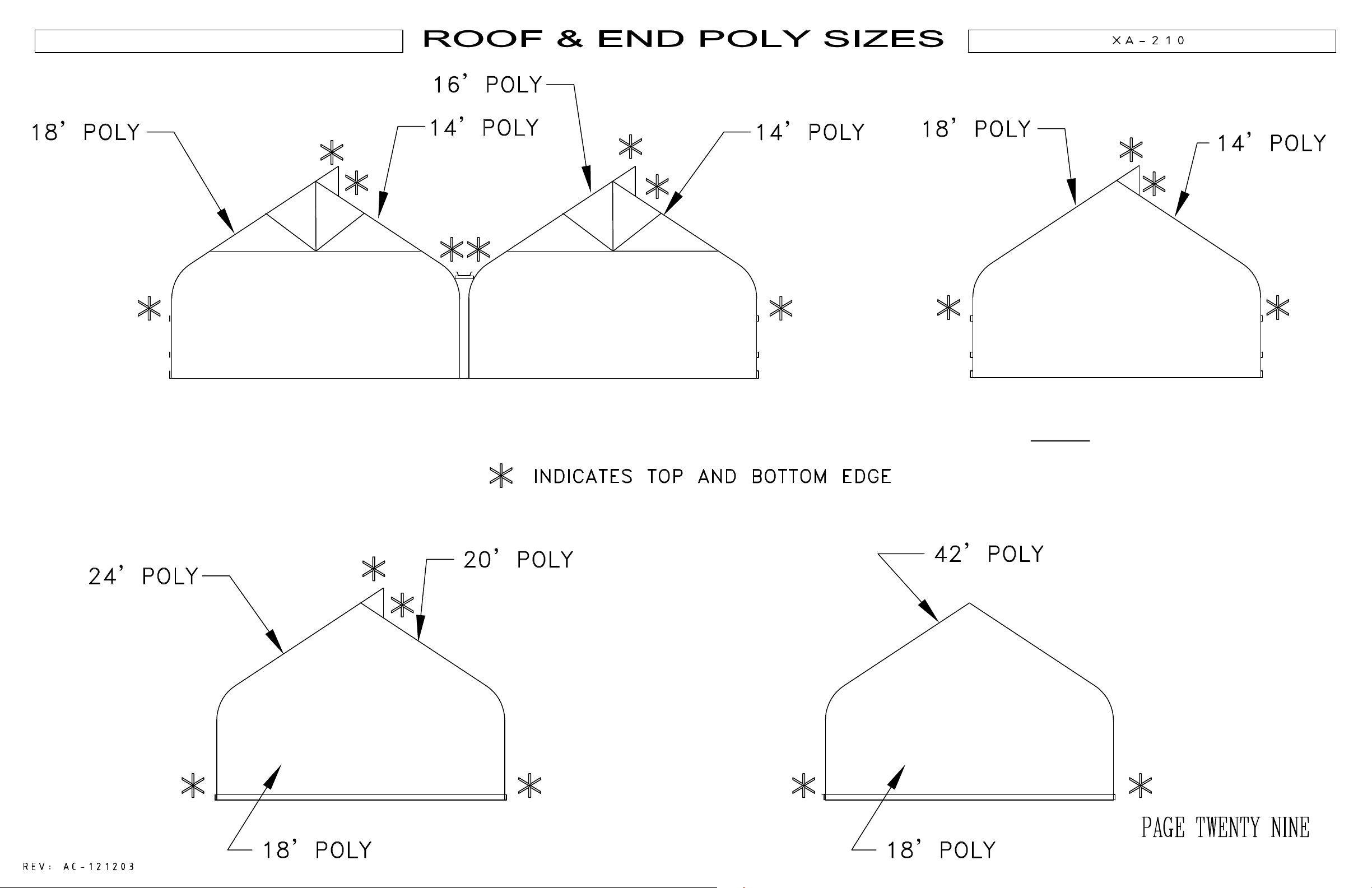
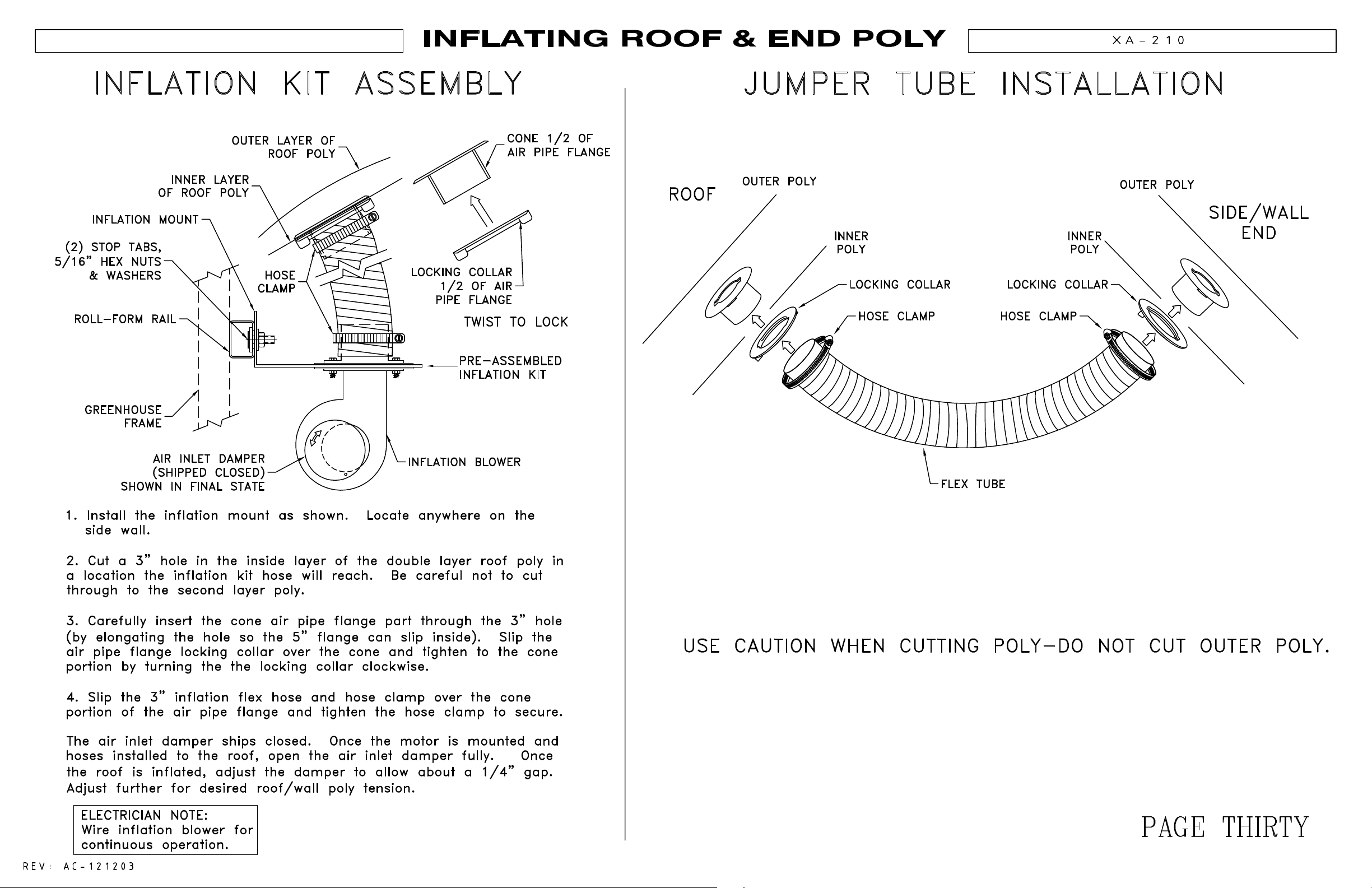
NOTE: Double Poly roof
membranes shall be tensioned so
that there remains about 8" - 9"
between membranes when inflated.
Page 31
Page 32
( OPTIONAL )
XXX XXX
XXX
XXX
XXX
XXX
XXX
XXX
XXX
XXX
XXX
XXX
 Loading...