

Page 1
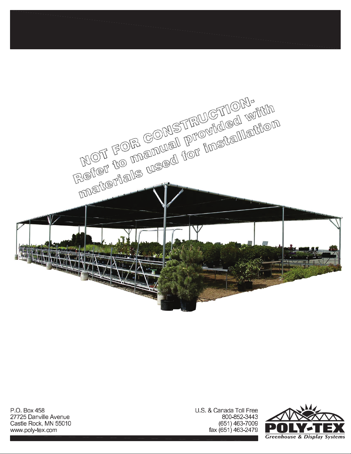
SUNSTOPPER shade structure system
INSTALLATION INSTRUCTIONS
REV: AE-131121
Page 2
SAFETY GUIDELINES
PLEASE READ THE INSTALLATION INSTRUCTIONS CAREFULLY BEFORE BEGINNING TO
ASSEMBLE THE STRUCTURE. SAVE THESE INSTRUCTIONS FOR FUTURE REFERENCE.
This structure is intended to be self-supporting, provided it is constructed with all frames,
hardware, sheathing, sheeting, bracing, cables, and membrane in place, and secured to the
foundation as shown in the manual. Stability during construction, from winds and loads imposed
during erection, is the sole responsibility of the installer. Observe safety codes required by the
local jurisdiction, and relevant safety practices for working at heights. Avoid the risk of electrical
shock from overhead lines or electrical storms. Poly-Tex recommends contracting a licensed
electrician to perform electrical work. Eye protection is recommended under all circumstances and
hearing protection is recommended when cutting components with power tools.
Foundations
These instructions include minimum guidance for foundations based on the International Building
Code. These minimums are suitable for some areas of the country but not all. Obtain a building
permit if required in the local jurisdiction. Engineered and Certified foundation plans may be
required by a building official before issuing a permit. Even if not required, seeking guidance from
a qualified structural or civil engineer for the foundation design may improve the life of the
structure.
No part of this structure is engineered to function as an anchorage point for a fall arrest system.
Use a safety net or work from a safe work platform (i.e. scaffolding). Select a calm day for work.
Wind can be sufficient enough to knock materials or workers off a work platform or ladder,
resulting in a potentially deadly fall.
Overview of assembly procedure
While each structure and site is unique, and may re
are for a tilt-up method (where frames are assembled on the ground and tilted onto ground
stakes or anchor rods using ropes or lifts). If installer is not confident to erect the structure, PolyTex suggests hiring a general contractor, carpenter, or similar licensed business familiar with
construction, to assemble and erect the structure.
quire special considerations, these instructions
Do not overload structure. Consult with a Poly-Tex representative prior to add
of weight over the specified capacity of this structure. Basket purlins, shelving or any objects of
significant weight shall not be hung, attached, or secured to roof or truss members in a manner
that will overload the structure.
ing any amount
Do not walk on polycarbonate sheets. If structure is to be covered with polycarbonate sheets,
always use scaffolding for the erection process to avoid
Polycarbonate sheeting has UV coating protected with vinyl film on the exterior surface. Install
sheets with the film intact and toward the exterior. Remove film once the sheet has been
fastened in place.
damage to sheeting and to ensure safety.
REV: AE-131121 REV AE-131121 131104 Safety Guidelines.docx
Page 3
SUNSTOPPER
Index
PART IDENTIFICATION
SITE PREPARATION
PIER FOUNDATION INSTALLATION
FRAME ASSEMBLY
CORNER & EDGE DIAGONAL BRACES
FOUR & THREE WAY DIAGONAL BRACES
DIAGONAL CABLE INSTALLATION
BUNGEE INSTALLATION
SHADE CLOTH INSTALLATION
Pg 1
Pg 2
Pg 3
Pg 4
Pg 5
Pg 6
Pg 7
Pg 8
Pg 9
REV: AE-131121
Page 4
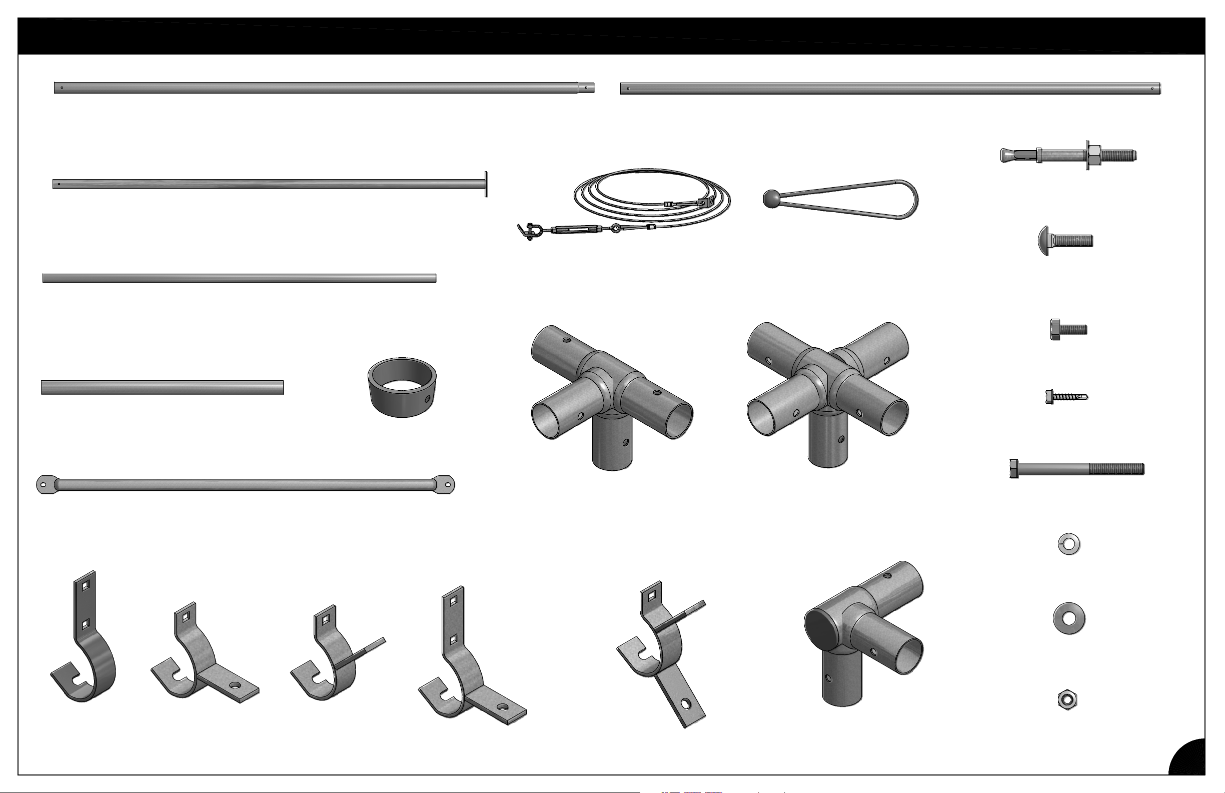
PARTS IDENTIFICATION
SH6000
2 1/2" x 120" W/SWAGE (SS)
SH6004
10' VERTICAL W/7" SQ BASE
ST2059
9'-8 1/2" VERTICAL POST (FOR GROUND STAKES)
9'-8 1/2" HORIZONTAL TUBE (IF REQUIRED BY STRUCTURE SIZE)
SH2006
CABLE ASSEMBLY
SH6001
2 1/2" x 120" PLAIN (SS)
NB1929
EXPANSION ANCHOR 3/8 x 3 3/4"
PT2521
BUNGEE BALL
NB1832
Ø5/16" x 1-1/4"
CARRIAGE BOLT
NB1842
Ø5/16" x 3/4" HEX BOLT
GS2404
GROUND STAKE (IF REQUIRED)
SU5064
1.315 x 46 1/2 DIAGONAL BRACE
FT2015
"G" FITTING
FT4003
3-WAY FITTING (SS)
FT4004
4-WAY FITTING (SS)
NB1806
SELF-DRILL SCREW 1/4-14x3/4"
NB1887
BOLT HEX 5/16" x 3-1/2" ZP
NB1862
LOCK WASHER 5/16" ZP
NB1886
5/16" FLAT WASHER
FT2081
LONG SPEED
HOOK (2-1/2")
REV: AE-131121
FT2083
2-WAY INLINE
SPEED HOOK
FT2082
2-WAY
SPEED HOOK
FT2085
3-WAY LONG SPEED
HOOK (2-1/2")
FT2089
SHORT SPEED HOOK (2 1/2) W/TABS
FT4026
CORNER FITTING (SS)
NB1872
HEX NUT 5/16" ZP
1
Page 5
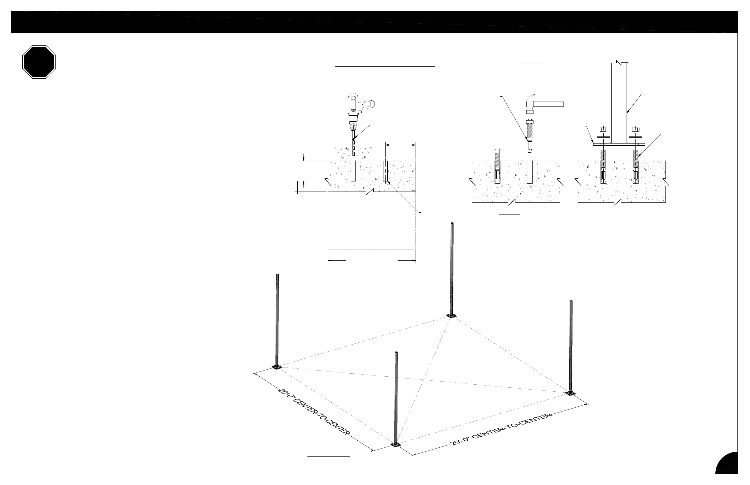
STOP
BEFORE STARTING INSTALLATION OF VERTICAL POSTS
PLEASE REFER TO CUSTOM LAYOUT SHEET THAT WAS
SENT WITH MANUAL. FAILURE TO FOLLOW CUSTOM
LAYOUT COULD RESULT IN HAVING A SHORTAGE OF
PARTS NEEDED TO COMPLETE THE SUNSTOPPER.
AS ACCURACY IN THIS PART OF THE WORK IS VERY
CRITICAL, PLEASE MAKE SURE THAT THIS PAGE IS
THOROUGHLY UNDERSTOOD BEFORE PROCEEDING.
TO SQUARE UP THE STRUCTURE, INSURE DIAGONAL
MEASUREMENTS ARE EQUAL. CHECK THE LAYOUT
MEASUREMENTS TO MAKE SURE THEY ARE CORRECT.
(CENTER-TO-CENTER OF BASE PLATES.) SEE FIGURE 1
FOR EXPANSIVE CLAYS OR SOILS IN EARTHQUAKE
ZONES, POLY-TEX RECOMMENDS CONTACTING A
GEOTECHNICAL OR STRUCTURAL ENGINEER FOR
FOUNDATION ENGINEERING.
SITE PREPARATION
BASE PLATE INSTALLATION
ON A SLAB
DRILL HOLE WITH
Ø3/8" CONCRETE
MASONRY BIT
3-1/2" MIN
HOLE DEPTH
2" MIN.
Provide 2,500 psi concrete, min. 4,000 psi with
INSTALL EXPANSION
ANCHORS.
PROVIDE A MINIMUM
3 3/4" TO EDGE
OF CONCRETE IN
ALL DIRECTIONS
Anchors
5% ± 1% air entrainment in frost zones.
BASE
VERTICAL POST
(SH2001)
(4) 3/8" GALVANIZED
EXPANSION ANCHORS
WITH 3 1/2"
MINIMUM EMBEDMENT
ALTERNATE:
Ø15" MINIMUM
CONCRETE PIER
STEP 1
BLOW OUT HOLE
TO REMOVE DEBRIS.
STEP 2
STEP 3
REV: AE-131121
FIGURE 1
2
Page 6
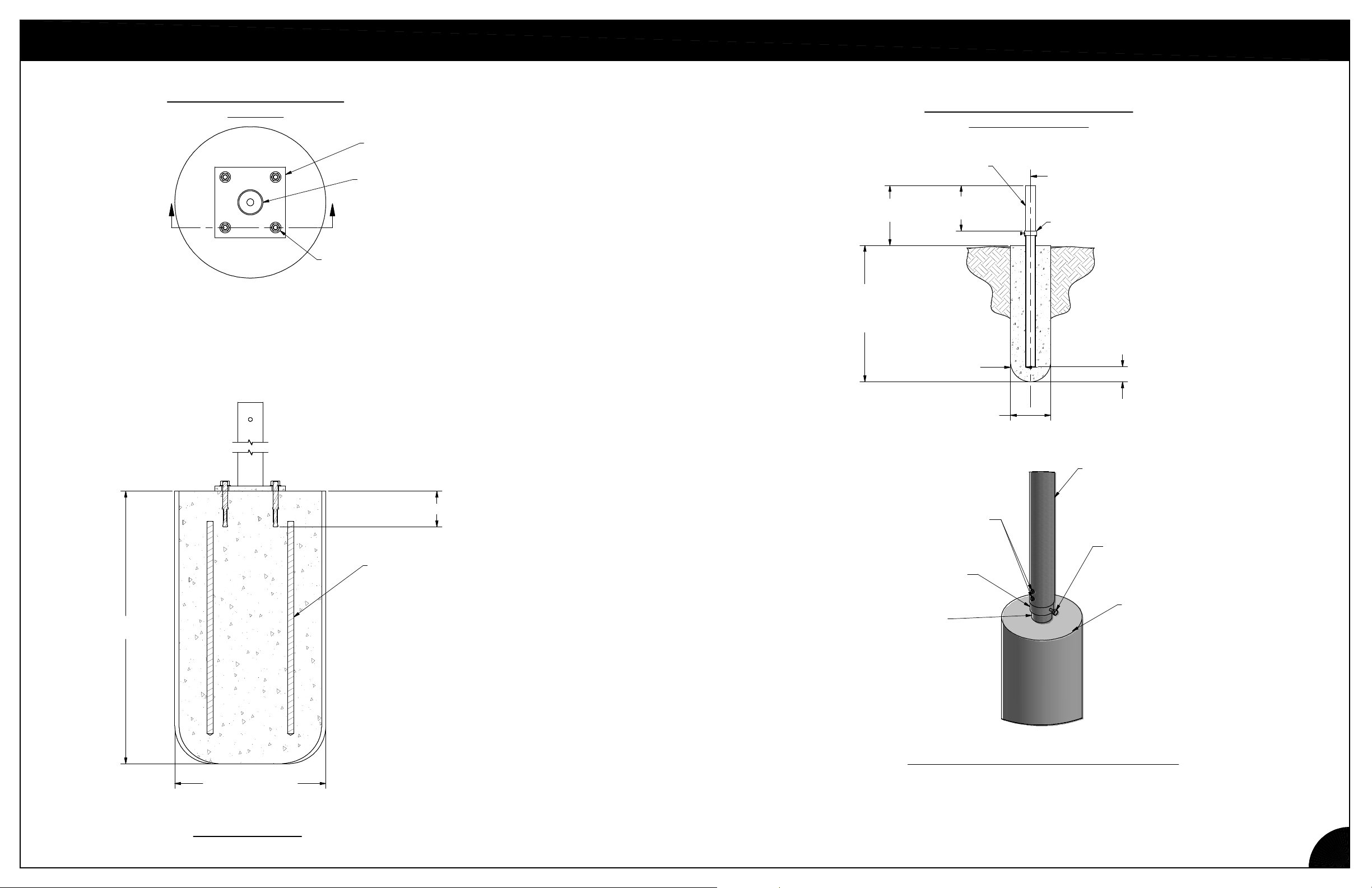
PIER FOUNDATION INSTALLATION
LEG STAND INSTALLATION
ON PIER
A A
NB1930 EXPANSION ANCHOR 1/2 x 4 1/2" (4)
FT1556
BASE PLATE 7x7x1/2 (11/16")
SH2022
9'-8 1/2" VERTICAL W/7"SQ BASE
GROUND STAKE
TOP OF
GROUND
STAKE
TOP OF
FOOTING
DEPTH OF FOOTING
TO CONFORM TO
LOCAL BUILDING CODES.
PROVIDE 27" MINIMUM.
12"
MAXIMUM
SIDE COVER
GROUND STAKE INSTALLATION
IN AUGERED PIER
GS2404
8"
MIN.
3" MIN
8" MIN
q GROUND STAKE, FOOTING
"G" FITTING FT2015
3" MIN
BOTTOM
COVER
24"
MINIMUM
15"
CONCRETE PIER
3-1/2" MINIMUM EMBEDMENT
#4 VERTICAL
REBAR (4)
(2) 1/4"-14 x 3/4" SELF-DRILLING SCREW NB1806
2" FROM TOP OF "G" FITTING
2" BETWEEN SCREWS
"G" FITTING FT2015
GROUND STAKE
IMPORTANT: DO NOT BYPASS THIS PROCEDURE
After the SunStopper vertical posts are installed,
1/4"-14 x 1" self-drilling screws through the wall of EACH
post and into the ground stake for a secure anchor.
VERTICAL POST
Ø5/16" x 3/4"
HEX BOLT
NB1842
FOOTING
install two
REV: AE-131121
SECTION A-A
3
Page 7
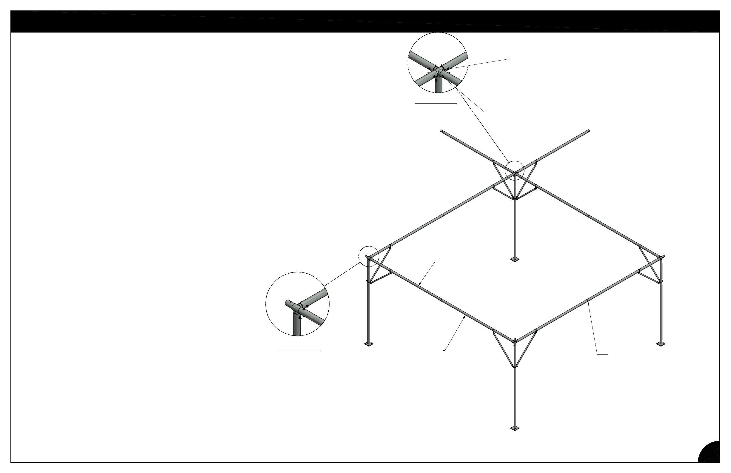
FRAME SETUP
Set up the frame using the fittings included with the parts, the Corner Fitting FT4026, the 3-way
Fitting FT4003,and the 4-way Fitting FT4004 if applicable. If installing a 40' x XX' SunStopper,
there will be (a) 4-way fitting(s) included in the bag of parts. The 4-way fitting is used to join
larger structures together and is not required on a 20' x XX' structure.
For a Ground Stake application, connect the proper fitting on top of each
ST2059 Vertical and bolt fitting in place with a Ø5/16" X 3 1/2" Hex Bolt (NB1887),
5/16" Lock Washer (NB1862), and 5/16" Hex Nuts (NB1872). Tighten securely
and set the assembly on the stake. See Page 3 for attachment after Horizontals
have been connected*.
For the Base Plate option, place proper fitting on the top
of each SH6004 and position per drawing. Bolt fitting in place with a
Ø5/16" X 3 1/2" Hex Bolt (NB1887), 5/16" Lock Washer (NB1862),
and 5/16" Hex Nuts (NB1872). See Page 2 for Base Plate installation information.
Use 3-way fittings FT4003 at corners and edges.
*Connect two Horizontals, SH6000 & SH6001, with Ø5/16" X 3 1/2" Hex Bolt (NB1887), 5/16"
Flat Washer (NB1886) on one side of connection, 5/16" Flat Washer (NB1886) 5/16" Lock
Washer (NB1862), and 5/16" Hex Nuts (NB1872) in this order. Bolt heads should be to the
outside. Tighten securely (FIGURE 1). Install assembly by inserting
into adjacent fittings and bolt as above.
For structures 40' X 40' and larger, install (a) 4-way fitting(s) at interiors connecting to one
vertical post, using Ø5/16" X 3 1/2" Hex Bolts (NB1887), 5/16" Lock Washers
(NB1862), and 5/16" Hex Nuts (NB1872). Tighten securely (FIGURE 2).
FT4004
4-WAY FITTING (SS)
If structure is larger than 20' x 20'
FIGURE 2
Hex Bolt (NB1887)
5/16" Lock Washers (NB1862)
and 5/16" Lock Nuts (NB1872) typ.
SH6000
2 1/2" x 120" W/SWAGE (SS)
REV: AE-131121
FIGURE 1
SH6001
2 1/2" x 120" PLAIN (SS)
Ø5/16" X 3 1/2" Hex Bolt (NB1887)
5/16" Flat Washer (NB1886)
on one side of connection
5/16" Flat Washer (NB1886)
5/16" Lock Washer (NB1862)
and 5/16" Hex Nut (NB1872)
4 Places
4
Page 8
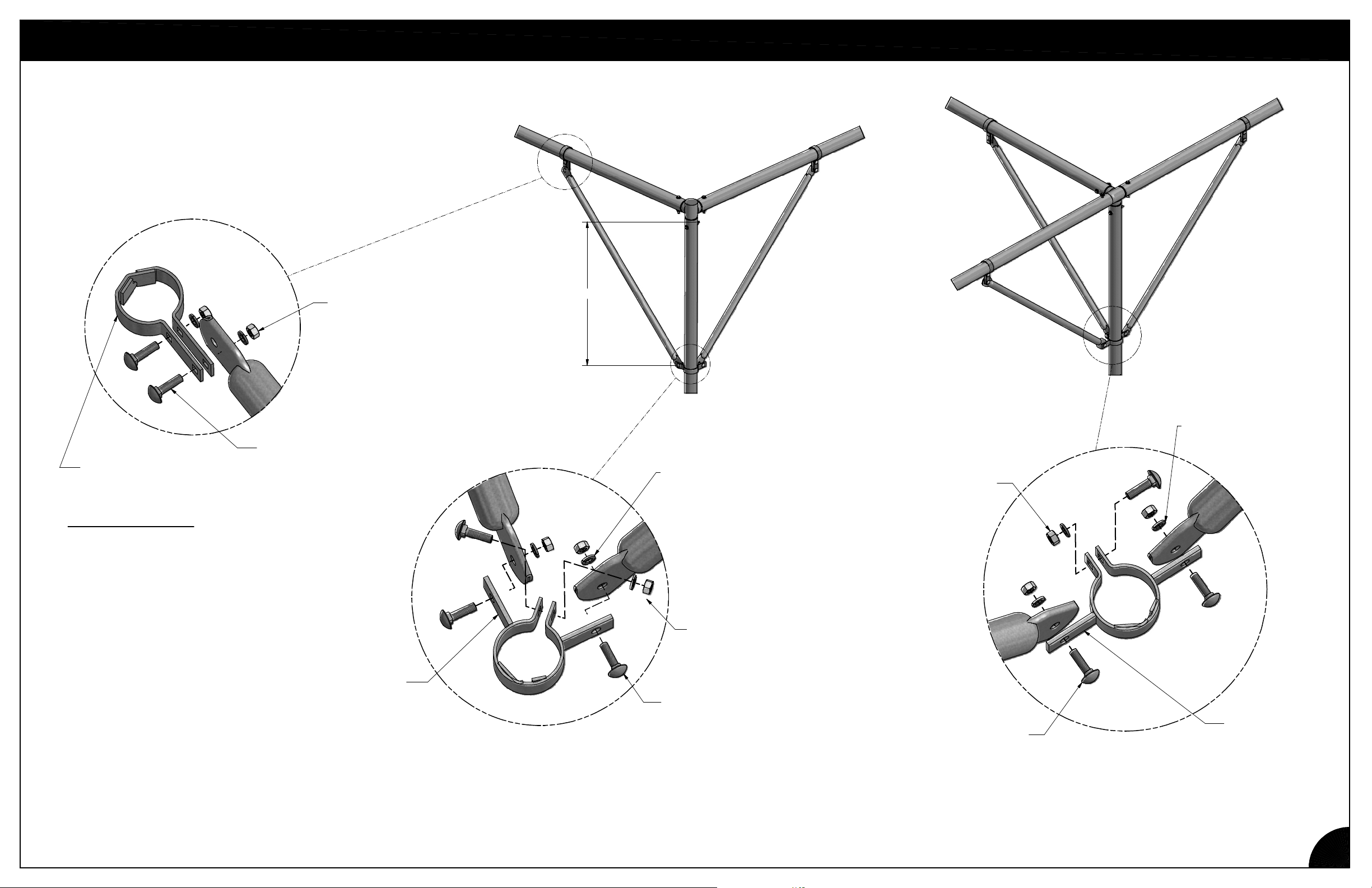
The placement of the diagonal braces depends
upon the size and shape of your structure.
Refer to custom layout that was sent along with
the manual. Install diagonal braces where layout
dictates to ensure proper support of structure.
"Bottom" Speed Hooks should be located
approximately 33" down from top of Vertical post
so Diagonal Braces are at or near 45 degrees.
CORNER & INLINE DIAGONAL BRACES
HEX NUT
NB1872 (2)
CARRIAGE BOLT
LONG SPEED
HOOK FT2081
(2)
IMPORTANT NOTE
ALL COMPONENTS ATTACHED TO LONG
SPEED HOOKS MUST BE MOUNTED ON THE
OUTSIDE OF THE HOOKS. NEVER INSTALL
COMPONENTS BETWEEN HOOKS.
NB1832 (2)
33" TYP.
LOCK WASHER 5/16" ZP
NB1862 (3)
LOCK WASHER 5/16" ZP
NB1862 (3)
HEX NUT
NB1872 (3)
REV: AE-131121
2-WAY
SPEED HOOK
FT2082 (2)
HEX NUT
NB1872 (3)
CARRIAGE
BOLT
NB1832 (3)
CARRIAGE
BOLT
NB1832 (3)
2-WAY INLINE
SPEED HOOK
FT2083 (2)
5
Page 9
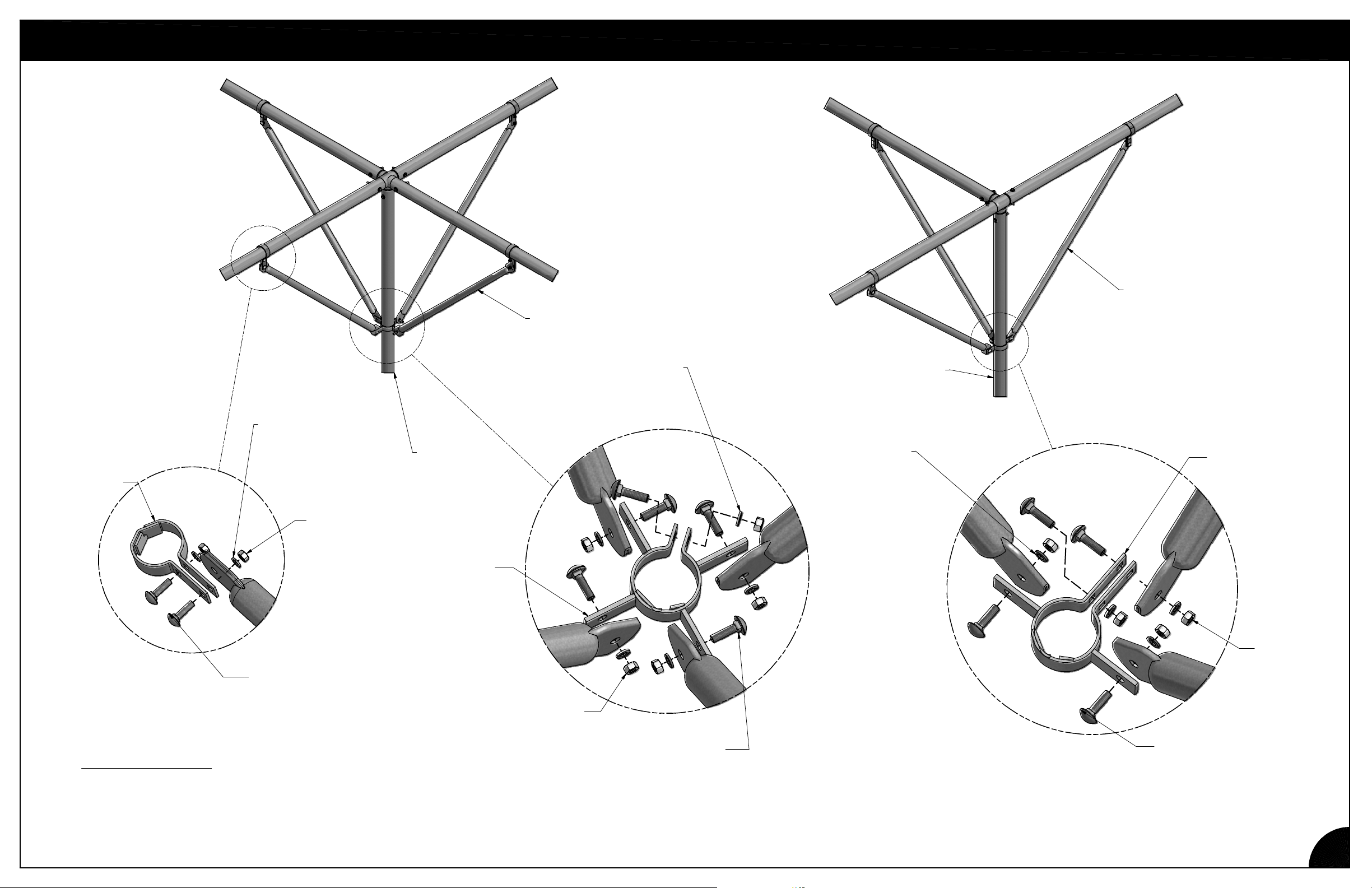
FOUR & THREE-WAY DIAGONAL BRACES
SU5064
1.315 x 46 1/2 DIAGONAL BRACE
SU5064
1.315 x 46 1/2 DIAGONAL BRACE
LONG SPEED
HOOK
FT2081 (2)
IMPORTANT NOTE:
ALL COMPONENTS ATTACHED TO LONG
SPEED HOOKS MUST BE MOUNTED ON THE
OUTSIDE OF THE HOOKS. NEVER INSTALL
COMPONENTS BETWEEN HOOKS.
LOCK WASHER
NB1862 (2)
HEX NUT
NB1872 (2)
CARRIAGE
BOLT
NB1832 (2)
ST2059
2.5" x 116.5 "
x 12GA Gator
SHORT
SPEED HOOK
(WITH TABS)
FT2089 (2)
HEX NUT
NB1872 (5)
LOCK WASHER
NB1862 (2)
CARRIAGE
BOLT
NB1832 (5)
ST2059
2.5" x 116.5 "
x 12GA Gator
LOCK WASHER
NB1862 (2)
3-WAY LONG
SPEED HOOK
FT2085 (2)
HEX NUT
NB1872 (4)
CARRIAGE
BOLT
NB1832 (4)
REV: AE-131121
6
Page 10
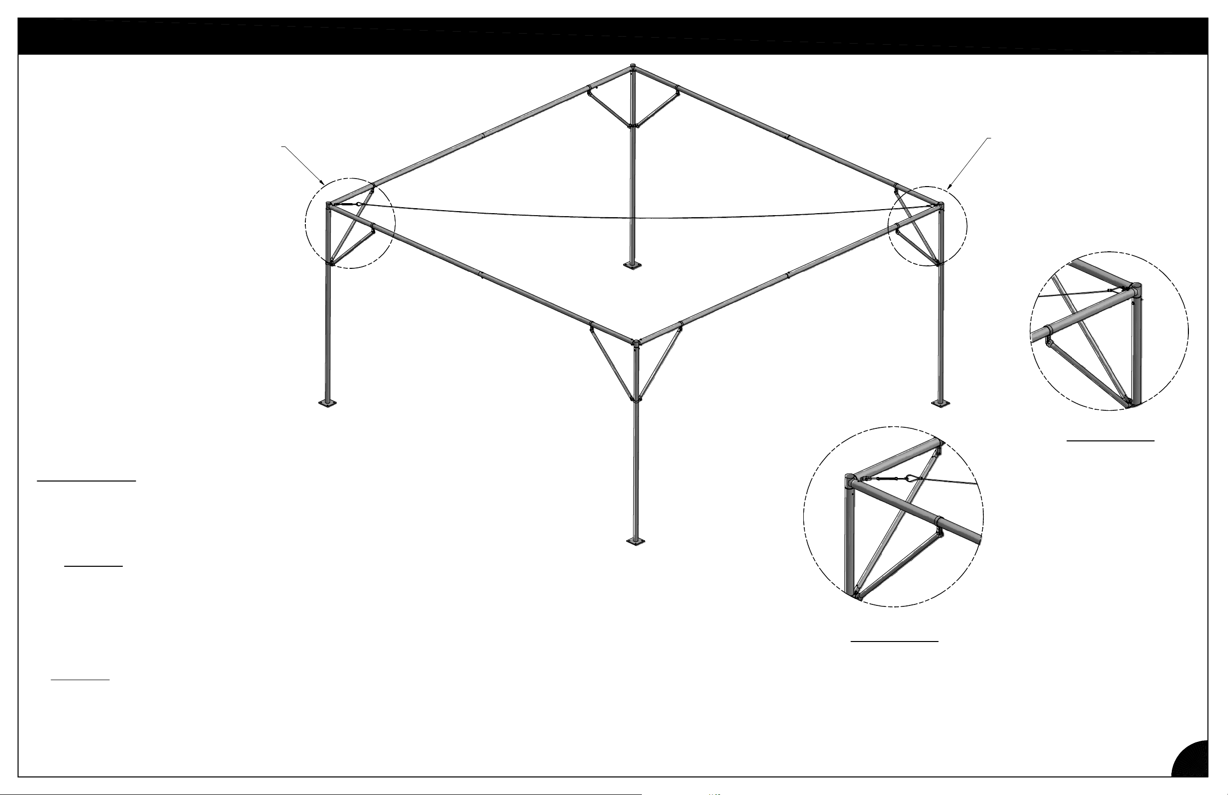
DIAGONAL CABLE INSTALLATION
SEE FIGURE 2
SEE FIGURE 1
8" "Sag"
INSTRUCTIONS:
1. Remove one Ø5/16" Hex Nut from the inside of one corner fitting (FIGURE 1).
Do not discard.
2. Attach the bracket on the non-turnbuckle end of the cable assembly to the top fitting as shown
in FIGURE 1 using the Ø5/16" x 3-1/2" long Hex Bolt and replace Nut and Washer.
3. Unscrew the turnbuckle to make the cable assembly as long as possible.
4. Remove one Ø5/16" Hex Nut from the inside of the corner fitting on the opposite corner
of the 20' x 20' section.
5. Attach the bracket on the turnbuckle end of the cable assembly to the top fitting as shown in
FIGURE 2
6. Tighten the cable assembly with the turnbuckle until the cable has about an 8" sag.
using the previously removed Ø5/16" x 3-1/2" long
Hex Bolt and replace Nut and Washer.
FIGURE 1
FIGURE 2
REV: AE-131121
7
Page 11
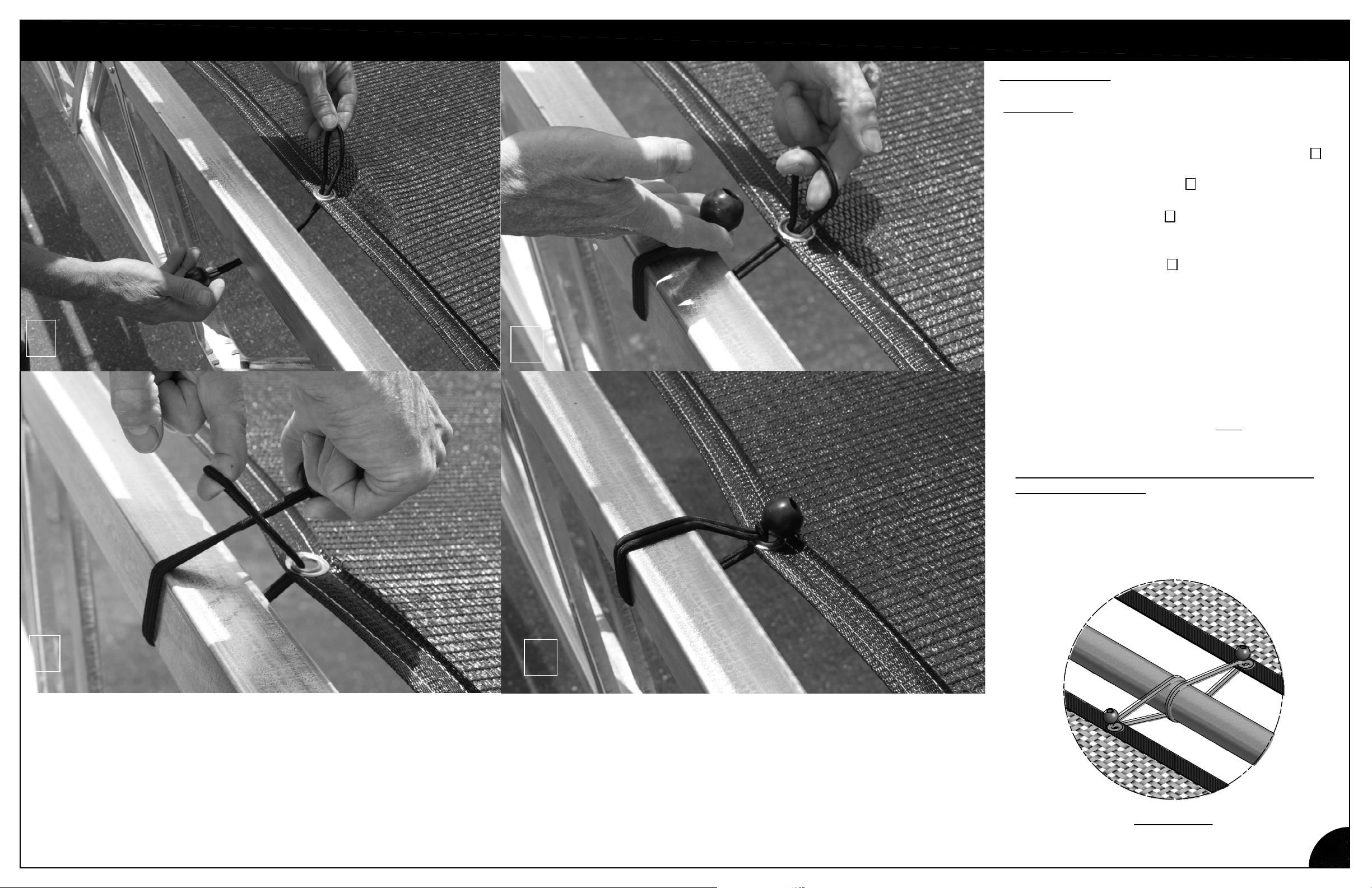
1
BUNGEE INSTALLATION
2
INSTRUCTIONS:
CAUTION:
INSTALLING BUNGEE CORDS.
1. Insert Bungee Cord through Grommet in fabric.
2. Wrap cord around support.
3. Insert ball through loop.
4. Once in place, move Bungee so that ball is over
the Grommet as shown.
5. A Bungee may slip off if not installed properly.
Occasionally check installation to insure that all
Bungee Cords remain attached.
6. When re-installing, inspect Bungee balls for
wear or damage.
Do not use damaged Bungee Balls!
7. For adjacent shade panels, use only
Bungee Ball per Grommet as shown in
FIGURE 5.
DO NOT USE ONE BUNGEE BALL FOR TWO
GROMMET HOLES.
WEAR EYE PROTECTION WHEN
2
3
4
one
1
3
REV: AE-131121
4
FIGURE 5
8
Page 12
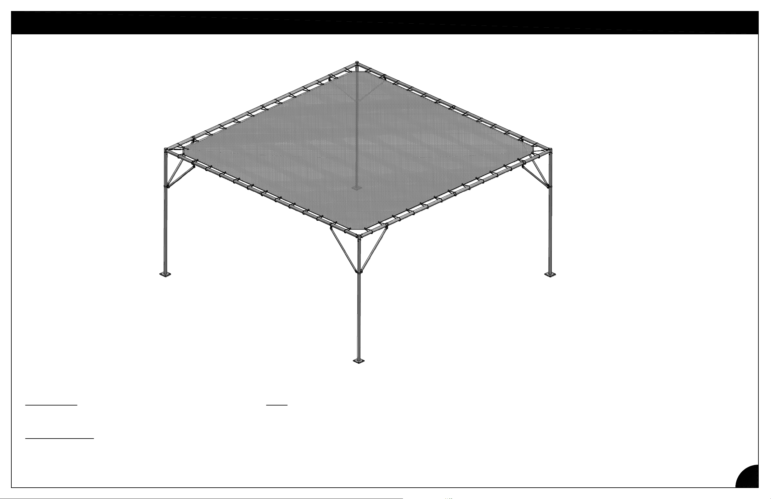
SHADE CLOTH INSTALLATION
WARNING: This product was not designed to support
Be sure all chances of snow accumulation have passed before installing the
shade cloth. If, by chance, snow does accumulate on top of the shade cloth,
IMMEDIATELY
snow to fall to the ground.
REV: AE-131121
remove the bungee balls securing the shade cloth to allow
ANY
amount of snow.
9
Page 13

SAFETY GUIDELINES
Do not climb, sit on, or use this product as a ladder. Injuries may occur.
Do not place or install electrical items on this product. Electric shock may occur.
Do not place this product on a slope that exceeds 1/4" per foot.
Do not overload structure with hanging plants that weaken the structure's resistance to wind.
CARE & MAINTENANCE
Periodically (at least every two years) inspect items subject to wear for signs of deterioration,
weakening, or significant corrosion.
Limited Warranty
Poly-Tex, Inc. warrants its products to be free from defects in material and workmanship for a
period of (1) year from date of invoice. This warranty is provided to the original purchaser of the
product and is not transferable. Poly-Tex does not warrant parts not manufactured by Poly-Tex,
but does assign any transferable manufacturer or supplier warranties. Should any defect be
found, full repair or replacement will be rendered to the customer at no cost following inspection
by a Poly-Tex representative and the return of the defective product to our Castle Rock, MN
factory. Expenses for removal or reinstallation of defective products will not be covered by the
warranty.
POLY-TEX SHALL NOT BE HELD RESPONSIBLE FOR ANY SPECIAL OR
CONSEQUENTIAL DAMAGES, OR FOR ANY DELAY IN PERFORMANCE OF THIS
WARRANTY BEYOND OUR CONTROL. THIS WARRANTY IS EXCLUSIVE AND IN LIEU OF
ALL OTHER WARRANTIES WHETHER IMPLIED, WRITTEN OR ORAL INCLUDING THE
WARRANTIES OF MERCHANTABILITY AND FITNESS FOR A PARTICULAR PURPOSE.
This warranty does not cover damage from customer abuse, misuse, improper installation,
customer modifications, customer negligence in performing normal maintenance, damage
resulting from acts of nature.
Contact information
Poly-Tex, Inc. PO Box 458
27725 Danville Ave Castle Rock, MN 55010
Toll free (800) 852-3443 Fax (651) 463-2479
www.poly-tex.com
 Loading...