


Title
Advanced Test Equipment Rentals
www.atecorp.com 800-404-ATEC (2832)
®
E
s
t
a
b
l
i
s
h
e
d
1
9
8
1
User Manual
Laser Doppler Vibrometer
Controller OFV-3001
Sensor Heads OFV-303/-353
OFV-511/-512

Warranty and Service
The warranty for this eq uipmen t com plies with the regul ations in our gener al terms an d
conditions in thei r r es pecti ve val id v er sion .
This is conditiona l on the equ ipmen t bein g used as it is in tende d and as desc ribe d in this
manual.
The warranty does not apply to dam age caus ed by in correct usa ge, ex terna l mechani cal
influences or by not keeping to the operating conditions. The warranty also is invalidated in the
case of the equipme nt being tampere d with or m odified wi thout aut horiza tion .
To return the equipme nt always use the origina l packagi ng. Other wise we r eserve th e righ t to
check the equipment for transport damage. Please mark the package as fragile and sensitive to
frost. Include an explanation of the re ason for returning it as wel l as an exact description o f t he
fault. You can find advi ce on fa ult diag nosis in c hap ter 6.
Trademarks
Brand and product na mes ment ioned i n this ma nual could be trade marks or reg istere d
trademarks of th eir respe ctiv e companie s or organi zation s.
Identification Labels
Controller Sensor Head

Contents
Contents
1 Safety Information 1-1
1.1 Laser Safety .......................................................................................................................1-1
1.2 Laser Warning Labels......................................................................................................... 1-2
1.2.1 EC Countries ............................................................................................................ 1-2
1.3 Laser Warning Labels.........................................................................................................1-4
1.3.1 Non-EC Countries..................................................................................................... 1-4
1.4 Electrical Safety..................................................................................................................1-6
2 Introduction 2-1
2.1 System Overview................................................................................................................2-1
2.2 Component Summary .........................................................................................................2-2
3 First Steps 3-1
3.1 Operating and Maintenance Requirements ......................................................................... 3-1
3.2 Unpacking and Inspection...................................................................................................3-2
3.3 Control Elements of the Vibrometer .................................................................................... 3-3
3.3.1 Controller.................................................................................................................. 3-3
3.3.2 Sensor Head OFV-303.............................................................................................. 3-7
3.3.3 Sensor Head OFV-353.............................................................................................. 3-8
3.3.4 Sensor Head OFV-511.............................................................................................. 3-9
3.3.5 Sensor Head OFV-512.............................................................................................3-11
3.4 Installation and Functional Test ......................................................................................... 3-13
3.4.1 Vibrometer with Sensor Head OFV-303/-353........................................................... 3-13
3.4.2 Vibrometer with Sensor Head OFV-511/-512........................................................... 3-14
4 Making Measurements 4-1
4.1 Start-up...............................................................................................................................4-1
4.1.1 Vibrometer with Sensor Head OFV-303/-353.............................................................4-1
4.1.2 Vibrometer with Sensor Head OFV-511/-512.............................................................4-2
4.1.3 Displaying the Output Signals ................................................................................... 4-3
4.2 Selecting Suitable Settings .................................................................................................4-4
4.2.1 Velocity or Displacement Measurement? ..................................................................4-4
4.2.2 Settings for Velocity Measurement............................................................................4-5
4.2.3 Settings for Displacement Measurement (optional) ................................................. 4-10
4.2.4 Optimal Stand-Off Distances for the Sensor Heads................................................. 4-14
i

Contents
5 Operating the Vibrometer 5-1
5.1 Switching On and Off ...........................................................................................................5-1
5.2 Beam Shutter and Emission Indicator..................................................................................5-1
5.3 Signal Level Display ............................................................................................................5-2
5.4 Focusing the Laser Beam....................................................................................................5-2
5.5 Exchanging the Front Lens..................................................................................................5-4
5.6 Making Single Point Measurements with the Sensor Head OFV-512 ...................................5-5
5.7 Fixing the Focus (only OFV-353).........................................................................................5-5
5.8 Transport Safety Mechanism (only OFV-511/-512)...............................................................5-6
5.9 Operating the Vibrometer via the Display of the Controller...................................................5-7
5.9.1 Operating Philosophy.................................................................................................5-7
5.9.2 Organization of the Menus.........................................................................................5-8
5.9.3 The Individual Menus .................................................................................................5-9
5.10 Setting Measurement Ranges and Filters ........................................................................5-11
5.11 Displaying the Configuration of the Controller ..................................................................5-11
5.12 Configuring the Interfaces................................................................................................5-11
6 Fault Diagnosis 6-1
6.1 General Tests......................................................................................................................6-1
6.2 No Laser Beam....................................................................................................................6-2
6.3 No Measurement Signal ......................................................................................................6-3
6.4 Checklist for Fault Diagnosis ...............................................................................................6-5
6.4.1 Controller OFV-3001 with the Sensor Head OFV-303/-353 ........................................6-5
6.4.2 Controller OFV-3001 with the Sensor Head OFV-511/-512.........................................6-6
7 Technical Specifications 7-1
7.1 Controller OFV-3001............................................................................................................7-1
7.1.1 General Data .............................................................................................................7-1
7.1.2 Interfaces...................................................................................................................7-1
7.1.3 Low Pass Filter..........................................................................................................7-2
7.1.4 Signal Voltage Output VELOCITY OUTPUT...............................................................7-2
7.1.5 Signal Voltage Output DISPLACEMENT OUTPUT (optional) .....................................7-5
7.2 Sensor Head OFV-303/-353 ................................................................................................7-6
7.2.1 General Data .............................................................................................................7-6
7.2.2 Optics........................................................................................................................7-6
7.3 Sensor Head OFV-511/-512.................................................................................................7-8
7.3.1 General Data .............................................................................................................7-8
7.3.2 Optics........................................................................................................................7-8
Appendix A: Optional Accessories for the Sensor Head OFV-30 3/-35 3
Appendix B: Optional Accessories for the Sensor Head OFV-511/-512
Appendix C: Basics of the Measurement Procedure
Appendix D: Functional Description of the Cont roller
Appendix E: Interface Operation RS-232 and IEEE-488/GPIB
ii

1 Safety Information
1.1 Laser Safety
The light source of the vibrometer is a helium neon laser. It is important to
understand that laser light has different properties than ordinary light sources.
Laser radiation is genera lly extr emely intense due to th e beam 's low
divergence and gr eat care sh ould be taken when hand ling laser instrume nts
that the direct or re flec ted bea m does no t ente r the ey e. To ensure this , the
following precauti ons have bee n taken:
•
In general, Polytec equipm ent comp lies with t he standards
(DIN VDE 0837) and
•
The optical output of the laser is less than 1mW for the sensor heads
OFV-303/-353
manner for which it was in tende d. This mea ns that th e vibrom eter
conforms with
optimally focused, the laser radiation is not intense en ough to har m the
skin.
•
The optical output of the laser is less than 5mW (<1mW per fibre) f or the
sensor head
which it was intended. T his mea ns that th e vibrome ter confo rms with
laser class 3R (IIIa)
focused, the lase r radi ation is not inten se enou gh to ha rm the sk in.
•
The sensor head has bee n equippe d with a
used to block t he l as er b eam du ring t he w arm -up pha se or whe n th e
vibrometer is not in us e, a ltho ugh s witc hed on.
•
The
emission indica tor
laser and thus pote ntial ha rm cause d by emit ted lase r beams .
•
The beam shutt er is alway s
laser beam. Special editions of th e fibe r optica l sensor he ads wit h fiber
lengths of 3m are fitted wi th an addi tion al e m ission in dic ator w hich is
integrated in th e fibe rs.
•
The laser is switched on via a
only be removed when th e control ler is swit ched off.
•
It is
not necessary to open
the vibrometer as intend ed. Ope ning the housing wi ll invalidat e the
warranty.
CFR 1040.10
and
OFV-511
laser class 2 (II)
OFV-512
providing the eq uipment i s used in the mann er for
and is generally very sa fe. Ev en when opti mally
on the sensor head ind icates the ac tivity of the
1 Safety Information
EN 60825-1
(US).
providing the equi pment is us ed in the
and is generally very sa fe. Even wh en
beam shutter
less then 2m away
key switch
on the controller. The key can
from the apertu re of th e
which can be
the housing of the senso r head whe n using
Please pay attention
to the following
safety precau ti ons
when using the
vibrometer:
•
Never look directly int o the lase r beam with the nake d eye or with the aid
of mirrors or op tic al i nstr ume nts!
•
Only switch the beam shut ter to the ON pos ition when yo u are mak ing
measurements!
•
To position the sensor head, switch the beam shutter to the OFF position.
Only when the sensor he ad is rough ly in pla ce and has bee n fixe d in a
stable position, switch t he beam sh utter t o ON.
•
Do not use any reflective t ools, watch es etc. whe n you are working i n the
path of the laser beam!
1-1

1 Safety Information
1.2 Laser Warning Labels
1.2.1 EC Countries
Warning
labels
The laser warning labels for th e sensor heads in EC coun tries ar e shown in
figure 1.1. Label 2, 3 and 4 are affixed or encl os ed i n the la nguag e of t he
customer’s country . Their position on the sensor head OFV-303/-353 is shown
in figure 1.2 and on the sensor head OFV-511 resp. OFV-512 in figu re 1.3.
Laser class 2 for
OFV-303/-353 and OFV-511
Laser class 3R for
OFV-512
1
2
3
4
Figure 1.1: Laser warning label s for th e vibrometer in EC count ries
1-2

1 Safety Information
Position
The position of th e laser war ning lab els in E C count ries on th e senso r head
OFV-303/-353 is shown in figure 1.2.
1
3
B e a m
2 4
Figure 1.2: Position of t he la ser war ning l abels o n the sensor head OFV-303/ -353 in EC
countries
The position of th e laser war ning lab els in E C count ries on th e senso r head
OFV-511 resp. OFV-512 is shown in figure 1.3.
For the sensor head OFV-511, label 3 is affixed inside.
For the sensor head OFV-512, label 4 is affixed inside and label 3 is enclosed
with the sensor hea d as it is not pos sible to affix it on the mini senso r due to
its size. Please affi x thi s la bel c le arly visi ble near th e mo un te d mi ni s ens or or
fiber head.
1
A C H T U N G !
B i t t e v o r d e m T r a n s p o r t
d i e T r a n s p o r t s i c h e r u n g b e t ä t i g e n
S I G N A L
P R O C E S S O R
M E A S U R E M E N T
B e a m
Figure 1.3: Position of the laser war ning labels on t he senso r he ad OFV-511/-512 in EC countries
C A U T I O N !
P l e a s e s e c u r e t r a n s p o r t m e c h a n i s m
b e f o r e s h i p m e n t
2
T R A N S P O R T
1-3

1 Safety Information
1.3 Laser Warning Labels
1.3.1 Non-EC Countries
Warning labels
The laser warnin g l abels for the sensor heads i n non-EC countries are shown
in figure 1.4. Their position on the sensor head OFV- 303/-3 53 is shown in
figure 1.5 and on the sensor head OFV-511 resp. OFV-512 in figure 1.6.
Laser class II for
OFV-303/-353 and OFV-511
Laser class IIIa for
OFV-512
1-4
Figure 1.4: Laser warning
labels for the vibrometer in non-EC
countries

1 Safety Information
Position
The position of th e laser war ning lab els in non -EC coun tries on the sens or
head OFV-303/- 353 is s how n in figure 1.5.
3
B e a m
Figure 1.5: Position of the laser warning labels on the sensor head OFV-303/-353 in non-EC
countries
1 4 2
The position of th e laser war ning lab els in non -EC coun tries on the sens or
head OFV-511 resp. OFV-512 is shown in figure 1.6.
Label 4 is affixed inside. Labe l 3 is enclosed with th e senso r head as it is not
possible to affix it on the mi ni sensor due to its size. Pleas e affix this lab el
clearly visible near the moun ted m ini sens or or fibe r head.
1
A C H T U N G !
B i t t e v o r d e m T r a n s p o r t
d i e T r a n s p o r t s i c h e r u n g b e t ä t i g e n
S I G N A L
P R O C E S S O R
M E A S U R E M E N T
C A U T I O N !
P l e a s e s e c u r e t r a n s p o r t m e c h a n i s m
b e f o r e s h i p m e n t
T R A N S P O R T
B e a m
2
Figure 1.6: Position of the laser war ning labels on t he senso r ea d OFV-511/-512 in non-EC countries
1-5

1 Safety Information
1.4 Electrical Safety
The vibrometer comp lies with t he electr ical safet y class I. Electrica l shock
protection is achi eved by a fully metalli c housing connec ted to protect ive
ground. Please pay atten tion to the f ollowing sa fety precau tions whe n using
the vibrometer:
•
The vibrometer sh ould only be conn ecte d via a th ree pin ma ins cabl e to
an AC mains supply 50/60Hz with a grounded protective conductor with a
nominal voltage which correspo nds to the vo ltage set on the vo ltage
selector.
•
Defective ma ins fuses may only be repl aced by fus es of th e same ki nd
with their ratin g given on the ba ck of the con troll er.
•
None of the equipment may be used with open housing. As a general rule,
before remov ing parts of the hou sing, t he mains cable has t o be
unplugged.
•
Air inlets and outlets must al ways be ke pt uncove red to ensure effective
cooling. If the co oling fa n stops workin g, the vibro meter is to be switch ed
off immediately.
1-6

2 Introduction
2.1 System Overview
Polytec vibrome ters are inst rumen ts for non-contact measur ement of surfac e
vibrations bas ed on l ase r in ter fero met ry. The vibrometer co nsis ts of the
controller OFV-30 01 and th e sensor he ad OFV-3 03/-353 or OFV-511/-512.
The signal path s in the v ibro met er a re show n sch ema tica lly in fi gu re 2.1.
2 Introduction
S e n s o r h e a d
f
m o d
j
f
0
j
0
Figure 2.1: Signals in the vibro meter
m o d
F r e q u e n c y
P h a s e
V e l o c i t y
d e c o d e r
f
D
D i s p l a c e m e n t
d e c o d e r ( o p t i o n a l )
D j
V
V
O b j e c t
x ( t )
v ( t ) = d x / d t
v ( t )
x ( t )
The beam of a helium neon laser is focused on the object under investigation,
scattered back f rom the re and coupl ed bac k into the interfero meter in the
sensor head. The in te rfer ome ter com pares t he phas e
of the object beam wi th tho se of th e intern al refer ence be am
ϕ
and frequency f
mod
ϕ
and f0. The
0
mod
frequency difference is propor tional to the instantan eous ve locity and the
phase difference is prop ortion al to the i nstantaneou s position of the ob ject.
In the controller, the resulting sign al is decod ed usi ng the vel ocity dec oder
and optional ly th e d is plac emen t deco der. Two voltage signals are g enera te d
which are respectivel y proport ional to th e instantaneou s VELOCITY an d to
the instantaneous po siti on ( DI SPLACEM ENT) o f the ob ject . Bo th s igna ls are
available at the front of the contr oller as an analog vo ltage and can be
processed further external ly. Additional functions such as filters an d signal
level display rai se the level of comfort for the vibrometer user. The settings of
the vibrometer are se lected via the displ ay of the con troller or via PC
interfaces.
To display and an alyz e m ea surem ent res ul ts on a w orkstat ion, the P olyt ec
Vibrometer Software (VibSoft) is availab le optiona lly. The software is
described in a s eparat e m a nual.
2-1

2 Introduction
2.2 Component Summary
Polytec assemb les the vi brome ter on the modular princip le thus pe rmit ting a
user-specific config uration . The com bination of the control ler OFV-3 001 with
the most useful decode rs as wel l as a suitable se nsor he ad provid e the
solution to a m ul titu de of m eas urem ent tasks. Th us a ma nage ab le nu mbe r of
components cover a wide r ange of a pplica tions. A sum mary of the
components is sh own in figu re 2.2.
F i b e r o p t i c a l
s e n s o r h e a d s
V e l o c i t y d e c o d e r s
O F V - 5 1 1
O F V - 5 1 2
O V D - 0 1
O V D - 0 2
O F V - 3 0 0 1
S t a n d a r d
s e n s o r h e a d s
D i s p l a c e m e n t d e c o d e r s
O F V - 3 0 3
O F V - 3 5 3
O V D - 1 0
O V D - 2 0
O V D - 3 0
O V D - 4 0
Figure 2.2: Compatibility of the contr oller OFV -3001 with se nsor heads a nd decod ers
The modularity is achiev ed initia lly thro ugh st rict separa tion of optics and
electronics. E very de cod er c an be com bi ned w it h ev ery sen sor hea d.
The controller is equi pped with one of th e two availa ble veloci ty decod ers as
standard. A maximum of two veloc ity decod ers ca n be installed. The veloci ty
decoders are descr ibed in se ctio n D.4.1.
As an option, the contr oller can be fitted with one of the f our availab le
displacement decod ers as we ll as be supple mente d by a PC-b ased
displacement dec oder (re fer to section D.5.2).
The various standard an d fibe r op tica l senso r he ads comp ly wit h the di fferent
requirements of t he vi bro meter’s optics. For eve ry se nso r h ead a sel ecti on of
lenses covers a wide ran ge o f stand -o ff distances .
2-2

3 First Steps
3.1 Operating and Maintenance Requirements
3 First Steps
Operating
environment
Mains
connection
Warming-up
Assembly
Transport
The vibrometer can be operated in dry rooms under normal climate conditions
(refer to chapter 7). In particular the op tical co mponen ts in the senso r head
are sensitive to m oisture , high tem peratur es, jo lting and di rt. When t he
vibrometer is taken into operation after being stored somewhere cool, a
sufficient acclimatizatio n period sh ould be allo wed for befor e switching it on.
Avoid condensation on the optical com ponents cau sed by a r apid chan ge in
temperature.
Before taking t he vib ro meter in to op erat ion, ple as e ensur e that the s up ply
voltage set with the voltage selector corresponds with the local mains voltage.
Only replace defe ctive fu ses by fuse s of the sam e kind an d equal rating.
The helium neon lase r in th e sensor he ad requ ires a certai n period of time to
reach optimum stabi lity. The vibrometer should th us be swit ched on 20
minutes before the first measurements are made to ensure that it is in thermal
equilibrium wi th t he surr ou ndin gs.
The sensor head OFV-3 03 shou ld not be po sitioned pr ovisio nally bu t
mounted proper ly on a stable tripod usi ng the th reads provi ded.
The sensor head OFV-5 11/-512 is equipped with a tran sport sa fety
mechanism which always has to be activated before moving the sensor head
(refer to section 5.8).
Connecting
cables
Cleaning
Optical
components
Cooling
Opening up
the equipment
As a general rule th e vibromet er must not be switch ed on unti l all cables are
connected. Make sure that all jacks are connected properly and firmly. Protect
the cables from mech anic al damag e and from high temp eratur es.
The housing surfa ces of the ins trume nt can be c leaned wi th mild de terge nt
solutions. Org anic solven ts must not be used.
Handle all optical componen ts with great care. Dirt may only be removed very
carefully with a soft, dry cloth, an optics brush and bellow.
It is very important to en sure that there is sufficient air circu lation to keep the
controller and the sensor head cool. The air vents of the sensor head must
never be covere d up and th e back panel of the contr oller mus t be at leas t
50mm away from the wa ll.
Opening up of the e qu ipm ent wi thout aut ho riza tion i s no t nece ssa ry for its
operation and will invalid ate the war ranty.
3-1

3 First Steps
3.2 Unpacking and Inspection
The vibrometer consi sts of the follo wing com ponents:
•
controller OFV-3001
•
sensor head OFV-303/ -353 or OFV-511/-512
•
connecting cab le from the con troller t o the sen sor he ad (lengt h 5m )
•
earthed mains cable
Protect the unpacked sensor head from hard jolts as these can lead to misalignment of the
Handle the front lens of the senso r head w ith grea t care! Dirt may on ly be removed very
carefully with a soft, dry cloth, an optics brush and bellow !
Caution!
interferometer!
Caution!
Please pay attention to the following s teps when unpack ing:
1. After unpacki ng, chec k all com ponen ts for external dam age (scratches ,
loose screws, da maged lens etc.).
2. Chec k the packa ging for sig ns of unsui table handlin g during transp ort.
3. In the case of a wrong delivery, damage or missing parts, inform your local
Polytec representative immediately and give them the serial number of the
sensor head and th e contr oller. The identificati on labe ls can be fo und on
the back of the instruments and also on the inside cover of this manual.
4. Car efully retain the ori ginal packa ging in case yo u have to re turn the
instrument.
5. Install the vibrom eter and carry out a f irst funct ional test as desc ribed in
section 3.4.1 (sensor head OFV-303/-353) or section 3.4 .2 (sensor head
OFV-511/-512).
3-2

3.3 Control Elements of the Vibrometer
3.3.1 Controller
The front panel of the co ntroller is show n in figure 3.1.
3 First Steps
V I B R O M E T E R C O N T R O L L E R
P O W E R
O
Figure 3.1: Front view of the contr oller
O F V 3 0 0 1
I
2 1 3 1 2 1 1 1 0
1
1
POWER
L L O
- L
The LED lights up when th e k ey s witch o n th e co nt roll er i s t urn ed to
position I and indicate s that th e control ler is ready to operat e.
2
Mains Switch
This key switch disconnec ts the vibrom eter from the mains (p ositio n O)
and is used to switch it off in the case of danger.
ED
3
R E M O T E
F U N C T I O N
4 5 6 7
V E L O C I T Y
+
S E T T I N G
-
R E S E T
O V E R
D I S P L A C E M E N T
C L E A R
O U T P U T
O U T P U T
9 8
Caution!
Always connect the connecting cable to t he sen sor h ead before switching the control ler
on !
3
Liquid Crystal Display (LCD)
with background lighti ng
This display shows the configurat ion and th e sett ings of th e vibrome ter.
The organization o f the displa y and how to use it to oper ate the
vibrometer are des cribed i n detail in sectio n 5.9.
4
FUNCTION
Using these keys the cursor is moved vertically up (
- keys
↑)
or down (↓) on the
display. This is used to s el ect param e ters o r to chan ge b et wee n men us
(refer to se ct ion 5.9.1).
5
SETTING
- keys
Using these keys the set tings are cha nged t o higher (+) or lower (−)
values (refer to se ct ion 5.9.1).
3-3

3 First Steps
6
OVER
- indicator for the velocity
The LED lights up when the o utput vol tage exce ed s eith er o f the po siti ve
or negative full sc ale of th e velocit y measu rement range . If it lights up
permanently, the next highest veloci ty meas uremen t rang e must be
selected (refer also to section 4 .2 .2).
7
Analog voltage
OUTPUT
for the
VELOCITY
signal (BNC jack)
The voltage at this outp ut is prop ortion al to the instan taneous vibr ation
velocity of the object under investigation. The voltage is positive when the
object is moving tow ards the se nsor he ad.
8
CLEAR
- input for th e di splac eme nt deco de r (B NC ja ck)
This input is only ac tive , if a displa cement decoder i s installed. I t allows
synchronized resetti ng of the di splacem ent dec oder. This can be used to
remove a DC c omp onent w hich is sup erimp os ed on a p erio dic vibr atio n
(refer to section 4.2 .3 ).
9
Analog voltage
OUTPUT
for the
DISPLACEMENT
signal (BNC jack)
This output is only active, if a displacement decoder is installed. The
voltage at th is ja ck is p ro port ional to t he ins tantaneous d isp lace men t of
the object to be measu red. The vo ltage increas es when the ob ject is
moving toward s the se nsor head .
10
CLEAR
- key for the displacement decoder
This key is only active, if a displacement decoder is installed. Using this
key the displacement decoder can be reset manually (refer to
section 4.2.3).
11
RESET
- key
Using this key th e control ler proc essor can be reset . The se tting of th e
controller is subsequently the same as it was straight after switching on
the mains.
12
REMOTE
- L
ED
The LED is lit when the controller is being operated remotely via one of the
PC interface s (refer to appe ndix E). Manual op erat ion with the k eys ↑, ↓,
+, - is a lso st ill p oss ible ( as o pp ose to t he stat us Lo cal Lo ck Ou t).
13
LLO
- L
ED
This LED is lit when th e status Local Lock Out has been act ivat ed vi a one
of the PC interfaces (refer to appendix E). The keys ↑, ↓, +, − are then
deactivated an d the cont roller can only be op erate d via the PC in terfac es.
3-4

The back panel of the contro ller is show n in figure 3.2.
6 7 8 1 2
3 First Steps
G P I B / I E E E - 4 8 8
S I G N A L
Figure 3.2: Rear view of the contr oller
R E M O T E F O C U S
5 4 3
1
INTERFEROMETER
Jack for the connect ing cabl e to the sen sor hea d
2
Mains connection combi nati on
Socket for standard pow er cord with built -in fuse s and main s voltage
selector (refer to section 3.1)
Always disconnect from the mains before checking the fuses !
R S 2 3 2
E X T . D E C .
I N T E R F E R O M E T E R
- connector (Sub- D jack)
Warning!
Caution!
Always check the setting of the voltage selecto r as wel l as the f uses before installing the
controller!
3
EXT
ernal
DEC
oder - inte rfac e
Interface for an ex tern al PC-bas ed disp lace ment deco der (re fer to
section D.5.2)
4
REMOTE FOCUS
- interface
Interface for th e optiona l hand terminal OFV-310 to focus t he laser be am
(refer to se ct io n A.1)
5
SIGNAL
- output (BNC jac k)
The DC voltage at this output is proportional to the logarithm of the optical
signal level.
6
GPIB/IEEE-48 8
- interface
Jack for the IEEE-488/GPIB cable (refer to a ppend ix E)
3-5

3 First Steps
7
Cooling Fan
This opening must always be kept free to ensure sufficient coolin g. The distance f rom the
8
RS-232
Caution!
wall should be at least 50mm!
- interface (Sub-D jack)
Jack of the ser ial inte rface (r efer to ap pendi x E)
3-6

3.3.2 Sensor Head OFV-303
The back panel and the front panel of the sensor head OFV-303 are shown in
figure 3.3.
3 First Steps
1
O F F
Figure 3.3: Rear view and fro nt vie w of t he sensor head OFV -303
2
C O N T R O L L E R
O N
E M I S S I O N
1
Beam shutter
3
S
L A S E R
4
I
G
N
A
L
A U T O
M A N
In position OFF the laser be am is bl ocked.
Warning!
Only switch the beam shutter to position ON when you ar e making measurements!
5
6
7
&
2
CONTROLLER
- connector (Sub-D jack)
Jack for the connect ing cabl e to the control ler
3
Signal level displ ay
The length of the bar is a measure of the amount of light scattered back
from the surfac e of the obj ect.
4
LASER
- L
ED
The LED lights up when the laser is sw itched on (key switc h on the
controller in positi on I) i.e. ev en if the be am shutt er is clo sed (ref er to
section 5.2).
5
Switch
AUTO/MAN
This knob is used to switch be tween remote -contro lled and manu al
focusing (refer to se ctio n 5.4).
6
Front lens
Exchange of the fron t lens is descri bed in section 5.5.
7
Focusing ring
Focusing ring for manua l focusi ng of the l aser beam (refer to se ctio n 5.4)
3-7

3 First Steps
3.3.3 Sensor Head OFV-353
The back panel and the f ron t pa nel of the sensor head OFV-353 are shown in
figure 3.4.
1
O F F
Figure 3.4: Rear view and fron t view of th e sensor hea d OFV-353
2
C O N T R O L L E R
O N
E M I S S I O N
1
Beam shutter
3
B R A K E
S
L A S E R
4
I
G
N
A
L
O F F
O N
In position OFF the lase r beam is blocked.
Warning!
5
6
7
&
Only switch the beam shutter to position ON when you ar e making measurements!
2
CONTROLLER
- connector (Sub-D ja ck)
Jack for the co nnectin g cable to the cont rolle r
3
Signal level di splay
The length of the ba r is a measur e of the am ount of light scatt ered back
from the surface of the object .
4
LASER
- L
ED
The LED lights up when t he las er i s switche d on (ke y switch on the
controller in pos ition I) i.e. eve n if the bea m shu tter is clo sed (refe r to
section 5.2).
5
Switch
BRAKE ON/OFF
This knob is used to fix th e focu s (refer t o sect ion 5.7).
6
Front lens
Exchange of th e front l ens is de scribed in section 5.5.
7
Focusing ring
Focusing ring for f ocusi ng of the lase r beam (refer to sectio n 5.4)
3-8

3.3.4 Sensor Head OFV-511
The front panel of the sens or head OFV-511 is shown in figure 3.5.
3 First Steps
O F V - 5 1 1
F I B E R I N T E R F E R O M E T E R
L A S E R
Figure 3.5: Front view of the sensor head OFV-511
O N
S T A N D B Y
1 2 3 4
1
LASER
S I G N A L
- beam shutter key
Pressing this key t he beam sh utter i s opene d and pre ssing this ke y a
second time the be am shut ter is closed aga in (re fer to sec tio n 5.2). The
beam shutter is clos ed autom atica lly when th e contro ller is sw itched on
(key switch on the controller in position I).
2
LASER
STANDBY
- L
The LED goes on when the controller is switched on. This then shows that
the laser is operatio nal. Howe ver, no laser beam is emitt ed yet as the
beam shutter is still closed (LED ON is out). The LED goes out w hen the
beam shutter k ey is pres sed a nd t hu s th e laser beam is em itte d (LED ON
is then on).
ED
5
6
3
LASER ON - L
ED
The LED goes on when the beam sh utter ke y LASER is pre ssed an d thus
the laser beam is em itted. At the sa me time the LED STANDBY goes out.
Pressing the beam shutter key LASER a se cond time the beam shu tter is
closed and the LED ON goes out and the LED STANDBY goes on again.
4
Signal level displ ay
The length of the bar is a measure of the amount of light scattered back
from the surfac e of the obj ect.
3-9

3 First Steps
5
Fiber optic cable
6
Mini sensor
(Diameter 10 mm)
The mini sensor contains a lens to focus the laser beam. Exchang e of the
mini sensor with a fiber head is describe d in section B .3.
Note !
Each mini sensor is exactly adjusted to its fiber . Never exchange the mini sensor with a mini
sensor of another sensor head!
The back panel of the sensor head OFV- 511 is shown in figure 3.6.
4
S I G N A L
P R O C E S S O R
1
Figure 3.6: Rear view of the senso r he ad OFV -511
3
A C H T U N G !
B i t t e v o r d e m T r a n s p o r t
d i e T r a n s p o r t s i c h e r u n g b e t ä t i g e n
P l e a s e s e c u r e t r a n s p o r t m e c h a n i s m
M E A S U R E M E N T
C A U T I O N !
b e f o r e s h i p m e n t
T R A N S P O R T
2
3-10
7
Transport handle
Always activate the transport safety me chanism be fore movin g th e sensor hea d!
8
Sensor mount
Caution!
To transport the senso r head, th e min i sensor can be plug ged int o this
sensor mount.
9
SIGNAL PROCESSOR
- connector (Sub-D jack)
Jack for the co nnectin g cable to the cont rolle r
10
Transport safety mechanism
The transport safety mechanism is (de)activated by turning the screw with
the Allen key provided (refer to section 5.8 ).

3.3.5 Sensor Head OFV-512
The front panel of the sens or head OFV-512 is shown in figure 3.7.
3 First Steps
O F V - 5 1 2
F I B E R I N T E R F E R O M E T E R
S T A N D B Y
1
O N
1
LASER
L A S E R
Figure 3.7: Front view of the sensor head OFV-512
S I G N A L
2 3 4
- beam shutter key
Pressing this key t he beam sh utter i s opene d and pre ssing this ke y a
second time the be am shut ter is closed aga in (re fer to sec tio n 5.2). The
beam shutter is clos ed autom atica lly when th e contro ller is sw itched on
(key switch on the controller in position I).
2
LASER
STANDBY
- L
The LED goes on when the controller is switched on. This then shows that
the laser is operatio nal. Howe ver, no laser beam is emitt ed yet as the
beam shutter is still closed (LED ON is out). The LED goes out w hen the
beam shutter k ey is pres sed a nd t hu s th e laser beam is em itte d (LED ON
is then on).
ED
5
6
3
LASER ON - L
ED
The LED goes on when the beam sh utter ke y LASER is pre ssed an d thus
the laser beam is em itted. At the sa me time the LED STANDBY goes out.
Pressing the beam shutter key LASER a se cond time the beam shu tter is
closed and the LED ON goes out and the LED STANDBY goes on again.
4
Signal level displ ay
The length of the bar is a measure of the amount of light scattered back
from the surfac e of the obj ect.
5
Fiber optic cable
The fiber optic cable branches off via a Y-piece. The reference fiber is
marked with a red do t.
3-11

3 First Steps
6
Mini sensors
(Diameter 10 mm)
Each mini senso r contains a lens to focus th e lase r beam. The mini
sensor of the ref erence fi ber is m arked with a red do t. Exc hange of th e
mini sensors with fi ber he ads is desc ribed in section B.3.
Note !
Each mini sensor is exactly adjusted t o its fibe r. Never exchange the mini sensors of a
sensor head with each other or w ith mini sen sors of ot her sensor heads!
The back panel of the sensor head OFV- 512 is shown in figure 3.8.
4
S I G N A L
P R O C E S S O R
1
Figure 3.8: Rear view of the senso r he ad OFV -512
3
A C H T U N G !
B i t t e v o r d e m T r a n s p o r t
d i e T r a n s p o r t s i c h e r u n g b e t ä t i g e n
P l e a s e s e c u r e t r a n s p o r t m e c h a n i s m
M E A S U R E M E N T T R A N S P O R T
C A U T I O N !
b e f o r e s h i p m e n t
2
3-12
7
Transport handle
Always activate the transport safety me chanism be fore movin g th e sensor hea d!
8
Sensor mount
Caution!
To transport the senso r head the m ini sen sors can be plugge d into thi s
sensor mount.
9
SIGNAL PROCESSOR
- connector (Sub-D jack)
Jack for the co nnectin g cable to the cont rolle r
10
Transport safety mechanism
The transport safety mechanism is (de)activated by turning the screw with
the Allen key provided (refer to section 5.8 ).

3.4 Installation and Functional Test
3.4.1 Vibrometer with Sensor Head OFV-303/-353
For the installation and an in itial func tional test of the vi brome ter, proceed as
follows:
3 First Steps
Preparing
Cabling
Switching on
1. Make su re that the key switch on th e cont roller is i n position O an d the
beam shutter on the se nsor he ad is in pos ition OFF.
2. Check the se tting on the mai ns voltage selec tor on the back of the
controller as well as the fuses.
3. Plug the connecting cable into the Sub-D jack CONTROLLER on the back
of the sensor head and into the Su b-D jack IN TERFEROME TER on th e
back of the controller. Fix the connections with the screws provided.
All connections must be easy to plug in. If not, check the plug for bent
contact pins to avoid serious damage being incurred.
4. Use the earthed mains cable to connect the controller to a wall outlet
providing prote ctive gr oundi ng.
5. Switch th e controll er on by tur ning the key swi tch to posit ion I.
On the front of the controller the LED POWER lights up. Providing the
connecting cable has been installed correctly, the LED LASER on the
sensor head also lights up. Laser light is not yet emitted as the beam
shutter is still closed.
6. Before now opening the b eam shutter, remember the information on laser
safety provided in sectio n 1.1!
Test
7. Open the beam shutter on the sensor head by turning the knob to position
ON.
The laser beam is now emitted from the sensor head.
8. Put a piece of reflective film (enclosed in this manual) at approximately
45cm from the fron t panel of the sensor head in the beam path .
9.
OFV-303
: Pull the knob AUTO/M AN out until it cl icks into plac e and turn
the focusing ring until the adjus tment mech anism clicks into pla ce.
OFV-353
: Pull the knob BRAKE ON/OFF out until it cli cks into plac e and
turn the focusing rin g until the adjust ment m echan ism cli cks into plac e.
Now the laser beam can be focused.
10. Focus the l aser be am on the reflecti ve film usi ng the foc using ring on the
sensor head.
Providing the sensor head and the input section of the controller are
working correct ly, the signal level dis pla y wi ll full y l ight up.
1 1. If you have not been able to observe the effect described under 10 ., check
the signal level again after 20 minutes. After this warm-up phase the laser
has reached its working tem peratur e (refer also to section 4.2.4).
3-13

3 First Steps
If the functional test has bee n succe ssfu l you can now m ake mea sure ments
as described in chapter 4.
If your vibrometer do es not perform as descri bed abo ve, read throu gh the
information on fault diagnosis provided in chapter 6 and, i f necessary, contact
your local Pol ytec r epres entativ e.
3.4.2 Vibrometer with Sensor Head OFV-511/-512
For the installation and an init ial func tional test of the vi bromet er, proceed as
follows:
Preparing
Cabling
Switching on
1.
Only OFV-512
: Unscrew the mini senso r from the r eferenc e fiber. The
reference fiber is mar ked with a red do t. Mou nt the refer ence head
OFV-151 on the re ferenc e fibe r as desc ribed in section 5.6.
2. Deac tivate the tr anspo rt safet y mechan ism on t he back of the se nsor
head by turning the sc rew with the All en key provi ded to po sition
MEASUREMENT (refer to sec tion 5.8).
3. Make s ure th at t he key s witch o n the co ntrol ler is in pos ition O.
4. Chec k the se tti ng on t he ma ins vo ltage s elec to r on the b ack o f t he
controller as well as the fuses.
5. Plug the conne cting cable into the Sub- D jack SIGNAL PROC ESSOR on
the back of the sensor head and into the Sub-D jack INTERFEROMETER
on the back of the co ntroll er. Fix the connections with th e screw s
provided.
All connections must be easy to plug in. If not, check the plug for bent
contact pins to avoid serious damage being incurred.
6. Use the ea rthe d mai ns c abl e t o conne ct the c ontr olle r to a w all ou tlet
providing protective grounding.
7. Swi tch the con troll er on by turn ing th e key switc h to posit ion I.
3-14
On the front of the con troller th e LED POWER lights up. Providing the
connecting cable has been installed correctly, the LED STANDBY on the
sensor head also lights up. Laser light is not yet emitted as the beam
shutter is still closed.
8. Bef ore now opening the beam shutter, remember the information on laser
safety provided in secti on 1.1!
9. Open the beam shutter on the sensor head by pressing the key LASER on
the front of the s ensor h ead.
The LED ON on the sensor head lights up. At the same time the LED
STANDBY goes out. The laser beam is now emitted from the mini
sensor.

3 First Steps
Test
10. Put a piece of reflective film (enclosed in this manual) at approximately
12cm from the f ront lens o f the mi ni s en sor in th e b eam pa th.
11. Focus the laser be am on the reflect ive film by turn ing the m ini sens or.
Providing the sensor head and the input section of the controller are
working correct ly, the signal level dis pla y wi ll full y l ight up.
12. If you have not been able to observe the effect described under 11., check
the signal level again after 20 minutes. After this warm-up phase the laser
has reached its working tem peratur e (refer also to section 4.2.4).
If the functional test has be en succ essful yo u can now make me asure ments
as described in cha pter 4.
If your vibro met er d oes not p erfo rm as d esc ribe d ab ove, read t hrou gh the
information on fault diagnosis provided in c hapte r 6 and, if necessary, contact
your local Pol ytec repr es entative.
3-15

3 First Steps
3-16

4 Making Measurements
4.1 Start-up
4.1.1 Vibrometer with Sensor Head OFV-303/-353
4 Making Measurem ents
Setup
Switching on
1. Make su re that the key switch on th e cont roller is i n position O an d the
beam shutter on the se nsor head are in positi on OFF.
2. Fix the sensor head as appropriate with the M6 or 1/4" threaded mounting
holes onto a universal tr ipod with a fl uid head. This ensu res sec ure
support and makes it easier to focus on the object.
3. Position the sensor head according to the information on optimal stand-off
distances in section 4.2.4.
4. Align the sen sor hea d such that the laser beam points al ong th e velocity
vector to be measure d i.e. in ge neral pe rpend icular to the surf ace of the
object.
5. Switch th e controll er on by turni ng the key swi tch to positi on I. Please
allow 20 minutes for the las er t o warm up b efor e making m eas urem ents.
On the front of the controller the LED POWER lights up. Providing the
connecting cable has been installed correctly, the LED LASER on the
sensor head also lights up. Laser light is not yet emitted as the beam
shutter is still closed.
6. Before now opening the b eam shutter, remember the information on laser
safety provided in sectio n 1.1!
Measuring
7. Open th e beam shu tter on th e senso r head.
The laser beam is now emitted from the sensor head.
8. Focus the l aser be am on the surface of th e obje ct.
The signal-to-noise ratio is maximal if the signal level display fully lights
up. You can often still make measurements even if none of the bar LEDs
is lit up. The output signal in this case, however, contains more noise.
9. If the signal level is low or highly fluctuating, change the stand-off distance
by 10cm as it may be that the se nsor head has been positio ned at an
unsuitable distance (refer to sect ion 4.2.4).
4-1

4 Making Measurements
4.1.2 Vibrometer with Sensor Head OFV-511/-512
Setup
Switching on
1.
OFV-511
: If desired, exchange the mini sensor with a fiber head (refer to
section B.3).
OFV-512
: If desired, exchange both mini sensors with fiber heads (refer to
section B.3) or for single point m easu rements exc hange the min i sensor
of the reference fi ber with a refer ence he ad (refe r to section 5 .6 and
section B.1) and the other mini se nsor with a fiber hea d.
2. Make s ure th at t he key s witch o n the co ntrol ler is in pos ition O.
3. Fix the mini se nsor as a ppropri ate to th e flexib le arm OFV -039 (ref er to
section B.4) or to the OFV- 036 . This ensur es a se cur e positi on an d make s
it easier to focus on the object.
4. Pos ition th e mini sensor or fi ber he ad acco rding to the infor mati on on
optimal stand-off distance s in section 4.2.4.
5. Align the min i sensor or fiber head su ch that th e laser bea m points along
the velocity ve ctor to be me as ured, i. e. i n ge ne ral per pend icul ar t o the
surface of the object.
6. Swi tch the con troll er on by turn ing th e key switch to positi on I. Please
allow 20 minutes for the laser to warm up before making measurements.
On the front of the con troller th e LED POWER lights up. Providing the
connecting cable has been installed correctly, the LED STANDBY on the
sensor head also lights up. Laser light is not yet emitted as the beam
shutter is still closed.
Measuring
7. Bef ore now opening the beam shutter, remember the information on laser
safety provided in secti on 1.1!
8. Open the beam shutter on the sensor head by pressing the key LASER on
the front of the s ensor h ead.
The LED ON on the sensor head lights up. At the same time the LED
STANDBY goes out. The laser beam is now emitted from the mini
sensor or fiber head.
9. Foc us the lase r beam on the sur face of th e object.
The signal-to-noise ratio is maximal if the signal level display fully lights
up. You can often still make measurements even if none of the bar LEDs
is lit up. The output signal in this case, however, contains more noise.
10. If the signal level is low or highly fluctuating, change the stand-off distance
by 10cm as it ma y be that th e mini sensor or fi ber he ad has be en
positioned at an unsuitable distance (refer to section 4.2.4).
4-2

4.1.3 Displaying the Output Signals
To display the out put sign als, p rocee d as f ollow s:
4 Making Measurem ents
Velocity
signal
Displacement
signal
(optional)
1. Connect an oscillosc ope to the BNC jac k VELOCITY OUT PUT on the
front of the controller.
With a suitable selected measurement range, the expected signal form
should be visible at the VELOCITY OUTPUT.
2. Select t he next hig hest me asurem ent ra nge if the LED OVER is
continuously lit up at the front of the controller (refer to section 4.2.2).
Then the maximum velocity exceeds the full scale range. The display
may light up briefl y while a di fferen t velocit y measur emen t range is
being set or due to noise spikes.
3. Incre ase th e intens ity of the light sca ttered back by va rious su rface
materials.
The noise level of the velocity output decreases. The minimum noise
level shows the optimal alignment and focusing for the surface quality
present.
4. Connect an oscilloscope to the BNC jack DISPL ACEMEN T OUTPUT on
the front of the con trolle r.
At the DISPLACEMENT OUTPUT, as a general rule the expected signal
form can not be seen initia lly.
5. Press the CLEAR k ey seve ral ti mes .
Sign
convention
After pres si ng t he k ey sever al t i mes, t he expe cted signa l fo rm shoul d be
visible on the oscilloscop e (refer to section 4.2.3, CLEAR fun ctio n). I f
not, then the displ acement measurement range i s unsuit able and shou ld
be selected according to the information provided in sec tion 4.2.3.
The following sign co nventi on for direct ion appl ies to th e output si gnals:
A movement
towards
the sensor head is con sidered as bein g
positive
. In
this case the ve locity outpu t voltage is positi ve and the dis place ment ou tput
voltage is increasing.
4-3

4 Making Measurements
vˆ2πfx
ˆ
v
ˆ
velocity amplitude
x
ˆ
displacement amplitude
f…frequency
m
3
13–
4.2 Selecting Suitable Settings
4.2.1 Velocity or Displacement Measurement ?
The vibrometer can p rovide both veloc ity and disp laceme nt signa ls
independently of ea ch other. If the vibrometer is equipp ed with both ve locit y
and displacement decode rs, for m any mea sure ments a deci sion then has to
be made on which is th e optimal quantit y to be me asured. This appli es in
particular to harmo nic vibrat ions, as i n this case the vel ocity an d the
displacement si gnal prov ide the sa me info rma tion acc ording t o
Dynamic
range
⋅⋅=
Equation 4.1
…
…
In contrast, transient movements in most cases are shown much more clearly
by the displacement signal.
Apart from these applica tion -specif ic aspec ts, there are som e asp ects
affecting the cho ice of the q uanti ty to be m easur ed wh ich depen d on the
measurement proce dure. The se are expl ained in the following .
Due to the 12 bit digital resolution of the fringe counter system, the relative
resolution of each di splace ment mea sureme nt rang e is 2048 steps with a
symmetric outp ut voltage sw ing. This corre spond s to a dyn amic ra nge of
approximately 6 6dB. Th e backg round noise lies ge neral ly below the
resolution a nd ther efor e do es no t a ffect t he m e asure m ent.
In contrast, the resolution in velocity measurement is only limited by the
background noise . Wi th good o pt ical si gna ls ( e.g . o n refl ec tive fi lm) and a
spectral resol ution ban dwidth of s ev eral Hert z, t he b ac kgrou nd n oise is
typically more than 100dB below fu ll scale ran ge. This co rres ponds to a
dynamic range whi ch i s a bo ut 1 00 time s h ig her t han th at o f th e dis plac em ent
measurement.
Resolution
Signal-tonoise ratio
4-4
If the absolute, noise limited resolution of the velocity decoder (approximately
µ
--------
0.2 ) is rearranged according to equatio n 4.1 to obtain th e
Hz
⁄
s
corresponding amplitude of a sinusoidal vibration with a frequency of 100kHz,
this results to approximately mm or 0.3pm! This means that with high
10
⋅
frequencies in part icular, significan tly h igher res ol utio ns c an be attai ne d wit h
the velocity meas uremen t.
The vibration to be meas ured is usually sup erimp osed by int erfer ence
vibrations from th e surroun dings or fr om the o bject itself. The se back grou nd
vibrations (e.g. bui lding vibr ations ) often hav e low frequ encies bu t hig h
displacement amplitudes. To prevent overranging, the displacement
measurement range must be selected taking the amplitude of the background
vibrations into co nsidera tion. I f the requ ired sig nal is then re solve d at all, at
least a bad signal-t o-noise ratio is o btained at th e outp ut.

4 Making Measurem ents
f
100kHz=
x
ˆ
1µm
v
ˆ
/s
f
100Hz
x
ˆ
10µm
v
ˆ
/s
aˆ2πfv
ˆ
a
ˆ
acceleration amplitude
v
ˆ
velocity amplitude
f…frequency
The situation for the velocity measurement is however quite different. For the
same displacem ent amp litude but a higher fr equen cy, the velocity amplitude
of the required sign al is a fact or of 2π⋅f higher than the backg roun d vibrat ion
(refer to equation 4.1). Thus at velocity measurement the signal-to-noise ratio
is higher per defini tion. A real istic ult rasound applica tion should m ake this
clearer:
Vibration to be measured: e.g.
Background vibr ation: typically
Thus the signal-to-noise ratio here for velocity measurements is two orders of
magnitude highe r, even with a 10 times higher am plitude of the backg round
vibrations. If the di splacem ent signa l is expre ssly required , it can be
calculated very pr ecisely by exte rnal sig nal inte gratio n after cutting off the
interference frequ encies be low 1kH z with a suitable hig h pass filter.
4.2.2 Settings for Velocity Measurement
Measurement
range
When selecting a sui table velo city me asurem ent rang e the m aximu m
expected values for velocity, acceleration and frequency have to be taken into
consideration. Or ientat ion purel y on t he v el ocity i s often n ot eno ugh , as t he
various velocity decode rs and m easu rement ranges ha ve different
bandwidths and maxim um acce lera tions. The resp ective val ues are given in
the specifications (refer to section 7.1.4 ).
⇒
⇒
Signal
Signal
Background
Background
,
628, 101–m
⋅=
<
628, 103–m
,
⋅<
=
Signal
(refer to equation 4.1)
Background
<
It is easiest to select the velocity measurement range for the universal
decoder
OVD-02
. As long as the frequency remains below 250kHz, any of the
four measurement ranges can be selected. To maximize the signal-to-noise
ratio however, the smallest possible range should be used in which the output
signal is not clipped. For frequenc ies abov e 250kHz only the top three
measurement ra nges are su itable. Accel eratio n limits usually do not have to
be taken i nt o cons ider ati on. Even w ith ma ximu m amp litud e, i t can sti ll pr oce ss
the highest specif ied freq uency in ev ery meas ureme nt range.
With the decoder
OVD-01
the technical limits for acceleration have to be
taken into cons ider atio n in s ome v eloc ity m easur eme nt ran ge s. Ac co rd ing to
the relation
⋅⋅=
Equation 4.2
…
…
4-5

4 Making Measurements
in these ran ges t he per mis sibl e f reque ncy d ecre ase s wi th inc reasi ng
amplitude. If the co nditio n 4.2 is infringed upon, the signal is seriously
distorted. In this ca se, a highe r velo city me asurem ent rang e has to be
selected.
In all velocity me asurem ent ra nges the LED OVER on the front of the
controller lig hts up if either the po sitive or negative en d of range is exceeded.
As a general rule, the n ext highe st meas uremen t rang e should t hen be
selected. Please no te howe ver, that the LED is activated by very sho rt
overrange already which could be caused by noise spikes. In such cases the
velocity measur ement r ange ca n be retained as long as it is suitable for the
amplitude of the r e quired signal. Observing the signal on the oscilloscope will
provide clarificatio n on this (r efer to se ction 4.1.3).
Tracking filter
The tracking filter i s used to improve th e sign al-to-no ise rati o of the inp ut
signal from the sensor head. This is advantageous to bridge short dropouts in
particular, which always occur due to th e speck led natur e of the ligh t
scattered back from the object. The bridging capability is generally better with
a high time constant SLOW, however it may not be possibl e to follow highl y
dynamic signals any m or e. In th is cas e FAST or OFF has to be se lect ed. Th e
best setting therefore has to be determined from case to case or be estimated
based on the range di agram in 4.1 . The rang e diagram shows the dynam ic
limits for both settin gs of the tr acking filter, plotted versus t he freque ncy.
V e l o c i t y / m / s
1 0
3
1
0 . 3
0 . 1
v e l o c i t y l i m i t 3 m / s
S
L
O
W
a
c
c
e
l
e
r
a
t
i
o
n
l
i
m
i
t
f r e q u e n c y l i m i t 1 0 0 k H z
4-6
0 . 0 3
0 . 0 1 0 . 0 3 0 . 1 0 . 3 1 3 1 0 3 0 1 0 0 3 0 0
F r e q u e n c y / k H z
Figure 4.1: Range diagram of t he t racking filter
A constant velocity limit of approximately 3 m/s is characteristic for the lower
frequency range . If the vel ocity ex ceeds this value, the tr acking f ilter can
generally not be used and has to be swi tched off. For sp ecial ap plicatio ns a
tracking filter can be installed for which this velocity limit does not apply. This
is however coupled at wo rse noise suppr ession.
In the medium fre qu ency ra ng e, the velo city limi t chan ge s over t o be come an
acceleration li mit i .e. th e vel oc ity li mit decr ea ses inve rs ely p ro port ional to t he
frequency (refer to equ ation 4.2).

4 Making Measurem ents
mm
s
-
V
mm
s
-
V
In the upper frequ ency rang e, a cons tant velocit y limit be comes effec tive
again.
To set the tracking filter, the range diagram in figure 4.1 can be summarized
with the following rules of thumb:
•
Below a particular veloc ity, no dynamic limits have to be taken into
consideration. Thus in the lower measurement ranges (1 and
-------- -
5 ) the setting S LOW ca n gener ally be se lect ed.
•
For medium velocities and frequencies, the acceleration limits of the
-------- -
tracking filter have t o be taken in to cons ideratio n. The opt imal se tting
must be found with the range diagram. If the velocity or acceleration limits
are exceeded, th e tracki ng filter loses lock (refer t o sec t ion D.2). T his w i ll
cause serious signal distorti ons an exam ple of which can be see n on the
oscilloscope trac e in figure 4.2. The signal A sho ws a sinu soidal ve locit y
signal with the trackin g filter in position OFF. Signal B shows the signal
with the tracking filter in position SLOW. The tracking filter is on the limit of
the range where it loses lock, th e signa l is partly distor ted.
Figure 4.2: True velocity signal (A) and signal whe n th e tracking f ilte r lo ses lock (B)
•
For frequencies a bo ve 10 0k Hz as a gen eral rul e the tra ck ing f ilter shou ld
be switched off. In principle it can follow high er frequenc ies bu t in this
range amplitude er rors of up to appro ximat ely 10% can occ ur due to
dynamic errors .
With good o ptic al s i gnals , t he trac king fi lter can n ot i mpr ove th e signa l-t onoise ratio due to physi cal re asons . It shoul d be swit ched off if unfavor able
effects are observed.
4-7

4 Making Measurements
Low pass
filter
The controller is equi pped with an adjustable lo w pass filter which ad apts the
bandwidth of the mea sureme nt sig nal to the respe ctiv e applica tion. W hen
displaying a signal in the time domain, t he signal -to-no ise rati o can be
improved by limit ing the ba ndwidth to th e neces sary ex tent. W hen ana lyzing
in the frequency do main wi th an ex ternal FFT analy zer, filters only play a
subordinate role. Here they c an prev ent the FFT analyzer from ove rrangi ng
due to noise s pi kes.
In the OFV-3001 controller, low pass filters with 3rd order Besse l
characteristic s are used. Charac terist ic of thi s type o f filter is the phase
linearity from the frequency zero up to the cutoff frequency i.e. the phase shift
increases propo rtio nall y to t he f requ enc y. These filters howev er ca use
amplitude errors in the passband wh ich can be ro ughly est imated:
•
Up to 40% of the cutoff frequen cy, the amplitude error is les s than -5%.
This range can be considered to be exact for amplitude measurement.
•
Up to 70% of the cut off frequen cy, the amplitude error increas es to abo ut
-15%.
•
The upper 30% of the passban d should on ly be used f or orientatio n
measurements. At the cutoff frequ ency of the filter, the amplitude er ror is
-3dB (approx imatel y -30% ).
The phase shift increase s propo rtiona lly to the fr equen cy from close to ze ro
degree at a few Hertz to approxi mately -100 degrees at th e cuto ff frequency
(refer to figure 4.5). Due to this linear phase frequency response , the fi lter
shows optimal transm issio n behavio r for pul ses as all fre quencie s of a
complex wave a re s ubj ecte d to the s ame ti me del ay. Thus the sha pe of th e
pulse is n ot fal sif ied bu t it is me rely dela yed.
The complete amplitu de freque ncy respo nse of a 3rd or der Be ssel low pass
filter is shown in figure 4.3. The frequency is nor mali zed to the cu toff
frequency fc.
A m p l i t u d e / d B
1 0
0
- 1 0
- 2 0
- 3 0
- 4 0
- 5 0
- 6 0
0 . 1 0 . 2 0 . 5 1 2 5 1 0 2 0
f
f
C
4-8
Figure 4.3: Amplitude frequency response of a 3rd order Bessel low pass filter

4 Making Measurem ents
The amplitude e rror caus ed by th e filter can be de termi ned from figure 4.4.
A m p l i t u d e e r r o r / %
0
- 5
- 1 0
- 1 5
- 2 0
- 2 5
- 3 0
0 . 0 0 . 1 0 . 2 0 . 3 0 . 4 0 . 5 0 . 6 0 . 7 0 . 8 0 . 9 1 . 0
f
f
Figure 4.4: Amplitude error of a 3rd order Bessel low pass filter in the passband
The phase fre quenc y resp ons e of the f ilter is shown in figure 4.5.
P h a s e / d e g r e e s
0
- 2 0
- 4 0
- 6 0
- 8 0
C
- 1 0 0
0 . 0 0 . 2 0 . 4 0 . 6 0 . 8 1 . 0
f
f
C
Figure 4.5: Phase frequency respo nse of a 3r d or der Be ssel low pass filt er i n th e passband
4-9

4 Making Measurements
f
f
f…frequency in kHz
f
cutoff frequency of the low pass filter in kHz
p
specific phase roll-off
xˆvˆ2πfx
ˆ
const.
v
ˆ
velocity amplitude
x
ˆ
displacement amplitude
f…frequency
An additional time delay is caused by the velocity decoder. It depends on both
velocity decoder and velocity measurem ent range and is approx imately a few
microseconds. Th e resul ting ove rall phase shift ∆Φ can be estimate d using
the following simple eq uation :
∆Φ 100°
…
c
…
d
(refer to sectio n 7.1.4)
---
p
⋅+⋅=
d
f
c
4.2.3 Settings for Displacement Measurement (optional)
Measurement
range
The most important cons ider ation for se lectin g the displ aceme nt
measurement range is of course the maximum expected displacement. To
prevent the displac em ent de code r over ran ging h owever, a highe r
displacement mea surem ent ran ge often ha s to be selec ted if low fr equen cy
interference vib ration s are pre sent. Bas icall y the displ aceme nt meas uremen t
range should be se lected such th at the out put sign al is as hig h as possib le
but with its peak value s defini tely rem ainin g below th e maxim um sig nal
amplitude of ±8V (refer als o to section 4.2.3, CLEAR funct ion).
Another aspect is the m axi mum ex pec te d ve lo city. For technical reas ons , the
absolute veloci ty limit of the vibro meter (10m/s) can only be made us e of in
the upper displaceme nt meas uremen t rang es (80µm/V; 320µm/V; 1,280µm/
V; 5,120µm/V). In the lower displac ement measure men t ranges, howeve r,
several counts per frin ge are gene rated by i nterpol ation where by band width
and count frequen cy multip ly corre spond ingly (ref er to se ctio n D.5.3). As a
result, the maximum permissible v elocity decreases to about the same extent
as the displacement resolution increases. Due to this correlation, the peak
values of the lower displac ement measure men t ranges ( 0.5µm/V; 2µm/V;
8µm/V; 20µm/V) can onl y be made use of fo r freque ncies o f up to
approximately 2.5kHz. Above this value t he maxim um mea surable amplitud e
decreases with increasi ng frequ ency ac cording to eq uation
Equation 4.3
…
…
From the correlat ions desc ribed, it can be conc luded th at the fre quenc y also
has to be taken into consideration when selecting the displacement
measurement range. The specified maximum frequency can only be
measured in the uppe r disp lacem ent measur eme nt ranges . In the lo wer
ranges there are tech nical lim its which can not be excee ded, even when in
compliance with condition 4.4. Furthermore, attention must be paid to the fact
that the specified accur acy is only compli ed with up to a chara cteris tic
maximum frequency (refer to section 7.1.5).
The resulting rang e diagr am for al l measu remen t range s is show n in
figure 4.6.
4-10
⋅⋅
==
Equation 4.4

x / mm
1 0 0 , 0 0 0
5 0 , 0 0 0
4 0 , 0 0 0
2 5 , 0 0 0
4 Making Measurem ents
5 , 1 2 0 mm / V
1 0 , 0 0 0
5 , 0 0 0
2 , 5 0 0
1 , 0 0 0
6 4 0
5 0 0
2 5 0
3 2 0
1 0 0
1 , 2 8 0 mm / V
3 2 0 mm / V
8 0 mm / V
2 0 mm / V
x
m / s
v
m a x
=
1
0
v
m a
x
=
=
1 m
/
m / s
5
m / s
s
6 4
5 0
2 5
1 6
1 0
5
4
2 . 5
8 mm / V
2 mm / V
0 . 5 mm / V
v
m a
v
m a
x
=
0
. 2
v
m a
x
= 0 . 0 6
5
m /
s
1
0 . 5
0 . 2 5
0 . 1
p r a c t i c a l l o w e r a m p l i t u d e l i m i t
2 5 k H z
7 5 k H z
2 5 0 k H z
1 0 2 5 5 0 1 0 0 2 5 0 5 0 0 1 k 2 . 5 k 5 k 1 0 k 2 5 k 5 0 k 1 0 0 k 2 5 0 k
f / H z
Figure 4.6: Combined range diagr am fo r t he displacement decoder s OVD-1 0, OVD- 20 an d
OVD-40
When the measurement range limits shown in figure 4.6 are exceeded,
overrange effects and los s of lock ca n occur w hich ma ke a useful evaluat ion
of the signal impossi ble (refer also to figu re 4.8).
4-11

4 Making Measurements
mm
s
-
V
mm
s
-
V
Optimizing the
RF bandwidth
Using the
CLEAR
function
The input of the vibrom eter is equi pped with an RF band- pass filter (r efer to
section D.2). To ac hieve opti mal ada ptation to the FM -sign al bandwi dth, the
RF bandwidth is automat ically adjuste d accordi ng to the ve locity
measurement ran ge set. As this process also affects the inpu t signal of the
displacement dec oder, the setting of th e velocity measu rement range is
relevant, even i f only the displac emen t output is being us ed.
The signal-to-noise ratio of the displacement measurement can be improved
with targeted lim itation of t he R F ban dwidth which i s part icular ly i mpo rtant in
the case of weak opti cal signal s. This m eans th at the vel ocity mea sure ment
range should be sel ected to be as low as the appl ication al lows. Th e
maximum veloc ity mu st not e xceed t he r es pecti ve ful l s cale rang e i.e. 10
times the scaling factor ( e.g. 50mm/s for th e measur eme nt range 5 ). If
-------- -
the LED VELOCITY OVER l ights u p co ntin uou sly or t he d is plac eme nt s ignal
breaks down, the nex t highes t velo city me asurem ent rang e has to be
selected.
If however the optica l signal is constantly good, the r ange 1,00 0 should
-------- -
be selected as it does not limit the bandwidth and therefore its influence does
not need to be taken into consider ation.
As there is no lower freq uency limit for th e disp laceme nt decode r, it can also
measure stationary signals (DC). After setting a certain displacement
measurement ran ge, a certai n voltage is pres ent at the output (t he so-cal led
DC offset) which depends on th e distance of the objec t to the sen sor head
and on the thermal drift of the inte rferomet er. Dynamic displaceme nts of the
object (AC) are c or rect ly adde d to or subt ract ed fr om thi s DC o f fs et as lo ng a s
the output v oltage does n ot e xce ed ±8V. Otherwise the output voltage will
jump from the posi tive end of range to the neg ative and vice vers a as the
internal cou nter o verf low s (r ef er t o sect io n D.5.3), and as a resu lt the AC
signal is distorted. Thi s is shown as an exam ple in the osc illos cope trac e in
figure 4.7.
Figure 4.7: Displacement signal whe n the count er overfl ows due a DC offset
4-12

4 Making Measurem ents
Before ma king a me asu rem en t, t he D C o ffset s ho ul d th er efor e be re se t to
zero to make use of the full displ acemen t measu rement range . This can be
done by pressing th e CLEAR ke y on the fron t of the co ntroll er or by fee ding
an electrical pulse to the cor respond ing BNC jack . The la tter is partic ularly
advantageous in the case of periodic signals with a superimposed translation.
In such cases the cou nter quickl y overfl ows due to the DC signal of t he
translation. A higher di splacem ent meas ureme nt range m ust be sele cted
which then, howeve r, provides worse resolution of the vibration . The best AC
resolution can be maintain ed howe ver, by periodically resett ing the co unte r
and thus supp re ss ing unw anted D C d rift o f the s ignal .
The CLEAR signal does not necess arily have t o be provided external ly but
can in the simplest case be taken from the VE LOCITY OUTPUT itself. Eac h
zero crossing of a rising velocity signal then resets the displacement decoder.
This requires how ever a ce rtain qualit y of the vel ocity si gnal. If it is too noi sy,
the displacem ent sign al b eco mes u nstable . As t he CL EAR inp ut has a
relatively low input impeda nce, an am plitude er ror of -5% to -10% is indu ced
at the velocity out put in thi s type o f operatio n (refer to sect io n 7.1.5).
Tracking filter
The correlations sh own in sect ion 4.2.2 for the tra cking fi lter also ap ply in
principle for the displace ment mea surem ent. If the rang e limits shown in
figure 4.1 are exceeded the tracking filter loses lock and induces phase jumps
in the input signal whic h make th e displac ement signal disc ontinuo us.
The oscilloscope tr ace in figure 4.8 shows the distorted displacement signal
of a sinusoidal vibra tion at an ac ce lerat ion wh ere t he tra cking fil ter lose s lo ck.
Figure 4.8: Displacement signal when th e tr acking filte r lo ses lock
In this case the velo city sign al sho uld be eval uate d and the m ost suitable
setting for the tracking filter should be determined with the aid of figure 4.1.
4-13

4 Making Measurements
232mm n 203mm
+
135mm n 203mm
+
0mm n 203mm
+
63mm n 203mm
+
4.2.4 Optimal Stand-Off Distances for the Sensor Heads
OFV-303/-353
OFV-511
OFV-512
The stand-off distance is me asur ed from the fro nt pa nel of th e s en sor hea d
OFV-303/-353. Th e optimal stand-off distances are:
⋅
, n = 0; 1; 2 ; .. .
i.e. at 232 mm; 435mm; 638mm; etc.
The stand-off distance is measured from the shoulder of the connector for the
mini sensor or the fib er head . The opti mal stand-off distance s are:
⋅
, n = 0; 1; 2 ; .. .
i.e. at 135 mm; 338mm; 541mm; etc.
When making two point measurements the stand-off distance is the difference
between the stand-off distances of both arms. The optimal stand-off distances
are:
⋅
, n = 0; 1; 2; ...
i.e. at 0mm; 203mm; 406mm; etc.
When making single po int me asure ments with the referen ce head OFV-151
the stand-off distance is mea sured from the shoulder of the c onnecto r for th e
mini sensor or the fib er head . The opti mal stand-off distance s are:
Maxima of
visibility
⋅
, n = 0; 1; 2; ...
i.e. at 63 mm; 266mm; 469mm; etc.
The light source of the vi brom eter is a hel ium neon l aser. This is a multimod e
laser in wh i ch a maximum of two modes can exis t. The interfere nce of the two
modes leads to the i nt ensity of the resulting optica l signal varying periodically
with the stand-off distance. The in tensit y increa ses to a max imum i.e. a
maximum of visibility is present if the optical path difference is an even
numbered multi ple of the length of the laser cavity (2 03m m). As t he optic al
path difference is equal to tw ice th e stand-off distanc e (the bea m goes there
and back), a maxim um of vis ibility is present onc e per la ser cavi ty leng th.
In practice, it is not us ually ne cessa ry to searc h for t he maxi mum of vis ibility
as the vibro met er i s se ns itive en oug h to m ake a me as ure men t even c lose to
the minimum. A minim um is indi cate d during t he warm- up phase by perio dic
fluctuation on the sign al level disp lay.
4-14

5 Operating the Vibrometer
5.1 Switching On and Off
The vibrometer is switched on by turn ing the ke y switch on the fr ont of the
controller to p osit io n I. T he LED POWER above the key switch th en lights up
and shows that the co ntroll er is read y to operat e.
5 Operating the Vibro mete r
OFV-303/-353
Providing the con nectin g cable fr om the co ntroll er to the se nsor he ad has
been correctly i nstalled, th e LED LASER on the b ack of the sens or head a lso
lights up and shows that th e senso r head is re ady to oper ate and tha t the
laser is active, even if the beam shutter is closed (refer to section 5 .2 ).
OFV-511/-512
Providing the con nectin g cable fr om the co ntroll er to the se nsor he ad has
been correctly i nstalled, th e LED LASER STANDBY on the front of the sensor
head also li ghts up a nd show s th at t he sens or h ead is rea dy to ope ra te and
that the laser is a ctiv e, even i f t he b ea m shut ter is cl osed ( refer to
section 5.2).
5.2 Beam Shutter and Emission Indicator
The sensor head is equip ped with a be am shutte r. This can be used to block
the laser beam with out switchi ng off the lase r, thus keeping the syste m at a
thermal equilibrium .
Only open the beam shutter when you are making measurem ents!
To position the sensor head, switch t he b eam shutter to the OFF posit ion. Only when the
sensor head is roughly in place and has been fi xed in a stable position, switch the beam
Warning!
Warning!
shutter to ON!
OFV-303/-353
OFV-511/-512
The rotary knob for the beam shutter i s on the back of the sens or head and is
labeled EMISSION ON/OFF. To block the laser be am, turn th e knob
clockwise until th e red mar k points at OF F.
The emission indicator is the LED LASER on the right of the ro tary knob. The
LED is lit when the laser is active (key switch on the front of the controller in
position I). Th e LED is lit regardless of whe ther the be am sh utter i s open or
closed.
The key for the beam shutter is on the front of the sensor head and is labeled
LASER. When the controller is switched on, the beam shutter is automatically
closed. To open the beam shutter, press the LASER ke y. To close the beam
shutter again press the LASER key a second time.
The emission indicator s are two LEDs STANDBY and ON next to the shutt er
key. The LED STANDBY lights up when the controller is switched on. This then
shows that the laser i s active bu t the las er beam i s not emitt ed yet as th e
beam shutter is stil l closed . When th e beam shutter key LASE R is pressed ,
the LED STANDBY goes out and the LED ON lights up. This then sho ws that
the laser beam is bein g emitt ed.
5-1

5 Operating the Vibrometer
5.3 Signal Level Display
The signal level displ ay helps you to op timi ze the foc us of the la ser beam .
The signal level is shown as a 20-part bar on the displ ay of the co ntroller
(refer to se ction 5.9).
OFV-303/-353
The signal level is also shown on the back of the sensor head as a 10-part bar
display.
OFV-511/-512
The signal level is also shown on the front of the sensor head as a 10-part bar
display.
5.4 Focusing the Laser Beam
OFV-303
There are different ways to fo cus the laser bea m of the sens or head
OFV-303:
•
manually with th e focu sing rin g
•
remotely via th e display of the co ntroller
•
remotely with a PC via t he inter faces RS -232 or IE EE-48 8/GPI B
•
remotely w ith the ha nd ter min al O FV- 310 (op tion al )
You can switch betw een man ual fo cusing an d remot e focu sing with the knob
AUTO/MAN on the fron t of the se nsor he ad.
Manual focusing
To sw itch to manual f ocusing , you pr oceed as follows :
1. Pull t he knob AU TO/MAN ou t unti l it clicks into pl ace.
2. Then turn the focusing ring until the adjustment mechanism clicks into
place.
3. You can now focus the las er beam m an ually by tur ning the foc us ing ring.
Warning!
Never look directly into the laser bea m wit h the nake d eye or w ith the aid of mir rors or
optical instruments !
4. When you are look ing on to the fro nt panel of the sen sor hea d
•
to focus on infini ty: turn clockwise (to th e right)
•
to focus close-up: turn anti-clockwise (to the left)
5-2

5 Operating the Vibro mete r
Remote focusing
To s wi tc h to r em ote f oc us ing, y ou pr oc eed a s fo ll ow s:
1. Press the knob AUTO /MAN into the front panel until it stops.
2. You can now focus remotely
•
via the display of the controller as described in section 5.9.3
•
via the PC interfaces as described in appendix E
•
with the optional hand terminal OFV-31 0 as desc ribed in section A.1.
OFV-353
OFV-511/-512
To fo cus the las er beam , you pro ce ed as f ollows :
1. Pull the knob BRAKE ON/OFF out until it clicks into place.
2. Then tu rn t he foc using r ing un til the a djust me nt me cha nism cl icks in to
place.
3. You can now focus the las er beam b y tu rning the foc us ing ring .
Warning!
Never look directly into the laser beam wi th t he na ked eye or wit h the aid of mir ro rs or
optical instruments!
4. When yo u are look ing onto the front panel of the sen sor head
•
to focus on infin ity: turn clockwise (to th e right)
•
to focus close-up: turn anti-clockwise (to the left)
5. To fix the focus, press the knob BRAKE O N/OFF into the front panel until
it stops (refer also to section 5.7).
To fo cus the las er beam , you pro ce ed as f ollows :
•
Turn the mini sensor or the fo cusin g ring of th e fiber he ad mo unte d.
5-3

5 Operating the Vibrometer
5.5 Exchanging the Front Lens
OFV-303/-353
By using different front le nses for t he sensor head the vibrom eter can be
optimally adapt ed to the di fferent rang es of stand- off distance. The stand ard
front lens
to over 10m. The idea l front l ens for sho rt range
OFV-MR
(mid range) is suitable for stand-off distances from 175mm
OFV-SR
(short range) has
been optimize d fo r di stanc es f ro m 6 5m m u p to 5m. For l ong r an ge f ro m
450mm to over 100m the front lens
OFV-QR
(long range) shou ld be used.
A label on the side of the sensor head shows the front lens model which is
fitted.
The components of the front lens mo unt are sho wn in figu re 5.1.
1 2 3 4 5
Figure 5.1: The components of the fr ont lens moun t
To e xc hange the f ront len s, p rocee d as follo ws:
Make sure that everything is kept clean and take great care when exchanging the front lens
so that no dirt gets into the housing an d the opt ical compon ents are not d amaged!
1. Turn the t hr ea ded c ov er 5 anti-clockwise until it can be removed.
2. Remo ve the mou nt 4 for the λ/4-plate and put it to one side.
3. Pull the front lens 3 out of the lens mount 1.
4. Car efully put the new fr ont lens into the l ens moun t. Turn it in the lens
mount until the pin 2 slots into place.
5. Put the λ/4-mount 4 in the lens moun t i n such a way that the pin slots into
place in the slit in the λ/4-mount.
6. Turn the t hr ea ded c ov er 5 on the lens mount unt il it is sec urely seate d.
7. Exchange the label for the front lens model on the side of the sensor
head.
Caution!
OFV-511/-512
5-4
Exchange of the mini sen sors wit h fiber hea ds is de scribed in sectio n B.3.

5 Operating the Vibro mete r
5.6 Making Single Point Measurements with the Sensor Head OFV-512
If single point measur ements are ca rried ou t with the sensor hea d OFV-512,
one of the two fibers must be terminated with a reference head. The reference
head is marked with a red do t. Alway s mount t he refere nce hea d to the
reference fibe r, also marked with a red dot.
As default each sen sor head OFV -512 i s delivered with th e refe rence h ead
OFV-151. The reference head is exactly ad justed t o its sensor head.
Therefore each reference head has a own serial number which is noted in the
examination protocol.
Note !
Never exchange the reference head of a sensor hea d with a re fere nce hea d of another
sensor head!
Optionally you can use the reference head OFV-152 with adjustable stand-off
distance. You will find information on this in sectio n B.1.
Assembly
To m ount the re fere nce hea d OFV-151 onto the referen ce fiber, proceed as
follows:
1. Unscrew the mini sensor from the reference fiber and keep in a safe place
because each mini sen sor is exactly ad justed to its fiber.
2. Screw the reference head onto the end of the fiber until it is securely fixed.
The reference head can now be used.
5.7 Fixing the Focus (only OFV-353)
The OFV-353 sensor head is particularly suitable for applications in which the
sensor head is subj ecte d to some m echa nical stre ss (sha king etc.). If the
front lens is fixed, the focus remains stable for a long period of time.
The focus fixing mechani sm is ope rate d by the k nob BRAKE ON/OFF.
Proceed as fo llow s:
1. To
fix
the focus, press th e knob BRAKE ON/OFF into t he f ront panel until
it stops (BR AK E ON).
The mechanism is stopped internally with a series of cogs. The fixing
positions of the lens are therefore not continuous but are very close to
each other.
2. To
release
the fixing mecha nism , pu ll the kn ob BRAKE ON/OFF out u ntil
it clicks into place (BRAKE OFF). Then turn the focu sing ring un til the
adjustment mechanism clicks into place. You can now focus the laser
beam as descr ibed in section 5.4.
5-5

5 Operating the Vibrometer
5.8 Transport Safety Mechanism (only OFV-511/-512)
Caution!
Always activate the transport safety me chanism be fore movin g th e sensor hea d!
If the sensor head is bei ng tr ansport ed, th e shock absorb ing feet of the
housing do not prov ide sufficien t protection. For this reason, t he
interferomete r must ad ditional ly be secu red wit h a transp ort sa fety
mechanism.
To activate the transport safety mechanism, you proceed as follows:
1. Turn the scr ew on t he b ac k of the s ensor h ead t o po sit ion TRAN SPORT.
A 5mm Allan key is supplied for this purpose in the tool kit for the
vibrometer.
2. Only set the transport safety mechanism to position MEASUREMENT
when you a re m a king me asu rem ents or w hen t he sys te m is ke pt i n one
and the same position.
5-6

5.9 Operating the Vibrometer via the Display of the Controller
5.9.1 Operating Philosophy
The vibromete r is oper ated v ia a m enu o n th e disp lay of the cont rol ler us ing
the keys FUNCTION and SETTING. The operating structure is mainly selfexplanatory. The individual menus are descri bed in section 5.9.3.
5 Operating the Vibro mete r
FUNCTION:
Using the keys ↑ and ↓ a menu is selected and within the menu
a parameter is selected.
SETTING:
Using the keys + and − the setting of the parameter is changed.
The menu SETTINGS is show n in figure 5.2 as an example of the display.
Focus
↑
⇒Tracking Filter Fast
Velocity Decoder HF
Velocity Range 125 mm/s/V
Velocity Filter off (1.5 MH z)
Displacement Rang e 5120µm/V
Signal
Config
Figure 5.2: Example of the display
↓
The parameters are r un throug h vertic ally on th e disp lay using the keys
↑
and↓. Once the end of the di s play is reached, it ch anges to the next menu.
The possibility of bra nching off to oth er menus is shown at the t op and the
bottom on the ri ght.
The cursor ⇒ on the left marks a select ed param eter. The setting of the
parameter is changed t o higher an d lower val ues with the keys + and −.
Adjusted settings are activated straight away.
As the control proces sor ha s a battery support ed mem ory, the settings are
stored when the controller is switched off. The settings are reloaded when the
controller is s witch ed o n aga in o r afte r RES ET. This saves time mak ing
adjustments for r epeat ed me asur emen ts.
Operating the vibro meter with a PC vi a the PC inter faces RS- 232 or
IEEE-488/GPIB is de scribed in appe ndix E.
5-7

5 Operating the Vibrometer
5.9.2 Organization of the Menus
The organization of the menus is shown in figure 5.3.
S E T T I N G S
I N T R O
F O C U S
C O N F I G
Figure 5.3: Organization of t he con trol ler’s menus (menu FOCUS only with OFV-303)
The two menus CONFIG and SET TINGS are av ailable as stan dard.
Vibrometers with the sensor he ad OFV-303 have a th ird menu FOCUS . The
menus are organize d as follows:
INTRO:
The s tart m enu ap pears a fter s witc hing on the c on trolle r or
after RESET.
SETTINGS:
This is the most important menu in which all settings for a
measurement are made i.e . the mea surem ent range s and the
filters are select ed. It also di splays the signal level.
5-8
CONFIG:
FOCUS:
This m enu pr ovides in forma tion on the conf igurat ion of the
controller i.e . the decod ers an d interf aces in stalled. The
interfaces can be co nfigur ed in this menu.
This menu is only available in vibrometers with the sensor head
OFV-303. The lase r beam can be remot ely focu sed in this
menu. It also dis plays the signal l evel.

5.9.3 The Individual Menus
5 Operating the Vibro mete r
Menu INTRO
Menu CONFIG
After switching on or RESET, the controller shows that it is ready to opera te
with the menu INTR O. It is not pos sible to change back to this men u as it
does not have a control function.
This menu provides information on the decoders and interfaces installed. The
individual configu ration s are descr ibed in th e follow ing.
Velocity Decoder
This line shows the v eloc ity de cod ers in stalled and the n umb er o f av ai lable
velocity meas urem e nt r anges . Th e fo llowi ng a bb re viat ions are us ed f or the
individual dec oders :
Table 5.1: Abbreviations of the in dividual velocit y decode rs
Abbreviation
PLL OVD-01
HF OVD-02
Decoder
Example:
5PLL + 4HF means that t he velocity decode r OVD-0 1 is installed with 5
velocity measur ement rang es and t he velocit y decoder OV D-02 is installed
with 4 velocity measurement ranges.
Displacement De cod er
This line is only present if a displacement decoder is installed. This line shows
the number of available displacement measurement ranges.
Remote Focus
This line shows w hethe r the op tion R EMO TE FO CUS i s installe d. W ith thi s
option the l aser b ea m c an be r em ote l y fo cus ed us ing the se nsor he ad
OFV-303 (refer to section 5.4).
IEEE Bus Interface
When operatin g the vibro meter via the IEE E-488/GPIB interf ace on the back
of the controller in this line t he instr ument addres s can be se t in the ran ge
1...30
. The preset address is 5 (refer to appendix E).
Serial Inter fa ce
When operatin g the vibro meter via the RS- 232 inter face o n the back of the
controller it is po ss ible to swit ch betw een t he tr ans fer ra te s
9,600 Baud
(refer to appendix E).
4,800 Baud
and
5-9

5 Operating the Vibrometer
mm
s
-
V
Menu
SETTINGS
In the menu S E TTING S the m eas ureme nt rang es and fil ters are s et. The
contents of the menu dep ends on the decode rs installed. The indiv idual
settings are d esc ribe d in t he fol lowing .
Tracking Filter
In this line you can set the tracking filter. The input signal from the sensor
head is pre-proce ssed with the track ing filte r. You will fi nd infor mation on the
settings
OFF /SLOW/FAST
of the tracking filter in section 4.2.2 and in
section 4.2.3.
Velocity Decoder
In this line you can set the active velocity decoder. This line is only present if
both decoders OVD-0 1 and OVD- 02 are ins talled. The velocit y decod ers are
abbreviated as de scri bed a bo ve i n table 5.1.
Note !
If the PLL decoder is selected a nd t he veloci ty measurement ran ge 1 is set, it is not
possible to change to the HF decoder b ecause t his deco der does no t ha ve the velocity
measurement range available.
-------- -
Velocity Range
In this line you can set the velocity measurement range. The possible settings
depend on the veloc ity decoder selected . You will find information on setting
the velocity meas uremen t rang e in section 4.2.2.
Velocity Filter
In this line you can set the cutoff frequ ency of the low pass filt er. In position
OFF the upper frequency limit of the active velocity decoder is shown. Y ou will
find information on setting the low pass filter in section 4. 2.2.
Displacement Range
This line is on ly present if a displacement decoder is installed. In this line you
can set the di spla ceme nt m eas ur eme nt r ang e. T he p ossib le s etti ngs de pen d
on the displace ment decoder installed. You will find information on setting the
displacement mea sureme nt range in secti on 4.2.3.
Signal
This line shows the optical signal level as a bar display.
5-10

5 Operating the Vibro mete r
Menu FOCUS
(only with
OFV-303)
This menu is only avail able in vibr omete rs with the sen sor hea d OFV-303. In
this menu, the motor whi ch mo ves th e front le ns is co ntrolled using t he
+ and - keys. The mov ement o f the motor is shown on t he display of the
controller with fol lowing sy mbols:
<
and > Mot or is running sl owly
<<
and >> Motor is running quic kly
|<<and>>| Motor h as s toppe d at the e nd of the ad just men t ra ng e
The bar in the lower lin e of the displ ay show s the opti cal signa l level.
5.10 Setting Measurem ent Ranges and Filters
Controller
Interface
You set the measurement ranges and filters via the display of the controll e r in
the menu SETTINGS (refer to section 5.9.3).
You can also set the measurement ranges and filters via the RS-232 interface
or the IEEE-488/GPIB interfac e on the back of the co ntroll er.
Adjusting th e se tt ings v ia t he PC int erf ace s is d es cribe d in append ix E.
5.11 Displaying the Configuration of the Controller
The configuration of the cont roller is displaye d in the m enu CONFI G (refer to
section 5.9.3). You will find information about the velocity and displacement
decoders installed. A dditional ly the disp lay sho ws whether the opti on
REMOTE FOCUS is installed and the config uration of the PC inte rfaces.
5.12 Configuring the Interfaces
The interfaces RS-232 and IEEE-488/GPIB ca n be configured via the display
of the controller in th e menu CONFIG (ref er to section 5.9.3 and section E. 1).
5-11

5 Operating the Vibrometer
5-12

6 Fault Diagnosis
Simple tests are described in the following which you can carry out yourself in
the case of malfunction. In the case of more difficult faults in individual
functions, plea se contact our service personnel. The tests described here ar e
not meant to lea d you to carr y out mai nten ance wo rk yourse lf but to pr ovide
our service perso nnel with in forma tion whi ch is as accu rate as po ssible.
Test ing the vibr omete r is limited to such tes ts in which the hous ing do es not
have to be opened. Opening the housing without authorization invalidates the
warranty.
If required, plea se contact our service departmen t. Base d on your fa ult
description, furt her proce dure will be de term ined.
If the vibrometer has to be sent back for repair, always use the original
packaging and enclos e an exact de script ion of the fault.
Please use the corresponding checklist in section 6.4, when you consult
Polytec or your near est rep resen tative.
6 Fault Diagnosis
6.1 General Tests
If the vibrometer do es not f unction prope rly, please first check the follow ing:
1. Is the control ler conne cted to th e mai ns?
2. Is the ma ins switch i n positi on I?
3. Is t he LED POWER on the f ront of the c ontr oller lit u p?
Warning!
Always disconnect from the mains before checking the fuses !
If the LED is not lit up, it can be assumed that there is a a fault with the
mains power supply. Disconnect the mains plug and check the fuses on
the back of the c ont rol ler. Note that there are two acti ve f us es whi ch can
both lead to f ail ure.
6-1

6 Fault Diagnosis
6.2 No Laser Beam
If no laser beam is em itted, pl ease chec k the fo llowin g:
1. Is the co nnecti ng cable be tween the con troller an d the sen sor head
installed correctly?
2. Are the jacks on the connecting cable screwed in securely?
OFV-303/-353
OFV-511/-512
3. Is th e LED LASER on the back of the sensor head lit up after switching the
controller on?
Warning!
Always disconnect from the mains before checking the fuses!
If the LED is not lit up, it can be assumed that there is a a fault with the
mains power supply of the controller. Disconnect the mains plug and
check the fuses on the back of the controller. Note that there are two
active fuses w hic h ca n bot h le ad t o fa ilure .
4. Is t he be am sh ut ter on the b ac k of the s ensor h ead i n posi tio n ON?
5. After ap proximately 20 minutes operation, does the hous in g of the sensor
head feel warm t o the to uch as norm al, in dicating t hat the la ser is
operating?
6. Is the LED LASER STANDBY on the front of t he sen sor hea d lit u p after
switching the cont roller on?
Warning!
Always disconnect from the mains before checking the fuses!
If the LED is not lit up, it can be assumed that there is a a fault with the
mains power supply of the controller. Disconnect the mains plug and
check the fuses on the back of the controller. Note that there are two
active fuses w hic h ca n bot h le ad t o fa ilure .
6-2
7. Is the be am shut ter key LAS ER on the front of the se nsor head presse d
once after switching the controller on?
The LED LASER ON lights up when the beam shutter key LASER is
once pressed and thus the laser beam is emitted. At the same time the
LED LASER STANDBY goes out. Pressing the beam shutter key LASER
a second time the beam shutter is closed, at the same time the LED
LASER ON goes out and the LED LASER STANDBY lights up again.
8. Is a brea k of the opt ical fibe r cable visi ble?

6.3 No Measurement Signal
If the laser beam is emitted bu t there i s no measu remen t sign al, check the
following:
6 Fault Diagnosis
Signal level
display
Velocity
signal
Displacement
signal
(optional)
1. Put a piece of refl ectiv e film at an op tim al stand-o ff distance acco rding to
the information given in section 4.2.4 in the beam path. Focus the laser
beam on the reflec tive film. Doe s the signa l level displa y react?
If the signal level display does not react, the input section of the
controller is faulty.
Now check the output signals of the contro ller as fo llows:
2. Connect an oscillosc ope to the BNC jac k VELOCITY OUT PUT on the
front of the controller. Does the output signal react to the movement of the
reflective film?
3. If the output signal does not react, check whether a significant DC offset is
present.
Normally a DC voltage of less than ± 20mV can be measured.
4. Set the osc illosc ope to 1V/DIV and block the la ser bea m. Is th e output
signal noisy or is a straight line show n?
Noise must occur when the laser beam is blocked.
5. Connect t he oscillos cope to th e BNC jack D ISPLAC EMENT OUTPUT on
the front of the controller. Does the output signal react to the movement of
the reflective film?
Internal
operating
voltages
Now check the internal ope rating voltages of the vi brome ter as follows :
6. Switch off the controller by turning the key switch to position O.
7. Disconnect the cable to the sensor head from the back of the controller.
8. Using a m ultim et er, measure the i ntern al o pe rati ng v ol tages a t th e Sub -D
jack INTERFEROMETER. Figure 6.1 shows the p in c onfi gurati on of the
jack. The followi ng vol tages m ust b e m easur ab le wi th a to le rance o f
±
0.2V at the individu al pins re ferr ed to GND.
Pin No. Voltage
1, 4, 7, 8 and 15 GND
3, 6 and 9 +16.0V
2+5.0V
13 -5.2V
5 and 10 -15.0V
6-3

6 Fault Diagnosis
A 2 A 1
7
1 5
1
8
Figure 6.1: Pin configurat ion o f th e Sub-D jack INTER FEROMET ER
6-4

6 Fault Diagnosis
6.4 Checklist for Fault Diagnosis
6.4.1 Controller OFV-3001 with the Sensor Head OFV-303/-353
Serial Number Cont rolle r:
Serial Number Sens or H ead:
OFV-303 OFV-353
The serial numbers can be found on the back of the instruments and also on the inside cover of
this manual.
Target Actual
1. Is the LED POWER on the front of the controller lit up? Yes
2. Is the LED LASER on the back of the sensor head lit up? Yes
3. After approximately 20 minutes operation, does the housing of the sensor
head feel warm to the touch as normal?
4. Is the laser beam emitted? Yes
5. Does the signal level display on the back of the sensor head react? Yes
6. Does the signal level display on the display of the controller r eact? Yes
7. Does the output signal VELOCITY OUTPUT on the front of the controller
react to the movement of the reflective film?
8. If the output signal does not react: How high is the DC offset? <20mV
9. Is the output signal noisy when the laser beam is blocked? Yes
10. Only for controller with displacement decoder:
Does the output signal DISPLACEMENT OUTPUT on the front of the
controller react to the movement of the reflective film?
11. How high are the voltages at the Sub-D jack INTERFEROMETER on the
back of the controller?
Pin 1, 4, 7, 8 and 15 GND
Pin 3, 6 and 9 +16.0V
Pin 2 +5.0V
Pin 13 -5.2V
Pin 5 and 10 -15.0V
Further observations:
Yes
Yes
Yes
6-5

6 Fault Diagnosis
6.4.2 Controller OFV-3001 with the Sensor Head OFV-511/-512
Serial Number Contro ller:
Serial Number S ens or He ad :
OFV-511 OFV-512
The serial numbers can be found on the back of the instruments and also on the inside cover of
this manual.
Target Actual
1. Is the LED POWER on the front of the controller lit up? Yes
2. Is the LED LASER ON on the front of the sensor head lit up? Yes
3. After approximately 20 minutes operation, does the housing of the sensor
head feel warm to the touch as normal?
4. Is the laser beam emitted? Yes
5. Is a break of the optical fiber cable visible? No
6. Does the signal level display on the front of the sensor head react? Yes
7. Does the signal level display on the display of the control l er r eact? Yes
8. Does the output signal VELOCITY OUTPUT on the front of the controller
react to the movement of the reflective film?
9. If the output signal does not react: How high is the DC offset? <20mV
10. Is the output signal noisy when the laser beam is blocked? Yes
11. Only for controller with displacement decoder:
Does the output signal DISPLACEMENT OUTPUT on the front of the
controller react to the movement of the reflective film?
12. How high are the voltages at the Sub-D jack INTERFEROMETER on the
back of the controller?
Pin 1, 4, 7, 8 and 15 GND
Pin 3, 6 and 9 +16.0V
Pin 2 +5.0V
Pin 13 -5.2V
Pin 5 and 10 -15.0V
Further observations:
Yes
Yes
Yes
6-6

7 Technical Specifications
7.1 Controller OFV-3001
7.1.1 General Data
Mains voltage: 100/115/230VAC ±10%, 50/60 Hz,
Power consumption: max. 150VA
Fuses: 1.0A/slow-blow for 230V
Protection class: I (pr otecti ve grounding)
Operating temperature:
Storage temperature:
Relative humidity: max. 80%, non-condensing
Dimensions: 450mm × 355mm × 135mm
Weight: 10.8kg
Calibration recommended: every 2 years
adjustable at the back panel
2.0A/slow-blow for 100/115V
+
5°C...+40°C (41°F...104°F)
−
15°C...+65°C (5°F...149°F)
7 Technical Specifications
7.1.2 Interfaces
Standards Applied
Electrical safety: EN60950 (IEC950), EN 61010 (IEC1010)
EMC: Emission: EN50081-1 (FCC Class B)
Immunity: EN50082-1, EN50082-2 (IEC801-1...- 5)
Laser safety: EN60825-1 (CFR1040.10, CFR1040.11)
RS-232: 8 data bits, no parity, baud rate 4,800 or 9,600
9-pin female Sub-D cable to the workstation,
1:1 wired
IEEE-488/GPIB: according to IEEE-488.1
REMOTE FOCUS: special interface for the hand terminal OFV-310
EXT. DEC.: special interface for the PC-based displacement
decoder VibSoft FC
SIGNAL: 0V...3V DC, proportional to the logarithm of the
optical signal level, load resistance ≥ 10k
Ω
7-1

7 Technical Specifications
mm
s
-
V
mm
s
-
----
m
s
----
7.1.3 Low Pass Filter
For typical amplitude and phase frequency response, refer to section 4.2.2.
Filter type: Bessel 3rd order
Cutoff frequencies: 5kHz, 20kHz, 100 kHz, adj ustable
Frequency roll-off:
−
60dB/dec = −18dB/oct
Stop band rejection: >70dB
7.1.4 Signal Voltage Output VELOCITY OUTPUT
General Data
Output swing: 20V
Output impedance: 50
p-p
Ω
Minimum load resistance: 10kΩ (−0.5% additional error)
Overrange indicator threshold: typ. 95% of full scale
Maximum DC offset:
±
20mV
Measurement Range s
Velocity
decoder
Measurement
range
Full scale
output
Resolution
(scaling factor) (peak-peak)
-------- -
-----
µ
-----
OVD-01 1 20 0.3 20 150
(PLL) 5 100 0.6 50 1,600
25 500 0.8 50 8,000
125 2,500 1.0 50 25,000
1,000 20,000 2.0 50 200,000
OVD-02 5 100 0.5 250 8,000
(HF) 25 500 1.5 1,500 240,000
125 2,500 2.0 1,500 1,200,000
1,000 20,000 5.0 1,500 9,600,000
1
Resolution is define d as th e sig nal am plitud e (rms ) at wh ich the s ignal- to- noise ratio is 0dB in a 10Hz
spectral bandwidth (RBW ), m easur ed at 3M Sc otch lit e Tape.
2
- 1dB maximum error
Maximum
1
frequency
kHz g
Maximum
2
acceleration
7-2

Calibration A ccu ra cy
mm
s
-
V
mm
s
-
V
7 Technical Specifications
Velocity
decoder
OVD-01 1...1,000
OVD-02 5
Measurement
range
-------- -
25
125 and 1,000
±
@ T = (25
5)°C
(T = (77±9)°F)
in the temperature range
5°C...40°C (41°F...104°F)
% of rms reading % of rms reading
±
1.0
±
1.0
±
1.0
±
1.0
±
1.2
±
1.5
±
2.0
±
2.5
Conditions: sinusoidal vibration, f =1kHz, amplitude 70% of full
Amplitude error
scale range, load resistance ≥ 1M
Ω
Amplitude Lineari ty
Maximum linearity error
Velocity decoder
One particular range Overall
% of rms r eading % of rms reading
OVD-01
OVD-02
1
Linearity error is def ined as the amplitu de-de pen dent , relati ve dev iation o f th e scal e fact or
referred to the scale factor under calibration conditions.
±
0.5
±
1.0
1
±
1.0
±
2.5
Amplitude Frequenc y Respon se (Fl atnes s)
Velocity decoder
OVD-01 1 0.5
OVD-02 5 0.5
1
These two measure ment rang es can be u sed fro m th e freque ncy 0Hz (full DC c apabi lity).
Measurement range
-------- -
5 and 25 0.5
125 and 1,000
1
25; 125 and 1,000 0.5
Max. additional error referred to f = 1kHz
±
0.5dB
Hz :
±
0.1dB
+
0.1dB/−0.25dB
Hz :
±
0.5dB
±
0.1dB
±
0.2dB
±
0.1dB
±
0.2dB
Hz :
±
0.5dB
±
0.1dB
+
0.1dB/−1dB
Hz :
±
0.5dB
±
0.1dB
+
0.5dB/−1dB
10
15
10
20
020Hz
10
100
10
250
Hz
-
10
Hz
-
15
kHz
-
20
Hz
-
10
Hz
-
20
kHz
-
50
kHz--2050
Hz
-
10
Hz
-
100
kHz
-
250
Hz
-
10
Hz
-
250
kHz
-
1.5
kHz :
kHz :
kHz :
kHz :
kHz :
kHz :
kHz :
kHz :
kHz :
MHz:
7-3

7 Technical Specifications
mm
s
-
V
mm
s
-
V
Phase Frequency Re spo nse
With the low pass filter switched off, the vibrometer behaves as a system of constant
time delay i.e. the phase shift is proportional to the frequency. The phase shift
depends, however, on the measurement range set. .
Specific phase roll-off pd
Velocity
decoder
Measure me n t range
-------- -
Time delay td (typ.)
µ
s°/kHz
OVD-01 1 23.9
57.1−2.56
25 and 125 6.0
1,000 5.2
OVD-02 5 6.4
25 and 125 1.9
1,000 0.9
Harmonic Distor ti on s
Velocity
decoder
OVD-01 1 < 0.25% (< −52dB)
OVD-02 5 and 25 < 0.20% (< −54dB)
Measurement range THD @ f = 1kHz
-------- -
10%...90% of full scale range
5; 25; 125 and 1,000 < 0.10% (< −60dB)
125 and 1,000 < 0.30% (< −50dB)
(typ.)
−
8.6
−
2.15
−
1.9
−
2.3
−
0.7
−
0.33
7-4

7.1.5 Signal Voltage Output DISPLACEMENT OUTPUT (optional)
General Data
7 Technical Specifications
Voltage swing: 16V
Output impedance: 50
p-p
Ω
Minimum load resistance: 10kΩ (−0.5% additional error)
Measurement Rang es
Displacement
decoder
Measurement
range
(scaling factor)
µ
m/V
OVD-10 20 320 0.08 2.5 0...250 100
80 1,280 0.32 10 0...250 100
320 5,120 1.3 10 0...250 100
1,280 20,480 5.0 10 0...250 100
5,120 81,920 20 10 0...250 100
OVD-20 0.5 8 0.002 0.06 0...25 10
and 2 32 0.008 0.25 0...75 15
OVD-40 8 128 0.032 1 0...75 25
20 320 0.08 2.5 0...250 100
80 1,280 0.32 10 0...250 100
320 5,120 1.3 10 0...250 100
1,280 20,480 5.0 10 0...250 100
5,120 81,920 20 10 0...250 100
1
The resolution is defin ed as 1 in creme nt of the fring e co unte r out put whic h is eq uivale nt t o a 4mV output voltag e step.
Full scale
output
(peak-peak)
µ
m
Maximum
Resolution
1
velocity
µ
mm/skHz kHz
Bandwidth
Max. frequency
for specified
accuracy
Calibration A ccu ra cy
Amplitude error:
Conditions: Sinusoidal vibration, f = 100Hz, amplitude 50% of full
±
1% of rms reading ±1 increment
scale range, load resistance ≥ 1M
Ω
Amplitude Lineari ty
Maximum linearity error: Ranges 20µm/V...5,120µm/V:±1 increment
Ranges 0.5µm/V...8µm/V:
±
2 increments
7-5

7 Technical Specifications
Trigger (CLEAR Input)
Threshold:
Hysteresis: 5mV (typ.)
Maximum input voltage:
Pulse rate: 40Hz...16 kHz
Input impedance: > 0.5kΩ (depending on the pulse frequency)
7.2 Sensor Head OFV-303/-353
7.2.1 General Data
Laser type: helium neon
Wavelength: 633nm
Cavity length: 203mm
Laser safety class: 2 (in non-EC countri es: II)
Laser output power: < 1mW
Power consumption: ca. 15W
Output center frequency: 40MHz
Operating temperature:
Storage temperature:
Relative humidity: max. 80%, non-condensing
Dimensions: r efer to figure 7.1
Weight: 3.5kg
+
10mV (typ.), rising edge
±
14V
+
0°C...+40°C (32°F...104°F)
−
15°C...+65°C (5°F...149°F)
7.2.2 Optics
Front lens
1
Long range Mid range Short range
(QR) (MR) (SR)
Focal length mm 100 60 30
2
Minimum stand-off distance
Apertu r e diameter (1/e2)
Spot size (typ.)
mm 450 175 65
mm 12 7 3.5
µ
m
@175mm - 10 30
@ 450mm 15 33 75
@ 1,000mm 42 79 170
@ each additional meter plus 50 84 167
3
Maxima of visibility
1
A label on the side of the sens or hea d show s the fron t lens m odel wh ich is fitted .
2
The maximum stand- off distanc e depe nds on the ba ck sc atte rin g prop ertie s of th e objec t. It c an rang e
up to 250m for the sens or h ead O FV-3 03 a nd a su rfac e wi th re flect ive co ating .
3
Measured from the fron t panel of the sen sor head .
232mm + n · 203mm, n = 0; 1; 2; ...
7-6

7 Technical Specifications
6 0
2 1 . 5
ø 4 F 8
2 0
3 5
1 4 0
1 / 4 " - 2 0 M 6
2 4 5
2 5 8 . 5
2 6 0
2 8 0
3 4 3 . 5
M 6
ø 4 F 8
S
I
G
N
8 0
A
L
O F F
C O N T R O L L E R
O N
E M I S S I O N
L A S E R
1 2 0
Figure 7.1: Rear view and bottom view of the sensor head OFV-303/-353 (dimensions not
specified are given in mm)
7-7

7 Technical Specifications
7.3 Sensor Head OFV-511/-512
7.3.1 General Data
Laser type: helium neon
Wavelength: 633nm
Cavity length: 203mm
Power consumption: ca. 15W
Output center frequency: 40MHz
Operating temperature:
Storage temperature:
Relative humidity: max. 80%, non-condensing
Minimum bending radius: 50mm
Dimensions without cable: 235mm × 355mm × 140mm
Weight: approx. 8.0kg
OFV-511
Laser safety class: 2 (in non-EC countri e s: II )
Laser output power: < 1mW
Length of fiber cable: 2,000mm (3,000mm for option OFV-C-11)
OFV-512
Laser safety class: 3R (in non-EC countries: I IIa)
Laser output power: < 5mW (< 1mW per fiber)
Length of fiber cable from
- housing to Y-junction: 1,500mm (2,400mm for option OFV-C-21)
- Y-junction to fiber head: 500mm (600mm for option OFV-C-21)
+
0°C...+40°C (32°F...104°F)
−
15°C...+65°C (5°F...149°F)
7.3.2 Optics
Mini
sensor
OFV-101 OFV-102 OFV-200 OFV-130-3 OFV-130-5
Focal length mm 16 20 20
2
Minimum stand-off distance
Aperture diameter (1/e2)
Spot size (typ.)
mm 60 80 80 600 55 ±2 76 ±2
mm 3.2 4 4 10 16 16
µ
m
@55mm 15--- 3 @76mm 20--- - 5
@ 100mm 27 27 27 - - @ 300mm 90 75 75 - - @ 1,000mm 320 250 250 100 - @ each additional meter plus 320 250 250 100 - -
1
With standard objectiv e (Nik on)
2
The maximum stand-off distance depends on the back scattering properties of the object and is measured form the shoulder of
the connector fo r the min isens or or the fibe r he ad.
Fiber head
1
50
60 80
7-8

7 Technical Specifications
Maxima of Visibility
Sensor head Maxima of visibility
OFV-5111
OFV-5122 (two point measurement)
OFV-5121 (single point measurement
135mm + n · 203mm, n = 0; 1; 2; ...
0mm + n · 203mm, n = 0; 1; 2; ...
63mm + n · 203mm, n = 0; 1; 2; ...
with the reference head OFV-151)
1
Measured from the should er of the con nect or for th e m ini sens or or th e fibe r head
2
Difference between th e stand -off distance s of both a rms
Focusing motion
A circular motion of the laser beam is visible during focusi ng. At 1m stand-off
distance, the maximum diamet er of the c i rcle is:
for the mini sensor: 5mm
for the fiber head OFV-101: 1mm
for the fiber head OFV-102: 0.25mm
Dimensions of the Fiber Heads
OFV-101
Length: ca. 43mm
Diameter: 20mm
Diameter of the focusing ring: 22.5 mm
OFV-102
Length: 57mm
Diameter: 20mm
Diameter of the focusing ring: 24 mm
OFV-130-3, OFV-130-5
Length: ca. 105 mm
Diameter: 20mm
Diameter of the focusing ring: 24 mm
OFV-200
Dimensions incl. objective: 165mm x 79mm x 68mm
7-9

7 Technical Specifications
Dimensions of the Sid e Exit He ads
OFV-C-102
2 5 7 . 5
1 5
Æ
1 5 7 . 5
c a . 1 3 0
9 6 . 5
5
Æ
7 5
Figure 7.2: View of the side exit head OFV-C-102 (dimensions not specified are given in mm)
OFV-C-110
2 5 7 . 5
1 5 7 . 5
1 5
Æ
c a . 1 3 0
9 6 . 5
8 5
1 0
Æ
Figure 7.3: View of the side exit head OFV-C-110 (dimensions not specified are given in mm)
Dimensions of the Refe rence Heads
OFV-151
Length: ca. 70mm
Diameter: 20mm
Diameter of the focusing ring: 22.5mm
OFV-152
Length: ca. 310.5mm
Diameter: 20mm
(refer also to figure B.1)
7-10

A Optional Accessories for the Sensor Head OFV-303/-353
Appendix A: Optional Accessories for the Sensor Head OFV-303/-353
A.1 Hand Terminal OFV-310
With the hand ter mi nal OFV-31 0 shown in figure A.1, the laser beam of the
sensor head O F V-303 c an be re mot ely fo cus ed.
S I G N A L
F O C U S C O N T R O L
Figure A.1: Hand terminal OFV-310
F O C U S
O F V 3 1 0
The hand terminal is connected to the jack REMOTE FOCUS on the back of
the controller. Using the two keys, th e laser bea m is focu sed as fol lows:
•
to focus on inf i nity : key
•
to focus clos e-up : key
∆
∇
If the keys are presse d for m ore than ap prox imate ly one seco nd, the m otor
switches over to fast mode. For fine pos itioning , the keys can be rep eatedl y
pressed briefly. At the end of the adjustment range the moto r stops
automatically and the res pectiv e directio nal symb ol ∆ or ∇ lights up.
There is also a signal level displ ay on the han d term inal whic h helps to
optimize the focus. The signal shown is identical to that on the sensor head
and on the display of th e cont roller.
A-1

A Optional Access ori es for t he Se nso r Head OFV-3 03/- 353
A.2 Side Exit Adapter OFV-C-128
Using the side exit adapt er OFV- C-128 the laser beam can be de flected by
90 degrees and allows thus the use of the se nsor head OF V-303/- 353 on
otherwise inaccess ible parts. The telescop ic front tu be can be rotated by
360 degrees and it can be extended from 297m m to 377mm. The maximu m
of visibility (refe r also to se ction 4.2.4) lies be tween 4 0mm and 120mm from
the protective wind ow, depending on the te lescopi c exte nsion. Th e side exi t
adapter is shown in figure A.2.
P r o t e c t i v e W i n d o w Æ1 6
T e l e s c o p i c F r o n t T u b e
C l a m p i n g R i n g
A d a p t e r T u b e
Assembly
Figure A.2: Side exit ada pter OFV-C-128
The high sensitivity of th e senso r head OFV-3 03/-353 is maintained be cause
a high reflect ivi ty mirr or is used a nd the pr otec tive w in dow is til ted.
Caution!
Always take great care t o keep the protective win dow clean!
To mo unt th e side exi t adapter, proceed as follo ws:
1. Turn the threa ded cov er on the sen sor he ad anti-c lock wise unti l it can be
removed
2. Scr ew the side exit adap ter on i n its place. Store the threade d cover in a
safe place to be us ed agai n when retu rnin g to norm al oper ation.
3. To extend or rotate the telescopic front tube, release th e chromium-plated
clamping ring one or two turns. Position t he tube as re quired an d tigh ten
the clamping ri ng agai n be fo re taking the s ensor h ead in to o per ati on.
A-2

A Optional Accessories for the Sensor Head OFV-303/-353
A.3 Tip-Tilt Stage OFV-P5 with Optional Targeting Telescope
The OFV-P5 is a tip-tilt assembly which allows fine positioning of the laser
beam when working at l ong distance s. With th is unit the l aser be am can be
tilted ±1.5 degrees in ho rizo ntal d irect ion a nd ±1 degree in vertical direc tion
(refer to figure A.4). The optiona l telesc ope is fitted wi th an int erferen ce filter
for the laser wa vele ngth (6 32.8nm) to enha nce the s po t i n day lit cond iti ons.
The ready assemb led tip- tilt stage is shown in figure A.3.
Technical
specificatio n
Figure A.3: Tip-tilt stage OFV-P5 with fitted targeting telescope and sensor head
The underside o f th e as sem bl y has s tanda rd M 6 an d 1 /4 " th re ads a s well a s
the mountings for the hexago nal qu ick rele ase Manf rotto t ripod sys tem (r efer
also to figure A.4).
Tilt in horizontal direction:
Tilt in vertical dire ct ion:
±
±
1.5°
1°
Weight tip-tilt stage: 2.4kg
Weight incl. targeting tel esco pe: 3.0kg
Dimensions: refer to figure A.4
A-3

A Optional Access ori es for t he Se nso r Head OFV-3 03/- 353
4 2 6
1
.
5
0
°
1 °
1 8 2 . 5 0
M o u n t i n g P l a t e
f o r M a n f r o t t o - T r i p o d
O F V - 3 0 3
T e l e s c o p e
w i t h F i x i n g
1 / 4 "
1 6 0
2 8 0
2 x M 6
1 8 5
1 2 0
3 1
6 5
Figure A.4: Bottom view and si de view of th e OFV-P5 with fitted targeti ng te lescope a nd
sensor head. All dimensions are given in mm.
A-4

B Optional Acce sso ries fo r the S ensor Hea d OF V-511/-512
Appendix B: Optional Accessories for the Sensor Head OFV-511/-512
B.1 Reference Head OFV-152
If single point measur ements are ca rried ou t with the sensor hea d OFV-512,
one of the two fibers must be terminated with a reference head. The reference
head is marked with a red do t. Alway s mount t he refere nce hea d to the
reference fibe r, also marked with a red dot.
As described in section 4.2.4, the intensity of the optical signal varie s
periodically wit h the stand-o ff distance. The adjustable referenc e head
OFV-152 is suitable for me asurem ents which hav e to be carr ied out nea r a
maximum of visibility, but in which the stand-off distance of the fiber head can
not be change d e.g. usi ng t he fiber h ead OFV- 130- 3 or OF V-130-5.
Using the OFV-152, the distance betwee n mirr or and f iber can be vari ed ove r
a wide range. This is ach ieved by movin g the re tropri sm in th e referen ce
head. In additio n the int ensity of the signa l can be op timize d by collim ating
the laser beam on to the retrop rism with a lens . It is e asy to access the len s
through a drilled hole in the refere nce hea d. The refer ence he ad OFV-152 is
shown in figure B.1.
ø 4 0
ø 2 0
4 0
3 1 0 . 5
M 61 / 4 " - 2 0 G
3 8
2 7
1 9
7
1 4
2 5
3 5
5 4
6 0
D I N 7 4 - K f 3
Figure B.1: Side view and bottom view of the reference head OFV-152 (dimensions not specified are given in mm)
B-1

B Optional Accessories for the Sensor Head OFV-511/-512
Assembly
S w i v e l N u t
You will need an ada pter a nd a s wiv el n ut t o mo unt th e ref ere nce h ead
OFV-152. You will find them both in the tool kit for th e vibrom eter.
The assembly of the re ferenc e head OFV-152 is shown in figu re B.2. To
mount the re fer enc e he ad , pr oc eed as fo llow s:
1. Unscrew the mini sensor from the reference fiber and keep in a safe place
because each mi ni sensor is exac tly adju sted to its fibe r.
2. Slide the swivel nut over the en d of this fiber.
3. Scr ew the adapt er onto t he end of the fiber and gen tly tigh ten th e stud
screws.
4. Rem ove the pr otec tive c ap f ro m the O FV- 152 and p lug th e adapt er i nto
the drilled hole on the O FV- 152.
5. Screw the swivel nut tight.
O F V - 1 5 2
F i b e r E n d
S t u d S c r e w
A d a p t e r
Figure B.2: Mounting the reference head OFV-152
You can now use with the refere nce hea d as descri bed above .
B-2

B Optional Acce sso ries fo r the S ensor Hea d OF V-511/-512
B.2 Side Exit Head OFV-C-102 and OFV-C-110
The side exit heads have a mirror and a side exit window. The laser beam can
thus be deflecte d by 90 degrees from the output di rectio n from th e fibe r.
The following side exit heads are available for the sensor head OFV-511/-512:
•
OFV-C-102, 90° steeri ng head , diamet er 5m m
•
OFV-C-110, 90° steering head, diameter 10m m
Assembly
The side exit head OFV-C-110 with mini sens or mounted is shown in
figure B.3. The assembly of the side exit head OFV-C-102 are made in the
same way. To mount the side exit hea d, procee d as follow s:
1. Place the mini sensor 4 into the side exit head as far as the shoulder of
the connecto r for the min i sen so r is pos itione d a t th e e dge of th e op enin g
5
.
The distance from the edge of the opening 5 to the exit window 1 is
about 130mm.
2. Fix the m ini senso r by gen tly tighte ning the stud sc rew 6.
3. Fix the holdi ng devic e provide d onto the grip 7 of the side exit head.
4. Position t he side exi t head at th e measur ement location.
5. You can position the exit window 1 subsequently b y re mo ving t he kn ur led
screw 3, turning the pr obe 2 and fixing the knurle d screw agai n.
6. Focus the l aser be am by turni ng the foc usin g ring of the m ini sens or 4
through the opening on the side exit head.
Figure B.3: Side exit hea d OFV-C-110 with mini sensor mounted
13467 25
B-3

B Optional Accessories for the Sensor Head OFV-511/-512
B.3 Fiber Heads
The following f iber hea ds are a vailabl e f or t he sens or head O FV- 511/-512:
•
OFV-101
•
OFV-102 standard fiber head
•
OFV-130-3 for bea m dia meter 3µm
•
OFV-130-5 for bea m dia meter 5µm
•
OFV-200 high accu racy fib er head
Assembly
OFV-101
OFV-102
OFV-130-3
OFV-130-5
Assembly
OFV-200
To mo unt th e fiber he ad ont o the fi ber, proceed as follows :
1. Unsc re w th e min i se ns or f ro m t he f iber a nd k eep in a sa fe p la ce b eca us e
each mini sens or is exact ly adjuste d to its fiber.
2. Scr ew the fib er head onto th e end of the f iber u ntil it is se curely fixed.
The fiber head can no w be used.
The fiber head OFV-2 00 is equippe d with a Nikon ba yonet mo unt which can
take a Nikon camera lens. To mount this he ad ont o the fibe r it has to be
partially opened and th en you proc eed as fo llows:
1. Undo two of the f our Allen screws on th e back panel of the OFV-2 00 and
remove one half of the b ack panel.
2. Undo the four Allen screws on the front panel of the head and take off the
front panel.
3. Thread the fiber s throug h the opene d back panel and throu gh the fiber
head itself and screw th e end of t he fiber into the fr ont panel unt il it sits
tightly.
4. Re- assemb le the head by star ting with th e fron t panel. Mak e sure while
doing so that you o rient th e bayon et moun ting plate so th at you ca n read
the inscription on th e front l ens from above .
B-4
The fiber head can no w be used.

B.4 Flexible Arm OFV-039
1
234
6
5
The flexible arm OFV- 039 is a moun t de vice f or the min i senso r of th e se ns or
head OFV-511/-512. The mini sensor can th us be easily po sition ed in plac es
which are difficult to access. The heavy st eel base ensure s that it stands
securely and if requ ired the st eel base can be scr ewed onto the sur face
beneath via the dril led moun ting ho les (refer to figu re B.5). Alternatively, the
flexible arm can be at tached to any mag netic su rface whi ch is larg e enough
using the magne tic base. The flexible ar m is show n in figure B.4.
B Optional Acce sso ries fo r the S ensor Hea d OF V-511/-512
Technical
Specification
Figure B.4: Flexible arm OFV-039 for the mini sensor
1
Base plate with drilled mounti ng holes ( refer also t o figu re B.5)
2
Magnet foot with switch
3
Locking wheel for the j oints
4
Knurled screw for fi ne pos itioning
5
Mount for the mini sensor
6
Allen screw M3 to mount the mini sensor
Weight incl. base plate: 3.2kg
Height: max. 400mm
Base plate dimensions: refer to figure B.5
B-5
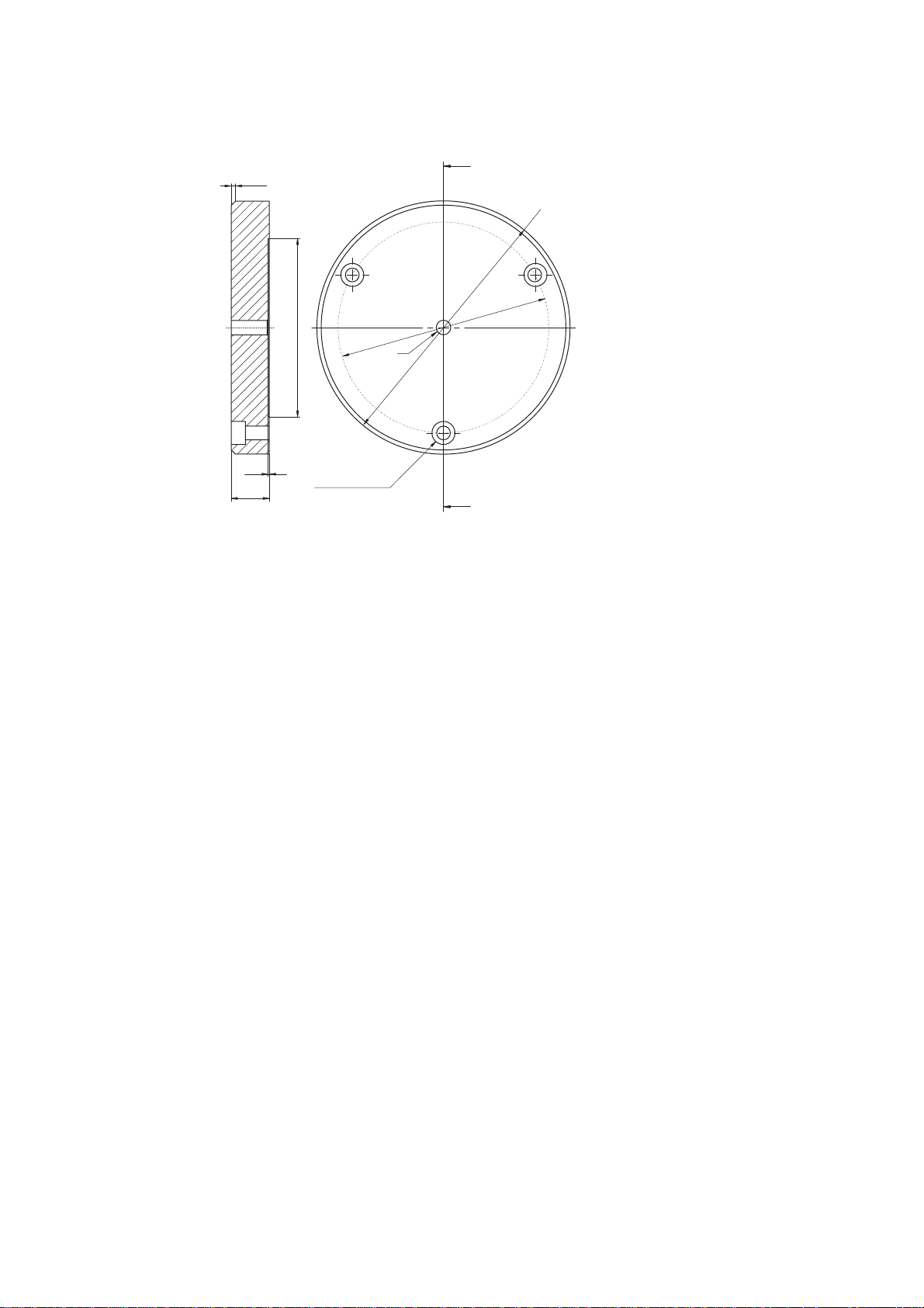
B Optional Accessories for the Sensor Head OFV-511/-512
2 x 4 5 °
ø 8 5
M 8
A
0
2
1
ø
0
0
1
ø
0 . 5 0
1 8
A - A
C o u n t e r s i n k i n g D I N 7 4
K m 6 ( 3 x )
A
Figure B.5: Base plate for t he f lexible arm OF V-039 (dimensions not specified are given in
mm)
B-6

C Basics of the Me as urem ent Pro cedur e
I
I
L
----
f
v
---
f
v
-- -
Appendix C: Basics of the Measurement Procedure
C.1 Theory of Interferometric Velocity and Displacement M easurement
Optical interf eren ce c an be o bs erved wh en two co he rent lig ht b ea ms ar e
made to coincide. T he resulti ng intensit y e.g. on a photo dete ctor var ies with
the phase difference ∆ϕ between th e t wo b eams ac cor ding t o th e equ ation
max
∆ϕ()
--------2
1 ∆ϕcos+()⋅=
Equation C.1
The phase difference
∆ϕ
is a functio n of the pat h di fference ∆L between the
two beams accord ing to
∆
where
∆ϕ 2π
λ
is the laser wavel ength .
---
⋅=
λ
Equation C.2
If one of the two beams is scatte red back f rom a mo ving obje ct (the obje ct
beam), the path difference be come s a function of time ∆L=∆L(t). The
interference fring e pattern moves on the detector and the disp la cement of the
object can be determined using directionally sensitive counting of the passing
fringe pattern.
On scattering fr om the ob ject the object bea m is s ubjecte d to a sm all
frequency shift which is called Dopple r shift fD and is a function of the velocity
component in th e direct ion of the object be am acco rding to
--
2
D
⋅=
λ
Equation C.3
Superimposing ob ject b ea m a nd int ernal re fe ren ce beam i .e. two
electromagnetic waves with s lightly different fre quencie s generat es a beat
frequency at t he de tect or which is eq ual to the Do pp ler shift. T he r atio C.3 to
determine the v eloc ity is, howe ver, independent of its s ign. T he di rect ion of
the velocity can be det ermi ned by int roducin g an addit ional fixe d frequen cy
shift f
correct sign. Th us the resu lting fre quency at the det ector f
in the interferom eter to which t he Doppler shift is added wi th the
B
is given by
mod
mod
fB2
⋅+=
λ
Equation C.4
Interferometers of this type which are di rectio nally se nsitive are describ ed as
heterodyne.
C-1
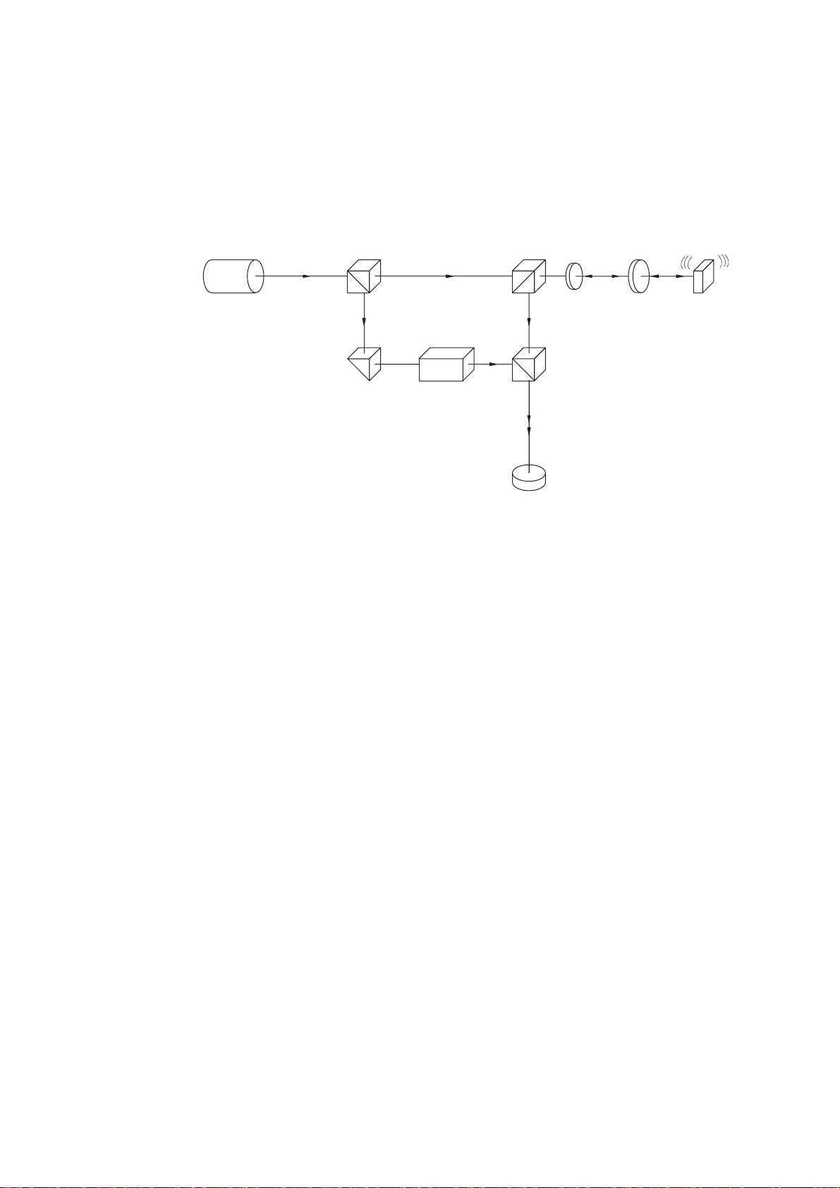
C Basics of the Me asur emen t Pro cedur e
C.2 Optical Configuration in the Sensor Head OFV-303/- 353
In Polytec’s vibrometers, th e veloc ity and disp lacem ent mea sureme nt is
carried out using a m odifie d Mach- Zehnde r interfer omete r. The optical
configuration in the sen sor hea d OFV-303/ -353 is sho wn sche matical ly in
figure C.1.
B S 1
O b j e c t B e a m
R e f e r e n c e
B e a m
B r a g g C e l l
P r i s m
Figure C.1: Optical configura tion of t he i nter fero meter in t he sen sor h ead OFV -303/-3 53
B S 2L a s e r
l / 4
B S 3
D e t e c t o r
L e n s
O b j e c t
The light source is a heli um neon l aser which provide s a linear polarized
beam. The po lari zing bea m spl itter BS 1 splits t he b eam i nto th e obj e ct b eam
and the refere nce bea m.
The object beam passes through the polarizing beam splitter BS2 as well as a
λ
/4 plate, is then f ocu sed by the le ns on the o bjec t and sca tter ed ba ck fr om
there. The p olari zin g beam s plitt er BS 2 th en fun ctio ns as a n op tica l
directional coupl er toget her with the λ/4 plate, and defl ects the object beam
to the beam s plitt er B S3. A s bo th arm s of th e "i nter na l" i nter fero m eter a re
symmetrical, th e optical path differe nce betwe en the obje ct beam and the
reference bea m vanis hes withi n the interf erome ter. The resulting path
difference is equal to twic e the distanc e between t he beam sp litter BS2 and
the object.
C-2
The Bragg cell in the reference arm of the interferometer generates the
additional frequ ency offset to det ermine t he sign of the ve locity.
The resulting inte rferenc e signal of the obje ct beam and refere nce bea m is
converted into an e lect rica l sign al in the p hoto de te ctor and su bsequ en tly
decoded in the contro ller.

C Basics of the Me as urem ent Pro cedur e
C.3 Optical Configuration in the Sensor Head OFV-511/-512
In Polytec’s vibromete rs, the ve locity and displa cemen t measur ement is
carried out usin g a modifie d Mach- Zehnd er inter ferom eter.
OFV-511
The optical configuration in the sensor he ad OFV-511 is shown schematically
in figure C.2.
B S 1
O b j e c t B e a m
R e f e r e n c e
B e a m
P r i s m
Figure C.2: Optical configuratio n of the inte rfer ometer in the sensor head OFV- 511
B r a g g C e l l
B S 2L a s e r
B S 3
D e t e c t o r
C o u p l e r
F i b e r
l / 4
The light source is a he lium neon lase r whic h provides a line ar polar ized
beam. The p olar izing bea m s pl itter B S1 sp lits t he b eam i nto th e ob je ct b eam
and the refere nce bea m.
F i b e r H e a d
o r
M i n i S e n s o r
O b j e c t
The object beam passes th rough the polar izing be am spli tter BS2 and is
focused into the fiber with an input coupler. The beam is then emitted from the
λ
end of the fi ber, passes through a
/4 plate and is focu sed usin g the fibe r
head or the mini sens or on th e object an d scat tere d back from there. The
polarizing bea m splitt er BS2 th en functi ons as an optica l direct ional co upler
together w ith th e λ/4 plate, a nd de fl ects t he ob jec t be am to t he b eam s pl itter
BS3. As both arms of the "internal" interferometer are symmetrical, the optical
path difference vani sh es wi thin the i nter fero met er. The resultin g path
difference is equal to twice th e distance bet ween the be am split ter BS2 and
the object.
The Bragg cell in th e re fe rence ar m gen er ates t he addit iona l fre que ncy offse t
to determine the sign of the velocit y.
The resulting inte rferen ce signal of the object beam a nd refer ence beam is
converted in to an el ectr ical sig nal in t he p hoto de tect or a nd s ubseq uen tly
decoded in the contro ller.
C-3

C Basics of the Me asur emen t Pro cedur e
OFV-512
R e f e r e n c e B e a m
F i b e r H e a d
M i n i S e n s o r
B S 4
C o u p l e r
F i b e r
o r
The optical configuration of the sensor head OFV-512 is shown schematically
in figure C.3.
B S 1 O b j e c t 1
O b j e c t B e a m
B r a g g C e l l
l / 4
B S 2L a s e r
B S 3
D e t e c t o r
C o u p l e r
F i b e r
l / 4
F i b e r H e a d
o r
M i n i S e n s o r
O b j e c t 2
Figure C.3: Optical configuration of the interferometer in the sensor head OFV-512
In contrast to the OFV- 511, the beam is coupled out of the referen ce arm as
well as the object arm here. As t he resu lting sign al only de pends on the path
difference, this allows o pt ical g ene ra tion o f a true d ifference s ignal . W it h the
OFV-512 the prism in the refer ence arm is replaced by anoth er bea m splitt er
BS4 which has the sam e c harac teri stic s as t he beam sp litte r BS 2. Th e sig nal
measured her e is thus the re lative veloc ity or dis place ment betwee n the two
objects.
C-4

D Functional Description of the Controller
Appendix D: Functional Description of the Controller
D.1 Overview
The main function of the controller is to demodulate the radio frequency signal
(RF signal) pr ovid ed by th e inte rfer omet er i n the s ens or he ad . The f reque ncy
of the signal is the ca rrie r of the vel ocity inform ation and the phase i s the
carrier of the displ aceme nt infor mation. Secon dary func tions suc h as hum an
interfacing, dis play and filters improve the user friendliness of the vibrometer.
An overview of the functional structure of the controller is shown in figure D.1.
P C - b a s e d
D i s p l a c e m e n t D e c o d e r
A m p l i f i e r
S e n s o r
I n p u t
B r a g g C e l l
D r i v e O u t
S i g n a l L e v e l
O u t p u t
L e v e l
D e t e c t o r
S i g n a l
C o n d i t i o n i n g
S i g n a l
L e v e l
D i s p l a y
j
m o d
O s c i l l a t o r
f
L O
f
B
f
D
m o d
D e m o d u l a t o r I
f
D
m o d
D e m o d u l a t o r I I
D i s p l a c e m e n t
( o p t i o n a l )
j
f
D
V
f
D
V
Figure D.1: Block diagram of the controller OFV-3001
The RF signal from the sen sor head (s ensor input) ini tially passes the
functional block signal co nditioni ng where it is pre-proc essed to optimal ly
drive the following bloc ks. Subse quent ly the signa l path is split up into t he
branches velocity signa l decodin g (below) and displ acemen t signal decoding
(above). If t he c ont roller is f ully e qu ip ped t h ere a re two v eloci ty dec od ers
installed (demodul ator I an d demodu lator II ).
D e c o d e r
r e f
C o n t r o l B u s
D i s p l a c e m e n t
O u t p u t
I E E E - 4 8 8
S y s t e m C o n t r o l
R S - 2 3 2
V
m o d
S w i t c h
V
m o d
L o w P a s s
F r o n t P a n e l
A m p l i f i e r
D i s p
V e lo
V e l o c i t y
O u t p u t
The velocity is mod ulate d on th e radio fr equency of the input signal. In the
velocity decode r, an AC voltage is generated whic h is proporti onal to t he
instantaneous velocity of the ob ject with t he aid of so-ca lled FM
demodulators. In the disp lacem ent decod er, optionally the phase of the RF
signal is dem odul ated . In d oi ng s o, an AC vo ltage is ge nerat ed w hich is
proportional to the i nstantaneou s positi on of the ob ject.
The individual demodulators require different reference frequencies which are
in a fixed relation ship to th e driv er freque ncy of the Bragg ce ll in the
interferometer. They are generated in the centra l oscillat or block,
synchronized wi th the dri ver signa l f or t he Brag g cell.
D-1

D Functional Description of the Controller
The velocity decoder is followed by a low pass filte r which supp resses
spurious RF c ompo ne nts and lim its th e ban dwidth of the o utpu t sign al t o
reduce backgroun d nois e. Via the syste m contr ol, variou s cutoff fr equenci es
can be set for the low pass filter.
The last block in each sign al path is an am plifier w hich scales the output
signals and can optima lly drive su bsequ ent sign al proces sing units.
The system contr ol manage s the com muni cation of the cont roller w ith the
environment via the front panel and PC interfaces and also the internal setting
of all parameters for the individual functional blocks.
Not included in the block diagram is the power supply unit which generates all
supply voltages f or t he s ens or h ea d and t he c on trol ler.
D.2 Signal Conditioning
The RF signal from the se nsor hea d first of all has to be pre-pr ocess ed to
optimally drive the various demodulators. The signal conditioning includes the
following func tions:
Measurement
of the input
signal level
Stabilization
of the signal
amplitude
Limitation of
the bandwidth
•
Measurement of the inpu t sign al level
•
Stabilization of the signal amplitude
•
Limitation of the bandwidth
•
Drop-out reduction via the tracking filter
•
Down-mixing of the f requency
The measurement of t he input signal level is required t o provide the user with
information of the back sca tterin g prope rties of the objec t and as a help to
optimally fo cus the laser beam . The le vel is con verte d to a log arith mic ally
scaled DC voltage. This signa l is visual ized on the sensor hea d and on the
controller as a bar disp lay and is availabl e at the BNC jack SIGNAL fo r
external usag e.
Stabilization of the signal amplitude is neces sary for t he followi ng signal
processing steps as the input signal level can fluctuate by several orders of
magnitude due to th e extrem ely different back scat tering proper ties of the
objects.
Limitation of the ban dwidth at t he inp ut of th e sign al pr oce ssin g elec tr onic s is
required beca use, for low vel ocit ies, o nl y a nar row sec tion o f the syst em
bandwidth is occup ie d by t he FM s ig nal. I n th e re main ing band wi dth onl y
noise is recorded . For th is reas on, at th e inpu t sectio n of the co ntrol ler, a
switchable filter is installed which limits the noise bandwidth depending on the
velocity meas uremen t rang e set. A s this is ca rrie d out righ t at th e input,
however, the bandwidth limitation also affects the displace m ent decoding and
under certain circumstanc es has t o be taken into consider ation (r efer als o to
section 4.2.3, Optimizing the RF bandwidth).
D-2

D Functional Description of the Controller
Drop-out
reduction via
the tracking
filter
Drop-out reduct ion via th e tracki ng filter plays a ve ry impo rtant role in optica l
signal processing . The ligh t scat tered bac k from the object has a spe ckled
nature i.e. at any in stant the detec tor sees a l ight or a da rk spec kle. The low
signal amplitude of the dark speckle can lead to loss of signal, so-called dropouts. When decod ing the vel ocity, this interrupti on of the in put si gnal cau ses
short but high noise signals, so-called spikes which make it very difficult to
analyze the output si gnal. These drop- outs are effectively reduced by a socalled tracking fi lter inte grat ed in the in put se ction of the contr oller. This is
done by an electron ic circu it to reg enera te hig h frequen cy sig nals base d on
the principle of the pha se loc ked loop (P LL).
The princi ple o f si gn al rege nera ti on by th e trac k ing fi l ter i s ba s ed on repla c ing
the input signal with a dist orted amp litude by a stable signal from a voltage
controlled oscilla tor whic h is synchron ized with the frequ ency an d the phase
of the input signal. Suitable circuit design can make it possible to maintain the
synchronized co ndition app roxim ately, even if the input signal is tem porari ly
lost. The mechani cal analog f or this des ign is a flywh eel which may lose a
small portio n of its e ne rgy if t he d rivi ng f or ce i s brie fly in ter rupte d bu t
continues to run at almost the same number of revolutions per minute and can
drive a subsequent mechanism without disruption. It is easy to see that this
effect gets better, the higher the inertia of th e wheel is. At the sa me time the
flywheel however lo ses the a bility to follow rapi d chang es in the re volutions
per minute i.e. the dyna mic res ponse of the drive sy stem gets wor se. The
same correlatio n also appli es to the el ectroni c tracking filter w hich thus
always represents a com promise betwee n the reg enera tion effect and the
dynamic tracking behavior of the input signal. Basically, good drop-out
elimination or noi se supp re ssion is alwa ys inv olv ed w ith lim ite d dynam ic
response. If the ma xim um ac ce lera tion is ex cee de d, th e s ync hron iz atio n
between the input signal and the oscillator is lost (the tracking filter loses lock)
which leads to drasti c signal dis tortions at the sig nal outpu t. Pract ical adv ice
for setting the tracking filter can be found in section 4.2.2 and sectio n 4.2.3.
The internal s truc ture o f th e trac king f ilter c ircui t is sh own in figure D.2. The
function of the vol tage controll ed oscillat or (VCO ) has alre ady bee n
mentioned. The con trol signa l which syn chroni zes the osc illator is gen erated
in the phase detector which monitors the phas e difference bet ween the i nput
signal and the oscil lator sign al. The dyn amic ch aracter istics of the
configuration are mai nly dete rmine d by the inter nal low pass filter. The
maximum accele rati on which the tracki ng fil ter can st ill follow dep en ds on th e
filter bandwidth. The low pass tim e constant is switched between SLOW and
FAST via the system control and thus ad apts the dyna mic charac terist ics to
the application. The trackin g filter can be turn ed off via a bypass if the
acceleration s are too hi gh or in the ca se of good optical signals.
A m p l i f i e r
I n p u t
C o n t r o l B u s
Figure D.2: Block diagram of t he tracking filt er circuit
P h a s e
d e t e c t o r
L o w p a s s
f i l t e r
o f f
V C O
V
f
o n
O u t p u t
D-3

D Functional Description of the Controller
Down-mixing
of the
frequency
Down-mixing of the frequenc y in the in put section is requir ed to conve rt the
carrier freque ncy of the FM si gnal fr om 40M Hz orig inally to lower
intermediate freq ue ncies . W ith t he se i nte rm edia te fre qu enc ies, the v eloc ity
decoder can work opt imally i n the indi vidual me asurem ent ra nges. Down mixing is carried out by a mixing process which does not affect the modulation
content of the F M s igna l. T he va riab le f requ en cy fLO is produced by the so-
called local osc illator i n a fixed re lation ship t o the driv e freq uency o f the
Bragg cell.
D.3 Oscillator Section
The oscillator secti on gene rates al l drive freq uenci es for ope rating the other
subassemblies in t he vib rom eter. The drive freq uen cy f or the B ragg ce ll is o f
central importanc e as it di re ctly dete rm ine s t he op tic al fr eq uency o ffset in th e
interferometer an d thus the center frequen cy of th e carrier si gnal. The phase
reference signa l
relationship to the carr ier freq uency fB.
The variable mixing fre quency fLO is automatically set by the system control
dependent on the sel ected ve locity meas uremen t range.
ϕ
for the displacem ent dec oder is gen erated with a fixe d
ref
D-4

D.4 Velocity Decoder
mm
s
-
V
mm
s
-
V
mm
s
-
V
mm
s
-
V
mm
s
-
V
mm
s
-
V
mm
s
-
V
mm
s
-
V
D.4.1 The Various Velocity Decoders
Tech nicall y it is just ab out impo ssibl e to attain al l desira ble and rea lizabl e
characterist ics of the velocity decoder in a single univ ersal subassembly. The
modular concept of the controller thus permits the use of two different velocity
decoders which can be installed sim ultaneously. The selection of the
decoders depends on the ap plication. The model s availabl e are the OVD- 01
and OVD-02 which feature t he followin g character istics.
D Functional Description of the Controller
OVD-01
OVD-02
The OVD-01 is a velocity decode r for applic ations in the acou stic frequ ency
range up to approxi mately 20kHz. In this ran ge, it has e xcelle nt lineari ty and
accuracy ch aract eri stic s. W ith f ive me asu re men t ra ng es from 1 t o
1,000 it covers the full dynam ic rang e of the vibro meter w ith high
-------- -
-------- -
resolution. Th e upper fou r measu rement range s can be us ed up to
frequencies of 50k Hz and hi gher wh ile retaining the ir good ch aracter istics,
however amplitude ac curacy an d linearity de creas e with higher frequen cies.
The measureme nt ran ges 125 a nd 1 ,000 c an be use d from the
-------- -
-------- -
frequency 0Hz (full DC ca pability).
The OVD-02 as a broad ban d decoder is suitable univer sally fo r almost al l
applications in the frequency range up to 1.5MHz. Four measurement ranges
from 5 to 1,000 cover mos t tech nical appli cation s with su fficient
-------- -
-------- -
amplitude res olut ion. Char ac teri sti c is the e xce llent a mplit ude and p hase
frequency res ponse wi th e xtre m ely good a m plitu de flatne ss up to th e hi ghe st
frequencies. I n the mea sur eme nt ran ge s 125 and 1 ,0 00 t he
-------- -
-------- -
OVD-02 can detect DC ve locity com ponents. This is useful e.g. when
measuring on rotating discs. When setting up the sensor head, large DC
components which mi ght other wise o verlo ad t he m e asure men t ra nge can
then be mini mized.
D-5

D Functional Description of the Controller
D.4.2 Operating Principle
The velocity decoder determines the essential measurement properties of the
vibrometer. Velocity deco ding is in pri ncipal an FM d emodulat ion proc ess
which converts the ve loc ity de pen de nt Do pp ler freq uen cy o f the
interferometer si gnal into an AC voltage . The lineari ty and ban dwidth of the
demodulator determine the accuracy of the vibrometer. In contrast to FM radio
which works with the s ame m odu lati on pro ced ure, con si derab ly h ig her
frequency deviation s occur in t he vibrome ter which m ake signi ficantly hi gher
demands on t he d emo dul ator s:
FM radio: max. freq uency deviati on 75kH z,
Vibrometer: max. frequency deviation 32M Hz,
In the OFV-3001 controller, different respectively optim ally ad apted
modulators are s w itc hed o n i n the in dividua l ve loci ty m e asure m ent ra nge s. A
maximum of two velocity decoders can be installed which in measurement
ranges which are in part the same, satisfy differing requirements with regards
to the maximum frequenc y or linea rity. The decoders and measu rem ent
ranges are se lect ed via the s ystem control and the in tern al b us . At the s ame
time, the corresp ondi ng setti ngs on the su basse mblie s oscillat or and sig nal
conditioning are ca rried ou t intern ally.
max. modulatio n freq uency 53k Hz (ste reo)
max. modulation frequency 1.5MHz
D.4.3 Low Pass Filter
The signal generate d by the FM de mod ulator alwa ys contains spurious RF
components and its noise bandw idth corr esponds with the m aximum
frequency of the respective measurement range. A subsequent low pass filter
suppresses the RF co mponen ts and limits the noise ba ndwidth acco rding to
its cutoff frequency. This makes a rough adaptation of the m easurem ent
bandwidth to the applic ation pos sible and m akes the si gnal eva luatio n in the
time domain significantly easier due to the improved signal-to-noise ratio. The
filters are adjusted via the system control.
In the OFV-3001 controller low pass filters with 3 rd order Be ssel
characteristics ar e used. Bess el filters ha ve the ad vantage of a line ar phase
response and th us optim al tran smiss ion beh avior fo r puls es. Besse l filte rs
were selected, as the signal proce ssing bef ore the low pass al so show s a
linear phase respon se and th us this ad vantage is re tained eve n when the
filter is switched on. Due to the char acteristi cs of the Bess el filter, however
signal amplitudes are attenuated even at relative low frequencies. This has to
be taken into conside ration f or accura te me asurem ents. The filter
characteristics as we ll as rules of thumb f or using them are prov ided in
section 4.2.2.
D-6

D.5 Displacement Decoder
D.5.1 Mode of Opera tion
The phase of the interf erome ter signal is the carr ier of th e displa cement
information. To be directiona lly sens itive, Polyt ec’s vibrome ters work on the
heterodyne prin ciple i.e . the ph ase is mod ulated onto a ca rrier si gnal. The
information requi red thus rides o n the phase difference be tween the drive r
signal for the Bragg cell and th e mod ulated sign al at the ph oto dete ctor. A
displacement of the object by ±λ/2 produces a full de modul ation perio d (a
fringe passage) at th e photo det ector.
The number of fringes co unte d is thus a m easure of the displ aceme nt of the
object with an accuracy and resolution of λ/2 which is 316.4nm for the helium
neon laser. The mode of operation in whi ch merel y the num ber of frin ges is
counted is calle d the di rect coun ting mode. I t corresp onds wi th the
measurement range 80µm/V.
As the interferomet ric phas e chang es contin uously with the di splacem ent of
the object, displacements of less than λ/2 can also be resolved with the aid of
electronic int erpo la tion tec hn iq ues. Th is i s re al ized in t he m ea sure ment
ranges below 80µm/V in which resolutions down to 2nm can be attained. The
specified resolu tion cor responds to one incr ement (count pul se) whic h is
accumulated d irect iona lly s ens itive by a 1 2bit counter in the disp lace m ent
decoders OVD-10 and OVD-20.
D Functional Description of the Controller
For certain applicati ons, in part icular for low fre quenc y vibratio ns, th e
limitation of the measu rement range to 1.3m m in the dir ect count ing mod e
due to the 12bit co unting ra nge may not be sufficient . The disp lacem ent
decoder has there fore be en equ ippe d wit h thr ee adj us table ran ge ext en sion s
which cover a displacement measurement range up to 82 mm (±41mm
amplitude). The me asurem ent rang e is exten ded by di gitally dividing the
number of counts by in tege rs. This pr ocedur e of course decrea ses th e
resolution, ho wever th e a cc ura cy is re tained.
D.5.2 The Various Displacement Decoders
OVD-10
OVD-20
OVD-30
In the following sec tions th e digital ph ase modu lation of the standar d
displacement decod ers OVD-10 and OV D-20 will be des cribed.
The displacement decoder OVD-30 is suitable for ultrasonic measurements at
frequencies down to 20MHz and operates with analog phase demodulation. It
is described in a separate m anual.
VibSoft FC
The PC-based d ispl acem en t de coder VibSoft FC ext en ds t he coun ting r ange
of the internal disp lace men t decod er s OVD-10 an d OVD-20 to 32bit and thus
offers a significant exten sion of the m easur eme nt range. The co unter conte nt
is handled directly as a nume rical valu e thus i ncreasi ng the me asurem ent
accuracy. The PC-based displacement de coder is also descr ibed in a
separate manual.
OVD-40
The model OVD-40 ha s been desi gned ex clusively for opera tion w ith the
external PC-b ased disp lace ment dec oder VibSo ft FC. It provide s the sa me
resolution as th e OVD-20, bu t does not gene rate a n analog di splace ment
signal.
D-7

D Functional Description of the Controller
D.5.3 Operating Principle
The functional str ucture of th e displac ement decode r is show n schema tically
in figure D.3.
O s c i l l a t o r
j
r e f
n x
j
m o d
P h a s e
M u l t i p l i e r
j
m o d
Q u a d r a t u r e
D e m o d u l a t o r
D I R E C T I O N
C O U N T
C o u n t e r
1 2 b i t
D / A C o n v e r t e r
D
A
L o w P a s s
D i s p l a c e m e n t
S i g n a l
C o n t r o l B u s
Figure D.3: Block diagram of the d isplacement decod er
The subassembly phase mu ltiplier is only incl uded in th e high reso lution
models OVD-20 and OVD-40. In the displacement decoder OVD-10, the
modulated signal
ϕ
is processed direc tly in th e fu ncti ona l blo ck quad rat ure
mod
demodulator. Here the displacement inform ation is digitally reco nstruct ed
from the phase difference betwee n the re fere nce signa l
modulated signal
ϕ
. As a result, the pulses COUNT and DIRECTION are
mod
generated. Each COU NT pulse cor resp onds to one period of the
interferomete r signal i. e. a displ acemen t of the obj ect by λ/2. The binary
value of the signal DIRECTION provides the sign. Both pulses are counted by
the binary forward-r eve rse cou nt er, the status of which thus corres pon ds with
the instantaneous pos ition of the o bject . T he cou nt ing ra ng e is of 12bit which
corresponds to 4, 096 incre ments. As ea ch inc rement is equiv alent to
316.4nm, total displa cemen ts of up to approxi mately 1. 28m m (±0.64 mm
amplitude) can be measured in the so-called direct counting mode with a
resolution of 31 6.4nm. To make use of th e full countin g rang e, the counte r is
reset as appropri ate with an exte rnal CLEAR pu lse at eac h zero cros sing of
the object (refer to sec tion 4.2.3 , CLEAR f unction ).
To be able to present the displacement signal in real-time with an oscilloscope
e.g., the coun te r co nt ent is c on ver ted by a 12bit digital-to-an alo g c onv erte r
into an analog voltage with a step resolution of approximately 4mV. The steps
are smoothed with a low pass fil ter at high fr equenci es. A subse quent
amplifier stage sca les th e signal ac cord ing to the measu remen t rang e set.
C L E A R
ϕ
and the
ref
D-8
In the high resoluti on displ acemen t deco ders OVD-2 0 and OV D-40, th e
additional functional block phase multiplier realizes an even higher resolution.
In this subassembl y, the interferometer signal
ϕ
is pre-processed in th e
mod
sense of an interpolation before the quadrature demodulator converts it into a
pulse train with a hig her resol ution. This gene rates int eger mu ltiples of the
phase deviation ∆ϕ and thus increase s the re solution of the disp laceme nt
decoder by the sa me fact or. This means that in th e lowes t measu remen t
range (0.5µm/V) an increme nt of appr oximate ly 2nm i s attained. As th e
counting rang e i s always 12bit, the to tal m easurement range is decreased by
the respective mu ltiplier. In the lowest range th us displ acemen ts up to
approximately 8µm (±4µm amplitude) can be measured. Bear in mind

D.5.4 Accur acy
D Functional Description of the Controller
however, that due to the phase multiplicati on both th e origina l band width of
the modulated signa l and th e pulse frequ ency at the cou nter are increase d.
The technical limi ts in the direc t counti ng mode are reac hed at a vel ocity of
10m/s, ho wever in the high resolut ion rang es this value decreases
approximately by the multiplier (refer also to section 4.2.3, Measuremen t
range).
Due to its workin g princi ple, the d isplac emen t deco der at tains its h ighe st
accuracy in the di rect coun ting mode. As long as t he optica l signal is free of
drop-outs, exactly on e COUNT pulse is generated and accu mulated for each
phase cycle of the interferometer. The accuracy of the equivalent increment of
316.4nm is sol ely determ ined by th e wavel ength stabi lity of the helium ne on
laser which is in the or der of ma gnitud e of 10-5. Helium neon lasers are a
generally reco gniz ed st an dard for l ength meas ureme nt s. Ap a rt fr om the digi ta l
residual error, the status of the digital fringe co unter thus very ac curate ly
corresponds wit h the i nstantaneo us po siti on o f the ob ject, indep end en t of t he
influence from elec tron ic comp onents. The sa me ap plies fo r the ex tended
measurement ranges where only every nth COUNT pulse is accumulated.
Due to tolerances and drift of the analog components however, the
subsequent digital-to-analog conversion and amplification cause an additional
static calibratio n er ror of max im um ±1% of the measure men t v alue. At hi ghe r
frequencies, the amplitude frequency response of the smoothing filter causes
an additional fr equency depend ent er ror of ±0.5%.
In the high reso luti on ran ge s, t he int erpol a tion (pha se mu lti plic atio n) i s an
additional poten tial sourc e of error. As with every interpo lation, ad dition al
linearity errors can occur between the known values, which depend on the
frequency and a cce lera tion o f t he o bject . Up to a ch arac te rist ic f requ enc y for
every measurement range, this dynamic amplitude error can practically be
ignored as it remai ns below 1% . Abo ve this fr equency which i s to be taken
from the decoder sp ecific ations, the amp litude error can in crease up to
approximately 10 %. A p re cise erro r diag ra m c an n ot b e prese nt ed i n a cl ea r
way due to the depende ncy on acce lerati on.
D-9

D Functional Description of the Controller
D-10

E Interface Operation RS-232 and IEEE-488 /GPIB
Appendix E: Interface Operation RS-232 and IEEE-488/GPIB
E.1 Configuration of the Interfaces
Using the interfac es RS-23 2 and IEEE- 488/GPIB the follow ing com mands
are supported:
•
query and change the se tting s of the control ler
•
query the over rang e
•
query the optical signal level
•
focus the laser beam only for vibrometers with the sensor head OFV-303
The interfaces ca n be confi gured via the display of the cont roller in the menu
CONFIG ( re fe r to section 5.9.3).
RS-232
IEEE-488/
GPIB
The two following configurations are possible:
•
9,600Baud, 8 data bits, 1 stop bit, no parity bit ( factor y settin g)
•
4,800Baud, 8 data bits, 1 stop bit, no parity bit
For the interface IEEE-488/GPIB, every address in the range from 0 up to
and including 30 can be set.
The factory settin g is: Addr ess = 5
The interface has the fo llowi ng f un ctions wh ich co mpl y wi th t he s tanda rd
IEC-488.1:
SH1, AH1, T4, L 2, TE 0, L E0, SR0 , RL1 , PP 0, DC 1, DT 0, C0
E.2 Interface Co mmands
E.2.1 Control Commands RS-232
REM
Queries the opera tion mo de:
Answer Answer with ECHOON
0 = LOCAL REM0
1 = REMOTE REM1
2 = LLO REM2
GTL
REN
LLO
Sets the status LOCAL (REM=0).
Sets the status REMOTE (REM=1).
Sets the status LLO (LOCAL LOCK OUT) (R EM=2).
E-1

E Interface Operation RS-232 and IEEE-488/GPIB
mm
s
-
V
RENDCL
DCL
Sets the status REMOTE and load s the fo llowin g initializ ation sett ings:
TRACK = 1 (OFF)
VELO = 4
FILT = 1 (OFF)
AMPL = 7 (5,120
(1,000 )
-------- -
µ
m/V)
Loads the initialization settings (see above) without changing the current REM
status i.e. the respective s tatus LOCAL, REM OTE or LLO is m aintained .
IFC
Loads the initializa tion set tings an d sets the status LO CAL. The comma nd
corresponds to DCL+GTL.
E.2.2 Control Commands IEEE-488/GPIB
The controller reco gniz es three di fferent ope rating modes fo r rem ote contr ol
via the interface IEEE-488/GPIB:
LOCAL
The vibrometer is c ontrolle d via the di splay an d the keys on the fr ont of th e
controller.
REMOTE
The vibrometer can be controlled via the front panel and via the interface. The
status REMOTE is set when an IEEE -488/GPIB bus contro ller ass erts the
signal REN and addre sses th e control ler.
LLO
= LOCAL LOCK OUT. The status LLO can only be set from the status
REMOTE. In this mod e, it is only poss ible to op erate vi a the inte rface
IEEE-488/GPIB. Key inp ut on t he fron t panel is ignored , only the k ey RESE T
retains its function.
The operating mode of the controller is shown on the front panel with the LEDs
REMOTE and LLO as follows :
Operating mode
LOCAL Off Off
REMOTE On Off
LLO On On
E.2.3 Echo Commands
ECHOON
As default, the echo f unctio n is swit ched off when th e syst em is bei ng
controlled r emo te ly. With this c omm and an e ch o is r etur ned for vali d
commands.
ECHOOFF
The echo function is switch ed off. An answer is on ly retur ned on the
corresponding com man ds .
L
ED
REMOTE LLO
E-2

E.2.4 Measurement Range Setting and Query
mm
s
-
V
mm
s
-
V
mm
s
-
V
mm
s
-
V
All transmissions from and to the co ntroller are termi nated with t he ASCII
character LF (L ine Feed) i. e. decima l 10, hexad ecima l 0x0a. In the exam ples
given here, this chara cter is des cribed with th e escape sequen ce "\n"
according to its presen tation in the pr ogramm ing langu age C.
Invalid settings are ignored.
Velocity Decoder
E Interface Operation RS-232 and IEEE-488 /GPIB
Command Description Answer
VELO? Queries the measurement range
set
Range number
(ASCII character )
1...9
(refer to table below)
VELO1...
VELO9
Sets the corresponding
measurement range (refer to
- VELO1...
table below)
VELO Loads the initialization setting for
- VELO
the measurement range
(refer to command RENDCL)
OVR Queries whether the full scale
range has been exceeded
0 = no overrange
1 = over range
(Overrange)
Measurement range Range number
-------- -
OVD-01 OVD-02
15516
25 2 7
125 3 8
1,000 4 9
Answer with
ECHOON
VELO1...
VELO9
VELO9
OVR0
OVR1
Examples:
VELO2\n
VELO7\n
VELO?\n
If an OVD-01 is installed, the meas ureme nt range i s set to
-------- -
25 .
If an OVD-02 is installed, this veloci ty decod er is sele cted and
the measureme nt range i s set to 25 .
-------- -
As an answ er, a string with the numbe r of the vel ocity
measurement ran ge set i s retu rned.
If the measur eme nt rang e 25 o f the OVD -02 is sel ected ,
-------- -
the controller ret urns the st ring "7\ n".
E-3

E Interface Operation RS-232 and IEEE-488/GPIB
Displacement Decod er
Command Description Answer
AMPL? Queries the set measurement
range
AMPL1...
AMPL7
AMPL Loads the initialization settings
RES Triggers the reset function of the
Measurement range Range number
Sets the corresponding
measurement range (refer to
table below)
for the measurement range
(refer to command RENDCL)
displacement decoder
µ
m/V OVD-10 OVD-20
0.5 - 0
2-1
8-2
20 3 3
80 4 4
320 5 5
1,280 6 6
5,120 7 7
Range number
(ASCII character)
1...7
(refer to table below)
- AMPL1...
-AMPL
-RES
Answer with
ECHOON
AMPL1...
AMPL7
AMPL7
Examples:
AMPL2\n
AMPL7\n
AMPL?\n
If an OVD-20 is installe d, t he me asur emen t rang e is s et t o
8µm/V.
The measurem en t ra ng e is s et t o 5,12 0µm/V.
A s an answ er, a string with the num ber of the displace men t
measurement range set i s returne d.
If the meas urem ent r ange 32 0µm/V is sele cted, th e cont roller
returns the string "5\n".
E-4

E.2.5 Filter Setting and Query
Tracking Filter
E Interface Operation RS-232 and IEEE-488 /GPIB
Command Description Answer
TRACK? Queries the setting of the tracking
filter
1 = OFF
3 = SLOW
4 = FAST
TRACK1
TRACK3
Sets the tracking filter to this
value
TRACK4
TRACK Loads the initialization setting for
the tracking filter
(refer to command RENDCL)
Low Pass Filt er
Command Description Answer
FILT? Queries the setting of the l ow
pass filter
FILT1...
FILT4
Sets the low pass filter to this
value
FILT Loads the initialization setting for
the low pass filter
(refer to command RENDCL)
1 = OFF
2 = 100kHz
3 = 20kHz
4 = 5kHz
Answer with
ECHOON
TRACK1
TRACK3
TRACK4
- TRACK1
TRACK3
TRACK4
-TRACK
Answer with
ECHOON
FILT1...FILT4
- FILT1...FILT4
-FILT
E-5

E Interface Operation RS-232 and IEEE-488/GPIB
E.2.6 Signal Level Query and Motor Control Commands
Signal Level
Command Description Answer
LEV Queries the optical signal level 0 = no level
Answer w ith
ECHOON
LEV0...LEV40
1 = level 1
2 = level 1 and 2
3 = level 1 to 3
...
40 = level 1 to 40
Motor Control Comma nds
Command Description Answer
l Slowly drive the motor to the left until
-l
the command N is received
L Quickly drive the motor to the left until
-L
the command N is received
r Slowly drive the motor to the right until
-r
the command N is received
R Quickly drive the motor to the right until
-R
the command N is received
N Stops the motor - N
LIM Queries the status of the motor while it
is in motion
R = reache d right l imit
L = reached left limit
N = not yet reached limit
Answer with
ECHOON
E-6
 Loading...