

Page 1

TABLE OF CONTENTS
SECTION PAGE
1. GENERAL DESCRIPTION……………………………………………………………….. 1
2. CONTROL SPECIFICATIONS, TABLE I ………………………………………………..3
3. INSPECTION …………………………………………………………………………..….3
4. INSTALLATION ………………………………………………………………………..…3
4.1 Mounting of Open Chassis OC2-500 Control ……………………………………3
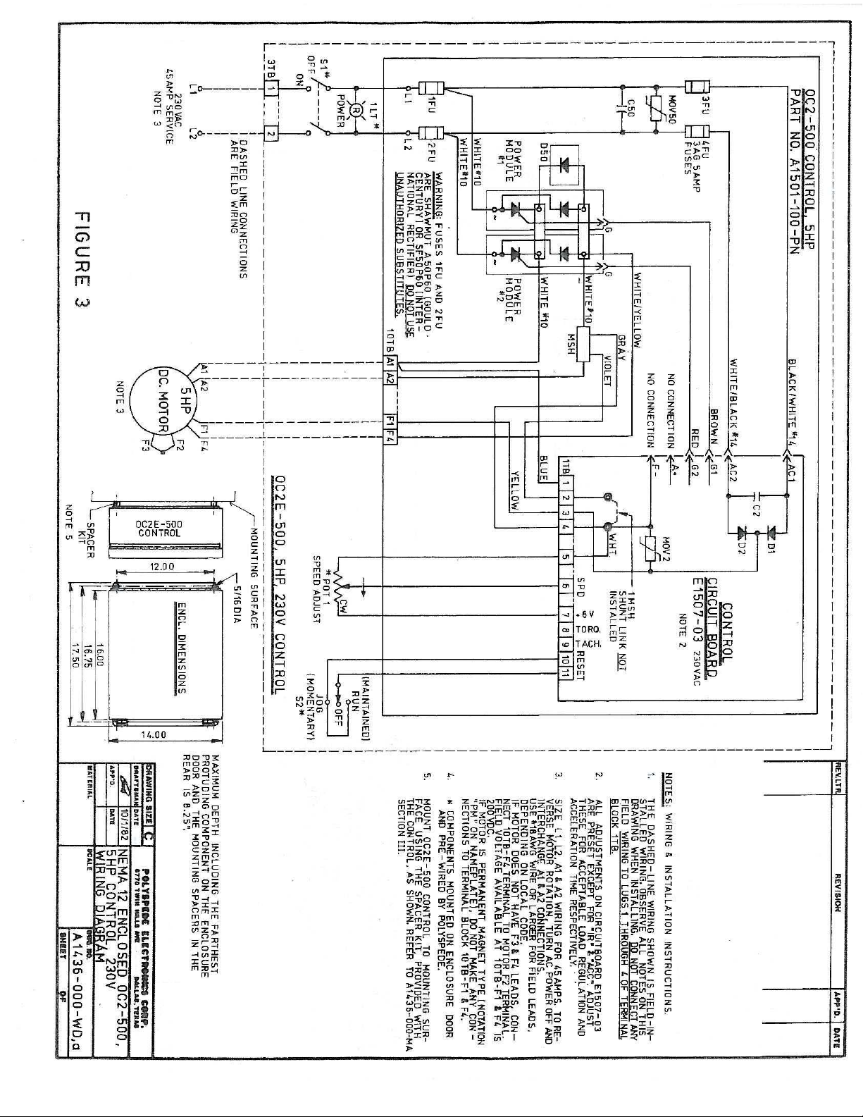
4.2 Mounting of Enclosed OC2E-500 Control ……………………………………….4
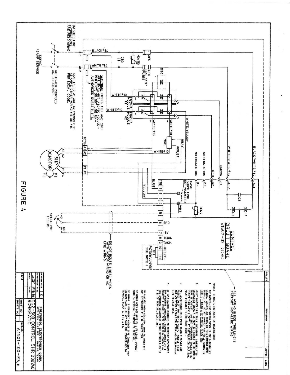
4.3 Wiring Procedure …………………………………………………………………4
5. INITIAL TURN-ON PROCEDURE ……………………………………………………….6
6. ADJUSTMENTS …………………………………………………………………………...6
6.1 Adjustment Procedure Chart, Table II …………………………………………….8
7. CONTROL OPERATION ………………………………………………………………….10
8. TROUBLESHOOTING …………...………………………………………………………..10
8.1 Troubleshooting, Table .…………………………………………………………...10
Troubleshooting Table II …...……………………………………………………...11
8.2 Troubleshooting Procedure – In Case of Fuse Blowing …………………………...13
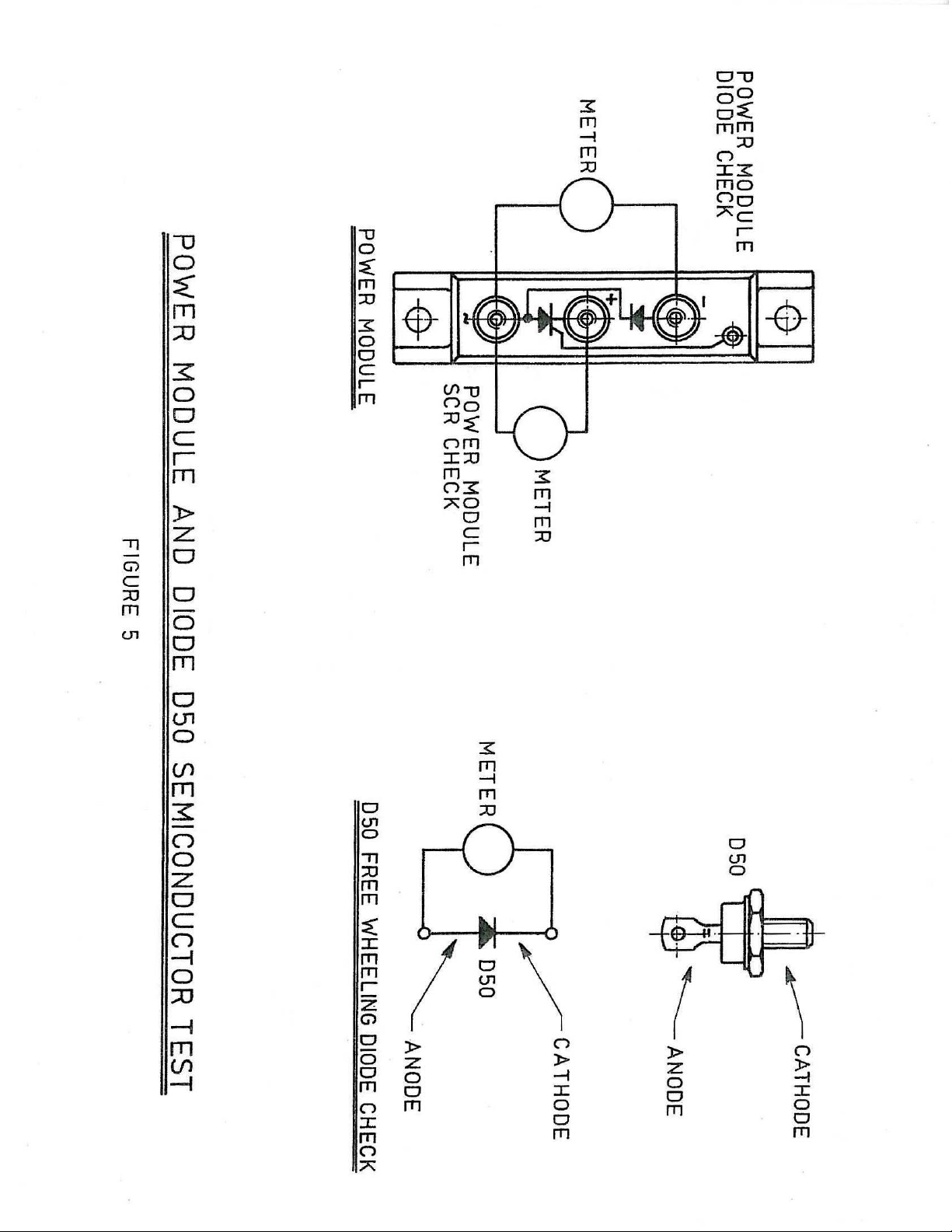
9. POWER MODULES AND D50 TESTING ………………………………………………...15
10. MOTOR TESTS …………………………………………………………………………….16
11. CONTACTOR OPERATED SYSTEMS (OPEN CHASSIS CONTROLS ONLY) ……….16
11.1 Contactor Operation on the DC Lines ……………………………………………..16
11.2 Contactor Operation on the AC Lines ……...……………………………………...17
11.3 Contactor Reversing ……………………………………………………………….17
12. DYNAMIC BRAKING (OPEN CHASSIS CONTROLS ONLY) …………………………18
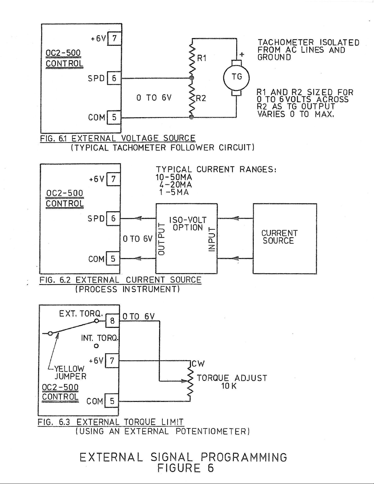
13. EXTERNAL SIGNAL PROGRAMMING ( OPEN CHASSIS CONTOLS ONLY) ………18
13.1 Speed Programming ………………………………………………………………..18
13.2 Torque Programming ………………………………………………………………19
14. TACHOMETER FEEDBACK ………………………………………………………………19
Table IV …………………………………………………………………………….20
15. MAINTENANCE – CONTROL ……………………………………………………………..21
16. MAINTENANCE – MOTOR ………………………………………………………………..21
17. MAINTENACE – SPEED REDUCER ………………………………………………………21
Page 2

Page 3

1. GENERAL DESCRIPTION
When ordered, the OC2-500 open chassis control can be supplied in a NEMA 12
enclosure. When supplied in this manner, the basic OC2-500 control is furnished
with the following additional features, and is designated by model number OC2E500:
a) Power “Off-On” switch with separate pilot light indication.
b) “Run-Off-Jog” (momentary position ) mode selection switch.
c) Speed Adjust Potentiometer.
The OC2-500 open chassis motor control has been designed as a basic building
block solid state regulated power unit. The OC2 open chassis, unit, which uses
state of the art control circuitry, can be used by itself, by wiring in the provided
speed potentiometer, as a straight forward speed regulated control, or can be
incorporated into much more sophisticated system designs utilizing contactor
operation, external speed programming, tach feedback, etc. (These applications
and others are discussed later in this manual.
The control circuitry incorporates a sophisticated regulator scheme that maintains
motor speed precisely at the set level within the advertised motor and control
speed rages. There are two control loops, speed and torque, that operate
simultaneously and independently of each other. In most cases the speed loop is in
control. (The speed loop can use either armature voltage or tachometer voltage
feedback. ) When in control, the speed loop maintains speed constant at the
desired value until the motor load (torque) requirements exceed a preset value,
normally 150% of rated motor torque. As this occurs, the torque regulator
assumes control of the SCR’s and allows speed to drop as is necessary in order to
maintain and not exceed the preset limit value. If the motor load continues to
increase, as would the case if a driven machine had jammed, the torque limit is
capable of holding this preset value of torque precisely without run out down to a
locked rotor or zero speed condition. Operation in both the speed and torque
modes is smooth and stable, and through the use of optimized networks transfer
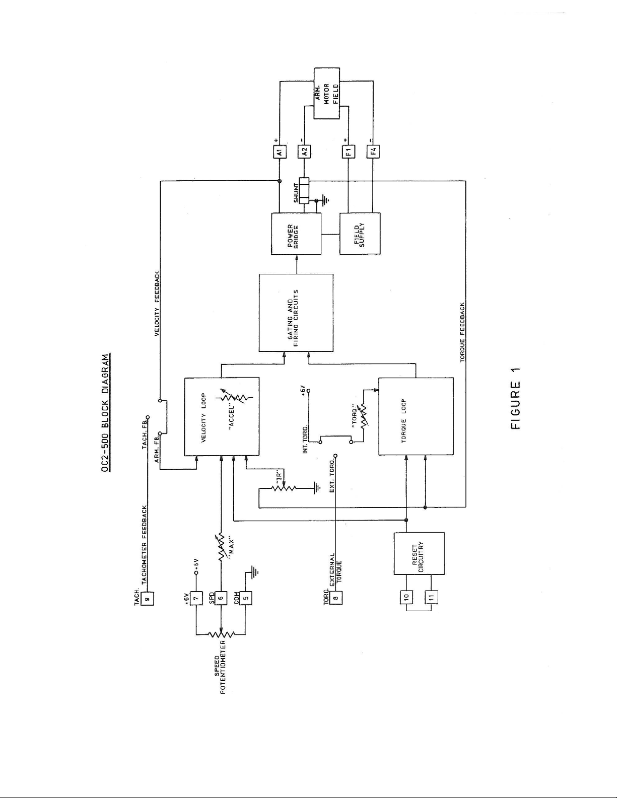
between the two loops is smooth and bump less. Figure I is a block diagram of the
OC2-500 control system.
In the speed mode the control hold the motor speed constant at a valued
determined by the voltage present at the speed input. In a basic control this
voltage is set by a Speed Adjust potentiometer. In most controls armature voltage
is used as feedback in the speed (velocity) loop. When using armature
1
Page 4

Voltage feedback, load changes are compensated for by an “IR” compensation
circuit which senses any increase in armature current and raises the armature
voltage to compensate for the increased voltage drop in the motor armature. This
circuit thus controls the regulation (speed changes) due to load changes. The
motor current is continuously monitored by a very low resistance current shunt.
The signal from this shunt, which is also used in the torque loop, is then fed to the
“IR”circuit, which permits the achievement of no load to full load regulation of
less than 1% of base speed. In applications requiring load regulation better than
1% of base speed, tachometer feedback must be used.
The OC2 unit is protected against excessive current overloads by the
outstanding OC2 torque (current) limit circuitry. In addition, the OC2 unit
is protected against damage due to accidental wiring shorts or grounds by
fast-acting rectifier-protection type fuses inserted in the AC input lines.
********************************************************
WARNING
IF FUSE REPLACEMENT BECOMES
NECESSARY, USE ONLY THE SPECIFIED
FUSES. THE USE OF SUBSTITUTE FUSES
MAY VOID CONTROL WARRANTY
*******************************************************
2
Page 5

2. CONTROL SPECIFICATIONS
TABLE I
Horsepower 5
Model Numbers OC2-500 (OPEN CHASSIS)
OC2E-500 (ENCLOSED)
Normal RMS Input Current 43 Amps RMS
Rated Motor Current 24 Amps DC
Input Voltage (Single Phase) 230VAC +/- 20 Volts
Fuses (1FU & 2FU) A50P60 (Shawmut) or
SF5060 ( IR )
(3FU & 4FU) 3AG, 5 Amp
Input Frequency 50 / 60 Hz
Output Voltage to Armature ( Rectified
and Unfiltered ) 0 – 180VDC
Output Voltage to Field (Rectified and Unfiltered) 200VDC
Speed Range 0 – 100%
Load Regulation for 100% Load Change
a) With Armature Feedback Adjustable to +/- 1% of base
speed
b) With Tachometer Feedback +/- 0.1 of base speed typical
Speed range for Specified Regulation 20:1
Speed Dial Characteristics Linear
Linear Acceleration Time 0.5 to 15 Seconds adjustable
Torque Limit (% of Rated Motor Current ) Approx. 75 to 150% adjustable
Maximum Ambient Temperature 40°C
External Signal Capability See Section 13
3. INSPECTION
Check for shipping damages. If damage is found, report it to the carrier
immediately. Do not attempt to operate the drive if visible damage exists to the
circuit board or other components.
4. INSTALLATION
4.1 MOUNTING OF OPEN CHASSIS OC2-500 CONTROL
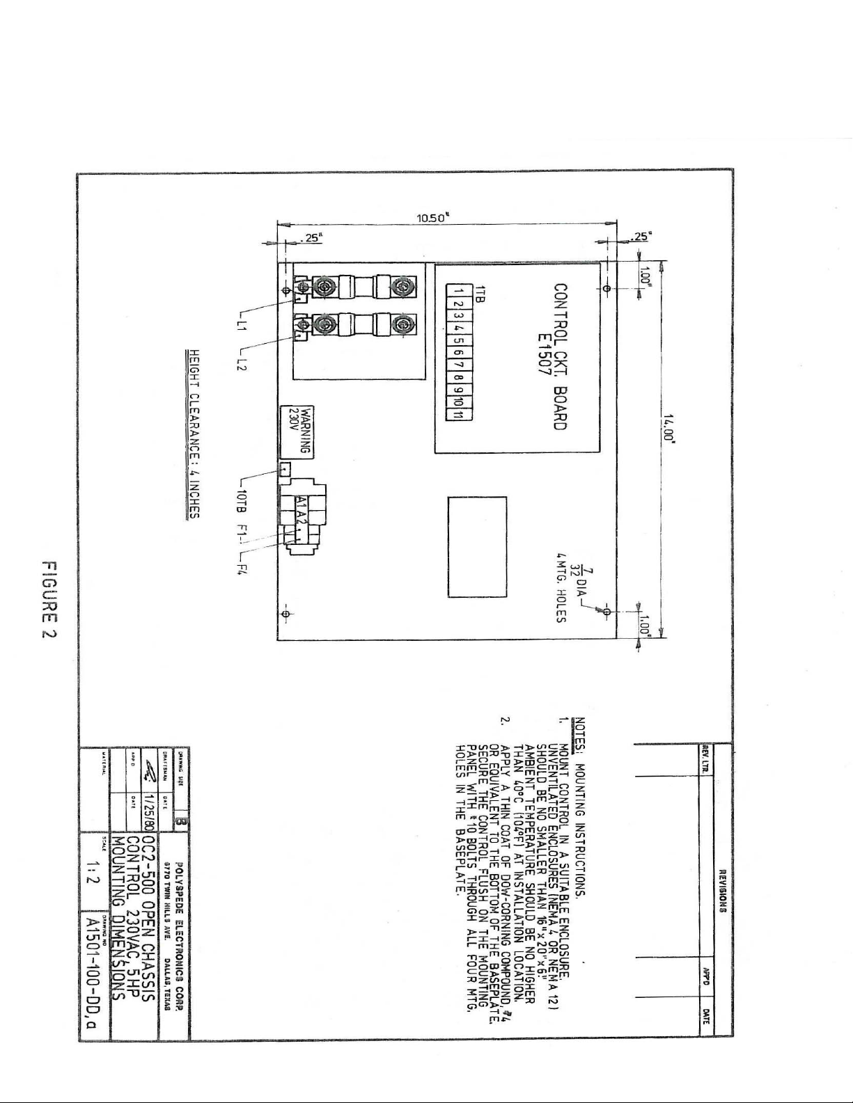
Four holes are provided in the base plate for mounting purposes. There is no
preferred mounting position for the OC2-500 control. Four holes for mounting the
OC2-500 should be drilled in the enclosure wall or sub-panel per the mounting
dimension shown in A1501-100-DD (Figure 2).
Apply an even, thin coat of Dow Corning Compound #4 or equivalent to the
3
Page 6

bottom side of the base plate on the OC2-500 control to facilitate heat transfer.
When mounting in the enclosure, select an area that will minimize the possibility
of metal parts falling between the PC board and OC2-500 base plate, or on the PC
board and thereby causing shorts. Since the enclosure wall or sub-panel is actually
used by the OC2-500 as a heat sink, it is necessary that the panel be of sufficient
size to furnish adequate cooling. If a single OC2-500 is placed in an unventilated
enclosure with no other heat-generating equipment, a 20”x20” enclosure of
minimum clearance depth is of adequate size. The top edge of the OC2-500 base
plate must be located at least 4” below the top surface of the enclosure. If these
conditions are met, no fans need to be used.
If other equipment which generates significant heat is installed in the cabinet with
the OC2-500, however, increase enclosure size or add a circulating fan to
distribute heat within the enclosure. In all cases, though, it can be determined if a
larger enclosure and/or fan will be needed by measuring the power cube base
plate temperature. The power cube base plate temperature under all conditions
cannot exceed 100°C.
4.2 MOUNTING OF ENCLOSED OC2E-500 CONTROL
The enclosed OC2E-500 control must be mounted in an environment that does not
exceed 40°C. Since this control uses the back of the box for cooling, the control
must be mounted in a location to permit airflow over the back of the enclosure. It
is mandatory that the OC2E-500 enclosure back be spaced at least one-half inch
from any air restricting or thermally non-conductive walls. Spacers are provided
with the control to permit proper mounting. Refer to Figure 3.
4.3 WIRING PROCEDURE
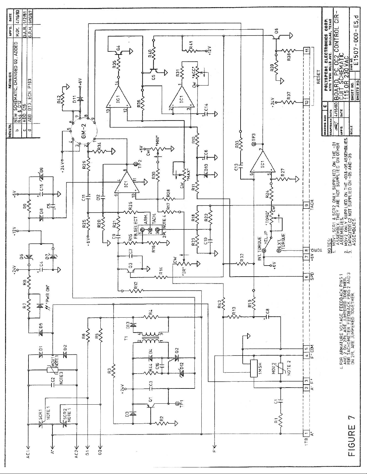
Use drawing A1501-100-ES ( Figure 4) on open chassis controls and A1436-000WD (figure 3) on enclosed controls for proper external wiring connections. The
rated RMS current for 5 horsepower control is given in these wiring diagrams. All
wires which carry armature current are sized the same as those carrying AC line
current. (This is necessary to account for the form factor of the current being
supplied to the armature of the motor.) All other wire connections may be # 18
AWG.
On enclosed controls the AC input connections are made to 3TB. On open chassis
controls the input connections are made directly to the double fuse holder. For
open chassis controls, wire connections to terminal strip 1TB on the printed
circuit board are not to be lugged.
4
Page 7
Strip ½” insulation from the ends of the wires to be connected to 1TB, and insert
wires under the wire clamps of the terminals. It is not recommended that wires
smaller than #18 AWG be used to make connections to the terminal strip 1TB.
Since smaller wires may not be adequately held by the wire clamping plates on
the terminals. After wiring, make sure that there are no short to the chassis or
shorts between terminals.
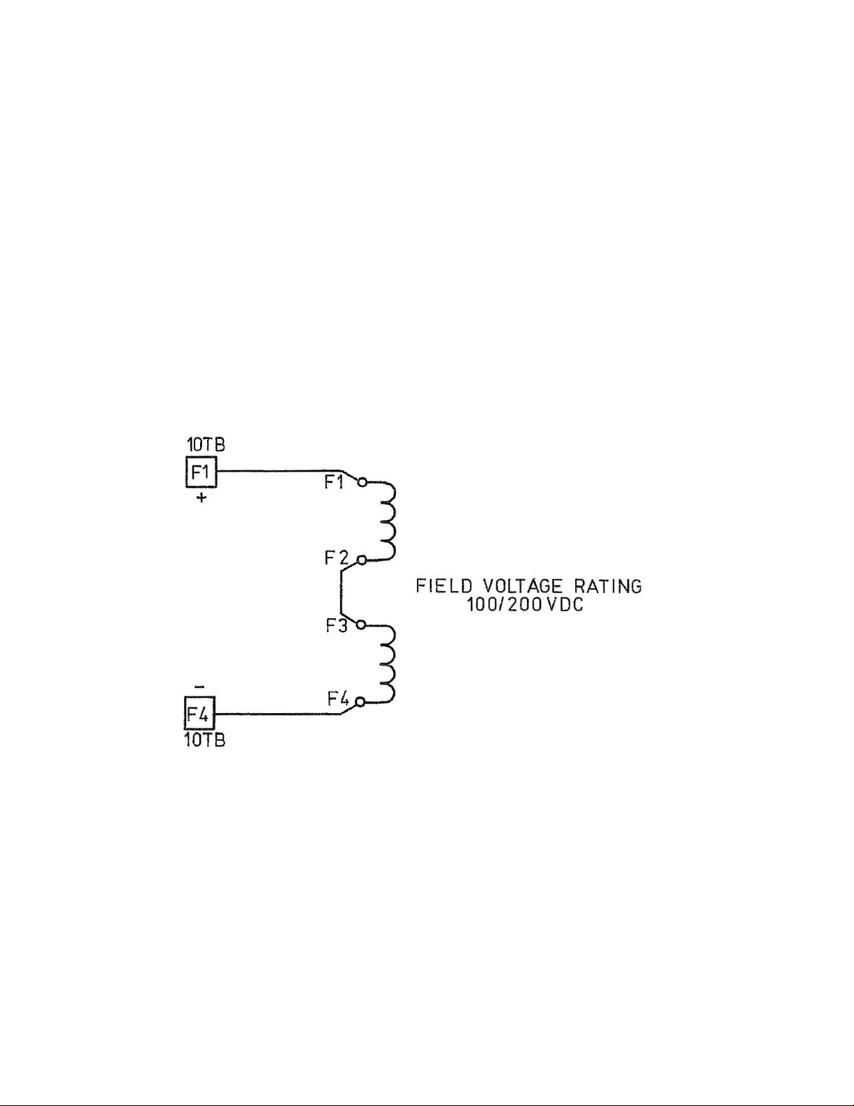
Caution should be observed when connecting the motor shunt field. Some DC
motors are provided with dual field windings, which are connectable for high or
low voltage.
The field voltage supplied on the OC2-500 control is 200 VDC. A typical dual
voltage field winding connection is shown below:
Refer to the wiring information plate found on the motor, and connect field
windings for the proper voltage of the OC2-500. Some motors have permanent
magnet fields. In this case no connections are made to terminals F1 and F4 on
10TB
5
Page 8

5. INITIAL TURN-ON PROCEDURE
Recheck all wiring. Accidental grounds on any of the motor leads or speed
potentiometer wires may damage the unit when power is applied. Make sure
that the AC service is of the correct voltage, as indicated by the voltage
warning label located on the control.
Before applying power, check to make sure the feedback select jumper on
2PL is in the “Arm” position, pins 1 and 2 on 2PL jumpered together, for
controls using armature voltage feedback. On controls that will use
tachometer feedback, refer to the Tachometer Feedback Section 14 in this
manual.
Turn the speed potentiometer to zero. Apply power from the AC disconnect
switch (S1 on enclosed controls). An LED located on the PC board will light
indicating power is applied. ( In contactor operated systems, also energize
the DC contactor.) Slowly advance the speed potentiometer while observing
the motor. If motor rotation is incorrect, turn power off at the AC disconnect
and reverse the A1 and A2 connections to terminals A1 and A2 on 10TB of
the OC2-500 control. If the motor runs at maximum seed with the
potentiometer fully counterclockwise, and slows down as the potentiometer
is rotated clockwise, the potentiometer is wired in backward. With power
off, reverse the outer leads of the speed potentiometer.
The control should be checked for satisfactory operation throughout the
entire speed range. If instability is observed, maximum speed is higher than
normal, or if acceleration time is not as desired, adjust the control as
described in the following section. If initial operation is satisfactory, no
readjustments are necessary.
6. ADJUSTMENTS
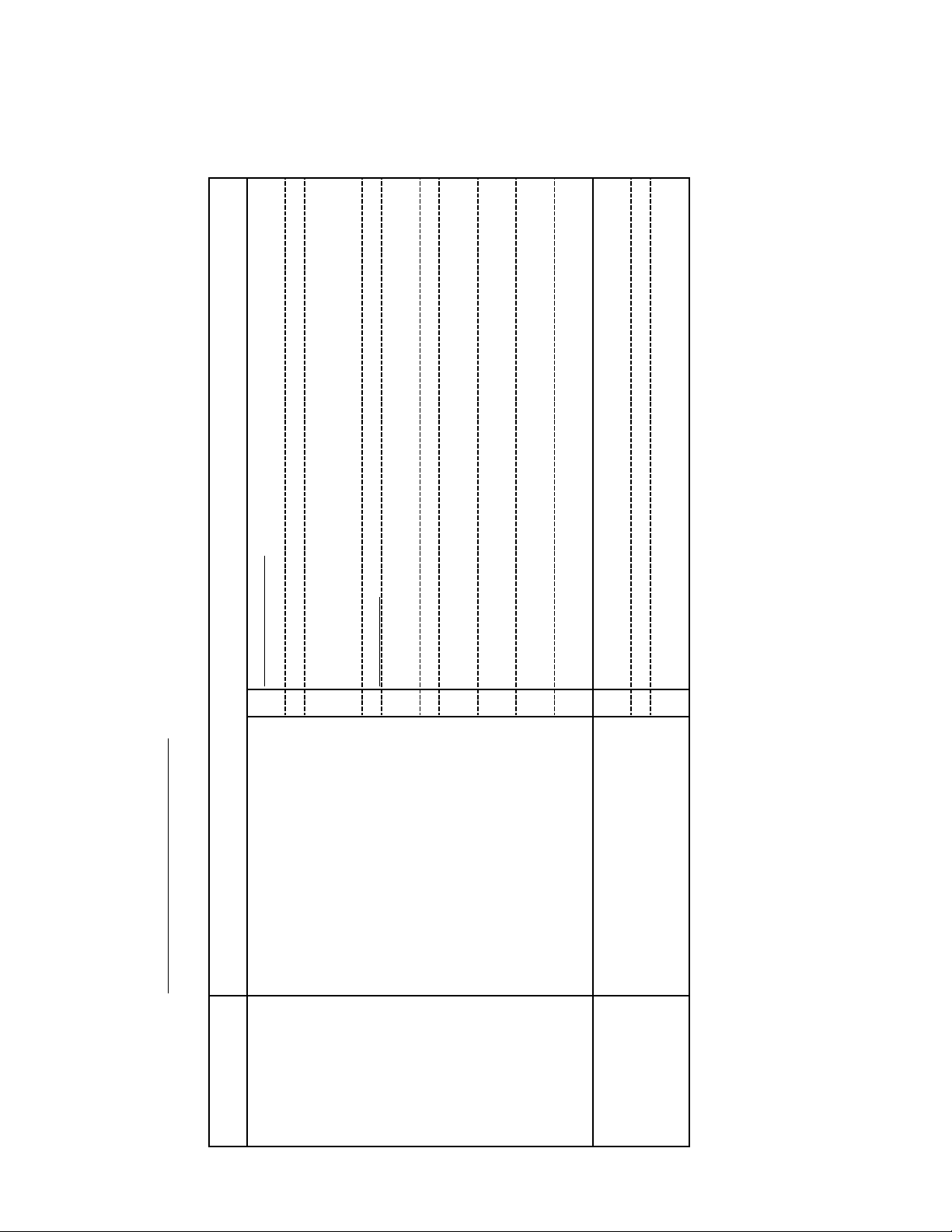
Five internal adjustments are provided.
a) Minimum speed (“MIN”)
b) Maximum speed (“MAX”)
c) IR (load) compensation (“IR”)
d) Torque Limit (“TORQ”)
e) Acceleration (“ACC”)
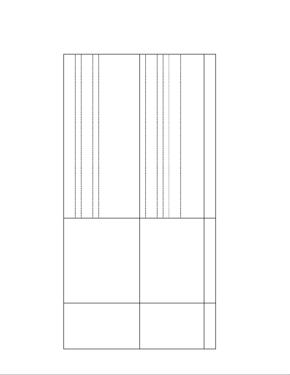
The function of these adjustments is described in Table II.
All adjustments, except “IR”, are preset at the factory. A ‘typical’ test motor
is utilized. The “MAX” and “TORQ” adjustments do not depend on
individual motor characteristics and therefore should be correct as received.
The “IR” and “MIN” adjustments, however, are somewhat dependent on
6
Page 9

Characteristics of the particular motor used, and should there fore be made
by the user when the drive is installed. Jobsite adjustment of “IR” is
necessary to achieve specified regulation. The adjustments are permanent;
periodic readjustment is not necessary. (The IR adjustment is set fully
counter clockwise when using tachometer feedback.)
Perform adjustments per Table II and in the order listed in Table II. The
adjustments are completely independent of each other except as noted
below:
a) “IR” has a slight effect on
“MIN”, but “MIN” does not
effect “IR”
b) “MIN” has a slight effect on
“MAX”
Performing adjustments in the order listed in Table II thus eliminates any
necessity for repeating a calibration operation.
Note that torque limit (“TORQ”) is independent of the other adjustments.
Since this is basically a protective adjustment, preset at the factory, it should
not be readjusted except to decrease the limit point.
7
Page 10
N
ADJUSTEMENT PROCEDURE:
pp
b
b
p
b
p
g
p
(
)
(
)
p
q
g
p
gg
g
b
p
TABLE II
-on meter.
eed decrease is noted.
ht or tachometer.
until little or no s
d
eed with strobe li
oximate method:
Back off "IR" trim pot 1/3rd of the span between this setting and zero setting.
A
) Rotate "IR" trim pot clockwise until motor begins to hunt.
This method usually results in slight over compensation.
c)
etween motor and control. Do not use clam
Exact method:
Turn drive power off and connect a DC ammeter in series with the A1 motor lead
) Set speed control knob for 20% speed.
a)
If motor speed decreased as motor was loaded, adjust the "IR" trim pot and
Load the motor shaft until ammeter reads rated motor current [see nameplate].
Read motor s
e)
c)
to occur.
and
c
ue limitin
eat
re
In performing ( d ) and ( e ), be sure motor is not loaded heavily enough to cause
tor
Remove ammeter and reconnect A1 motor lead. Recheck control at very low
f)
.
in
eed for co
s
g)
) Rotate the "MIN" trim pot clockwise until motor starts to rotate.
c) Decrease the "MIN" trim pot setting until rotation stops.
DESCRIPTION OF FUNCTION: NOTES
6.1 ADJUSTMENT PROCEDURE CHART
ADJUTMENT
Sets the load regulation (% slowdown of
motor as shaft load is changed from zero to
If load slow down is of no concern, rotate
AME
"IR" a) Set speed control knob for 20% speed.
[In tach feedback systems this pot must be
"IR" trim pot fully counterclockwise.
turned fully counterclockwise.]
eed.
Sets the zero calibration of the speed
control knob.
Clockwise rotation of "MIN" trim pot
increases s
"MIN" a) Set the speed control knob to zero.
Page 11
)
p
b)
p
)
y
)
p
p
y
)
p
b
)
p
)
p
p
(
g
g)
.
g
p
)
g)
g
p
)
clockwise.
eed control knob full
ower off.
Turn drive
a
be read.
ma
ower on. Turn s
lated
Connect a DC voltmeter between A1 and A2 motor leads at the motor.
Turn
d
c) Set meter scale so that rated armature voltage ( 180 volts as noted on motor name
e) Adjust "MAX" trim pot until meter reads name plate rated voltage ( 180 volts)
NOTE: If desired, a tachometer or strobe light may be used in lieu of the DC
voltmeter. Proceed as described above, except adjust the "MAX" trim pot until
tachometer or strobe light indicates that motor is turning at base speed.
ower off.
ower on.
etween motor and control unit.
Turn drive
a
Turn
b) Connect a DC ammeter (NOT a clamp-on type) in series with the A1 motor lead
c
current.
., 10% settin
e.
eed
eed control knob for a low s
Watch ammeter to assure that control is limitin
Set s
d
e) Apply friction braking to the motor shaft until until motor stalls out. CAUTION:
ot counter clockwise to decrease.
h, rotate the "TORQ"
.
late
Adjust to desired acceleration time. Clockwise rotation increases time.
If current is to hi
name
f) Stall current should read roughtly 150% of rated armature current ( see motor
a
Calibrates the speed at which motor turns
when speed control knob is fully clockwise.
Clockwise rotation of the "MAX" trim pot
increases maximum motor speed.
"MAX"
TORQUE LIMIT Sets the maximum
"TORQ"
Accerleration adjustment sets time for
torque that can be obtained from the motor,
and the maximum armature current that the
control unit will deliver. Torque adjustment
is preset at the factory usually for 150% of
rated motor torque ( current). Clockwise
rotation of the "TORQ" trim pot increases
the torque that the motor will deliver.
motor to reach set speed.
"ACC"
Page 12

7. CONTROL OPERATION
Prior to shipment, all OC2-500 and OC2E-500 controls are tested and
completely adjusted at the Polyspede factory. Therefore, after properly
wiring and following the “Initial Turn-On Procedure” section, the control
should be functioning properly. If the motor speed cannot be controlled,
fuses blow, or other problems are experienced with the control, refer to the
Troubleshooting Chart, the Troubleshooting in Case of Fuse Blowing
Section, and/or the Motor Test Section.
8. TROUBLESHOOTING
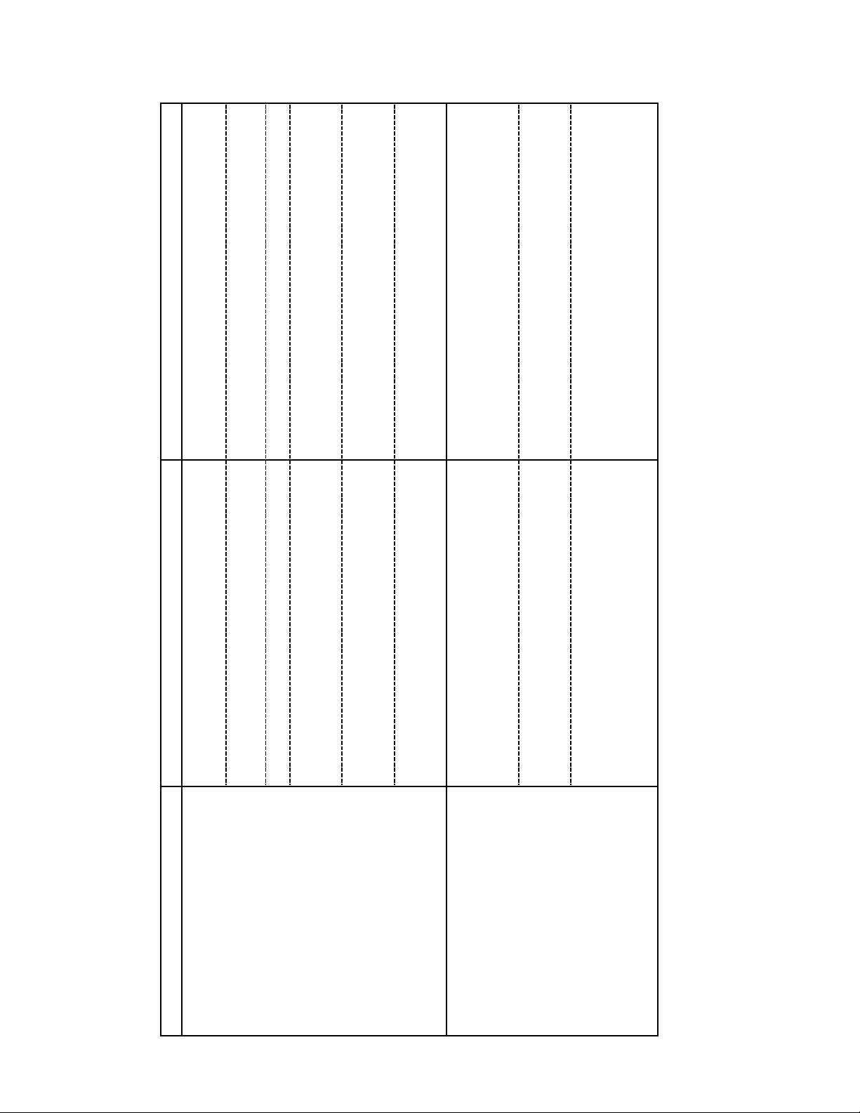
8.1 TROUBLESHOOTING TABLE
The majority of major malfunctions which are normally encountered,
can be summarized as stated below:
a) Motor does not run.
b) Motor runs only at full speed or over speed.
c) System blows fuses or breakers repeatedly.
Table III tabulates these malfunctions, probable causes, and actions required
for testing. If fuse blowing is the problem, read Table III and then follow the
checkout procedure of Section 8.2
*************************************************************
DANGEROUS VOLTAGES ARE PRESENT ON THE
CONTROL CIRCUIT BOARD AND TERMINALS.
ONLY PERSONNEL FAMILIAR WITH ELECTRICAL TEST
PROCEDURES, TEST EQUIPMENT, AND SAFETY
PRECAUTIONS SHOULD ATTEMPT THESE TESTS
WARNING
10
Page 13

PAGE INTENTIONALLY LEFT BLANK
10a
Page 14
I
ACTION
]
p
p
y
j
p
g
)
stems section
erated s
Check AC Line voltage.
TABLE II
POSSIBLE CAUSE
TROUBLESHOOTING
will not light.
a) AC input to control missing. "PWR ON" LED also
b) Fuse blown ( "PWR ON" LED aslo will not light). Remove, check, and if necessary replace fuse(s).
Check field voltage between terminasl F1 and F4 on 10TB.
Should read 200 VDC.
Check motor field wiring. Check resistance as given in motor
tests with the power off.
torque under heavy loads. [Does not appy to PM
c) Motor Jammed mechanically. Check by rotating the shaft manually.
d) Field voltage low or missing, causing insufficient
under heavy load. [Does not apply to PM motors.]
motors.
e) Motor field open or disconnected and operating
ermit control operation. See the external wiring diagrams and
contactor o
Check motor field wiring. Check resistance of the field as
given in the motor tests with the power off
under light load. [Does not apply to PM motors.]
f) Terminals 10 and 11 on 1TB not connected. Either a permanent jumper or contact closure must be used to
a) Motor field open or disconnected and operating
Check field voltage. Field voltage should be 200 VDC.
under light load. [Does not apply to PM motors.]
b) Motor field voltage low or missing and operating
Refer to the tach feedback section for Proper board set-up.
ether..
ered to
tach and motor combination, or mini jumper is
c) Tach feedback: Control board improperly set up for
um
missing between pins 2 and 3 on FB SELECT plug
2PL. (For armature feedback pins 1 and 2 are
MALFUNCTION
Motor does not run or will not run to
top speed.
a)
Motor runs only at full speed. (In tach
feedback systems, proper maximum
voltage cannot be adjusted.)
b)
Page 15
Speed potentiometer resistorance should measure 1K.
With potentiometer wired voltage between terminal 6(+)
and 5 should vary zero to 6 VDC.
warning label.
Recheck all motor connections as given on:
A1501-100-ES (open chassis)
A1436-000-WD (enclosed)
Visual inspection and routine checks.
connected (open chassis controls).
d) External speed potentiometer not properly
e) Problems in the control board circuitry. Return to the factory for repair.
c) Repeated control fuse blowing a) Incorrect AC input voltage. Check that voltage supplied agrees with the voltage
control.
b) Incorrect connections between motor and
mounting base.
c) Shorts between internal control wiring and
d) Shorts in external wiring. Refer to section on testing in case of fuse blowing.
e) Faulty SCR power diodes and/or field diodes Refer to section on testing in case of fuse blowing.
Page 16

8.2 TROUBLESHOOTING PROCEDURE – IN CASE OF FUSE BLOWING
If fuses blow, a light bulb checkout procedure may be used without danger
of damaging the control and without excessive fuse blowing during
checkout. Proceed as follows:
a) Turn power off at the source disconnect ahead of the control
b) Connect two 120 volt, 100 watt bulbs in series with the ungrounded AC
input line ( L1 )
c) Replace any blown control fuse(s) with a good fuse(s)
d) Disconnect A1, A2, and field wires at the motor. Insulate wire ends.
e) Turn power on at the service disconnect.
On controls without a DC loop contactor, make sure terminals 10 and 11
on 1TB are shorted together. On controls with a DC loop contactor make
sure that an auxiliary contact working in conjunction with the contactor is
closed when the DC contactor is energized. The bulb should not burn at
any setting of the speed control pot. If the bulb does not light, move on to
step (g). If the bulb does light, turn off the power and remove all
connections to 10TB. Reapply 230 volts to the control. If bulb does not
glow, trouble is probably a short in the external wiring. Rewire the
external wiring, one wire at a time until the wire(s) causing the problem
are located. Replace any defective wires. If the bulb still burns After all
external connections have been removed, move on to step (f). If the
problem has been corrected, move on to step (g).
f) This step is to be done if step (e) shows that the light bulb still lights with
all external connections removed from 10TB including A1, A2, F1, and
F2. This probably indicates that the OC2 SCR’s, field diodes, and/or
power diodes are defective.
Only the power cubes and the free-wheeling diode (D50) are considered
field replaceable. The power cubes and D50 should be checked per
Section 9. Replace a power cube or D50 if found to be defective. After
replacement, the control should again be rechecked with all external
connections removed. If the light bulb still lights the field diodes, D1
13
Page 17

and D2 on the E1507 PC board, are probably the cause of the problem.
Since these components are not recommended as field replaceable, the
E1507 PC board should be replaced or the entire control should be
returned to Polyspede factory for repair. If the bulb does not light, turn
power off and reconnect the connections to10TB if they are presently not
connected. (A1, A2, and motor field leads are still disconnected at the
motor.) Reapply power. If, with the speed pot at zero, the bulb burns, go
back to step (e). If the bulb does not burn, go to step (g).
g) If no faults are located in the preceding steps, or if they have already been
corrected, leave light bulb connected as in the preceding steps and
reconnect A1 and A2 wires at the motor. Leave field wires disconnected
and insulated. All wires at this point should be connected except the field
wires. Set the speed control pot at zero and turn on all power. Light should
not burn. Increase the speed setting to 20%. Lamp brilliance should
increase smoothly to nearly full brilliance. [NOTE: Lamp flicker and
erratic brilliance may be observed at settings about 15-20%; this is
normal.] The FB SELECT plus 2PL should have pins 1 and 2 jumpered
together during this step.
h) Repeat step (g) with motor field wires connected. Results should be
similar except that the bulb will burn at about one-half brilliance with
speed control set to zero due to motor field current, and will increase to
nearly full brilliance at 15% or 20% setting of the speed pot.
i) If operation is normal in all preceding steps, remove the light bulb and
reconnect all wiring for normal operation.
j) If occasional fuse blowing occurs, an intermittent short or ground is
indicated. Inspect motor leads and motor brush pigtails for possible faults.
Inspect the OC2 control unit for loose foreign objects (washers, nuts, wire
clippings, etc.). Test all internal wiring. If the problem seems to be in the
DC motor, refer to the Motor Tests, Section 10.
14
Page 18

9. POWER MODULES AND D50 TESTING
The power module houses one SCR and one diode per module, in a configuration
shown in Figure 5. Simple tests with an ohmmeter cannot conclusively show that
an SCR or a rectifier is good, but shorted SCR’s or open or shorted rectifiers can
be detected. Remove all wires connected to the power cube. Refer to Figure 5.
Using a Simpson 260 meter or equivalent, make the following measurements:
a) With the meter between the “AC” and “+” terminals on POWER
MODULE # 1, the meter should read high ( several hundred K ohms )
when “AC” is either plus or minus in respect to the “+” terminal.
Repeat this step for POWER MODULE # 2.
b) POWER MODULE #1 diodes can be checked by putting one lead on
the “-“ terminal. The other lead should be put on the “AC” terminal.
With the meter leads on the “AC” and “-“ terminals the Simpson on
the RX1 resistance scale, the meter should read between 5-15 ohms
when the “-“ terminal is positive in respect to the ‘AC” terminal. With
the meter voltage polarity reversed, the meter will read high. Going to
a higher meter resistance scale such as RX100 or RX10000 will
indicate a resistance greater than 100K ohms. Repeat this step for
POWER MODULE #2.
Replace the module if found to be faulty.
c) Check D50 by connecting the plus lead of the meter to the anode of
D50 and the minus lead of the meter on the cathode of D50. Refer to
Figure 5. With the meter on the RX1 resistance scale, the meter should
read between 5-15 ohms. When the meter leads are reversed, the meter
should read high (on the RX10000 scale reading will be greater than
100k ohms).
15
Page 19

10. MOTOR TESTS
The following tests will be helpful in pinpointing possible motor problems.
Before making any test, remove the armature and field leads from the control.
a) Shorts to the Frame
check leakage resistance between the A1, A2, motor field leads and
the motor frame. Readings of less than 10000 ohms indicate the
possible problems. A dead short indicates need for immediate repair.
Checks for dead shorts may be made with an ohmmeter or a continuity
tester if a Megger is not available. Retest while rotating armature by
hand.
b) Open or Shorted Field
F3 and F4) should indicate a resistance between 100 and 600 ohms.
c) Open Armature
resistance of less than 10 ohms. Rotate the motor shaft very slowly,
while observing the ohmmeter. Because of the residual magnetism on
shunt field motors or the field on permanent magnet motors, a CEMF
will be produced in rotating. This will cause the ohmmeter readings to
change during rotation. Therefore, after moving the shaft a small
amount, stop and check the resistance reading. A high resistance
reading at any position of the rotated motor shaft when it is stopped is
a trouble indication. Armature opens are usually the result of bad
brushes, burned commutator segments, or severed wires.
11. CONTACTOR OPERATED SYSTEMS ( OPEN CHASSIS CONTROLS
ONLY)
In certain applications it may be necessary to start and stop the OC2-500 motor
control through the use of a magnetic contactor. The contactor may be used to
make and break the two AC lines, or it may break the two armature lines A1 and
A2.
11.1 CONTACTOR OPERTION ON THE DC LINES
If the contactor is connected to make and break the DC lines (A1 and A2),
A third set of normally open contactor contacts must be provided and
connected to 1TB terminals 10 and 11. This contact, which closes to run,
replace the factory-installed wire jumper that is normally supplied with the
control. This contact should be a signal level contact.
– Using a Megger set for 400 volt test potential,
– A resistance check between F1 and F2 ( also
– An ohmmeter between A1 and A2 should indicate a
16
Page 20

A gold contact is desirable but not mandatory. Opening of the contact
between terminals 10 and 11 instantaneously resets the controlled
acceleration circuitry and prepares it for restarting when the contactor is
again activated. Failure to remove the permanent wire jumper when using
this contact could cause fuse blowing and/or sever drive damage.
11.2 CONTACTOR OPERATION ON THE AC LINES
If the contactor is connected to make and break the AC input lines, the
reset auxiliary contact is not necessary. In this situation the factoryinstalled wire jumper must stay connected. It is also necessary to allow
two seconds to elapse between contactor activations to allow the controller
acceleration circuit to “bleed down” and reset. [Rapid jogging is not
permitted.] Failure to allow sufficient time to reset may cause fuses to
blow on the next start-up cycle
11.3 CONTACTOR REVERSING
External contactors or manually operated switches may be used to reverse
motor rotation. This is accomplished by physically reversing the external
connections between 10TB terminals A1 and A2, and the A1 and A2
armature lines to the motor. In designing a reversing setup the following
conditions must be met:
a) The contactors (or switches) must be electrically or mechanically
interlocked such that forward and reverse contactors cannot be
activated simultaneously. Simultaneous operation would short out the
control output and cause fuses to blow.
b) Auxiliary contacts must be provided on both the forward and reverse
contactors such that 1TB terminals 10 and 11 are activated, but opened
when neither contactor is activated (controlled acceleration reset).
c) The motor must be allowed to stop rotation before it is reversed.
Reversing electrical power to a rotating motor (“plugging the motor”
causes high inrush currents which may damage the control unit, cause
fuse blowing, or cause motor commutator damage.
In custom-designed OC2 systems, Polyspede provides an anti-plugging relay,
which senses CEMF due to motor rotation and electrically inhibits activation
of any contactor until motor rotation ceases.
17
Page 21

12. DYNAMIC BRAKING (OPEN CHASSIS CONTROL ONLY)
In a contactor –reversed or high inertial system, it may be desirable to provide
braking to cause rapid stopping of the motor and permit quicker reversing. If a
power resistor is connected across the motor armature leads, A1 and A2, after
the motor has been disconnected from the OC2 unit by contactor release, the
motor will act as a generator and brake to a stop. The braking resistor must be
removed from the circuit before reconnecting the motor to the OC2 output. In
some cases such as high inertial loads, dynamic braking is also used on nonreversing drives to achieve faster stopping times.
13. EXTERNAL SIGNAL PROGRAMMING (OPEN CHASIS CONTROL
ONLY)
13.1 SPEED PROGRAMMING
Instead of using the standard speed potentiometer, the OC2 control unit can
be programmed by a master reference unit, a current signal from a process
instrument controller, an external signal from a DC tachometer or other DC
voltage sources. Basically, any DC voltage which is isolated from the AC
power lines and which varies from zero to six volts, may be applied
between 1TB terminals 6 (+) and 5 on 1TB to vary the speed from zero to
100%. Speed will vary directly and linearly with the applied voltage. Also,
the control will not significantly “load” the signal source since its input
impedance at terminal 6 is high ( approximately 100K ) in respect to
common. The following general procedure applies to permit external speed
programming:
a) Disconnect the 3 speed pot wires from 1TB terminals 5, 6, and 7.
b) Connect the external signal source to terminals 5 and 6 as shown in
Figure 6.1
c) If the external signal source is not isolated from the AC lines or if this
signal is to be used by more than one drive, the AC power must be
supplied to the OC2 control via an isolation transformer, or a signal
isolator PC board must be used. When a process instrument controller
is used having an output which normally is 1-5, 4-20, or 10-50mA, a
signal isolator bard should be used in order to convert to a 0 to 6 volt
level and to set the drive minimum speed properly. See Figure 6.2
18
Page 22

13.2 TORQUE PROGRAMMING
An external signal may be used to program torque. A voltage of 6 volts
will give that torque preset by the internal torque pot when using the 6 volt
board power supply. If a larger value of programming voltage is available,
it must be scaled down by a voltage divider network so that the maximum
voltage that appears at 1TB-8 (+) in respect 1TB-5 (common) is 6 volts. A
voltage variation of from zero to 6 volts between terminals 8 (+) and 5
(common) on 1TB will program a maximum torque capability of from
zero to that value preset by the internal torque control potentiometer.
Normally the internal torque potentiometer is set to limit current at 150%
of rated current when internal torque programming is used. When external
torque programming is used the “torque” potentiometer on the E1507 PC
board is in many cases readjusted so that with 6 volts present at 1TB-8 in
respect to common, the control will limit current to 100% of rated current.
(The “torque” potentiometer on the E1507 PC board has sufficient range
to limit current anywhere from approximately 75% to 150% of rated
motor current with 6 volts present at terminal 8 (+) in respect to common.
When the control is supplying 100% of rated motor current, there will be,
approximately, a 33mV voltage drop across the current shunt 1MSH.) In
order to accomplish external torque programming, the yellow jumper on
the E1507 PC board must be unsoldered from the “Int. Torq.” Position
terminal, then resoldered to the “Ext. Torq.” Position terminal. Refer to
Figure 6.3
14. TACHOMETER FEEDBACK
The OC2 can easily be transferred to tachometer feedback by means of
changing the position of the FB select jumper on 2PL. With pins 1 and 2
jumpered together, the OC2 uses armature voltage feedback. With pins 2 and 3
jumpered together, the control uses tachometer voltage feedback. Initially, the
drive should be operated in the armature voltage feedback mode. A
measurement can be made to determine proper tachometer polarity and
approximate magnitude. The procedure to use is as follows:
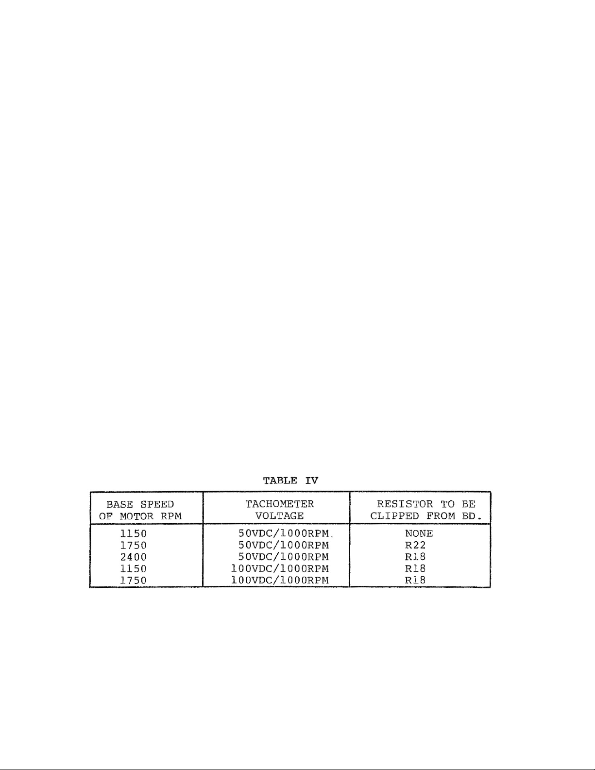
a) Refer to table IV for necessary board modification if any. The control
has been set up to handle the most commonly used base speed motor
and tachometer combinations. Table IV gives the base speed and
tachometer voltage ratings that will work with the board as designed.
For some combinations, a resistor must be clipped from the board. For
motor and tachometer combinations not covered in this manual,
consult the Polyspede factory.
19
Page 23
b) Connect the tachometer leads so that the positive lead connects to
terminal 9 (“TACH”) and the negative side to terminal 5 (“COM”). If
the drive system is connected for reversing (open chassis control
systems), the tachometer leads must be reversed when motor rotation
is reversed so that terminal 9 is always positive in respect to common.
Polarity can be easily checked by running the control connected for
armature voltage feedback, and checking the tachometer for voltage
polarity as specified.
c) With the control off, the jumper connecting pins 1 and 2 on the
feedback select 2PL should be changed to connect pins 2 and 3. ( The
jumper can be removed by vertically sliding the jumper off the plug
pins.)
d) Set the IR pot to zero, fully counterclockwise position. Failure to do so
can cause drive instability when using tachometer feedback.
e) When running using tachometer feed back, it will probably be
necessary to readjust the “MAX SPEED” adjustment. Rotate the
“MAX” speed fully counterclockwise. Set the speed potentiometer for
maximum speed. Adjust the “MAX” potentiometer clockwise until
motor reaches desired maximum speed or until voltmeter reads 180
volts, whichever occurs first.
20
Page 24

15. MAINTENACE – CONTROL
The control requires practically no maintenance once it has been installed. It is a
rugged piece of equipment, but can be damaged if abused.
IF FUSE REPLACEMENT BECOMES NECESSARY, USE ONLY
THE SPECIFIED FUSES. THE USE OF A SUBSTITUE FUSE
MAY CAUSE CONTROL DAMAGES AND VOID THE
CONTROL WARRANTY.
Correct fuses to be used are listed in Table I on page 3 of this manual.
16. MAINTENACE – MOTOR
Motors supplied by Polyspede are rugged machines specifically designed for
SCR controllers. There are no adjustments to make and maintenance is quite
simple. All moving parts are subject to wear. Brushes are perhaps the only
component requiring periodic maintenance.
Motor brush life is related to motor speed, loading, cycling rate, ambient
temperature, and other variables not controlled by Polyspede. Therefore, only
guidelines can be given for checking this item. Experience has shown that each
application has its own wear rate. Removal of the brushes after each three
months of operation during the first year will give an indication of your specific
wear rate. After three sets of brushes have been used, remove the motor
armature for checking by a competent motor repair shop for possible
commutator refacing.
Armature bearings are sealed and require no additional lubrication.
Replacement should be performed by a reputable service shop, if they become
noisy.
Occasional cleaning of motor vent holes or removal of fan guard to remove dust
accumulation from fans is the only additional maintenance required.
17. MAINTENANCE – SPEED REDUCER
a) Use type and grade oil specified on the gear reducer nameplate. Keep
in mind proper viscosities for various temperatures.
b) Keep oil at proper level.
c) Drain, flush, and refill reduction unit after initial run-in period.
21
Page 25

d) Replace shaft seals at first sign of leakage, not only to avoid damage
due to loss of lubricant, but also to eliminate the possible entrance of
contaminants into housing
e) If detailed instructions for assembly and disassembly of a particular
unit are required, write the speed reducer factory for the information.
f) If your drive is coupling a connected, and requires lubricating, the
coupling should be checked on start-up and semiannually.
22
Page 26
Page 27
Page 28
Page 29
Page 30
Page 31
Page 32
 Loading...