

Page 1

OPERATING,
PROGRAMMING AND
MAINTENANCE MANUAL
POWER SOURCE PS 254
Page 2

LIMITS OF WARRANTY
Original features of the equipment and maintenance
The liability of the Polysoude company for delivered welding equipment is ending
immediately if:
- One or several components have been removed, distorted or altered without permission
in writing from the manufacturer, especially concerning safety facilities, electronic circuit
design or fluid systems...
- The essential maintenance procedures necessary for the faultless operation of the
machine have not been carried out.
Transformation of the original designation of the equipment
If approved equipment is used by the purchaser or a third party as part of a special
machine or an assembly line, instead of an examination part after part the responsible
party has to prove the conformity of the entire unit.
Consequently in this case the liability of Polysoude is released; the purchaser or the third
party has to take the engagements of a builder and to satisfy all applicable legal
requirements.
Stability of the machines
The stability of the machines has to be assured by strictly respecting the handling and
transport procedures specified by Polysoude (refer particularly to the specific chapter in
the Operating and Maintenance Manual).
Handling conditions
To move or displace equipment, the lifting eyebolts or integrated connection rods have to
be used.
In order not to overcharge lifting equipment, the operator must know the weight of the
equipment.
2002 Polysoude
Original edition: Polysoude S. A. Nantes France
All rights reserved. No part of this manual may be reproduced in any form or by any
electronic or mechanical means, including information storage and retrieval systems,
without permission in writing from the publisher, except by a reviewer who may quote
brief passages in a review.
Printed in France.
Published by Polysoude, Nantes, France.
www.polysoude.com [email protected]
2 MAN. PS 254 EN – Ind. 2
Page 3

Index
1. INTRODUCTION ..................................................................................................................... 5
1.1. The PS power sources ......................................................................................................... 5
1.2. The orbital welding heads ..................................................................................................... 6
1.2.1. The open welding heads................................................................................................ 6
1.3. The tube to tubesheet welding heads.................................................................................... 6
1.3.1. The closed chamber weld heads.................................................................................... 7
1.4. Technical specifications of the power source PS 254............................................................ 8
1.4.1. Design features............................................................................................................. 8
1.4.2. The remote control pendant ........................................................................................... 9
1.4.3. Technical characteristics ............................................................................................. 10
1.4.3. Technical characteristics ............................................................................................. 10
1.5. Safety precautions.............................................................................................................. 11
1.5.1. General rules............................................................................................................... 11
1.5.2. Training of the operators.............................................................................................. 11
1.5.3. Maintenance and adjustments ..................................................................................... 11
1.5.4. Ergonomics ................................................................................................................. 11
1.5.5. Protection during breakdown or incidents..................................................................... 11
1.5.6. Electric disconnect or shut off devices ......................................................................... 11
1.5.7. Fire prevention and explosion protection...................................................................... 11
1.5.8. Protection against burns .............................................................................................. 11
1.5.9. Gases and vapors ....................................................................................................... 11
1.5.10. Failure elimination.................................................................................................... 12
2. INSTALLATION..................................................................................................................... 13
2.1. Preparation of the PS 16 .................................................................................................... 13
2.2. Installation.......................................................................................................................... 14
2.2.1. Handling...................................................................................................................... 14
2.2.2. Installation................................................................................................................... 14
2.2.3. Input power connection................................................................................................ 14
2.2.4. Connection with gas supply ......................................................................................... 15
2.3. Preparation for work ........................................................................................................... 15
2.3.1. Connection of the remote control pendant.................................................................... 15
2.3.2. Connection of an MU welding head or a TP or TS tube/tubeplate welding head ........... 15
2.3.3. Connection of an air cooled closed chamber welding head .......................................... 16
2.3.4. Connection of a liquid cooled closed chamber welding head ........................................ 17
2.3.5. Connection of a wire feed unit ..................................................................................... 17
2.3.6. Connection of a manual torch with double command ................................................... 18
2.3.7. Connection of a liquid cooled closed chamber welding head with tachometry (optional) 18
2.4. Controls ............................................................................................................................. 19
2.4.1. Front panel .................................................................................................................. 19
2.4.2. Synopsis ..................................................................................................................... 20
2.4.3. The remote control pendant ......................................................................................... 21
3. OPERATION OF THE PS 254 ............................................................................................... 22
3.1. Fundamental procedures.................................................................................................... 22
3.1.1. Switching on................................................................................................................ 22
3.1.2. Positioning the welding head on the workpiece ............................................................ 22
3.1.3. Wire setting................................................................................................................. 22
3.1.4. Adjustment of the gas flow........................................................................................... 22
3.1.5. Manual cooling system start ........................................................................................ 22
3.2. Programmation surface ...................................................................................................... 23
3.3. Programming ..................................................................................................................... 24
3.3.1. Entering the program name ......................................................................................... 25
3.3.2. Modifying the program name ....................................................................................... 25
3.3.3. Choice of a built-in program......................................................................................... 26
3.3.4. Programming and modifying the welding parameters ................................................... 27
3.3.5. Programming of sectors............................................................................................... 43
3.3.6. Deleting a program from the source memory ............................................................... 46
3.3.7. Entering the time and date........................................................................................... 47
3.3.8. Entering / modifiying the company name ..................................................................... 47
MAN. PS 254 EN – Ind. 2 3
Page 4

3.3.9. Saving, loading a program........................................................................................... 48
3.3.10. Printing a program ................................................................................................... 49
3.3.11. Programmable parameters....................................................................................... 50
3.4. Execution of a weld program .............................................................................................. 52
3.4.1. Safety precautions....................................................................................................... 52
3.4.2. Choosing the program to be executed ......................................................................... 52
3.4.3. Simulation ................................................................................................................... 52
3.4.4. Weld cycle................................................................................................................... 52
3.4.5. End of welding cycle.................................................................................................... 53
3.4.6. Manual weld cycle stop................................................................................................ 53
4. SERVICING, MAINTENANCE AND TROUBLESHOOTING ................................................... 55
4.1. Servicing ............................................................................................................................ 55
4.1.1. Adjustments ................................................................................................................ 55
4.1.2. Adjustment of the inverter unit ..................................................................................... 57
4.1.3. Adjusting the rotation speed of welding heads with tachometry (optional)..................... 61
4.1.4. Coolant ....................................................................................................................... 62
4.1.5. Printer......................................................................................................................... 62
4.2. Maintenance and troubleshooting ....................................................................................... 63
4.2.1. Replacing fuses...........................................................................................................63
Fig. 4.14: Location of the fuses.................................................................................................. 63
4.2.2. Trouble shooting.......................................................................................................... 64
4.2.3. Spare parts ( See “summary spare parts” pages 84/85) ............................................... 69
4.2.4. Circuit description........................................................................................................ 70
5. APPENDIX ............................................................................................................................ 76
5.1. Built-in programs ................................................................................................................ 76
5.1.1. Closed chamber welding heads or MU heads without filler wire.................................... 77
5.1.2. MU open welding heads with filler wire ........................................................................ 79
5.1.3. TS/TP welding heads for welding of tubes to tubesheet ............................................... 80
5.2. Error codes ........................................................................................................................ 81
CONFIGURATION OF THE DIPS FOR PS 254............................................................................... 82
SUMMARY SPARE PARTS .............................................................................................................85
4 MAN. PS 254 EN – Ind. 2
Page 5
1. INTRODUCTION
1.1. The PS power sources
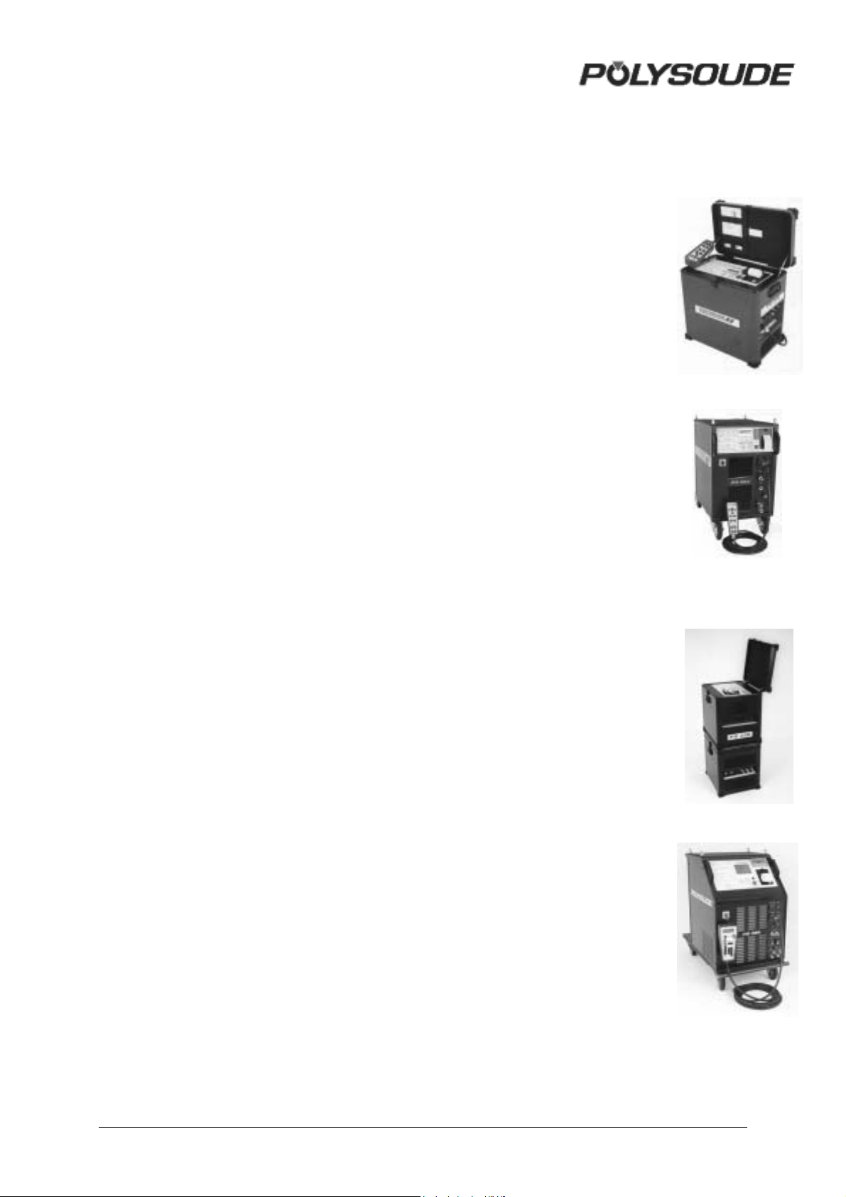
The power source PS 254 belongs to a
versatile new family of universal and easy to
use orbital TIG power sources. Special
features are:
• Welding sequences entirely programmable
in the language of the welder.
• Ease of use due to an intuitive
programming.
• Integrated program library for quick
welding parameter research.
• Real time monitoring system.
• Integrated printer for documentation of
welds according to the ISO 9000 standard.
• Possibility of storing programs in the
memory of the power source or on 3,5"
disk.
• Modern inverter based power source
technology.
• Mechanised welding with the ease and
comfort of PS power sources.
PS 204
Portable 200 A, single phase
input power source.
Ideal for on site use.
PS 254
Power source 250 A.
Ideal for shop, site and subassembly work.
With a weld current range between 1 A and
350 A and up to six programmable axes the
PS power sources respond to a wide field of
applications:
• Pulsed or continuous weld current.
• Travel speed and wire speed continuous
or with pulsation synchronised to the weld
current.
• With Arc Voltage Control AVC, the welding
of several passes without interruption is
possible.
• Oscillation.
• Programmable mass flowmeter for the
shielding gas.
PS 256
Portable power source 250 A.
Comes with AVC and oscillation.
PS 356
Power source 350 A.
Programming like PS 256.
Universality for all welding needs.
MAN. PS 254 EN – Ind. 2 5
Page 6
1.2. The orbital welding heads
r
r
r
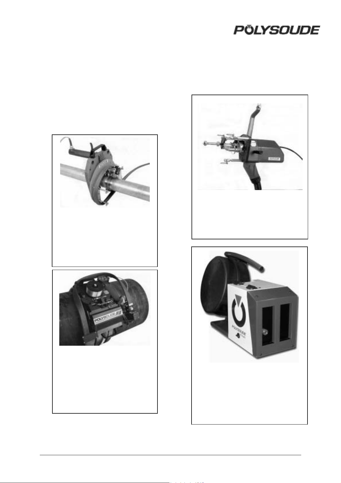
The PS power sources support most of the
Polysoude orbital welding heads.
1.2.1. The open welding heads
• MU IV type for standard applications and
all weld problems where AVC and
oscillation is required.
• Polycar welding carriage to weld large
diameter pipes.
1.3. The tube to tubesheet welding
heads
• TS heads with different productivity to
meet all requirements.
TS 73 the standard welding head for tube
to tubesheet applications.
MU IV AVC/BL with AVC and
oscillation.
Modular design. Microprocesso
controlled AVC and oscillation slides,
driven by precision stepper motors.
POLYCAR welding carriage to weld
large diameter pipes.
Microprocessor controlled AVC and
oscillation. Integrated wire feeder.
Possibility to adapt equipment fo
distance controlled or mechanised
welding processes.
Open welding head for protruding, flush o
recessed tubes.
POLYFIL external wire feeder.
Wire feeder with four roll linear drive
system to minimise wire deformation and
surface distortion.
External wire feeder.
6 MAN. PS 254 EN – Ind. 2
Page 7
1.3.1. The closed chamber weld heads
A
f
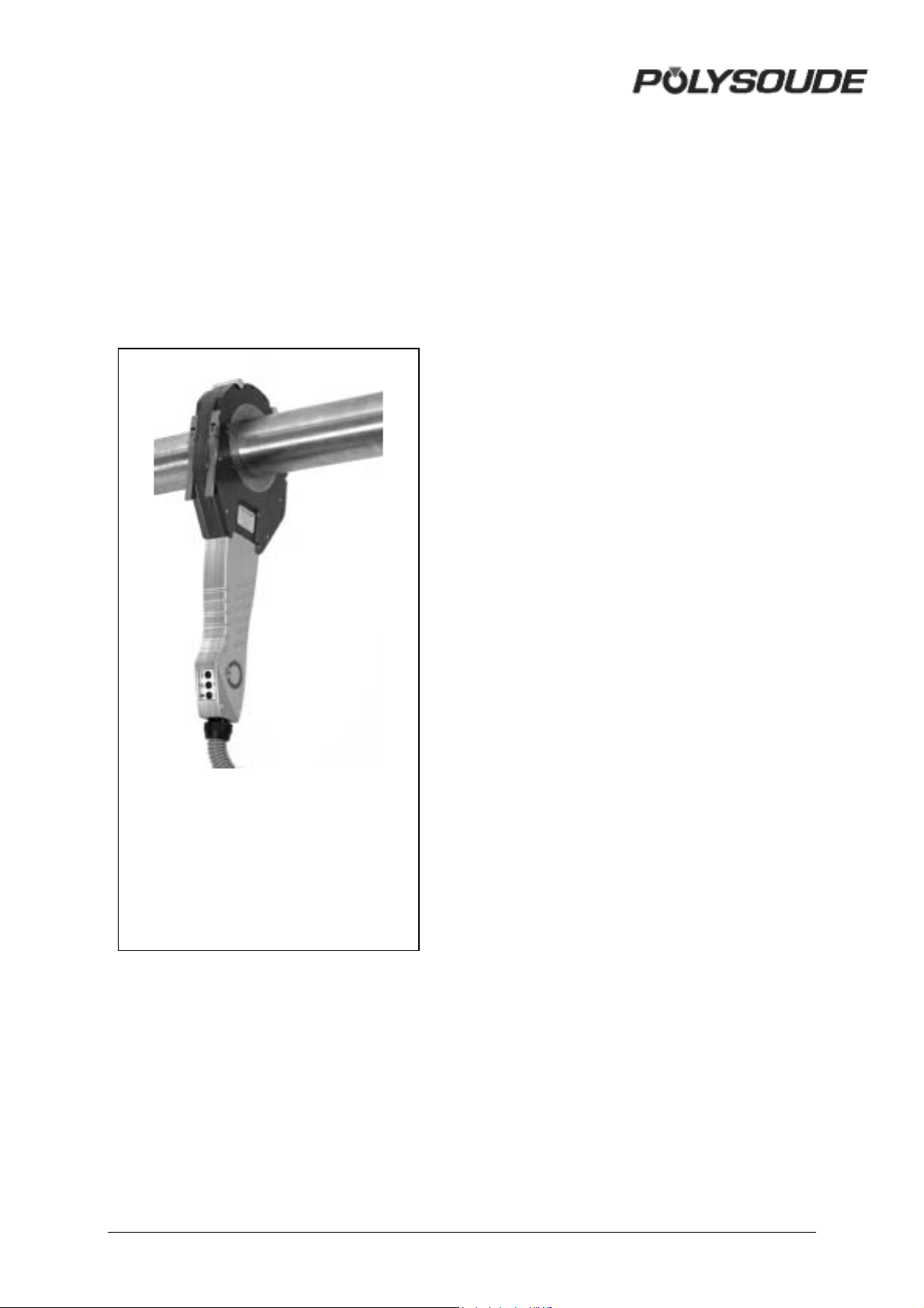
• Sentry UHP for the demands of high purity
industries.
• HD when the access to the weld area is
reduced.
• MW for high production rates.
• K to answer the demand of a very reliable
shielding gas protection.
MW, when high production rates are
required.
High duty cycle due to water cooling.
daption kits for the welding o
accessories (elbows, flanges, valves,
connections, etc.) available.
MAN. PS 254 EN – Ind. 2 7
Page 8
1.4. Technical specifications of the power source PS 254
1.4.1. Design features
The PS 254 was designed especially for
automatic TIG (GTAW) welding. It works with
H type enclosed welding heads and it is
compatible with all standard Polysoude MU III
or IV open welding heads, TS and TP heads
for welding tube to tube plates and K, H, MW
and UHP enclosed heads of the Astro Arc
Polysoude range. The Polyturn positioner and
the Polyfil wire feed unit can be used. Welding
with a manual TIG (GTAW) torch is also
possible.
①
④
⑤
②
③
⑥
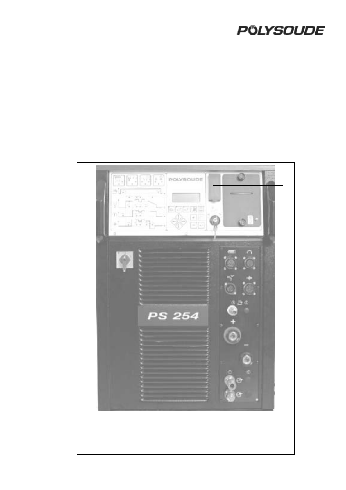
1 Screen 5 Printer
2 Synoptic programmation board 6 Connection panel
3 Key board
4 Memo card drive
8 MAN. PS 254 EN – Ind. 2
Page 9
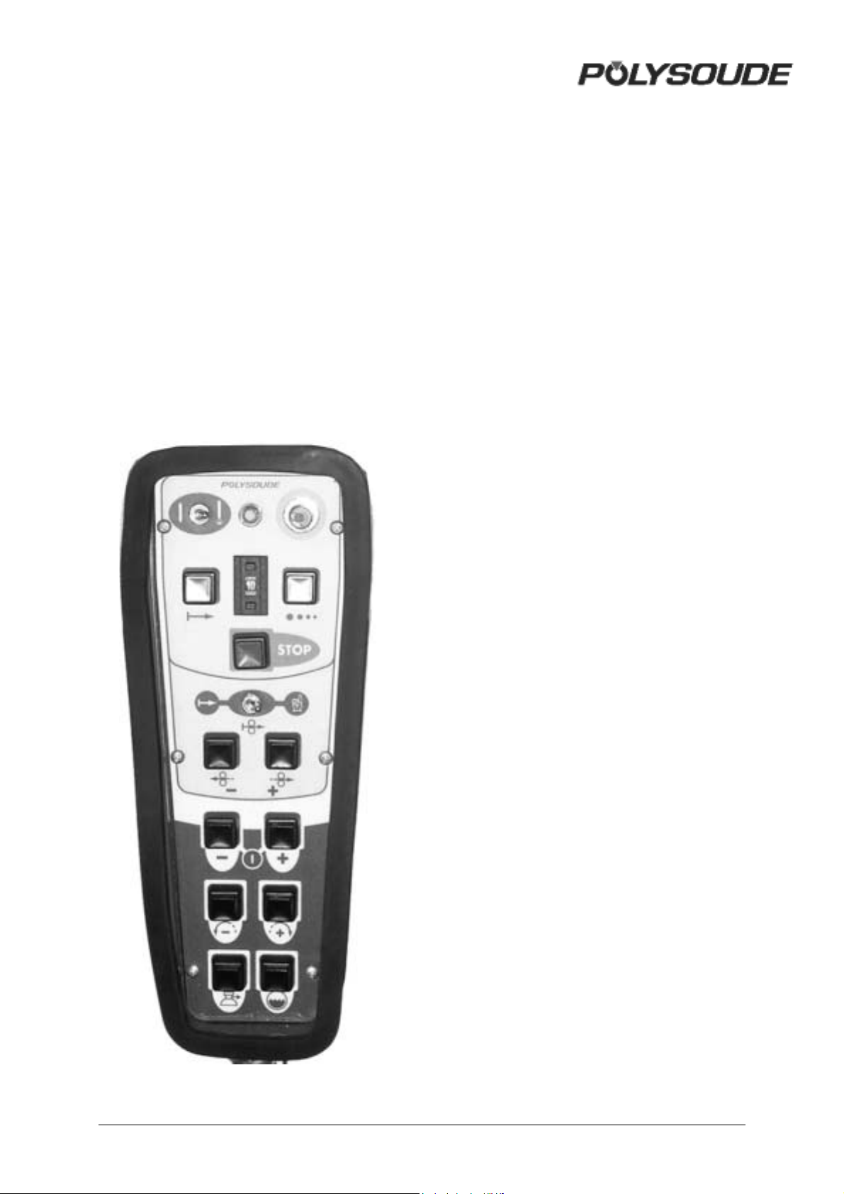
1.4.2. The remote control pendant
This allows:
• The positioning of welding heads and wire
feed units
• The starting and stopping of weld cycles
• The selection of the program to be
executed
• The simulation of a cycle without welding
• Modifications to be made during a cycle
• The shielding gas to be tested
• The manual start of the cooling pump
• The stopping of a cycle in the case of an
emergency.
MAN. PS 254 EN – Ind. 2 9
Page 10
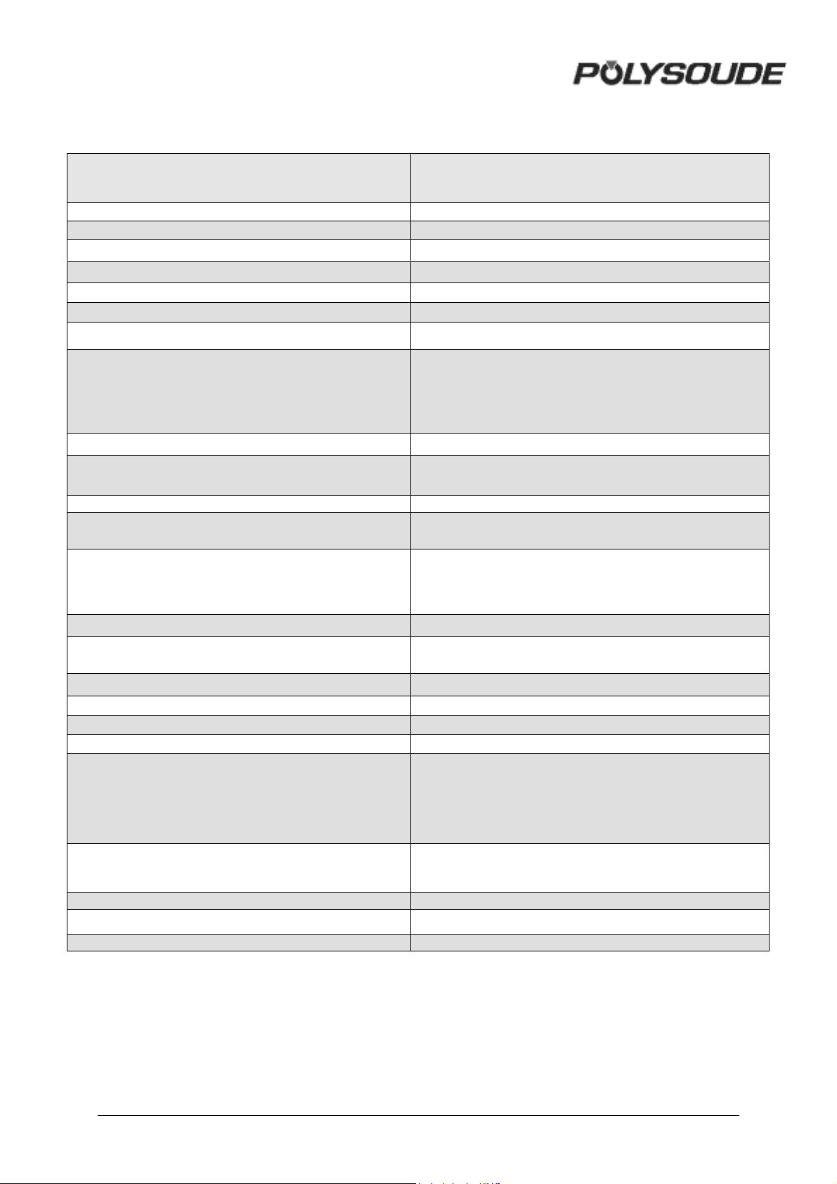
1.4.3. Technical characteristics
Power input
Open circuit voltage
Insulation class
Protection class
Welding current range
Duty cycle
Current resolution
Pulse frequency
Movement controls
Precision on movements
Gas control
Power source cooling
Torch cooling
Display of real values during cycle
Programs in user memory
Display
Program sectors
Program library
Program storage
Auto-diagnostic system
Immediate exploitation
Three phase +ground
400V - (as an option : multi voltage ; 200 – 460 V)
± 10 % 50 or 60 Hz
105 V
F
IP 21 IK04
4 - 250 A D.C.
250 A / 60 % - 190 A / 100 %
1 % when I ≥ 100 A - 1 A when I ≤ 100 A
from 10 to 9999 ms
Direct or pulsed current
Constant or pulsed command of torch rotation
Constant or pulsed wire feed, wire-retract at the end of
the weld
± 1 %
Gas torch with security
second gas (option)
Forced ventilation
By water in closed circuit with flow safety valve
Continuous display:
. of arc voltage
. of welding current
. of impulses of movements
16
4 lines of 20 characters, with 8 characters reserved to
the designation of programs
10 maximum
60
On memory card
Display of code number
with welding heads :
. tube/plate
. tube/tube MU* - MW - H - K, UHP
. direct use of wire feeder Polyfil
. PO motor mechanised application
Specific functions
Size L x W x H (mm)
Weight
Standard
10 MAN. PS 254 EN – Ind. 2
Possibility of connecting a manual TIG torch
As an option : possibility of controlling welding heads
with tachometer feedback
890 x 500 x 890
100 kg
EN 60974-1/EN 50199
Page 11

1.5. Safety precautions
1.5.1. General rules
All aspects of work should be planned with
caution. To carry it out, safety related actions
are continuously required.
All hook up or maintenance operations
described in this manual, which may be
harmful, are always indicated by the
ATTENTION symbol.
Warning Situation with the risk to
injure persons or even
danger of life
Procedures to avoid malfunction or damage of
equipment are indicated by the mention Note.
1.5.2. Training of the operators
One copy of the operating and maintenance
manual is always delivered with the equipment.
The different operators (welder, controller,
maintenance people, ...) must always have at
their disposal at least one spare copy (respect
the copy right). The qualification they need for
their work depends on the level of
responsibility they carry during their mission.
1.5.3. Maintenance and adjustments
If maintenance or adjustment work has to be
carried out on the upper parts of the
equipment, a scaffold has to be erected.
It is strictly forbidden to pull on cables or hoses
to move welding heads or the power source or
to push on consoles or panels.
1.5.4. Ergonomics
! Identification
Identification by means of colours, especially
on safety relevant elements like buttons or pilot
lamps, must not be altered or changed.
Components with worn out colours have to be
replaced.
! Lighting of the work area
Lighting equipment should give regular light
without spots or too much light concentration.
Glare-free light without deep shadows can help
to avoid fatigue of the operators.
1.5.5. Protection during breakdown or
incidents
Before taking action in the case of a
breakdown or incident, the machines must be
disconnected from the power supply.
1.5.6. Electric disconnect or shut off
devices
! Disposition of equipment isolators
The presence of electric disconnect or shut off
devices is imposed by law. In case of mobile
equipment or when Polysoude supplies only a
part of the entire machine, the customer is
responsible to install the necessary missing
devices.
! Operation of electric disconnect or shut
off devices
Before electric disconnect or shut off devices
are operated, it has to be checked that this
action is of no danger for operators or visitors.
1.5.7. Fire prevention and explosion
protection
The working environment for the welding
machines must be free of combustible material
and solvents.
The PS 254 should never be used for the
purpose of defrosting.
1.5.8. Protection against burns
Operators and visitors must wear protection
against sparks.
1.5.9. Gases and vapors
A sufficient ventilation has to be installed in the
workshop to avoid health hazards caused by
gases or vapors generated during the weld
process. A protection against the radiation
emitted from the arc has to be worn.
MAN. PS 254 EN – Ind. 2 11
Page 12

1.5.10. Failure elimination
Only qualified electricians are allowed to work
on electric or electronic equipment of the
welding machines and their connection to the
power supply.
Directly before beginning any work, the
isolation from the power supply has to be
controlled.
Warning Electric or electronic devices
may be under high voltage
even when disconnected
from the power supply.
Capacitors keep their charge
during a long period of time.
It is forbidden to alter or remove safety devices
from the machines.
Working on electric devices is only allowed
when standing on a dry floor. Avoid the
penetration of liquids to electric devices.
In the area around welding machines, solvants
and combustible liquids are not allowed.
Watches, jewelry and bracelets may not be
worn during interventions on electric devices.
12 MAN. PS 254 EN – Ind. 2
Page 13
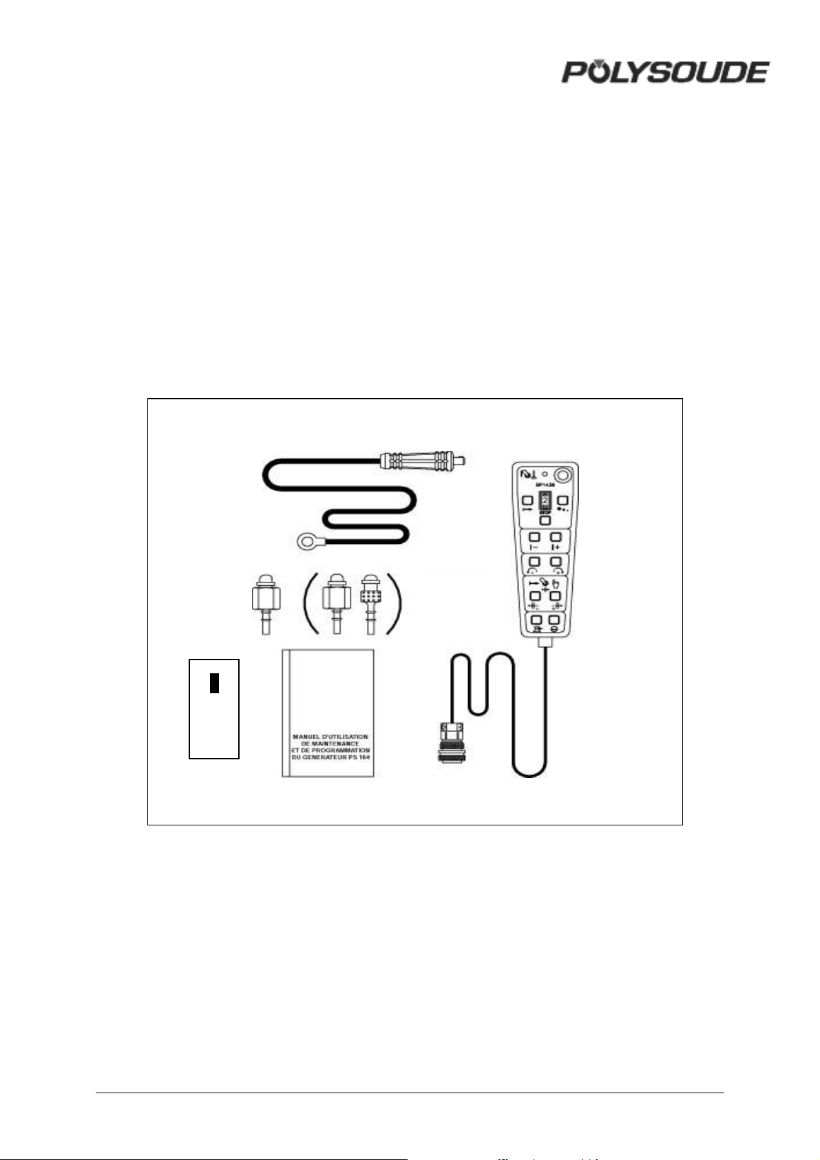
2. INSTALLATION
2.1. Preparation of the PS 254
The PS 254 is delivered in a transport
protection case. You will find:
• The remote control pendant BP 1436 or
BP 1737(1).
• A ground cable 9 m (30') in length (2).
②
③
⑤
④
• A gas connection (two other ones in case
of an optional second gas) (3).
• This operating and maintenance
manual (4).
• One memo card (5).
•
•
•
•
•
•
•
•
•
•
•
•
•
•
•
•
•
•
•
•
•
①
Fig. 2.1 : Accessories of the PS 254
MAN. PS 254 EN – Ind. 2 13
Page 14
Warning Do not move the PS 254 with
a fork-lift truck if it is not
place on its original pallet.
2.2.2. Installation
For safe work the PS 254 has to be placed
horizontally, on a firm surface. In this case a
shaft system ensures the stability of the
machines.
Openings are provided for ventilation of the
power source. To ensure effective cooling of
the system, a minimum distance of 30 cm (12")
should be maintained between these openings
and any surface.
2.2.3. Input power connection
Warning All connections must be
made by a qualified
technician respecting the
General
safety rules given by law or
quoted in this manual.
The PS 254 is connected to the main power
supply with a cable of 3 conductors + ground,
which comes with the machine (length 3,5 m).
It is essential to connect the ground cable
correctly in order to ensure the safety of the
operators.
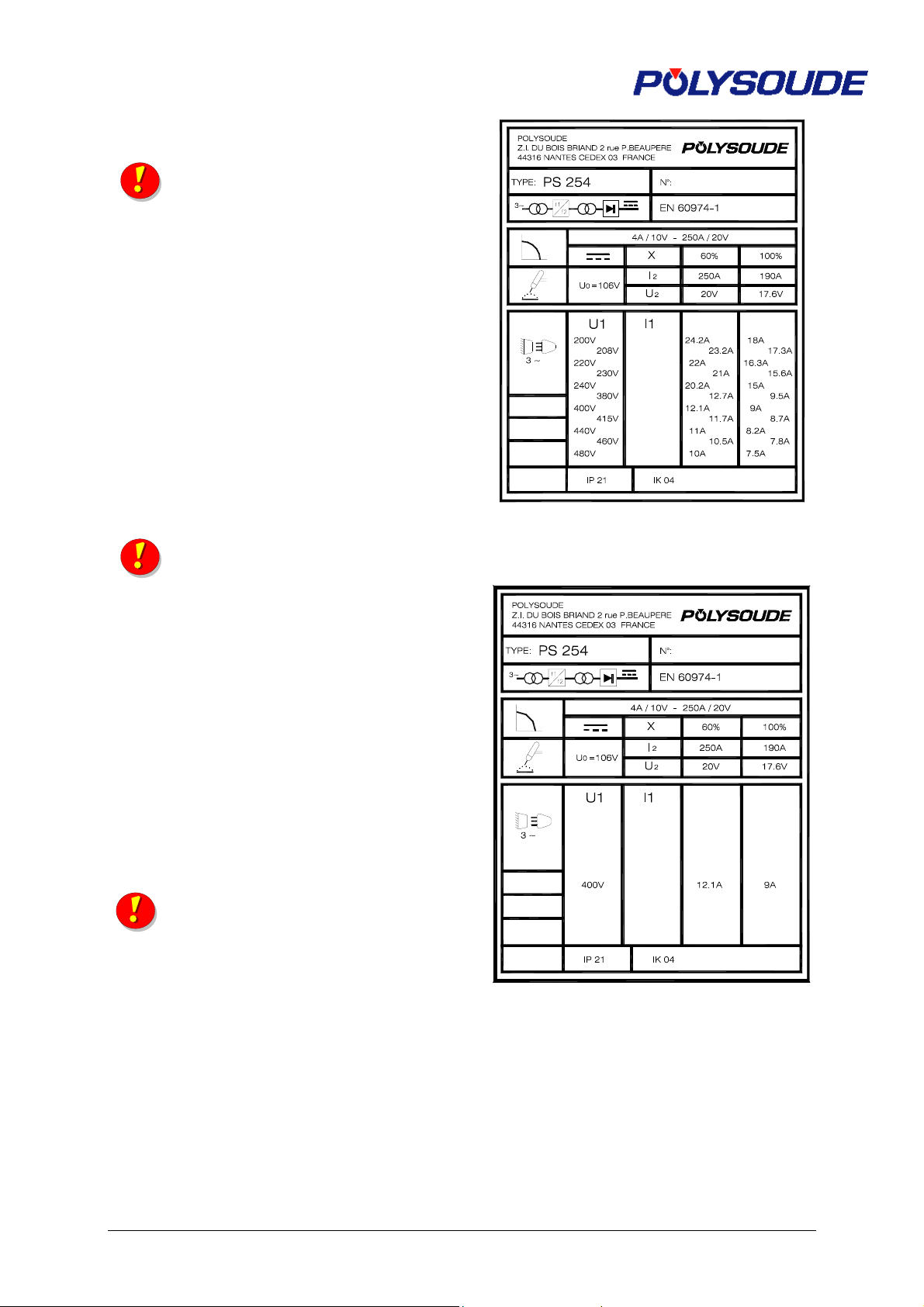
Refer to the name plate of your power source
for input power requirements. For example, to
work with an input voltage of 230 V, a 21 A
fuse is required.
Warning It is essential to connect the
ground cable in order to
ensure the safety of the
operators.
Fig. 2.2 : Name plate of the PS 254
multivoltage
Fig. 2.3 : Name plate of the PS 254 single
voltage
14 MAN. PS 254 EN – Ind.2
Page 15
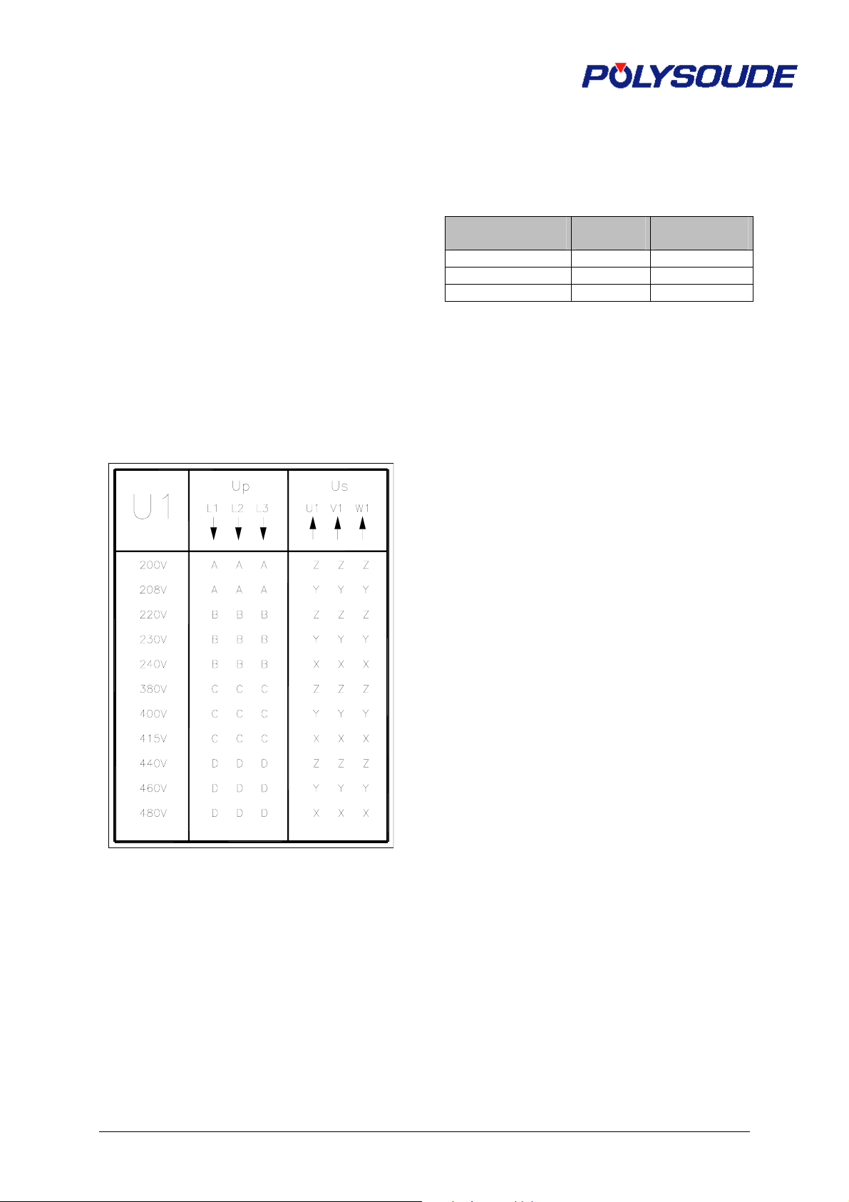
Input voltage taps
Do not consider this paragraph if the PS 254
has to be connected in 400 V only.
In the case of a PS 254 fitted out with the
multivoltage kit, the input power jumpers must
be set correctly before it is switched on. The
input power of the power source is 500 V when
it is delivered to you.
Coupling is made on the terminal connection of
the power transformer. Unscrew the four
shackles on the top of the power source and
remove the roof in order to get access. Before
proceeding on any electrical part, make sure
the machine is not connected to the electrical
mains supply.
The power transformer being three-phase,
coupling has to be made in these three
different points.
wire to the “+” terminal if your voltage is too
high or to the “-“ terminal if it is too low.
Refer to the following table to know the
acceptable variations depending on
connections and nominal voltage (Un).
MAXIMUM
CONNECTION
MAXIMUM
VOLTAGE
MINIMUM
VOLTAGE
U Un + 10 % Un – 10%
- Un + 5 % Un – 15 %
+ Un + 20 % Un
Fig. 2.4 : Input voltage taps
The value of the mains voltage is beyond
standards.
The PS 254 is designed to work with a mains
voltage which can fluctuate by ± 10 % from the
nominal value. If the mains voltage of your
equipment is not comprised within this range,
you can intervene. In the connection terminal
situated near the transformer,move the "U"
MAN. PS 254 EN – Ind. 2 14 bis
Page 16
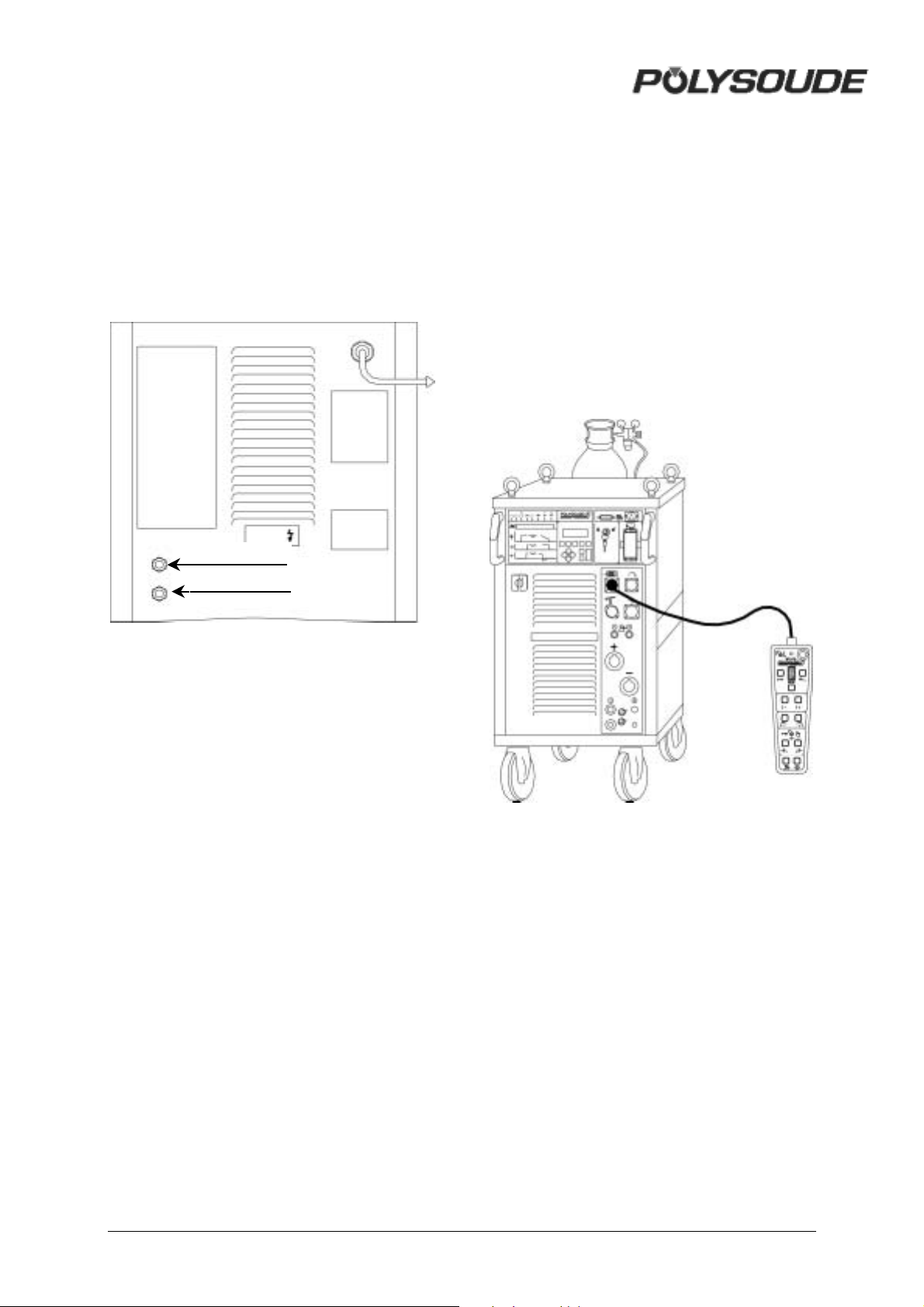
2.2.4. Connection with gas supply
Connection with the gas supply is made at the
rearside of the power source with the
appropriate fittings. Flow regulators should be
used to adjust the power source inlet gas
stream to the correct value (see appendix 4 Spare parts). Before making any connections,
briefly open the valves to drive out any
impurities.
Gaz 1
Gaz 2 (option)
2.3. Preparation for work
2.3.1. Connection of the remote control
pendant
Connection of the remote control pendant is
made with the plug on the right side of the PS
254 on the screw connector.Make sure the
securing ring is tightened properly, otherwise
the system may not function correctly.
Warning: the power source will not work if the
remote control pendant is not properly
connected.
Fig. 2.4 : Gas connections at the right
side of the PS 254
Fig. 2.5 : Connection of the remote
control pendant with the PS 254
2.3.2. Connection of an MU welding head
or a TP or TS tube/tubeplate welding head
Liquid cooled welding heads of these types
need to be used with the integral cooling unit.
! Connection of the electrode current
cable
Connect the current cable on the "-" terminal
with the quick connector, locking it by a short
rotation to the right.
MAN. PS 254 EN – Ind. 2 15
Page 17
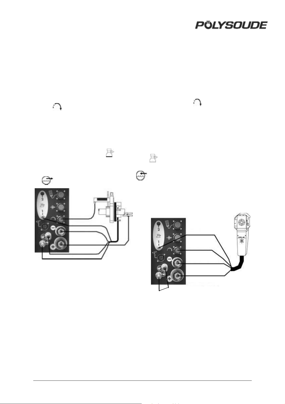
! Connection of the current return cable
Connect the current return conductor cable
onto the "+" terminal marked by a red ring.
Connection is made with a quick connector, by
a short rotation to the right. Connect the other
end of the cable to the workpiece, as close as
possible to the joint to be welded, in an area
free from grease and oxide.
! Connection of the rotation motor cable
Join the cable on the "Rotation" connector
(symbol ). Make sure that the securing ring
is properly tightened, otherwise the system
may not function correctly.
! Connection of the torch shielding gas
hose
Connection is made with a quick push-type self
sealing coupling situated at the connection
plate of the power source (symbol ).
! Connection of the coolant circuit
Connection is made by 2 quick push type self
sealing couplings on the front view (symbols
and ).
! Connection of the current return cable
Connect the current return conductor cable
onto the "+" terminal marked by a red ring.
Connection is made with a quick connector by
a short rotation to the right. This cable is
indicated red.
! Connection of the rotation motor cable
Connect the cable on the "Rotation" module
connector (symbol ). Make sure that the
securing ring is properly tightened, otherwise
the system may not function correctly
! Connection of the torch shielding gas
hose
Connection is made with a quickpush type self
sealing coupling disconnect fitting situated at
the bottom left hand corner of the front panel of
the PS 254 (symbol
").
! Connection of a bipass plug for the
coolant circuit security for use with air
cooled welding heads.
It is necessary to introduce the bipass plug to
isolate the cooling circuit security in order to
avoid a continuously detected fault.
Torch rotati on
connection
Gas coupling
Electrode connection
Workpiece connection
Water coupling
Water coupling
Fig. 2.6 : Connection of an MU welding
head or a TP/TS welding head
2.3.3. Connection of an air cooled closed
chamber welding head
Connection of an air cooled closed chamber
welding head
! Connection of the electrode current
cable
Connect the current cable on the "-" terminal
with the quick connector, locking it by a short
rotation to the right. This cable is not indicated.
Gas coupling
Torch rotation connection
Electrode connection
Workpiece connection
Shunt supplied with H heads
Fig. 2.7 : Connection of an air cooled
closed chamber welding head
16 MAN. PS 254 EN – Ind. 2
Page 18
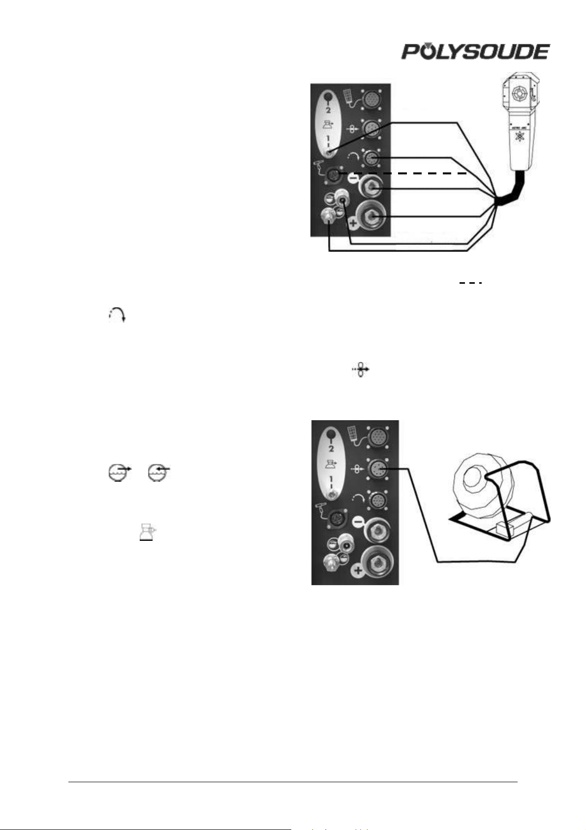
2.3.4. Connection of a liquid cooled
closed chamber welding head
This is the case for type K and MW Astro Arc
Polysoude closed welding heads.
Gas coupling
! Connection of the electrode current
cable
Connect the current cable on the "-" terminal
with the quick connector, locking it by a short
rotation to the right.
! Connection of the current return cable
Connect the current return conductor cable to
the "+" terminal with the quick connector,
locking it by a short rotation to the right. This
cable is indicated red.
! Connection of the rotation motor cable
Join the cable to the "Rotation" connector
(symbol ). Make sure that the securing ring
is tight otherwise the system may not function
correctly.
! Connection of the manual command
cable on the head (MW heads)
Connect the manual commands cable on the
FA 5 terminal (Fig. 2.12) on the connection
plate.
Torch rotation connection
Manual commands cable
Electrode connection
Workpiece connection
Water outlet
Water retu rn
Fig. 2.8 : Connection of a liquid cooled
closed chamber welding head ( for
heads with integrated commands)
2.3.5. Connection of a wire feed unit
The wire feed unit is connected at the
connection panel of the PS 254
(symbol ). Make sure that the securing ring
is tight otherwise the system may not function
correctly.
! Connection of the coolant circuit
Connection is made by 2 quick push type self
sealing couplings on the cooling unit RC 200
(symbols and ).
! Connection of the torch shielding gas
Connection is made with a quick disconnect
fitting situated at the connection panel of the
PS 254 (symbol
").
Fig. 2.9 : Connection of a wire feed unit
MAN. PS 254 EN – Ind. 2 17
Page 19
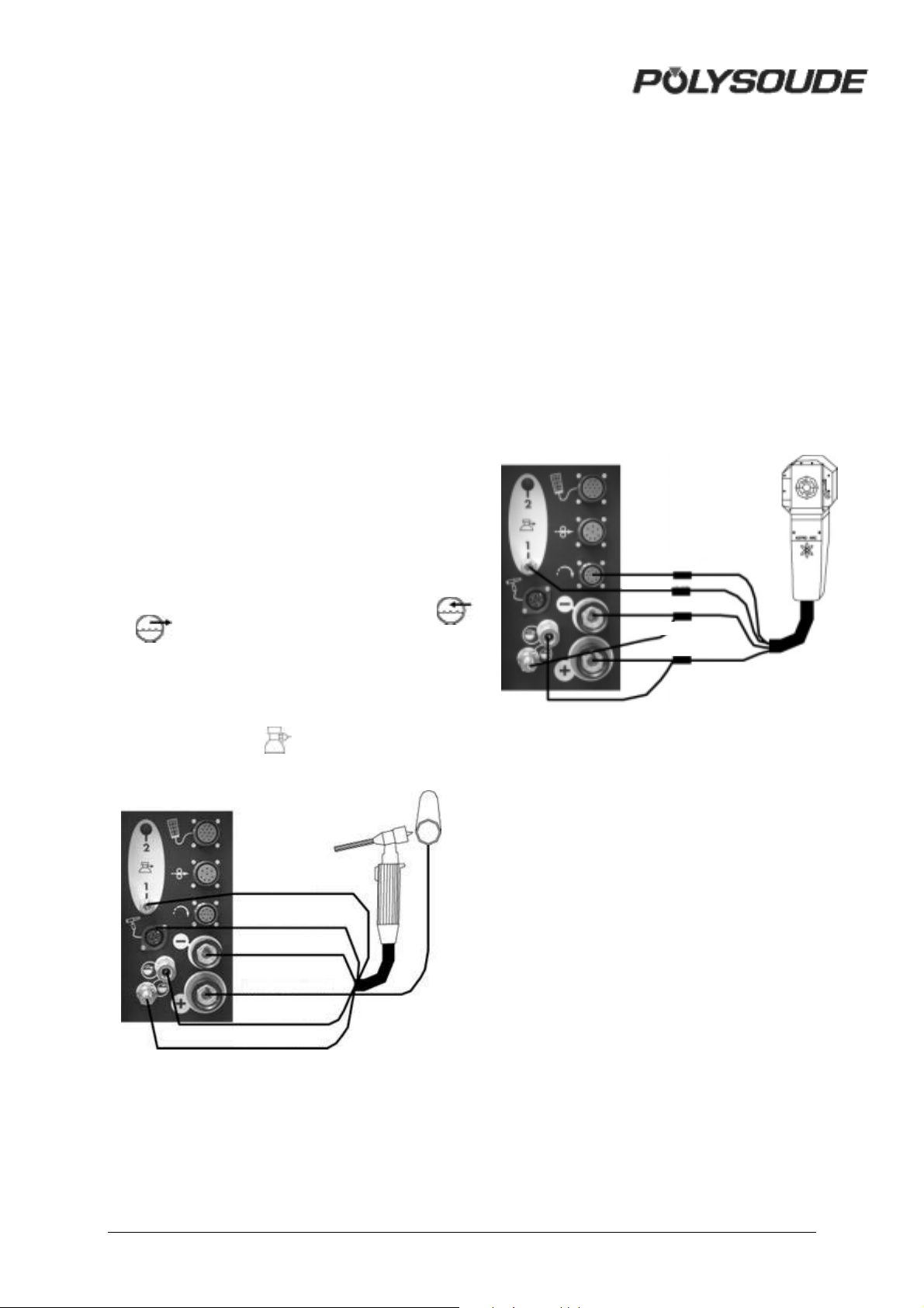
2.3.6. Connection of a manual torch with
double command
! Connection of the electrode current
cable
Connect the current cable on the "-" terminal
with the quick connector, locking it by a short
rotation to the right.
! Connection of the ground cable
Connect the ground cable to the "+" terminal
surrounded by a red ring. Connection is made
with a quick connector, with right hand locking.
Connect the other end of the cable to the
workpiece, as close as possible to the joint to
be welded, in an area free from grease and
oxide.
! Connection of the command cable
The command cable of the manual torch has
to be joined to the socket FA 5 (Fig. 2.12).
! Connection of the coolant circuit
Connection is made by 2 quick push type self
sealing couplings on the front panel (symbols
and ).
! Connection of the torch shielding gas
hose
Connection is made with a quick push-type
coupling located on the connection plate of the
power source (symbol
" ).
2.3.7. Connection of a liquid cooled
closed chamber welding head with
tachometry (optional)
Adapters are mounted between every circuit
from welding head and connections on power
source :
• Gas circuit.
• Torch rotation.
• Electrode connection and water return.
• Workpiece connection and water outlet.
Connections of these adapters on the power
source are identical with those of a liquid
cooled closed chamber welding head.
Torch rotati on
Gas
Electrode connection
Water retu rn
Workpiece connection
Water outlet
Fig. 2.11 : Connection of a liquid cooled
closed chamber welding head with
tachometry
Gas coupling
Torch command connection
Electrode connection
Workpiece connection
Water outlet
Water retu rn
Fig. 2.10 : Connection of a manual torch
18 MAN. PS 254 EN – Ind. 2
Page 20
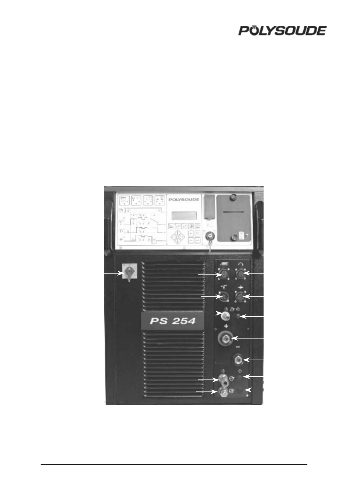
2.4. Controls
2.4.1. Front panel
FA 1 On/off switch.
FA 2 Connection for the remote control
pendant cable.
FA 3 Connection for the rotation motor
cable.
FA 4 Connection for the wire feed unit cable.
FA 5 Connection for manual torch
commands or for manual commands
for MW heads.
FA 6 Connection of a second gas inlet
[backing gas] (option).
FA 7 Connection for a second gas [bac king
gas] (option).
FA 8 Connection of the torch shielding gas
inlet.
FA 9 Connection for the torch shielding gas.
FA 10 Connection for the ground cable.
FA 11 Connection for the electrode cable.
FA 12 Coolant outlet.
FA 13 Coolant return.
FA 1 FA 3
FA 2
FA 5
FA 4
FA 6
FA 7
FA 8
FA 9
FA 10
FA 11
Fig. 2.12 : Front panel
FA 12
FA 13
MAN. PS 254 EN – Ind. 2 19
Page 21
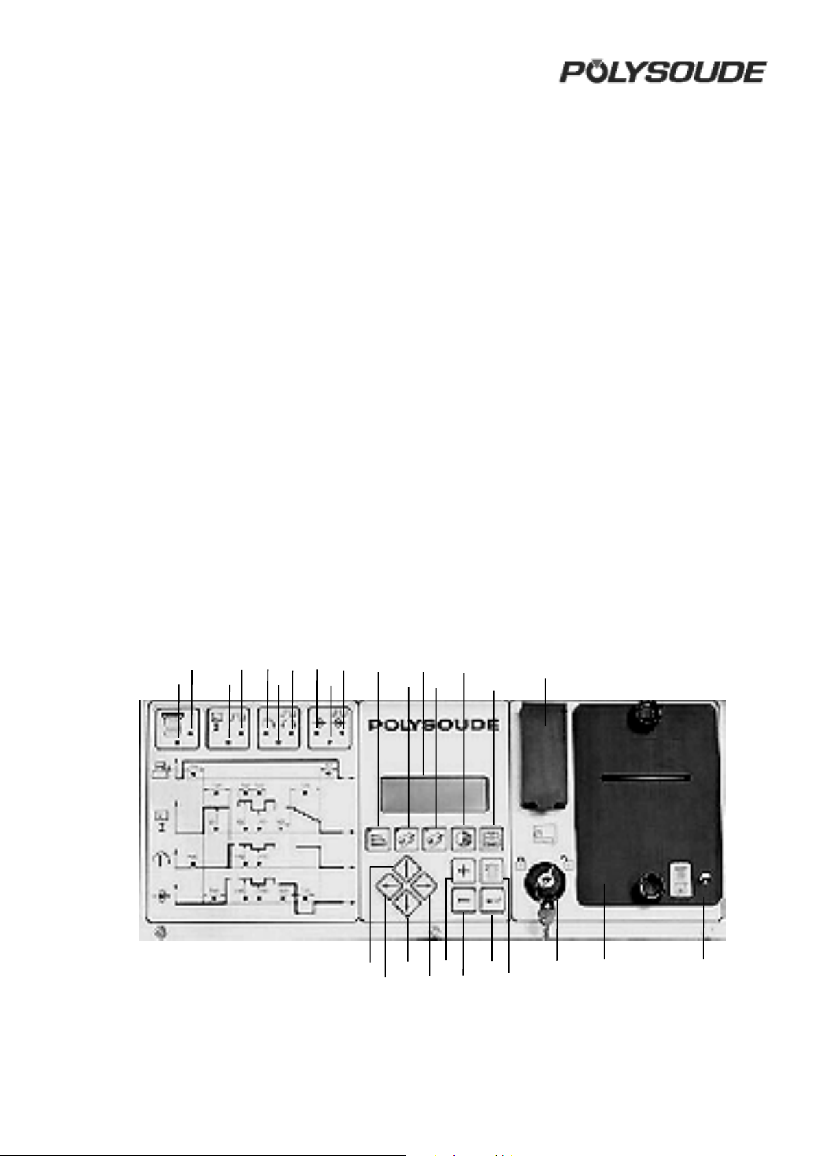
2.4.2. Synopsis
SY 1 Indicator "Printer mode".
SY 2 Indicator "Print report when weld cycle
is finished".
SY 3 Indicator "Current mode".
SY 4 Indicator "With pulsed current".
SY 5 Indicator "Forward rotation".
SY 6 Indicator "Rotation mode".
SY 7 Indicator "Pulsed rotation speed".
SY 8 Indicator "With wire ".
SY 9 Indicator "Wire pushing mode".
SY 10 Indicator "Pulsed wire speed".
SY 11 Print a program key and indicator
"Printing in process".
SY 12 Loading a program from the memo
card key and indicator "Loading in
process".
SY 13 Saving a program on the memo card
key and indicator "Saving in process".
SY 14 Key to program sector positioning or
for entering the date, time and name of
your company.
SY 15 Key to choose built-in programs from
the machine memory.
SY 16 Keys for moving inside the synoptic.
SY 17 Keys for moving inside the synoptic.
SY 18 Keys for moving inside the synoptic.
SY 19 Keys for moving inside the synoptic.
SY 20 Key for increasing parameter values.
SY 21 Key for decreasing parameter values.
SY 22 Enter key.
SY 23 Key for deleting programs or sectors
(trash can).
SY 24 Screen
SY 25 Key operated switch "Modification
permitted or not".
SY 26 Port for memo card.
SY 27 Printer.
SY 28 Paper advance / reprint weld cycle
report.
SY 1
SY 2
SY 3
SY 4
SY 5
SY 6
SY 7
SY 8
SY 9
SY 10
SY 11
SY 16
SY 17
SY 24
SY 14
SY 12
SY 18
SY 13
SY 20
SY 19
SY 21
SY 15
SY 22
SY 23
Fig. 2.14 : Synopsis
SY 26
SY 25
SY 27
SY 28
20 MAN. PS 254 EN – Ind. 2
Page 22
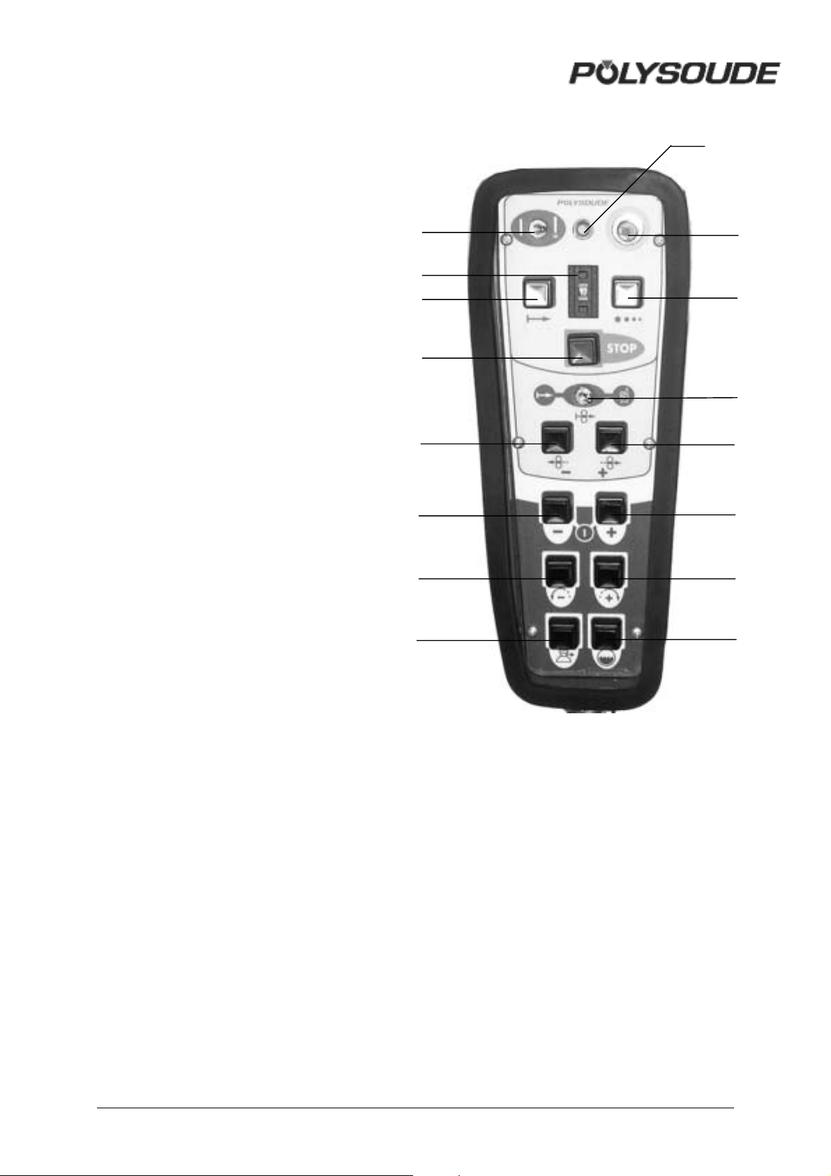
2.4.3. The remote control pendant
BT 1 Selection switch - "Set up / weld".
BT 2 Emergency stop button.
BT 3 Indicator
Illuminated : Cycle in process.
Flashing : Fault detected.
BT 4 Switch for selecting the number of a
user program.
BT 5 Push button "Start cycle".
BT 6 Push button "Stop cycle with
downslope".
BT 7 Push button "Stop cycle immediately".
BT 8 Push button "Increase current (+)".
BT 9 Push button "Decrease current (-)".
BT 10 Push button with two functions:
Out of weld cycle: Forward rotation.
During weld cycle: Increase rotation
speed.
BT 11 Push button with two functions:
Out of weld cycle: Backward rotation.
During weld cycle: Decrease rotation
speed.
BT 12 Wire start "Automatic / Manual".
BT 13 Push button with two functions:
Out of weld cycle: Wire forward.
During weld cycle: Increase wire
speed..
BT 14 Push button with two functions:
Out of weld cycle: Wire reverse.
During weld cycle: Decrease wire
speed.
BT 15 Push button to start the cooling pump
"Test cooling circuit".
BT 16 Push button "Gas test".
BT 1
BT 4
BT 5
BT 7
BT 14
BT 9
BT 11
BT 16
BT 3
BT 2
BT 6
BT 12
BT 13
BT 8
BT 10
BT 15
Fig. 2.15 : The remote control pendant
MAN. PS 254 EN – Ind. 2 21
Page 23
3. OPERATION OF THE PS 254
3.1. Fundamental procedures
3.1.1. Switching on
With the installation properly connected (see
chapter 2), turn the switch FA 1 to the position
1. After a short period the power source is
ready to be used, the screen should be lit.
Note: The remote control must be
connected to the PS 254 in order to make
the power source work.
If a problem should occur, please refer to
Chapter 4.2.2 "Maintenance and
Troubleshooting".
3.1.2. Positioning the welding head on
the workpiece
Please read the manual supplied with each
welding head before positioning a
POLYSOUDE or ASTRO ARC POLYSOUDE
welding head on a workpiece. Once the
welding head is positioned, you can drive the
electrode exactly where you want the cycle to
start by using the head rotation buttons BT 13
and BT 14 on the remote control pendant.
Warning : with some enclosed welding heads,
the cycle can only be started with the electrode
in home position.
If the switch BT 12 is in the "Auto" position,
pressing one of these buttons advances (BT 8)
or retracts (BT 9) the wire. This action is
comprised of 2 speeds: during the first 2
seconds the wire moves at a reduced speed of
20 % of the maximum speed, afterwards it
moves at 100 %. This allows both rapid and
precise positioning of the wire.
If the switch is in the "Manual" position, the
function of the wire retract button BT 9 remains
as stated above. However, by pressing the
wire advance button for a first time the wire is
advanced at a high speed, a second pressing
of the button causes the wire to stop. This
function is particularly useful when loading the
wire into the wire guide sheath.
Fig. 3.2 : Remote control pendant buttons
for wire positioning
3.1.4. Adjustment of the gas flow
The gas flow has to be adjusted with a
flowmeter at the gas source. The push button
BT 16 energises the gas valve.
Fig. 3.1 : Buttons for manual rotation of
the welding head on the remote control
pendant
This action is comprised of two stages: during
the first two seconds the rotation speed is
reduced to 20 % of the maximum speed,
afterwards the rotation speed becomes 100 %.
This allows both quick and accurate
positioning of the electrode.
In the case of welding heads fitted with a home
position contact, the manual rotation stops
when the head is in the "open" position. By
releasing the button and pressing it again the
rotation can be continued. This command is
very useful because a closed welding head
can only start in the open position.
3.1.3. Wire setting
Combined with the "Auto / Manual Wire" switch
(BT 12), the two buttons BT 9 and BT 8 on the
remote control pendant permit precise
positioning of the wire.
Fig. 3.3 : Gas test button
3.1.5. Manual cooling system start
After changing a welding head, and particularly
if you use an extension cable, it is possible that
the coolant system contains some air. After the
start of a cycle a fault in the cooling system
can be detected (11 is the number of this error
code). With the button BT 15 you can switch
on the cooling circuit pump to replenish the
system before starting the next cycle.
Fig. 3.4 : Push button "cooling circuit"Start pump "cooling circuit"
22 MAN. PS 254 EN – Ind. 2
Page 24

3.2. Programmation surface
General explanation of the functions
! Updating the date and time
The time and date can be entered into the
memory of the PS 254. Both the time and the
date then appear on any printed weld cycle
report.
! Entering your company name
The name of the company can be stored in the
PS 254. This name also appears on any
printed weld cycle report. However, it is not
stored on the memo card.
! Entering the program name
The switch BT 4 on the remote control pendant
is used to select a program allocation.
Furthermore, each time a program is created it
can be given a name. This makes it easier
later on to look for a specific program.
Warning Before the name of a
program is input, the range
of current must be chosen
with the SY 30 selector
The name of the program can consist of up to
8 characters. A character can be any letter of
the alphabet, any number, a space, a full stop
or a comma. The name is shown on the
display of the power source after a program is
selected, it is printed on the program lists and
the weld cycle reports, and it is saved on the
corresponding memo card.
! Making a program
There are two different ways to make a
welding program. You can make a copy of a
built-in program which already exists in the
machine memory and modify it, or you can
create a completely new program.
! Creating a new program
When creating a program, the dialogue will
guide you by indicating when to introduce
parameter values. Proposed values
correspond to most regularly encountered
ones in orbital welding. For a program to be
created, the proposed parameters are for
example:
• Forward rotation without pulsation.
• Pulsed current.
• Wire without pulsation, if the selected
range of current is 160 A.
• Without wire, if the selected range of
current is 50 A
For a list of the proposed parameter values,
please refer to chapter 3.3.11. You are not
obliged to enter all the choices if some of the
parameters and conditions already correspond
to what you require.
! Modifying a program
Outside of a weld cycle you can modify every
program present in the power source's
memory using the synopsis. The operating
mode is the same as that for creating a
program.
! Saving a program in the power source
memory
The creation and modification of programs in
the memory of a PS 254 is only possible if the
key operated switch «Modification authorised
or not» is in the position «Modification
authorised» (symbol
). You can protect
your programs by positioning the key operated
switch in the "Modification not authorised"
position (symbol
) and remove the key.
! Copy and modification of an existing
program
The power source PS 254 comes with more
than 60 built-in programs already stored in the
machine memory. These programs correspond
to the most often faced orbital welding
problems. Knowing the tube material, diameter
and wall thickness, you can choose a program
which is similar to your application, copy it in
one of the 16 user programs and modify it
exactly to your requirements. A list of the 60
stored built-in programs is given in Appendix
5.1.
MAN. PS 254 EN – Ind. 2 23
Page 25
3.3. Programming
The titles of the following chapters are:
3.3.1 Entering the program name.
3.3.2 Modifying the program name.
3.3.3 Choice of a built-in program.
3.3.4 Programming and modifying the
welding parameters:
- Configuration.
-Gas.
- Current.
- Rotation.
-Wire.
3.3.5 Programming of sectors:
- Creation of a sector.
- Modification of sector start position.
- Deleting a sector.
3.3.6 Deleting a program from the source
memory.
3.3.7 Entering the time and date.
3.3.8 Entering/modifying the company name.
3.3.9 Saving, loading a program
- Saving a program.
- Loading a program.
3.3.10 Printing a program.
3.3.11 Programmable parameters
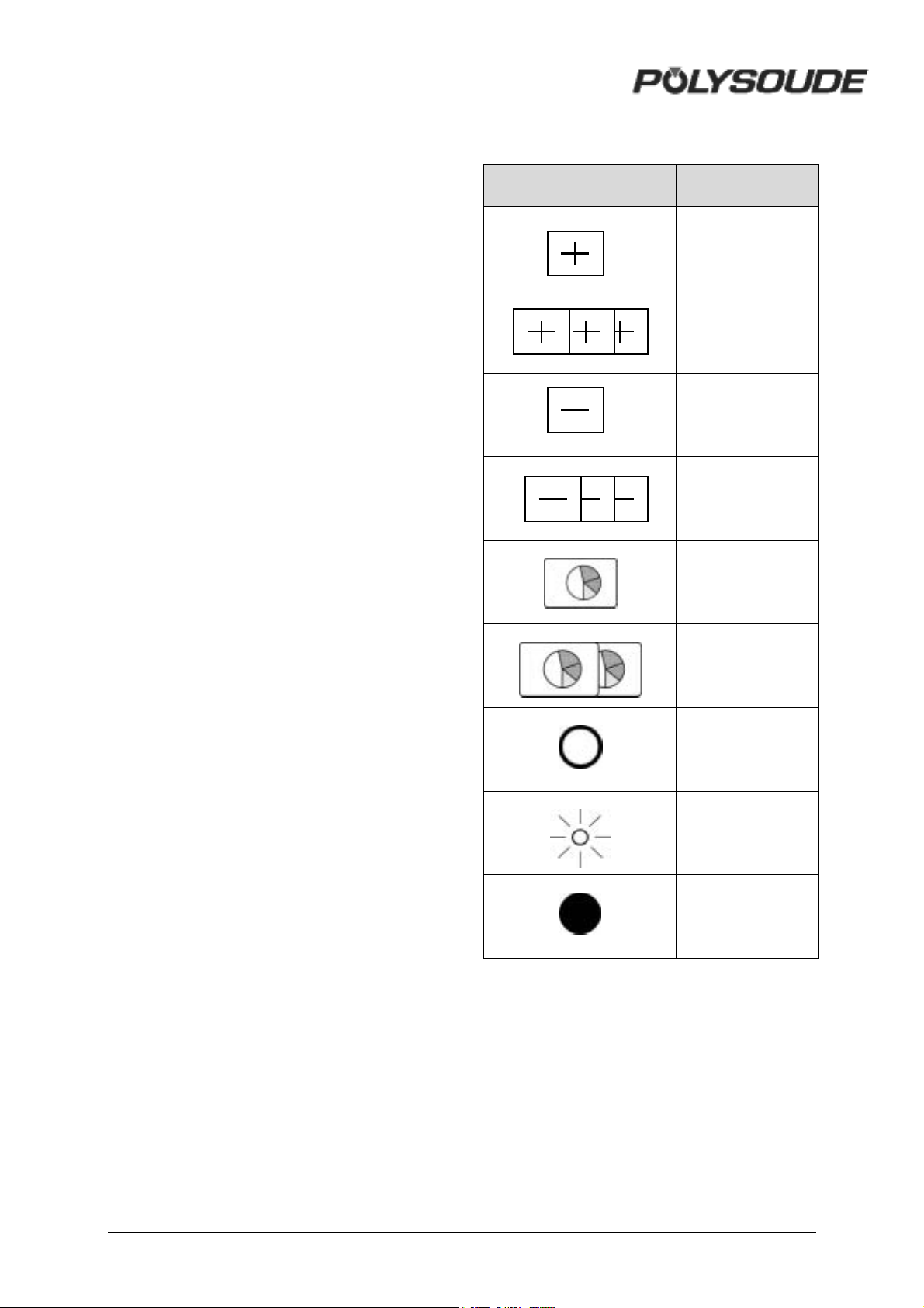
Explanation of symbols used
SYMBOL MEANING
Press once to
increase
Press and hold to
increase
Press once to
decrease
Press and hold to
decrease
Press once
Press and hold for
at least 2 seconds
Indicator not
illuminated
Indicator flashing
Indicator
illuminated
24 MAN. PS 254 EN – Ind. 2
Page 26
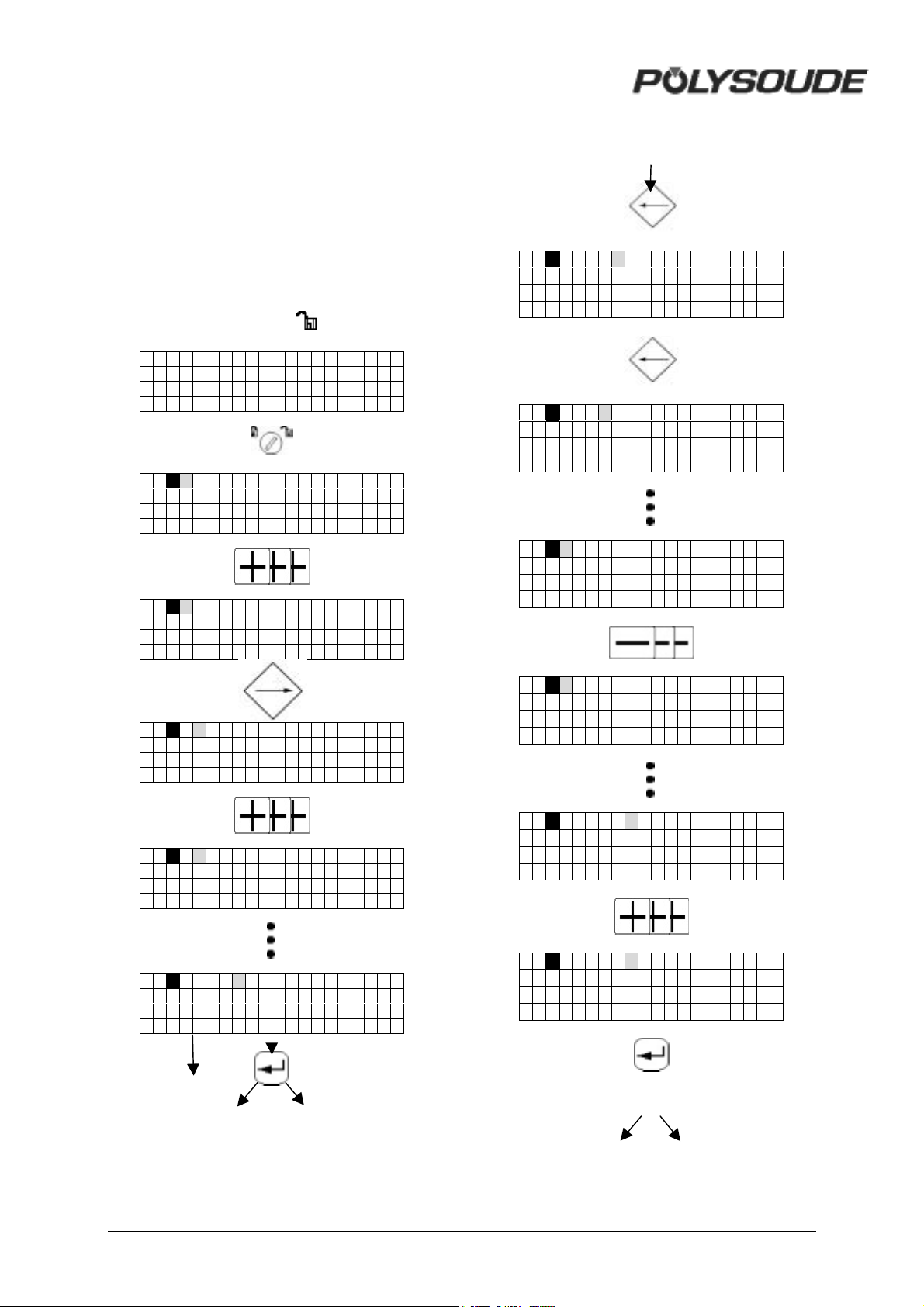
3.3.1. Entering the program name
To choose the number of the program, the
switch of the remote control pendant has to be
used.
The current range (50A/160A) is set with the
key operated switch on the front panel of the
power source.
The key operated switch SY 26 for choosing
the "modification permitted or not" mode of the
machine has to be in the "modification
permitted" position (symbol
POLY SOUDE
PS 2 5 4
01
).
3.3.2. Modifying the program name
#
01 PARI S
01 PARIS
01 PARI S
01 P
01 P
0 1 P A
01 PARI S
01 NAR I S
01 NANTE
01 NANTES
#
$
MAN. PS 254 EN – Ind. 2 25
%
$
%
Page 27
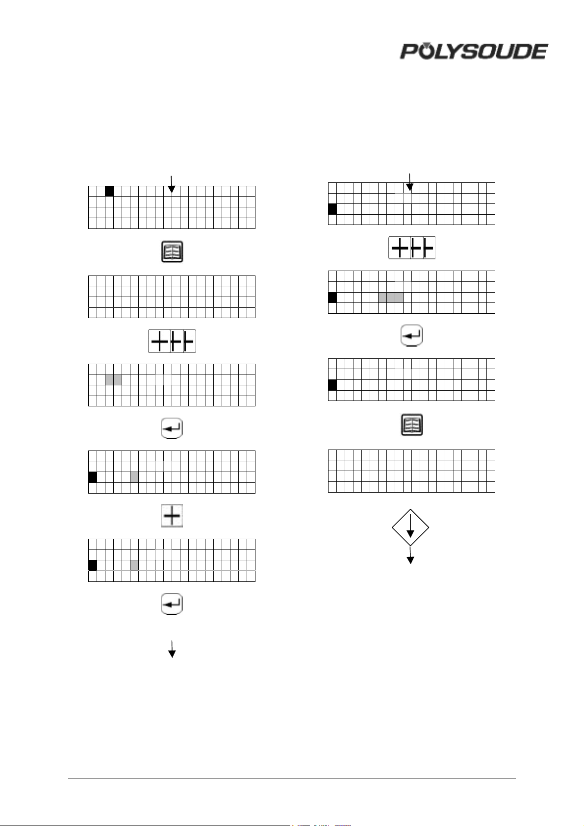
3.3.3. Choice of a built-in program
The choice of a basic program is only possible
after a program name is entered.
After a basic program is chosen, the reference
number of a weld head must be entered to
allow the machine to calculate the travel
speed.
$
01 NANTES
01-NANTES
01 S005 . 0x1 . 0- 0 ?
01-NANTES
1 0S012.7x0.8-0?
01-NANTES
10 S012 . 7x0 . 8- 0
R30=A001
^
&
01-NANTES
10 S012 . 7x0 . 8- 0
R30=B0 0 1
^^^
01-NANTES
10 S012 . 7x0 . 8- 0
R30=B0 0 7
^^^
01-NANTES
10 S012 . 7x0 . 8- 0
R30=B0 0 7
^
01-NANTES
01-NANTES
10 S012 . 7x0 . 8- 0
R30=B001
^
'
&
26 MAN. PS 254 EN – Ind. 2
Page 28
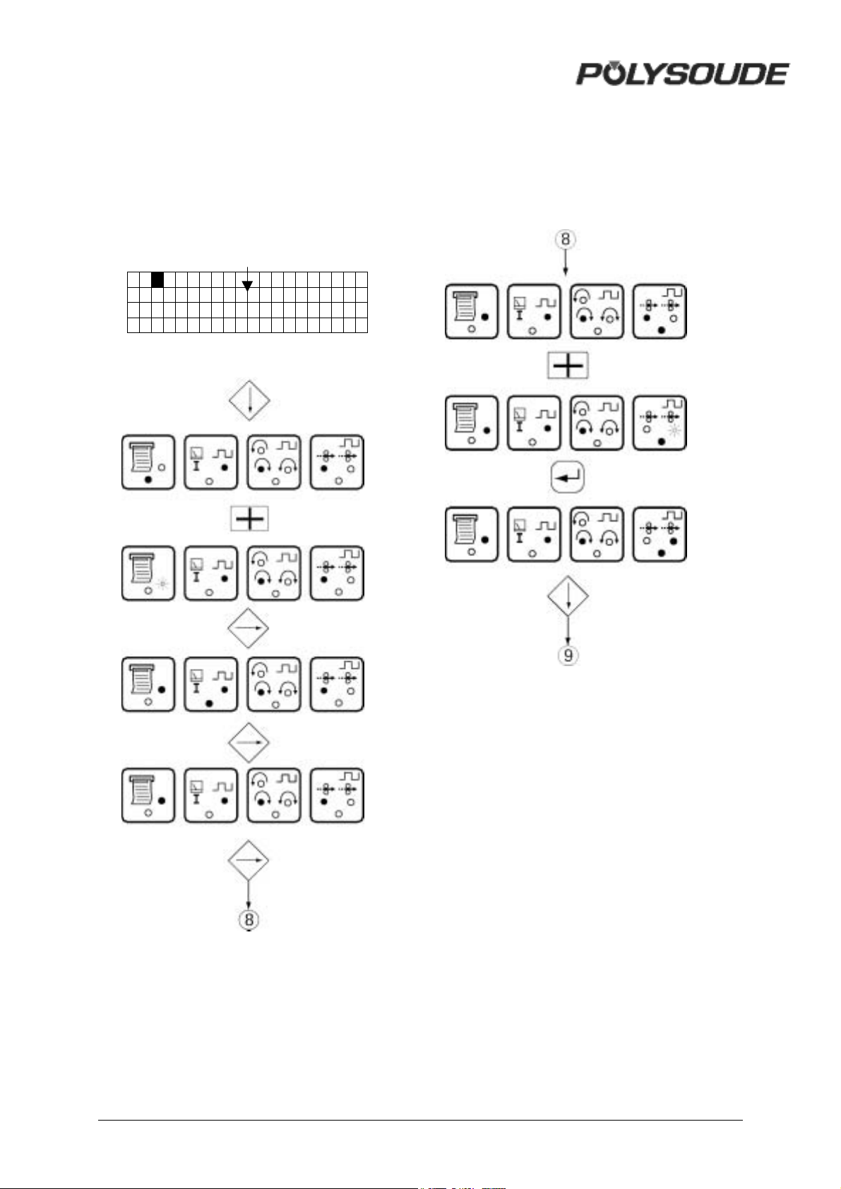
3.3.4. Programming and modifying the
welding parameters
3.3.4.1. Configuration
%
01 NANTES
MAN. PS 254 EN – Ind. 2 27
Page 29
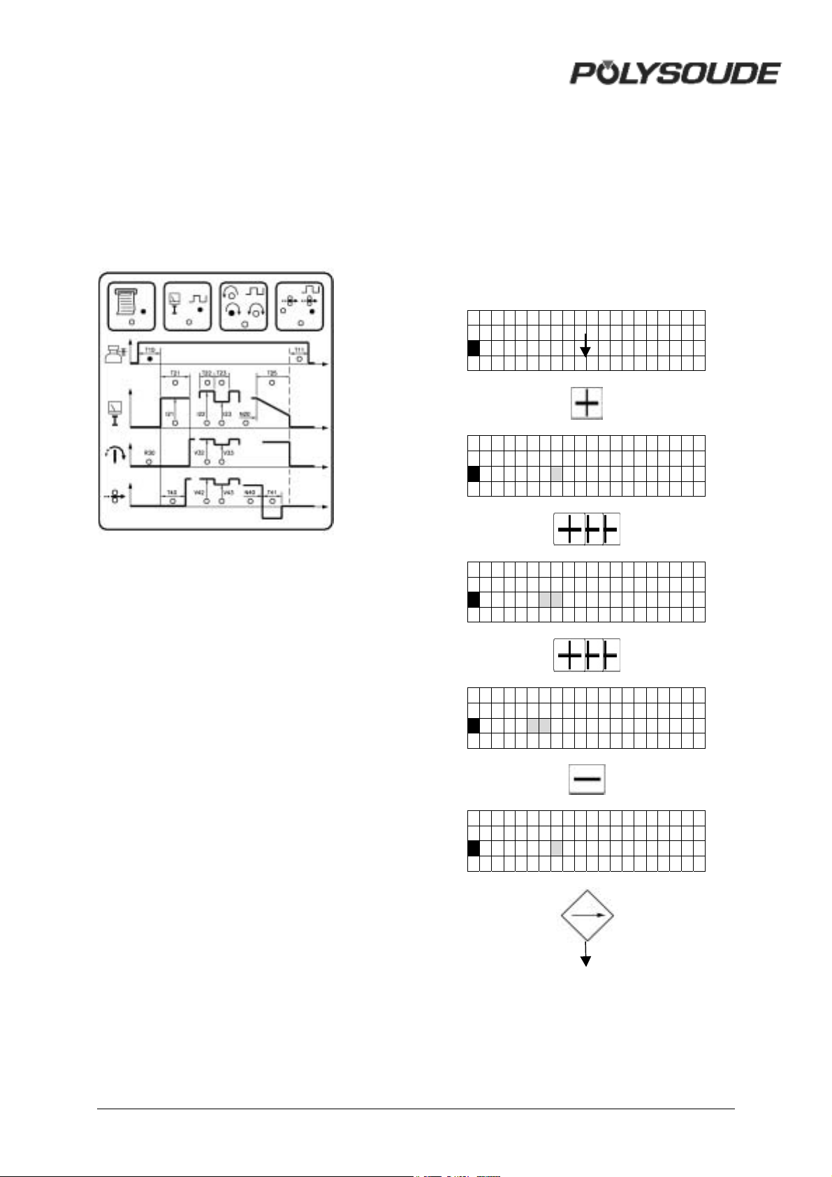
3.3.4.2. Gas
T10 = pregas time
A short press of the key (less than one second)
increases the value of a parameter by one
increment.
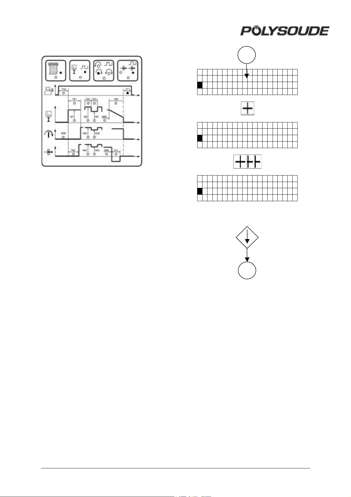
T11 = postgas time
A maintened press of the key increases the
value of a parameter by one increment, then
after one second the value continues to rise
automatically until the key is released. The
value rises by one increment until the value 9
is reached, at which point it begins to rise in
units of ten and afterwards in units of hundred.
'
01- NANTES
T10=005 s
0 1 NANTES
T10=006s
01 NANTES
T10=01 0s
01 NANTES
T10=1 20 s
01 NANTES
T10=119s
(
28 MAN. PS 254 EN – Ind. 2
Page 30
01- NANTES
T11=005 s
01- NANTES
T11=005 s
01- NANTES
T11=005 s
10
11
MAN. PS 254 EN – Ind. 2 29
Page 31
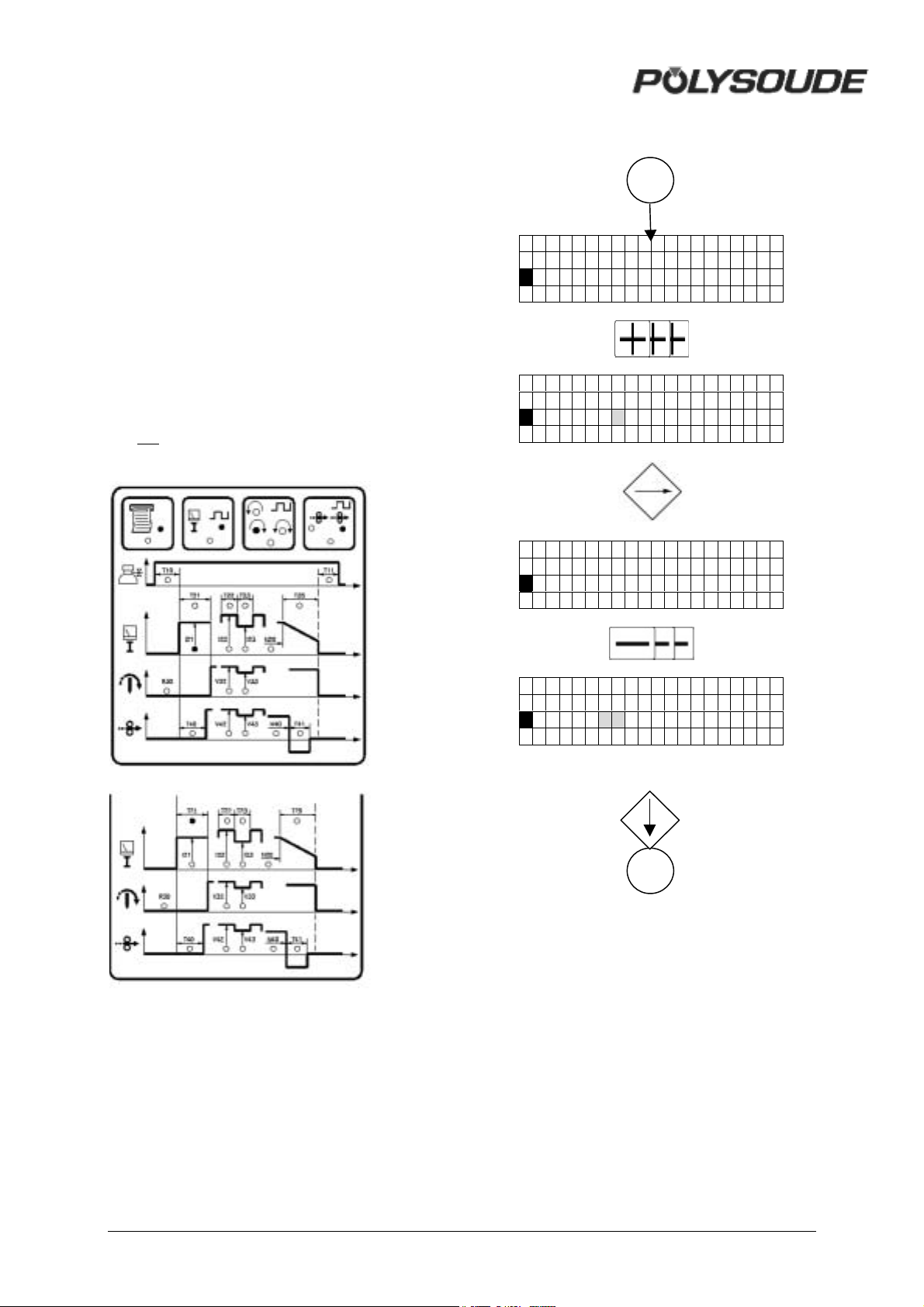
3.3.4.3. Current
! Prefusion
I21 = prefusion current
T21 = time of prefusion current.
A maintened press of the key increases the
value of a parameter by one increment, then
after one second the value continues to rise
automatically until the key is released. The
value rises by one increment until the value 9
is reached, at which point it begins to rise in
units of ten and afterwards in units of hundred.
Prefusion current will be graduate if selected
choice is within configuration.
Prefusion current will be pulsed if selected
choice is within configuration and background
current is within the limits :
I21*I23
I22
11
01- NANTES
I21=090 A
01- NANTES
I21=095A
01- NANTES
T21=03. 0 s
01- NANTES
T21=02 .0 s
12
30 MAN. PS 254 EN – Ind. 2
Page 32
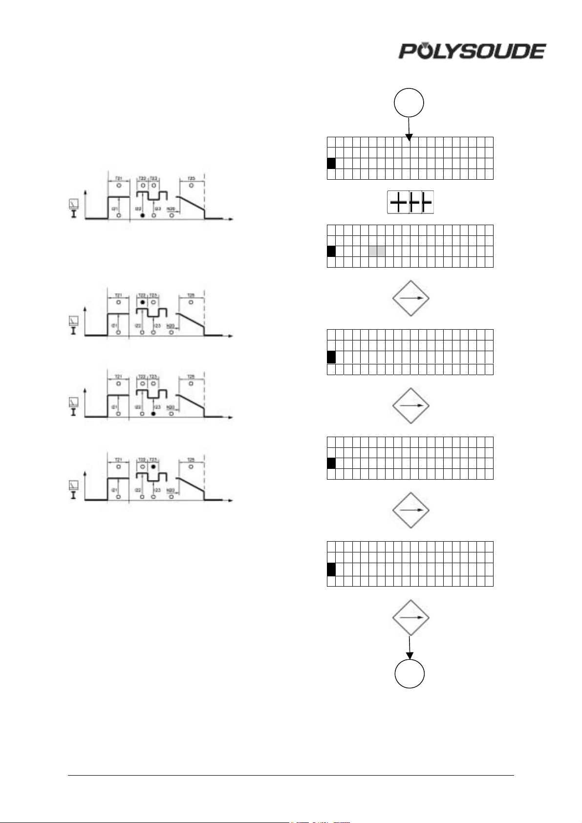
Current
I22 = pulse current
T22 = time of pulse current
I23 = background current
T23 = time of background current
12
01- NANTES
I22=090 A
01- NANTES
I22=1 00 A
01- NANTES
T22=0100 ms
01- NANTES
I23=045 A
01- NANTES
T23=0100 ms
13
MAN. PS 254 EN – Ind. 2 31
Page 33
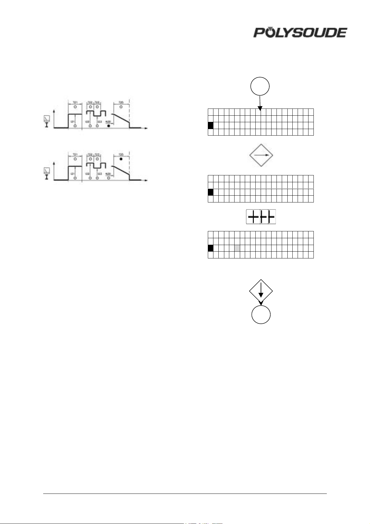
Downslope
N20 = start of downslope
T25 = time of downslope
13
0 1 - NANT ES
N20=0365 D
0 1 - NANT ES
T25=05 s
0 1 NANTES
T25=10 s
14
32 MAN. PS 254 EN – Ind. 2
Page 34
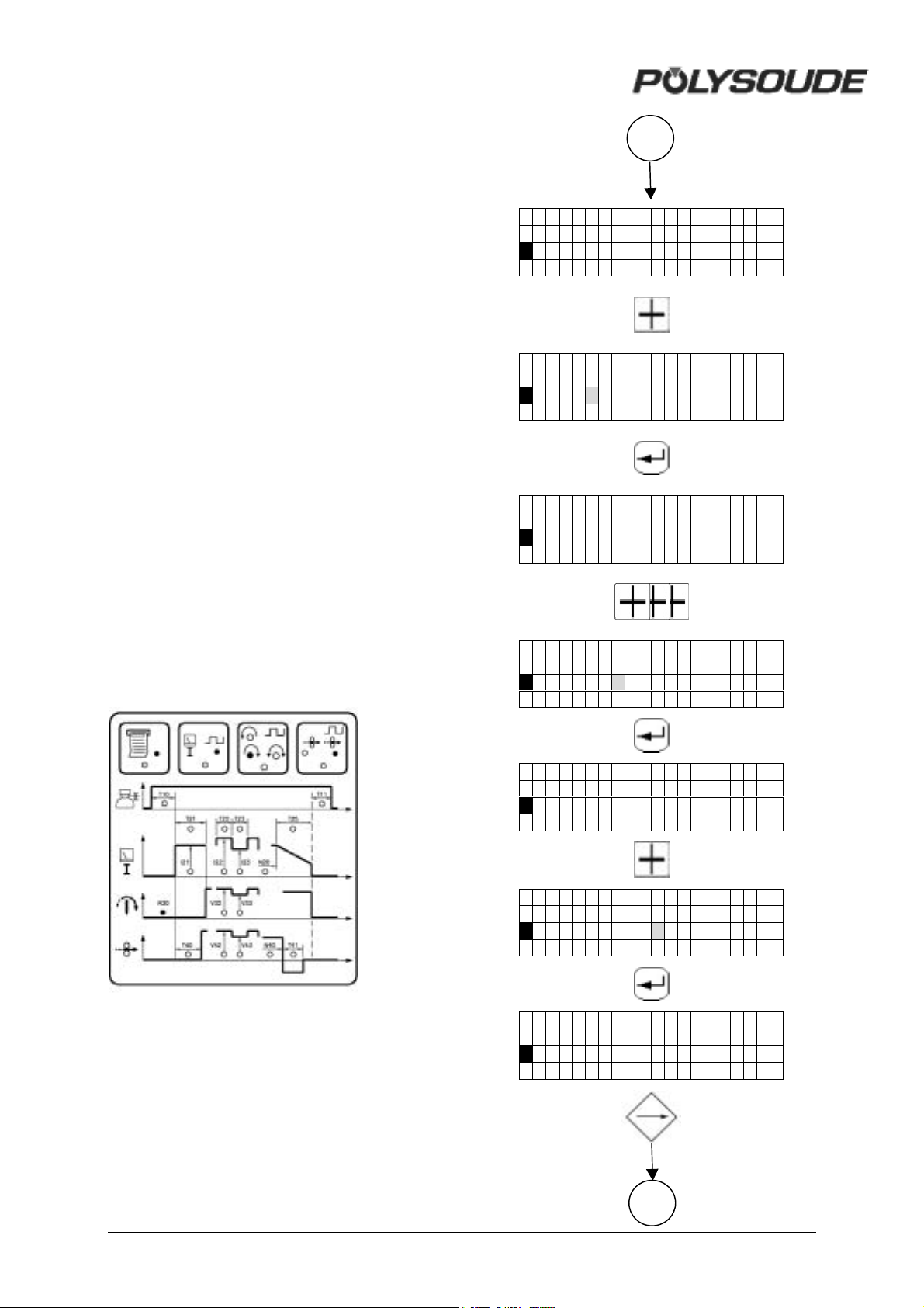
3.3.4.4. Rotation
! Calculation of the value to program to
get a required linear travel speed
The table give a reference number R30 for the
identification of every standard weld head. The
reference number contains a letter and a three
digit number. It has to be correctly introduced
during programming to assure the proper
functioning of the movements.
In order to get a required linear travel speed
VL for a tube diameter D, the value to program
VP (V32 for single travel speed, V33 for step
pulse travel speed) has to be calculated with
the formula:
- VP = C*VL/D
C is a factor due to every type of weld head
and given in the last column of the tables.
Example :
• Weld head MW 65)C = 60 (see table
enclosed welding heads).
• Required linear travel speed VL = 152.5
mm (6 IPM).
• Tube OD D = 25.4 mm (1").
• VP = 60*152,5 mm/min: 25.4 mm (6 IPM:
1").
• VP = 360 = V32..
14
01-NANTES
R30=A001
^
01-NANTES
R30=D001
^
01-NANTES
R30=D001
^ ^^
01-NANTES
R30 = Reference number of the welding head
R30=D034
^^^
R30=D034
^
R30=D034 C
^
R30=D034 C
^
15
MAN. PS 254 EN – Ind. 2 33
Page 35
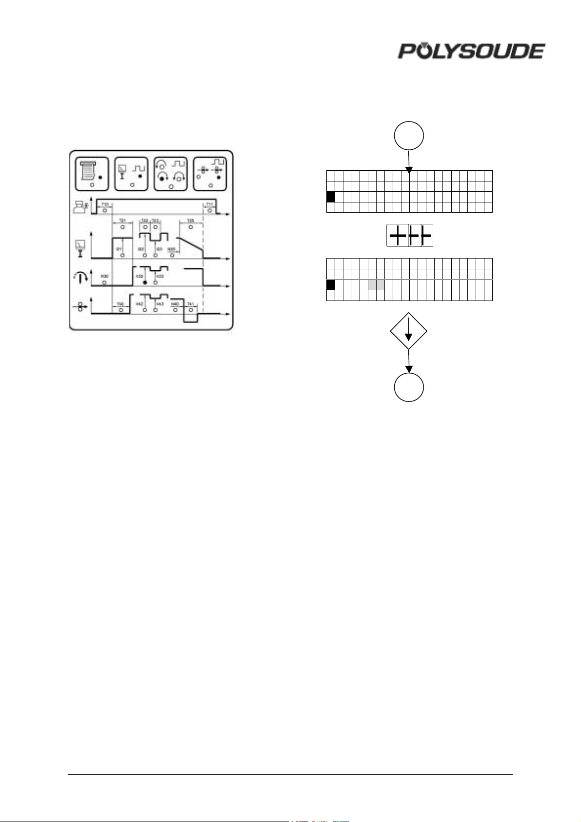
V32 = Smooth welding speed or pendant T22 if
%
%
pulsed rotation
15
01-NANTES
V32=070
01-NANTES
V32=3 60
16
34 MAN. PS 254 EN – Ind. 2
Page 36
! Characteristics of the welding heads
Open welding heads MU III and MU IV
Weld head
type
Minimum
diameter
(mm)
Maximum
diameter
(mm)
Reference
number
(R30)
Number of
impulses per
revolution
Factor C
(VP=C*VL/D)
MU III 16 4 16 A014 357 24
MU III 25 8 26 A028 357 48
MU III 34 20 34 A033 364 58
MU III 8/34 8 34 A033 364 58
MU III 51 25 51 A086 361 150
MU III 20/80 20 80 A073 360 127
MU III 80 32 80 A073 360 127
MU III S 80 32 80 A073 360 127
MU III 114 70 114 A100 360 174
MU III 30/114 30 114 A100 360 174
MU III S 115 17 114 A100 360 174
MU III 170 76 170 A183 359 317
MU III S 170 60 170 A183 359 317
MU III 220 102 220 A322 360 559
MU III 370 150 370 A360 360 625
MU IV 28 8 28 A024 358 41
MU IV 38 8 38 A028 357 48
MU IV 64 14 64 A040 360 69
MU IV 80 19 80 A051 361 89
MU IV 104 19 104 A062 361 108
MU IV 115 10 115 A069 362 120
MU IV 128 25 128 A082 360 142
MU IV 195 76 195 A137 360 238
MU IV 245 101.6 245 A200 360 347
MU IV 275 114 275 A197 360 342
MAN. PS 254 EN – Ind. 2 35
Page 37

Positioners Polyturn
Weld head
type
Minimum
diameter
(mm)
Maximum
diameter
(mm)
Reference
number
(R30)
Number of
impulses per
revolution
Factor C
(VP=C*VL/D)
Polyturn 11 3 180 A017 354 29
Polyturn 50 10 600 A038 356 65
Polyturn 175 35 1000 A132 360 229
36 MAN. PS 254 EN – Ind. 2
Page 38
Closed chamber welding heads with impulse generator
Weld head
type
Minimum
diameter
(mm)
Maximum
diameter
(mm)
Reference
number
(R30)
Number of
impulses per
revolution
Factor C
(VP=C*VL/D)
H 500A 3.17 12.7 B007 366 12
HD 500 P 3.17 12.7 B007 366 12
HD 750 P 4.75 19.05 B009 369 16
HD 1500 P 6 38.1 B015 364 26
K 375 a 1.6 9.5 B009 341 15
K 375 n 1.6 9.5 A016 367 28
K 875 a 3.17 22.2 B010 355 17
K 875 n 3.17 22.2 A018 367 32
K 1500 6.35 38.1 B025 362 44
K 2000 12.7 50.8 B025 356 43
K 2500 12.7 63.5 B028 360 49
K 3000 25.4 76.2 B031 363 54
K 4000 38.1 101.6 B038 359 66
K 6000-T 50.8 152.4 A110 362 190
K 7000 76.2 177.8 A200 360 347
MW40 6 40 D023 C 360 40
MW65 10 65 D034 C 365 60
MW115 10 115 D073 C 358 126
MW170 10 170 C103 C 359 178
MW1250 6 33.4 C017 369 30
MW2500 9.5 63.5 C047 358 81
MW4500 25 114.3 A119 359 206
UHP 250 1.6 6.35 D006 384 11
UHP 500 3.0 12.7 D009 360 16
UHP 1500 6.0 38.1 D023 360 40
* a : previous
n : new
MAN. PS 254 EN – Ind. 2 37
Page 39
Tachometer controlled closed chamber welding heads
Weld head
type
Minimum
diameter
(mm)
Maximum
diameter
(mm)
Reference
number
(R30)
Number of
impulses per
revolution
Factor C
(VP=C*VL/D)
K 375 1/16 3/8 G018 367 32
K 875 1/8 7/8 G018 367 32
K 875 (option) 1/8 7/8 G009 367 16
K 1500 1/4 1/12 G018 367 32
K 2000 1/2 2 F037 357 64
K 2500 1/2 2 1/2 F037 357 64
K 300 1 3 F037 357 64
K 4000 1 1/2 4 F037 357 64
K 6000 2 6 G183 361 318
K 7000 3 7 G183 361 318
H 500 1/8 1/2 G018 367 32
H 750 1/8 1/4 G018 367 32
H 1500 3/16 1 1/2 G018 367 32
MW 1250 1/8 1 5/16 G018 367 32
MW 2500 1/2 2 1/2 F037 357 64
MW 4500 2 4 1/2 F073 362 127
UHP 250 A 1/16 1/4 G006 367 11
UHP 500 A 1/8 1/2 G009 367 16
UHP 1500 A 1/2 1 1/2 G018 367 32
38 MAN. PS 254 EN – Ind. 2
Page 40
Welding heads TS-TP for tube to tubesheet
welding
Reference number R30 :
• Axxx * Welding heads without switch to
detect the home position.
• Hxxx * Welding heads with switch to
return to the home position after the end of
the weld cycle, using the shortest way.
• Jxxx * Welding heads return to the home
position after the end of the weld cycle, in
the opposite direction of the welding.
Weld head
type
TS 25 6 25
TS 73 8,5 60
TS – TP 60 8,5 60
TS 2000 10 60
Minimum
diameter
(mm)
Maximum
diameter
(mm)
Reference
number
(R30)
A014
(H014, J014)
A044
(H044, J014)
A044
(H044, J014)
A032
(H032, J032)
Number of
impulses per
revolution
359 24
364 77
364 77
357 55
SCK 20 20 C021 365 37
Factor C
(VP=C*VL/D)
MAN. PS 254 EN – Ind. 2 39
Page 41

Tachometer controlled closed chamber
welding heads
Control of an external speed variator
It is possible to adjust the rotation speed of
closed chamber welding heads with
tachometer. Find out the code of the reference
R30 for the closed chamber welding head in
the table hereabove. Enter this reference code
into the power source and validate. To start
one revolution of the head, push the sector key
SY 14. The rotation speed can be calculated
by the time the weld head needs for one
revolution.
Welding heads with home position switch
If the measured speed is included in a range of
9 % of the theorical speed, the speed will be
automatically adjusted during weld cycles. If
the speed difference is more than ± 9 %, an
arrow * or + will appear on the sceen to
indicate the correction to be applied on the
welding head.
• In the case of an arrow * showing to the
right, increase the rotation speed by
turning the potentiometer inside the
welding head clockwise.
• In the case of an arrow + showing to the
left, decrease the rotation speed by turning
the potentiometer in the welding head
counterclockwise.
• Push the sector key SY 15 again and
repeat adjustments, if necessary, until no
arrow will appear on the screen. The
speed difference is now less than ± 9 %
and corrections will be made
automatically.
Welding heads without home position
switch
After a push on the sector key SY 15, the
welding head should do a whole revolution.
If not the speed must be adjusted by turning
the potentiometer inside the weldhead:
It is possible to control an external speed
variator. There are two possibilities to program
the reference number R30:
• For a time base of 1/10 seconds the letter
I followed by 0,1 s has to be introduced
(R30 = I0,1s).
• For a time base of seconds the letter I
followed by 1 s has to be introduced (R30
= I1s).
The weld cycle is now controlled by time (1/10
seconds or seconds) and not by the position of
the welding head (impulse control). The
internal clock of the power source is
generating the impulse signals.
To command the external speed variator, an
interface (signal generation for start and
direction of rotation) has to be connected to
the rotation plug FA 3 of the power source.
Control of the power source by prise
manual welding head
• Use of a manual torch
R30=yyyy
, Working cycle without movements and
pulsing
, Downslope
, End of cycle
• Use of a welding head
♦ R30=yyyy C (MW40, MW65, MW115 and
MW170)
, Forward rotation of the head
, Test gas and cooling agent
, Working cycle without considering the
open position of the weld head but with the
head going back to the open position at
the end of the cycle
, Downslope
, End of cycle
• If the rotation of the welding head is less
than one revolution, its speed must be
increased by turning the potentiometer
clockwise.
• If the rotation of the welding head is more
than one revolution, its speed must be
decreased by turning the potentiometer
counterclockwise.
Push the sector key SY 15 again and repeat
adjustments, if necessary, until the rotation
stops exactly after one revolution.
40 MAN. PS 254 EN – Ind. 2
♦ R30=yyyy X (other heads)
, Forward rotatio the head
, Test gas and cooling agent
, Working cycle considering the open
position of the head and with the head
going back to the open position at the end
of the cycle
, Downslope
, End of cycle
Page 42
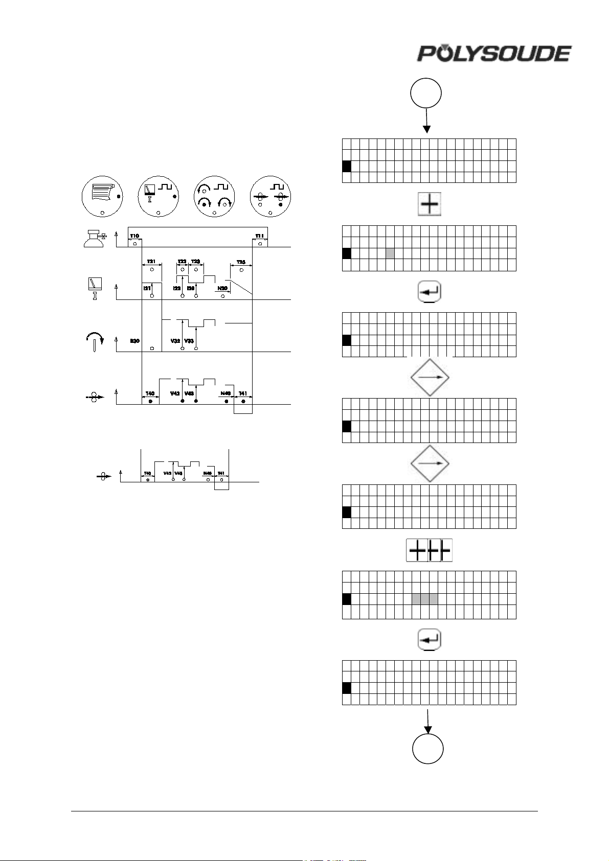
3.3.4.5. Wire
‰
‰
‰
R40 = Selection of wire feeder
A = Polyfil B
B = Polyfil
T40 = Wire start
V42 = Wire speed with unpulsed wire feeding
or wire speed during pulse current period
16
01-NANTES
R4 0=A
01-NANTES
R4 0=B
01-NANTES
R4 0=B
01-NANTES
T4 0=003 s
01-NANTES
S1 V4 2=200
01-NANTES
S1 V4 2=4 0 0
01-NANTES
S1 V4 2=400
17
MAN. PS 254 EN – Ind. 2 41
Page 43
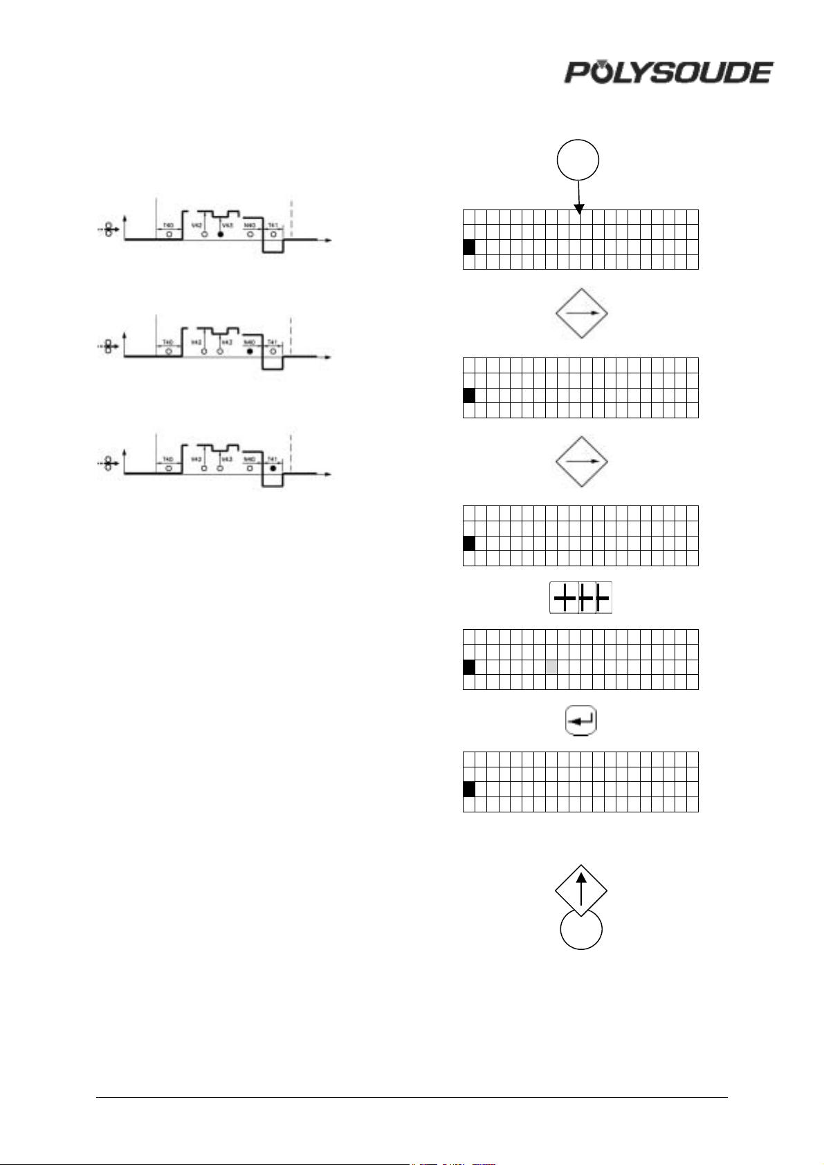
V43 = Wire speed during background current
‰
period.
N40 = Wire stop.
T41 = Wire retract.
17
01-NANTES
S1V4 3=050
01-NANTES
N40=360 D
01-NANTES
T41=2.0 s
01-NANTES
T41=2.5s
01-NANTES
T41=2.5 s
18
42 MAN. PS 254 EN – Ind. 2
Page 44
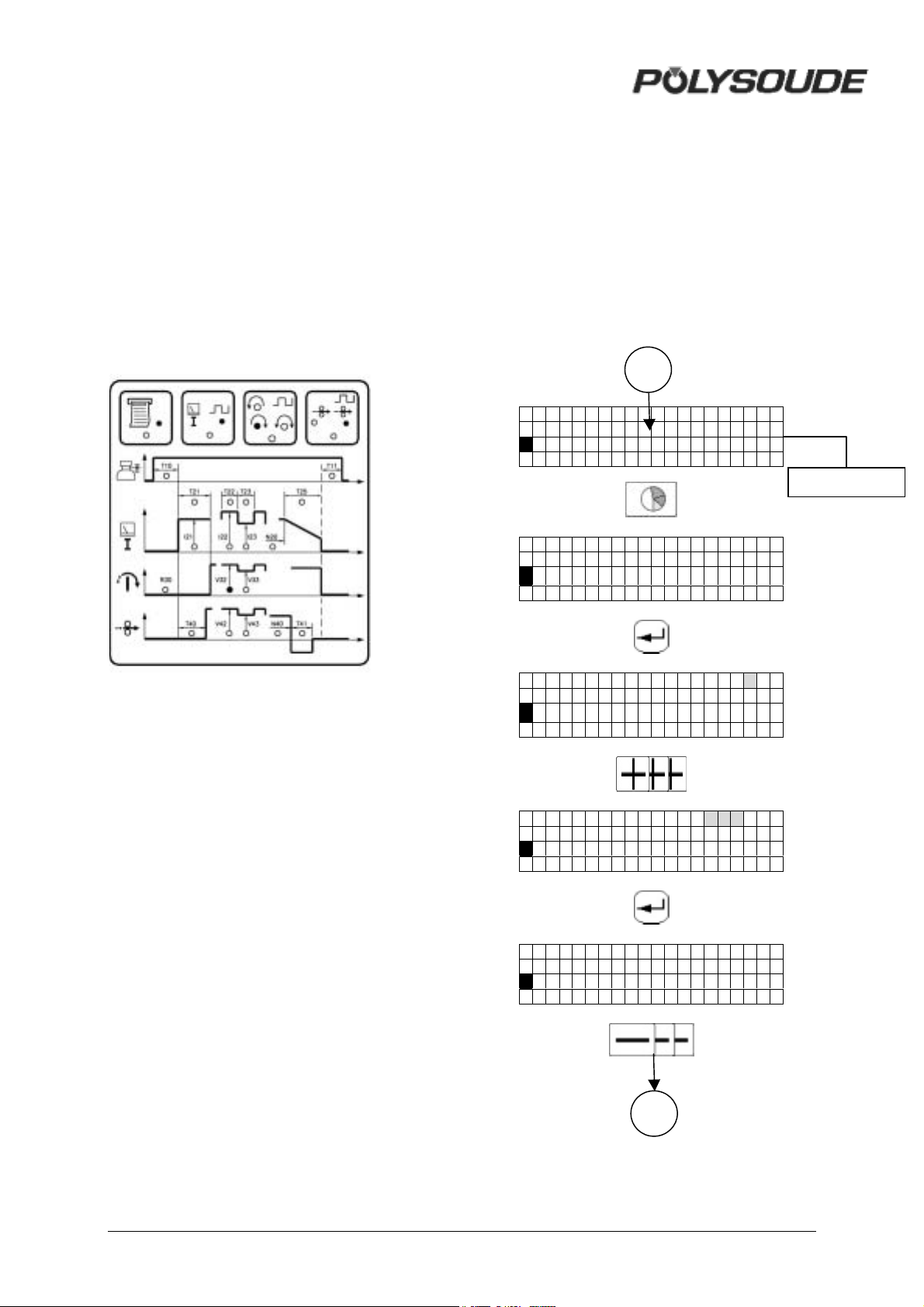
3.3.5. Programming of sectors
‰
‰
‰
‰
‰
‰
‰
‰
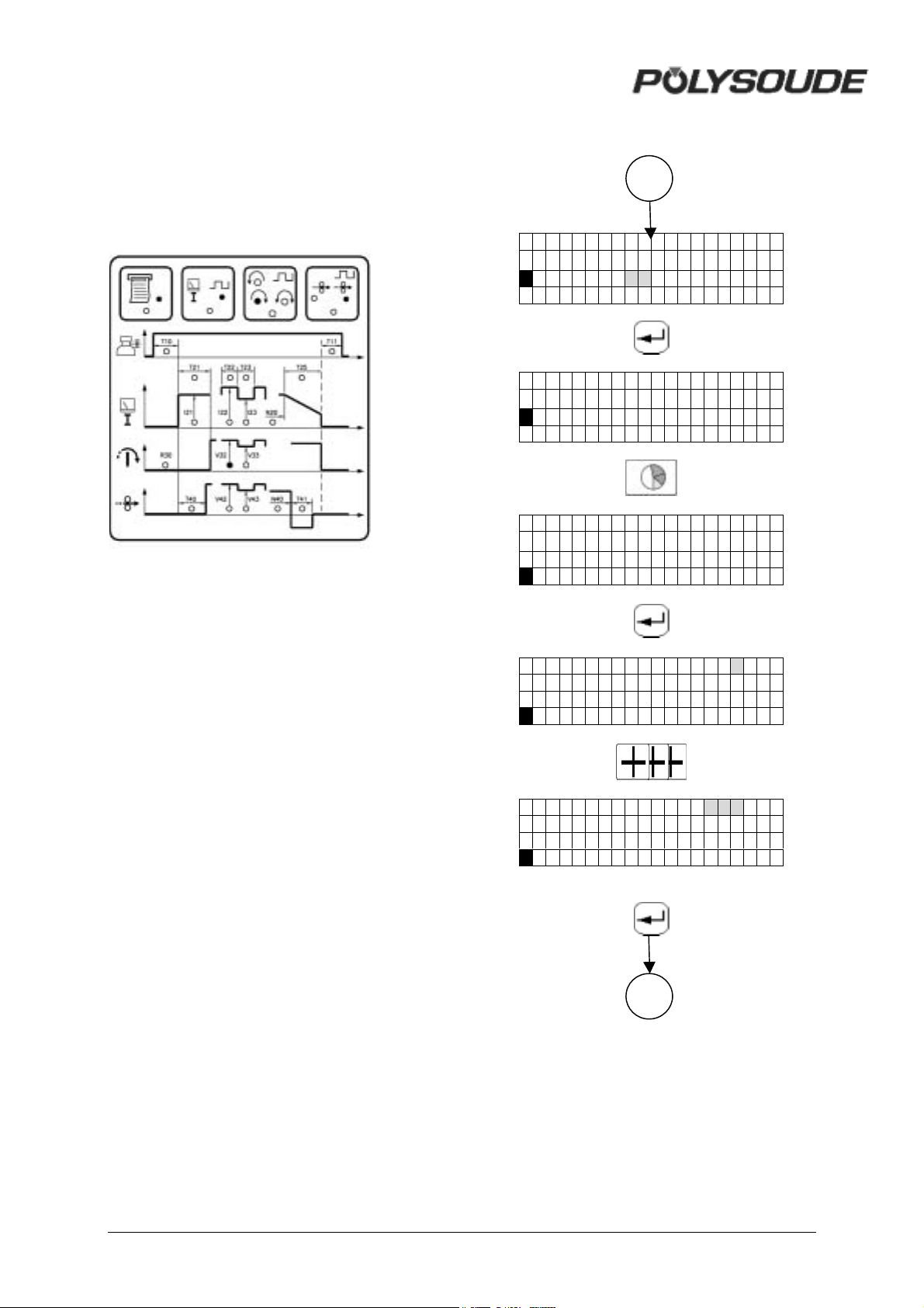
3.3.5.1. Creation of a sector
A sector is characterized by its number (S) and
the value (N) indicating the sector start
position.
If a sector is created, the actual values of the
weld parameters are automatically transfered
(that's why the programming of a sector should
be completely finished before the next one is
created).
The value of the parameter "N" for the actual
sector must be higher than the value of the
preceeding sector and lower than the value
"N30" (start of the downslope). If this is not the
case, the value will not be accepted.
18
01-NANTES
V32=2 00
Other
01-NANTES
S1 V3 2=200
S2?
01-NANTES N=0001D
S1 V32=200
S2 V3 2=200
01-NANTES N=0 1 00 D
S1 V32=200
S2 V3 2=200
01-NANTES N=0100 D
S1 V32=200
S2 V3 2=200
18
MAN. PS 254 EN – Ind. 2 43
Page 45
‰
‰
‰
‰
‰
‰
‰
‰
‰
‰
‰
‰
18
01-NANTES N=0100 D
S1 V32=200
S2 V3 2=1 80
01-NANTES N=0100 D
S1 V32=200
S2 V3 2=180
01-NANTES N=0100 D
S1 V32=200
S2 V3 2=180
S3 ?
01-NANTES N=0100 D
S1 V32=200
S2 V3 2=180
S3 V3 2=180
01-NANTES N=0 1 50 D
S1 V32=200
S2 V3 2=180
S3 V3 2=180
19
44 MAN. PS 254 EN – Ind. 2
Page 46
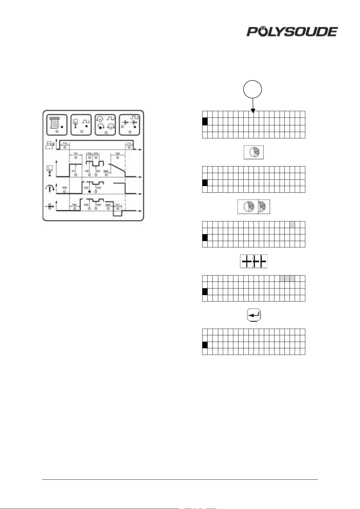
3.3.5.2. Modification of sector start
‰
‰
‰
‰
‰
‰
‰
‰
‰
‰
‰
‰
‰
‰
‰
position
During modification, the value of parameter "N"
must be between the values of the preceeding
and the following sector. If this is not the case,
the value will not be accepted.
19
01-NANTES
S1 V32=200
S2 V3 2=180
S3 V32=180
01-NANTES N=0100 D
S1 V32=200
S2 V3 2=180
S3 V3 2=180
01-NANTES N=0100D
S1 V32=200
S2 V3 2=180
S3 V3 2=180
01-NANTES N=01 3 0D
S1 V32=200
S2 V3 2=180
S3 V3 2=180
01-NANTES N=0130 D
S1 V32=200
S2 V3 2=180
S3 V3 2=180
MAN. PS 254 EN – Ind. 2 45
Page 47
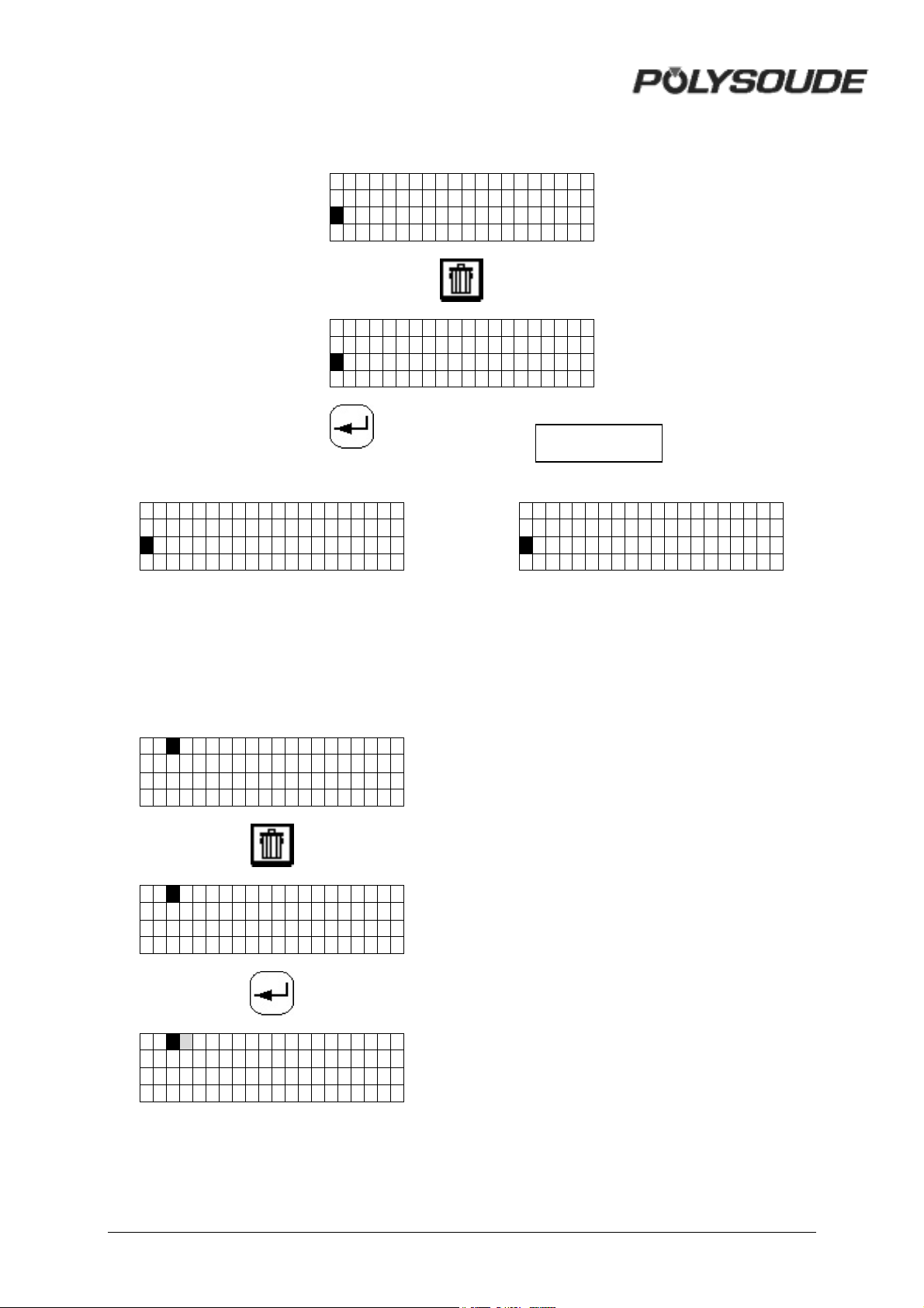
3.3.5.3. Deleting a sector
C1 - NANTES N=0 1 3 0 D
S1 I 22=100 A
S2I22=105 A
S3 I 22=120 A
01-NANTES N=0130 D
S1 I 22=100 A
S2I22=105 A?
S3 I 22=120 A
Other button
01-NANTES N=0150 D
S1 I 22=100 A
S2I22=120 A
S3 I 22=125 A
3.3.6. Deleting a program from the
source memory
To select the program to be deleted, enter the
program number with the remote control
pendant.
00 PARI S
00 PARI S ?
01 NANTES N=0130 D
S1 I 22=100 A
S2I22=105 A
S3 I 22=120 A
00
POLYSOUDE
PS 2 5 4
46 MAN. PS 254 EN – Ind. 2
Page 48
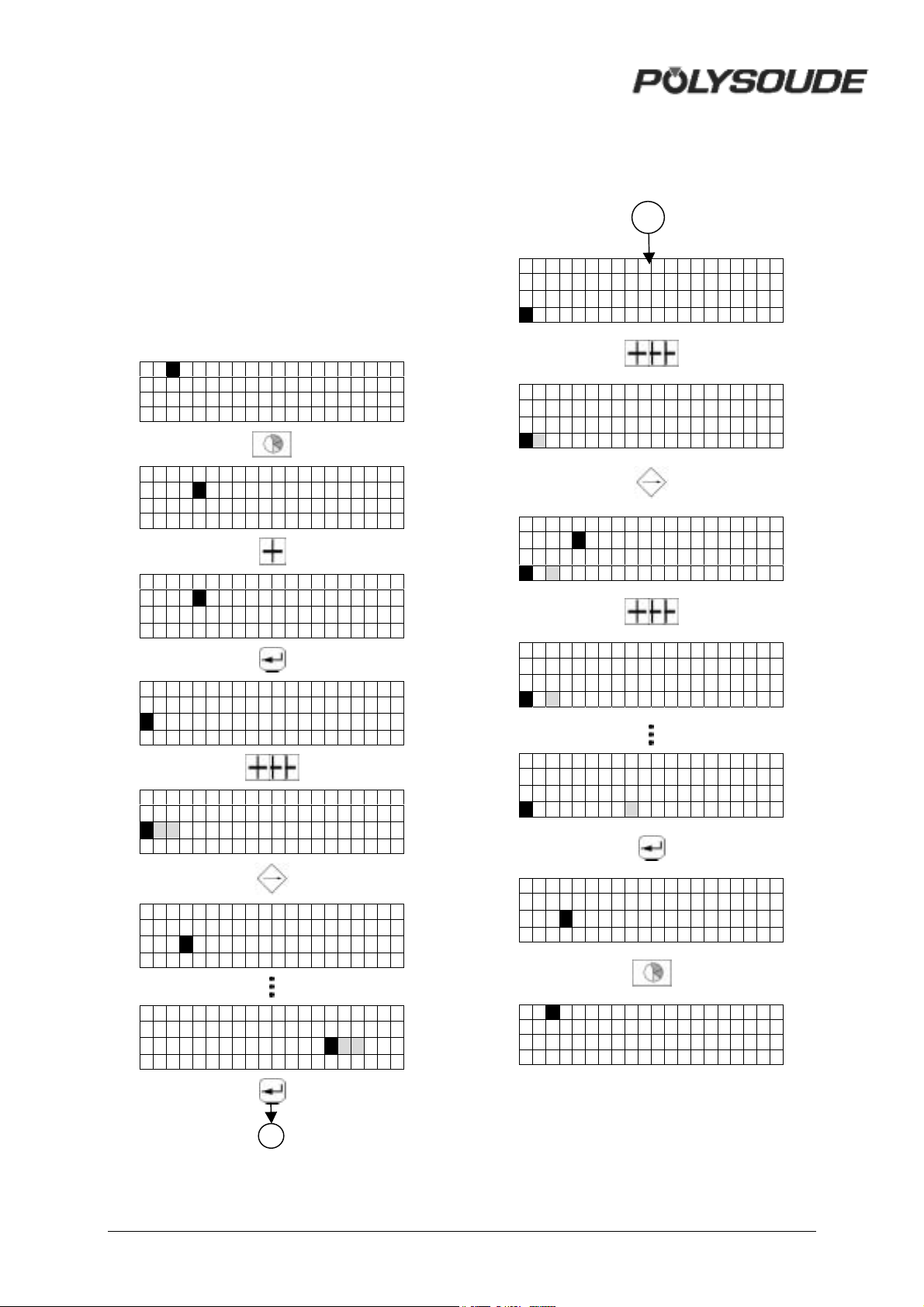
3.3.7. Entering the time and date
With the key switch in the open position, and
when creating or modifying the name of a
program, you can also access the mode for
entering or modifying the time, the date and
the company name by pressing the "sector"
key.
By pressing the "enter" key you can change
between the displays for the time, the date and
the company name. You can exit this mode by
pressing the "sector" key.
01 NANTES
PS 254
0->24H
20: 30 : 20 04- 08 - 96
PS 254
0->12H
08: 30 : 20pm 08 - 04- 96
3.3.8. Entering / modifiying the company
name
27
PS 254
0->12H
10: 31 : 20pm 08 - 24- 96
PS 254
0->12H
10: 31 : 20pm 08 - 25- 96
C
PS 254
0->12H
10: 31 : 20pm 08 - 25- 96
C U
PS 254
0->12H
08: 30 : 20pm 08 - 04- 96
PS 254
0->12H
1 0 : 30 : 20pm 08 - 04- 96
c PS 254
0->12H
10 30 : 2 0 pm 0 8 - 0 4 - 9 6
PS 254
0->12H
10: 31 : 20pm 08 2 5 -96
PS 254
0->12H
10: 31 : 20pm 08 - 25- 96
C U
PS 254
0->12H
10: 31 : 20pm 08 - 25- 96
CUSTOMER
PS 254
0->12H
10 31 : 2 0 pm 0 8 - 2 5 - 9 6
CUSTOMER
01 NANTES
27
MAN. PS 254 EN – Ind. 2 47
Page 49

3.3.9. Saving, loading a program
! Saving a program on a memo card
Each program can be saved on a memo card,
16 programs per card is possible. The
procedure is described in the programming
manual. A brief summary is given below.
2 possibilities :
* Saving a single program
• Check that the key switch SY 26 is in the
position "Modification authorised".
• Insert the memo card.
• Choose the number of the program to be
saved with the switch BT 4 on the remote
control pendant.
• Press the transfer button to save the
information on the memo card
(symbol ).
• If the name of the program to be saved
already exists on the memo card, the
name of this program is displayed with a
question mark.
• If you validate the saving with the button
SY 23, the program which has been stored
on the memo card will be replaced by the
new one. The indicator corresponding to
the saving function will illuminate. Wait for
the indicator to extinguish before removing
the memo card.
• If the memo card is full, the error code !77
! is shown on the display SY 25.
* Saving several programs
• Check that the key switch SY 26 is in the
position "Modification authorised".
• Insert the memo card.
• Press the transfer button to save the
information on the memo card
(symbol ).
• Press the button « plus » (symbol ),
the characters 0 -> 15 ? are shown on the
display. The button «minus »
(symbol ) enables to come back to the
loading function of a single program.
• If you validate the saving with the button
SY 23, all the programs which are in the
memory of the power source
will be saved and the indicator corresponding
to the saving will illuminate. Wait for the
indicator to extinguish before removing the
memo card.
If, during the transfer, a fault is detected, the
operation is stopped and an error code is
shown on the display of the PS 254. Refer to
Appendix 3 and Chapter 8.5 for the error
codes and corrections to be made.
The program name is stored on the memo card
together with the program. However, the
number under which it is stored in the PS 254
is not saved. You can load the program under
a new number or in another power source. A
label on each card allows you to write manually
any information which you deem to be useful.
! Loading a program from a memo card
To load a program from a memo card, the
procedure is as follows:
*2 possibilities :
* Loading of a single program
• Insert the memo card.
• Choose the number you wish to give to the
program with the switch BT 4 on the
remote control pendant. This number
cannot already be attributed to another
program, but can correspond to a program
that you wish to replace.
• Press the button to load a program from
the memo card (symbol ).
• The first program stored on the memo
card is indicated on the display SY25.
• The keys SY 17 and SY 19 are used to
scroll up or down the programs.
• Validate the transfer by pressing . The
corresponding indicator will illuminate.
• Wait for the indicator to extinguish before
removing the card.
Warning If the program that is
registered in the card is not
compatible with the SY 30
selected range of current, it
will not be loaded up and !75!
error code is displayed on
the screen.
48 MAN. PS 254 EN – Ind. 2
Page 50
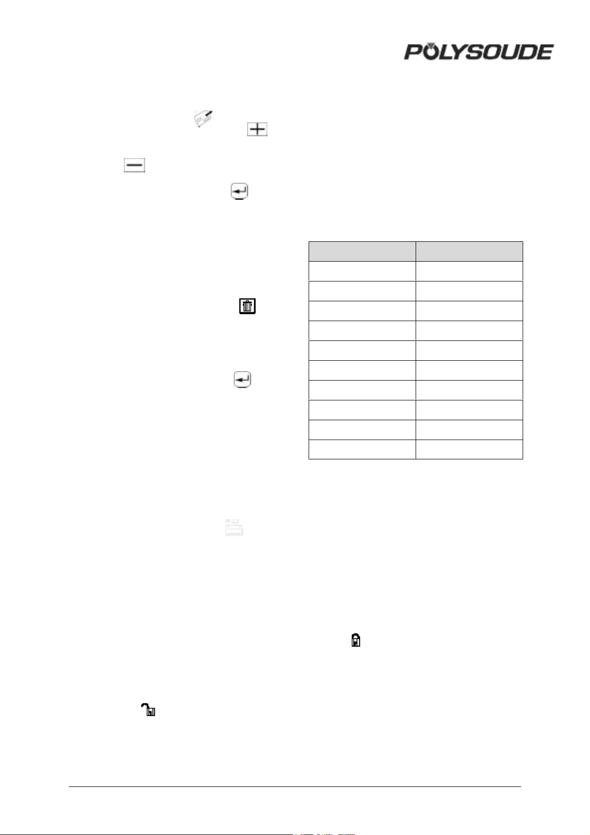
* Loading of all the programs
• Insert the memo card.
• Press the button to load a program from
the memo card (symbol ).
• Press the button « plus » (symbol ),
the characters 0 -> 15 ? are shown on the
display. The button « minus »
(symbol ) enables to come back to the
loading function of a single program.
• Validate by pressing the button . The
corresponding indicator will illuminate.
• Wait for the indicator to extinguish before
removing the memo card.
pulsed speed rotation) or V42 parameters with
the "Delta" buttons.
The modification values of the delta buttons
cannot be changed by the user. It depends on
the value of the parameter which is being
acted upon. The table below gives the
relationship between the parameter value and
the correction made by each press of the delta
button.
When a delta button is used, the value of the
parameter concerned is displayed during 5
seconds on the front face of the PS 254.
Wire feeder rotation speed :
! Deleting a program from the memo card
• Check that the key switch SY 26 is in the
position « Modification authorised ».
• Insert the memo card.
• Press the button « trash » (symbol ), the
name of the first program stored on the
memo card is shown on the display.
• The keys SY 17 and SY 19 are used to
scroll up and down the program you wish
to delete.
• Validate the transfer by pressing . The
corresponding indicator will illuminate.
• You can cancel the suppression of a
programme by pressing again the button
« trash ».
3.3.10. Printing a program
To print a program from a memo card, the
procedure is as follows:
• With the switch BT 4 on the remote control
pendant, choose the number of the
program to print.
• Press the print button (symbol ).
• Validate. The printing indicator is
illuminated.
• After the printing is finished, this indicator
will extinguish.
• Modifications of the values of weld
parameters can be done in two different
modes, one during development of a weld
procedure and the second in production.
! Modifying the parameters before
starting a program
To select this mode, turn the key operated
switch SY 26 to the "Modification authorised"
position (symbol ). The key can be removed
afterwards.
In this mode you can increase (+) or decrease
(-) during the weld cycle the values of the I22,
V32 (for no-pulsed speed rotation), V33 (for
Value of parameter Delta
<= 99
1
100 - 199 2
200 – 299 3
300 – 399 4
400 – 499 5
500 – 599 6
600 – 699 7
700 – 799 8
800 – 899 9
900 – 999 10
All actions on the delta buttons are taken into
account (within the parameter limits) and
stored in the memory of the relevant sector.
After moving from one sector to another, the
corrections made in the preceding one are
carried through to the next. The modifications
are not forgotten or lost. The number of deltas
in this mode is not limited.
! Modifications made during the weld
cycle
To access the production mode, the key
operated switch SY 26 has to be turned to the
"Program modification not authorised" position
(symbol ). The key can be removed
afterwards to avoid unauthorised modifications
being made to the programs.
This mode includes two differences:
• The number of deltas per parameter is
limited to 10 (10 increments or 10
decrements)
• The modifications are not stored in the
memory.
MAN. PS 254 EN – Ind. 2 49
Page 51

For program version L633 5.0 onwards, if
the last character (the eigth) of the program
name consists of a dollar symbol ($), no
modification of the welding parameters by
the remote control pendant is possible.
! Fault detecting during cycle
During every welding cycle, important
parameter values are monitored periodically at
different delicate points. When a fault is
detected, an immediate stop or a stop with
downslope is initiated depending on the
seriousness of the fault. The fault is indicated
by a flashing light on the remote control
pendant. An error code will also appear on the
display of the PS 254. Appendix 5.2 gives the
error codes, their meaning and their
consequences. We advise you to take careful
notice as to which error code is shown. This
can make maintenance or repair work easier
and highly efficient.
3.3.11. Programmable parameters
For each parameter, the following table shows:
• The synoptic reference (Ref.).
• The corresponding name.
• The maximum value programmable.
• The minimum value programmable.
• The increment value that will be added or
taken away when the buttons « + » or « - »
are pressed on the synoptic.
• The default value proposed during the
creation of a new program.
• The units used. In each column, the
abbreviations stand for:
A Amperage.
V Voltage.
D Movement.
/M A thousandth of the maximum value.
s A second.
ms A millisecond.
50 MAN. PS 254 EN – Ind. 2
Page 52
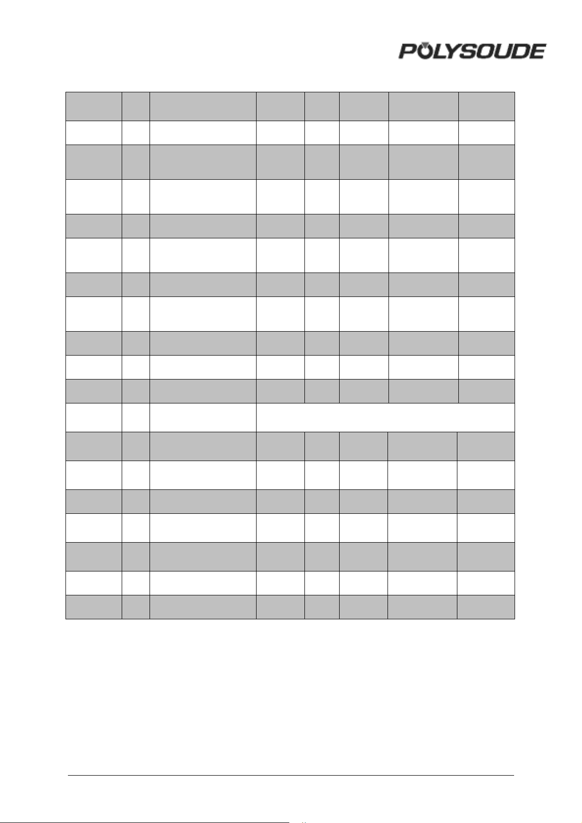
REF DESIGNATION MAX. MIN. OUTPUT INCREMENT
DEFAULT
VALUE
Gas
Current
Rotation
T10 Pre-gas time 320 1 s 1 5
T11 Post-gas time 320 1 s 1
I21 Prefusion current
T21 Prefusion time 30 0,1 S 0,1 3
I22 Pulse current
T22 Pulse time 9999 10 Ms 1 100
I23 Background current
T23 Background time 9999 10 Ms 1 100
N20 Downslope 9999 1 D 1 365
T25 Downslope time 60 1 S 1 5
R30
Welding head
reference
200
2A 1 90
100
200
2A 1 90
100
200
2A 1 45
100
See pages 35 to 39
10
15
Wire
V32 Rotation speed (high) 999
V33 Rotation speed (base) 999
T40 Delay for wire start 40 0 S 1 3
V42 Wire feed speed (high) 999
V43
N40 Wire stop 9999 1 D 1 360
T41 Delay for wire retract 9,9 0 S 0,1 2
Wire feed speed
(base)
999
50
then 0
50
then 0
50
then 0
50
then 0
/M 1 70
/M 1 50
/M 1 200
/M 1 200
MAN. PS 254 EN – Ind. 2 51
Page 53
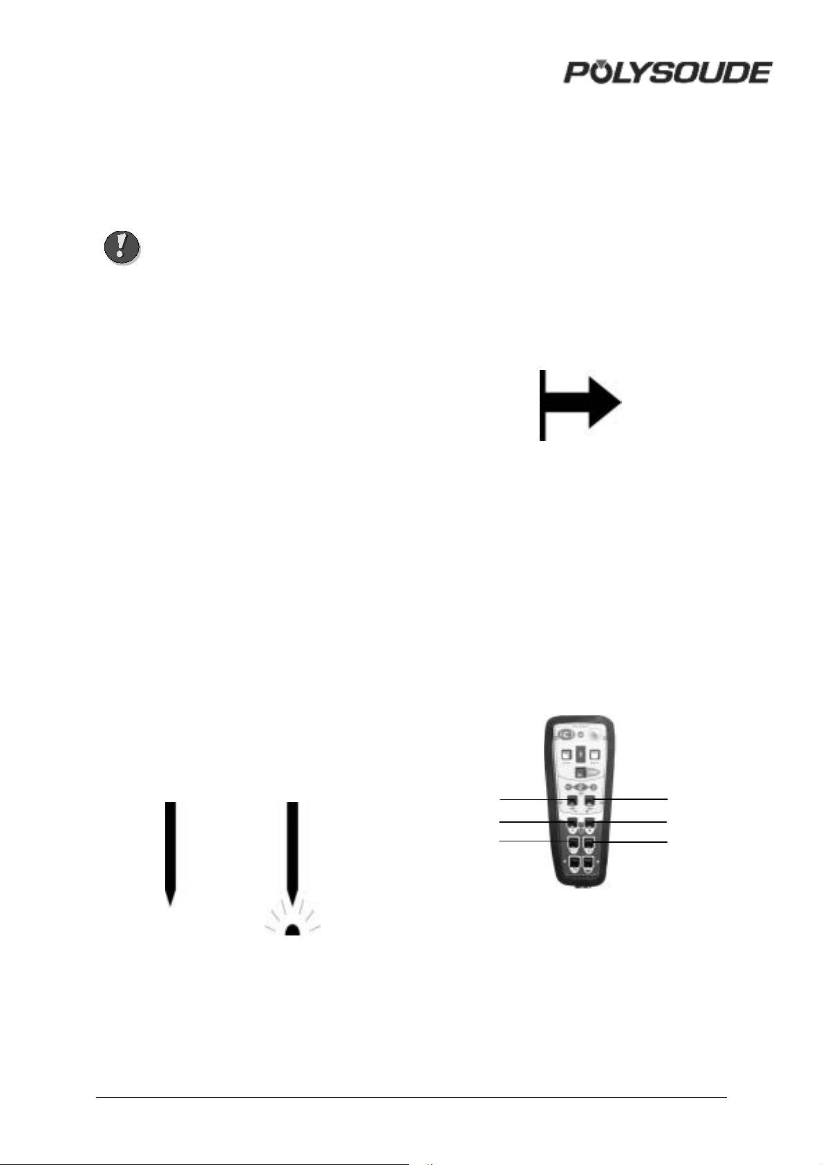
3.4. Execution of a weld program
3.4.1. Safety precautions
Warning Before starting any
manipulation on the
equipment please refer to
chapter 1.2 "Safety
precautions".
3.4.2. Choosing the program to be
executed
The program to be executed is selected with
the switch BT 4 on the remote control pendant.
You can check the name of the program on the
display of the PS 254. If only "POLYSOUDE
PS 254" appears, you have selected the
number of a user program place where nothing
is stored in the memory of the PS 254. If !75! is
displayed on the screen, the right range of
current is not selected.
3.4.3. Simulation
After the correct program has been
selected, you can run a simulation without
affecting the workpiece to be welded. In
this case, all the functions of the selected
program are carried out except those
concerning the arc and the coolant circuit.
The gas controls are executed but the flow
rates are not considered. So it is possible to
check flow adjustment or reduce gas
consumption during the simulation.
The choice between a simulated or a real weld
cycle is made with the switch BT 1 on the
remote control pendant.
3.4.4. Weld cycle
! Starting the weld cycle
The weld cycle is initiated by pressing the
button BT 5 on the remote control pendant.
The indicator BT 3 becomes illuminated when
the cycle starts. If for the selected number a
program does not exist in the memory of the
PS 254, no cycle will be started and the
indicator will flash. The flashing can be turned
off by pressing any button on the remote
control pendant.
Fig. 3.7 : "Start cycle" button
! Modification of a weld cycle
Parameter values can be modified during the
weld cycle with the remote control pendant.
The values of the modifiable parameters in
each sector are:
• The current or maximum current in the
case of pulsed current (I22).
• The rotation speed (V32) or low rotation
speed in case of pulsed rotation (V33).
• The wire speed or the high wire speed in
the case of pulsed wire (V42).
BT 14
BT 9
BT 11
BT 13
BT
BT 10
8
Fig. 3.8 : "Delta" buttons for
modifications of parameter values
Fig. 3.6 : "Set up / weld" selector switch
52 MAN. PS 254 EN – Ind. 2
Page 54
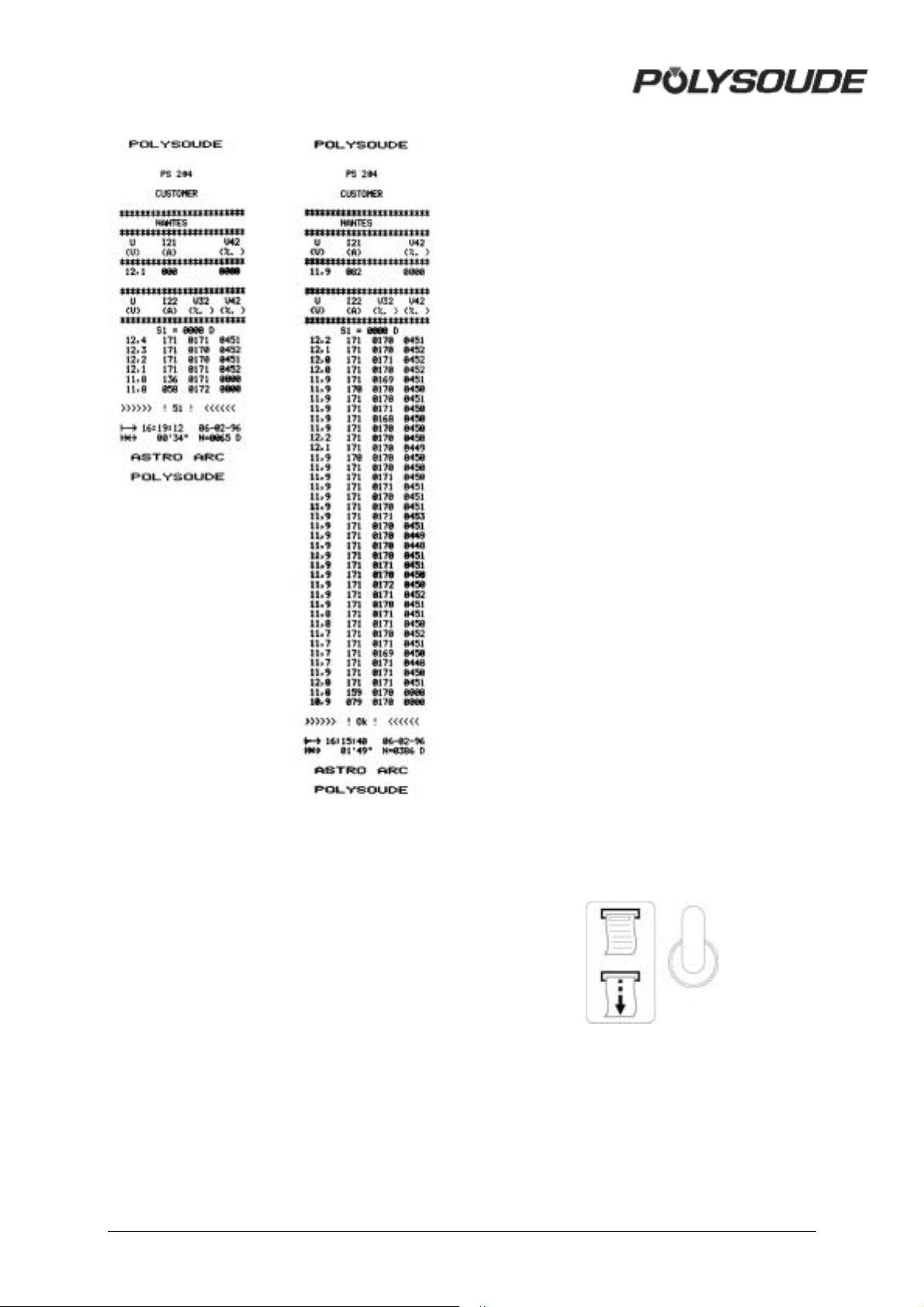
3.4.5. End of welding cycle
! Normal end of welding cycle
In the case of a normal end of the welding
cycle, the indicator on the remote control
pendant extinguishes. The power source is
now ready to start a new cycle.
N.B.: welding head that is fitted out with an
"open head" position sensor will be
automatically positioned in this way at the
regular end of a cycle.
! Weld cycle report
At the end of every weld, you can print a weld
cycle report indicating periodically the real
values of the main weld parameters. This
listing is provided automatically if
preprogrammed. After a weld cycle in
simulation mode, no weld report can be given.
The weld cycle report consists of:
• The name of your company.
• The program name.
• Values of periodically taken
measurements of the voltage, amperage,
rotation speed and wire speed during the
cycle.
• Reason for stop ("OK" for a normal cycle
end, if not, error code).
• Time of cycle start.
• Date of weld.
• Length of cycle.
• Tungsten location.
! Reprint of a weld cycle report
Fig. 3.9 Fig. 3.10
If the printout of a weld cycle report fails, for
example because of a lack of paper, it is
possible to restart it by pushing the switch SY
29 situated at the right of the printer upwards.
Fig. 3.9 : Example of a weld cycle report
with manual downslope, denoted by error
code >>>> ! 52 ! <<<<
Fig. 3.10 : Example of a weld cycle report
with a normal cycle end, denoted by
>>>> ! OK ! <<<<
Fig. 3.11 : Printer switch
3.4.6. Manual weld cycle stop
! Manual weld cycle stop with downslope
The manual downslope button BT 6 on the
remote control pendant starts the programmed
MAN. PS 254 EN – Ind. 2 53
Page 55

downslope sequence. This function provides
the workpiece as much as possible from being
damaged. The indicator will flash because this
is not a regular cycle end.
Fig. 3.12 : Manual downslope button
! Immediate cycle stop
When the stop button BT 7 of the remote
control pendant is pressed, the arc and all
movements are stopped immediately. The
shielding gas is maintained during the
programmed post gas period T25. The
indicator will flash because this is not a regular
cycle end.
The arc is struck by pressing the manual
command button. The weld current value is
equal to the programmed ignition current. If
you release this button, the high current value
I22 is applied. If you press this button again,
the low current I23 will be used. The next
release restarts the high current and so on.
The cycle stop is made either by pressing on
the downslope button, or for an immediate
cycle stop, by pressing on both ends of the
manual command button.
Fig. 3.13 : Immediate manual stop button
! Emergency stop
The remote control pendant is fitted with an
emergency button BT 2. By pressing this
button, the PS 254 is immediately
disconnected from the mains power supply.
The weld, the movements and the gas flow are
stopped suddenly.
This function may cause serious damages to
the workpiece and equipment. Polysoude
advises you, if possible, to choose a stop
with the downslope button or with the
immediate stop button.
Fig. 3.14 : Emergency stop button
! Using a manual welding torch
You should introduce a short program with
both a high and a low current when welding
with a manual torch as described in paragraph
2.3.6.
54 MAN. PS 254 EN – Ind. 2
Page 56

4. SERVICING, MAINTENANCE AND TROUBLESHOOTING
4.1. Servicing
4.1.1. Adjustments
! General
The expression calibration is defined by
regulating standards and is used when the
generator has to meet special requirements,
for example Quality Assurance or ISO 9000
quality system. Calibration needs specific
testing equipment and procedures: we can
perform it on special request, in your company
or in our workshop.
Following informations concern routine
adjustment that you can perform, outside these
cases, as frequently as you think it advisable,
for example as it is said further.
! Necessary equipment
To be able to make adjustments, it is
recommanded to have at your disposal:
• A voltmeter.
• A shunt or any other means of measuring
continuous current of a current at least
equal to 200 A and of the class 0.2.
• A TIG (GTAW) welding torch of a sufficient
capacity.
• A resistance of 2 Ω/200 W.
! How to adjust?
Before carrying out a regulation check, leave
the generator switched on for approximately 15
minutes. This will allow the generator to reach
its normal working temperature. If this is not
done, the adjustments that you make will be
altered because of the rise in temperature
during a normal cycle. To access the cards,
remove the front panel of the generator. It will
also be necessary to bypass the short circuit
security of the inverter unit. To do this, put the
switch S3/2 of the 21700633 card and the
switch S1/4 of the 21700634 synoptic card to
the CLOSED position.
Warning After the adjustments have
been made put the switches
to the "OPEN" position,
otherwise the short circuit
security system of the
generator will not work
properly.
! When to adjust?
A drift may occur with time ; it results from
ageing of components. So we recommend you
to check power source adjustments on an
average of one year.
! Exchange of cards or the inverter unit
The 21700633 sequencer card and the
21700634 synoptic card are pre-adjusted in
the factory. In case of a standard exchange of
these cards, no further adjustments are
necessary. However, further adjustments are
necessary in case of replacement of the
21700690 card or the source.
MAN. PS 254 EN – Ind. 2 55
Page 57
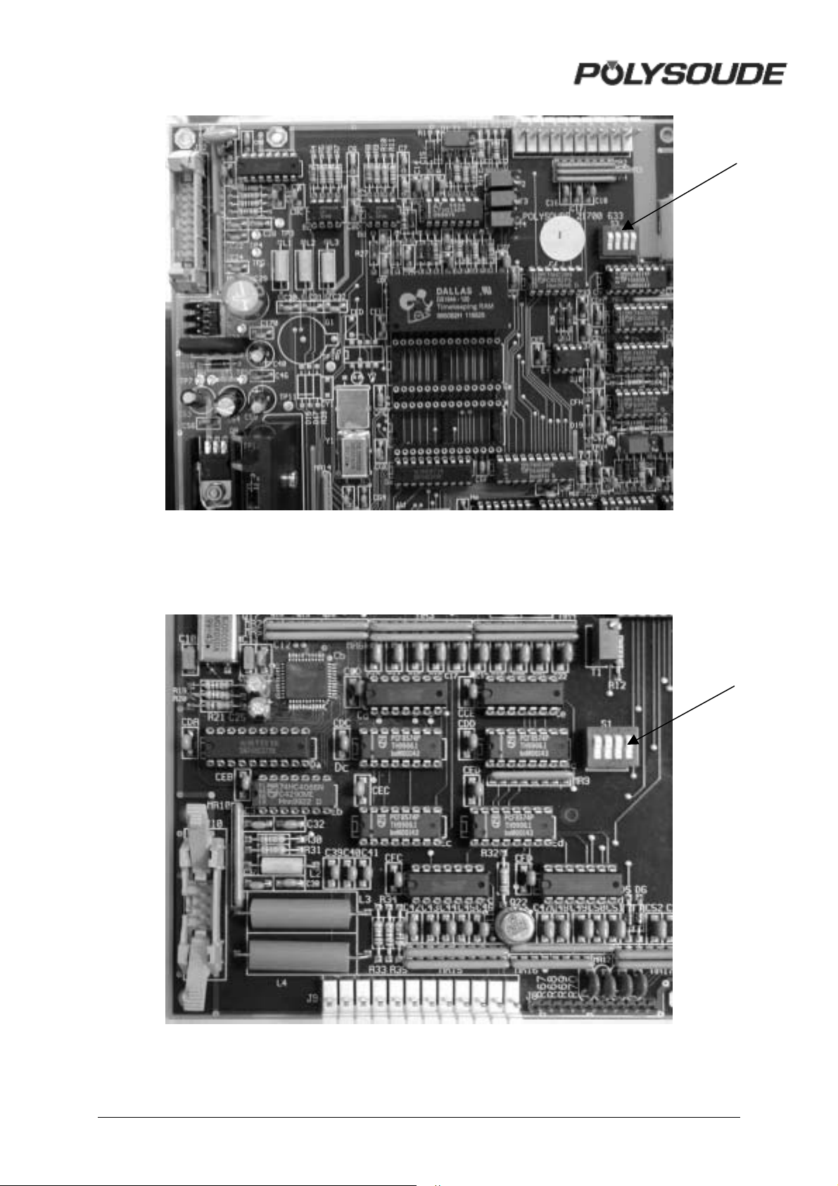
F ig. 4.1 : Inverter switch S3/2 for shunt circuit security system of monitoring welding current
in « CLOSED » position for adjustments (sequencer card)
S32
Fig 4.2 : Inverter switch S1/4 in « CLOSED » position (21700634 synoptic card)
S14
56 MAN. PS 254 EN – Ind. 2
Page 58
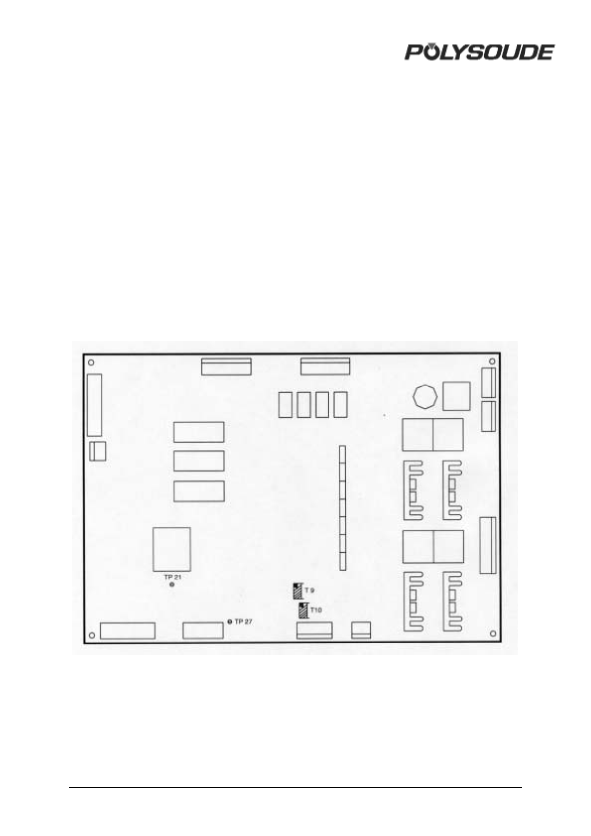
4.1.2. Adjustment of the inverter unit
! Verification of the current reference
signal
The current reference signal is generated on
the sequencer card (217 00 633). The signal is
adjusted in the factory, for readjustment please
contact the Polysoude after-sales service.
A Move the key-operated switch on the
programming board at the front side
to the 160 A position.
B Connect a voltmeter between TP21 0
V analog and the test point TP27.
C Introduce a program without
pulsation with a current of 160 A.
D Start a weld cycle with the switch
"Set up/Weld" in the "Set up"
position. The voltage read must be
10 V. If not, use the potentiometer
T9.
E Start a new cycle with a current
programmed at 4 A. Now the voltage
read must be 0,25 V. If not, use the
potentiometer T10.
F Repeat operations D and E until the
set-up is correct.
Fig. 4.3 : Potentiometers and test points for the regulation of the current reference on the
21700633 sequencer card
MAN. PS 254 EN – Ind. 2 57
Page 59
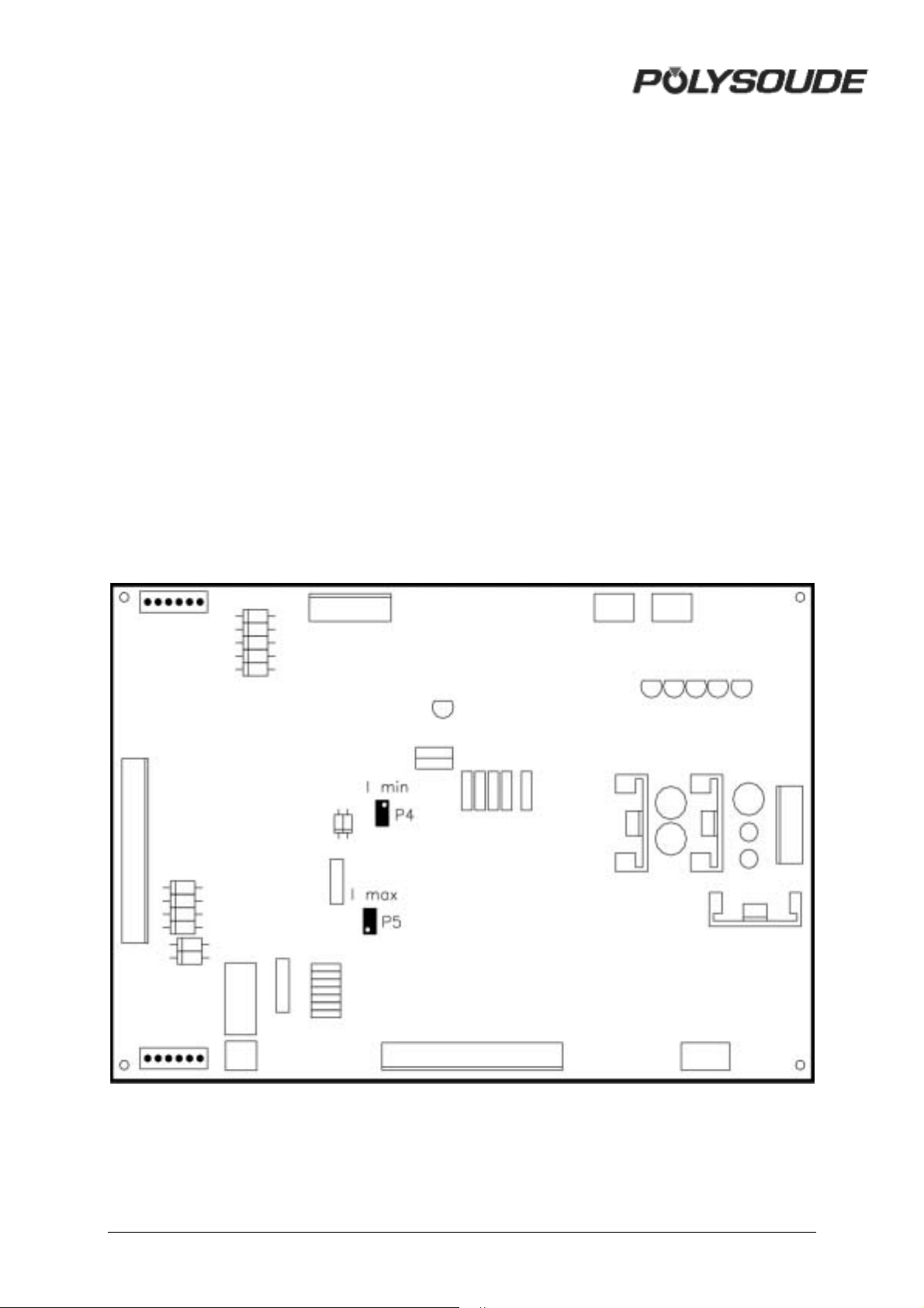
! Regulation of the current
As long as the settings are correct, the current
is rated by the TRDC2 card of the generator.
To gain access, remove the panel on the right
side of the generator. To measure the current,
use a shunt of 300 A / 300 mV class 0.2. The
values given below correspond to this type of
shunt.
A Insert the shunt into the ground cable
and connect a root mean square
voltmeter. Use a torch capable of
supporting 200 A.
B Start a cycle "with arc" without
pulsation, with a programmed current
of 200 A. The value read must be 200
mV, if not, use the potentiometer P5 to
adjust it.
C Start another cycle with a current of 10
A. The value read must be 10 mV. If
not, use the potentiometer P4 to adjust
it.
D Repeat operations B and C until the
setup is correct.
The other potentiometers of the generator
are factory regulated. Please do not modify
them.
Fig. 4.4 :Potentiometers for the regulation
of the current (interface card 2170069)
58 MAN. PS 254 EN – Ind. 2
Page 60
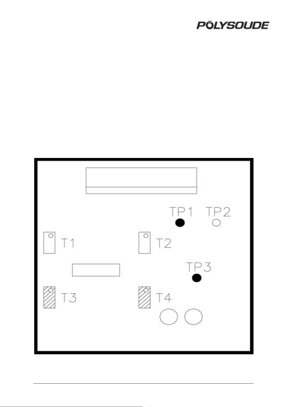
! Regulation of the measured current
voltage
The adjustment of the measured current
voltage is done on the card 217 00 636 after a
correct setup of the inverter unit. In order to
verify the supplied current, you can insert a
shunt between the power source and the torch.
A Connect a voltmeter between the test
points TP3 (0 V) and TP1.
B Connect a torch capable of supporting
200 A.
C Start a "with arc" cycle without
pulsation, with a current of 200 A. The
value read must be 4 V. If not, adjust it
with the potentiometer T3.
D Start another cycle with a current of 10
A. The value read must be 0.2 V. If
not, adjust it with the potentiometer T4.
E Repeat operations C and D until the
setup is correct.
Fig. 4.4: Potentiometer for adjusting the current voltage
measurement
MAN. PS 254 EN – Ind. 2 59
Page 61
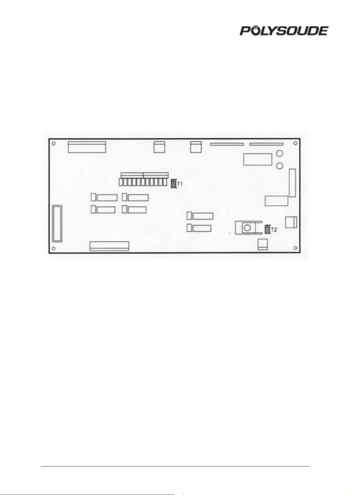
! Adjusting the contrast and brightness
of the display
These adjustments are made on the 21700634
synoptic card.
The contrast adjustment is made with
potentiometer T1, and the brightness
adjustment with potentiometer T2.
Fig. 4.5 : Adjusting the contrast and
brightness of the display (synoptic card
21700634)
60 MAN. PS 254 EN – Ind. 2
Page 62
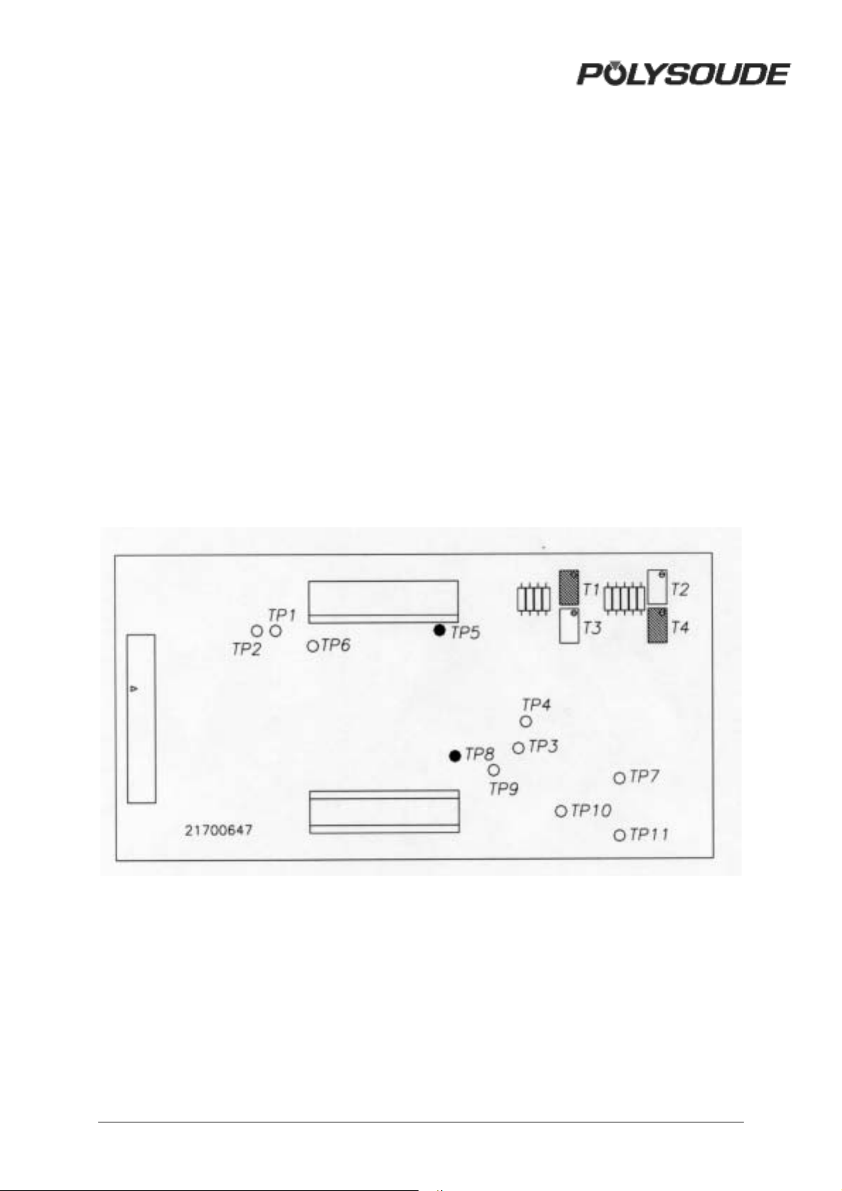
4.1.3. Adjusting the rotation speed of
welding heads with tachometry (optional)
! Regulation of tacho card 21700647
A Select the G009 factor of R30
parameter.
B Connect a power supply adjustable
from 0 V to 10 V between pins J (+ of
the power supply) and F (0 V of the
power supply) of rotation plug FA3.
C Connect a frequency measurer
between the test points TP5 and
TP8.
D With 10 V from power supply, adjust
potentiometer T4 to read a frequency
of 1100 Hz.
E With 1 V from power supply, adjust
potentiometer T1 to read a frequency
of 110 Hz.
F Repeat operations D and E until the
set-up is correct.
G Connect a power supply adjustable
from 0 V to 10 V between pins J (0 V
of the power supply) and F (+ of the
power supply) of rotation plug FA3.
H Connect a frequency measurer
between the test points TP5 and
TP8.
I With 10 V from power supply, adjust
potentiometer T2 to read a frequency
of 1100 Hz.
J With 1 V from power supply, adjust
potentiometer T3 to read a frequency
of 110 Hz.
K Repeat operations I and J until the
set-up is correct.
Fig. 4.6 : Potentiometers to adjust the speed of welding heads with tachometry
MAN. PS 254 EN – Ind. 2 61
Page 63
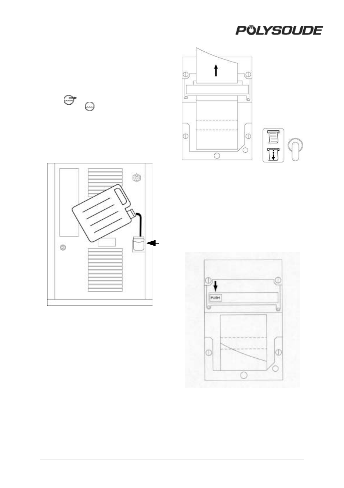
4.1.4. Coolant
Please make sure that the coolant level in the
reservoir of the power source is always
maintained. We advise you to change the
coolant once a year. Pump out the used liquid
by connecting a hose to the coolant outlet
(symbol ) and press the button
BT 15 (symbol )on the remote control
pendant. Pure, clean water should be used for
rinsing the cooling circuit. The refilling of the
coolant reservoir is made by the top of the
power source. NOTE : Only use coolant
recommended by Polysoude. The use of any
other coolant will void any warranty
commitment.
Fig. 4.8 : Change of paper roll
! Change of ribbon
To change the ribbon in the printer, you have
to open the cover (unscrew the 2 screws). The
ribbon is situated below the printer block.
Press on «PUSH» to take it out. To insert a
new ribbon, push it slightly to the top when
inserting it. Insert the paper into the slot of the
cover before closing it.
Fig. 4.7 : Coolant inlet
4.1.5. Printer
! Loading paper to the printer
The paper has to be loaded with the power
source turned on. To change the paper roll,
you have to open the cover (unscrew the 2
screws). Take out the empty roll and insert the
end of the new paper roll into the printer. The
paper advances by pushing the printer switch
Fig. 4.9 : Change of ribbon cartridge
SY 29 downwards. Insert the paper into the
slot of the cover before closing it.
62 MAN. PS 254 EN – Ind. 2
Page 64
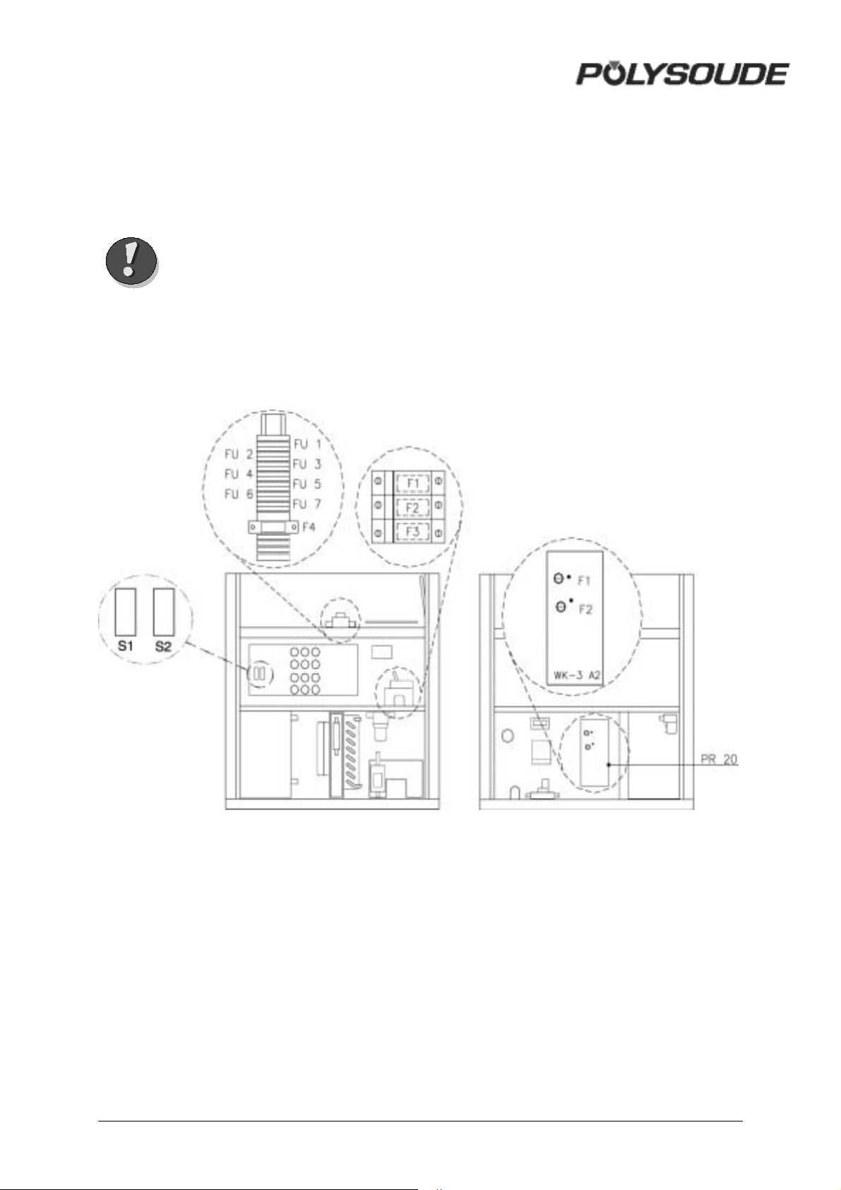
4.2. Maintenance and
troubleshooting
4.2.1. Replacing fuses
Warning A fuse blowing out indicates
in most cases a problem
somewhere in the electrical
installation. You must
resolve the problem before
replacing the fuse. Be careful
when switching on the
machine after you change a
fuse.
You will find the fuses in four areas:
• The sector fuses F1, F2, F3 are situated in
the main divider. To access this, you need
to remove the left side plate of the
generator, after having already removed
the roof.
• The fuses protecting the secondary
transformer (FU1 - FU7) can be found on
the top level and are accessible just by
removing the roof of the generator.
• Two fuses RF1 and RF2 are situated on
the relay card WK-3 A2 and another one is
located on the +12V/ +5V power supply
card.
Fig. 4.14: Location of the fuses
MAN. PS 254 EN – Ind. 2 63
Page 65

4.2.2. Trouble shooting
! Noted defect when operating
defect cause What to do
Impossible to switch the
power source on
The power source is
working while the main
switch is in the Off-position
The power source is
switche off when the weld
starts
The weld cycle or an axis
(rotation, wire, gas, cooling
circuit) start by themselves
Some of the buttons on the
remote control pendant
don't work
The program number on the
display does not
correspond with the
number chosen on the
remote control pendant
Some programs are deleted
from the memory of the
power source
- Fuses F1, F2, F3, F4 or FU 3 defect
- Mains supply interrupted
- Plug, cables or connections defect
- Remote control pendant BP 1436 defect
(emergency stop button pushed) or not connected
- Relay K1 defect or not connected
- Main switch defect
- Wrong choice of input voltage
- +12 V modul defect
- Card 217 00 634 defect
- The mains supply cable is connected to the wrong
contact
One phase of the mains supply is interrupted - Check and correct
- The power source is not connected to the ground
- Remote control pendant BP 1436 defect
- Shielding of the remote control pendant cable is
damaged
- Card 217 00 634 defect
- Remote control pendant defect
- Synoptic card 21700634 defect
- - Remote control pendant BP 1436 defect
- Card 217 00 634 defect
- Wrong action (programs deleted with the button SY
23)
- Card 217 00 633 has been replaced
- RAM memory on card 217 00 633 defect
- Change (§. 4.2.1)
- Check
- Check and repair
- Check and change or repair
- Check and change or repair
- Check and change
- Check and correct (§ 2.2.3).
- Replace
- Replace
- Check and correct
- Make a connection
- Check and change or repair
- Replace cable
- Replace
- Check and repair or change
- Replace
- Check and change or repair
- Replace
- Reload the programs
- Reload the programs
- Replace RAM memory
64 MAN. PS 254 EN – Ind. 2
Page 66
defect cause What to do
Some parameters stored on
the memocard have been
altered
Impossible to modify values
of weld parameters (buttons
""+"" and ""-"" are not
working)
Some buttons of the
programming keyboard
don't answer
Display dark - electric supply card + 5 V defect
Impossible to start a weld
cycle (the indicator LED on
the remote control pendant
is flashing)
Impossible to start a weld
cycle with a manual torch
Distortion of the display
during ignition of the arc
Poor gas flow - gas conduit inside the welding head clogged
Any rotation movement
(welding head) or wire
feeding, any error message
appears
- Memocard defect - Use new memocard to store
- - Key-operated switch SY 25 in position
""modification not allowed""
- keyboard defect
- card 217 00 634 defect
- RAM memory on the card 217 00 633 defect
- Fuse FU 1 or FU 2 defect
- wrong wiring of the cable connection of the manual
toch
- card 217 00 633 defect
- wrong wiring of the cable connection of the manual
toch
- card 217 00 633 defect
- electric supply card + 5 V defect - check fuse and change
- gas flowmeter defect
- solenoid gas valve defect
- shear pin broken - replace shear pin (see operation
programs
- Put the switch in the
""modifications allowed""
position
- can only be checked by a
qualified electrician
- change card
- check fuse and change
- change card or RAM memory
- Check and change
- check program number (§ 3.3.1)
- check and change
- change card
- check and clean
- can be checked only by a
qualified specialist
- can be checked only by a
qualified specialist
manual of the welding head or
wire feeder for details)
MAN. PS 254 EN – Ind. 2 65
Page 67

! Display of an error code
Error
code
10
11 or 12
22
23
24
Possible causes What to do
- Shielding gas cylinder empty or valve closed.
- Poor connection of the shielding gas coupling.
- Fuse F 1 on card WK-3 defect.
- Solenoid valve defect.
- Level of cooling liquid low.
- Hoses of the cooling circuit buckled or knotted, filter clogge.
- Fuse F 2 on card WK-3 defect.
- Shunt for cooling circuit security not mounted (use of air cooled
welding heads only).
- Quick gas coupling of the welding head not fastened.
- Pump defect.
- Hose bundle defect (welding heads MU).
- Weld current cable poorly connected or interrupted.
- Bad position of the ground cable.
- Wrong gas flow adjustm ent.
- Electrode polluted or distance workpiece / electrode too high.
- Hose bundle defect (welding head MU).
- Ignition aid defect or in wrong position (welding heads MU, TP, TS...).
- Wrong shielding gas (He).
- Power source poorly adjusted.
- Electrode tip poorly ground or worn out.
- Distance workpiece / elektrode wrong.
- Poor shielding gas protection.
- Programmed weld current too low, when the arc starts.
- Ignition aid defect or in wrong position (welding MU, TP, TS...).
- Electrode has touched the workpiece.
- Electrode has touched the filler wire.
- Ignition aid defect or in wrong position (welding MU, TP, TS...).
- Lack of insulation between welding head and wire guide support.
- Card 217 00 633 defect.
- Inverter unit defect (card TRDC2).
- Check and change or open.
- Check and connect properly.
- Check and change (§ 4.2.1).
- Can be checked only by a
qualified specialist.
- Check and correct.
- Keep in proper conditions.
- Check and change (§ 4.2.1).
- Refer to §2.3.3 to make
connections properly.
- Check and connect properly.
- Can be checked only by a
qualified specialist.
- Change.
- Check and change.
- Deplace ground cable (refer to§
3.2.3 or 2.3.7).
- Check.
- For correct electrode settings,
refer to operating manual of the
welding head.
- Change.
- Position ignition aid correctly.
- Try argon.
- Can be checked only by a
qualified specialist.
- Refer to operating manual of
the weld head for correct set up
and change of the electrode.
- Correct.
- Check gas flow, clean or
change gas lens.
- Correct.
- Change or correct position.
- Correct
- Change the position of the wire
inlet move
- Move
- Check and correct
- Replace
- Call After Sales Service
66 MAN. PS 254 EN – Ind. 2
Page 68

Error
Possible causes What to do
code
25 - Mains input voltage too high.
- Phase failure of the mains input.
- Settings of input power jumpers wrong.
- Fuse S1 or S2 of the inverter unit defect.
- Inverter unit defect (Karte TRDC2).
- Card 217 00 633 or card 217 00 636 defect.
26 - Mains voltage too low
- Phase failure of the mains input.
- Settings of input power jumpers wrong.
- Fuse S1 or S2 of the inverter unit defect.
- Inverter unit defect (Karte TRDC2).
- Card 217 00 633 or card 217 00 636 defect.
27 - Too much power required from the power source.
- Constricted air circulation.
- Settings of input power jumpers wrong.
- Phase failure of the mains input.
- Fuse S1 or S2 of the inverter unit defect.
- Inverter unit defect (Karte TRDC2).
- Card 217 00 633 or card 217 00 636 defect.
- Fan defect.
28 - Phase failure of the mains input.
- Settings of input power jumpers wrong.
- Fuse S1 or S2 of the inverter unit defect.
- Inverter unit defect (Karte TRDC2).
- Card 217 00 633 or card 217 00 636 defect.
29 - Phase failure of the mains input.
- Settings of input power jumpers wrong.
- Fuse S1 or S2 of the inverter unit defect.
- Polygaine hose bundle defect (welding heads MU).
- Wrong position of switch S3/1 on the card 217 00 633.
- Poor adjustment of the power source.
30 Wrong reference number R30 for the identification of the welding head
programmed.
- Problems caused by friction or jamming of the weldinghead or wire
30 or 40
31 or 41 - Problems caused by friction or jamming of the weldinghead or wire
32 or 42 - Fuse FU 7 defect
feeder.
feeder.
- Fuse FU 4 defect.
- Card 217 00 633 defect.
- Impulse generator of the welding head or wire feeder defect.
- Bad cable connection between the power source and the motor.
- Card 217 00 633 defect.
- Transformer T1 defect.
- Check and modify the
connection cable position of the
transformer inside the power
source.
- Check and correct.
- Correct.
- Check and correct.
- Can be checked only by a
qualified specialist.
- Change.
- Check and modify the
connection cable position of the
transformer inside the power
source.
- Check and correct.
- Correct.
- Check and correct.
- Can be checked only by a
qualified specialist.
- Change.
- Respect duty cycle of the power
source (§ 1.3.2).
- Watch for minimal distance
between the power source and
surrounds (§ 2.2.2).
- Correct.
- Check and correct.
- Check and correct.
- Can be checked only by a
qualified specialist.
- Change.
- Check. The fan can be changed
only by a qualified specialist.
- Check and correct.
- Correct.
- Check and correct.
- Can be checked only by a
qualified specialist.
- Change.
- Check and correct.
- Correct.
- Check and correct.
- Change.
- Check and correct.
- Adjustments can be carried out
only by a qualified specialist.
- Correct.
- Check and remove dirt and
foreign parts.
- Check and remove dirt and
foreign parts.
- Change.
- Change.
- Change.
- Check and change.
- Can be checked only by a
qualified specialist.
- Change.
- Can be checked only by a
qualified specialist.
MAN. PS 254 EN – Ind. 2 67
Page 69
Error
Possible causes What to do
code
51 - No ground connection of the power source.
- Remote control pendant BP 1436 defect.
- Shielding of the cable of the remote control pendant BP 1436 defect.
- Card 217 00 634 defect.
52 - Phase failure of the mains input.
- Fuse S1 or S2 of the inverter unit defect.
- Remote control pendant BP 1436 defect.
- Card 217 00 633 or card 217 00 634 defect.
53 - Kurzzeitiger Netzspannungseinbruch.
- Karte 217 00 633 defect.
a) Closed welding heads of the MW, H or UHP type:
- Welding head is not in the home-position.
54
56 - Memo card upside down in the card reader.
60 - Printer defect
62 - After the end of the last weld cycle, the power source has been
70 - Memo card is not introduced into the card reader SY 26.
71 Memo card has been removed from the card reader before the end of
72 - The card 217 00 633 has been changed. - Choose with the switch BT 4 for
73 - Any program stored on the memo card.
74 - Load from a memo card that has been removed from the card reader
75
- Limit switch of the welding head defect or badly adjusted.
b) Welding heads of other types (without tacho):
- The pins D and E of the rotation motor cable are not short-circuited in
the plug connector.
c) All types of welding heads:
- Card 217 00 633 defect.
- Wrong reference number R30 for the identification of the welding
head programmed.
- Flat cable for the connection between card 217 00 633 and card 217
00 634 defect or loose.
- Switch S1/1 on the card 217 00 634 in the wrong position.
- 21700634 card defect
turned off and on again.
- The program number (YY) used for the weld cycle is different from
the program number (XX), which is actually chosen.
- Memo card is not introduced correctly into the card reader SY 26.
the storage.
- Memo card introduced in the wrong way into the card reader SY 26.
before the end of the storage.
- The program stored on the memo card comes from a different tye of
power source.
- Correct.
- Check.
- Replace cable.
- Change.
- Check and correct.
- Check and correct.
- Check.
- Change.
- Prüfen und Schweißstromquelle
erneut einschalten.
- Austauschen.
- Turn welding head in the homeposition.
- Check and change or correct.
- Correct.
- Change.
- Correct.
- Watch for right position if you
introduce a memo card.
- Change or correct.
- Check and call for
maintenance.
- Replace
- Change
- Operate a new weld cycle.
- Choose program number YY
and restart printing of the weld
cycle report with the switch SY
28.
- Introduce memo card.
- Remove the memo card and
introduce it correctly.
Repeat storage (before removing
the memocard, wait until indicator
SY 13 becomes dark).
selecting the program number all
numbers from 0 to 15 one after
another.
- Use memo card with a program
stored on it.
- Remove card and introduce it
correctly into the card reader SY
26.
- Use a new memocard.
- - Use only programs made for a
power source PS 254.
- The position of the switch S3/1 or S3/4 on the card 217 00 633 is
wrong.
- Set switches to the ""OPEN""
position.
68 MAN. PS 254 EN – Ind. 2
Page 70
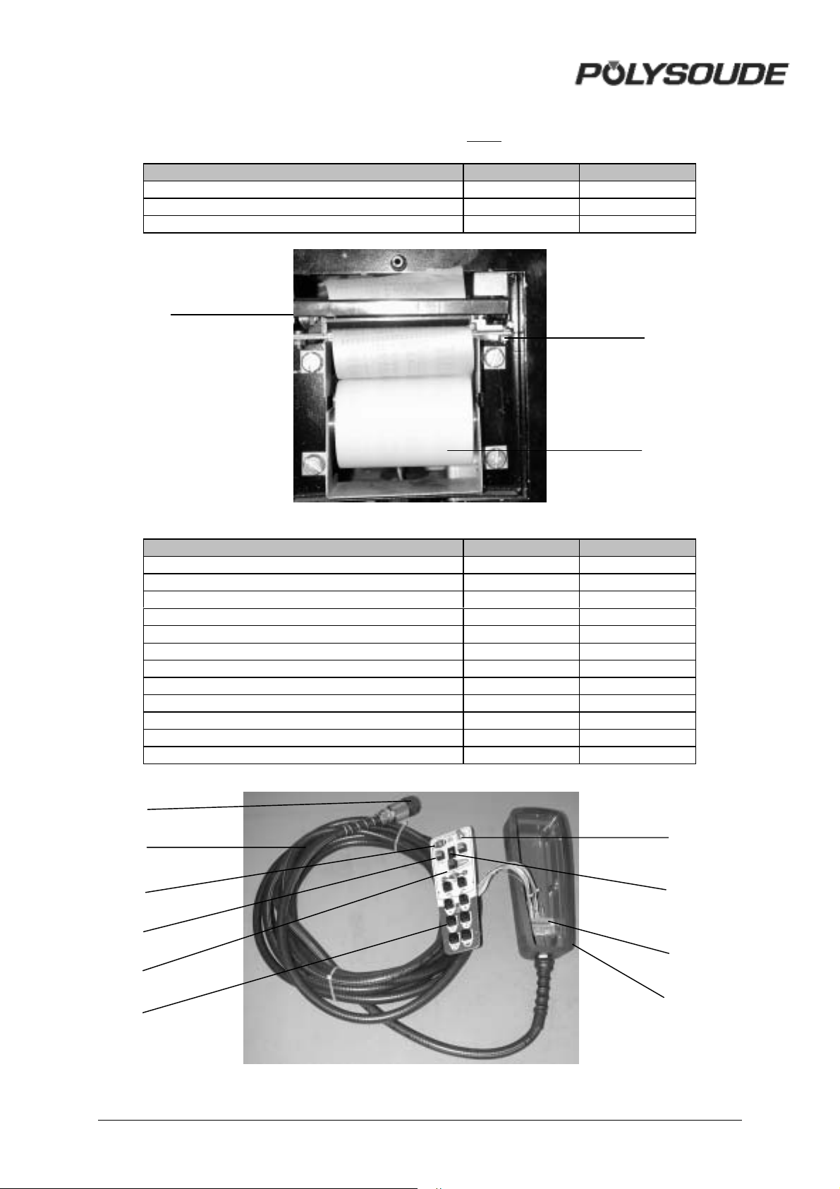
4.2.3. Spare parts ( See “summary spare parts” pages 84/85)
Désignation Repère Référence
Ribbon for printer 25 00590064
Printer 26 00629078
Paper for printer 27 00590066
25
Fig. 4.16 : Front view
26
27
Désignation Repère Référence
Remote control pendant 14360000
Remote control pendant plug 28 00563085
Câble télécommande complet 29 14369999
Toggle switch for pendant 30 00542006
Grey remote control pendant button 31 00549067
Red remote control pendant button 32 00549065
Black remote control pendant button 33 00549066
Emergency stop button 34 00542070
Red cover for emergency stop button 35 00542071
Coding wheel 36 00543016
Interconnection card 37 21700627
Coque caoutchouc pour télécommande 38 17375299
28
29
30
31
32
34,35
36
37
33
38
MAN. PS 254 EN – Ind. 2 69
Page 71

Fig. 4.17 : Remote control
Désignation Référence
Ground cable 64599801
Flowmeter Argon 75501002
Flowmeter Argon/Hydrogen 71701421
Cooling liquid 75110071
Fuses 75501207
4.2.4. Circuit description
! Remark
The following information refers to the wiring
scheme of the PS 254 (Ref. 1700 xx xx) and
the remote control pendant (Ref. 1436 xx xx or
1737 xx xx) as well as to the sequencer card
(Ref. 217 00 633), the synoptic card (Ref. 217
00 634), the source interface card 217 00 690,
the memory circuit interface card (Ref. 217 00
680), and the interface tacho-impulses (Ref.
217 00 647).
The signals are described by an abbreviated
name corresponding to their function. It is
useful to recognise that a signal preceded by a
bar " / "signifies that it is active at the low level
(0 V).
The numbers inscribed at the bottom right of
the synoptic blocks relate to the folio numbers
of the corresponding dossiers. For example,
the number 08 in the block "Gas control" of the
sequencer card corresponds to folio 08 of
dossier number 21700633.
! The power switch
The power switch consists of a self holding
switch K2. When the power is turned on, the
K2 switch is activated. It then remains in this
state until the power is turned off (K1 is
activated). K1 is directly linked to the
emergency stop button via the synoptic card
(folio 21700634). The loss of voltage or the
pressing of the emergency stop button
activates K1, which immediately cuts off the
power supply. To restart the weld cycle you
must turn on the machine again with the power
switch. This system has been designed for
safety reasons.
! General presentation and wiring
scheme
The functioning of the PS 254 is principally
controlled by 2 cards: the 21700633 sequencer
card and the 21700634 synoptic card. These
two cards are linked together by a data bus
I²C. This connection is built up via the memory
circuit interface card 217 00 680.
The sequencer card ensures the correct follow
up of weld cycles by the power source. It is
linked to the power supply, the rotation motor,
the wire feed motor, and watches for the
correct functioning of the gas valves and the
cooling circuit. The microchip is also found on
this card.
The synoptic card, controlled by the sequencer
card, controls the peripheral units (keyboard,
indicators and display screen), the memo card,
the remote control pendant and the printer.
70 MAN. PS 254 EN – Ind. 2
Page 72
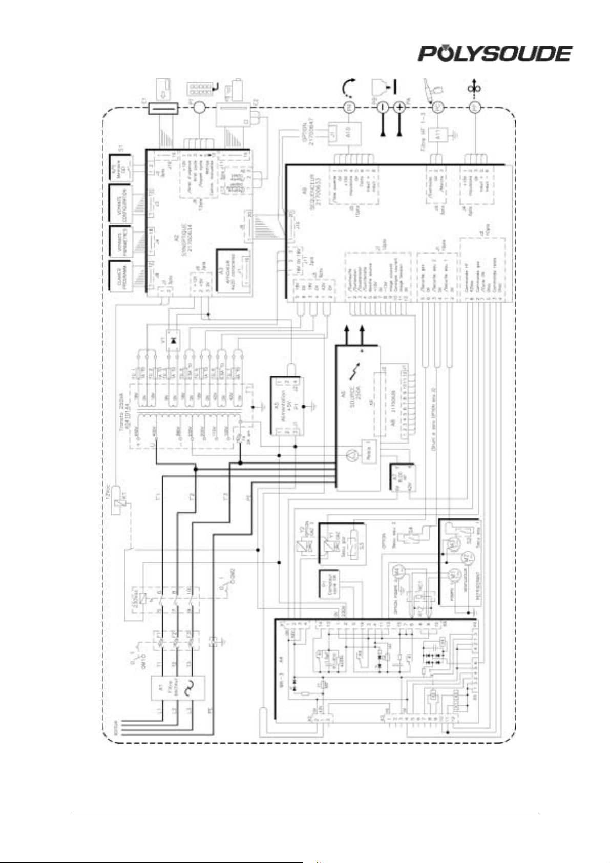
Fig. 4.18 : Wiring scheme of PS 254
MAN. PS 254 EN – Ind. 2 71
Page 73
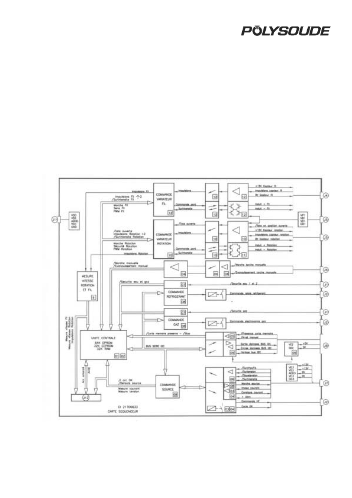
! The sequencer card (21700633)
The sequencer card includes several block
functions:
• Central program unit (CPU) composed
principally of the microchip and the
memory.
• Power control.
• Rotation motor control, based on the
principle of PWM (Pulse Width
Modulation).
• Wire motor control, identical to the control
of the rotation motor.
• Shielding gas control.
• Coolant control.
• Interface with the manual torch
• Interface with the I²C bus for the external
links and especially with the synoptic card.
• Power supplies.
Fig. 4.19 : Sequencer card
72 MAN. PS 254 EN – Ind. 2
Page 74

! The synoptic card (21700634)
The synoptic card interfaces with the following
peripheral units:
• Remote control pendant.
• Programming keyboard.
• Synoptic on the front panel.
• Display on the front panel.
• Printer.
• Memo card.
It is controlled by the sequencer card via an I²C
link.
The interface with the remote control pendant
is made by constantly checking the state of the
buttons with a line and column system. By
successively activating the different lines and
testing the columns it is determined which
buttons or switches have been activated.
The stop command BT 7 is linked directly to
the sequencer card, without passing via the I²C
bus. The emergency stop button BT 2 on the
remote control pendant is linked also to the
power on/off switch. This ensures the safety of
the users in the case of a cycle stop or an
emergency stop.
The programming keyboard is based on the
same principle. Only the key switch
"Modification authorised or not" has a direct
link.
The interface with the synoptic indicators is
made by multiplexing. The indicators are not
permanently supplied with power, but instead
by a signal (multiplexing supply) which has a
frequency of several hundred Hertz.
The contrast and brightness of the screen is
controlled by the synoptic card. The procedure
for their adjustment is given in paragraph
9.2.6.
The memo cards used with the PS 254 are
compatible with the databus I²C. The presence
of a signal "Memo card engaged", resulting
from a contact in the connector, authorises all
other connections, including the 5 V power
supply. The card is thus protected from
overloads during its insertion and its removal.
MAN. PS 254 EN – Ind. 2 73
Page 75
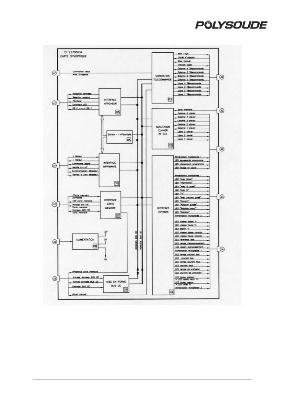
Fig. 4.20 : Synoptic card
74 MAN. PS 254 EN – Ind. 2
Page 76
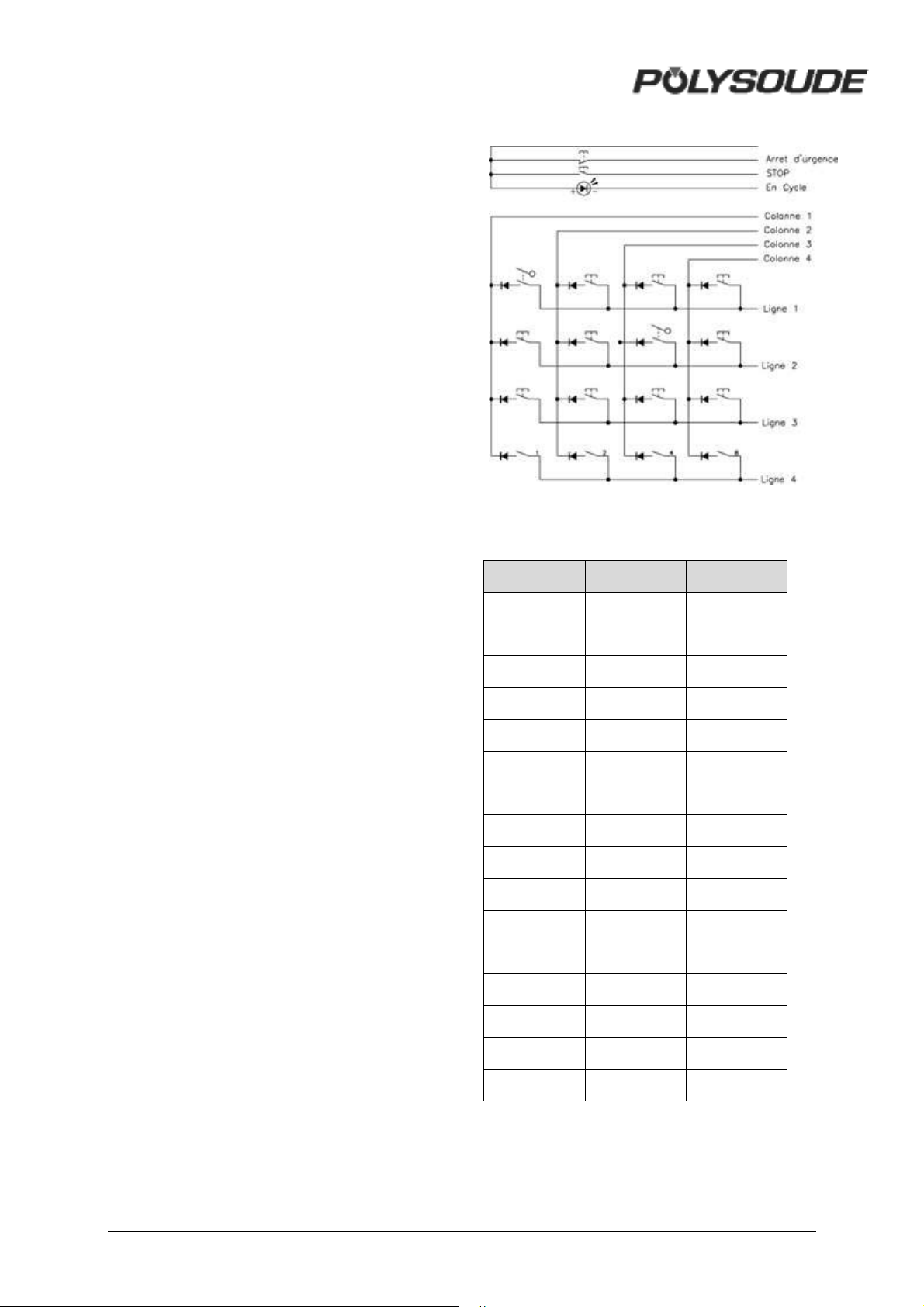
! The source
The power command, generated by the
sequencer card, is an analogical signal 0 to 10
V. At 10 V, it corresponds to 160 A, and at 0 V
it corresponds to the minimum current of the
source, 4 A, for the 160A range; at 10 V it
corresponds 50 A, and at 0 V it corresponds 4
A, for the 50 A range.
A logic order active at high level (15 V) controls
the running of the source.
The source sends a signal indicating that it is
overheated. The signal is released by the
sequencer card to stop the weld cycle and
display the code of the detected fault (27).
The high frequency generator is controlled by
a signal emitted from the sequencer card. A
relay contact ensures that this action occurs.
The other pole of contact is linked to an
alternative voltage of 42 V.
! The remote control pendant
The buttons on the control pendant are
controlled by the synoptic card (21700634).
Most of the buttons are tested by the line and
column method: A high level signal is placed
on a line and the columns are tested. If a
column is at a high level, this shows that the
button associated with this line and column
has been pressed. The next line is tested
afterwards, and so on. Only the two safety
buttons are directly linked.
The «In cycle» indicator is a light emitting
diode LED.
Fig. 4.21 : Remote control pendant logic
LINE COLUMN BUTTON
11BT 1
12BT 16
13BT 11
14BT 14
21BT 5
22BT 15
23BT 12
24BT 9
31BT 6
32BT 10
33BT 13
34BT 8
41BT 4 (1)
42BT 4 (2)
43BT 4 (4)
44BT 4 (8)
MAN. PS 254 EN – Ind. 2 75
Page 77
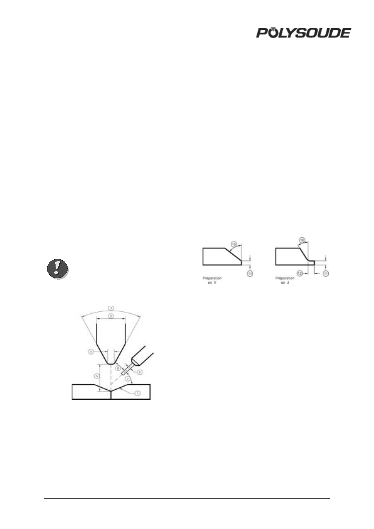
5. APPENDIX
5.1. Built-in programs
The Polysoude weld lab developed these
programs for mild steel and stainless steel
tubes. Starting from frequent applications they
represent the base to work out rapidly your
own weld programs. Please look for a program
close to your application in order to modify it.
Before you can use such a built-in program
you have to copy it in one of the 16 user
program places in the memory of the power
source (for detailed information, see
Programming Manual). Afterwards you can
modify the program to fit your special
application.
For all applications, Argon is used as shielding
gas. The programs are listed in function of the
welding head (closed chamber, MU III, or
TS/TP), the material (mild steel or stainless
steel), the diameter and the wall thickness of
the tubes to be welded. In case of tube to tubeplate welds, a difference is made between
"flush" and "protruding" tubes.
If filler wire is used, its diameter is always 0.8
mm.
The set-up of a weld may influence
considerably its result. The set-up is explained
below and, whenever necessary, added to the
programs.
1: Tube end preparation.
2: Electrode diameter.
3: Tip angle.
4: Flat.
5: Distance electrode-workpiece.
6: Diam eter of filler wire.
7: Angle between wire and workpiece.
8: Start position of the weld.
9: Start position of the weld.
10: Weld preparation angle.
11: Thickness of land.
12: Length of the land (for J
preparation).
Warning If multipass welding is
necessary, the parameter
values for the passes are
given in the tables without
repeating diameter and
thickness of the tubes.
Fig. 5.1 : Weld set-up
Fig. 5.2 : Weld preparation
76 MAN. PS 254 EN – Ind. 2
Page 78
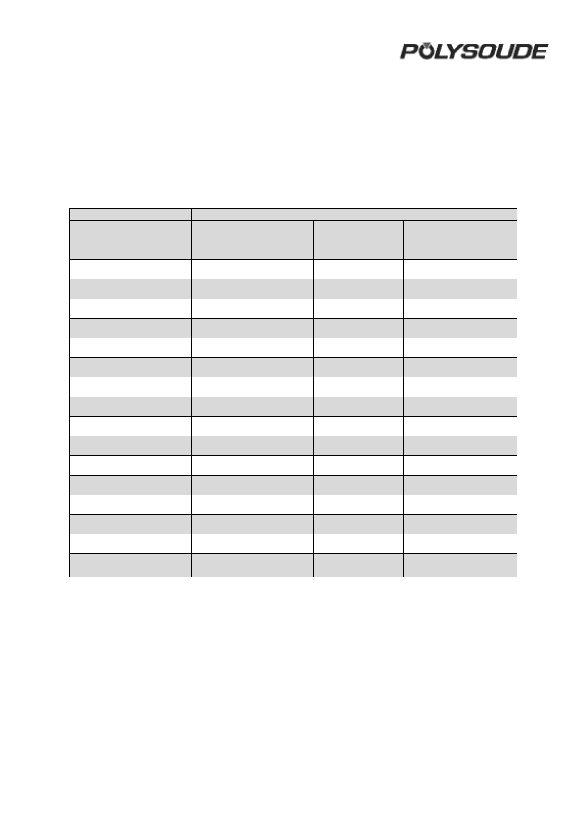
5.1.1. Closed chamber welding heads or
MU heads without filler wire
To use these programs for enclosed welding
heads, a square-butt preparation is necessary.
The programs which are valid for MU III
welding heads are indicated by a star in the
appropriate column.
Tubes to be welded Set-up before welding Range
Material Ø OD
mm mm mm degree mm mm
Stainless
5 1 1.6200.2 0.8 1 X
Wall
thicknessØelectrode
Tip angle Nose
Distance
electrode/w
orkpiece
Number
of built-in
program
Also valid
for MU III
welding
heads
PS 254
Stainless
Stainless
Stainless
Stainless
Stainless
Stainless
Stainless
Stainless
Stainless
Stainless
Stainless
Stainless
Stainless
Stainless
Stainless
6 0.6 1.6 20 0.1 0.8 2 X
6.35 0.9 1.6 20 0.2 0.8 3 * X
8 1 1 20 01 0.8 4 * X
9.52 1.65 1.6 15 0.1 0.8 5 X
10 1.55 1.6 20 0.1 1 6 * X
10.5 0.4 1.6 20 0.1 0.8 7 * X
11 0.2 1.6 15 / 0.35 8
12 1 1.6 20 0.1 0.8 9 * X
12.7 0.8 1.6 20 0.1 0.8 10 * X
15.8 0.2 1.6 15 / 0.4 11
16 0.8 1.6 20 0.1 0.8 12 X
16 2.25 2.4 20 0.2 0.8 13 * X
17.2 2.3 2.4 30 0.2 0.8 14 * X
22 1.25 2.4 30 0.2 1 15 * X
25 1 2.4 30 0.2 1 16 * X
MAN. PS 254 EN – Ind. 2 77
Page 79
Tubes to be welded Set-up before welding Range
Material Ø OD
mm mm mm degrés mm mm
Stainless
25 1.2 2.4 30 0.2 1 17 * X
Wall
thicknessØelectrode
Tip angle Nose
Distance
electrode
workpiece
Number
of built- in
program
Also valid
for MU III
welding
heads
PS 254
Stainless
Stainless
Stainless
Stainless
Stainless
Stainless
Stainless
Stainless
Stainless
Stainless
Stainless
Stainless
Stainless
25 2.5 2.4 30 0.2 1.2 18 * X
26.9 3.6 2.4 30 0.2 1.2 19 * X
38 1.2 2.4 30 0.2 1 20 * X
40.5 0.4 2.4 20 0.1 0.6 21 * X
48.7 2 2.4 30 0.2 1.2 22 * X
51 1.2 2.4 30 0.2 1 23 * X
51 1.8 2.4 30 0.2 1.2 24 * X
63.5 0.7 2.4 20 0.2 0.9 25 * X
63.5 1.5 2.4 30 0.2 1.2 26 * X
88.9 1.6 2.4 30 0.2 1.2 27 * X
88.9 2 2.4 30 0.2 1.4 28 * X
88.9 3 2.4 30 0.2 1.6 29 * X
114.3 3 2.4 30 0.2 1.6 30 * X
78 MAN. PS 254 EN – Ind. 2
Page 80
5.1.2. MU open welding heads with filler
wire
Warning For some welds the distance
electrode-workpiece has to
be modified at the end of the
cycle when the beginning of
the seam is overwelded.
These programs are marked
with a star in the last column
of the set-up before welding.
Tubes to be welded
Ø OD
Material
mm
Stainless
Stainless
Stainless
Stainless
Stainless
Stainless
Stainless
Stainless
Mild steel
Mild steel
Mild steel
Mild steel
Mild steel
Mild steel
Mild steel
33.7 3.2
51 1.8
51 3
60.3 2.5
60.3 4
114.3 2.5
114.3 3
168 4
25 3.2
38 3
51 3
51 4
60.3 3
88.9 4
114.3 3.9
Wall thickness
mm
V 37.5° 0.4
Square-butt
V 37.5° 0.2
Square-butt
Square-butt
Square-butt
V 37.5° 0.2
V 37.5° 0.2
V 37.5° 0.2
1.5mm land
V 37.5° 0.2
1 mm nose
V 37.5° 0.2
Preparation
mm nose
mm nose
J 30°
0.9 mm
nose 1.5
mm land
mm nose
mm nose
mm nose
J 30° 1.4
mm nose
mm nose
J 30°
1.5 mm
land
mm nose
Set-up before welding Range
Nose
Tip angle
Ø Electrode
mm
2.4 40 0.3 2.5 25 3 12 H 41 *
2.4 40 0.3 2.5 20 3 12 H 43
2.4 40 0.3 2.5 25 3 10H30 44 *
2.4 40 0.3 2 20 2.5 10H30 46 *
2.4 40 0.3 2 25 3 10H30 47 *
2.4 40 0.3 3 20 3.5 12 H 2 48
2.4 40 0.3 2.5 20 3 12 H 51 *
2.4 30 0.3 2 25 2.5 10H30 52 *
2.4 40 0.2 2 25 2 10H30 56 *
2.4 40 0.2 2 20 2.5 10H30 1 57 *
2.4 40 0.2 2.5 20 3 12 H 2 58
2.4 40 0.2 2 15 2.5 10H30 59 *
2.4 40 0.2 2 30 2 10H30 1 61 *
2.4 40 0.2 2.5 20 3 12 H 2 62
2.4 40 0.2 1.5 25 2.5 10H30 1 63 *
2.4 40 0.2 2.5 20 3 12 H 2 64
2.4 40 0.4 2 35 1.5 10H30 1 65
2.4 40 0.2 2 10 2.5 12H 2 66
2.4 40 0.2 1.5 25 2 10H30 1 67 *
2.4 40 0.2 3 10 3.5 12 H 2 68
mm
degrees
piece
Distance
electrode/work
Distance
Wire angle
électrode/wire
Layer
Start position
mm
mm
degrees
1 53
2 54
Built-in program number
PS 254
Adjust at the end of cycle
X
X
X
X
X
X
X
X
X
X
X
X
X
X
X
X
X
X
X
X
X
X
MAN. PS 254 EN – Ind. 2 79
Page 81
5.1.3. TS/TP welding heads for welding
of tubes to tubesheet
Tube to tubesheet welds may have two
geometrical shapes : flushing or protruding
tubes. For welds of flushing tubes, one pass is
required. For welds of protruding tubes, make
two passes (one with wire and one without
wire). In this case a welding bevel is needed
on the workpiece (angle = 45°,
height: 1.5 mm). For leak resistant welds of
protruding tubes, make one pass (without a
bevel) and then a second pass corresponding
to the tube to be welded.
Tubes to be welded
Material
Stainless
Stainless
Stainless
Stainless
Mild
steel
Ø OD
mm
25 2
25 2
26.7 1.5
26.7 1.5
25 2.5
Wall thickness
mm
Tube
Flushing
Prot ruding
Flushing
Prot ruding
Flushing
Set-up before welding Range
Distance
Angle of torch
protruding/flushing
électrode/plaque
mm
piece
Distance
electrode/work
mm
Distance
electrode/wire
mm
Ø Electrode
mm
Nose
mm
Ø wire
N° of layer
Tip angle
degrees
number
Built-in program
0° 2.5 1 2 2.4 30° 0.2 0.8 1/1 81 X
15° 0.5 1.2 2.4 30° 0.2 1/2 83 X
15° 2 2 1.2 2.4 30° 0.2 0.8 2/2 84 X
0° 3 1 2.2 2.4 30° 0.2 0.8 1/1 85 X
15° 0.5 1.2 2.4 30° 0.2 1/2 87 X
15° 2 2 1.2 2.4 30° 0.2 0.8 2/2 88 X
30° 2 2 1.2 2.4 30° 0.2 0.8 1/1 90 X
PS 254
Mild
steel
Mild
steel
Mild
steel
25 2.5
25 3
25 3
Prot ruding
Flushing
Prot ruding
30° 0.5 1.2 0.5 2.4 30° 0.2 1/2 91 X
30° 2 2.2 1.2 2.4 30° 0.2 0.8 2/2 92 X
0° 2 1 1.2 2.4 30° 0.2 0.8 1/1 93 X
15° 0.5 1.2 2.4 30° 0.2 0.8 1/2 95 X
15° 2 2 1.2 2.4 30° 0.2 0.8 2/2 96 X
80 MAN. PS 254 EN – Ind. 2
Page 82
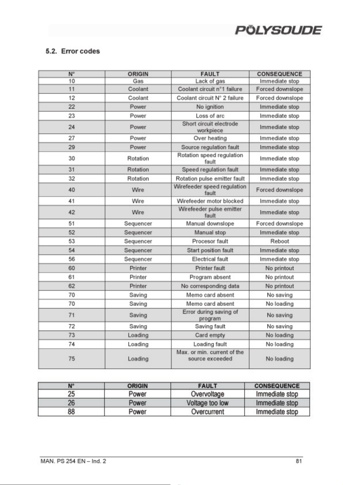
Page 83
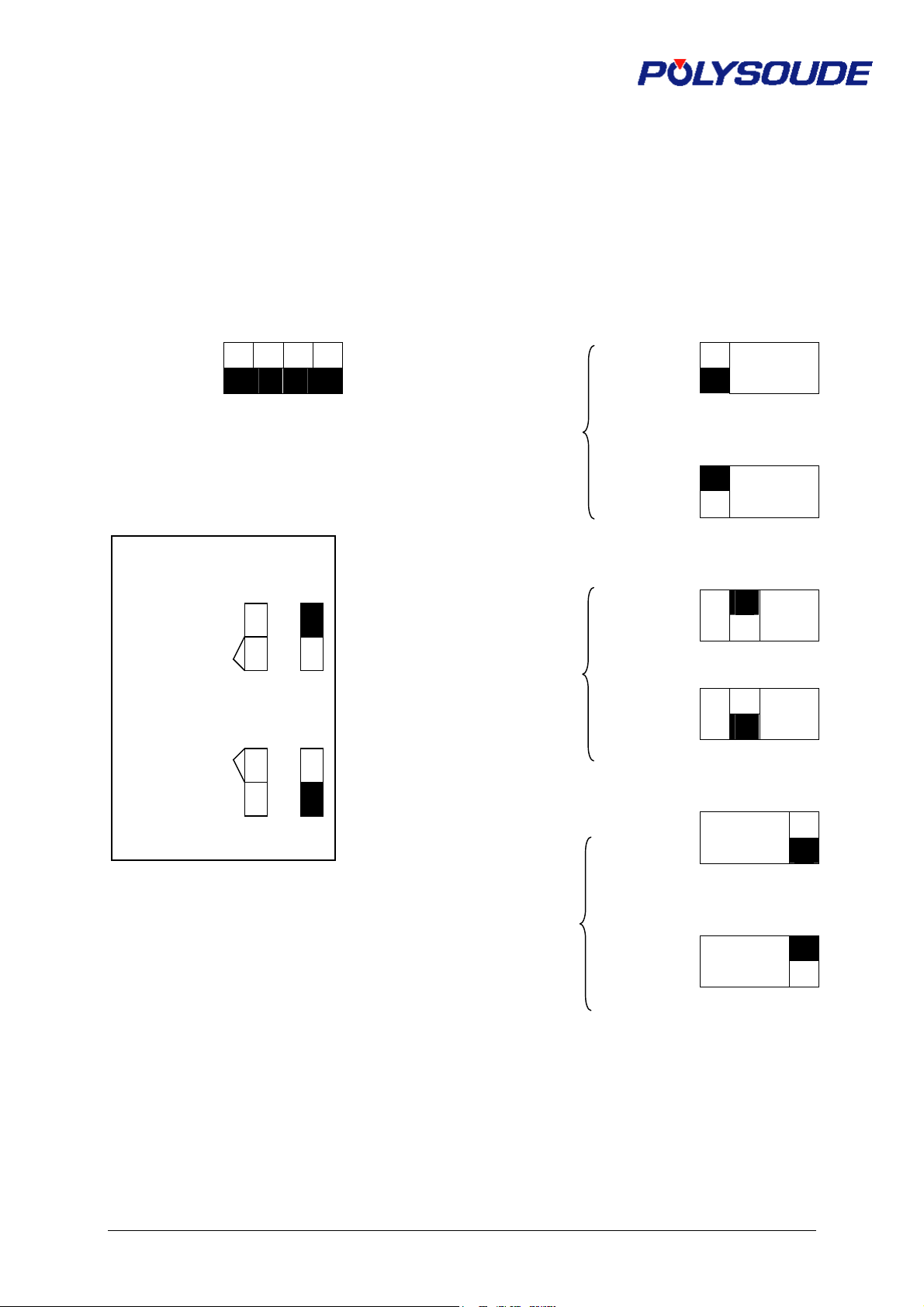
CONFIGURATION OF DIPS FOR PS 254
Card 21700633 21700634
S3 Function S1
Tachy
Extension
cable
current
display
Without
With
Without
With
Analog
Digital
1 2 3 4
1 2 3 4
1 2 3 4
1 2 3 4
1 2 3 4
1 2 3 4
Convention
Closed
Open
1 2 3 4
PS 254
Voltage and
84 MAN. PS 254 FR – Ind. 3
Page 84
RETURN OF MATERIAL
Please fill out and join this sheet when returning materiel to
POLYSOUDE
Z.I du Bois Briand
2 rue Paul Beaupère
BP 41606
44606 Nantes Cedex 3
Reseller / Person in charge :
Customer / Person in charge / Tel. :
EQUIPMENT RETURNED :
! Power source Type : Serial number :
! Welding head Type : Serial number :
! Coolant Type : Serial number :
! Other (specify designation) :
taken from :
! Power source Type : Serial number :
! Welding head Type : Serial number :
! Coolant Type : Serial number :
! Other(to be specified) : Serial number :
REASON FOR RETURN :
! Return after loan / of demonstration material
! Return of hired equipment
! Deficient delivery / incorrect order
! Return for modification (to be specified) :
! Return for revision
! Return for calibration
! Return for repair
please specify the type of the error : ! systematically
! occasionally
Description of breakdown :
! Other (please specify) :
MAN. PS 254 EN – Ind. 2 83
Page 85

Date : Signature:
84 MAN. PS 254 EN – Ind. 2
Page 86

SUMMARY SPARE PARTS
PARTN° DESIGNATION QTY
00503026 Display remote control pendant 1
00629079 Memory card (1 programme) 10
00629087 Relay-PC board 1
14360000 Remote control pendant 1
21700633 Sequencer PC board 1
21700634 Synoptic PC board 1
21700627 PC board interface for remote control pendant 1
00629086 H.F. striking unit 1
00545111 Main switch 1
00545112 Key locking switch 1
00629076 Current supply (+5 V) 1
14909804 Programming keyboard 1
17375299 Protection box for remote control pendant 1
71701418 Flowmeter Argon (Export) 1
00629078 Printer 1
75501002 Flowmeter Argon (France) 1
71701421 Flowmeter Argon/Hydrogen 1
14369999 Cable complet for remote control pendant 1
21700636 Current/voltage interface 1
21700647 Interface tacho impulse 1
00629080 Power unit 250 A 1
75501207 Set of fuses 1
64599801 Return cable 9 m 1
75301335 Electrovalve 42VAC 1
00629085 Gas flow detection 1
00629084 Water security 1
00699017 Housing water filter 2
00699018 Element for water filter 3
75110071 Coolant 10 L
00629073 Cooling pump 230V 50Hz 1
00629074 Cooling pump 230V 60Hz 1
15545401 Quick coupling water connectors (inlet+outlet) 1
01514008 Quick coupling connector gas female 1
00542071 Red cap for emergency stop 1
00542070 Emergency stop button (without red cap) 1
00549067 Remote pendant button grey 1
00549066 Remote pendant button black 3
00549065 Remote pendant button red 1
00542006 Switch remote pendant 2 positions 1
MAN. PS 254 EN – Ind. 2 85
Page 87

PARTN° DESIGNATION QTY
00543016 Digit coding wheel 2
00563085 Plug remote control pendant 1
00320042 Supply unit + 12 V 1
00544031 Relay 12 VDC 1
41410144 Transformer 1
00590065 Printer paper 10
00590064 Ribbon 3
86 MAN. PS 254 EN – Ind. 2
 Loading...