

Page 1
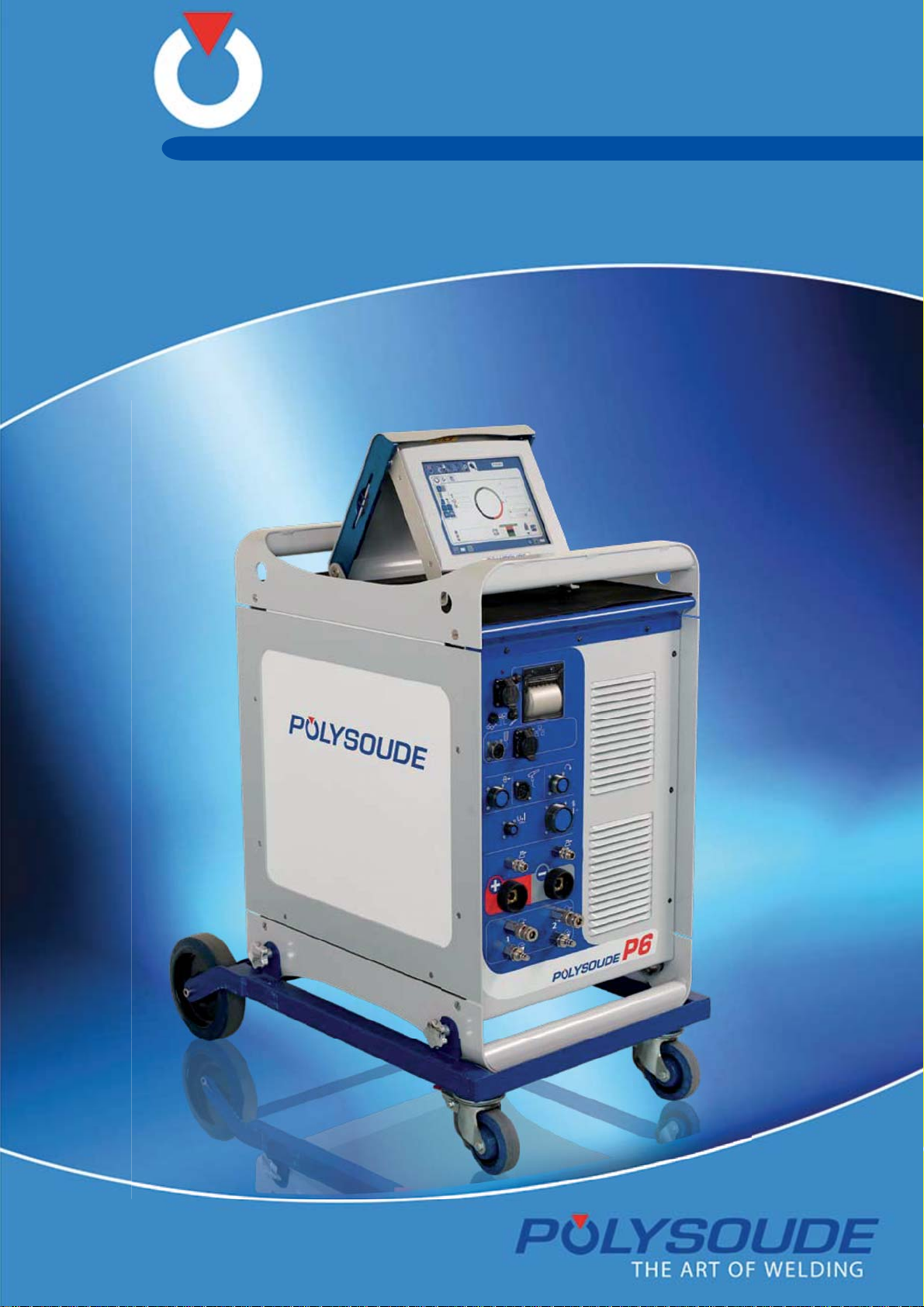
P6
TIG – With or without filler wire , AVC , OSC
Operating, maintenance and programming manual
Mobile power source
Page 2
P6
Product
Reference
Manual
Redactor
Revisions of the document
Rev. 0 Translation of the original document
Rev. 1 Up-dating due to new 6-axes version
Rev. 2
Rev. 3
Rev. 4 Update “Option commands mechanised equipment» 11/2011
Rev. 5
Rev. 6
Rev. 7 Addition chapter 4.5.3 Quick connector gas input
Rev. 8 Addition adapter manual torch and remote control 4 axis. 10/2012
Rev. 9
Rev. 10
Rev. 11 Addition manual torch adapter 0023000901 and ref remote control 04/2013
Rev. 12 Using the remote control to regulate the AVC 10/2013
Rev. 13 Update part list of the power source 01/2014
Rev. 14 Update touchscreen (09/2013) 02/2014
Rev. 15 Update part list remote control 06/2014
Rev. 16 Update : " Servicing" 08/2014
P6 mobile power source
0025059101/0025059103/0025059104/0025059105
PN-0509076
SBR
Update after a report of non-conformity and product evaluations;
sub-points § 7.2 and § 7.3 are added to the section “Adjustment of the
tachometer”
Update “Start cycle with restart” and “Fuses coolant pump control»
Update: FNCA 1201-039 and FNCA 1201-019 – Items on pages 56 to 59 –
Fuse § 6.2.2 and on page 46, Shunt for UHP welding heads on page 23,
gas values on page 20.
Addition of chapters: Connecting the measuring unit, Adjusting the measuring card, Compatibility of standard equipment.
Changes to pictures of the P6 power source.
Addition chapter Setting oxygen meter
Addition "Settings oxygen meter confi guration" "IP Address", updates
chapters "Making adjustments during a weld cycle" and "Error and codes
processing"
Modifi cation touchscreen controller, addition chapter remotes control on
board
01/2011
09/2011
02/2012
03/2012
06/2012
11/2012
03/2013
If this technical manual is to be printed, both sides of the page must be used to improve understanding and readability.
This manual must be delivered to users.
2-92 PN-0509076 Rev. 16
THE ART OF WELDING
Page 3

P6
Sommaire
1. Safety precautions ...................................................................................................... 5
1. 1. Arc welding hazards ......................................................................................................... 5
1. 2. Meaning of symbols .......................................................................................................... 5
1. 3. Recommendations ............................................................................................................ 6
1. 4. Danger in using a power source
1. 4. 1. Training of the operators ...................................................................................... 8
1. 4. 2. Access for maintenance and adjustments ............................................................... 8
1. 4. 3. Ergonomics ........................................................................................................ 8
1. 4. 4. Protection in the event of breakdown or failure of the equipment ............................... 8
1. 4. 5. Device for isolating energy sources ........................................................................ 9
1. 4. 6. Prevention of fi re and explosion ............................................................................9
1. 4. 7. Preventing release of gas and fumes ...................................................................... 9
1. 4. 8. Faultfi nding ........................................................................................................ 9
.................................................................................... 8
2. General information .................................................................................................. 10
2. 1. Applicable directives ....................................................................................................... 10
2. 2. Standards applied .......................................................................................................... 10
2. 3. Reference documents ..................................................................................................... 10
3. Introduction ............................................................................................................. 11
3. 1. The P4-P6 P6 HW series .................................................................................................. 11
3. 2. The welding heads ......................................................................................................... 16
3. 2. 1. The open welding heads ..................................................................................... 16
3. 2. 2. The closed chamber welding heads ...................................................................... 16
3. 2. 3. The tube to tubesheet welding heads ................................................................... 17
3. 2. 4. Accessories ...................................................................................................... 17
3. 3. Technical specifi cations of the P6 power source ................................................................. 18
3. 3. 1. Basic design ..................................................................................................... 18
3. 3. 2. Remote control unit 6 axis .................................................................................. 19
3. 3. 3. Remote control pendant 4 axis ............................................................................ 19
3. 4. Technical characteristics .................................................................................................. 20
4. Setting to work ........................................................................................................ 21
4. 1. Receipt of a P6 power source .......................................................................................... 21
4. 2. Installation .................................................................................................................... 22
4. 2. 1. Handling .......................................................................................................... 22
4. 2. 2. Placing in position ............................................................................................. 22
4. 2. 3. Connection to mains electricity supply .................................................................. 22
4. 2. 4. Connection with the gas supply ........................................................................... 24
4. 3. Connecting the acquisition module ................................................................................... 26
4. 3. 1. PC/Power source connection ............................................................................... 28
4. 3. 2. Equipment compatibility ..................................................................................... 29
4. 4. Setting to work .............................................................................................................. 30
4. 4. 1. Remotes control on board................................................................................... 30
4. 4. 2. Connection of the remote control unit ................................................................. 30
4. 4. 3. Connection of a gas cooled closed chamber welding head ....................................... 31
4. 4. 4. Connection of an open welding head of the MU type or a tube/tubesheet
welding head of the type TS or TP ....................................................................... 32
4. 4. 5. Connection of a liquid cooled closed chamber welding head ..................................... 34
PN-0509076 Rev. 16 3-92
THE ART OF WELDING
Page 4

P6
4. 4. 6. Connection of a liquid cooled closed chamber welding head with integrated
command buttons (MW 40-3, 65-3, 115-3, 170) .................................................... 35
4. 4. 7. Connection of a wire feed unit ............................................................................. 36
4. 4. 8. Connection of a closed chamber welding head equipped with tacheometry
(option) ........................................................................................................... 37
4. 4. 9. Connection of a manual torch with double command .............................................. 38
4. 4. 10. Detection of the welding head ............................................................................. 39
4. 4. 11. Detection of the «closed head» position ............................................................... 39
4. 4. 12. Oxygen meter option ......................................................................................... 40
4. 4. 13. Option commands mechanised equipment ............................................................ 41
4. 5. Description of controls .................................................................................................... 44
4. 5. 1. Front control and connection panel ...................................................................... 44
4. 5. 2. Rear connector panel ......................................................................................... 46
4. 5. 3. Quick connector gas input .................................................................................. 47
4. 5. 4. Remote control units 6 axis 0026169101 .............................................................. 47
4. 5. 5. Remote control pendant 4 axis 0026149101 ......................................................... 50
5. Operation of the power source P6 .............................................................................. 54
5. 1. Fundamental procedures ................................................................................................. 54
5. 1. 1. Switching on ..................................................................................................... 54
5. 1. 2. Automatic equipment detection ........................................................................... 54
5. 1. 3. Positioning a welding head on the workpiece ......................................................... 54
5. 1. 4. Wire setting ...................................................................................................... 54
5. 1. 5. Adjustment of the oscillation ............................................................................... 55
5. 1. 6. Adjustment of the gas fl ow ................................................................................. 55
5. 1. 7. Switching on the coolant pump manually ............................................................. 55
5. 2. Execution of a weld cycle ................................................................................................56
5. 2. 1. Safety precautions ............................................................................................ 56
5. 2. 2. Program selection ............................................................................................. 56
5. 2. 3. Simulation........................................................................................................ 56
5. 2. 4. Weld cycle ........................................................................................................ 56
5. 2. 5. Stop at end of the weld cycle .............................................................................. 57
5. 2. 6. Induced stoppage.............................................................................................. 58
5. 2. 7. Use of an USB key ............................................................................................. 58
5. 2. 8. Start cycle with restart ....................................................................................... 58
6. Servicing, maintenance and troubleshooting ................................................................. 59
6. 1. Servicing ..................................................................................................................... 59
6. 1. 1. Adjustments ..................................................................................................... 59
6. 1. 2. Adjustment of the tachometer............................................................................. 59
6. 1. 3. Cooling circuit ................................................................................................... 60
6. 1. 4. Printer ............................................................................................................. 61
6. 2. Maintenance and troubleshooting .................................................................................... 62
6. 2. 1. Replacement of fuses ......................................................................................... 62
6. 2. 2. Fuses coolant pump control ............................................................................... 62
6. 2. 3. Cooling circuit fi lter ........................................................................................... 63
6. 2. 4. Trouble shooting ............................................................................................... 65
6. 2. 5. Transfert of Log-fi les .......................................................................................... 69
6. 2. 6. Spare parts of the power source .......................................................................... 70
6. 2. 7. Spare parts for P6 remote control ........................................................................ 72
6. 2. 8. Spare parts of the touchscreen ........................................................................... 74
6. 2. 9. Electrical and electronic drawings ........................................................................ 76
7. APPENDIX ................................................................................................................ 79
7. 1. Error and codes processing .............................................................................................. 80
7. 2. List of programmed welding parameters ............................................................................ 81
8. End of service life, recycling the equipment .................................................................. 85
9. Returned equipment form .......................................................................................... 87
4-92 PN-0509076 Rev. 16
THE ART OF WELDING
Page 5
P6
Safety precautions1.
Note: Protect yourself and others from injury - read and follow these instructions
Arc welding hazards1. 1.
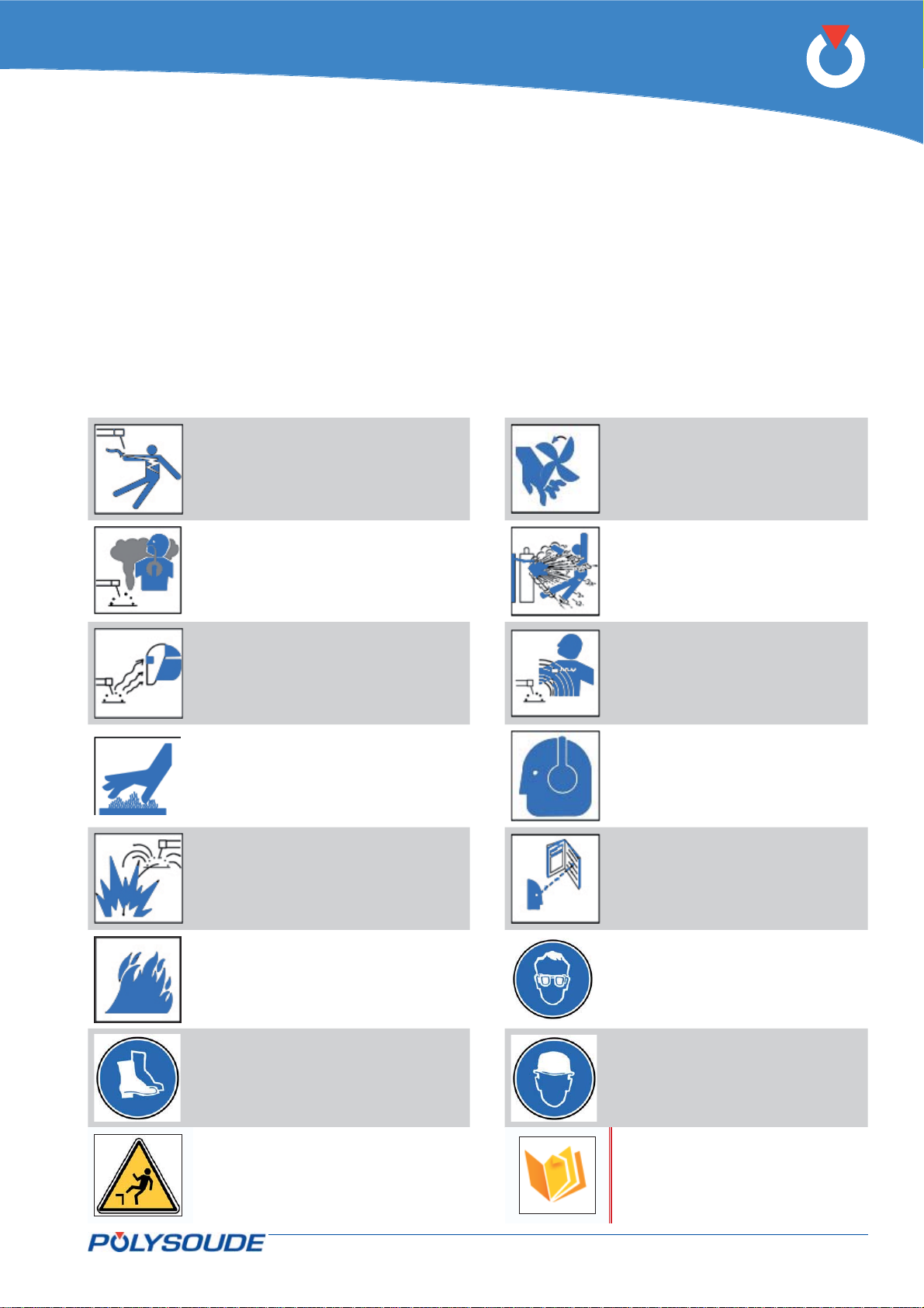
The following symbols are used in the text to draw your attention and to identify risks and dangers.
When you see a symbol, consult the safety rules in the Recommendations chapter below.
Only qualifi ed staff are permitted to undertake installation, use, maintenance and repair work on a power
source.
When using the equipment, keep away everybody who is not working with the installation.
Meaning of symbols1. 2.
Risk of electric shocks
Risk of severe injuries
caused by moving parts
Risk of fume or gas inhalation Risk of explosion
Risk of eye or skin burns
caused by radiation
Warning: hot parts – Risk of
burns
Risk of eye or skin burns
caused by fl ying sparks
Risk caused by magnetic
fi elds
Danger caused by noise
Read the instructions
Risk of overheating, fi re Eye protection mandatory
Foot protection mandatory Helmet mandatory
Refer to the recommenda-
Risk of falling.
tions below in order to take
the necessary precautions
to avoid any hazard.
PN-0509076 Rev. 16 5-92
THE ART OF WELDING
Page 6

P6
Recommendations1. 3.
Risk of electric shocks
Electrical parts are the electrode, the weld circuit, the
supply circuit and the internal circuits, the fi ller wire
and metal parts in contact with it, the wire feeder
unit and the wire feeding mechanism. Any contact
with these parts can cause an electric shock if the
installation is connected to the mains supply.
Circumstances increasing the risk of electric shocks:
humid environment, working on a conducting surface,
poor earth connection, poor maintenance of equipment, unsafe working conditions.
To prevent risks:
Avoid any contact with energised wire spools.•
Inspect water cooled torches regularly to detect •
leakage, take care to avoid condensation.
Do not wind the cables around your body.•
Make sure that the electrode is not energised •
when changing it.
Before any maintenance or repair work or if •
equipment is not in use, disconnect the equipment from the mains supply.
Wear gloves, clothes, aprons and safety shoes •
that are dry and without holes.
Isolate yourself from the part and from earth •
using carpets or other suitable insulating materials if carrying out welding on metal surfaces or
structures.
The equipment must be installed and earthed as •
specifi ed in the operating manual and in nation-
al, local and municipal codes of practice.
The current return cable must be fi xed correctly •
(clean surface, solid clamping as close as possible to the weld area).
Cables that are damaged, worn or without •
sheathing, the wrong size or badly assembled
must not be used. They must be replaced immediately.
The welding set must be properly earthed.•
Use a separate cable if the workpiece must be •
earthed.
Appropriate connectors must be used.•
Make sure that the open circuit voltage limited to
80 Vac rms or 113 Vdc (voltage needed for arc
ignition). Maximum value for plasma cutting power
sources: 500 V.
Risk of fume or gas inhalation
During welding, fumes and gases are released which
are dangerous to your health. Avoid inhaling fumes.
Sources of fumes and gases: base metal: basic
material, fi ller metal, weld coating (fl ux) with coated
rod electrodes, shielding gas, solvents and materials
covering the workpiece.
To prevent risks:
Use breathing apparatus such as fi lter masks, •
forced ventilation masks, air-shield masks, disposable masks.
Avoid chlorinated solvents.•
Dry the workpieces thoroughly before welding.•
Do not work alone!•
Control fumes and gases at source.•
Remove paint, oil and any other coatings from •
the surface.
Risk of eye or skin burns
caused by radiation
Radiation from the welding arc can cause eye and
skin burns.
Risk identifi cation: exposure to radiation emitted
from the arc generating intense visible and invisible radiation (ultraviolet and infrared); refl ections of
radiation when welding metals such as aluminium or
stainless steel; blinding glare, sparks, stings caused
by the tungsten electrode tip.
To prevent risks:
Wear gloves or leather sleeves to protect hands •
and forearms.
Wear an apron or gaiters to protect the legs and •
knees to upper foot.
Wear a mask (strapped to the head, handheld or •
electronic) or goggles equipped with a suitable
fi lter.
Use shielding curtains to protect staff working •
nearby.
Wear a scarf around your neck and close the col-•
lar of your clothing.
6-92 PN-0509076 Rev. 16
THE ART OF WELDING
Page 7
P6
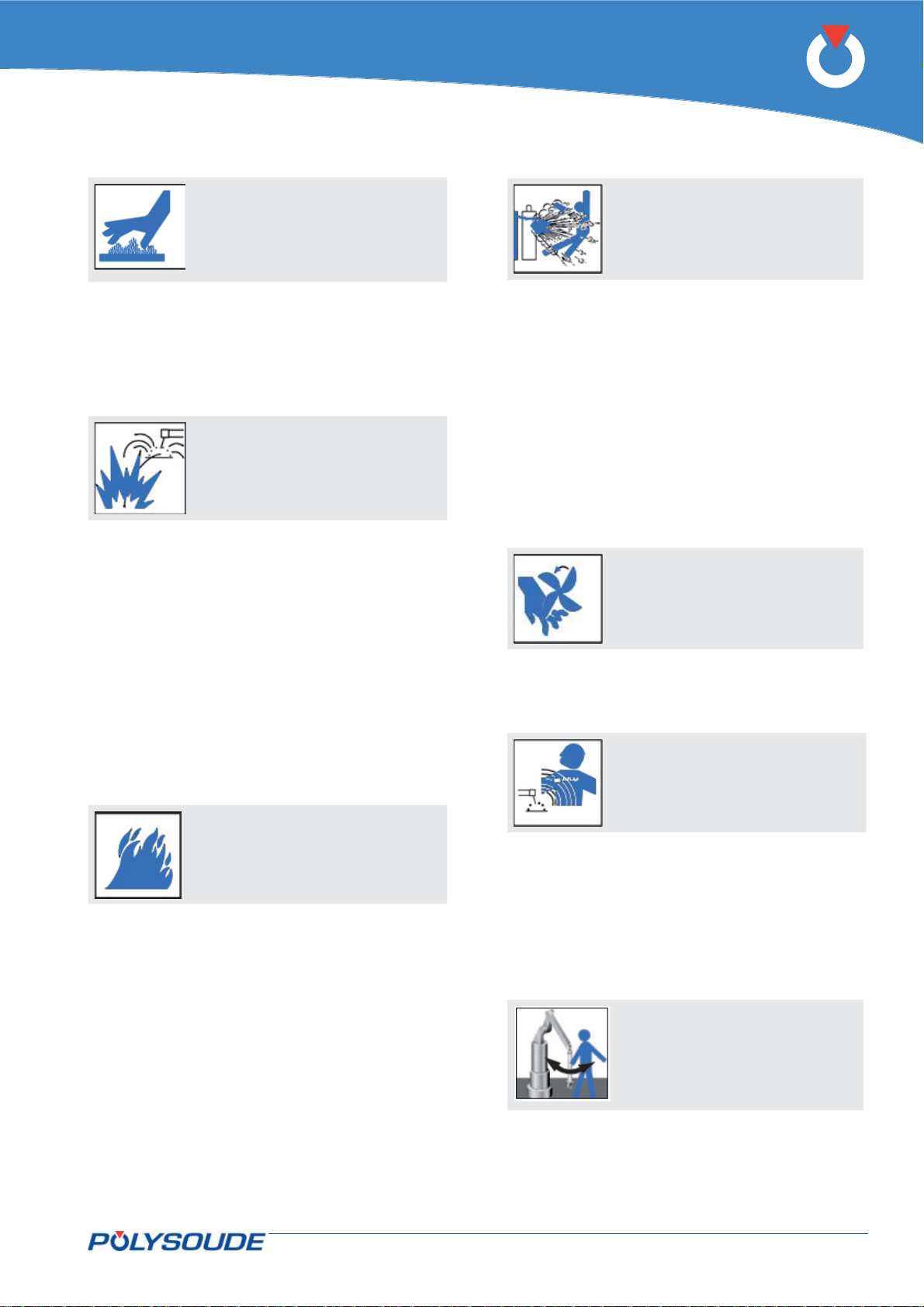
Warning: hot parts – Risk
of burns
Do not touch welded or torch-cut parts with bare •
hands. If you have to handle them use suitable
tools and/or wear thick and insulating welding
gloves to prevent burns.
Welded parts must cool down before handling or •
further weld operations.
Risk of eye or skin burns
caused by fl ying sparks
Wear gloves or leather sleeves to protect hands •
and forearms.
Wear an apron or gaiters to protect the legs and •
knees to upper foot.
Wear a mask (strapped to the head, handheld or •
electronic) or goggles equipped with a suitable
fi lter
Use shielding curtains to protect staff working •
nearby.
Wear cotton or woollen clothes with long sleeves, •
without oil or lubricant marks - avoid synthetic
fabrics.
Wear a scarf around your neck and close the col-•
lar of your clothing.
Wear safety boots made for welders.•
Risk of explosion
These risks are caused by using and handling gas
bottles and by fl ying sparks.
Never use damaged gas bottles.•
Stock the gas bottles in a well-ventilated room, •
allowing access only to authorised staff.
The temperature limit of 55 °C must be re-•
spected for the storage and use of gas bottles.
Separate clearly marked empty gas bottles •
from new ones.
Protect gas bottles from extreme temperatures •
(freezing, sun, sparks, etc.).
Inspect connections and hoses regularly.•
Use shielding curtains.•
Risk of severe injuries
caused by moving parts
•
Never place your hands near a fan or other •
moving parts.
Keep all safety devices closed or in safe mode.•
Risk caused by magnetic
fi elds
Risk of overheating, fi re
Keep the installation in good condition, especially •
the supply cables and the current return cable.
Keep a minimum distance of 6 m between the •
welding equipment and any greasy, explosive or
dusty substance.
Use shielding curtains to protect staff working •
nearby.
The distance between the brain and the welding
circuit is a very important parameter.
Never wind cables around your body or, even •
worse, over your shoulders.
Make it known if you have been fi tted with •
a pacemaker. Possible interference must be
prevented by special measures in co-ordination
with a physician.
The operator must ensure
that no one is exposed to
dangerous areas
PN-0509076 Rev. 16 7-92
THE ART OF WELDING
Page 8
P6
Danger in using a power source1. 4.
Work or maintenance procedures described in this manual may be accompanied by dangers or risks. Such
procedures are indicated by the following pictograms.
Risk or situation with danger of serious injuries or even
death.
Operating procedures and settings for preventing damage to equipment and special instructions will be marked
by the headings Remark or Note.
Training of the operators1. 4. 1.
Behind the power source, close to the Power On
switch, this label states that it is advisable to read
the instruction manual. An instruction manual is
delivered to the client. A copy (all rights reserved)
of this manual MUST be given to the user personnel:
operators, setters, servicing personnel, etc. They
must have appropriate qualifi cation for the tasks
they have to do, in accordance with the rules for new
employees governed by the French Labour Code.
Access for maintenance and adjustments1. 4. 2.
Access to the upper parts of the equipment for adjustment or servicing of units which are out of reach
of the operator must be undertaken using a stable
method, such as a ladder or stepladder, in accordance with current safety standards.
It is strictly forbidden to climb up the equipment by
supporting oneself on pipework, a desk, a console or
bracket for the cycle control buttons, etc.
Ergonomics1. 4. 3.
SignsA.
Elements used for the signs, especially safety-relevant parts (e.g. colours of push-buttons and indicator lights — refer to NF X 08 003, NF EN 60073, NF
EN 894-1, ISO 369) must not be modifi ed in any
circumstances (inversion of the colours). Indicator
lights or buttons with whose colours become indiscernible due to aging or wear MUST be replaced.
Adequate illumination of work areasB.
Generally, welding equipment does not require the
use of spot lights, but rather a medium surrounding
level of illumination. The user must take all necessary
measures to ensure that the workshop is equipped
with suitable lighting (avoiding shadow areas and
glare) so that the operators do not suffer from excessive tiredness or inconvenience.
Protection in case of breakdown or failure of the
equipment
If no welding operations are carried out, the staff
must protect themselves by activating appropriate
separation devices.
Protection in the event of breakdown or failure 1. 4. 4.
of the equipment
During operations other than welding, personnel
must protect themselves by operating the isolation
device appropriate for the operation they have to
perform.
8-92 PN-0509076 Rev. 16
THE ART OF WELDING
Page 9
P6
Device for isolating energy sources1. 4. 5.
Provision of shut-off devices
Isolation devices (electrical, hydraulic, pneumatic...)
are mandatory. If they do not form part of the POLYSOUDE supply (as is the case with portable installations), they MUST be provided by the user who must
install them at his cost and responsibility.
Operation of shut off devices
In accordance with the stipulations in the manufacturer’s technical manual, before actioning shut-off
devices (isolation of equipment from its source of
power), personnel must make sure that neither they
not any third party is in danger.
Prevention of fi re and explosion1. 4. 6.
Welding equipment must not be used on premises
where infl ammable, volatile or explosive products
are present. In no circumstances is the P6 power
source to be used to thaw pipework.
Preventing release of gas and fumes1. 4. 7.
It is the user’s responsibility to assess:
inconvenience or unhealthy conditions inside his •
workshop and to take the necessary measures to
apply this clause.
Protection against radiation from electric arcs.•
Safety instructions and protective arrangements •
must conform to NF EN 166 and NF EN 169.
Faultfi nding1. 4. 8.
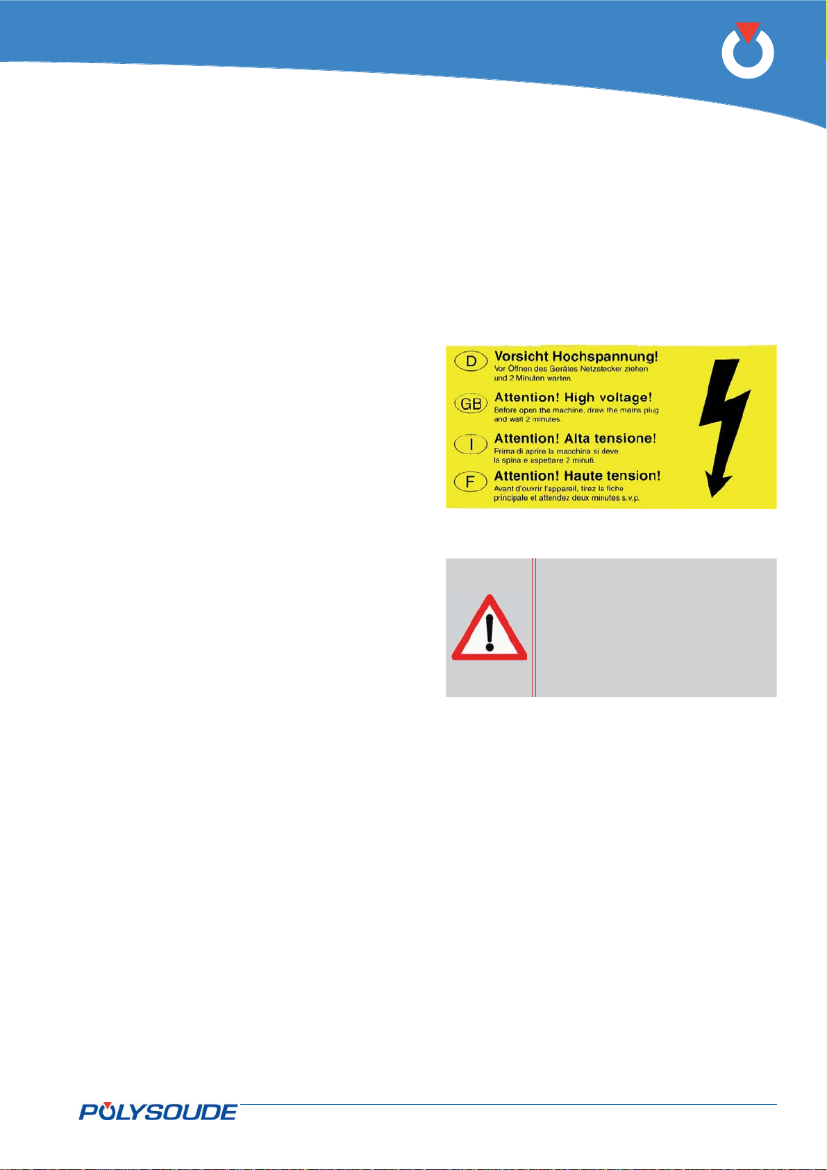
Only a qualifi ed electrician is authorised to inspect,
test, adjust or repair electric or electronic equipment.
Before any maintenance work can be carried out or
an instrument is connected to a circuit, the mains
supply must be disconnected and a waiting period of
2 minutes must have elapsed. These instructions are
specifi ed on the label at the right side of the power
source.
Always check that no voltage
is present even if the installation has been disconnected from the mains. A capacitor can store its voltage for
a long time after it has been
disconnected from the power
source.
Never shunt or remove the safety devices or interlocks installed to protect personnel.
Never stand on a wet or humid fl oor during inter-
vention on electric or electronic devices. It is essential to avoid any leakage of liquids inside electric or
electronic equipment.
Never use volatile or fl ammable solvents in the
workshop. The electric arc could ignite the vapours
or fl ammable liquids.
During faultfi nding and maintenance work on electri-
cal equipment, take off any jewellery (rings, watches, bracelets, etc.). Insulating shoes must be worn
when the situation requires it.
PN-0509076 Rev. 16 9-92
THE ART OF WELDING
Page 10
P6
General information2.
Applicable directives2. 1.
2004/108/EC Electromagnetic compatibility
2006/95/EC Electrical equipment designed for use within certain voltage limits
Standards applied2. 2.
EN 60974-1 Arc welding equipment — Part 1: Welding power sources
EN 60974-10 Arc welding equipment — Part 10: Electromagnetic compatibility (EMC) require-
ments.
Reference documents2. 3.
PN-0908080 User manual for touchscreen
10-92 PN-0509076 Rev. 16
THE ART OF WELDING
Page 11

P6
Introduction3.
The P4-P6 P6 HW series3. 1.
The P6 belongs to a new series of universal and functional power sources for orbital TIG welding. The complete
realisation of a weld is the result of applying a WP (Weld Procedure), containing one or more programs when
several passes are necessary, documentation for preserving information about the weld, such as preparation
of the tubes, electrode diameter and grinding angle, workpiece/ electrode distance, wire diameter and feeding
angle etc.
The WP also assists the operator fi nding a successful solution of the weld problem. Particular features of the
power source P6 are:
The welding sequences are completely programmable in the operator’s language.•
The handling is simple and easy to learn because of the intuitive programming concept.•
Built-in library of WPs for fast weld parameter search.•
A measurement data acquisition system.•
An integrated printer for archiving and documentation to ISO 9000.•
WPs can be stored on internal memory or on a USB key.•
Modern power sources using inverter-technology.•
Mechanised welding can be carried out with all the convenience of the P4-P6 series power sources.•
Features of the P4-P6 P6 HW power sources:
DC or pulsed weld current can be supplied.•
Continuous or pulsed movement and continuous or pulsed wire feeding in synchronisation with the weld •
current.
PN-0509076 Rev. 16 11-92
THE ART OF WELDING
Page 12
P6
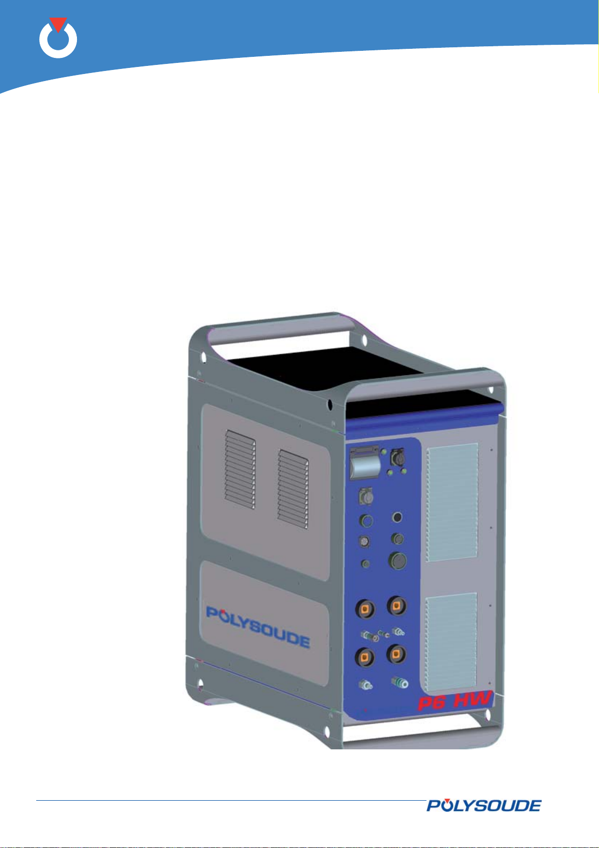
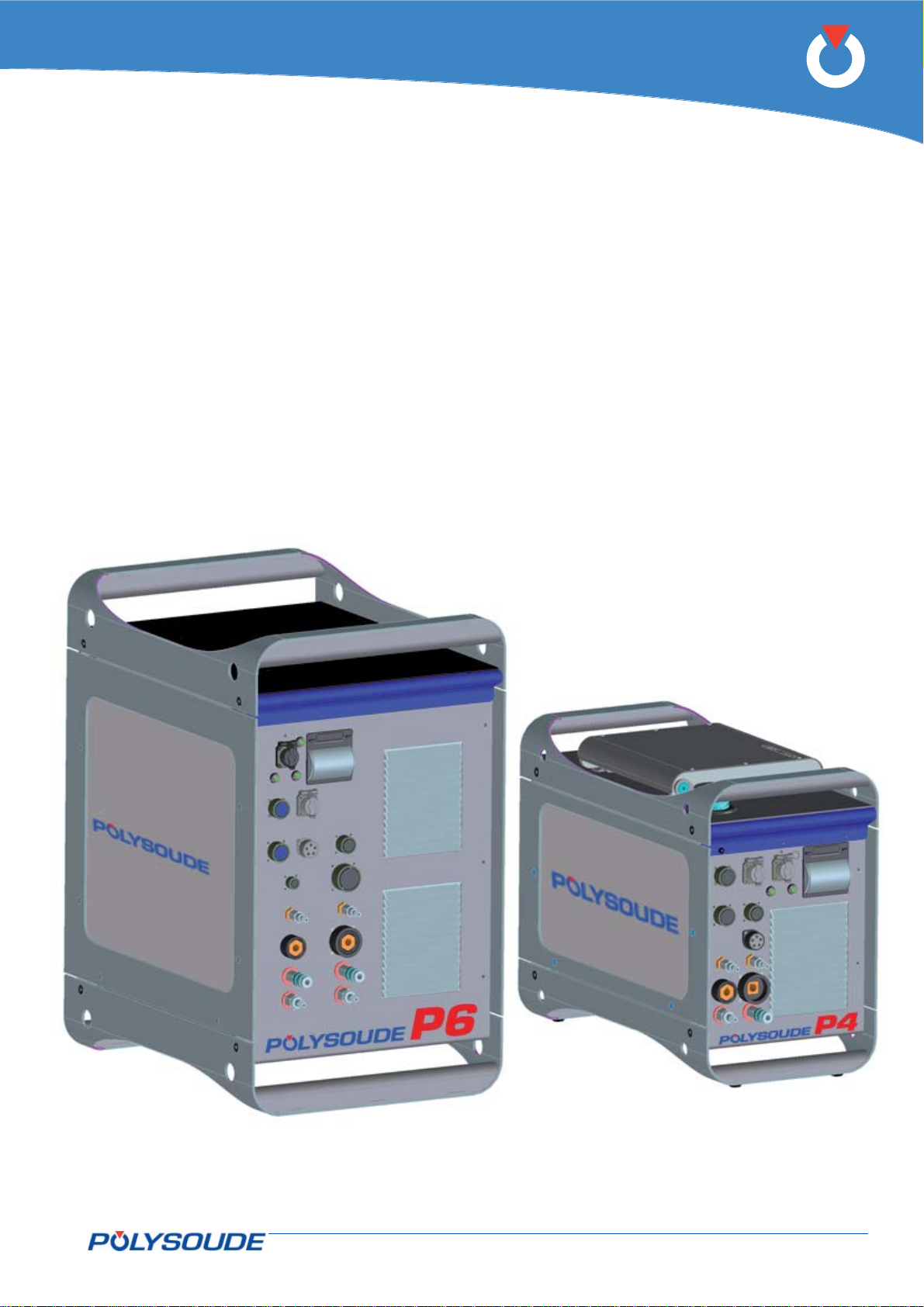
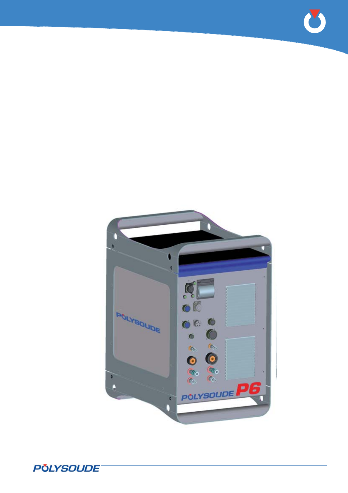
P6 HW
520 A mobile power source.
Ideal for high current, hot-wire welding.
Fig. 3.1 - P6 HW power source
12-92 PN-0509076 Rev. 16
THE ART OF WELDING
Page 13
P6
P6
300 A mobile power source.
Ideal for prefabrication work.
P4
170 A mobile power source.
Ideal for mobile use on site.
Fig. 3.2 - P6 power source
PN-0509076 Rev. 16 13-92
THE ART OF WELDING
Fig. 3.3 - P4 power source
Page 14

P6
P6 CW orbital power source
P6 CW - 400/415 V ± 10%, three-phase, 50/60 Hz – Basic version
(including torch rotation control) with printer 00 2505 9101
P6 CW - 400/415 V ± 10%, three-phase, 50/60 Hz (4 axes) – Basic version
(including torch rotation control) with touchscreen, wire feeder control,
printer and remote control pendant (4 axes) 00 2505 9103
P6 CW - 400/415 V ± 10%, three-phase, 50/60 Hz (5 axes) – Basic version
(including torch rotation control) with touchscreen, wire feeder control,
printer, remote control pendant (6 axes) and arc voltage control (AVC) 00 2505 9104
P6 CW - 400/415 V ± 10%, three-phase, 50/60 Hz (6 axes) – Basic version
(including torch rotation control) with touchscreen, wire feeder control,
printer, remote control pendant (6 axes), arc voltage control (AVC)
and oscillation control (OSC) 00 2505 9105
14-92 PN-0509076 Rev. 16
THE ART OF WELDING
Page 15
P6
PN-0509076 Rev. 16 15-92
THE ART OF WELDING
Page 16
P6
The welding heads3. 2.
These power sources support several of the Polysoude series welding heads.
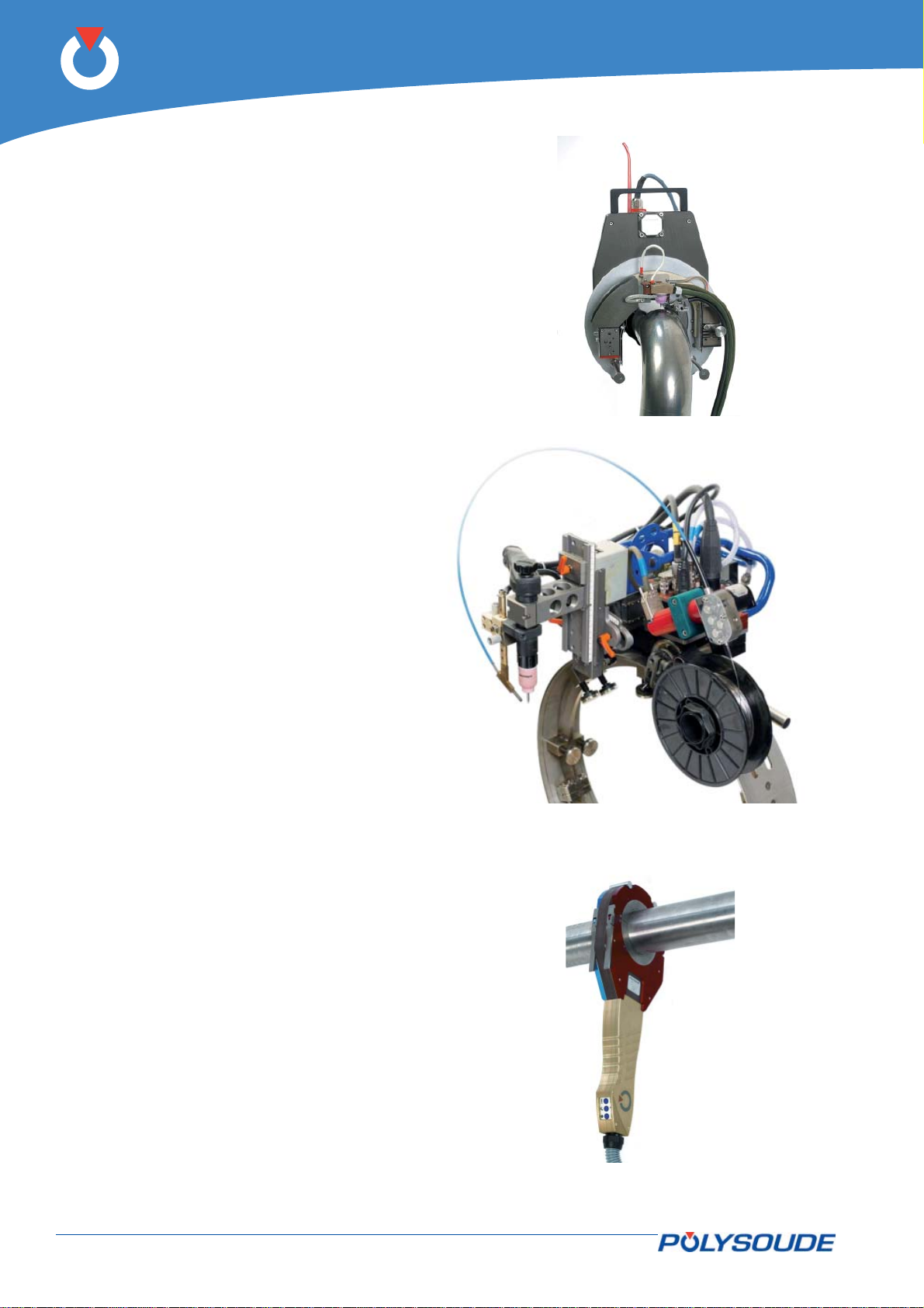
The open welding heads3. 2. 1.
MU IV type (Fig. 3.4) for standard or special ap-•
plications. Modular design. Weldheads designed
for butt welding pipes, with or without fi ller wire.
Polycar welding head (Fig. 3.5) to weld large •
diameter pipes.
Fig. 3.4 - MU IV welding head
Fig. 3.5 - Polycar welding carriage
The closed chamber welding heads3. 2. 2.
MW (Fig.3.6) when high productivity is required. •
High duty cycle due to water cooling. Adaptor
kits available for welding of accessories (elbows,
fl anges, valves, connections, etc.).
Sentry UHP for the demands of ultra high pu-•
rity welding. Welding head with closed chamber
designed for but welding thin pipes without fi ller
wire. It ensures high quality welds and its compact design enables it to be used in areas with
restricted access.
HD when the access to the weld area is restricted.•
K for applications calling for the best shielding •
gas protection.
Fig. 3.6 - MW welding head
16-92 PN-0509076 Rev. 16
THE ART OF WELDING
Page 17
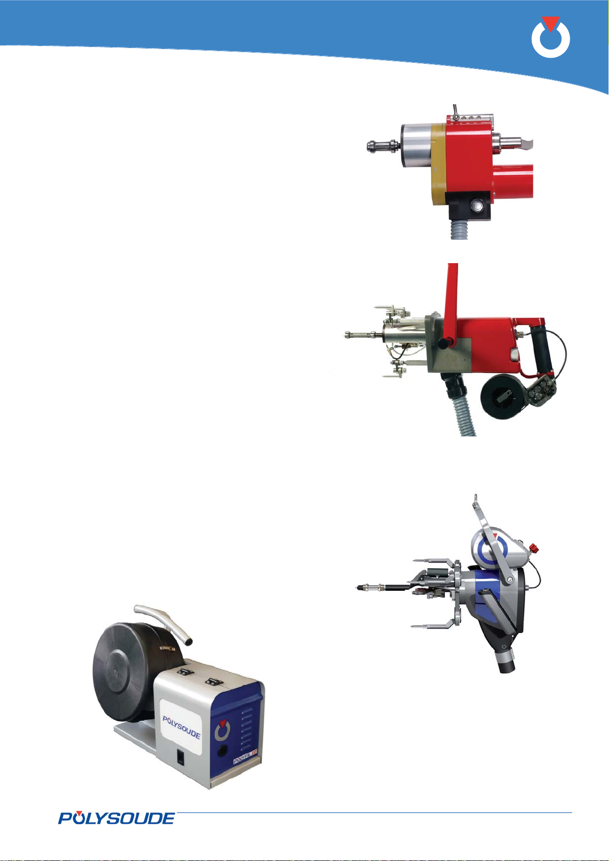
The tube to tubesheet welding heads3. 2. 3.
TS welding heads to meet sought-after produc-•
tivity and quality requirements.
TS 25, standard welding head for tube to tube •
sheet.
Closed welding head, designed for slightly protruding or fl ush tubes.
P6
TS 34 (Fig.3.7), standard welding head for tube •
to tube sheet particularly designed for high duty
cycle applications.
Closed welding head for slightly protruding or
fl ush tubes.
TS 2000 (Fig.3.8) and TS 8/75 (Fig3.9), stand-•
ard welding head for tube to tubesheet applications.
Open weldhead for protruding, fl ush or recessed
tubes.
Accessories3. 2. 4.
POLYFIL-3 (Fig.3.10) external wire feeder.
Wire feeder with four-roller linear drive system to
minimise wire deformation and damage to wire
surface.
Fig. 3.7 - TS 34 welding head
Fig. 3.8 - TS 2000 welding head
Fig. 3.9 - TS 8/75 welding head
Fig. 3.10 - Polyfi l-3 wire feeder
PN-0509076 Rev. 16 17-92
THE ART OF WELDING
Page 18
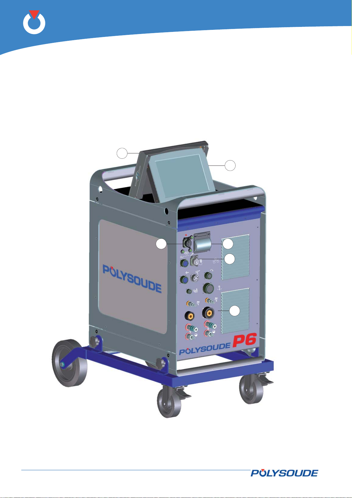
P6
Technical specifi cations of the P6 power 3. 3.
source
Basic design3. 3. 1.
The welding set contains the power source, all control
electronics and the torch cooling. All connections are
made on a connector panel situated at the front of
the power source.
1
The front panel also supports the printer and connections for the USB key and the RJ45 link for connecting a PC.
There is a touchscreen mounted on top of the power
source for programming and monitoring of the weld
cycles.
The power source is fi tted with a 2-metre long power
supply cable.
2
Fig. 3.11 - Description of P6 power source
5
3
4
6
1 Protection for programming screen 4 RJ45 connection
2 Screen and touchscreen (option) 5 USB connection
3 Printer (option) 6 Connection panel
18-92 PN-0509076 Rev. 16
THE ART OF WELDING
Page 19
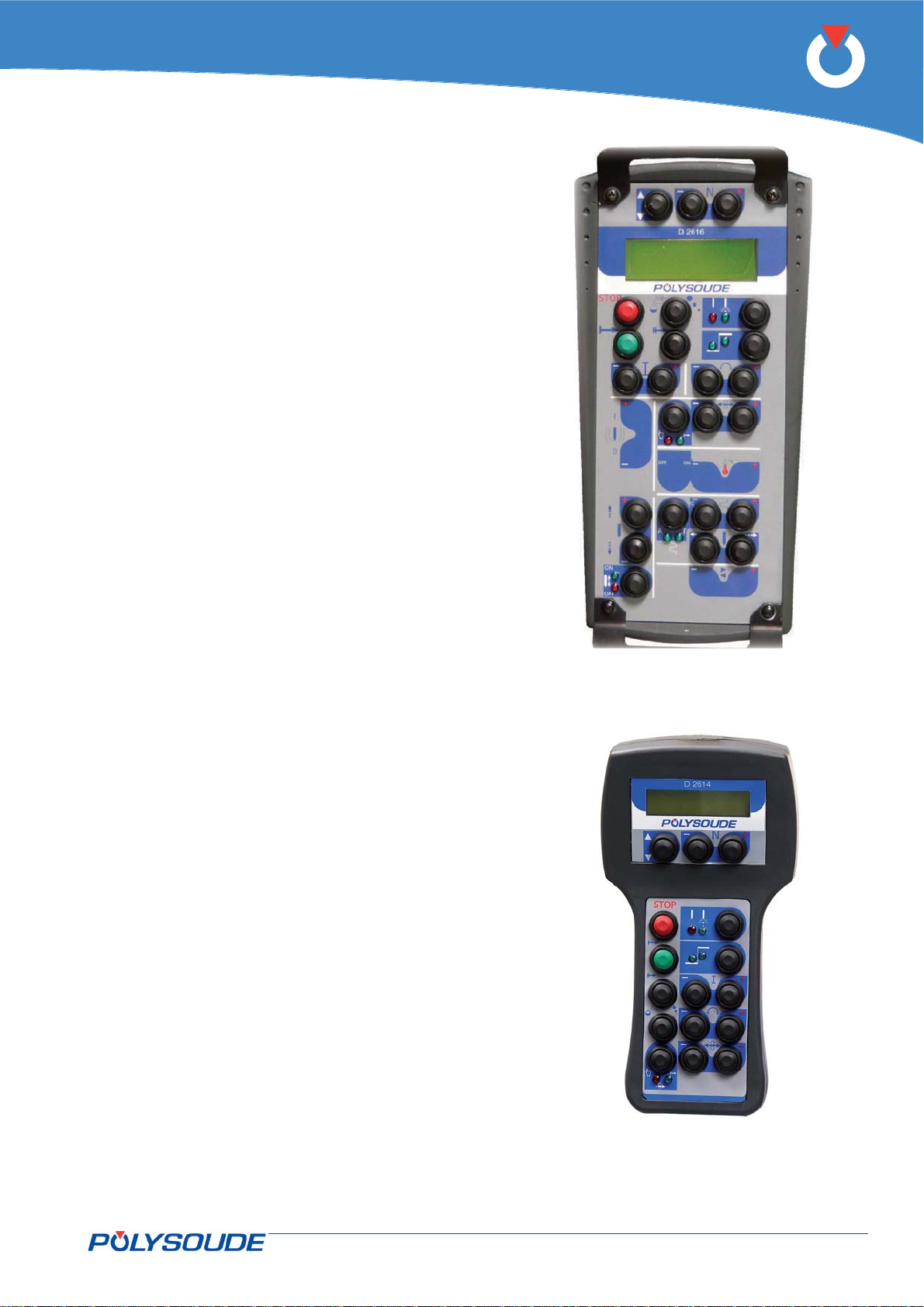
Remote control unit 6 axis3. 3. 2.
All functions and parameters can be monitored and
changed by the remote control unit (option):
Positioning welding heads and wire feeders.•
Starting and stopping weld cycles.•
Selecting WPs and programs.•
Simulating weld programs.•
Minor modifi cations during a weld cycle.•
Shielding gas test.•
Manual starting of the cooling pump.•
P6
Remote control pendant 4 axis3. 3. 3.
All operations and parameters can be controlled by
the remote control pendant:
Set up of Welding heads and wire feeders.•
Start and stop of weld cycles.•
Selection of WPs and programs.•
Simulation of weld cycles without arc.•
Parameter modifi cations during a weld cycle.•
Shielding gas test.•
Manual start of the cooling pump.•
Fig. 3.12 - P6 remotes control unit
PN-0509076 Rev. 16 19-92
THE ART OF WELDING
Page 20
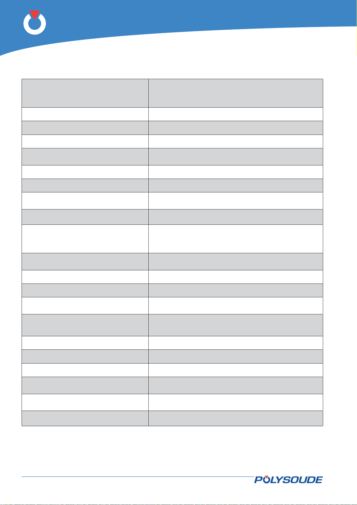
P6
Technical characteristics3. 4.
Threephase + earth
Mains power source
Current consumption 13 A (400 V)
Open circuit voltage 100 V
Insulation class F (E for multivoltage option)
400 V/415 V ± 10 %
50 or 60 Hz
Multivoltage option 200 V - 480 V ± 10 %
Protection class
IP 23 (with touchscreen closed)
IP 20 (with touchscreen open)
Weld current range 5 to 300 A
Current regulation ± 1 % if I > 100 A and ± 1 A if I ≤ 100 A
Duty cycle
Pulsed current range
300 A at 60 %
240 A at 100 %
300 A range: 5 to 300 A
Time period from 10 to 3300 ms
Welding head rotation
Movements monitored
Wire feeder
Height of arc - AVC - (option)
Oscillation - OSC- (option)
Speed accuracy
± 1 % at Vp ≥ ¼ V
± 2 % at Vp < ¼ V
(Vp = programmed speed)
max
max
Gas monitored Torch gas, second gas (option)
Source cooling Forced ventilation
Weld torch cooling
Cooling liquid in closed loop with safety device (2nd circuit as
option)
Continuous display of the power source output voltage and
Display of actual magnitudes during cycle
the weld current (if remote control unit or touchscreen option
present)
Number of stored WPs 200 maximum
Sectors per program 99 maximum
Archiving and loading on USB-key
Overall dimensions
Weight
630 x 470 x 790 mm (L x D x H)
630 x 470 x 1110 mm (Multivoltage version)
(with cooling liquid, touchscreen and printer)
76 kg
160 kg in multivoltage version with carrier
Standards EN 60974-1 et EN 60974-10
The EMC classifi cation to EN 55011 (EN 60974-10) has been executed to class A requirements.
The heating tests have been carried out at ambient temperature. The duty cycle at 40 °C has been determined
by simulation.
20-92 PN-0509076 Rev. 16
THE ART OF WELDING
Page 21
3
Setting to work4.
Receipt of a P6 power source 4. 1.
The P6 power source is delivered in packaging consisting of a box and protection, etc. This original packaging must be kept and used each time the power
source is transported, in order to avoid damage.
When the power source is not in use, it must be
stored on a suitable support and protected against
impact damage (even when in its packaging).
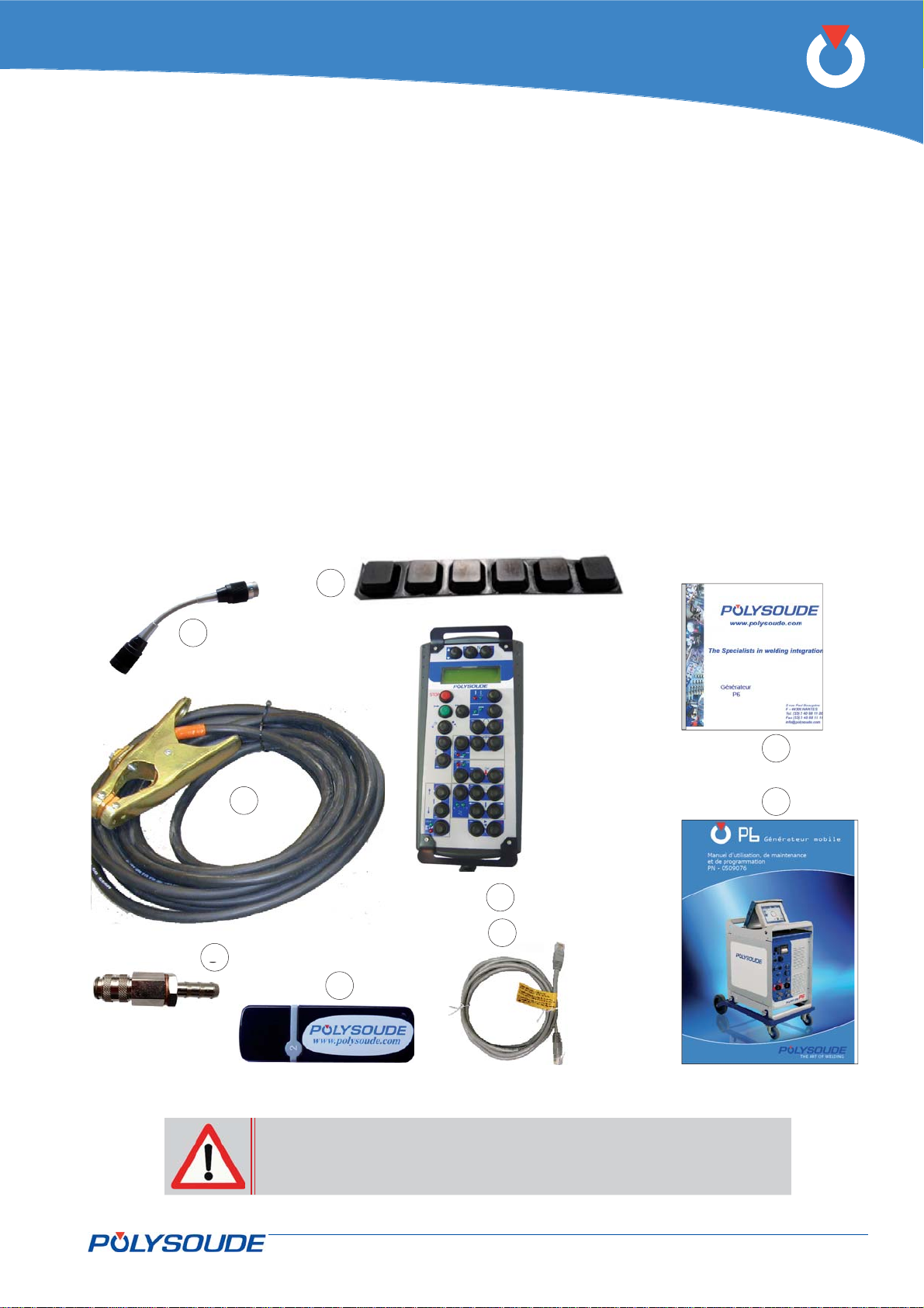
In the package you will fi nd:
A remote control unit D2616, 6-axes version •
(Fig.4.1 – Item 1b (option).
A 9 m long earth cable (Fig.4.1 – item 2).•
A gas hose connector (3 hose connectors if the •
optional second gas has been ordered) (Fig.4.1 –
Item 3).
P6
This user manual (Fig.4.1 - Item 4).•
A USB Key (Fig.4.1 – Item 5).•
The installation CD ROM (Fig.4.1 – Item 6).•
A RJ45 cross-coupled cable to connect the PC with •
the power source (Fig.4.1 – Item 7).
A adapter manual torch ref. 0023000901 (Fig.4.1 •
- Rep.8).
Pad set anti-slip (Fig.4.1 - Rep.9).•
9
8
6
2
1
7
3
5
4
Fig. 4.1 - Accessories supplied with the power source P6
If a PC is used you must use the RJ45 cable supplied with the power
source. Failure to use this cable may result in hazards for the user.
Polysoude declines to accept any liability unless the PC/Power source connection is made with the RJ45 cable.
PN-0509076 Rev. 16 21-92
THE ART OF WELDING
Page 22
P6
Installation4. 2.
Handling4. 2. 1.
To move the P6 power source use the handles provided.
Never pull on any cables or pipework. If moving
using a fork-lift truck take care to ensure stability.
For lifting, the slings must be attached at the four
holes in the upper arch so as to distribute the load
evenly with a maximum angle of 15° with respect to
the vertical.
Placing in position4. 2. 2.
Make sure that the system is placed fl at, on a stable
surface.
If the equipment is used on a slope, take care to
ensure that the power source does not topple over.
Openings are provided for ventilation of the power
source. When installing it allow a minimum distance
of 30 cm between these openings and any surface.
The power source is designed to protection class
IP23S; it can be stored outside but must not be used
without protection during precipitation.
Connection to mains electricity supply4. 2. 3.
All connections must be made by
a qualifi ed technician in accor-
dance with the safety instructions
quoted in the safety chapter.
Note: The operating company is responsible for the
installation and the use of the arc welding equipment conform to the manufacturer’s instructions. If
electromagnetic interference occurs, the operating
company must solve the problem with the support of
the manufacturer (extract of the standard EN 6097410 2008 – annex A).
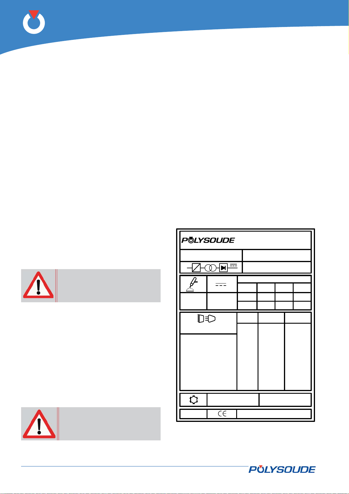
Z.I. DU BOIS BRIAND 2 rue P.BEAUPERE
TYPE:
3~
f1
P6
f2
44316 NANTES CEDEX 3 FRANCE
EN 60974-1
Made in France
N°:
EN 60974-10
5A / 10,2V - 300A / 22V
60%
U0 = 98V
X
I
2
U
2
300A
22V
100%
240A
19.6V
U1
3 ~
General
The P6 power source is connected to the mains power
supply with a cable containing 3 conductors + earth.
A 3.5 m long cable is provided for this purpose. It is
essential to connect the earth conductor in order to
ensure the safety of the operators.
50/60Hz
220V
240V
400V
Refer to the power source rating plate for the
currents consumed for different mains voltages. For
example, for a 400 V mains supply a 16 A protection is required.
440V
480V
P 1l/min = 0,5 kW
To ensure safety of operators,
the protective (earth) conductor
must be connected.
22-92 PN-0509076 Rev. 16
IP 23S
Fig. 4.2 - Rating plate of the P6 power source
I1 max I1 e
208V
37.5A
230V
34.4A
380V
20.6A
415V
18.8A
460V
17.2A
THE ART OF WELDING
39.6A
36.0A
21.8A
20.0A
18.0A
25A41.2A200V
24A
23A
22A
21A
13.5A
13A
12A
11.5A
11A
10.5A
P max = 0,5 MPa
Page 23
Power source for connecting to 400/415 V
In your installation, you must provide «inductive load
fuse protection (motor rated) with a 16 A rating.
P6
Multi-voltage power source
In your installation, you must provide «inductive load
fuse protection (motor rated). For the fuse rating
please refer to the I1rms current on the rating plate
as a function of the mains voltage.
Mains coupling
Before proceeding on any electrical part, make sure the machine is not connected to the
electric supply and the voltage
corresponds to one of the values
mentioned in the table
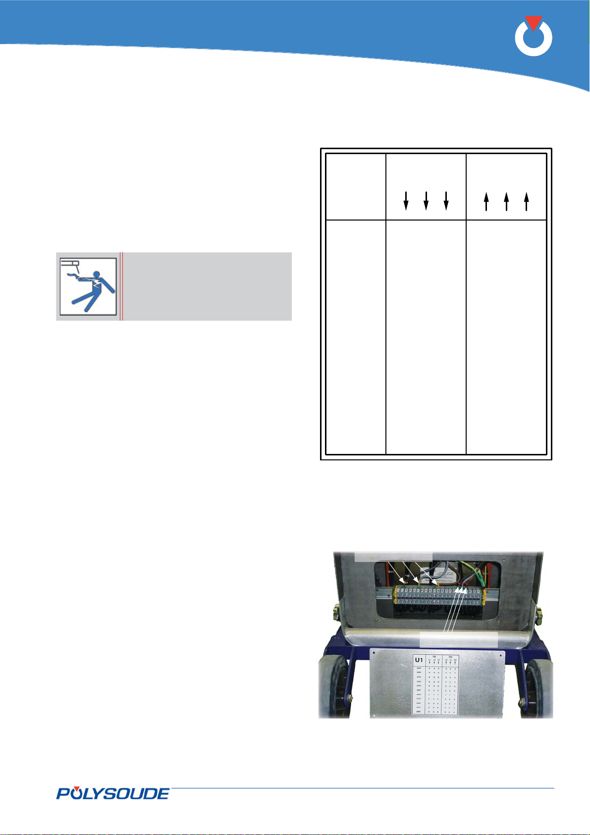
For a P6 fi tted with the multi-voltage kit the trans-
former must be coupled up before the mains is
connected. The table in Fig. 4.3 gives the position of
the coupling links as a function of the mains voltage.
The power sources are coupled up for 480V when
they leave the factory.
In order to connect the transformer, open the access
hatch at the rear of the multi-voltage module in the
bottom area of the power source.
Up Us
U1
200V Z Z Z
208V Y YYAAA
220V B B B
230V
240V X XXBBB
380V Z ZZCCC
400V Y YYCCC
415V X XXCCC
440V Z ZZDDD
460V Y YYDDD
480V X XXDDD
L1 L2 L3
AAA
BBBYYY
U1 W1V1
ZZZ
Fig. 4.3 - Transformer coupling
Up connections
Us connections
Fig. 4.4 - Layout of coupling terminal block
PN-0509076 Rev. 16 23-92
THE ART OF WELDING
Page 24

P6
Connection with the gas supply4. 2. 4.
The connection is made on the rear connector panel of the power source using the connectors delivered with
the machine.
On the gas source outlet (gas cylinder or manifold) litre fl owmeters should be used (see § 4.2.4 Spare parts) for
the fl owmeter reference. Before making any connections, briefl y open the gas valve to expel any impurities.
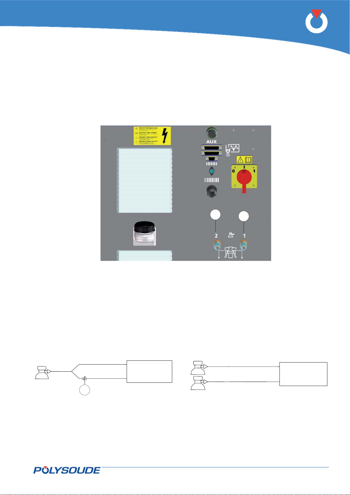
Fig.4.5, Fig.4.6 & Fig.4.7 - Rep.1 Gas 1
Fig.4.5, Fig.4.6 & Fig.4.7 - Rep.2 Gas 2
To ensure a successful welding cycle, please provide for a minimum of 2.5 L/min for Argon gas fl ow and 8 L/
min for Helium fl ow.
Continuous gas fl ow option for P6 with UHP welding head
A gas fl ow continuing outside the weld cycle can be obtained, if a UHP welding head is connected to a power
source which is equipped with the continuous gas fl ow option.
The fl owrate of this gas is controlled by:
a manual adjustment valve inserted into the circuit if the gas used (refer to Fig.4.6) is the same as the •
welding gas. The valve (Fig.4.6 - item A) is adjusted manually.
the litre fl owmeter installed in the gas source (cylinder or manifold) if the gas used (refer to Fig.4.7) is not •
the same as the welding gas. Connection is made at the rear of the generator at gas inlet 2).
Connection is made at the rear of the power source at gas inlet 2.
How it works
Depending on the power source confi guration, the gas fl ows as soon as the power source is switched on with a
rate set by the manual adjustment valve or the litre fl owmeter installed at the gas source.
When the welding cycle is started, with or without arc, the gas fl ow is switched to the welding gas with the rate
set by the litre fl owmeter on the welding gas source and ends when the post-welding gas timer has elapsed.
Afterwards the gas keeps on fl owing at the continuous gas fl ow rate.
As long as a UHP head is connected to the power source, the internal cooling circuit is inhibited.
Once the head is disconnected, the continuous gas fl ow is stopped.
24-92 PN-0509076 Rev. 16
THE ART OF WELDING
Page 25
P6
1
2
Fig. 4.5 - Connection of the gas supply to the power source P6
2
P6
1
1
2
P6
A
Fig. 4.6 - Connection diagram if one gas is used
PN-0509076 Rev. 16 25-92
THE ART OF WELDING
Fig. 4.7 - Connection diagram if two different gases
are used
Page 26
P6
Connecting the acquisition module4. 3.
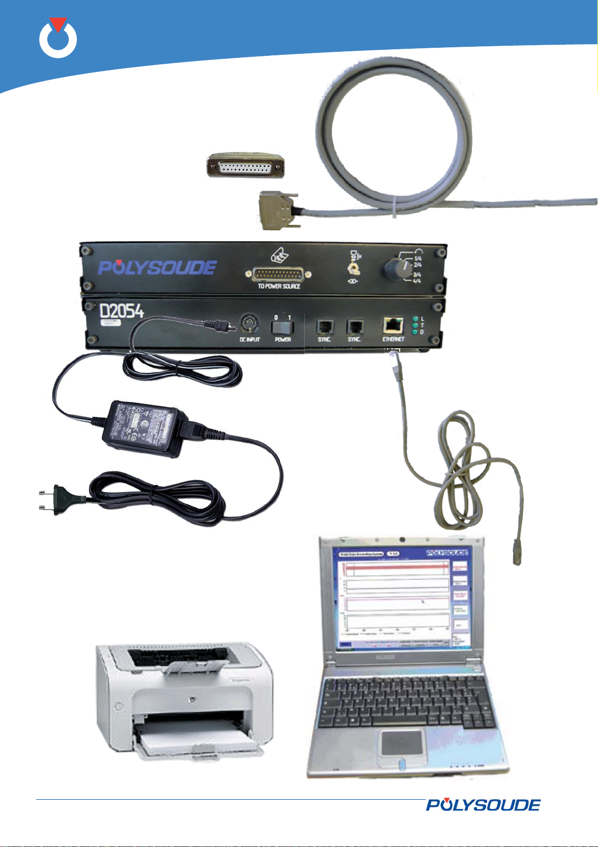
240 V
Acquisition module
Ethernet cable RJ45
AC
Power supply
Printer (optional)
26-92 PN-0509076 Rev. 16
Notebook P.C.
THE ART OF WELDING
Page 27
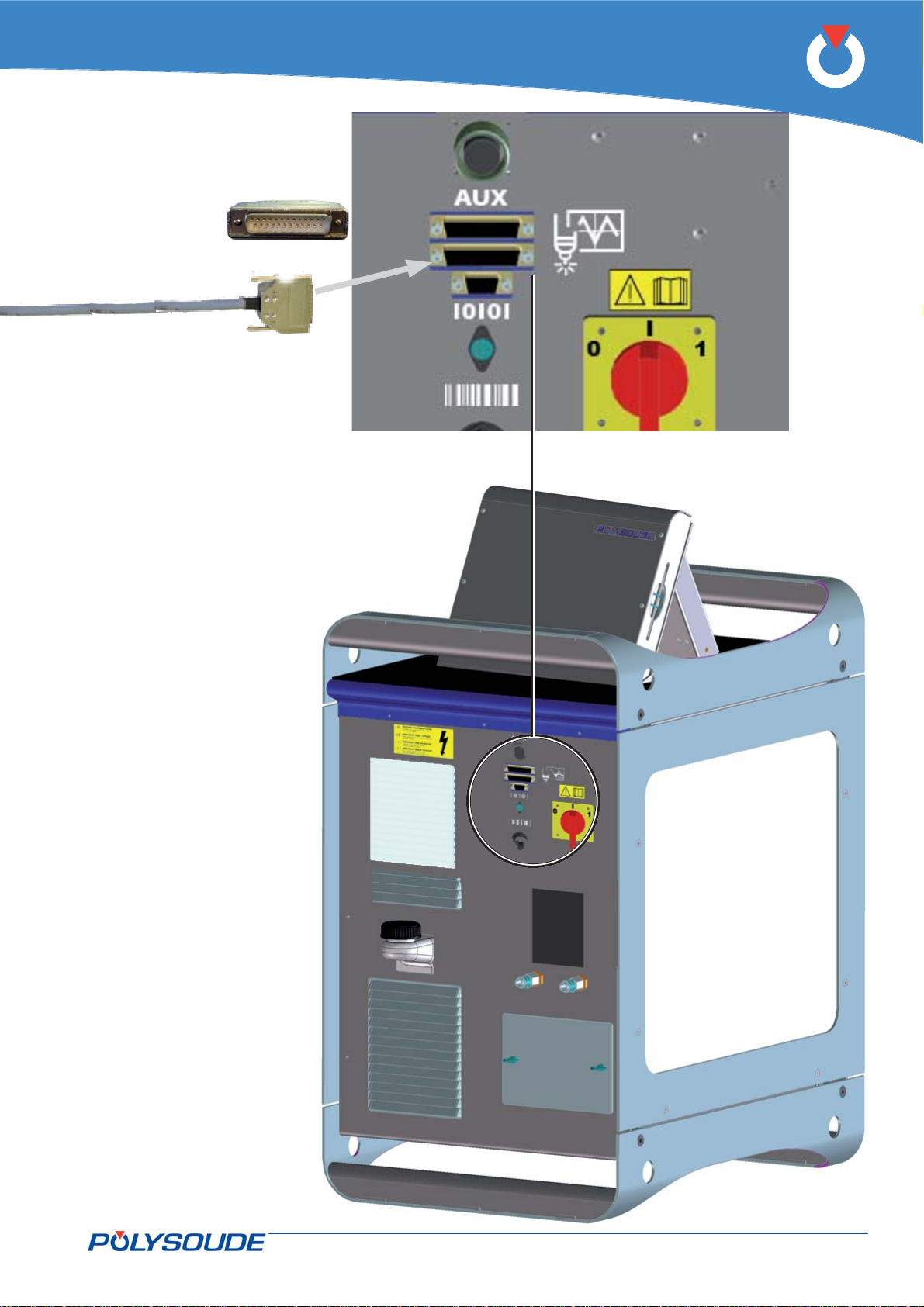
Measure connector of power source
P6
P6 welding power source
PN-0509076 Rev. 16 27-92
THE ART OF WELDING
Page 28

P6
PC/Power source connection4. 3. 1.
If a PC is used you must use the RJ45 cable supplied with
the power source. Failure to use this cable may result in
hazards for the user. Polysoude declines to accept any liability unless the PC/Power source connection is made with
the RJ45 cable.
Connect the PC to the RJ45 connector situated at the front of the power source with the Ethernet cable
supplied.
The default IP address of the power source is
172.16.200.20
Confi guring the power source’s IP address :
Press the button BT 6 “I-” of the remote control pendant during several seconds.
On the display of the remote control pendant appears:
>IPAdress
Tacho
Select “IP Adress” with the button BT 1.
Confi rm the selection with the button BT 3 “N+”.
On the display of the remote control pendant appears Ip number
The IP address is in the form of four numeric blocks that can be modifi ed by BT2 and BT3. Moving from one
block to another is effected by a pulse on BT1.
Once you have reached the last block, pressing once more on BT1 stores the new entry in memory and terminates the IP address modifi cation procedure.
Confi guring the IP address in Windows™ 2000, XP or NT :
In order to modify the IP address of the PC.
In the Start menu, select Settings > Network Connections.
The list of connections appears. Right click on the connection whose address is to be changed. Then click on
Properties. The «General» tab contains all of the elements used for the connection. Click on the Networking
tab.
Double click on Internet protocol (TCP/IP), and tick the option «Use the following IP address» and enter the
address of the power source.
28-92 PN-0509076 Rev. 16
THE ART OF WELDING
Page 29
P6
Equipment compatibility4. 3. 2.
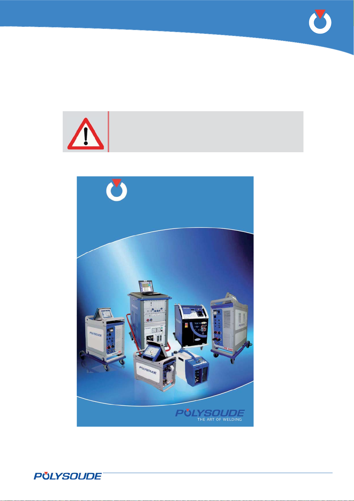
To know the standard axis confi guration to equipments Polysoude, see the memo ‚‚Axis Confi guration
Standard“.
L’opérateur doit impérativement respecter le choix de types
d’axes spécifi és par Polysoude.
En cas de non respect de ce choix il existe de forts risques de
destruction du matériel.
Configurations des
Configurations des
axes standard
axes standard
(têtes et générateurs)
(têtes et générateurs)
Mémo PN-0212017
Mémo PN-0212017
EDITION 2012-01
EDITION 2012-01
Fig.4.8 - Memo Axis confi guration standard
PN-0509076 Rev. 16 29-92
THE ART OF WELDING
THE ART OF WELDING
THE ART OF WELDING
Page 30
P6
Setting to work4. 4.
Remotes control on board4. 4. 1.
When using the remote control board on TS, MW and hand torches,
must keep pressing the button for one second that action be taken into
account
Connection of the remote control unit 4. 4. 2.
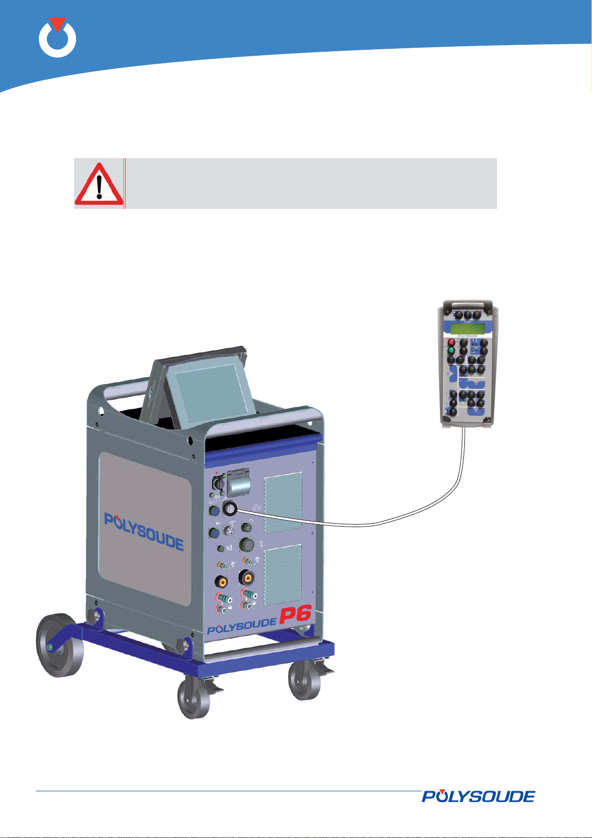
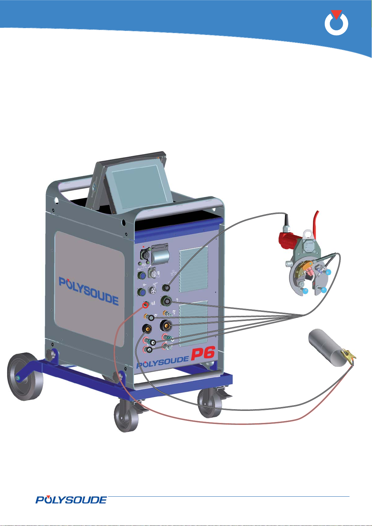
The cable of the remote control unit is connected by means of a bayonet fi tting on the connector panel.
Power sources equipped with the emergency stop option cannot be powered up if the remote control unit is not
connected.
Fig. 4.9 - Connection of the remote control unit to the P6 power source
30-92 PN-0509076 Rev. 16
THE ART OF WELDING
Page 31
P6
Connection of a gas cooled closed chamber welding head4. 4. 3.
Polysoude UHP heads belong to this group.
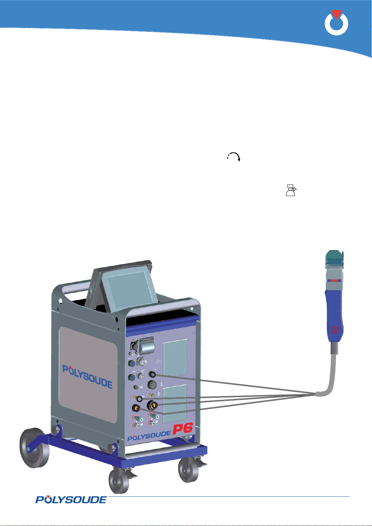
Connection of the electrode current cable
Connect the current cable with the quick connector to the “-” terminal on the connector panel, locking it by
rotation to the right. This terminal is not marked by a colour.
Connection of the earth cable
Connect the earth cable to the “+” terminal on the connector panel. The terminal is surrounded by a red ring.
The connection is made with a quick connector, locked by rotation to the right. The cable end is marked red.
Connection of the rotation motor cable
Connection is made on the connector panel at connector (symbol
properly tightened, otherwise the system may not function correctly.
Connection of the torch shielding gas
The connection is made with a quick push-pull coupling on the connector panel (symbol
Connection of a shunt to the cooling fault detection circuit
On power sources before v.2.5.0 version, it is necessary to shunt the cooling circuit to prevent a coolant fault
detection.
). Make sure that the securing ring is
).
Fig. 4.11 - Connection of a gas cooled closed cham-
ber welding head
PN-0509076 Rev. 16 31-92
THE ART OF WELDING
Page 32

P6
Connection of an open welding head of the MU type or a tube/tubesheet welding head of the type 4. 4. 4.
TS or TP
Connection of the electrode current cable
Connect the current cable with the quick connector to the “-” terminal on the connector panel, locking it by
rotation to the right.
Connection of the earth cable
Connect the earth cable to the “+” terminal on the connector panel. The terminal is surrounded by a red ring.
The connection is made with a quick connector, locked by rotation to the right. Connect the other end of the
cable to the workpiece, as close as possible to the joint to be welded, in an area free from grease and oxide.
Connection of the AVC measurement plug to the workpiece
If servo control of height to the arc voltage is required, this voltage must be measured on the workpiece directly and as close as possible to the electrode. A white wire, tied to the earth cable makes it possible to
measure the arc voltage on the workpiece. At the power source end, this wire is connected to the front con-
U+
nector panel FA 26 (symbol
) with a screw connector.
Connection of the rotation motor cable
Connection is made on the connector panel at connector (symbol
properly tightened, otherwise the system may not function correctly.
Connection of the AVC/oscillation motor cable
Connect the cable to socket (symbol ) on the front connection panel.
Connection of the torch shielding gas
The connection is made with a quick push-pull coupling on the connector panel (symbol
Connection of the cooling circuit
The connection is made with 2 quick couplings on the front connector panel (symbols
). Make sure that the securing ring is
).
and ).
32-92 PN-0509076 Rev. 16
THE ART OF WELDING
Page 33
P6
Fig. 4.10 - Connection of an open welding head of the MU type or a tube/tubesheet welding head of the type
TS or TP
PN-0509076 Rev. 16 33-92
THE ART OF WELDING
Page 34
P6
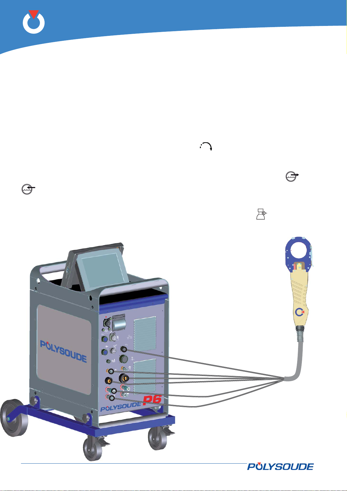
Connection of a liquid cooled closed chamber welding head4. 4. 5.
Gas cooled closed chamber welding heads of the type K and MW old versions belong to this group.
Connection of the electrode current cable
Connect the current cable with the quick connector to the "-" terminal, locking it by a short rotation to the right.
This terminal is not marked by a colour.
Connection of the earth cable
Connect the earth cable to the “+” terminal on the connector panel. The terminal is surrounded by a red ring.
The connection is made with a quick connector, locked by rotation to the right. The cable end is marked red.
Connection of the rotation motor cable
Connection is made on the connector panel at connector (symbol
properly tightened, otherwise the system may not function correctly.
Connection of the cooling circuit
The connection is made with 2 quick couplings on the front connector panel (symbols
).
Connection of the torch shielding gas
The connection is made with a quick push-pull coupling on the connector panel (symbol
). Make sure that the securing ring is
).
and
Fig. 4.12 - Connection of a liquid cooled closed
chamber welding head
34-92 PN-0509076 Rev. 16
THE ART OF WELDING
Page 35
P6
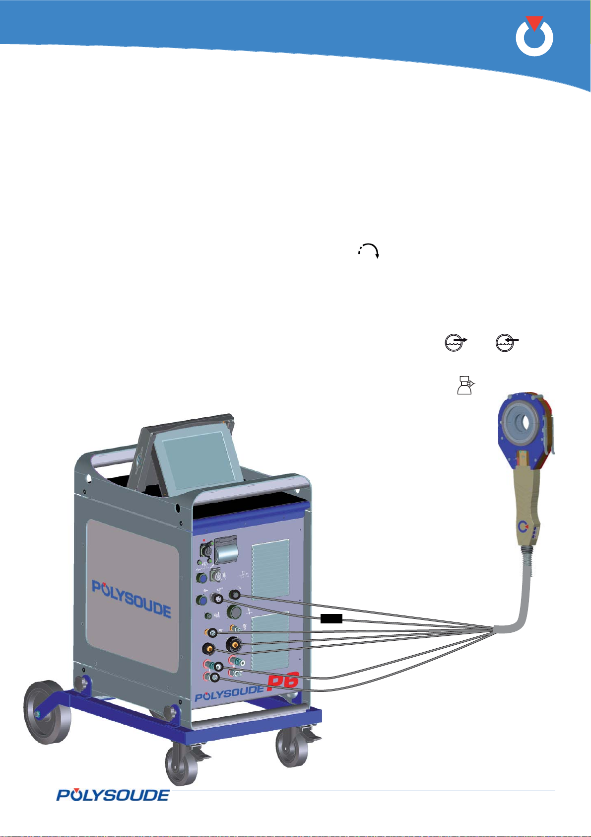
Connection of a liquid cooled closed chamber welding head with integrated command buttons (MW 4. 4. 6.
40-3, 65-3, 115-3, 170)
Connection of the electrode current cable
Connect the current cable with the quick connector to the "-" terminal, locking it by a short rotation to the right.
This terminal is not marked by a colour.
Connection of the earth cable
Connect the earth cable to the “+” terminal on the connector panel. The terminal is surrounded by a red ring.
The connection is made with a quick connector, locked by rotation to the right. The cable end is marked red.
Connection of the rotation motor cable
Connection is made at the front of the P6 at connector (symbol
properly tightened, otherwise the system may not function correctly.
Connection of the manual command cable of the type MW heads
Join the manual command cable to the connector FA 5 on the connection panel of the power source with
connection ref 0023000901..
Connection of the cooling circuit
The connection is made with 2 quick couplings on the front connector panel (symbols
Connection of the torch shielding gas
The connection is made with a quick push-pull coupling on the connector panel (symbol
Connection of the integrated commands
A connection kit is arranged on the supply from head to power source.
). Make sure that the securing ring is
and ).
).
Fig. 4.13 - Connection of a liquid cooled closed
chamber welding head with integrated
command buttons
PN-0509076 Rev. 16 35-92
THE ART OF WELDING
Page 36
P6
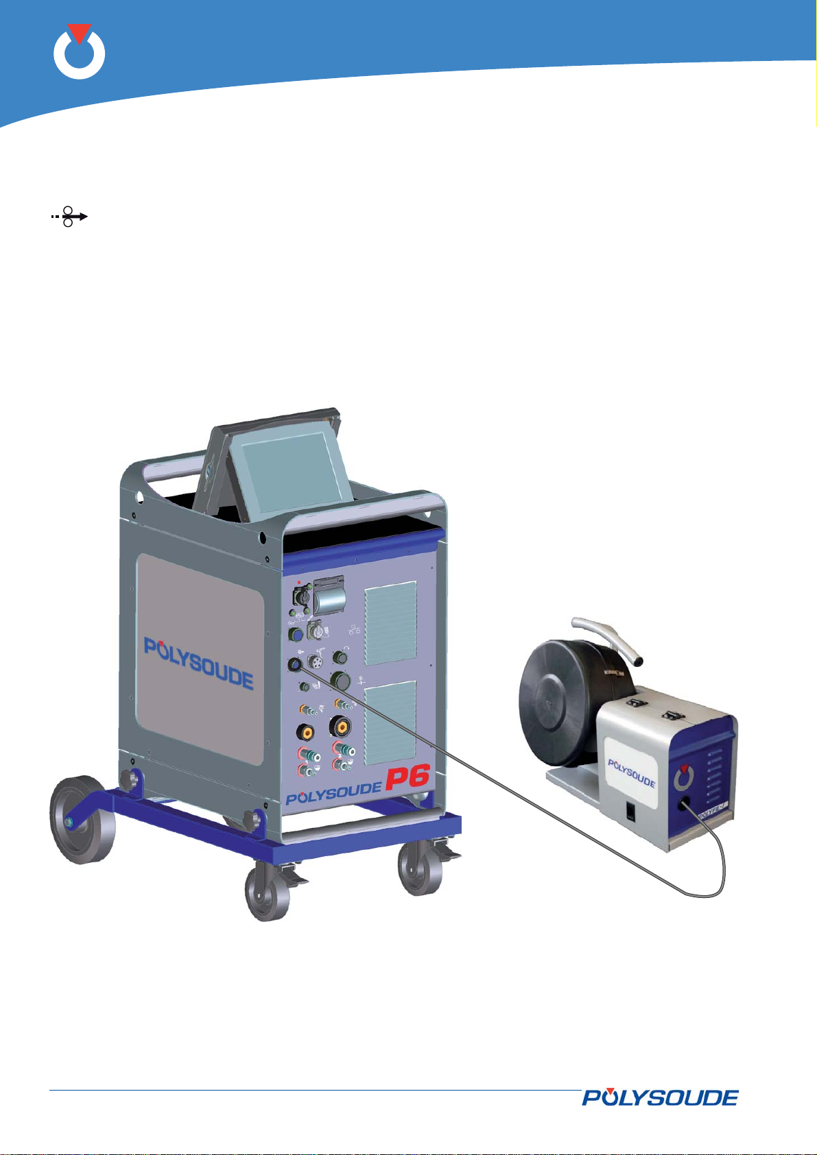
Connection of a wire feed unit4. 4. 7.
The wire feed unit is connected at the front connection panel of the P6 by a screw connector (symbol
). Make sure that the securing ring is properly tightened, otherwise the system may not function correct-
ly.
Fig. 4.14 - Connection of a wire feed unit
36-92 PN-0509076 Rev. 16
THE ART OF WELDING
Page 37
P6
Connection of a closed chamber welding head equipped with tacheometry (option)4. 4. 8.
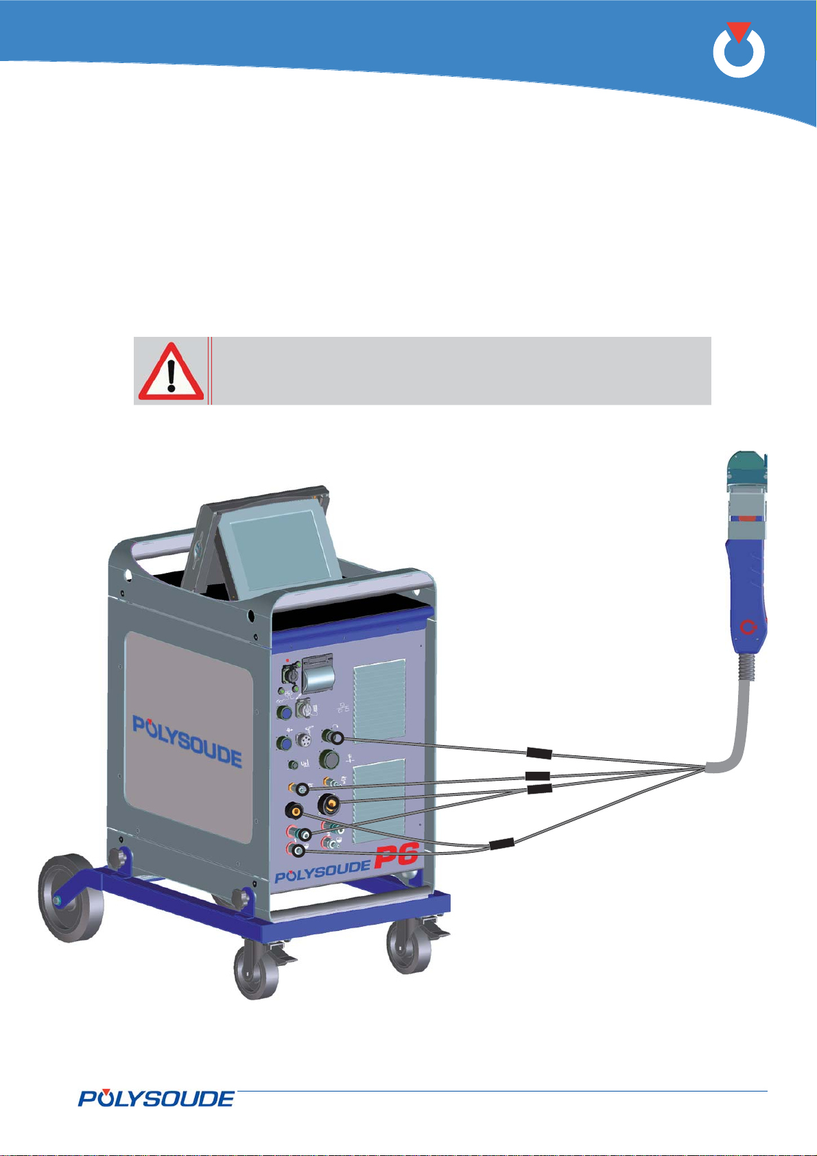
Adapters are mounted in the lines from the welding head to the power source/cooling system assembly:
Welding gas.•
Torch rotation.•
Electrode current and water return.•
Earth current and water feed.•
The connection of these adapters to the power source and cooling circuit is identical to those of a liquid cooled
closed chamber welding head.
To avoid damage or poor weld quality it is recommended to readjust the
tachometer of the welding head while putting into operation the equipment.
See as well section “Adjustment of the tachometer” in chapter “Maintenance” of the present paper.
Fig. 4.15 - Connection of a closed chamber welding head equipped with tacheometry
PN-0509076 Rev. 16 37-92
THE ART OF WELDING
Page 38
P6
Connection of a manual torch with double command4. 4. 9.
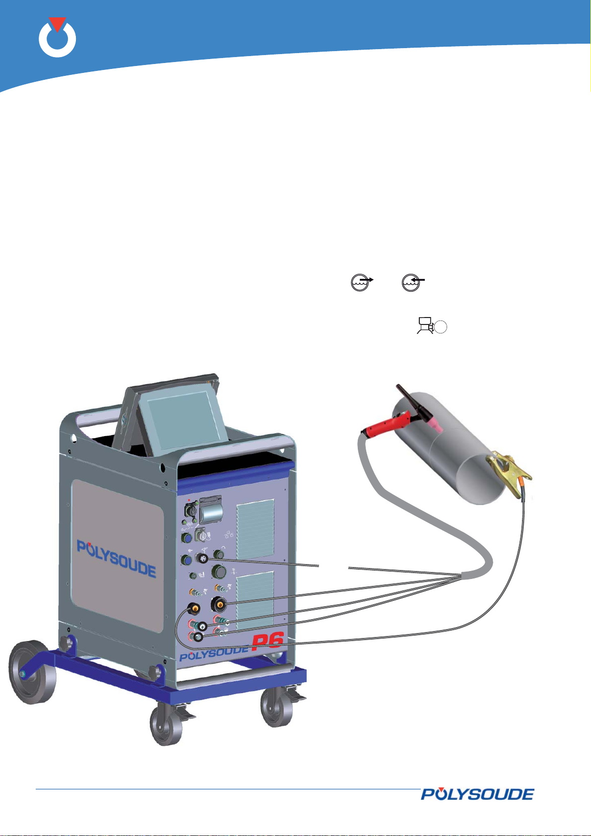
Connection of the electrode current cable
Connect the current cable on the “-” terminal with the quick connector, locking it by rotation to the right.
Connection of the earth cable
Connect the earth cable to the “+” terminal surrounded by a red ring. Connection is made with a quick connector, with right hand locking. Connect the other end of the cable to the workpiece, as close as possible to the joint
to be welded, in an area free from grease and oxide.
Connection of the command cable
The command cable of the manual torch has to be joined to the socket FA 5 on the connector panel. Use the
adapter for manual torch 0023000901.
Connection of the cooling circuit (option)
Connection is made by 2 quick couplings on the front panel (symbols
Connection of the torch shielding gas
Connection is made with a quick push-pull coupling on the connector panel (symbol
FA 5
and ).
1
).
Fig. 4.16 - Connection of a manual torch
38-92 PN-0509076 Rev. 16
THE ART OF WELDING
Page 39

P6
Detection of the welding head4. 4. 10.
If the head connected to the power source does not correspond with the welding procedure selected, the cycle
will not start.
Select the correct WP or change the head appropriately to enable the welding cycle to start.
Detection of the «closed head» position4. 4. 11.
If an old type of head is used (MW, MU III, ...), the power source starts to strike an arc provided that the head
is in the «open head» position. If this is not so it will not start the cycle.
If there is any douBT make a test. No damage will occur.
With the various detection functions not operating, the operator has to pay more attention.
PN-0509076 Rev. 16 39-92
THE ART OF WELDING
Page 40
P6
Oxygen meter option4. 4. 12.
This chapter provides a description of the interface between the power source and the oxygen meter.
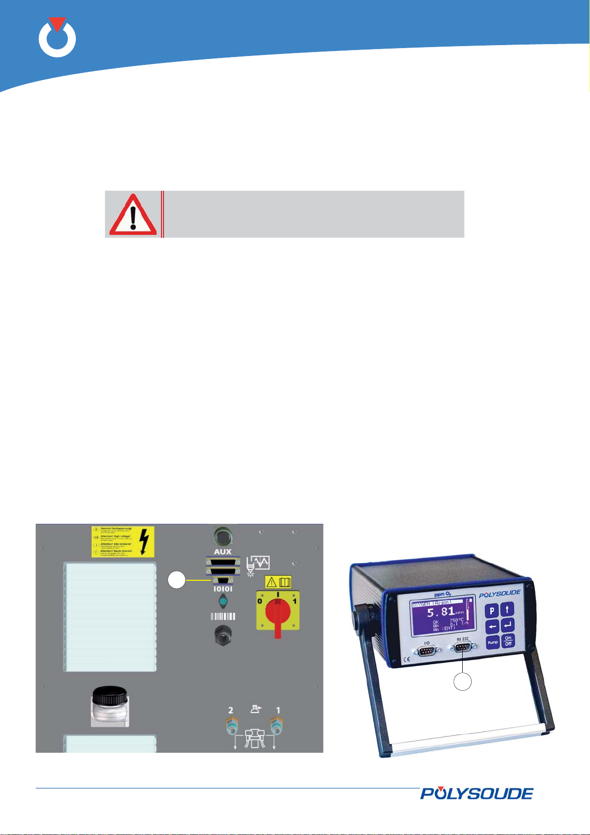
It is possible to install an oxygen meter to the power source-HMI assembly. Communication
for the oxygen meter and the power source is provided by an RS232 serial port cable whose operation is fi xed
at 19200 baud.
In order to use an oxygen meter with the power source it
is essential to use the RS232 serial port cable supplied by
Polysoude. Use of any other cable will result in major malfunction.
Connect the RS232 serial port cable to connector FA 22 (Fig.4.16 – Pos. 1) on the connection panel at the rear
of the power source. Connect the other end of the RS232 serial port cable to the front panel of the oxygen meter
(Fig.4.17 – Pos. 1).
Please refer to the HMI user manual in order to adjust settings of the oxygen meter on the HMI.
It is particularly important to refer to the oxygen meter user manual. In it, you will fi nd detailed explanations of
the various functions of the equipment.
Oxygen meter settings
Two parameters must be set on the oxygen meter and two parameters must be checked before use.
If one of these parameters is not set correctly or if the value received by the HMI differs from the value programmed, the HMI will indicate “Oxygen fault”.
The parameters to be checked before use are:
The temperature of the probe must be at 750°C (permitted value between 748 and 752°C).•
The airfl ow must be adjusted to between 5L/min and 10L/min. The pump must be running. If it is not, the •
HMI will indicate “Oxygen fault”.
The parameters to be set before use are:
The «Documentation» line of the display must be at «Off» in the «Basic Settings» menu.•
The value of «Baud» must be set to 19200 in the «System Settings» menu.•
In order to perform these settings and to start to use the equipment, please refer to the oxygen meter user
manual.
1
2
Fig. 4.17 - Power source rear connection panel and oxygen meter
40-92 PN-0509076 Rev. 16
THE ART OF WELDING
Page 41
P6
Option commands mechanised equipment4. 4. 13.
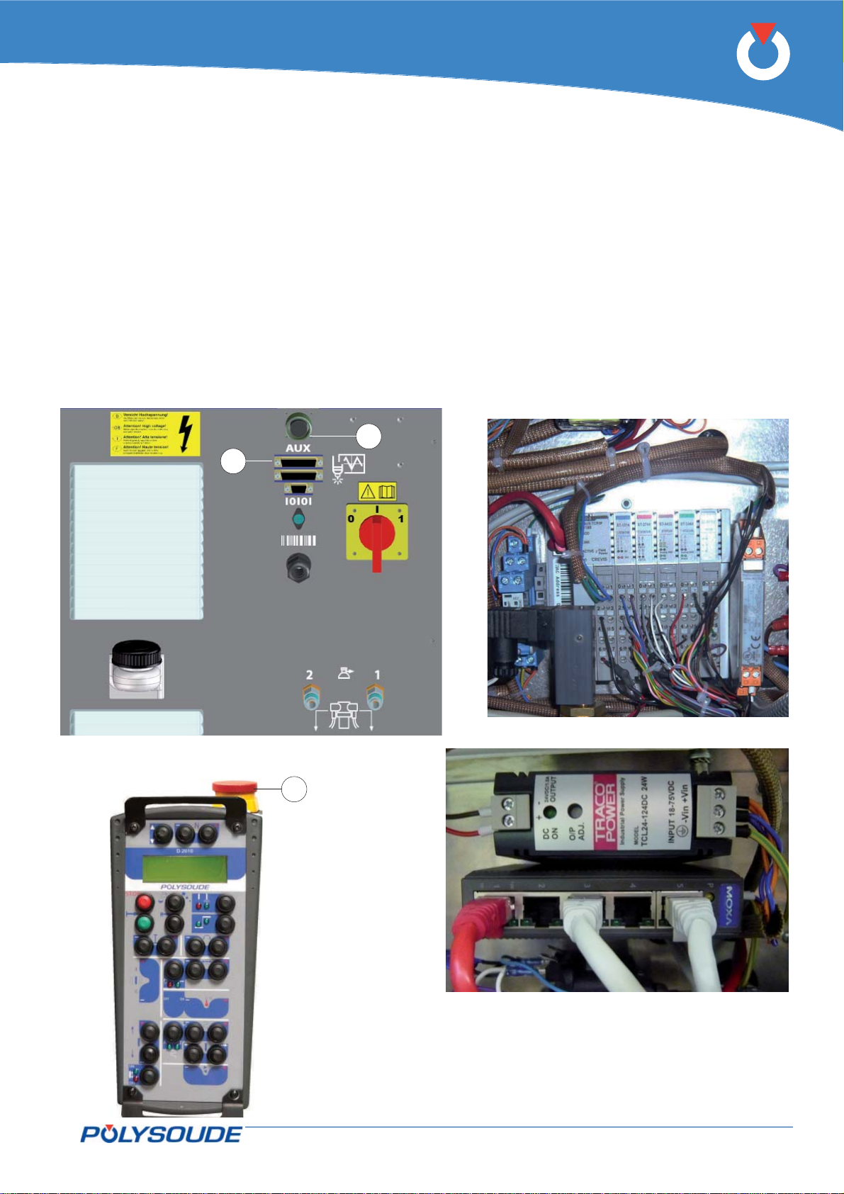
With this option the power source operates mechanised equipment type boom, positioner etc. The
power source is equipped with modules (Fig.4.19) of
an Ethernet switch and power supply (Fig. 4.20), and
is associated with an external drive.
To access the modules must remove the left side plate
of the power source. To access the Ethernet switch
and power supply must be fi led right side plate of the
power source.
The drive connects to the power source via a cable
equipped with an auxiliary connector 44–pin (0-10 V
or -10/+10 V signal, right stop and left stop, drive
connect OK, direction control, triggering the start
and stop welding cycle).
2
1
The auxiliary connector is connected to the outlet
FA 20 (Fig.4.18 - Pos. 1) on the back cover of the
power source.
The power source is equipped with an emergency
stop (Fig.4.18 - Pos. 2) that is used to connect an
emergency stop button on a bay, a desk or other
customer equipment. The remote control is also
equipped with emergency stop button (Fig.4.21 Pos. 1).
These emergency stops power cut stops of the entire
installation.
Fig. 4.19 - Modules
Fig. 4.18 - Power source rear connection panel
1
Fig. 4.20 - Ethernet swtich and power supply
Fig. 4.21 - Remote control unit
with emergency stop
PN-0509076 Rev. 16 41-92
THE ART OF WELDING
Page 42
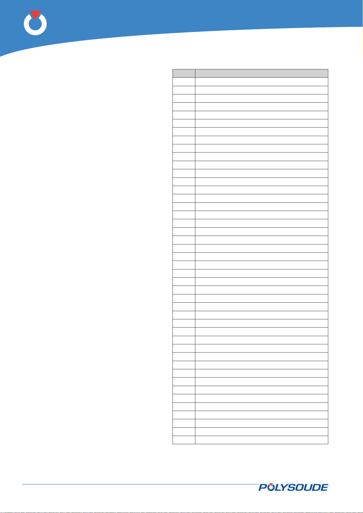
P6
The rear connector 44–pin connector allows the
drive. Here the representation of the connector
with the I / O available.
Item Description
1 Way A encoder
2 0V encoder
30V
4 Drive connects ready
5 Order cycle stop
6 24 V max (input)
7 Reverse gear
8 24 V max (input)
9 0V motor
10 Not used (0->10V signal)
11 Not used
12 Not used
13
14
15
16 Way B encoder
17 0V encoder
18 24V output
19 Left stop
20 Order start cycle
21 Forward run
22 24 V max (input)
23 State with arc
24
25 Not used (0->10V input)
26
27
28
29
30
31 Not used
32 Not used
33 Right stop
34 Downslope cycle control
35 24 V max (input)
36 State cycle
37 Set motor 0->10V or -10V->10V
38
39
40
41
42
43
44
Fig. 4.22 - Connector wiring
42-92 PN-0509076 Rev. 16
THE ART OF WELDING
Page 43

P6
PN-0509076 Rev. 16 43-92
THE ART OF WELDING
Page 44
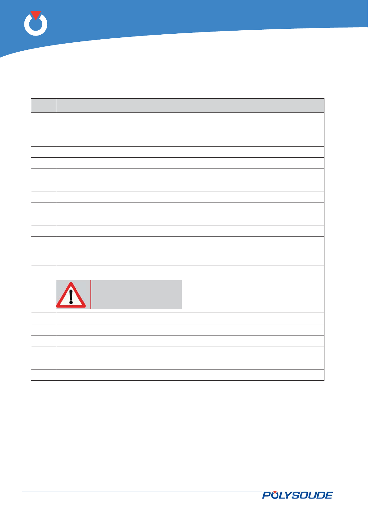
P6
Description of controls4. 5.
Front control and connection panel4. 5. 1.
Item Designation
FA 2 Connection of the remote control unit.
FA 3 Connection of the rotation cable.
FA 4 Connection of the wire feeder.
FA 5 Connection of the command cable of a manual torch or of a type MW welding head.
FA 7 Connection of a second gas (option).
FA 9 Connection of the torch gas.
FA 10 Connection of the earth cable.
FA 11 Connection of the torch current cable.
FA 12 Coolant outlet connection 1.
FA 13 Coolant return connection 1.
FA 14 Connection of the PC interface (RJ45).
FA 15 Connection of the USB key.
FA 16
FA 17
FA 18 Write command on the USB key.
FA 19 Read command on the USB key.
FA 24 Coolant outlet connection 2.
FA 25 Coolant return connection 2.
FA 26 Connection of workpiece U
FA 27 Connection of AVC and oscillation cable
Short press: a ticket is printed summarising the welding carried out.
Long press (> 2 s): print-out of the program selected.
Indicator light; on when USB key busy with reading/writing.
Do not remove the USB key
when the light is illuminated.
cable
arc
44-92 PN-0509076 Rev. 16
THE ART OF WELDING
Page 45

FA 17
FA 15
FA 19
P6
FA 16
FA 18
FA 2
FA 5
FA 4
FA 26
FA 9
FA 10
FA 12
FA 13
FA 14
FA 3
FA 27
FA 7
FA 11
FA 24
FA 25
Fig. 4.23 - Front connector panel
PN-0509076 Rev. 16 45-92
THE ART OF WELDING
Page 46
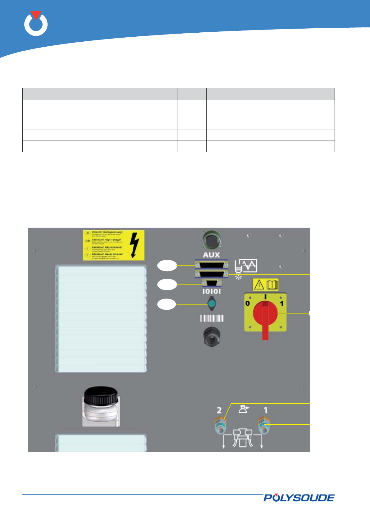
P6
Rear connector panel4. 5. 2.
Item Designation Item Designation
FA 1 On/off switch. FA 21 Connection of the data acquisition unit..
FA 6 Connection of the second gas supply
FA 22 Serial connection RS232..
(option).
FA 8 Connection of the shielding gas supply. FA 23 Connection of a bar code reader.
FA 20 Connection of auxiliary equipment.
FA 20
FA 22
FA 21
Fig. 4.24 - Rear connector panel
FA 23
FA 1
FA 8
FA 6
46-92 PN-0509076 Rev. 16
THE ART OF WELDING
Page 47
P6
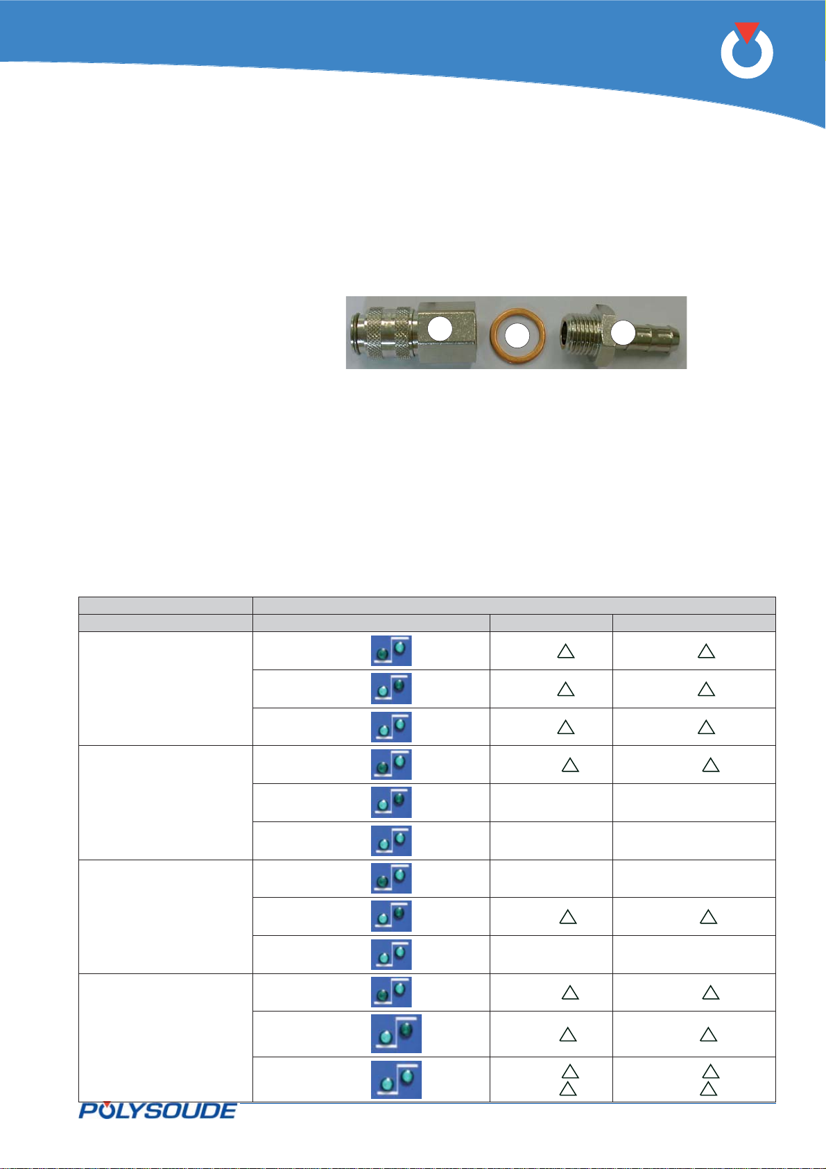
Quick connector gas input4. 5. 3.
Gas fi tting female - Part number 01514008 - Item 1.•
Ribbing bush - Part number 00692055 - Item 2.•
Copper seal 13.5x18x1.5. -No part number - Item 3.•
1
Fig. 4.25 - Quick connector gas input
3
2
Remote control units 6 axis 00261691014. 5. 4.
Using the remote control to regulate the AVC4. 5. 4. 1.
Remote control
Programmed regulation Override mode AVC + AVC -
Smooth voltage
High
Low
High and low
U + U -
U + U -
U + U -
High
High voltage
Low voltage
High and low voltage
PN-0509076 Rev. 16 47-92
THE ART OF WELDING
Low --
High and low
High
Low
High and low --
High
Low
High and low
Uh + Uh -
--
--
Ul + Ul -
Uh + Uh -
Ul + Ul -
Uh +
Ul +
Uh -
Ul -
Page 48
P6
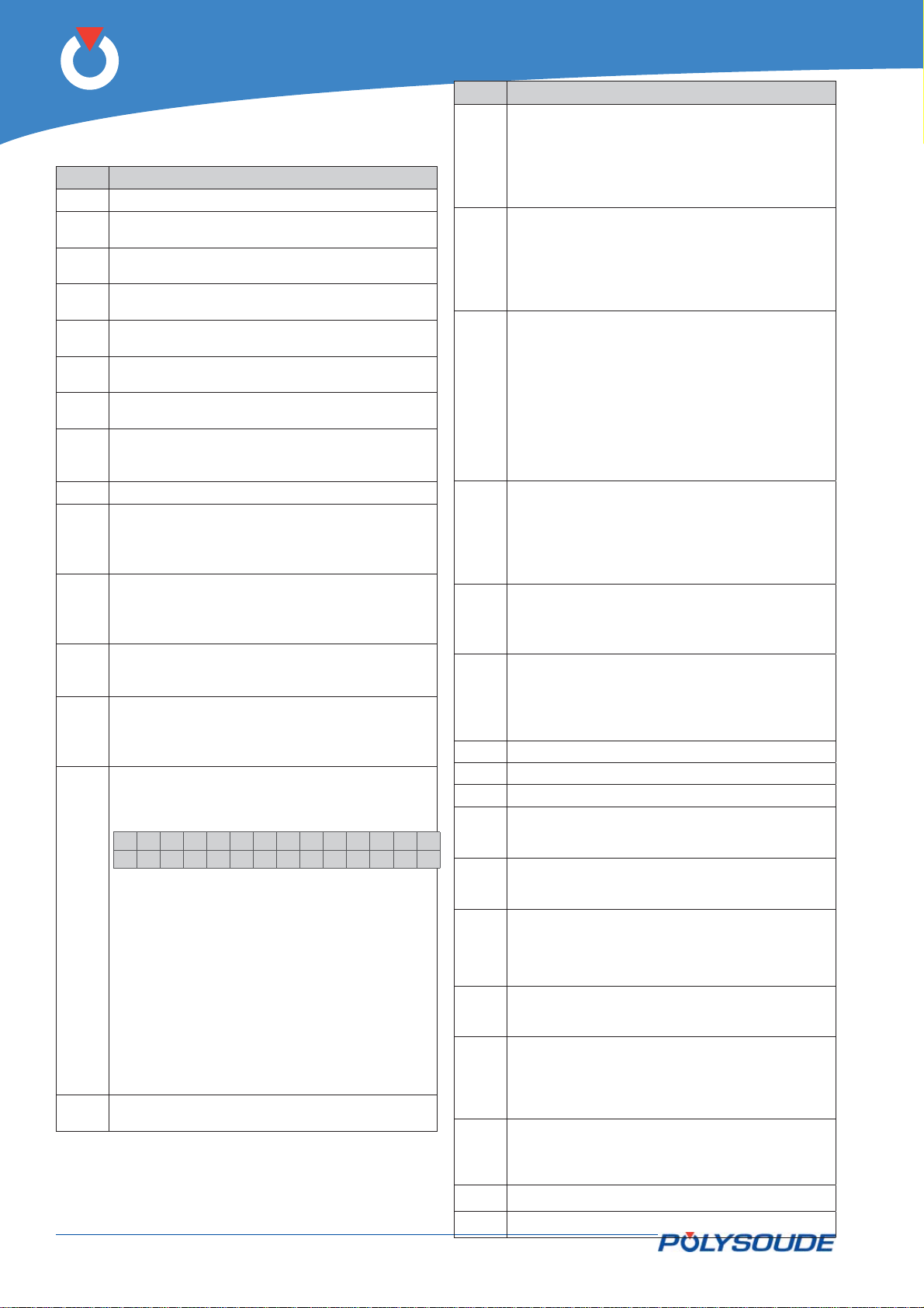
Item Designation
BT 8 Push button operating in two modes:
Functions of elements of remote control unit4. 5. 4. 2.
Item Designation
AF 1 2 line 16 character backlight display.
V 1 Red indicator illuminated: Simulation without
BT 9 Push button operating in two modes:
arc.
V 2 Green indicator illuminated: Weld mode with
arc.
V 3 Green indicator illuminated: Increment ac-
tions on low level.
V 4 Green indicator illuminated: Increment ac-
BT 10 Push button operating in two modes:
tions on high level.
V 3+
Green and red indicator illuminated: Incre-
V 4
ment actions on low and high level.
V 5 Red indicator illuminated: fi ller wire operation
during weld cycle controlled by BT 10.
V 6 Green indicator illuminated: automatic fi ller
wire operation according to programmed
parameters.
BT 1 Push button for line toggling on the display.
BT 11 Push button operating in two modes:
BT 2 Push button to move down in the WP or
program list or to decrease a numeric value.
After 1 s of continued pushing, the automatic
mode is applied.
BT 3 Push button to move up in the WP or pro-
gram list or to increase a numeric value.
BT 12 Push button to toggle between the automatic
After 1 s of continued pushing, the automatic
mode is applied.
BT 4 Out of cycle: push button to toggle between
simulation without arc and weld mode with
BT 13 Push button operating in two modes:
arc (associated with V 1 & V 2).
BT 5 Push button to toggle between increment ac-
tions on low level, increment actions on high
level or increment actions on both levels (associated with V 3 & V 4).
BT 6 Out cycle : Press the button BT 6 “I-” of
the remote control pendant during several
seconds. On the display of the remote control
pendant appears:
>IPAdress
Tacho
BT 14 Push button «Start cycle with restart».
BT 15 Push button "Start cycle".
BT 16 Push button "Stop cycle immediately".
BT 18 Push button operating in two modes:
BT 19 Push button operating in two modes:
Select “IP Adress” with the button BT 1.
Confi rm the selection with the button BT 3
“N+”.
Modifi cation of the IP address. The IP address
is in the form of four numeric blocks that can be
modifi ed by BT 2 and BT 3. Moving from one
block to another is effected by a pulse on BT 1.
Once you have reached the last block, pressing once more on BT 1 stores the new entry in
memory and terminates the IP address modifi -
cation procedure
During a weld cycle: Decrementation of the weld
current level selected with BT 5.
BT 20
BT 21
BT 22
BT 7 For a weld cycle: Incrementation of the
weld current level selected with BT 5.
BT 23
BT 24
BT 25
48-92 PN-0509076 Rev. 16
Out of cycle: Manual rotation rearwards at
low speed for 1 s, at medium speed for 2 s,
afterwards at full speed.
For a weld cycle: Decrementation of the
rotation speed level selected with BT 5.
Out of cycle: Manual rotation forwards at
low speed for 1 s, at medium speed for 2 s,
afterwards at full speed.
For a weld cycle: Incrementation of the
rotation speed level selected with BT 5.
Out of cycle in automatic mode (V 6 illuminated): Manual wire feeding forwards at
low speed for 1 s, at medium speed for 2 s,
afterwards at full speed.
Out of cycle in manual mode (V 5 illuminated): The fi rst press starts wire feeding at
high speed, the second press stops it.
For a weld cycle: Incrementation of the
wire feeding speed level selected with BT 5.
Out of cycle: Manual wire feeding rearwards
at low speed for 1 s, at medium speed for 2
s, afterwards at full speed.
For a weld cycle: Decrement the wire feeding speed level selected with BT 5.
wire feeding mode (indicator V 6 illuminated)
or the manual wire feeding mode (indicator
V 5 illuminated).
Out of cycle: coolant pump, gas 1 and gas 2
commands.
For a weld cycle: Manual cycle stop with
downslope.
Out of cycle: Raise torch.
For a weld cycle : Increment torch height.
Out of cycle : Lower torch.
For a weld cycle : decrement torch height.
Push button to choose function in loop.
Suspension of the AVC (V 10 illuminated). Running of the AVC (V 9 illuminated). -
Function not available
Push button to choose delta corrections.
In amplitude "A" ( - V 7 illuminated).
In time "T" ( - V 8 illuminated).
Push button operating in two modes:
Out of cycle: torch oscillation with self-centering.
For a weld cycle: Decrease of the oscillation in
amplitude or in time according to BT 21 position.
Push button operating in two modes:
Out of cycle: no action.
For a weld cycle: Increase of the oscillation in
amplitude or in time according to BT 21 position.
Push button to off-set torch to the left.
Push button to off-set torch to the right.
THE ART OF WELDING
Page 49
BT 2
P6
BT 1
AF 1
BT 13
BT 16
BT 15
BT 14
BT 6
BT 7
BT 12
BT 21
BT 18
V 7
BT 19
BT 3
V 1
V 2
BT 4
V 3
BT 5
V 4
BT 8
BT 9
BT 10
BT 11
V 5
V 6
BT 22
BT 23
BT 25
V 9
V 10
BT 20
BT 24
V 8
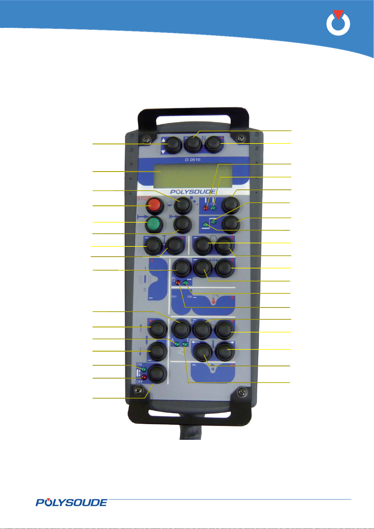
Fig. 4.26 - Remote control unit 6 axis
PN-0509076 Rev. 16 49-92
THE ART OF WELDING
Page 50
P6
Remote control pendant 4 axis 00261491014. 5. 5.
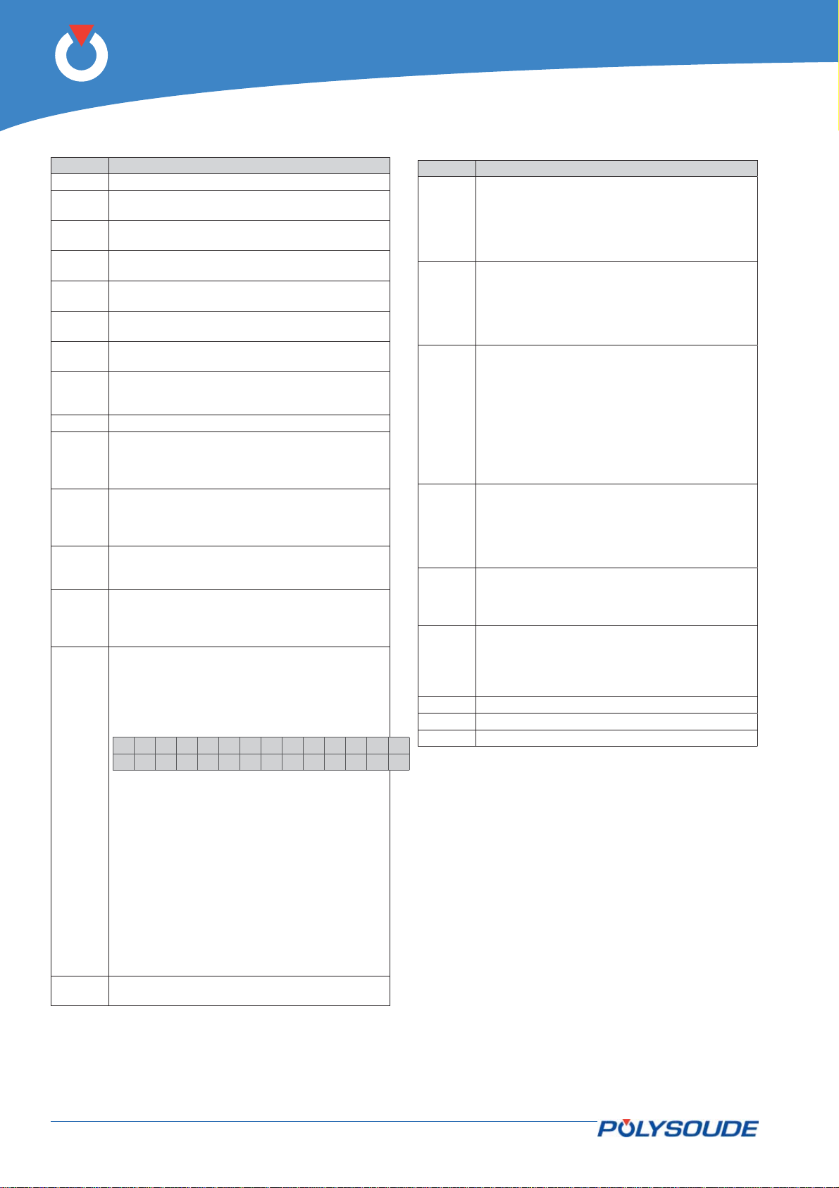
Function of operating elements
Pos Designation
AF 1 2 line 16 character backlight display.
V 1 Red indicator illuminated: Simulation without
V 2 Green indicator illuminated: Weld mode with
V 3 Green indicator illuminated: Increment actions
V 4 Green indicator illuminated: Increment actions
V 3+
V 4
V 5 Red indicator illuminated: fi ller wire operation
V 6 Green indicator illuminated: automatic fi ller
BT 1 Push button for line toggling on the display.
BT 2 Push button to move down in the WP or pro-
BT 3 Push button to move up in the WP or program
BT 4 Push button to toggle between simulation
BT 5 Push button to toggle between increment ac-
BT 6
arc.
arc.
on low level.
on high level.
Green and red indicator illuminated: Increment
actions on low and high level.
during weld cycle controlled by BT 10.
wire operation according to programmed parameters.
gram list or to decrease a numeric value. After
1 s of continued pushing, the automatic mode
is applied.
list or to increase a numeric value. After 1 s
of continued pushing, the automatic mode is
applied.
without arc and weld mode with arc (associated
with V 1 & V 2).
tions on low level, increment actions on high
level or increment actions on both levels (associated with V 3 & V 4).
Out cycle : Press the button BT 6 “I-” of
the remote control pendant during several
seconds.
On the display of the remote control
pendant appears:
>IPAdress
Tacho
Select “IP Adress” with the button BT 1.
Confi rm the selection with the button
BT 3 “N+”.
Modifi cation of the IP address. The IP ad-
dress is in the form of four numeric blocks
that can be modifi ed by BT 2 and BT 3.
Moving from one block to another is effected
by a pulse on BT 1. Once you have reached
the last block, pressing once more on BT 1
stores the new entry in memory and terminates the IP address modifi cation procedure
Pos Designation
BT 8 Push button operating in two modes:
BT 9 Push button operating in two modes:
BT 10 Push button operating in two modes:
BT 11 Push button operating in two modes:
BT 12 Push button to toggle between the automatic
BT 13 Push button operating in two modes:
BT 14
BT 15 Push button "Start cycle".
BT 16 Push button "Stop cycle immediately".
Out of cycle: Manual rotation rearwards at low
speed during 1 s, at medium speed during 2 s,
afterwards at full speed.
During a weld cycle: Decrementation of the
rotation speed level selected with BT 5.
Out of cycle: Manual rotation forwards at low
speed during 1 s, at medium speed during 2 s,
afterwards at full speed.
During a weld cycle: Incrementation of the
rotation speed level selected with BT 5.
Out of cycle in automatic mode (V 6 illuminated): Manual wire feeding forwards at low
speed during 1 s, at medium speed during 2 s,
afterwards at full speed.
Out of cycle in manual mode (V 5 illuminated):
The fi rst touch starts wire feeding at high
speed, the second touch stops it.
During a weld cycle: Incrementation of the wire
feeding speed level selected with BT 5.
Out of cycle: Manual wire feeding rearwards at
low speed during 1 s, at medium speed during
2 s, afterwards at full speed.
During a weld cycle: Decrementation of the
wire feeding speed level selected with BT 5.
wire feeding mode (indicator V 6 illuminated)
or the manual wire feeding mode (indicator V 5
illuminated).
Out of cycle: coolant pump, gas 1 and gas 2
commands.
During a weld cycle: Manual cycle stop with
downslope.
Push button “Start cycle with restart”.
During a weld cycle: Decrementation of the
weld current level selected with BT 5.
BT 7 During a weld cycle: Incrementation of the weld
50-92 PN-0509076 Rev. 16
current level selected with BT 5.
THE ART OF WELDING
Page 51
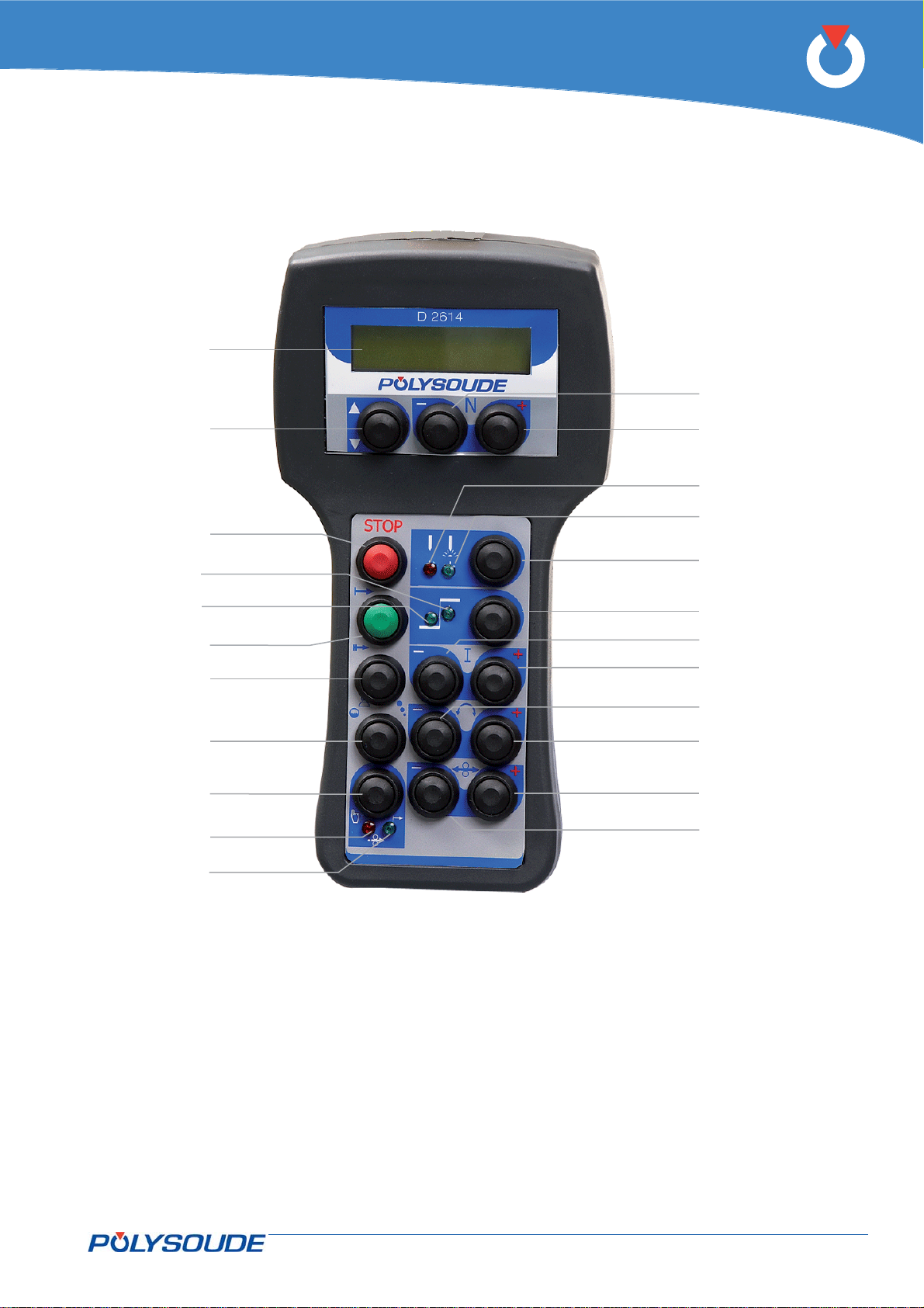
AF 1
P6
BT 2
BT 1
BT 16
V 3
V 4
BT 15
BT 14
BT 13
BT 12
V 5
V 6
BT 3
V 1
V 2
BT4
BT 5
BT 6
BT 7
BT 8
BT 9
BT 10
BT 11
Fig.4.27 - Remote control pendant 4 axis
PN-0509076 Rev. 16 51-92
THE ART OF WELDING
Page 52

P6
Display messages4. 5. 5. 1.
Examples of displayed messages out of weld cycle:
Switching on
-- POLYSOUDE ---
.....
End of installation
Example of fault message
During a gas and water fl ow rate test. The
message disappears when the button is
released to be replaced by the names of
the WP and the program.
Display during the end of a cycle
which has executed correctly.
Pressing BT 1 displays the end
of installation screen indicating
the WP and the program.
BT1
>WP :001IN170x15
PRG:<03ABCDEFG>
F r i 05 Jan 2007
11:49
WP : 001 IN170x15
PRG:<03ABCDEFG>
ROTATION: 04241
*!* Speed Regul
WP : 001 IN170x15
PRG:<03ABCDEFG>
Ga s 1 / 2 OK / NOK
Water= 0.8L/min
WP : 001 IN170x15
PRG:<03ABCDEFG>
S99 T0055s 0360 i
Cyc l e end OK
>WP :001IN170x15
PRG:<03ABCDEFG>
F r i 05 Jan 2007
11:49
.
WP : 001 IN170x15
PRG:<03ABCDEFG>
Display during the end of cycle
caused by the slope down key
(BT 13). Pressing BT 1 displays
the end of installation screen
indicating the WP and the
program.
52-92 PN-0509076 Rev. 16
BT1
>WP :001IN170x15
S05 T0015s 0124 i
Manua l d own s l ope
PRG:<03ABCDEFG>
F r i 05 Jan 2007
11:49
THE ART OF WELDING
Page 53
Examples of displayed messages during a weld cycle:
The display during a cycle shows:
on the fi rst two rows, the WP •
and the current program,
on the third row, the number of •
the current sector, elapsed time
and the movement pulses,
on the fourth row, 2 stars (1Hz) •
encircling an exclamation mark,
WP : 001 IN170x15
PRG:<03ABCDEFG>
S05 T0015s 0124 i
*!* 12.3V 150.0A
the arc voltage and welding current (I22).
P6
Changing a speed override erases
the fi rst two rows and displays the
new values sent. After 5 seconds,
the standard display shown during a
cycle reappears.
Changing a current override erases
the fi rst two rows and displays the
new values sent. After 5 seconds,
the standard display shown during a
cycle reappears.
A stop or slope down caused during
a cycle displays the corresponding
message.
V32=0125 mm/mi n
S05 T0015s 0124 i
*!* 12.3V 150.0A
I22=112 A
S05 T0015s 0124 i
*!* 12.3V 150.0A
WP : 001 IN170x15
PRG:<03ABCDEFG>
S05 T0055s 0360 i
Cyc l e end
PN-0509076 Rev. 16 53-92
THE ART OF WELDING
Page 54
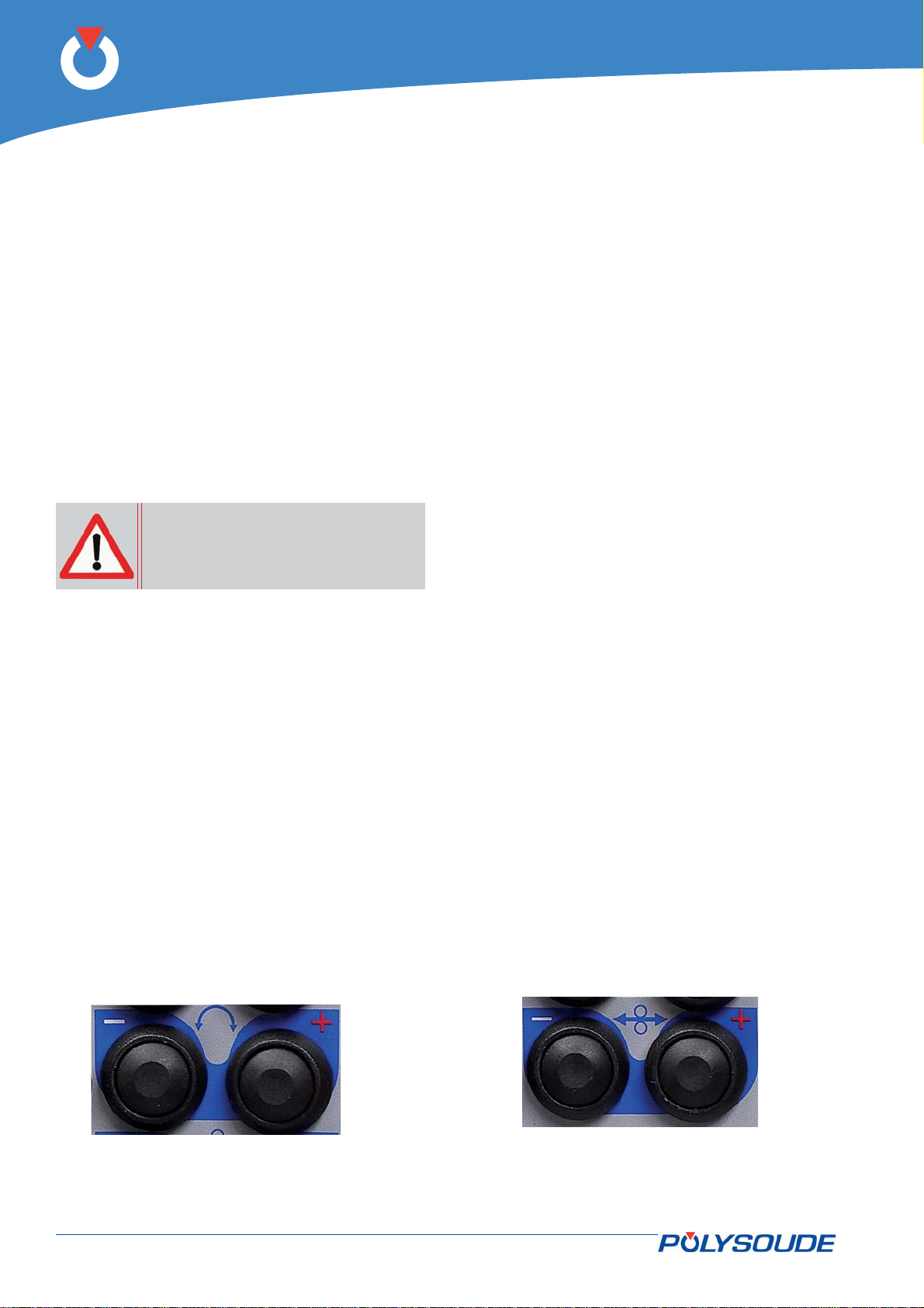
Operation of the power source P6 5.
P6
Fundamental procedures5. 1.
Switching on5. 1. 1.
With the installation connected (see chapter 4), set
the switch FA 1 (Fig. 4.17) to position 1. After a
short moment, the power source is powered up and
ready for operation. The remote control unit display
must show information on the WPs and programs.
Remark: If the power source is equipped with
the EMERGENCY STOP function, the operator
control unit must be connected to the P6, otherwise the latter will not power up.
In case of problems, see chapter 6.2 Maintenance.
After the power source has been
turned off by the switch FA 1, wait
for a time period of at least 15 seconds before turning it on again..
Automatic equipment detection5. 1. 2.
Depending on the date of fabrication, the power
source P6 can detect the type of connected welding
heads or wire feeding units automatically.
Positioning a welding head on the workpiece5. 1. 3.
To position a POLYSOUDE welding head on the
workpiece to be welded, consult the instructions
supplied with each head. With the welding head
in place, and before beginning the weld cycle, you
may move the electrode manually to wherever you
wish using the buttons BT 8 and BT 9 of the remote
control unit. Attention: with some closed chamber
welding heads the cycle cannot be started unless the
electrode is in the “open head” position.
The command is carried out in 3 stages: for 1 second
the rotation is made at low speed, then for 2 seconds
the rotation changes to medium speed, afterwards
it continues at high speed. This feature allows quick
and accurate positioning.
If the welding head is equipped with a contact to
detect its “open” position, manual rotation stops
when the “open” position is reached. Release the
button then press it again to continue rotation.
Wire setting5. 1. 4.
In combination with the «Manual/Automatic wire
mode» selected with switch BT 12 (V 5 and V 6), the
buttons BT 10 and BT 11 on the remote control unit
are used for accurate wire setting.
With the switch BT 12 in the «Auto» position, pressing BT 10 advances the wire, whereas pressing
BT 11 retracts it. The command is carried out in 3
stages: for 1 second the wire advances at low speed,
then for 2 seconds wire feeding changes to medium
speed, afterwards it continues at high speed. This
feature allows quick and accurate wire positioning.
To stop the wire, release the button.
With the switch BT 12 in the “Manual” position, the
function of the wire retract button BT 11 remains
as stated above, but BT 10 has a toggling function.
The fi rst press starts the wire feed in high speed,
the second press stops it. This feature is particularly useful for inserting fi ller wire into the wire-guide
sheath.
BT 8
Fig. 5.1 - Command buttons used for positioning
the electrode
54-92 PN-0509076 Rev. 16
BT 9
Fig. 5.2 - Command buttons used for wire setting
BT 11
BT 10
THE ART OF WELDING
Page 55
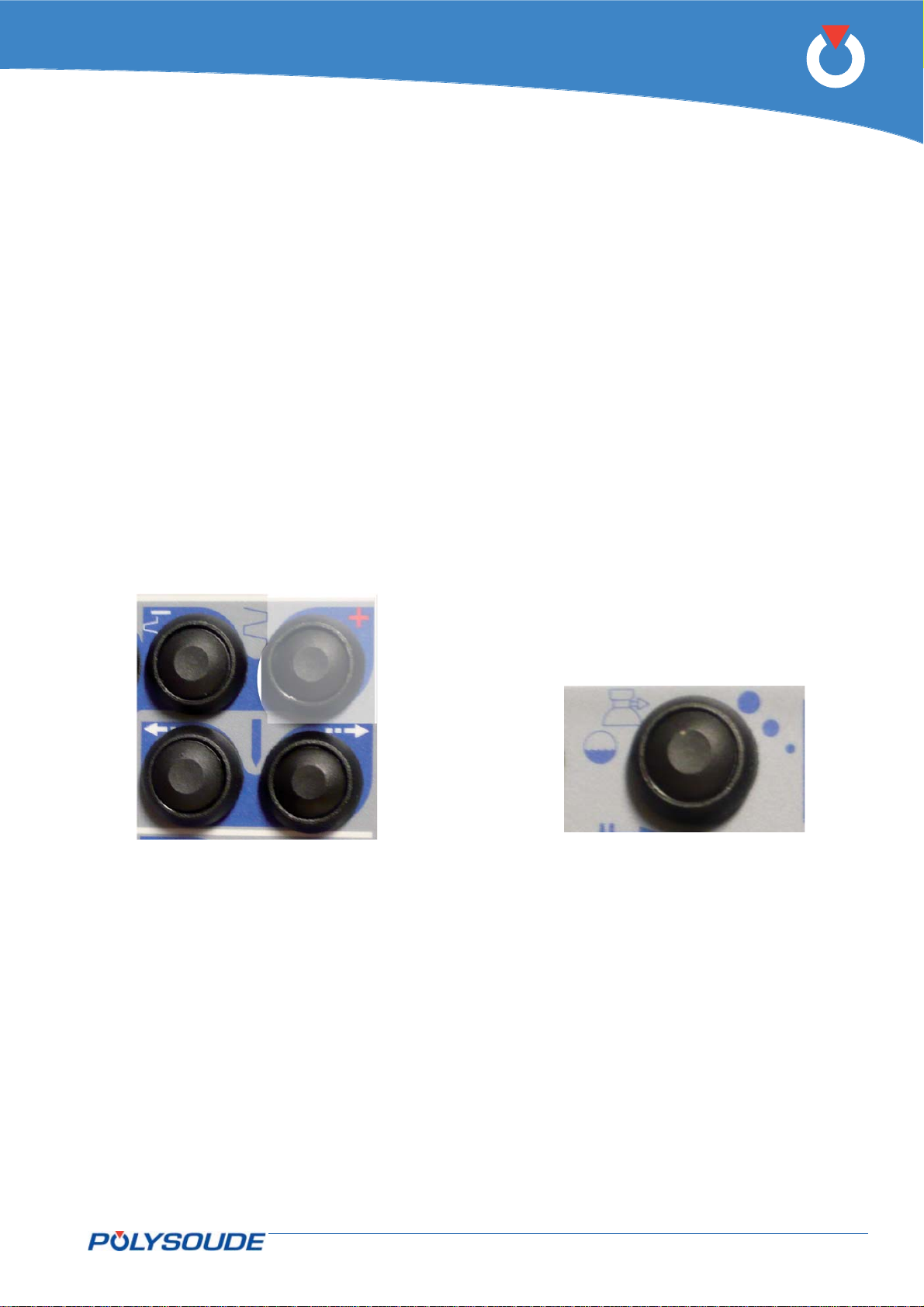
P6
Adjustment of the oscillation5. 1. 5.
To position the electrode in line with the joint use
BT 24 and BT 25 of the remote control unit. This
position is considered as the reference point for
the program. This operation is simplest for welding
without bevels. For welding with bevels and edges
it is possible to self-centre the torch. In order to do
this, position the torch between the two edges using
BT 22. Pressing BT 22 results in automatic centring
of the electrode by touching the sides. This implies
that the workpiece voltage measurement wire and
electrode must be connected.
BT 22
Adjustment of the gas fl ow5. 1. 6.
The gas fl ow is adjusted with a fl ow meter installed
on the gas bottle or the supply network. Pressing
BT 13 starts the gas fl ow manually.
Switching on the coolant pump 5. 1. 7.
manually
After changing a welding head, and particularly if
an extension cable is used, the coolant pipes may
be empty. Therefore a fault in the cooling system
may be detected when starting a cycle again. With
the button BT 13 the coolant pump can be switched
on to replenish the system before starting the next
cycle.
BT 24
Fig. 5.3 - Command buttons used to adjust the
oscillation
BT 25
BT 13
Fig. 5.4 - Push button for gas fl ow test - cooling
system test - and manual start of the
coolant pump
PN-0509076 Rev. 16 55-92
THE ART OF WELDING
Page 56
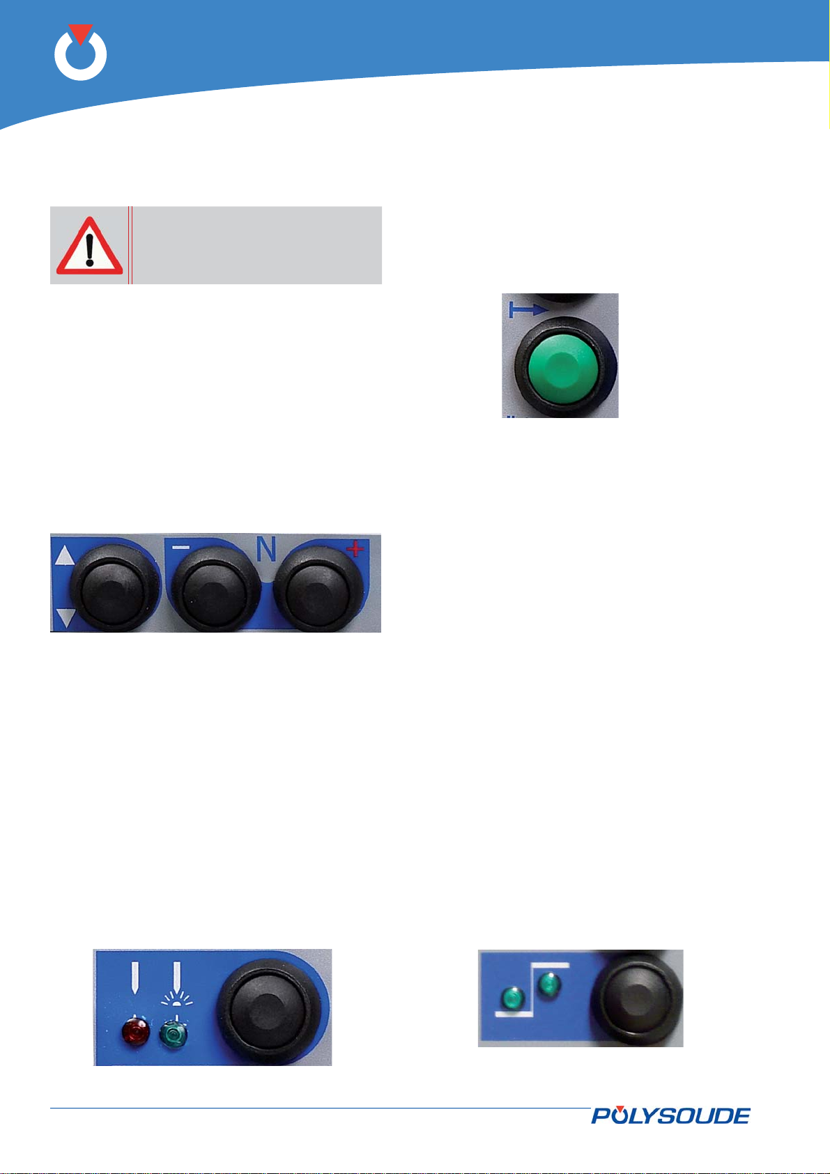
P6
Execution of a weld cycle5. 2.
Safety precautions5. 2. 1.
Before starting any manipulation
on the equipment please refer to
chapter 1 "Safety precautions".
Program selection5. 2. 2.
The WP and the program to be executed are selected
with BT 1, BT 2 and BT 3 on the remote control unit.
The names of the WPs and the program selected are
shown on the remote control unit display and on
the home page of the touchscreen. After 2 seconds
without operator action the WP or program is loaded
and can be used.
A long press (> 2 s) on button FA 16 will print out
the selected program.
Weld cycle5. 2. 4.
Start of a weld cycle
A weld cycle is started by pressing BT 15 on the
remote control unit.
BT 15
Fig. 5.7 - Weld cycle start push-button
Parameter modifi cations during a weld cycle
By means of the remote control unit, parameter modifi cations can be easily made during a weld
cycle.
BT 1
Fig. 5.5 - Command button used to select the
welding program
BT 2 BT 3
Simulation5. 2. 3.
To check the selected program without affecting the
workpiece to be welded, a simulation can be started.
In this case, all the functions of the program are
carried out except those concerning the arc.
The gas commands are executed as programmed
but any fl ow rate faults are not noted. So it is possi-
ble to check the fl ow adjustment or reduce the gas
consumption during the simulation. Selection of a
simulation is made with BT 4 which illuminates V 1.
BT 4
Parameters which can be modifi ed within each
sector:
The current (• I22) and/or the back ground current (I23) in the case of pulsed current.
The rotation speed • (V32) and/or the low rotation speed (V33) in the case of pulsed rotation.
The wire speed • (V42) and/or the low wire speed
(V43) in the case of pulsed wire.
The AVC (• H50) the height.
The oscillation • (T63) left edge delaying (T62)
right edge delaying (V60) the gap (A62) the
amplitude.
The modifi ed parameter values can be confi rmed
with BT 5 in conjunction with the 2 indicator lights
V 3 and V 4:
V 3• illuminated: Modifi cations of the low levels.
V 4• illuminated: Modifi cations of the high levels.
V 3• & V 4 illuminated: Modifi cations of the low
and of the high levels.
V 3
V 4
BT 5
Fig. 5.6 - “Simulation / With arc” indicator lights
56-92 PN-0509076 Rev. 16
Fig. 5.8 - BT5 push-button
THE ART OF WELDING
Page 57
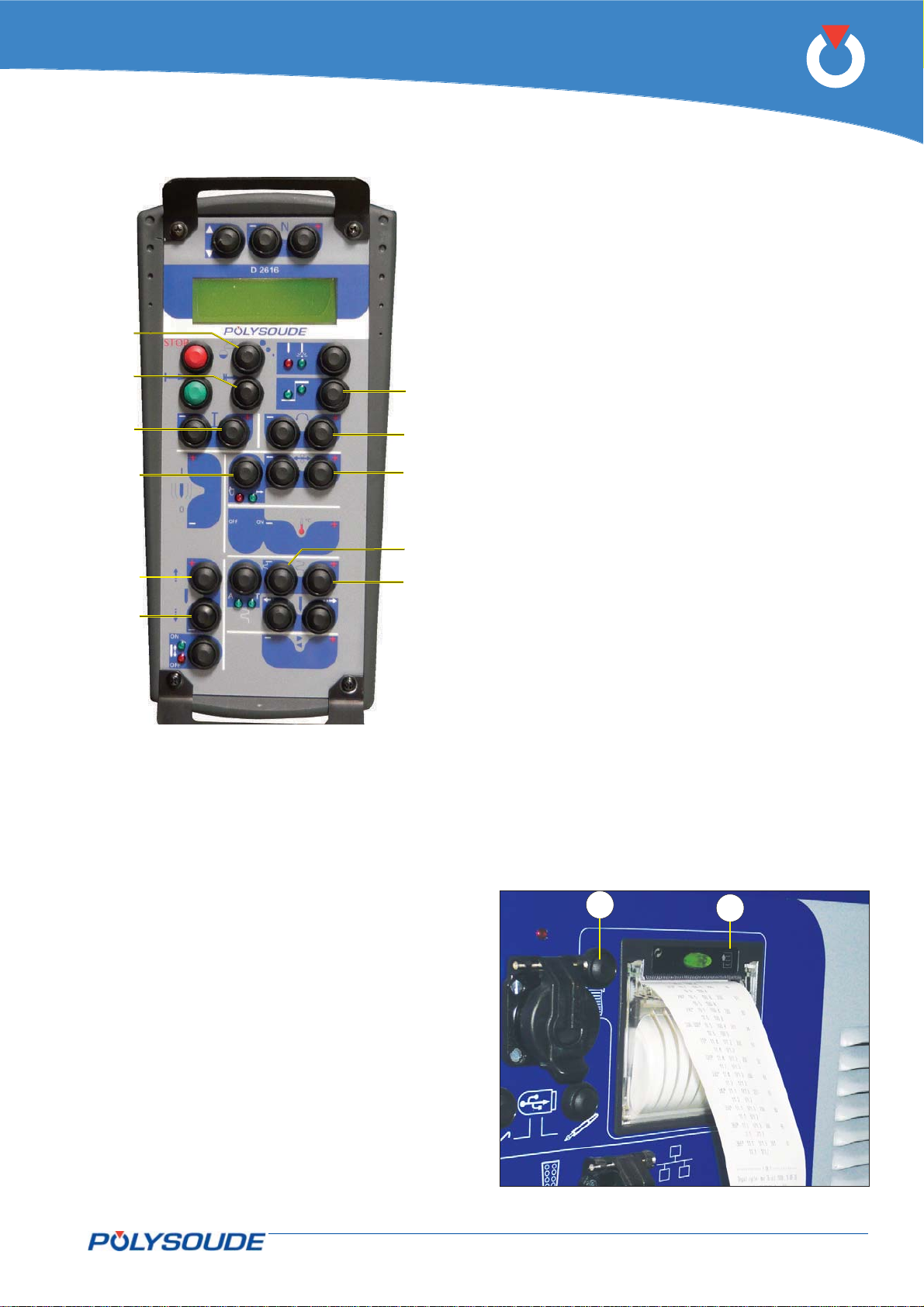
BT 13
BT 14
BT 7
BT 12
BT 18
BT 19
BT 5
BT 9
BT 10
BT 22
BT 23
Fig. 5.9 - "Delta" buttons for modifi cations of the
parameter values
P6
Stop at end of the weld cycle5. 2. 5.
Stop at end of a correct weld cycle
If the end of a correctly executed weld cycle is reached,
the message « Program end OK » is displayed on the
remote control unit. The power source is then ready
to start a new cycle.
Note: Welding heads equipped with a contact
to detect the “open head” position return automatically to this position if a correct end of
the cycle is reached.
Printing a weld cycle ticket
At the end of the weld cycle, you may print a ticket
summarising the weld performed.
On this ticket are:
The names of the WP and program.•
Values of current, voltage, rotation speed and •
wire feed speed measured regularly during the
cycle.
Reason for stopping («OK» for normal cycle, •
otherwise an error code).
Weld start time.•
Date of weld execution.•
Cycle duration.•
Movement effected.•
Reprinting a weld cycle ticket
If the printout of a weld cycle ticket at the end of a
cycle fails, for example because of a lack of paper, a
ticket for the last weld performed can be printed by
pressing FA 16 (Fig. 5-10 – Item 1) on the left side
of the printer.
For paper feeding, at the start or end of printing,
press the push button built into the printer (Fig. 5-10
– Item 2).
1
2
Fig. 5.10 - Print button and paper feeding
PN-0509076 Rev. 16 57-92
THE ART OF WELDING
Page 58
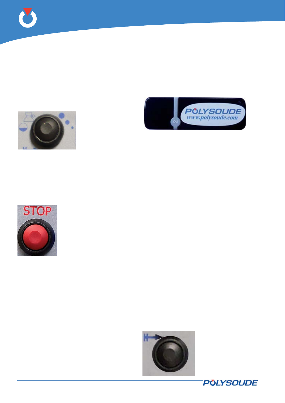
P6
Induced stoppage5. 2. 6.
Manual weld cycle stop with downslope
The downslope sequence determined in the program
can be started at any moment during weld cycle
execution by pressing BT 13 on the remote control
unit. This procedure prevents the workpiece from
being damaged during welding as far as possible.
The message “Manual downslope” is displayed on the
remote control unit.
BT 13
Immediate manual stop
If BT 16 on the remote control unit is pressed, the
arc is cut and all movements are stopped immediately. The post-gas fl ow is maintained during the
programmed time T25. The message ‘Manual stop’
is displayed on the remote control unit.
BT 16
Fig. 5.12 - Push-button for im-
Fig. 5.11 - Push-button
for cycle stop
with downslope
mediate stop
Use of an USB key5. 2. 7.
When the welding procedure is exported for the fi rst
time, a «Polysoude» folder is created in the root of
the USB key. If this is not the case, it is necessary to
create it in the root of the Polysoude key (x:/Polysoude).
Fig. 5.13 - Polysoude USB key
Start cycle with restart5. 2. 8.
Restart allows you to restart a weld when a cycle
was stopped under the following conditions:
Stop caused by manual slope-down•
Stop caused by a carrying out a «Stop»•
Stop caused by the appearance of a fault•
It is not possible to carry out a restart in the following cases:
The previous cycle fi nished correctly•
The restart is requested outside the welding •
area (0 > electrode position > N20)
Rotation had not started during the previous •
cycle
After changing a machine setting (WP setting, •
program setting, etc.)
After changing a program or WP.•
After a change via the GUI•
The start cycle with recovery can resume welding
parameter values corresponding to the position of
Using a manual torch
If a manual torch is connected to the power source
P6 as described at chapter 4.3.8, special functions
are available. A program from the set of special WP
for manual torches must be loaded. This program
disables all wire feed, AVC, Oscillation and rotation
movements.
Provided that the current selected in the welding
procedure is «Manual Pulsed», pressing on the torch
manual On button causes an arc to be struck. The
intensity of the ignition current is also the intensity
of the weld current. If the button is released, the high
current I22 is applied. Another press of the button
switches to the background current I23. Pressing
again switches back to I22, and so on. The cycle is
stopped either by pressing the downslope button, or
pressing both buttons at the same time will stop the
cycle immediately.
58-92 PN-0509076 Rev. 16
the electrode. Adjusting the position of the electrode
is made via the manual controls on the remote before
the start of cycle start with recovery.
During a restart:
The timer is reset to zero•
The pulse counter is set to the position at which •
the start is requested
The touch workpiece is rerun•
Pre-winding is not rerun.•
BT 14
Fig. 5.14 - Push button
start cycle with
restart
THE ART OF WELDING
Page 59
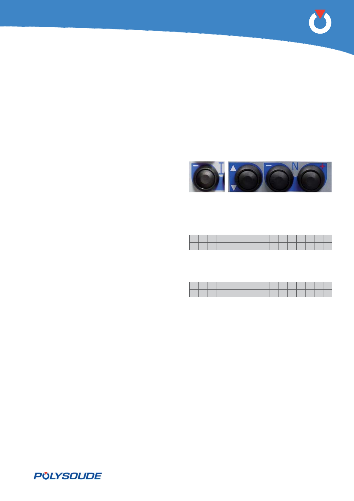
Servicing, maintenance and troubleshooting6.
Servicing 6. 1.
Adjustments6. 1. 1.
General
The following information concerns routine checks
and adjustments to be performed periodically or as
often as necessary.
These operations are not the same as calibrations
that have to be done periodically in order to satisfy
quality system requirements, according to ISO 9000
or Quality Assurance regulations.
These calibrations must be performed usinginspection equipment which has itself been calibrated in
accordance with written procedures by personnel
appointed for that purpose.
When to adjust?
Due to the ageing of components, a drift of the
source characteristics may occur gradually. Therefore it is recommended to check the power source
adjustments once a year.
Exchange of cards or the source
Adjustment is necessary after replacement of the
card 0028029300 or the source.
P6
Adjustment of the tachometer6. 1. 2.
If the power source is equipped with the optional
tachometer card, it is recommended to check whether
the programmed speed corresponds to the real travel
speed achieved by the rotation of the welding head.
The adaptation kit for the welding head connections
must be installed correctly. In home position a sign
should be marked as point of reference on the fi x part
of the welding head..
With the remote control pendant
BT 6
Press the button BT 6 “I-” of the remote control
pendant during several seconds.
On the display of the remote control pendant
appears:
>IPAdress
Tacho
Select “Tacho” with the button BT 1.
Confi rm the selection with the button BT 3 “N+”.
On the display of the remote control pendant
appears:
BT 1
BT 2
BT 3
Ca l i be r . Ta c ho
+:S t a r t . - :Qu i t
Press the button BT 3 “N+” again. The welding head
will now carry out a rotation of 360°. After the end
of the cycle, verify by means of the point of reference whether the rotation really stopped at 360°. If
the achieved result is correct, leave by pressing the
button BT 2 (N- = QUIT).
If the result is not o.k. adjust the travel speed of the
welding head with the corresponding potentiometer
(to identify the potentiometer, refer to the appropriate operating manual) and repeat the procedure until
the rotation stops correctly at the point of reference.
Verify the adjustment by carrying out a weld cycle in
simulation mode.
Using the GUI software (PC or touch screen)
Using the touch screen, program a 360° rotation and
start a weld cycle in simulation mode. After the end of the
cycle, verify by means of the point of reference whether the rotation really stopped at 360°. If the achieved
result is correct the welding can be carried out.
If the result is not o.k. adjust the travel speed of the
welding head with the corresponding potentiometer
(to identify the potentiometer, refer to the appropriate operating manual) and repeat the procedure until
the rotation stops correctly at the point of reference
PN-0509076 Rev. 16 59-92
THE ART OF WELDING
Page 60
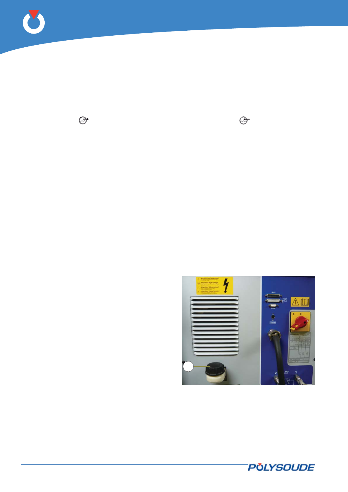
P6
Cooling circuit6. 1. 3.
The cooling circuit is equipped with a safety device to stop the actual weld cycle and to prevent the start of a
new one if the coolant temperature exceeds 80°C. A coolant level safety device prevents the start of a weld
cycle if there are less than 4 litres in the tank. If the level sinks below the limit during a weld cycle the safety
device does not trigger shut-down or downslope.
The coolant should be changed once a year. To do this, siphon off the old fl uid by placing a hose nozzle on the
water outlet (symbol
unit.
The circuit should be rinsed with pure water afterwards. The coolant tank is Refi lled through the orifi ce situated
on top of the power source (Fig.6.1 – item 1).
), and pressing the pump start button, BT 13 (symbol ) on the remote control
1
Fig. 6.1 - Refi ll the coolant
60-92 PN-0509076 Rev. 16
THE ART OF WELDING
Page 61
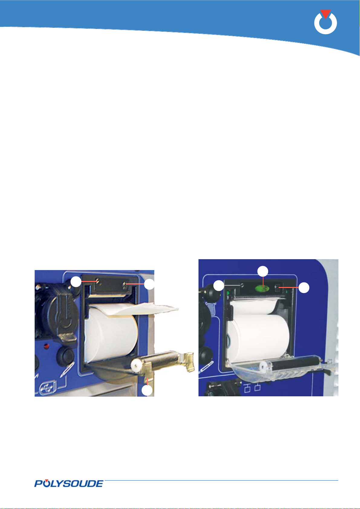
P6
Printer6. 1. 4.
Changing the printer paper
To change paper the power source must be switched on. Depending on the model of printer, change the roll
of thermal paper either by pulling down the two tabs of the cover (Fig.6.2 – Item 1) or by pressing the button
(Fig.6.2 - Item 4). Take out the empty roll and insert the new one so that the curve of the paper is at the inside
face of the printer and the start of the paper upwards.
Unwind enough paper so that after closing the cover a strip of paper appears at the outside.
To feed paper, push the button (Fig.6.2 - Item 2).
The green indicator light (Fig.6.2 - Item 3) is illuminated steady if the printer is ready to work; in case of a fault
or lack of paper, it fl ashes.
3
Fig. 6.2 - Printers
4
2
1
3
2
PN-0509076 Rev. 16 61-92
THE ART OF WELDING
Page 62
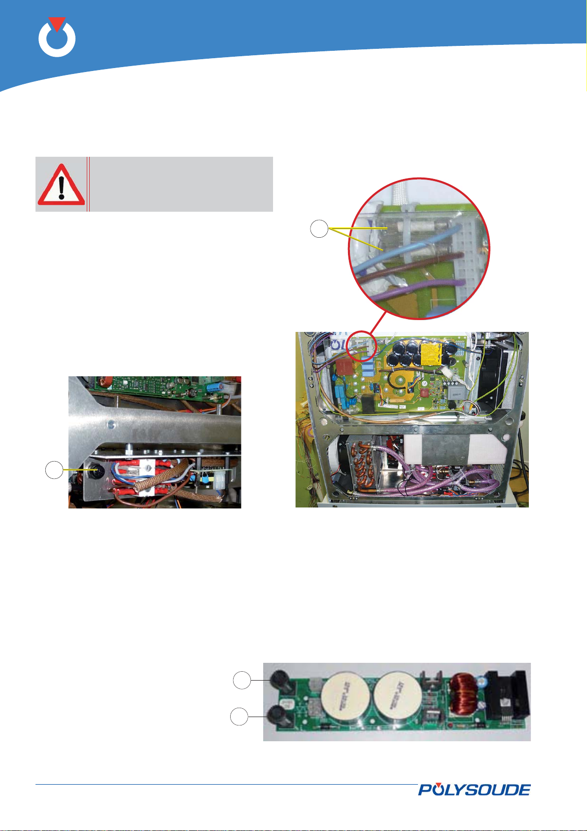
P6
Maintenance and troubleshooting 6. 2.
Replacement of fuses6. 2. 1.
Warning: a blown fuse often indicates
That there is a fault. Take great Care
when switching on the machine after
a fuse has been replaced.
The FU1 delayed action fuse 4 A (Fig.6.3 – item 1) for
the supply of all auxiliary devices is situated at the
lower left side of the power source.
The F1 and F2 delayed action fuses 6.3 A (Fig.6.4 –
item 1) for the primary power supply of the auxiliary
transformer are situated at the upper right side of the
power source.
1
1
Fig. 6.3 - Fuse FU1 location
Fig. 6.4 - Fuses F1 & F2 location
Fuses coolant pump control 6. 2. 2.
3 A timed fuses (Fig.6.5 - item 1) coolant pump control are at the end of the module "Interface pumps / motors
chokes" reference 0028229100.
1
1
Fig. 6.5 - Interface card Pumps / motors chokes
62-92 PN-0509076 Rev. 16
THE ART OF WELDING
Page 63
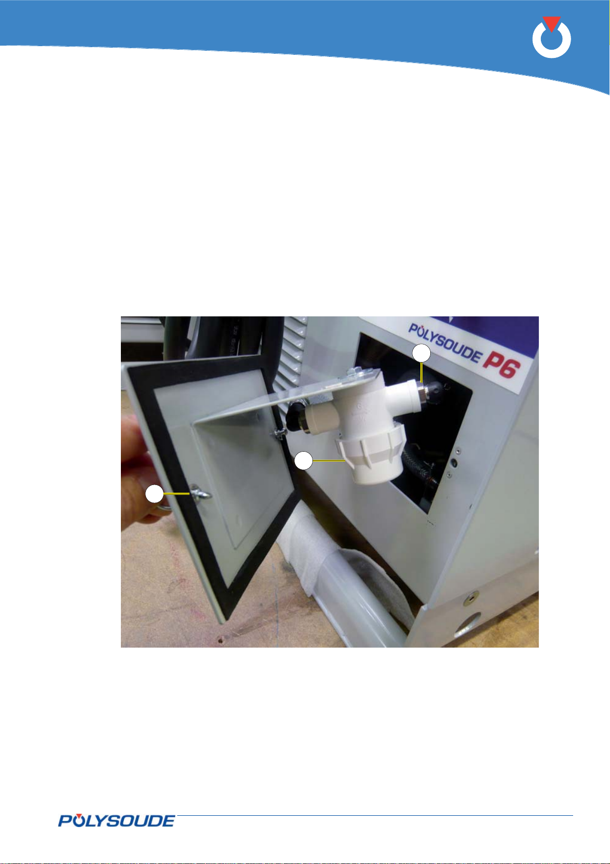
P6
Cooling circuit fi lter6. 2. 3.
The P6 power source is equipped with one or two fi lters in the cooling circuit(s) depending on the options select-
ed. The cleanliness of the fi lter cartridge should be checked every six months.
The fi lter element is accessible after undoing by a 1/4 turn the two fasteners securing the inspection hatch in
the rear panel. Place a container below the fi lter beforehand. Unscrew the transparent or white housing (Fig.6.6
– item 2) and take the fi lter element out for cleaning or replacement. For better accessibility, disconnect the two
unions by pulling the pressed fl ange (Fig.6.6 – item 3) upwards and lowering the two hose end-fi ttings.
3
2
1
Fig. 6.6 - Filter of the coolant
PN-0509076 Rev. 16 63-92
THE ART OF WELDING
Page 64

P6
64-92 PN-0509076 Rev. 16
THE ART OF WELDING
Page 65
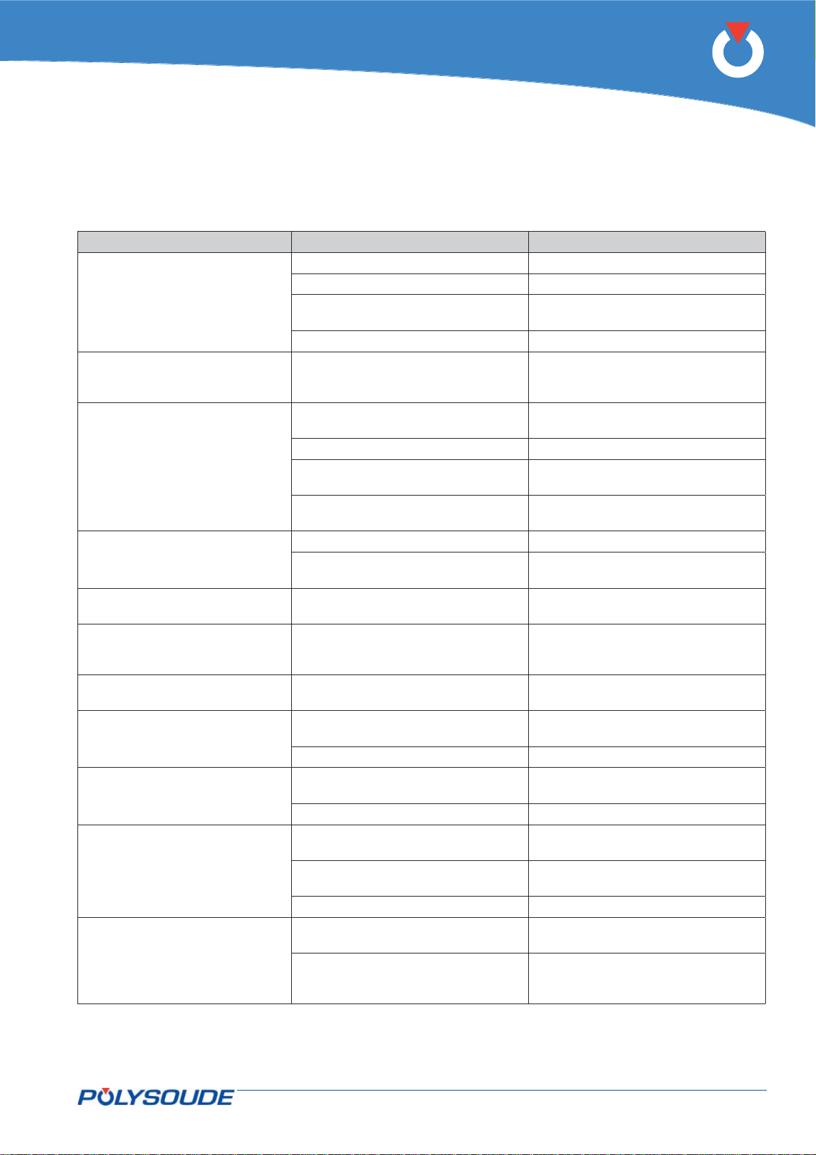
Trouble shooting6. 2. 4.
Defects occurring during operation
Problem (Consequence) Possible causes What to do
Fuse FU1 defect Change (chap. 6.2.1)
Impossible to switch the power
source on
Circuit breaker (outside the power
source) releases if the power
source is switched on
The cycle or a movement (rotation, wire, gas, cooling pump)
starts on its own
Some buttons of the remote control pendant are inoperative
No display on the remote control
or no backlighting
The parameter value cannot be
modifi ed (buttons "+" and "-"
inoperative)
Touchscreen is illuminated but
inoperative
Nothing displayed on the touchscreen
No cycle start possible with a
manual torch
Gas fl owrate too low
(Stop immediately)
No rotation (head or wire feed
unit) without error message
Plugs or mains supply cables defect Change
Remote control defect
(EMERGENCY STOP button locked)
Main switch defect Check or change
Unsuitable circuit breaker
The power source is not connected to
the earth
Remote control defect Check and repair or change
Cable shielding of the remote control
damaged
Remote control card 0028049100
defect
Remote control defect Check and repair or change
Remote control card 0028049100
defect
Remote control card 0028049100 or
display adapter 0028209200 defect
WP confi guration set to « modifi ca-
tions not allowed »
Touchscreen controller RS232 defect Contact Polysoude After Sales Service
Connector J17 on the card LVDS
0028069100 is unplugged
Card LVDS 0028069100 defect Replace
Bad connection of the manual torch
plug or wrong cabling
Wrong WP selected Select other WP
Gas channel inside the welding head
blocked
Gas safety device defect
Gas solenoid valve defect
Shear pin of the welding head or wire
feed unit broken
Power source converter cards
0028019100 (rotation and/or wire
feeding) defect
Check and correct or change
Install a circuit breaker of 20 A (with
D characteristic) for 400 V mains
supply (see rating plate)
Correct
Change the cable
Replace
Replace
Replace
Select other WP
Check
Check and correct
Check, clean
Must be checked and, if necessary,
replaced by a qualifi ed electrician
Replace (consult operating manual of
the head or the wire feed unit)
Replace
P6
PN-0509076 Rev. 16 65-92
THE ART OF WELDING
Page 66
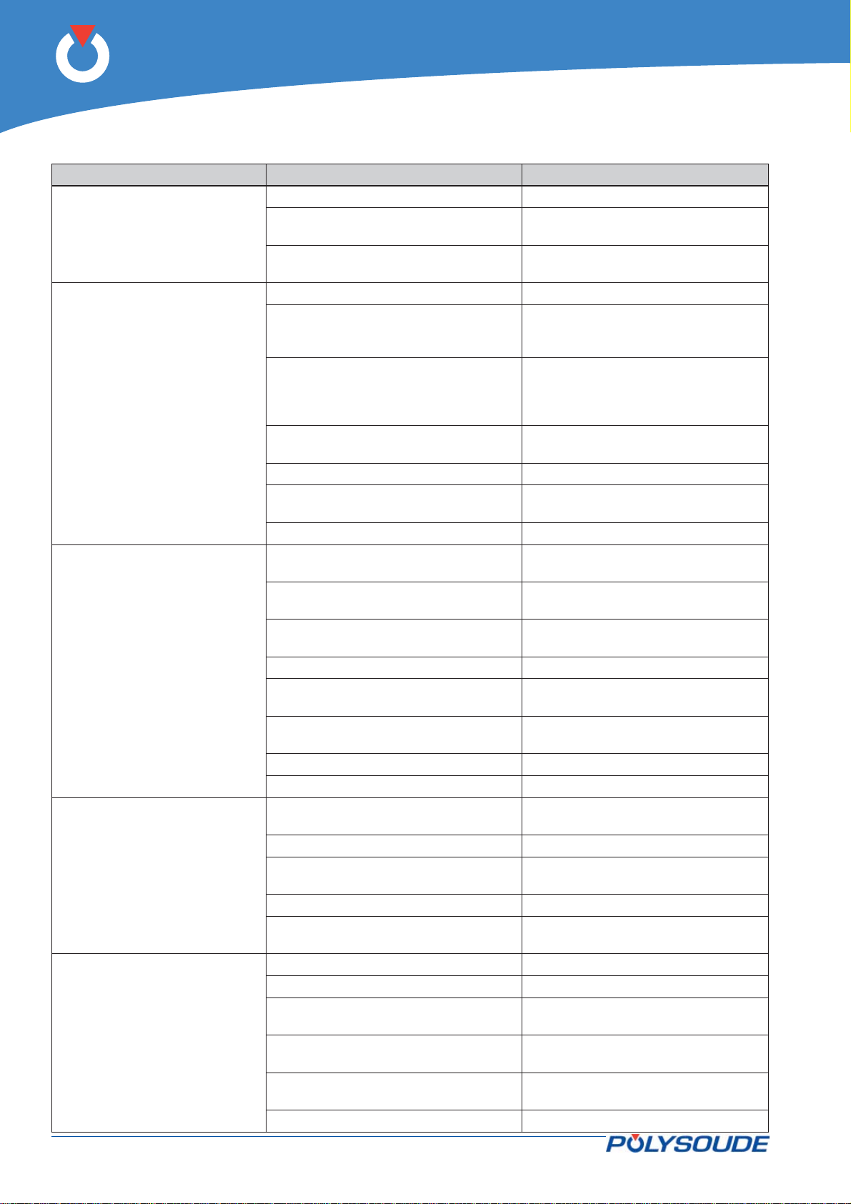
P6
Problem (Consequence) Possible causes What to do
Gas bottle empty or valve closed Check, replace or open
Gas
(Stop immediately)
Cooling circuit
(Imposed downslope)
Ignition
(Stop immediately)
Arc loss
(Stop immediately)
Short circuit
(Stop immediately)
Quick coupling of the welding head
badly connected
Solenoid valve defect
Coolant level too low Check and correct
Cooling circuit blocked
Shunt of the cooling circuit not connected (air cooled closed chamber
welding heads) - see power source
version
Quick couplings of the welding head
badly connected
Fuse defect Check and change (§ 6.2.1)
Pump defect
Polygaine defect (MU welding heads) Replace
Weld current cable badly connected or
cut
Earth connection not clamped at a
clean zone
Electrode contaminated or too far from
workpiece
Polygaine defect (MU welding heads) Replace
Ignition device not fi tted or badly posi-
tioned (welding heads MU, TP, TS …)
Gas not suitable, gas fl ow rate not
adapted
Power source badly adjusted Contact Polysoude After Sales Service
Current source defect Contact Polysoude After Sales Service
Electrode tip damaged or wrongly
prepared
Wrong distance electrode/workpiece Correct
Poor gas protection
Weld current programmed too low Correct
Ignition help mounted too near to the
torch (heads MU, TP, TS …)
Electrode touches workpiece Correct
Electrode touches fi ller wire Modify position of wire entry
Ignition device in contact with the
torch (heads MU, TP, TS …)
Bad insulation between wire guide and
torch
Interface card source 0028029100
defect
Current source defect Contact Polysoude After Sales Service
Check
Must be checked and, if necessary,
replaced by a qualifi ed electrician
Check, empty and clean the circuit,
clean the water fi lter. Fill up with
fresh coolant
Check and correct (§ 4.3.3)
Check and correct
Must be checked and, if necessary,
replaced by a qualifi ed electrician
Correct or replace
Move earth connection (§ 4.3.2 or
4.3.6)
Consult operation manual of the
welding head for electrode changing
Change position
Try with argon
Consult operation manual of the
welding head for electrode changing
Check fl ow rate, gas diffuser, clean,
correct
Correct the position
Correct the position
Check and correct
Replace
66-92 PN-0509076 Rev. 16
THE ART OF WELDING
Page 67
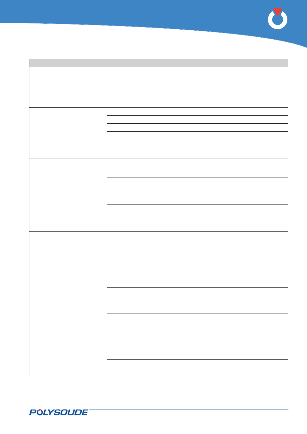
Problem (Consequence) Possible causes What to do
Respect a minimal distance between
Overheating
(Stop immediately)
Source control
(Stop immediately)
Rotation or wire feed control
(Stop or imposed downslope)
Overcurrent rotation or wire feed
(Stop immediately)
Rotation or wire feed pulse sensor
(Stop immediately)
Manual downslope
(Imposed downslope)
Manual stop
(Stop immediately)
End stop fault on oscillation/ Arc
height or touched part fault.
(Stop immediately)
Air circulation blocked
Power source capacity exceeded Modify conditions of use
Fan failure
Mains supply voltage too low Correct or modify the connection
Polygaine defect (MU welding heads) Replace
Power source badly adjusted Contact Polysoude After Sales Service
Current source defect Contact Polysoude After Sales Service
Sticky mechanics of the head or the
wire feed unit
Sticky mechanics of the head or the
wire feed unit
Power source converter card
0028019100 defect
Wire feed unit or head sensor damaged
Connection cable with the power
source damaged
Power source converter card
0028019100 defect
The power source is not connected to
the earth
Remote control defect Check
Cable shielding of the remote control
damaged
Remote control card 0028049100
defect
Remote control defect Replace
Remote control card 0028049100
defect
Surface of the workpiece in poor condition.
Connections on the +/- plugs are
wrong and arc voltage measurement on
the power source U
Voltage between workpiece and electrode less than 0.3 V when not welding
37 pin front connector (arc height/oscillation) not connected or cable damaged (item FA 27 in § 4.4.1.).
is wrong too.
arc
the openings and any surface (§
4.2.2), let the source cool down
Must be checked and, if necessary,
replaced by a qualifi ed electrician
Clean
Check for foreign bodies inside the
head or wire feed unit
Clean
Check for foreign bodies inside the
head or wire feed unit
Replace
Replace
Must be checked and, if necessary,
replaced by a qualifi ed electrician
Replace
Correct
Replace the cable
Replace
Replace
Improve the surface if it is possible
Connect properly and check
Check whether the voltage between
electrode and workpiece is higher
than 0.3 V when not welding. If not,
contact Polysoude After Sales Service.
Correct modify connections or change
the cable if it is damaged.
P6
PN-0509076 Rev. 16 67-92
THE ART OF WELDING
Page 68
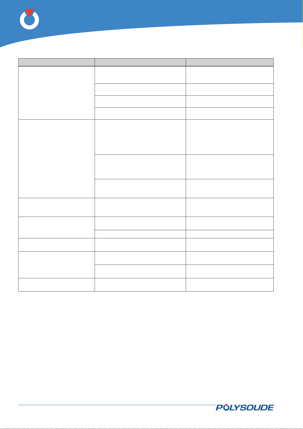
P6
Problem (Consequence) Possible causes What to do
Poor synchronisation between pulses
Fault of arc height regulation
(Stop immediately)
Start position
(Stop immediately)
Printer
(No printing)
Data backup
(No backup)
USB key empty
(No loading)
Reading or writing
(No recording or loading)
USB key full
(No recording)
of current, voltage, arc voltage, rotation, wire and oscillation.
Pulses too short for servo control to
arc voltage.
Insuffi cient sensitivity.
Connection of Uarc measurements
defective.
Closed chamber welding heads of the
type MW or H
The welding head is not in the open •
position
Head open detector switch is badly •
adjusted or defective
Other welding heads
Terminals D and E are not connected
together at the head rotation cable
connector.
In all cases
Power source converter card
0028019100 defect
Lack of paper or printer defect
The USB fl ash drive has been removed
before the end of the backup
No recording Refer to programming
No programs stored on the USB key Take a USB key with stored programs
Reading or writing error of the USB
key
The USB key has been removed before
the end of program backup
The USB key is full Erase a WP or take another USB key
Check or correct programming
Correct the values of parameters in
the welding program.
Check and correct the values of parameters in the welding program
Correct or modify connections or replace cable if damaged.
Modify the start position of the welding head
Check
Correct
Change
Load or replace
Start the backup operation again
Change the USB key
Start the backup operation again
68-92 PN-0509076 Rev. 16
THE ART OF WELDING
Page 69
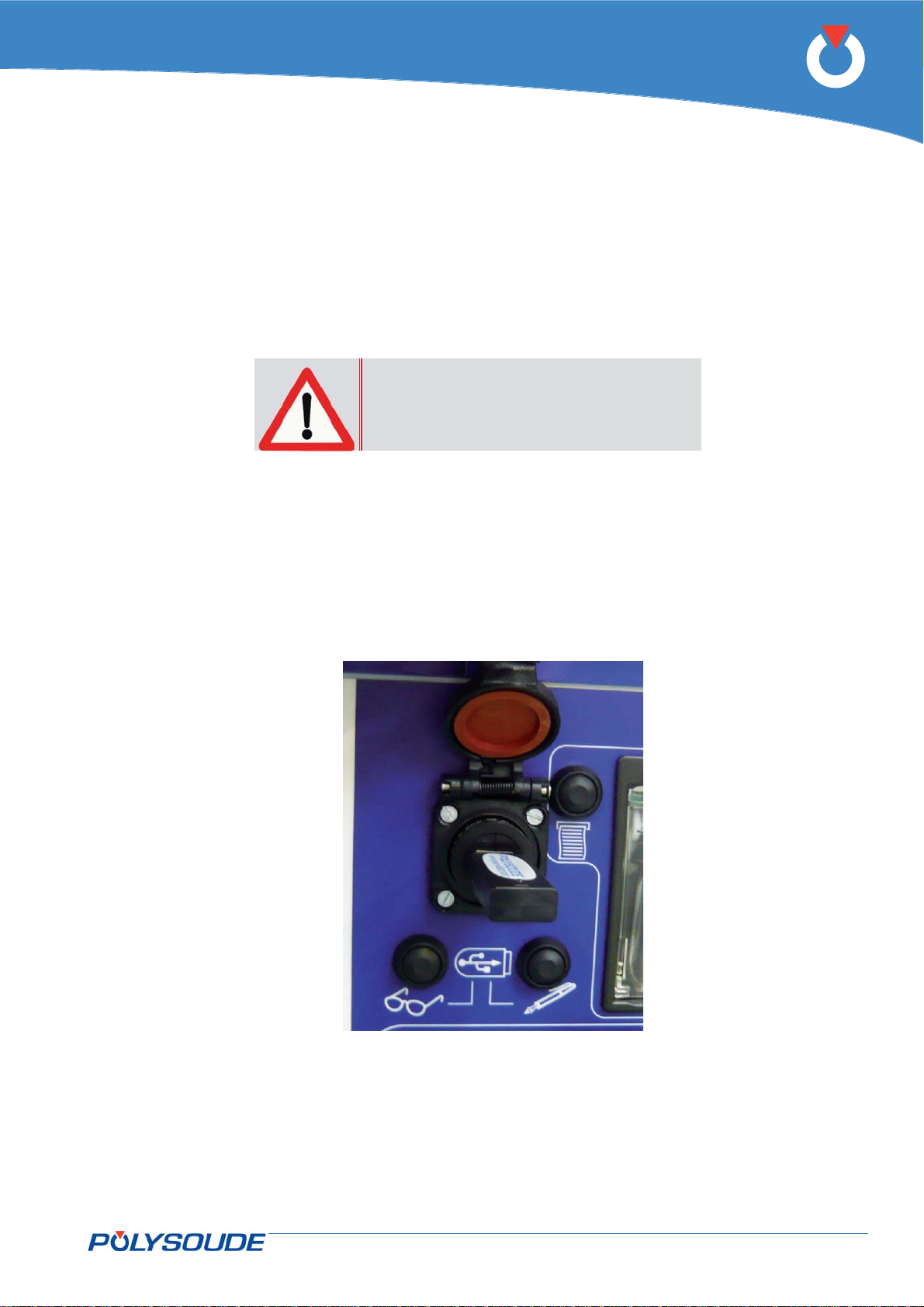
P6
Transfert of Log-fi les6. 2. 5.
To fi nd out the best solution in case of problems the so-called Log-fi les must be copied from the power source
and sent to the Polysoude After Sales Service. Logs fi les should be recovered as soon as possible after the onset
of the problem.
Necessary equipment :
1 empty Polysoude USB fl ash drive without any stored directories or fi les.
Copying of the Log-fi les :
To avoid loss of important fi les the pow-
er source must not be switched off when
the problem occurs.
If it had been switched off by mistake anyhow the following instructions shall be carried out to save the remaining fi les.
Connect the USB fl ash drive to the appropriate USB port.•
Push the button “Write on USB fl ash drive” at the front side of the power source, which is marked by a •
pencil symbol.
The fi le transfer from the power source to the USB fl ash drive is indicated by a fl ashing red LED.•
The red LED stops fl ashing when the fi le transfer has been fi nished (transfer time about 30 seconds).•
Disconnect the USB fl ash drive.•
Copy the directory named “Polysoude” with the transmitted fi les and send it per e-mail to the Polysoude •
After Sales Service.
Fig. 6.9 - Connector for USB-key
PN-0509076 Rev. 16 69-92
THE ART OF WELDING
Page 70

P6
Spare parts of the power source6. 2. 6.
Fig 6.10 to Fig 6.13
Item Reference no. Designation
1 00629085 Gas fl ow rate safety device
2 9000629198 Water fl ow rate safety device
3 9000629220 Water level safety device
4 9000629189 Water temperature safety device
5 9000699063 Coolant fi lter housing with stainless fi lter element
6 9000699064 Sieve fi lter element (stainless)
7 9000629170 Pump 24 V
8 9000629174 Gas solenoid valve 24 Vdc
9 0028009100 Sequencer 1 module and Sequencer 2 module
10 0028019100 Rotation or wire feeding module
11 0028029300 Source module
12 0028069100 LVDS screen module
13 0028279100 Source adapter
14 0028229100 Pump / motor inductor interface
9000629204 Source 300 A
9000629140 Switch self-holding (with EMERGENCY STOP)
9000629221 Switch (without EMERGENCY STOP)
15 9000629172 Fan 24 V DC
16 9000629184 Printer
17 00530054 Fuse FU1 (4 A)
9000530520 Fuse 6.3A x 500Vac
9000590068 Thermal paper roll 57 x 50
64599807 Ground cable AVC 70 mm², 9 m long
75110071 Coolant
75501002 Pressure-reducing valve with fl owmeter argon France
71701418 Pressure-reducing valve with fl owmeter argon Export
71701421 Pressure-reducing valve with fl owmeter argon/hydrogen
18 0028039100 AVC/oscillation module
19 0028079100 Arc voltage measurement module
9000532004 Fuse 3 A for module 0028229100
0023000901 A manual torch adaptater
70-92 PN-0509076 Rev. 16
THE ART OF WELDING
Page 71
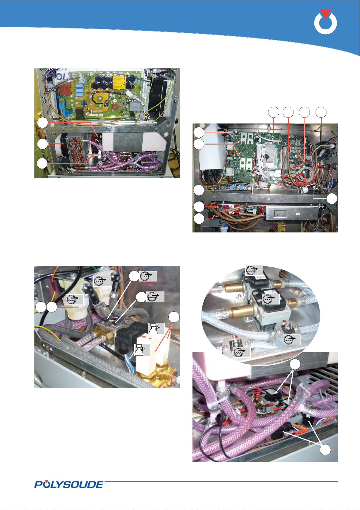
P6
12
9 1618
3
13
15
14
Fig. 6.10 - Internal view of the right side
1
2
546
4
10
11
19
17
8
Fig. 6.11 - Internal view of the left side
1
2
1
1
1
2
1
1
2
Fig. 6.12 - Internal view bottom right
Fig. 6.13 - Internal view bottom left
PN-0509076 Rev. 16 71-92
THE ART OF WELDING
2
7
2
Page 72
P6
Spare parts for P6 remote control6. 2. 7.
Fig 6.14 and Fig 6.15
Item Reference no. Designation
0026169101 Remote control complete 6 axis
0026149101 Remote control complete 4 axis
9000563323 Remote control plug
9000563326 Crimp contact for the plug
1 9000502015 Green indicator light
2 9000502019 Red indicator light
3 9000542083 Green button for the remote control
4 9000542082 Red button for the remote control
5 9000542081 Black button for the remote control
6 0028049100 Remote control module
7 0028209200 Display adapter
8 00503026 Display 4 x 20 characters
9 0028319100 Assembled fl exible card for P6 pendant
0026149110 Cable assembly (Spare remote control P4/P6)
72-92 PN-0509076 Rev. 16
THE ART OF WELDING
Page 73
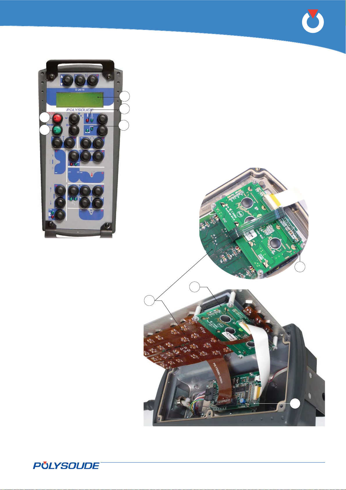
P6
8
2
4
3
1
Fig. 6.14 - Front of P6 remote
control
7
8
9
6
Fig. 6.15 - Internal view of the remote control
PN-0509076 Rev. 16 73-92
THE ART OF WELDING
Page 74
P6
Spare parts of the touchscreen6. 2. 8.
Fig 6.16
Position Reference no. Designation
1 0026119199 Touchscreen unit
2 9000623722 Touchscreen
3 9000623724 Screen SVGA LVDS 10.4’
4 9000623725 Backlight converter for the screen
5
6 0028239100 Interconnection card for the screen
7 0026119121 Cable power source / touchscreen link
9000623723 Touchscreen controller (old)
9000623790 Touchscreen controller (new 09/2013)
74-92 PN-0509076 Rev. 16
THE ART OF WELDING
Page 75
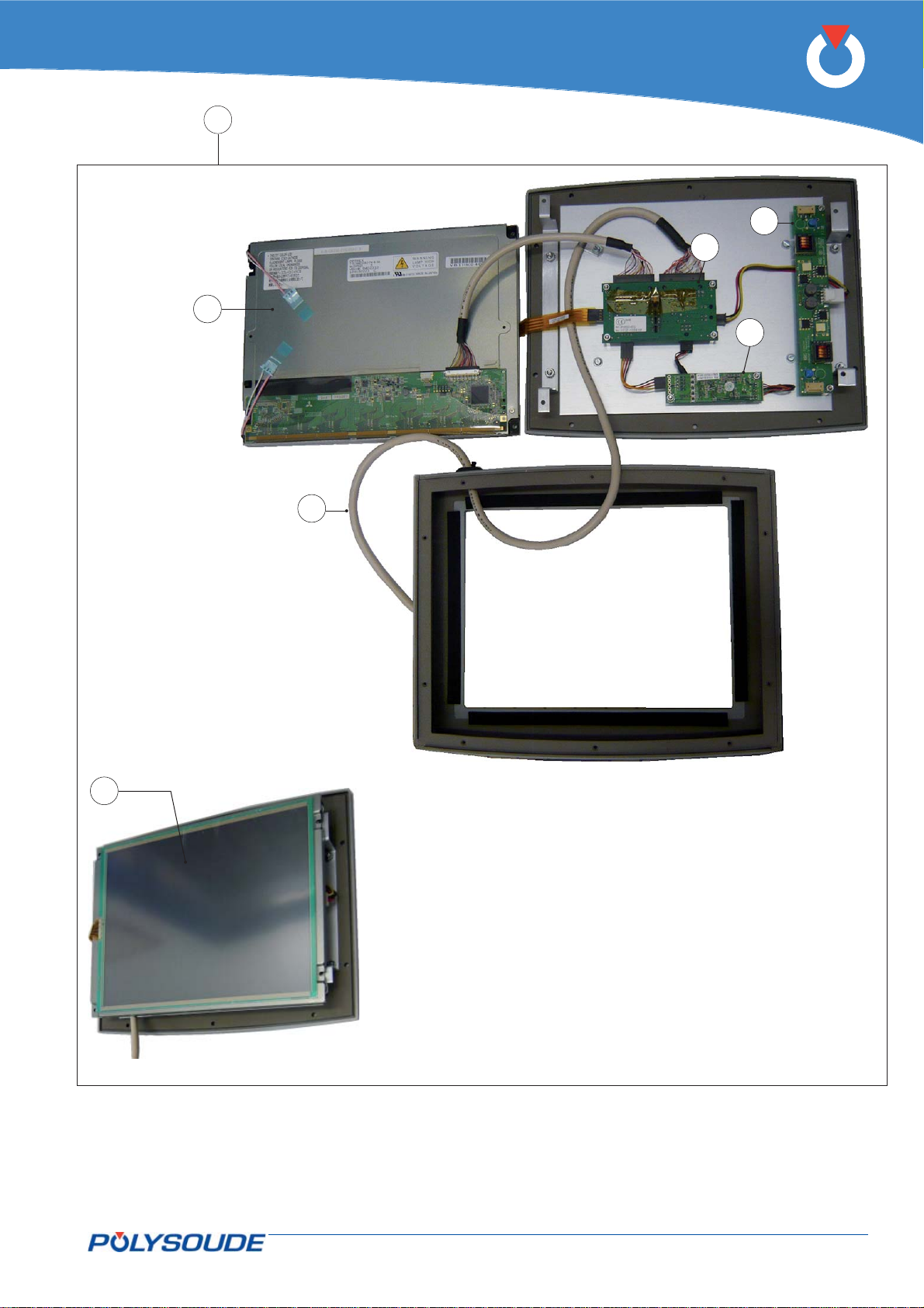
P6
1
4
6
3
5
7
2
Fig. 6.16 -Internal view of the touchscreen
PN-0509076 Rev. 16 75-92
THE ART OF WELDING
Page 76

P6
Electrical and electronic drawings6. 2. 9.
Warning
The following description is referenced to the folder
of the connection diagram of the power source P6
(Ref. 002505xxxx), and the others below:
remote control unit Ref. 002616xxxx
touchscreen Ref. 002611xxxx
sequencer card Ref. 002800xxxx
source interface card Ref. 002802xxxx
LVDS interface card Ref. 002806xxxx
rotation/wire feeding card Ref. 002801xxxx
AVC/oscillation card Ref. 002803xxxx
Arc voltage measurement card Ref. 002807xxxx
source adapter card Ref. 002827xxxx
inductor & pump interface Ref. 002822xxxx
touchscreen interconnection Ref. 002823xxxx
LCD/USB/RJ45 interconnection Ref. 002824xxxx
remote control keyboard Ref. 002825xxxx.
The signal names are abbreviations of their functions.
If the signal is active at low voltage (0 V), its name is
preceded by a slash (/).
On the block diagram, the number inside the frame
Fo:xy indicates the page number of the corresponding folder.
For the AVC/oscillation options, a second Sequencer
card, connected to the basis sequencer card, makes
it possible to controlboth speed control cards for the
AVC and oscillation motors (0028039100). The latter
are directly connected to sequencer card 2. The «arc
voltage measurement» card (0028079100) converts
the part/electrode voltage into digital signals through
an SPI serial bus to sequencer card 2.
The source
The current source is totally integrated and uses
“chopper” technology. The current setting, generated
by the source card, is an analogue signal from 0 V to
+10 V, where +10 V corresponds to 300 A.
A logic command, active at low level (0 V), commands
the source to switch on, and another logic command,
active at low level (0 V), controls the HF unit. If the
source overheats, the welding set orders stoppage of
the weld cycle.
The power source also outputs a display of the welding
current (+10 V corresponds to an actual 1000 A) and
of the welding set’s output voltage (+10 V corresponds to actual value of 100 V). These displays are
used for monitoring ignition, short circuits, and the
displays on the remote control or the touchscreen.
General description and wiring diagram
The various power supplies for the cards or components come from a sub-assembly providing 5 switching power supplies connections, operating from mains
voltages of 90 V to 260 Vac at 50 Hz or 60 Hz.
The basic functions of the P6 are realised by a PC
card of the PC104 standard, connected to the
sequencer card (0028009100). This sequencer card
is the main link between the commands issued by
the PC card and the signals for the controlled devices. In addition to the PC card, the sequencer card
is connected directly to the rotation and wire speed
control cards (0028019100) and to the command
card (0028069100) for the LVDS display and touchscreen. The source interface card (0028029300) is
connected via fl at cable to the sequencer. All of these
cards communicate via a 3-wire synchronous serial
SPI (Serial Peripheral Interface) bus. A single wire
enables several sources of information to be connected in parallel, such as welding head and wire feed
unit models, and the properties of welding set equipment.
76-92 PN-0509076 Rev. 16
THE ART OF WELDING
Page 77
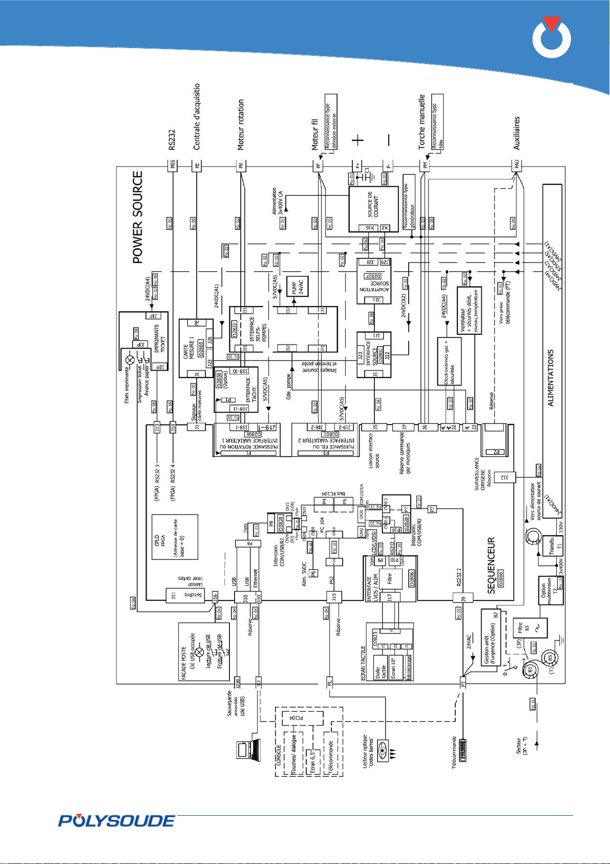
P6
Fig. 6.17 - Block diagram of the P6 power source
PN-0509076 Rev. 16 77-92
THE ART OF WELDING
Page 78
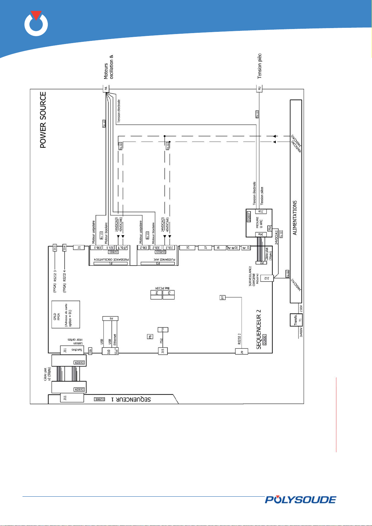
P6
Fig. 6.18 - Block diagram of AVC/Oscillation options
78-92 PN-0509076 Rev. 16
THE ART OF WELDING
Page 79
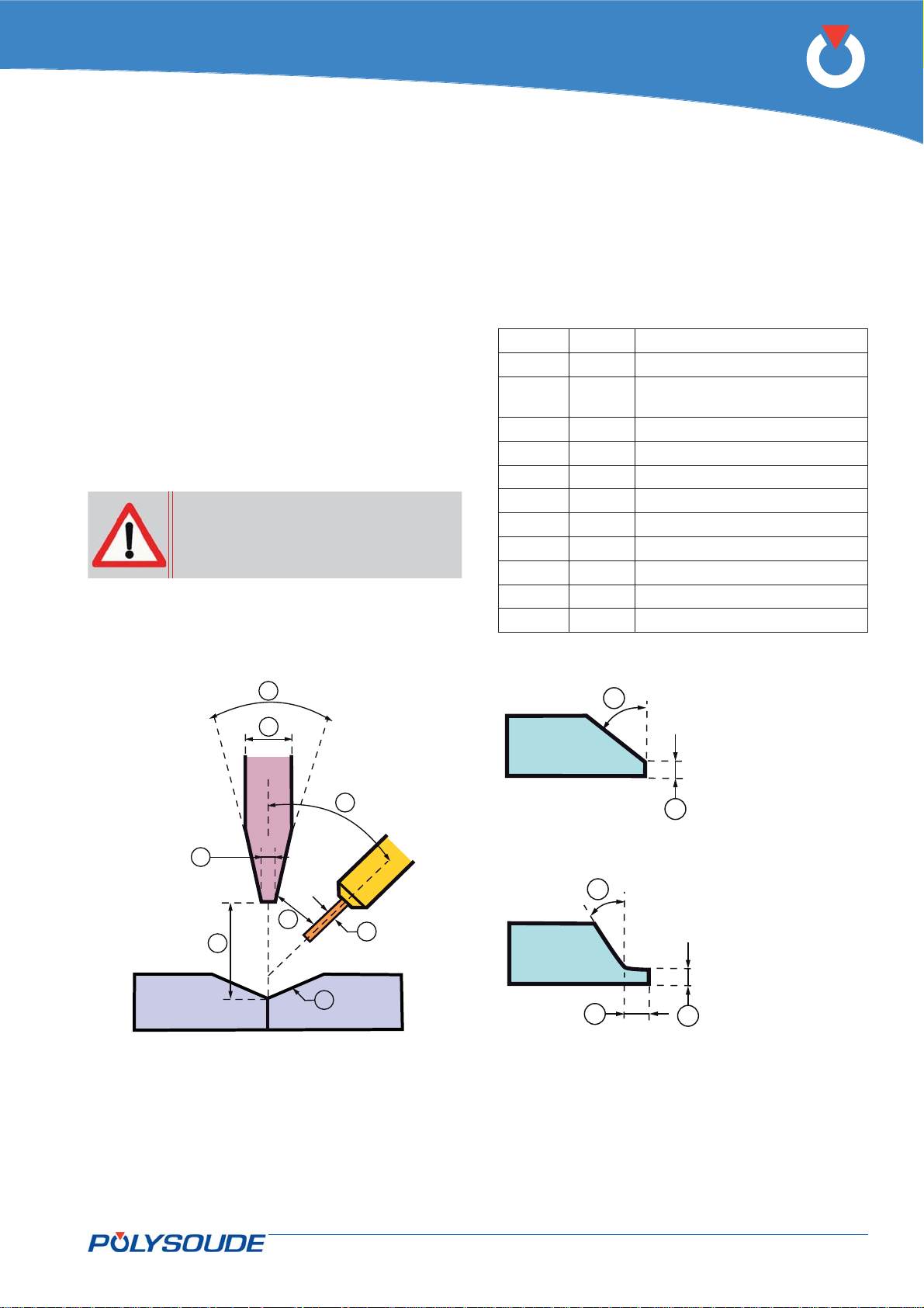
P6
APPENDIX7.
Pre-established WPs
The pre-established WPs (Welding Procedures) have
been developed by the Polysoude laboratory to allow
a fast approach to customised procedures. These WPs
correspond to frequently faced applications. Search
criteria are the name of the WP, the tube diameter,
the wall thickness, the base material, the application,
the type of welding head, the weld position; the P6
power source can offer you the pre-defi ned WP best
suited to the request. You are then able to modify
this user WP to refi ne the welding procedure.
All WPs are intended to be executed with argon as
shielding gas.
Warning: Some applications require
two or more programs.
All programs that use fi ller wire have been developed
with wire of 0.8 mm diameter.
The result and the quality of a weld is infl uenced
considerably by non-programmable adjustments. In
the pre-defi ned WPs you will fi nd the values chosen
as each program was generated. The parameters
are:
Fig.7.1 Item 1 Tube end preparation.
Fig.7.1 Item 2 Electrode diameter.
Fig.7.1 Item 3 Sharpening angle of the elec-
trode.
Fig.7.1 Item 4 Flattened tip of the electrode.
Fig.7.1 Item 5 Distance electrode/workpiece.
Fig.7.1 Item 6 Filler wire diameter.
Fig.7.1 Item 7 Filler wire outlet angle.
Fig.7.1 Item 8 Distance electrode/wire.
Fig.7.1 Item 9 Star position of the weld.
Fig.7.2 Item 10 Preparation angle.
Fig.7.2 Item 11 Land thickness.
Fig.7.2 Item 12 Land length in case of a J prep.
3
2
7
4
8
5
6
1
10
12
10
11
11
Fig. 7.1 - Some non-programmable parameters Fig. 7.2 - Tube end preparations
V preparation
J preparation
PN-0509076 Rev. 16 79-92
THE ART OF WELDING
Page 80
P6
Error and codes processing7. 1.
Cause Code Fault Consequence
4097 Gas fl owmeter not present (1) Stop
Gas
Cooling
Voltage 4161
Current
Rotation
4465 Oxygen error (1) Stop
4673 Oxygen error (2) Stop
4529 Gas fl owmeter not present (2) Stop
4113 Cooling fl owmeter not present (1) Imposed downslope
4129 Cooling level too low (1) Stop
4145 Cooling temperature too high (1) Imposed downslope
4513 Cooling fl owmeter not present (2) Imposed downslope
4193
4177 Arc loss Stop
4209
4225 Troubles on supply voltages Stop
4241 Control of rotation speed Stop
4273
4449 Start open welding head Stop
Short-circuit
Ignition impossible
Power supply temperature too high
(Overheating)
Rotation overcurrent (Rotation motor
blocked)
Stop
Stop
Stop
Stop
Wire
Hot wire 4625 HW error Imposed downslope
Power source
Arc voltage control
(AVC)
Oscillation
4257 Control of wire speed Imposed downslope
4289 Wire overcurrent (Wire motor blocked) Stop
4305 Priority stop Stop
4321 Overvoltage
4337 Undervoltage
4353 Priority stop requested (software)
4369 Control system Stop
4417 Wrong detection of equipment No cycle start
4433
4481 Impossible restart No restart
4497 GUI problem
4577 High end stop reached Stop
4593 Low end stop reached Stop
4545 Right end stop reached Stop
4561 Left end stop reached Stop
Welding head detection impossible with
extension
Variator
80-92 PN-0509076 Rev. 16
4689 Variator not ready (absent) Stop
4705 variator connection impossible Stop
THE ART OF WELDING
Page 81
P6
List of programmed welding parameters7. 2.
Gas axis
Function Wording Ref. Min. Max. Unit Increment Default
Prepurge time Pregas time T10 1.0 999,0 s 0.1 10.0
Postpurge time Postgas time T11 1.0 999,0 s 0.1 10.0
Oxygen fl ow rate control
Current axis
Oxygen
threshold
L10 1.0 206400 ppm 0.1 50.0
Function Wording Ref. Min. Max. Unit Increment Default
Ignition current Ignition current I20 5 300 A 1 25
Prefusion ramp time Ramp time T20 0 9999 s 1 0
High current High current I22 5.0 300.0 A 0.1 10
High current time Pulse time high T22 0 or 10 3000 ms 1 100
Low current Low current I23 5.0 300.0 A 0.1 5
Low current time Pulse time low T23 0 or 10 3000 ms 1 100
Start of downslope Start downslope N20 361 9999 ° 1 365
Downslope time Downslope time T25 0.1 60.0 s 0.1 3.0
Arc cut-off current
Arc cut-off
current
I25 5 300 A 1 5
PN-0509076 Rev. 16 81-92
THE ART OF WELDING
Page 82
P6
Rotation axis
Function Wording Ref. Min. Max. Unit Increment Default
Prerotation time
Pre-rolling Angle N30 0 9999 ° 1 0
Tube diameter to be welded Diameter D (a) (a) mm 0.1 (a)
Rotation ramp time Ramp time T31 0.0 99,0 s 0.1 0
Rotation speed (high) Speed V32
Rotation speed (low) Speed V33
Prerotation
time
T30 0.0 60.0 s 0.1 3
0 (b)
then (c)
0 (b)
then (c)
0 (b)
then (c)
0 (b)
then (c)
0 (b)
then (c)
0 (b)
then (c)
(c)
(c) in/min 0.01 (c)
(c) tr/min 0.001 (c)
(c)
(c) in/min 0.01 (c)
(c) tr/min 0.001 (c)
mm/
min
mm/
min
1 (c)
1 (c)
Wire axis
Function Wording Ref. Min. Max. Unit Increment Default
Start delaying Pre-wire time T40 0.0 60.0 s 0.1 4
Speed or
Wire speed
Wire speed (low current) Low wire speed V43
Delaying of wire feeding
stop
Wire retract time at the end
of cycle
Ramp time Ramp time T44 0.0 9999,0 s 0.1 0
Ramp time Downslope Ramp time T45 0,0 9999,0 s 1 0
(a) depending on type and model of the welding head minimum and maximum values differ.
(b) because of gliding losses at each stop a speed pulsed at 0 can cause a cumulated error. In the case, the
observed displacement depending on th pulse frequency and speed must be added to the program.
(c) minimum and maximum speeds are calculated depending on type and model of the used welding head and
on the diameter of the tubes to be welded.
(d) speeds and amplitudes depend on on the wire feeder or slides.
High wire
speed
Stop wire
Wire retract
V42
N40 0 9999 ° 1 360
T41 0.0 9,9 s 0.1 2
0 then
(d)
0 then
(d)
0 then
(d)
0 then
(d)
(d)
(d) in/min 0.1 (d)
(d)
(d) in/min 0.1 (d)
mm/
min
mm/
min
1 (d)
1 (d)
82-92 PN-0509076 Rev. 16
THE ART OF WELDING
Page 83
P6
Arc voltage control axis – AVC (option)
Function Wording Ref. Min. Max. Unit Increment Default
Delay before start AVC leadtime T50 0.0 999,0 s 0.1 5,0
Ignition height Height H50
Torch height regulation
speed
AVC sensitivity Sensitivity S50 1.0 20.0 / 0.1 5
Activate Stop AVC Position N50 0 9999 ° 0 365
Arc voltage (pulse current
or background current at
thermal pulsing)
Ramp time Ramp time T51 0.0 999,0 s 0.1 0
Arc voltage (pulse current
at thermal pulsing)
Arc voltage (background
current)
Time Blocage front T54 10 250 ms 1 10
Height torch retract Height
Speed V50
High voltage H51 (e) (e) V 0.1 (e)
H52 (e) (e) V 0.1 (e)
Low voltage H53 (e) (e) V 0.1 (e)
H54 (e) (e) mm 1 (e)
(e) (e) mm 1 (e)
(e) (e) in 0.001 (e)
(e) (e)
(e) (e) in/min 0.01 (e)
(e) (e) in/min 0.1 (e)
mm/
min
0.1 (e)
Oscillation axis – OSC (option)
Function Wording Ref. Min. Max. Unit Increment Default
Delay before start
Offset Gap E60
Oscillation speed Speed V60
Speed Speed V61
Oscillation width Amplitude A62
Right edge delaying Right edge
Left edge delaying Left edge de-
Ramp time Ramp time T64 0.0 99,9 s 1 0
Preoscillation
time
delaying
laying
T60 0 40 s 0.1 5
(e) (e) mm 0.1 0
(e) (e) in 0.01 0
(e) (e)
(e) (e) in/min 0.1 (e)
(e) (e)
(e) (e) in/min 0.01 (e)
(e) (e) mm 1 (e)
(e) (e) in 0.01 (e)
T62 0.1 9.9 s 0.1 0.3
T63 0.1 9.9 s 0.1 0.3
mm/
min
mm/
min
1 (e)
0.1 (e)
(e) the parameter values (speed, amplitude, voltage, etc.) depend on the equipment.
PN-0509076 Rev. 16 83-92
THE ART OF WELDING
Page 84

P6
84-92 PN-0509076 Rev. 16
THE ART OF WELDING
Page 85

P6
End of service life, recycling the equipment8.
Our equipment incorporates electrical and electronic components which must be collected in accordance with
Directive 2002/96/CE. Any item of equipment which is declared obsolete or out of service must be sent to
approved recycling companies in order to reduce the amount of ultimate waste disposal. A number of solutions
may be deployed, including:
Re-use,•
Recycling,•
Any other form of recovery (including energy recovery) of WEEE (Waste from Electrical and Electronic •
Equipment).
PN-0509076 Rev. 16 85-92
THE ART OF WELDING
Page 86

P6
86-92 PN-0509076 Rev. 16
THE ART OF WELDING
Page 87
RETURN OF EQUIPMENT
(Please fill out and join this sheet when returning equipment to POLYSOUDE)
Returned equipment form9.
Reseller / Person in charge :
Customer / Person in charge / Tel. :
EQUIPMENT RETURNED :
Power source Type : Serial number :
Welding head Type : Serial number :
Wire feeder Type : Serial number :
Other (specify designation) :
taken from :
Power source Type : Serial number :
P6
Welding head Type : Serial number :
Wire feeder Type : Serial number :
Other(to be specified) : Serial number :
REASON FOR RETURN :
Return of loan equipment
Return of demonstration / fair equipment
Return of hired equipment
Return after exchange
Deficient delivery / incorrect order
Return for modification (to be specified) :
Return for revision
Return for calibration
Return for repair
to be specified : systematically occurring error
occasionally occurring error
Description of breakdown
:
Other issue (to be specified) :
Date : Signature:
SAV_FOR_011_Return of equipment_REV_03
PN-0509076 Rev. 16 87-92
THE ART OF WELDING
Page 88

P6
Table of illustrations
Fig. 3.1 - P6 HW power source ........................................................................................... 12
Fig. 3.2 - P6 power source ................................................................................................. 13
Fig. 3.3 - P4 power source ................................................................................................. 13
Fig. 3.4 - MU IV welding head ............................................................................................ 16
Fig. 3.5 - Polycar welding carriage ...................................................................................... 16
Fig. 3.6 - MW welding head ................................................................................................ 16
Fig. 3.7 - TS 34 welding head ............................................................................................. 17
Fig. 3.8 - TS 2000 welding head ......................................................................................... 17
Fig. 3.9 - TS 8/75 welding head .......................................................................................... 17
Fig. 3.10 - Polyfi l-3 wire feeder .......................................................................................... 17
Fig. 3.11 - Description of P6 power source ........................................................................... 18
Fig. 3.12 - P6 remotes control unit ...................................................................................... 19
Fig. 4.1 - Accessories supplied with the power source P6 ....................................................... 21
Fig. 4.2 - Rating plate of the P6 power source ...................................................................... 22
Fig. 4.3 - Transformer coupling ........................................................................................... 23
Fig. 4.4 - Layout of coupling terminal block .......................................................................... 23
Fig. 4.5 - Connection of the gas supply to the power source P6 ............................................... 25
Fig. 4.6 - Connection diagram if one gas is used ................................................................... 25
Fig. 4.7 - Connection diagram if two different gases are used ................................................. 25
Fig.4.8 - Memo Axis confi guration standard .......................................................................... 29
Fig. 4.9 - Connection of the remote control unit to the P6 power source ................................... 30
Fig. 4.10 - Connection of an open welding head of the MU type or a tube/tubesheet welding
head of the type TS or TP................................................................................... 33
Fig. 4.11 - Connection of a gas cooled closed chamber welding head ....................................... 31
Fig. 4.12 - Connection of a liquid cooled closed chamber welding head .................................... 34
Fig. 4.13 - Connection of a liquid cooled closed chamber welding head with integrated com-
mand buttons ................................................................................................... 35
Fig. 4.14 - Connection of a wire feed unit............................................................................. 36
Fig. 4.15 - Connection of a closed chamber welding head equipped with tacheometry ................ 37
Fig. 4.16 - Connection of a manual torch ............................................................................ 38
Fig. 4.17 - Power source rear connection panel and oxygen meter ........................................... 40
88-92 PN-0509076 Rev. 16
THE ART OF WELDING
Page 89

P6
Fig. 4.18 - Power source rear connection panel .................................................................... 41
Fig. 4.19 - Modules .......................................................................................................... 41
Fig. 4.20 - Ethernet swtich and power supply ...................................................................... 41
Fig. 4.21 - Remote control unit with emergency stop ............................................................. 41
Fig. 4.22 - Connector wiring ............................................................................................... 42
Fig. 4.23 - Front connector panel ....................................................................................... 45
Fig. 4.24 - Rear connector panel ......................................................................................... 46
Fig. 4.25 - Quick connector gas input .................................................................................. 47
Fig. 4.26 - Remote control unit 6 axis .................................................................................. 49
Fig.4.27 - Remote control pendant 4 axis ............................................................................. 51
Fig. 5.1 - Command buttons used for positioning the electrode ............................................... 54
Fig. 5.2 - Command buttons used for wire setting ................................................................. 54
Fig. 5.3 - Command buttons used to adjust the oscillation ...................................................... 55
Fig. 5.4 - Push button for gas fl ow test - cooling system test - and manual start of the coolant
pump .............................................................................................................. 55
Fig. 5.5 - Command button used to select the welding program .............................................. 56
Fig. 5.6 - “Simulation / With arc” indicator lights ................................................................... 56
Fig. 5.7 - Weld cycle start push-button ................................................................................ 56
Fig. 5.8 - BT5 push-button ................................................................................................. 56
Fig. 5.9 - "Delta" buttons for modifi cations of the parameter values......................................... 57
Fig. 5.10 - Print button and paper feeding ............................................................................ 57
Fig. 5.11 - Push-button for cycle stop with downslope ........................................................... 58
Fig. 5.12 - Push-button for immediate stop .......................................................................... 58
Fig. 5.13 - Polysoude USB key ............................................................................................ 58
Fig. 5.14 - Push button start cycle with restart ..................................................................... 58
Fig. 6.1 - Points of adjustment on the interface source card 0028029300 ................................ 60
Fig. 6.2 - Points of adjustment on the arc voltage measurement card 0028079100 .................... 61
Fig. 6.3 - Refi ll the coolant ................................................................................................. 64
Fig. 6.4 - Measuring card 0028059100 ................................................................................ 63
Fig. 6.4 - Printers ............................................................................................................. 65
Fig. 6.5 - Fuse FU1 location ............................................................................................... 66
Fig. 6.6 - Fuses F1 & F2 location ......................................................................................... 66
PN-0509076 Rev. 16 89-92
THE ART OF WELDING
Page 90

P6
Fig. 6.7 - Interface card Pumps / motors chokes ................................................................... 66
Fig. 6.8 - Filter of the coolant ............................................................................................. 67
Fig. 6.9 - Connector for USB-key ........................................................................................ 73
Fig. 6.10 - Internal view of the right side ............................................................................. 75
Fig. 6.11 - Internal view of the left side ............................................................................... 75
Fig. 6.12 - Internal view bottom right ................................................................................. 75
Fig. 6.13 - Internal view bottom left .................................................................................... 75
Fig. 6.14 - Front of P6 remote control .................................................................................. 77
Fig. 6.15 - Internal view of the remote control ...................................................................... 77
Fig. 6.16 -Internal view of the touchscreen .......................................................................... 79
Fig. 6.17 - Block diagram of the P6 power source .................................................................. 81
Fig. 6.18 - Block diagram of AVC/Oscillation options ............................................................. 82
Fig. 7.1 - Some non-programmable parameters .................................................................... 83
Fig. 7.2 - Tube end preparations ......................................................................................... 83
90-92 PN-0509076 Rev. 16
THE ART OF WELDING
Page 91

P6
2009 Polysoude
First Edition: Polysoude S.A.S. Nantes France.
The photos, diagrams and drawings are used for greater ease of understanding and are therefore not contractual.
All rights reserved. No total or partial reproduction of this work will be made in any form or by any means
whatsoever, be it electronic or mechanical, including photocopying, recording or by computer, without the
written consent of the publisher.
Printed in France.
Published by Polysoude, Nantes, France.
www.polysoude.com [email protected]
MANUT0309106_rev.1 _25/09/2009
Translation of original
instructions
PN-0509076 Rev. 16 91-92
THE ART OF WELDING
Page 92

POLYSOUDE : Related services
Guidance and technical support
A welding application specialist in your area will advise you on the
welding process and appropriate equipment for your application.
Commissioning / Training
A complete training program will enable you to start using the
equipment immediately and in the best way possible.
Your partners worldwide
ARGENTINA
POLYSOUDE S.A.S.
+33 (0) 2 40 68 11 00
AUSTRALIA
POLYSOUDE S.A.S.
+33 (0) 2 40 68 11 00
AUSTRIA
POLYSOUDE AUSTRIA GmbH
+43 (0) 3613 200 36
BELGIUM
POLYSOUDE BENELUX
+31 (0) 653 84 23 36
POLYSOUDE BENELUX
(SERVICE)
+31 (0) 653 38 85 58
BRAZIL
AJADE COMÉRCIO INSTALAÇÕES
E SERVIÇOS Ltda.
+55 (0) 11 4524 3898
BULGARIA
KARWELD EOOD
+359 (0) 29 73 32 15
CANADA
MAG Tool – West
EDMONTON - ALBERTA
+1 800 661 9983
MAG Tool - East
TORONTO - ONTARIO
+1 905 699 - 5016
CHINA
POLYSOUDE SHANGHAI CO. Ltd
+86 (0) 21 64 09 78 26
CROATIA
EUROARC D.O.O.
+385 (0) 1 2 40 60 77
CZECH REPUBLIC
POLYSOUDE CZ
+420 602 60 28 55
DENMARK
HALL & CO. INDUSTRI
+45 (0) 39 56 06 76
EGYPT
POLYSOUDE UK
+44 (0) 1942 820 935
ESTONIA
POLYSOUDE S.A.S.
+33 (0) 2 40 68 11 00
FINLAND
SUOMEN TEKNOHAUS OY
+358 (0) 927 47 2 10
info@teknohaus.fi
FRANCE
POLYSOUDE S.A.S.
+33 (0) 2 40 68 11 00
GERMANY
POLYSOUDE DEUTSCHLAND GmbH
DUSSLINGEN
+49 (0) 7072 60076 0
POLYSOUDE DEUTSCHLAND GmbH
NIEDERLASSUNG LEVERKUSEN
+49 (0) 2171 58 13 36
GREAT BRITAIN
POLYSOUDE UK
+44 (0) 1942 820 935
GREECE
POLYSOUDE S.A.S.
+33 (0) 2 40 68 11 00
HUNGARY
POLYWELD Kft.
+36 (0) 20 29 88 708
INDIA
POLYSOUDE INDIA
+91 (0) 20 40 03 59 31
INDONESIA
POLYSOUDE SINGAPORE OFFICE
+65 0734 8452
ISRAEL
POLYSOUDE S.A.S.
+33 (0) 2 40 68 11 00
ITALY
POLYSOUDE ITALIA SRL
+39 (0) 2 93 79 90 94
JAPAN
GMT CO Ltd - KAWASAKI
+81 (0) 44 222 6751
GMT CO Ltd - OSAKA
+81 (0) 798 35 6751
JORDAN
POLYSOUDE UK
+44 (0) 1942 820 935
LATVIA
POLYSOUDE S.A.S.
+33 (0) 2 40 68 11 00
LITHUANIA
POLYSOUDE S.A.S.
+33 (0) 2 40 68 11 00
MALAYSIA
POLYSOUDE SINGAPORE OFFICE
+65 0734 8452
NETHERLANDS
POLYSOUDE BENELUX
+31 (0) 653 84 23 36
POLYSOUDE BENELUX
(SERVICE)
+31 (0) 653 38 85 58
Maintenance / Repair
Maintenance and repair operations can be carried out at the
Polysoude plant as well as on site by our service network.
Rental service
Increase the flexibility of your production! A large range of equipment
is available for rental from our hire fleet.
NEW ZEALAND
POLYSOUDE S.A.S.
+33 (0) 2 40 68 11 00
NORWAY
TEMA NORGE AS
+47 (0) 51 69 25 00
PAKISTAN
POLYSOUDE S.A.S.
+33 (0) 2 40 68 11 00
PHILIPPINES
POLYSOUDE S.A.S.
+33 (0) 2 40 68 11 00
POLAND
UNIDAWELD - BEDZIN
+48 (0) 32 267 05 54
ZALCO Sp. z.o.o. - WARSZAWA
+48 (0) 22 894 55 30
PORTUGAL
POLYSOUDE IBERIA OFFICE
+34 609 154 683
ROMANIA
DEBISUD S.R.L.
+40 (0) 255 21 57 85
RUSSIA + C.I.S.
POLYSOUDE RUSSIA
+7 495 564 86 81
SAUDI ARABIA
ALRUQEE INDUSTRIAL
MARKETING Co. Ltd
+966 (0) 3857 6383
SINGAPORE
POLYSOUDE SINGAPORE OFFICE
+65 0734 8452
SLOVAKIA
POLYSOUDE CZ
+420 602 60 28 55
SOUTH AFRICA
POLYSOUDE S.A.S.
+33 (0) 2 40 68 11 00
SOUTH KOREA
CHEMIKO CO Ltd
+82 (0) 2 567 5336
SPAIN
POLYSOUDE IBERIA OFFICE
+34 609 154 683
SWEDEN
HALL & CO. INDUSTRI
+45 (0) 39 56 06 76
SWITZERLAND
POLYSOUDE (SWITZERLAND) Inc.
+41 (0) 43 243 50 80
TAIWAN R.O.C.
FIRST ELITE ENT. CO. Ltd
+886 (0) 287 97 88 99
THAILAND
POLYSOUDE S.A.S.
+33 (0) 2 40 68 11 00
TURKEY
POLYSOUDE S.A.S.
+33 (0) 2 40 68 11 00
UNITED ARAB EMIRATES
POLYSOUDE S.A.S.
+33 (0) 2 40 68 11 00
UKRAINE
POLYSOUDE RUSSIA
+7 (0) 495 564 86 81
UNITED STATES
ASTRO ARC POLYSOUDE Inc.
+1 661 702 01 41
VENEZUELA
ENRIVA C.A.
+58 (0) 412 34 82 602
hNGfFNEH
*+5&1%7/'06+5016%1064#%67#.T;21)4#2*+%#.'44145n1/+55+105':%.7&'&Tg12;4+)*6g
THE ART OF WELDING
&71+54+#0&F47'#7.'#72Ð4'HEJNJ
Polysoude S.A.S.
gHHGEJ'&':G
Ï.TUxGGjNkFHNJLEENN#:UxGGjNkFHNJLEELL
999T21.;517&'T%1/'g/#+.U+0(1u21.;517&'T%1/
 Loading...