


3025 MICROSCOPE SERIES
INSTRUCTIONS
Polysciences, Inc.
400 Valley Road
Warrington, PA 18976
(800) 523-2575 / (215) 343-6484
(800) 343-3291 / (215) 343-0214 fax
info@polysciences.com
www.polysciences.com
Our catalog lists over 3,000 unique and specialty products that are used by histology professionals, lab technicians,
pathologists, chemists and scientists worldwide. Visit www.polysciences.com to learn more about our product lines.
Polysciences Europe GmbH
Handelsstrasse 3
D-69214 Eppelheim
Germany
(49) 6221-765767
(49) 6221-764620 fax
info@polysciences.de
Asia-Pacific Headquarters
Polysciences Asia Pacific, Inc.
2F-1, 207 DunHua N. Rd.
Taipei, Taiwan 10595
(886) 2 8712 0600
(886) 2 8712 2677 fax
info@polysciences.tw

TABLE OF CONTENTS
Safety notes……………………………………………………………… i
Care and Maintenance…………………………………………………. ii
1. Components Illustration………………………….…………..………… 1
2. Installation of Components…………………………….………………. 4
2.1 Installation Diagram………………………………………………………...… 4
2.2 Installation Procedures…………………………………………………………5
3. Operation………………………………………………….……………..11
4. Technical Specifications……………………………...….…………….. 15
5. Trouble Shooting Guide.......................................................................... 16

SAFETY NOTES
be sure the main switch is off (“O”), remove
1. Open the shipping carton carefully to prevent any accessory, i.e. objectives or eyepieces, from
dropping and being damaged.
2. Do not discard the molded Styrofoam container; the container should be retained should the
microscope ever require reshipment.
3. Keep the instrument out of direct sunlight, high temperature or humidity, and dusty environments.
Ensure the microscope is located on a smooth, level and firm surface.
4. If any specimen solutions or other liquids splash onto the stage, objective or any other component,
disconnect the power cord immediately and wipe up the spillage. Otherwise, the instrument may
be damaged.
5. CAUTION: the lamp, lamp housing and adjacent parts will become very hot. Do not touch these
parts until they have completely cooled. Never attempt to handle a hot halogen bulb.
6. All electrical connectors (power cord) should be inserted into an electrical surge suppressor to
prevent damage due to voltage fluctuations.
7. For safety when replacing the halogen lamp or fuse,
the power cord, and replace the halogen bulb after the bulb and the lamp house has completely
cooled.
8. Confirm that the input voltage indicated on your microscope corresponds to your line voltage. The
use of a di fferent input vol tage than indicated will cause severe damage to the microscope.
i


COMPONENTS ILLUSTRATION
1

2

⑥
Video Port (optional)
⑤
10×Wide Field Eyepiece
④
Infinity Plan Objectives
①
②
Microscope Body
Trinocular Viewing Head
③
Mechanical Stage Mounting Assembly
3
Lamp House

2-2 Assembly
3025
Guide Board
Figure 1
Locking Block and Bolt
Figure 2
Fig ure 3
4

2-2-1 Installing the Mechanical Stage Mounting Assembly
1. Before installing the mechanical stage mounting device, be sure to adjust the coarse focus
knob until the guide board (Figure 1) is at its lowest position. This allows you to install
the mechanical stage easily. Use the 3.0mm hexagonal Allen wrench to connect the
mechanical stage mounting support assembly and the guide board. Ensure the connection
is tight and secure.
2. Place the mechanical stage mechanical assembly (Figure 2) onto the top of the guide
(Figure 1). Ensure the assembly (Figure 2) is completely attached to the guide board before
board
tightening the allen screw.
The mechanical stage has been factory assembled and adjusted. Disassembly of the
mechanical stage should be attempted only by a trained microscope service
technician.
5

: Do not use a
the power cord.
3025
2-2-2 Installing the Trinocular Viewing Head
Insert the trinocular viewing head (Fig.4) into the
Figure 4
microscope body (Fig. 5); then rotate the head into
its proper viewing position. Use the 2.5mm
hexagonal wrench to attach the viewing head to the
body by tightening the allen screw. Ensure the head
Bolt
is securely attached.
Figure 5
2-2-3 Installing and Replacing the Lamp
(Figure 6)
Halogen Lamp: 6 Volt 30 Watt
lamp of a different voltage or wattage.
1.Turn the power switch to the off position and remove
Bolt
Lamp House Bolt
Figure 6
2. Allow the lamp house and bulb to completely cool.
Remove the lamp housing by pulling gently.
Remove the old lamp from the socket and replace
with a 6V30W halogen lamp.
Do not touch the halogen lamp with your bare
fingers. Doing so will shorten the service life of the
lamp. Use a soft, clean cloth or lint free paper tissue.
6

3025
2-2-4 Installing the Lamp House
Jack
Figure 7
Align the lamp house bolt (Fig. 6)
with the jack on the back of the
microscope (Fig.7), then gently push the
lamp holder into the housing until they
are completely against each other
(Fig. 8).
2-2-5 Installing the Objectives
Figure 8
Figure 9
1. Rotate the coarse focus knob until the
mechanical stage is at its lowest position.
2. Install the lowest magnification objective into the
nosepiece (Fig. 9). Then in a clock-wise
direction rotate the nosepiece and install the
objectives in succeeding higher magnification
sequence (Fig. 10).
Inspect the objectives regularly for dust, dirt
and oil. Clean the objectives according to the
directions in the “Care and Maintenance”
section.
Use the 10x objective to initially focus the
image of your specimen.
To change objectives, rotate the nosepiece
until you hear a “click” sound. This ensures
the objective is centered in the optical light
path.
Figure 10
7

Eyepiece
3025
2-2-6 Installing the Eyepieces
Fig. 12 Fig. 11
Thumb
Screw
Remove the pr otective caps from t he
eyepiece tubes. Insert the eyepieces into the
eyepiece tubes (Fig. 11).
2-2-7Installing the Video Port (optional)
Remove the protective cap from the
Figure 13
vertical tube of the viewing head. Insert
the video port (Fig. 12) into the trinocular
viewing head (Fig. 13), then tighten the
thumb screw.
Figure 14
8

Condenser Adjustment
Knob
Upper Stage
Limit Control
Fine Focus
Knob
Field Diaphragm
Coarse Focus
Knob
9

Interpupillary Distance
Intensity
Indicator
Swing Out Condenser
with Iris Diaphragm
Y Stage Movement
Adjustment Knob
Tension Control
Collar
Variable Light
Adjustment Dial
X Stage Movement
Adjustment Knob
10

3025
Figure 15
Main switch
4-1 Turning on the Lamp (Figure 15)
Connect the power cord, turn on the main switch (Figur e
15) to the on position “--”
NOTE: The switch adjacent to the main switch is
non-functioning.
4-2 Adjusting Illumination Intensity (Figure 16)
Adjust the illumination intensity by rotating the variable
intensity dial.
Figure 16
Use of the lamp at a lower intensity will prolong its
life.
4-3Adjusting Tension Adjustment Collar
(Figure 17)
The tightness of the tension adjustment collar is
factory adjusted. If the collar loosens or the
mechanical stage drops by itself, adjust the tension
adjustment collar until the proper tension is restored.
Tension Adjustment Collar
Figure 17
Use the black adjusting wrench supplied with the
microscope to adjust the tension adjustment collar
11

3025
Turn the X and/or Y
F
igure 19
Figure 18
Diopter Collar
Figure 20
4444----4444 Placement of Specimen (Fig. 18)
Place the slide on the mechanical stage. Use the slide
holder to gently secure the slide.
stage movement adjustment knobs to position the
specimen.
Use caution when changing objectives. Do not
allow an objective to touch a specimen slide. Doing so
may damage the objective and specimen.
4-5 Adjusting the Interpupillary Distance
(Figure 19)
The interpupillary distance range: 48mm~75mm.
While observing with two eyes, hold the left and right
eyetubes. Rotate the eyetubes around the central axis.
Adjust the interpupillary distance until the left and right
fields of vi ew coincide completely with one image.
4-6 Adjusting the Diopter (Figure 20)
1. Using the 1 0x objective and your right eye
only, observe your specimen through the right
eyepiece only and bring it into focus.
2. Then observe the specimen with your left eye
only through the left eyepiece. If the specimen
is not in focus, rotate the diopter collar (Fig.20)
until a sharp image is obtained.
The diopter range is ±5
12

3025
nt of the numerical aperture, not for brightness.
Swing Out Condenser
Figure 23
Figure 21
Figure 22
Aperture Diaphragm
Adjusting the Aperture Diaphragm
The aperture diaphragm is designed for the adjustme
Generally, reducing the diaphragm opening to 70-80% of the N.A. value of the respective objecti ve
will provide an image of acceptabl e quality. If you want to observe the image of the apertur e
diaphragm, remove one eyepiece and look through the tube. You will see a dark circle encroaching on
the bottom of the tube
4-7 Focusing (Figures 21 & 22)
Push the light path selector lever (Figure 25) completely in.
Lower the mechanical stage. With the 10x obj ective in
position, raise the mechanical stage slowly using the coarse
focusing knob until the specimen is in focus. Then rotate
the fine focus until a sharp image is obtained. Do not allow
the objective to touch the specimen.
4444----8888 Adjusting the Swing Out Condenser
(Figure 23)
The center of the condenser and the light axis of the
objective are coaxial. They have been factory adjusted
and does not need to be adjusted . The upper limit of
the condenser has also been adjusted.
Turn the condenser focus knob to adjust the
condenser. Raise the condenser when using the
higher magnification objectives, and lower the
condenser when using lower magnification
objectives.
Swing out the condenser and away from the
light path when using the 4x objective. Swing
in the condenser and into the light path when
using the 10x and higher magnification
objectives.
13

14
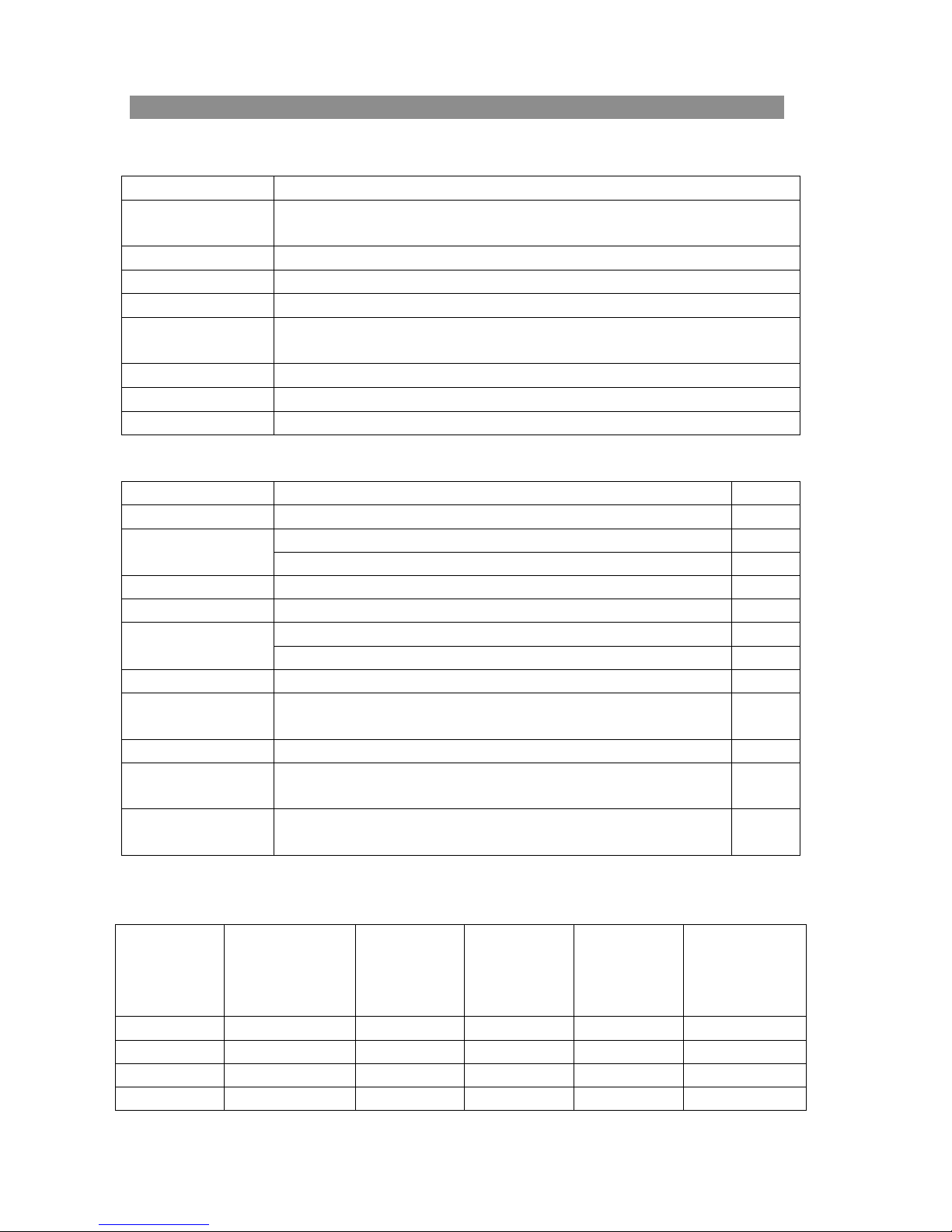
Specifications 3025
Main specifications
Optical System
Viewing Head
Eyepiece (Ocular) Extra Wide Field EW10X/22, tube30 matched
Nosepiece
Objectives Infinity Plan Achromat: 4x, 10x, 40x, 100x Oil
Focus System
Stage Double plate mechanical stage; 185 x 142mm; movement range: 75 x 55mm
Koehler Illumination Koehler illumination system, Aspheric collector, halogen lamp 6V30W
Condenser Swing out condenser N.A. 0.9
Configuration Table
Viewing Head Compensation Free Trinocular Head
Eyepiece Extra Wide Field Eyepieces: EW10x/22
Objectives
Condenser Swing out Condenser N.A. 0.9/0.25
Video Accessories
Video Mount
Polarization
Turret Phase Contrast
Condenser
Darkfield Condenser
Fluorescent
Attachment
Temperature Control
Device
Note: ●Standard ○ Optional
Objective Specifications
Objective Specifications
Objective SpecificationsObjective Specifications
Magnification
4X 0.10 25.42 0.17 Red
10X 0.25 11 0.17 Yell ow
40X 0.65 0.75 0.17 Blue
100X 1.25 0.21 0.17 Black and White
Infinit y Optical System
Compensation Free Trinocular Head, Inclined 30º; Diopter ±5
Interpupillar y distance: 48-75mm
Reversed Quintuple Nosepiece
Coaxial Coarse and Fine Focusing System
Sensitivity and Graduation of Fine Focus: 0.001mm
Infinite Plan objectives: 4x, 10x, 40x, 100x Oil
Infinite Plan Objective: 20x
C-Mount 1x
C-Mount 0.5x
Numerical Value
Aperture
Diaphragm
(N.A.)
Working
Distance
(mm)
Thickness of
Cover Slip
(mm)
Conjugate
Distance
(mm)
○
○
○
○
○
Objective Color
Coding
15

16

IMAGE PROBLEMS
Problem Cause Corrective Measure
Image tinged yellow Lamp intensity is too low Adjust the light intensity by
rotating the intensity control
dial
Image is too bright Lamp intensity is too high Adjust the light intensity by
rotating the intensity control
dial
Insufficient brightness Lamp intensity is too low Adjust the light intensity by
rotating the intensity control
dial
Aperture diaphragm closed Open to the proper setting
too far
Condenser position too low Position the condenser at
the upper limit
MECHANICAL PROBLEMS
Image will not focus with Slide upside down Turn the slide over so the
high power objectives cover glass faces up
Cover glass is to thick Use a 0.17mm cover glass
High power objective contacts Slide upside down Turn the slide over so the
slide when changed from cover glass faces up
low power objective
Cover glass is to thick Use a 0.17mm cover glass
Diopter adjustment is not set Readjust the diopter settings
properly
Lamp does not light when No electrical power Check power cord connection
switched on
Lamp bulb burnt out Replace bulb
Fuse blown out Replace fuse
Slippage of focus when using Tension adjustment is set too Increase the tension on the
the coarse focusing knob low focusing knobs
Fine focus is ineffective Tension adjustment is set too Loosen the tension on the
high focusing knobs
17

ORDERING INFORMATION
Cat. #
25097
Description
3025 Upright Microscope with Dual Observation 1 unit
Order online anytime at www.polysciences.com
Polysciences, Inc.
400 Valley Road
Warrington, PA 18976
Polysciences Europe GmbH
Handelsstrasse 3
D-69214 Eppelheim
Germany
Asia-Pacific Headquarters
Polysciences Asia Pacific, Inc.
2F-1, 207 DunHua N. Rd.
Taipei, Taiwan 10595
(800) 523-2575 / (215) 343-6484
(800) 343-3291 / (215) 343-0214 fax
info@polysciences.com
www.polysciences.com
(49) 6221-765767
(49) 6221-764620 fax
info@polysciences.de
(886) 2 8712 0600
(886) 2 8712 2677 fax
info@polysciences.tw
Our catalog lists over 3,000 unique and specialty products that are used by histology professionals, lab technicians,
pathologists, chemists and scientists worldwide. Visit www.polysciences.com to learn more about our product lines.
 Loading...