

Page 1

110-031 PSC/EN
Operator’s Manual
General Purpose Water Baths
110-031 PSC/EN 25 February 2014
1
Find Quality Products Online at: sales@GlobalTestSupply.com
www.GlobalTestSupply.com
Page 2

110-031 PSC/EN
Table of Contents
Introduction ........................................................................................... 2
General Safety Information .............................................................. 2
Safety Recommendations ................................................................ 3
Regulatory Compliance & Testing .................................................... 4
Unpacking Your Water Bath ............................................................. 4
Contents ........................................................................................... 4
LCD Display ..................................................................................... 5
Keypad ............................................................................................. 5
Installation and Startup ......................................................................... 6
General Site Requirements ............................................................... 6
Adding Liquid to the Reservoir .......................................................... 6
Electrical Power ................................................................................ 8
Controller Setup ................................................................................ 8
Power On .......................................................................................... 8
Selecting the Temperature Unit ........................................................ 8
Setting the High Limit Value .............................................................. 9
Setting the Temperature Presets ...................................................... 9
Normal Operation .................................................................................10
Keypad Controls ............................................................................... 10
Turning Your Water Bath ON ............................................................ 10
Adjusting the Set Point Temperature ................................................10
Setting and Using the Timer ............................................................. 11
Using the Temperature Presets ........................................................11
Entering a Calibration Offset ............................................................12
Resetting the Factory Default Values ............................................... 13
Loss of Power Restart ...................................................................... 13
Displaying the Firmware Version ......................................................13
Display Messages and Alarms ............................................................14
Routine Maintenance & Troubleshooting ...........................................15
Draining the Bath Reservoir ............................................................. 15
Resetting the Over Temperature / Low Liquid Level Safety .............15
Cleaning the Bath ............................................................................16
Troubleshooting Chart ......................................................................16
Technical Information ..........................................................................17
Performance Specications .............................................................17
Reservoir Fluids ...............................................................................18
Application Notes .............................................................................19
Equipment Disposal (WEEE Directive) ............................................... 20
Service and Technical Support ...........................................................21
Warranty ................................................................................................21
1
Find Quality Products Online at: sales@GlobalTestSupply.com
www.GlobalTestSupply.com
Page 3
110-031 PSC/EN
Introduction
Thank you for choosing this Water Bath. It is designed to handle a wide
range of laboratory procedures including: incubation, inactivation and agglutination as well as most pharmaceutical, serological, biomedical and
industrial procedures.
To ensure optimium temperature uniformity, your Water Bath features
an energy efcient, large-area heater and thermostatic control. Its PID
microprocessor control (Proportional Integral Derivative) system provides
proportional heat control by anticipating the approach to your set point
temperature and preventing overshoot. A redundant safety thermostat is
standard on all models.
General Safety Information
When installed, operated and maintained according to the directions in
this manual and common safety procedures, your Water Bath should
provide safe and reliable temperature control. Please ensure that all
individuals involved in the installation, operation or maintenance of this
Water Bath read this manual thoroughly prior to working with the unit.
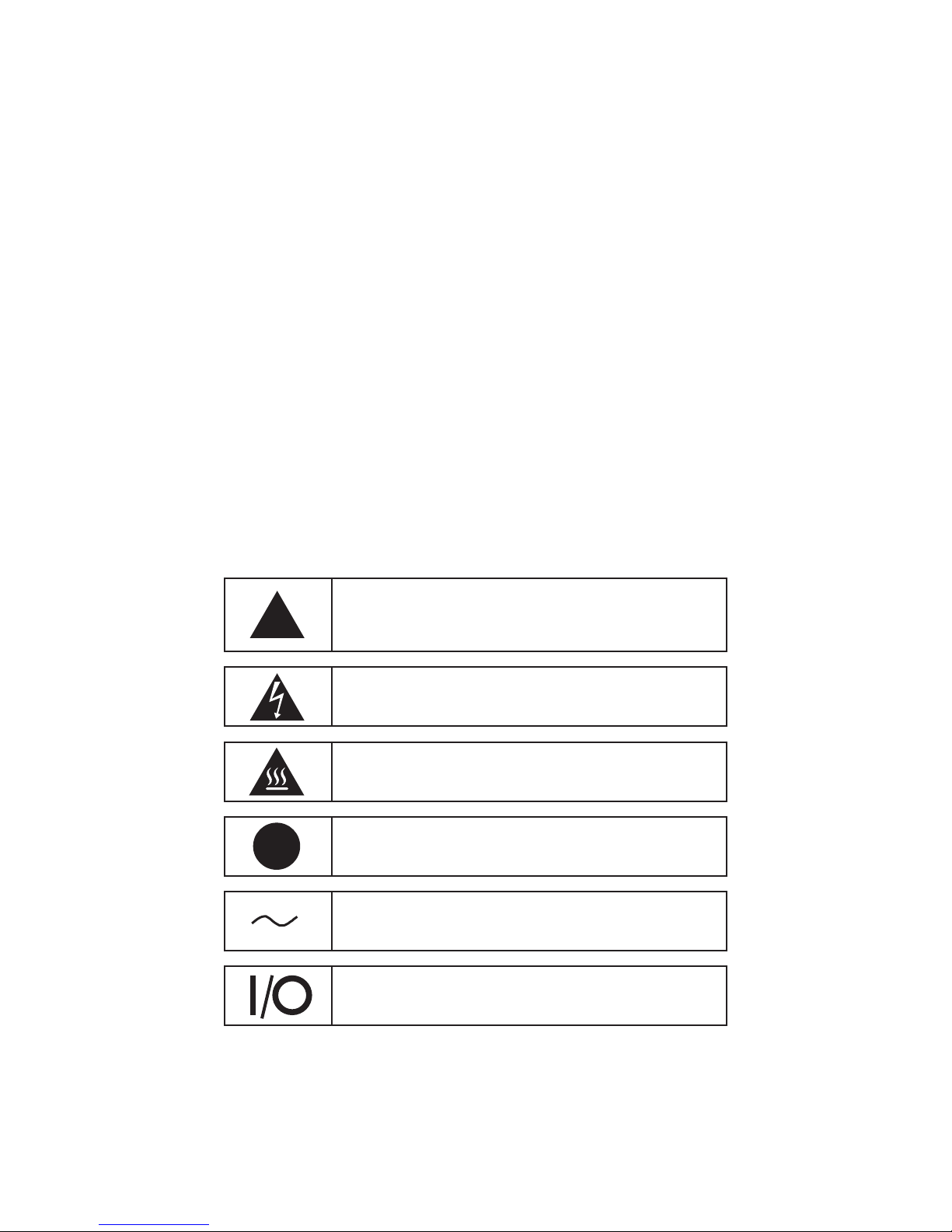
This symbol marks chapters and sections of this instruction
manual that are particularly relevant to safety. When attached
!
to the unit, this symbol draws attention to the relevant section
of the instruction manual.
!
This symbol indicates that hazardous voltages may be
present.
This symbol indicates that hot surfaces or liquids may be
present.
This symbol marks information that is particularly important.
This symbol indicates alternating current.
These symbols on the Power Switch indicate that they place
the main power supply ON/OFF.
2
Find Quality Products Online at: sales@GlobalTestSupply.com
www.GlobalTestSupply.com
Page 4
110-031 PSC/EN
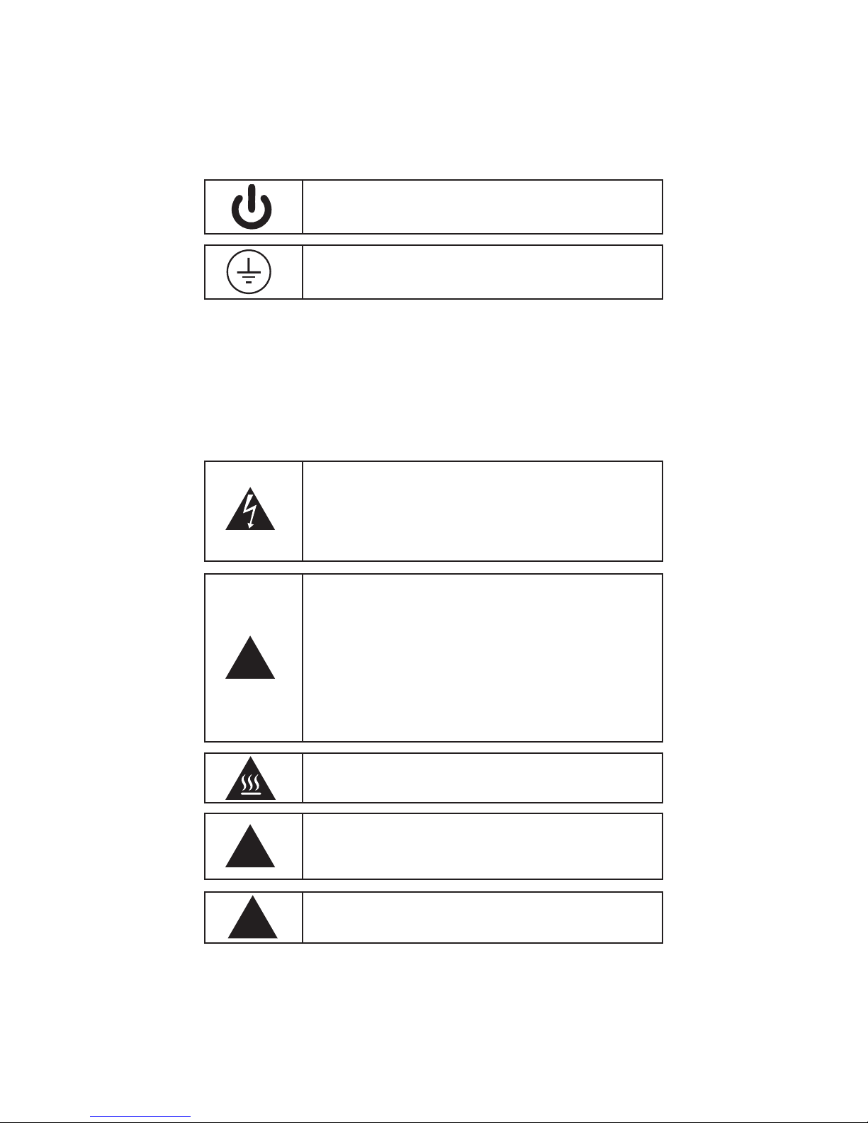
This symbol on the Power Button indicates that it places the
unit in a standby mode. IT DOES NOT fully disconnect the
unit from the power supply.
This symbol indicates a protective conductor terminal.
Read all instructions pertaining to safety, set-
up and operation. Proper operation is the user’s
responsibility.
Safety Recommendations
To prevent injury to personnel and/or damage to property, always follow
your workplace’s safety procedures when operating this equipment. You
should also comply with the following safety recommendations:
WARNING:
• Always connect the power cord on this Water Bath to a
grounded (3-prong) power outlet. Make certain that the
outlet is the same voltage and frequency as your unit.
• Never operate the Water Bath with a damaged power
cord.
• Always turn the Water Bath Off and disconnect mains
power before performing any maintenance or service.
WARNING:
• Never operate the Water Bath without bath uid in the
reservoir. Periodically check the reservoir to ensure that
the liquid depth is within acceptable levels. Always rell
the reservoir using the same bath uid type that is already
in the reservoir. Bath oil must not contain any water
contaminants and should be preheated to the actual bath
!
temperature before adding as there is an explosion hazard
at high temperatures.
• Use compatible bath uids only.
• Always drain all uid from the reservoir before moving
or lifting your Water Bath. Be sure to follow your
organization’s procedures and practices regarding the
safe lifting and relocation of heavy objects.
WARNING: Always allow the bath uid to cool to ambient
temperature before draining.
WARNING: It is the user’s responsibility to properly
decontaminate the unit in the event hazardous materials are
spilled on exterior or interior surfaces. Consult manufacturer
!
!
Find Quality Products Online at: sales@GlobalTestSupply.com
if there is any doubt regarding the compatibility of
decontamination or cleaning agents.
CAUTION: If the equipment is used in a manner not
specied by the manufacturer, the protection provided by the
equipment may be impaired.
3
www.GlobalTestSupply.com
Page 5
110-031 PSC/EN
Regulatory Compliance & Testing
This product has been tested to the requirements of CAN/CSA-C22.2
No. 61010-1, second edition, including Amendement 1, or a later
version of the same standard incorporating the same level of testing
requirements.
ETL (60 Hz units)
UL 61010-1 / CSA C22.2 No. 61010-1, 2nd Edition 07/12/04 (R
10/28/2008)
IEC 61010-2-010: 2003, CSA C22.2 No. 61010-2-010:2004/07/01 Ed:2
(R2009)
CE (50 Hz units)
Low Voltage Directive 2006/95/EC
EN 61010-1, 2nd Edition Issued March, 2001
EN 61010-2-010 2nd Edition Issued October, 2003
EMC Directive 2004/108/EC
EN 61326-1: 2006
Machinery Directive 2006/42/EC Annex I
All Units - RoHS2 2011/65/EU
Unpacking Your Water Bath
Your water bath is shipped in a special carton. Retain the carton
and all packing materials until the unit is completely assembled and
working properly. Set up and run the unit immediately to conrm proper
operation. Beyond one week, your unit may be warranty repaired, but not
replaced. If the unit is damaged or does not operate properly, contact the
transporation company, le a damage claim, then contact the company
where your unit was purchased.
WARNING: Keep unit upright when moving. Be sure to follow
!
your company’s procedures and practices regarding the safe
lifting and relocation of heavy objects.
Contents
The items included with your Water Bath are:
• Water Bath
• Gabled Reservoir Cover Assembly
• Sample Tray
• Operator’s Manual
• Quick-Start Guide
• Selection Guide
4
Find Quality Products Online at: sales@GlobalTestSupply.com
www.GlobalTestSupply.com
Page 6
110-031 PSC/EN
LCD Display
High Limit Warning
set point higher than
the High Limit value.
Lit steady when High
Limit value is being
warning condition is
Set Point Indicator
changed; lit steady
Timer Symbol
Lit when timer
is being set or
Indicator
Flashes if you
attempt to enter a
set
Heating Symbol
Lit when heater is
Fault / Warning
Lit when fault or
set point is being
active
Symbol
detected
Flashes when
during normal
operation
is in use
Over-Temperature /
Low Liquid Symbol
Lit when over-
temperature or low
liquid level fault is
detected
Loss of Power
Indicator
Lit when electrical
power is restored
after power disruption
Calibration Mode
Indicators
Lit when unit
calibration offset is
being set
Version Indicator
Lit when rmware
version ID is being
displayed on the
lower readout
Temperature Unit
Symbol
Shows
temperature unit in
use when lit
Upper Readout
Displays actual
bath temperature
Lower Readout
Displays set point
temperature
during normal
operation; displays
operational
information when
Menu button is
pressed
Temperature
Resets Indicator
Lit when preset
is being set or is
in use
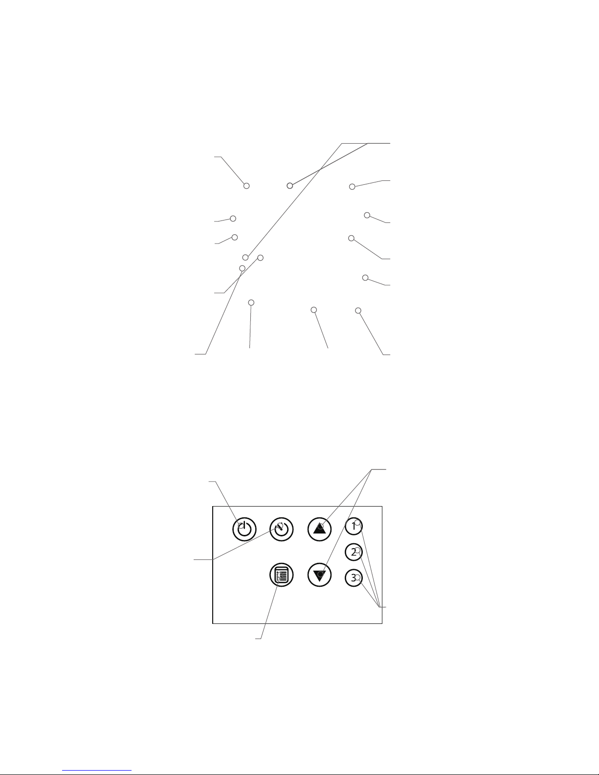
Keypad
Power Button
Turns power to
the Controller On
and Off
Timer Button
Used to start
and stop the
timer
Menu Button
Used to select and set various
operational parameters
Selection Buttons
Used to increase
or decrease
temperature
settings and
operational
parameters
Temperature
Preset Buttons
Used to select
frequently used
user-dened
set point
temperatures
5
Find Quality Products Online at: sales@GlobalTestSupply.com
www.GlobalTestSupply.com
Page 7
110-031 PSC/EN
Installation and Startup
Your Water Bath is designed to be simple to setup and install. All that is
required is a container for adding water or another suitable uid to the
bath reservoir.
General Site Requirements
Locate your Water Bath on a level surface in an area that is free from
drafts and wide ambient temperature variations, such as near heater or
air conditioning vents. Do not place it where there are corrosive fumes,
excessive moisture, or in excessively dusty areas.
Avoid voltage drops by using properly grounded power outlets wired with
14 gauge or larger diameter wire and, if possible, be close to the power
distribution panel. the use of extension cords is not recommended; this
will reduce the potential for problems caused by low line voltage.
Adding Liquid to the Bath Reservoir
WARNING: Read the safety data sheet for the bath uid
being used carefully before lling reservoir.
WARNING: See Technical Information, Reservoir Fluids
!
(page 18) for a list of compatible liquids.
WARNING: If the proper uid level is not maintained, the unit
could possible by damaged (uid level too low) or the bath
may overow (uid level too high).
CAUTION: Fumes from acidic solutions may cause corrosion
!
Fill bath so that the liquid level is approximately one inch (2.54 cm) from
top when samples are placed in the bath.
To ensure accurate reading of temperature, the uid level should not be
less than 2 inches (5.08 cm) from the bottom of the unit. Operation of the
bath without uid will not damage the heater, but will cause permanent
discoloration of the tank and will not provide accurate temperature
information.
Distilled water is preferred for temperatures from 10° to 90°C (50° to
194°F). A variety of uids can be used with the bath depending on the
application. The uid must be compatible with 300 series stainless
steel. See Technical Information, Reservoir Fluids (page 18) for a list of
compatible uids.
If using water, a few drops of polyclean Algaecide (part number 004-
300040) should be used to help prevent algae formation.
of the stainless steel reservoir. Care should be taken to
maintain a neutral pH at all times.
6
Find Quality Products Online at: sales@GlobalTestSupply.com
www.GlobalTestSupply.com
Page 8

110-031 PSC/EN
WARNING: Always drain all uid from the reservoir before
moving or lifting your Water Bath. Be sure to follow your
!
organization’s procedures and practices regarding the safe
lifting and relocation of heavy objects.
WARNING: To avoid the potential for burns, allow the Water
Bath to cool completely before cleaning or performing any
maintenance.
7
Find Quality Products Online at: sales@GlobalTestSupply.com
www.GlobalTestSupply.com
Page 9

110-031 PSC/EN
Electrical Power
WARNING: The Water Bath’s power cord must be connected
to a properly grounded electrical receptacle. Make certain
that this electrical outlet is the same voltage and frequency as
your Water Bath. The correct voltage and frequency of your
Water Bath are indicated on the identication label on the
rear of the unit.
CAUTION: The use of an extension cord is not
recommended. If one is necessary, it must be properly
!
Insert the power cord into a properly grounded
electrical outlet.
Place the Mains Switch on the rear of the unit in the
On position. The three decimal points in the upper
readout light to indicate that the Water Bath is in the
Standby mode.
grounded and capable of handling the total wattage of the
unit. The extension cord must not cause more than a 10%
drop in voltage to the unit.
Controller Setup
Power On
1. Place the Mains Switch on the rear of the unit in the On position. The
three decimal points in the upper readout light to indicate that the
Water Bath is in the Standby mode.
2. Press . The actual bath temperature is displayed on the upper
readout and the set point temperature is displayed on the lower
readout. Both values are displayed to one decimal point. If the actual
bath temperature is lower than the set point temperature, the unit will
automatically begin heating and the heating symbol will light.
Selecting the Temperature Unit
1. Press until ºC or a ºF appears on the lower readout.
2. If ºC is shown, press to change it to ºF. If ºF is shown, press to
change it to ºC.
3. Press or allow the display to timeout (~10 seconds) to accept the
displayed temperature unit.
8
Find Quality Products Online at: sales@GlobalTestSupply.com
www.GlobalTestSupply.com
Page 10

110-031 PSC/EN
Setting the High Limit Value
This menu item allows you to enter a high temperature alarm value, and
can establish a temperature above which a set point temperature cannot
be entered. If you try to increase the set point to a temperature higher
than the High Limit value, further increases will be blocked and the words
HIGH LIMIT on the LCD will ash.
1. Press until the words HIGH LIMIT appear on the LCD; the current
High Limit value will appear on the lower readout.
2. Use the and buttons to set the high limit value to the desired
temperature; this value may be set as high as 105ºC (221ºF).
3. Press or allow the display to timeout (~10 seconds) to accept the
displayed High Limit value. The words HIGH LIMIT will no longer be
lit.
Setting the Temperature Presets
1. Press until PRESET appears on the lower readout.
2. Use the and buttons to adjust the set point displayed on the
lower readout to the desired temperature.
!
3. Press until the word TIMER is displayed on the LCD; the two left
hand digits in the lower readout will begin ashing.
4. Use the and buttons to set the time duration in hours; this value
may be set anywhere from 00 to 99 hours.
5. Press again; the two right hand digits in the lower readout will
begin ashing.
6. Use the and buttons to set the time duration in minutes; this
value may be set anywhere from 00 to 59 minutes.
7. Press or allow the display to timeout (~10 seconds) to accept the
displayed Time Duration value.
8. Press and hold the Preset button ( , or ) you wish to associate
with the set point and time optional timer values you entered for ten
seconds to accept. The unit will beep to indicate the Preset has been
accepted.
NOTE: Steps 3 through 7 below are optional.
9
Find Quality Products Online at: sales@GlobalTestSupply.com
www.GlobalTestSupply.com
Page 11

110-031 PSC/EN
Normal Operation
Keypad Controls
Power Turns the Controller On and Off.
Used to select and set temperature
Menu
units, timer time duration, high limit
temperature and calibration offset. Also
used to display the rmware version ID.
Timer
Selection
Temperature
Presets
(1, 2, 3)
Used to start, pause and reset the
timer.
Used to increase/decrease temperature
set point and other operational settings/
values.
Used to select one of three user-
dened set point temperatures and
optional time duration.
Turning Your Water Bath On
1. Place the Mains Switch on the rear of the unit in the On position. The
three decimal points in the upper readout light to indicate that the
Water bath is in the Standby mode.
2. Press . The actual bath temperature is displayed on the upper
readout and the set point temperature is displayed on the lower
readout. Both values are displayed to one decimal point. If the actual
bath temperature is lower than the set point temperature, the unit will
automatically begin heating and the heating symbol will light.
Adjusting the Set Point Temperature
This is the temperature at which the uid in your bath will be maintained.
It may be set to one-tenth of a degree. The factory default set point is
+20.0ºC/+68ºF.
1. Press the or button. The word SET on the LCD will begin
ashing.
2. Use the and buttons to adjust the set point temperature to the
desired value. Press or allow the display to timeout (~10 seconds)
to accept the new value; the word SET on the LCD will be lit steady.
10
Find Quality Products Online at: sales@GlobalTestSupply.com
www.GlobalTestSupply.com
Page 12

110-031 PSC/EN
Setting and Using the Timer
1. Press until TIMER appears on the LCD; the two left hand digits in
the lower readout will begin ashing.
2. Use the and buttons to set the time duration in hours; this value
may be set anywhere from 00 to 99 hours.
3. Press again; the two right hand digits on the lower readout will
begin ashing.
4. Use the and to set the time duration in minutes; this value may
be set anywhere from 00 to 59 minutes.
5. Press or allow the display to timeout (~10 seconds) to accept the
displayed Time Duration value.
6. Press to start the timer; and the word TIMER on the LCD will
light. To pause the Timer, press a second time; press again to
restart the Timer from the point at which it was stopped. To reset the
Timer to 00:00, press and hold for two seconds.
The Timer counts down until it reaches 00:00, beeps and then begins
counting up. This is intended to inform you about how much time has
elapsed since the timer reached 00:00. To clear the Timer Value, place
the unit in Standby mode and press to return from Standby mode.
NOTE: When the Timer is operating, the lower readout
!
alternates between the time remaining (or elapsed) and the
temperature set point at 5 second intervals.
Using the Temperature Presets
Press the desired Preset button ( , or ). The word PRESET and
the number associated with that preset will light on the LCD. If the Preset
includes a Timer function, the word TIMER and will also light. The
actual bath temperature and the set point temperature / time (alternating)
will be displayed on the upper and lower readouts, respectively (set point
only if there is no timer function associated with the Preset).
NOTE: When the Preset includes a Timer function, will
light and the timer will begin counting down when the actual
!
bath temperature is within ±0.5° of the set point temperature.
The Timer can also be activated manually by pressing the
Timer button.
11
Find Quality Products Online at: sales@GlobalTestSupply.com
www.GlobalTestSupply.com
Page 13

110-031 PSC/EN
Entering a Calibration Offset
This menu item allows you to offset all bath temperature readings by -7
to +7ºC. For example, if the Calibration Offset is set to +0.5º the bath will
display temperature readings of 20ºC, 50ºC and 70ºC as 20.5ºC, 50.5ºC
and 70.5ºC, respectively.
The Calibration Offset is always set in ºC. If you have selected ºF as
the temperature unit, the Water Bath automatically converts the ºC
calibration offset value to the correct ºF value when normal operation is
resumed.
To prevent the Calibration Offset from being changed unintentionally,
the following power down/power up sequence is required to enable the
Calibration Offset function:
NOTE: If the operator tries to enter a Calibration Offset
!
1. Place the Mains Switch on the rear of the unit in the Off position.
2. Press and hold while returning the Mains Switch to the On
position.
3. When the unit enters Standby (the three decimal points in the upper
display lit), release .
4. Press .
5. Press until the words CALIBRATION OFFSET light on the LCD.
The actual bath temperature will be displayed in degrees C on
the upper readout and the current Calibration Offset value will be
displayed in degrees C on the lower readout.
6. Use the and buttons to set the Calibration Offset to the desired
value. As the Calibration Offset value is entered, the reading on the
upper display will also change to reect the new calibration offset
value.
7. Press or allow the display to timeout (~10 seconds) to accept the
displayed Calibration value. The words CALIBRATION OFFSET will
no longer be lit.
without following the proper power down/power up sequence,
the words CALIBRATION OFFSET on the LCD will ash.
The Calibration Offset function will remain enabled until the unit is turned
Off by pressing .
12
Find Quality Products Online at: sales@GlobalTestSupply.com
www.GlobalTestSupply.com
Page 14

110-031 PSC/EN
Resetting the Factory Default Values
1. Press to turn the Circulator Off.
2. Place the Mains Switch on the rear of the unit in the Off position.
3. Return the Mains Switch to the On position while pressing and
holding either the or button.
The factory default values are:
Operational Parameter Factory Default Value
Temperature Set Point 20ºC/68ºF
Temperature Scale ºC
Timer 00:00
High Limit 99.9ºC/211.8ºF
Calibration Offset 0.0ºC
Preset 1
Preset 2
Preset 3
Set Point: 37°C
Timer: 0
Set Point: 44°C
Timer: 0
Set Point: 70°C
Timer: 0
Loss of Power Restart
In the event that electrical power is lost while your Water Bath is in use,
it will begin operating automatically at the set point temperature once
power is restored. The timer will begin counting up from the point at
which power was restored. POWER FAIL will appear on the display to
alert you that there was a power disruption. To clear the message, turn
the bath Off and then back On again by pressing .
Displaying the Firmware Version
The version number for the Water Bath’s rmware is accessed by
pressing until the word VERSION appears on the LCD. The version
number will be displayed on the lower readout; this is a read-only value.
Press or allow the display to timeout (~10 seconds) to exit the Menu
function.
13
Find Quality Products Online at: sales@GlobalTestSupply.com
www.GlobalTestSupply.com
Page 15

110-031 PSC/EN
Display Messages and Alarms
Symbol and/or Word Description Comments/Corrective Action
HIGH LIMIT
(ashing)
!
CALIBRATION
OFFSET
(ashing)
POWER FAIL
SET
(ashing)
°C or °F
on lower readout.
TIMER
HIGH LIMIT
(steady)
CALIBRATION
OFFSET
(steady)
PRESET
1, 2 or 3
TIMER
Warning: The operator is attempting
to enter temperature set point that
is above the High Limit temperature
value.
Fault: The liquid in the bath has
dropped too low or the temperature
of the bath uid has exceeded the
Safety Set temperature. Power to
the heater will remain Off until the
over-temperature thermostat resets.
Warning: The operator is attempting
to enter a Calibration Offset value
without rst performing the proper
power down/power up sequence.
Informational: Indicates that there
was a loss of electrical power during
operation.
Informational: Indicates that the
temperature set point is being
changed.
Informational: Indicates that the
temperature unit is being changed.
Informational: Indicates that the
timer is being set.
Informational: Indicates that the
high limit value is being changed.
Warning: Indicates that the bath
temperature has exceeded the high
limit value for more than 5 seconds.
Informational: Indicates that the
calibration offset value is being
changed.
Informational: Indicates that the
bath is operating using the indicated
Preset set point temperature and
timer (optional) values.
Informational: Indicates that the
timer is being used.
Informational: Indicates that heat is
being applied to the bath.
Increase the High Limit temperature value or
decrease the set point temperature.
Fluid level in the reservoir has fallen below
minimum level; remove power, allow bath to
come to room temperature and add uid.
Fluid temperature is higher than one or
both Over-Temperature Safety thermostats.
Remove power and allow bath to come to room
temperature; if problem persists, consult factory.
Controller failure; consult factory.
Place Mains Switch on rear of unit in Off
position. Press and hold while returning
Mains Switch to On position. Release when
unit enters Standby mode.
Press on keypad and then press until
CALIBRATION OFFSET appears on LCD.
Press to turn the Water Bath Off and then
back On. This will clear the message.
Press
or until desired set point
temperature is displayed on lower readout.
Press or allow the display to timeout to
accept.
Press
to change ºC to ºF; press to
change ºF to ºC. Press or allow the display
to timeout to accept.
Use the
or buttons to increase/
decrease the time duration. Press or allow
the display to timeout to accept.
Press
or until desired high limit
temperature is displayed on lower readout.
Press
or allow the display to timeout to
accept.
Allow bath temperature to fall below the High
Limit Value.
Place unit in Standby mode and press to
return from Standby mode. Reset factory default
values
Press
or until desired calibration offset
is displayed on lower readout. Press
allow the display to timeout to accept.
No action required.
Press and release
and hold for two seconds to reset to 00:00.
This symbol is lit steady while the bath is
heating to the set point temperature and
ashes when the set point temperature is being
maintained.
to pause timer. Press
or
14
Find Quality Products Online at: sales@GlobalTestSupply.com
www.GlobalTestSupply.com
Page 16

110-031 PSC/EN
Symbol and/or Word Description Comments/Corrective Action
- - -
Beeping Pattern
Warning: Sensor Failure Turn the Water Bath Off. Place mains switch
in the Off position. Unplug the unit and contact
Routine Maintenance & Troubleshooting
WARNING: Hazardous voltages may be present. Disconnect
power before performing maintenance.
WARNING: Always allow the bath to cool to ambient
temperature before performing any maintenance.
Draining the Bath Reservoir
Water Baths with 10, 20 and 28 liter
reservoirs have a drain port located
on the rear of the unit. To drain uid
from the bath reservoir, place a
suitable container beneath the drain
port and remove the cap and o-ring.
Drain
WARNING: Be sure to reinstall the cap on the drain outlet
!
before relling the bath reservoir. Always verify the o-ring is
properly installed inside the cap.
Resetting the Over-Temperature/Low Liquid Level Safety
Also see Display Messages and Alarms (page 14) and the
Troubleshooting Chart (page 16).
For optimal protection, your Water Bath incorporates redundant overtemperature safeties. These over-temperature/low liquid level safeties
automatically remove power from the heater in the event that the bath
temperature exceeds their factory set temperature settings.
While these safeties are designed to automatically reset when the
bath returns to a temperature below the factory set safety settings,
we recommend that you take the following actions when the overtemperature/low liquid level warning is activated.
1. Press to place the Water Bath in the Standby mode.
2. Allow the liquid in the Water Bath to cool to ambient temperature.
3. If the liquid level in the bath is too low, add liquid as required.
4. Press .
If the problem persists, contact
15
Find Quality Products Online at: sales@GlobalTestSupply.com
www.GlobalTestSupply.com
Page 17

110-031 PSC/EN
Cleaning the Bath
Thoroughly clean the bath before each use. Use only mild soap and
water when cleaning. Do not use steel wool as damage to the unit may
result. Non-steel scouring pads are acceptable.
The entire unit is housed in a tough, well-insulated powder-coated steel
casing that is corrosion and chemical resistant.
Troubleshooting Chart
Problem Cause Corrective Action
Check that power cord is
No display
No heating
No power to unit
Mains Switch in Off
position
Set point lower than bath
temperature
Bath temperature above
High Limit temperature
Liquid level in bath is
too low
Improper line voltage
plugged into an operating
electrical outlet
Check that Mains Switch on
the rear of the unit is in the On
position
Check set point temperature;
increase as required.
Verify that High Limit
temperature is higher than
current set point temperature;
adjust as required (see page 8).
Check that liquid level is at
least 2 inches (5.08 cm) above
bottom of tank; add uid as
required.
Check that line voltage meets
specications.
Allow sufcient time for bath
Insufcient
heating
Inaccurate bath
temperature
Find Quality Products Online at: sales@GlobalTestSupply.com
Recent change in set
point or heat load
Bath cover not in place
Incorrect calibration
temperature to stabilize when
changes in heat load or set
point are made.
Check that bath cover is in
place.
Adjust Calibration Offset as
required (see page 10).
www.GlobalTestSupply.com
16
Page 18

110-031 PSC/EN
Technical Information
Performance Specications
Working Temperature:
Ambient +5ºC to 100ºC (ambient +10º to 212ºF)
60ºC (140ºF) without cover
Temperature Uniformity:
Temperature Stability:
Reservoir
Size
2 liter
5 liter
10 liter
20 liter
28 liter
Environmental Conditions Indoor use only
Maximum Altitude:
Operating Ambient:
Relative Humidity:
Installation Category:
Pollution Degree:
Reservoir Dimensions
(L x W x D)
3.9 x 4.3 x 6”
9.9 x 10.9 x 15.2 cm
5 x 10.8 x 6”
12.7 x 27.4 x 15.2 cm
10.6 x 11.6 x 6”
26.9 x 29.5 x 15.2 cm
9.5 x 17.5 x 5”
24.1 x 44.5 x 15.2 cm
9.5 x 17 x 8”
24.1 x 43.2 x 20.3 cm
±0.2°C @ 37°C (±0.4°F @ 98.6°F)
±0.1°C (±0.2°F)
Heater
Wattage
120
360
1000
1400
1400
Electrical Requirements
120 V, 60 Hz 240 V, 50 Hz
WB02**1*
1.1 A
WB05**1*
3.3 A
WB10**1*
8.6 A
WB20**1*
12.0 A
WB28**1*
12.0 A
2000 meter
5° to 40°C (41° to 104°F)
80%, non-condensing
II
2
WB02**2*
0.5 A
WB05**2*
1.6 A
WB10**2*
4.5 A
WB20**2*
6.0 A
WB28**2*
6.0 A
17
Find Quality Products Online at: sales@GlobalTestSupply.com
www.GlobalTestSupply.com
Page 19

110-031 PSC/EN
Reservoir Fluids
WARNING: Do not operate unit with any potentially
!
ammable materials, as a re hazard may result.
Specific Heat
Fluid Description
distilled water 50°C 1.00 4.18 10° to 90°C 2° to 100°C
polyclear MIX 30 50°C 1.00 4.18 15° to 90°C 2° to 100°C
polycool HC-50 -30°C 0.62 2.59 -50° to 100°C -62° to 118°C
polycool EG-25 (50/50
mix with distilled H
polycool EG-25 (30/70
mix with distilled H
polycool PG-20 (50/50
mix with distilled H
polycool PG-20 (30/70
mix with distilled H
polycool MIX-25 (50/50
mix with distilled H20)
polycool MIX-25 (30/70
mix with distilled H20)
O)
2
O)
2
0)
2
0)
2
@ Fluid
Temperature
-20°C 0.78 3.26 -25° to 100°C -30° to 115°C
0°C 0.89 3.72 0° to 95°C -15° to 107°C
-10°C 0.83 3.47 -20° to 100°C -30° to 115°C
5°C 0.92 3.85 5° to 90°C -10° to 107°C
-20°C 0.78 3.26 -25° to 100°C -30° to 115°C
0°C 0.89 3.72 0° to 95°C -15° to 107°C
BTU/lb
°F
KJ/Kg °C
Normal
Temperature
Range
Extreme
Temperature
Range
WARNING: DO NOT USE THE FOLLOWING
LIQUIDS:
• Automotive antifreeze with additives**
• Hard tap water**
• Deionized water with a specific resistance >1 meg
ohm
• Any flammable fluids
• Concentrations of acids or bases
• Solutions with halides: chlorides, fluorides,
!
bromides, iodides or sulfur
• Bleach (Sodium Hypochlorite)
• Solutions with chromates or chroium salts
• Glycerine
• Syltherm fluids
** At temperatures above 40°C, additives or mineral
deposits can adhere to the heater. If deposits are allowed
to build up, the heater may overheat and fail. Higher
temperatures and higher concentrations of additives will
hasten deposit build up.
18
Find Quality Products Online at: sales@GlobalTestSupply.com
www.GlobalTestSupply.com
Page 20

110-031 PSC/EN
CAUTION: Fumes from acidic solutions may cause corrosion
!
Stay within the uid’s normal range for best temperature stability and low
vaporization. At uid’s high temperature extreme:
• A fume hood may be required to prevent the buildup of vapors inside
the room.
• Fluid loss from vapor will have to be frequently replenished.
• Caution must be taken to stay well below the uid’s ashpoint.
of the stainless steel reservoir. Care should be taken to
maintain a neutral pH at all times.
Application Notes
For optimum results, maintain uid level throughout the operating period,
adding uid as needed. Attempt to rell uid at same temperature as
bath.
Use the bath lid and/or hollow plastic oating balls (part number 060301)
to help prevent heat and vapor loss.
This unit is designed for indoor use only with an allowable ambient
temperature between +5°C to 40°C (41° to 104°F) and relative humidity
not greater than 80%.
19
Find Quality Products Online at: sales@GlobalTestSupply.com
www.GlobalTestSupply.com
Page 21

110-031 PSC/EN
Equipment Disposal (WEEE Directive)
This equipment is marked with the crossed out wheeled bin
symbol to indicate it is covered by the Waste Electrical and
Electronic Equipment (WEEE) Directive and is not to be disposed
of as unsorted municipal waste. Any products marked with
this symbol must be collected separately, according to the
regulatory guidelines in your area.
It is your responsibility to correctly dispose of this equipment
at lifecycle-end by handing it over to an authorized facility for
separate collection and recycling. It is also your responsibility to
decontaminate the equipment in case of biological, chemical and/
or radiological contamination, so as to protect the persons involved
in the disposal and recycling or the equipment from health hazards.
By doing so, you will help to conserve natural and environmental
resources and you will ensure that your equipment is recycled in a
manner that protects human health.
Requirements for waste collection, reuse, recycling and recovery
programs vary by regulatory authority at your location. Contact
your local responsible body (e.g., your laboratory manager) or
authorized representative for information regarding applicable
disposal regulations.
20
Find Quality Products Online at: sales@GlobalTestSupply.com
www.GlobalTestSupply.com
Page 22

110-031 PSC/EN
Service and Technical Support
If you have followed the troubleshooting steps outlined previously
and your Circulator still fails to operate properly, contact the supplier
from whom the unit was purchased. Have the following information
available for the customer service person:
• Model, Serial Number and Voltage (from back panel label)
• Date of purchase and purchase order number
• Supplier’s order number or invoice number
• A summary of the problem.
Warranty
The manufacturer agrees to correct for the original user of the product, either by repair
(using new or refurbished parts), or at the manufacturer’s election, by replacement
(with a new or refurbished product), any defects in material or workmanship which
develop during the warranty period. The standard warranty is twenty-four (24) months
after delivery of the product. In the event of replacement, the replacement unit will
be warranted for the remainder of the original warranty period or ninety (90) days,
whichever is longer. For purposes of this limited warranty, “refurbished” means a
product or part that has been returned to its original specifications. In the event of a
defect, these are your exclusive remedies.
If the product should require service, contact the manufacturer’s/supplier’s office for
instructions. When return of the product is necessary, a return authorization number is
assigned and the product should be shipped, transportation charges pre-paid, in either
its original packaging or packaging affording an equal degree of protection to the
indicated service center. To insure prompt handling, the return authorization number
must be placed on the outside of the package. A detailed explanation of the defect
should be enclosed with the item.
The warranty shall not apply if the defect or malfunction was caused by accident,
neglect, unreasonable use, improper service, acts of God, modification by any part
other than PolyScience or other causes not arising out of defects in material or
workmanship.
EXCLUSION OF IMPLIED WARRANTIES. THERE ARE NO WARRANTIES,
EXPRESSED OR IMPLIED, INCLUDING, BUT NOT LIMITED TO, THOSE OF
MERCHANTABILITY OR FITNESS FOR A PARTICULAR PURPOSE WHICH EXTEND
BEYOND THE DESCRIPTION AND PERIOD AS STATED IN THE OPERATOR’S
MANUAL INCLUDED WITH EACH PRODUCT.
LIMITATION ON DAMAGES. THE MANUFACTURER’S SOLE OBLIGATION
UNDER THE WARRANTY IS LIMITED TO THE REPAIR OR REPLACEMENT OF
A DEFECTIVE PRODUCT AND POLYSCIENCE SHALL NOT, IN ANY EVENT, BE
LIABLE FOR ANY INCIDENTAL OR CONSEQUENTIAL DAMAGES OF ANY KIND
RESULTING FROM USE OR POSSESSION OF THIS PRODUCT.
Some states do not allow: (A) limitations on how long an implied warranty lasts; or
(B) the exclusion or limitation of incidental or consequential damages, so the above
limitations or exclusions may not apply to you. This warranty gives you specific legal
rights and you may have other rights that vary from state to state.
21
Find Quality Products Online at: sales@GlobalTestSupply.com
www.GlobalTestSupply.com
 Loading...