

Page 1
Operators Manual
Standard Controller Models
Pages 1 - 22
Manuel de l’utilisateur
Modèles du Contrôleur Standard
Pages 21 - 37
Bedienungsanleitung
Geräte mit Standardregelung
Seiten 38 - 54
110-227 1/8/08
Page 2
EC Declaration of Conformity
The Products herewith complies with the requirements, as stated below, in accordance to the EC Low Voltage
Directive 73/23/EEC and EC Electromagnetic Compatibility Directive 89/336/EEC, and carries the marking
accordingly.
We herewith declare:
That the following equipment complies with the essential requirements in respect to safety and health, in
accordance to the EC Directives based on its design and type, as brought into circulation by us. In case of
alteration of the equipment, not agreed upon by us, this will lose its validity.
Product Description: Refrigerated/Heated Circulators
Applicable Directives
and Harmonized Standards:
Testing Bodies:
PolyScience
Division of Preston Industries, Inc.
6600 West Touhy Avenue
P.O. Box 48312
Niles, Illinois 60714, USA
13R, 712, 7306, 7312, 812, 8006, 8012, 8002, 8112, 8102, 8106, 8202,
8212, 8206, 8306, 9006, 9012, 9002, 912, 9112, 9102, 9106, 9502, 9512,
9506, 9602, 9612, 9606, 9702, 9712, 9706;
18203, 18214, 18211, 18210, 18201, 18206, 18205, 18208, 18212, 18207,
18225, 18226, 18202;
13270-879, 13270-880, 1112A, 1122S, 1127P, 1146D, 1140S, 1147P,
1162A, 1166D, 1160S, 1167P, 1156D, 1150S, 1157P, 1196D, 1190S,
1197P, 1186D, 1180S, 1187P, 1136D, 1130S, 1137P, 1136-1D, 1130-1S,
1137-1P, 1136-2D, 1130-2S, 1137-2P;
12110-00, 12110-05, 12112-01, 12112-06, 12112-11, 12112-16, 1211212, 12112-26, 12100-10, 12100-15, 12100-20, 12100-25, 12108-00,
12108-05, 12108-20, 12108-25, 12108-10, 12108-15, 12108-30, 1210835, 12102-10, 12102-15, 12102-00, 12102-05, 12103-20, 12103-25,
12105-70, 12105-75, 12101-41, 12101-46, 12101-31, 12101-36, 1210151, 12101-56, 12111-11, 12111-16, 12111-01, 12111-06, 12111-21,
12111-26, 12107-00, 12107-05, 12107-20, 12107-25, 12107-10, 1210715, 12107-30, 12107-35, 12107-50, 12107-55, 12107-40, 12107-45,
12107-60, 12107-65, 98928-30, 98928-35.
Low Voltage Directive 73/23/EEC & Electromagnetic Compatibility
89/336/EEC and relevant transpositions into national law of the
member states, including, but not limited to the following
Harmonized Standards:
EN/IEC 61010-1: 2001
EN/IEC 61010-2
EN 61326: 1997 +A1: 1998 + A2:2001
CISPR 11/EN 55011 Class A, Group I
CSA International (Certification & Testing Division)
Ultra Tech Inc. ( EMC approval)
Signature on Behalf of
Manufacturer or Authorized
Representative:
Date of Validity:
Title of Signatory:
110-254 Rev. E 10/05
Brian Klotz
October 18, 2005
Engineering Manager
Page 3
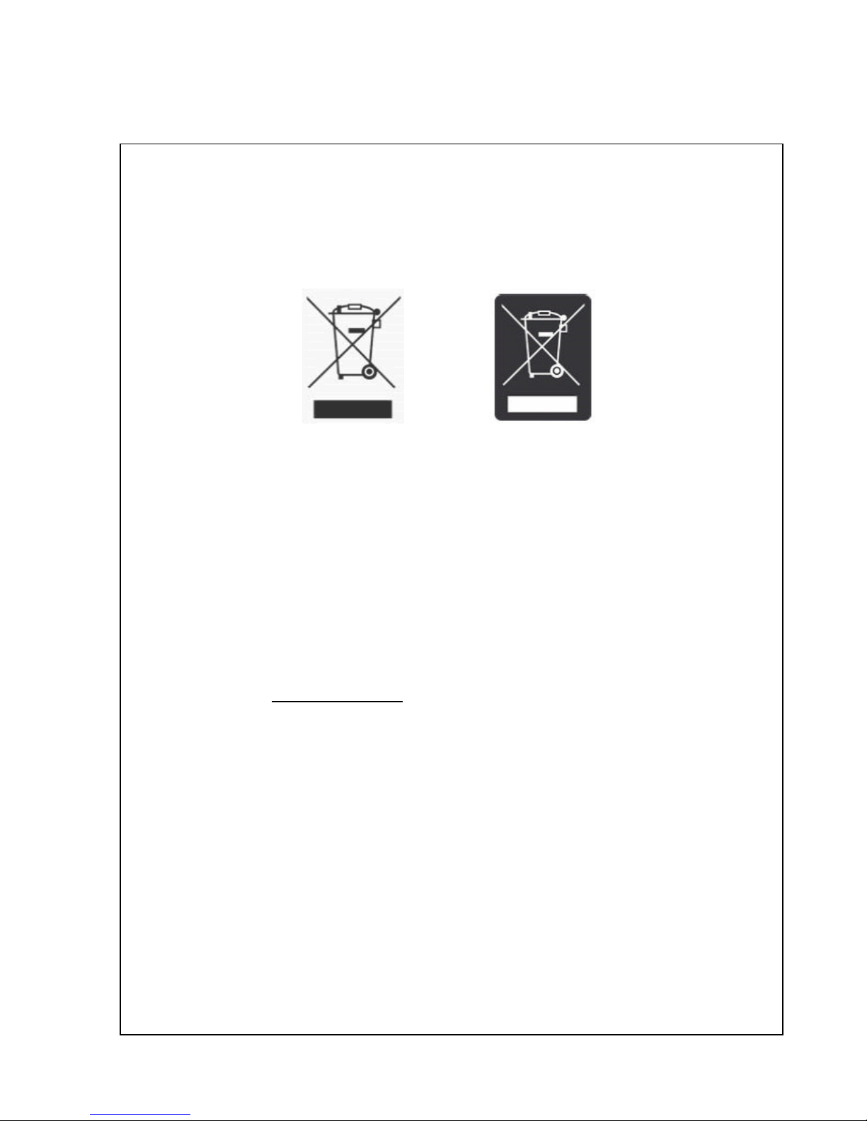
WEEE Directive
A label with a crossed-out wheeled bin symbol and a rectangular bar indicates that the product
is covered by the Waste Electrical and Electronic Equipment (WEEE) Directive and is not to
be disposed of as unsorted municipal waste.
Any products marked with this symbol must be collected separately, according to the
regulatory guidelines in your area.
The objectives of this program are to preserve, protect and improve the quality of the
environment, protect human health, and utilize natural resources prudently and rationally.
Specific treatment of WEEE is indispensable in order to avoid the dispersion of pollutants into
the recycled material or waste stream. Such treatment is the most effective means of protecting
the customer’s environment.
Requirements for waste collection, reuse, recycling, and recovery programs vary by regulatory
authority at your location.
Contact your local responsible body (e.g., your laboratory manager) or authorized
representative for information regarding applicable disposal regulations.
Contact PolyScience at the web site listed below for information.
Web address: www.polyscience.com
Customer Care: 1-800-229-7569 (inside the USA)
(+1) 847-647-0611 (outside the USA)
Fax 1-847-647-1155
or
Page 4
13R, 712, 7306, 7312, 812, 8006, 8012, 8002, 8112, 8102, 8106, 8202, 8212, 8206, 8306, 9006, 9012, 9002,
912, 9112, 9102, 9106, 9502, 9512, 9506, 9602, 9612, 9606, 9702, 9712, 9706;
18203, 18214, 18211, 18210, 18201, 18206, 18205, 18208, 18212, 18207, 18225, 18226, 18202;
13270-879, 13270-880, 1112A, 1122S, 1127P, 1146D, 1140S, 1147P, 1162A, 1166D, 1160S, 1167P, 1156D,
1150S, 1157P, 1196D, 1190S, 1197P, 1186D, 1180S, 1187P, 1136D, 1130S, 1137P, 1136-1D, 1130-1S,
1137-1P, 1136-2D, 1130-2S, 1137-2P;
12110-00, 12110-05, 12112-01, 12112-06, 12112-11, 12112-16, 12112-12, 12112-26, 12100-10, 12100-15,
12100-20, 12100-25, 12108-00, 12108-05, 12108-20, 12108-25, 12108-10, 12108-15, 12108-30, 12108-35,
12102-10, 12102-15, 12102-00, 12102-05, 12103-20, 12103-25, 12105-70, 12105-75, 12101-41, 12101-46,
12101-31, 12101-36, 12101-51, 12101-56, 12111-11, 12111-16, 12111-01, 12111-06, 12111-21, 12111-26,
12107-00, 12107-05, 12107-20, 12107-25, 12107-10, 12107-15, 12107-30, 12107-35, 12107-50, 12107-55,
12107-40, 12107-45, 12107-60, 12107-65, 98928-30, 98928-35
100-151
Page 5

712, 7306, 7312, 812, 8006, 8012, 8002, 8112, 8102, 8106, 8202, 8212, 8206,
8306, 9006, 9012, 9002, 912, 9112, 9102, 9106, 9502, 9512, 9506, 9602, 9612,
9606, 9702, 9712, 9706;
18203, 18214, 18211, 18210, 18201, 18206, 18205, 18208, 18212, 18207,
18225, 18226, 18202;
13270-879, 13270-880, 1112A, 1122S, 1127P, 1146D, 1140S, 1147P, 1162A,
1166D, 1160S, 1167P, 1156D, 1150S, 1157P, 1196D, 1190S, 1197P, 1186D,
1180S, 1187P, 1136D, 1130S, 1137P, 1136-1D, 1130-1S, 1137-1P, 1136-2D,
1130-2S, 1137-2P;
12110-00, 12110-05, 12112-01, 12112-06, 12112-11, 12112-16, 12112-12,
12112-26, 12100-10, 12100-15, 12100-20, 12100-25, 12108-00, 12108-05,
12108-20, 12108-25, 12108-10, 12108-15, 12108-30, 12108-35, 12102-10,
12102-15, 12102-00, 12102-05, 12103-20, 12103-25, 12105-70, 12105-75,
12101-41, 12101-46, 12101-31, 12101-36, 12101-51, 12101-56, 12111-11,
12111-16, 12111-01, 12111-06, 12111-21, 12111-26, 12107-00, 12107-05,
12107-20, 12107-25, 12107-10, 12107-15, 12107-30, 12107-35, 12107-50,
12107-55, 12107-40, 12107-45, 12107-60, 12107-65, 98928-30, 98928-35
100-150
Page 6
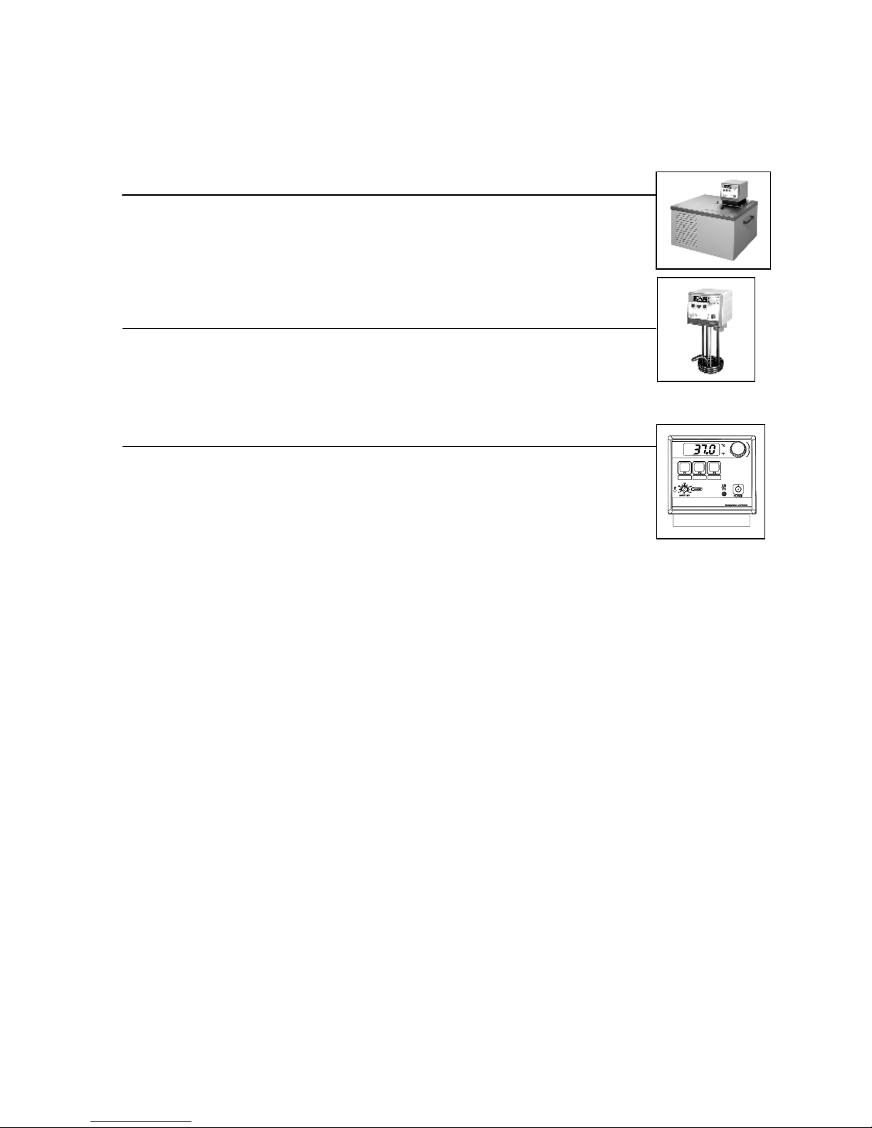
Table of Contents
Section 1 – General Information
1.1 Warranty
1.2 Unpacking
Section 2 – Circulating Bath
2.1 Contents
2.2 General Description
2.3 Circulator Pump
2.4 Pump Inlet and Outlet Connections
2.5 Closed Loop Circulation
2.6 Filling the Reservoir
2.7 Reservoir Purge
Section 3 – Immersion Circulator
3.1 Contents
3.2 General Description
3.3 Circulator Pump
3.4 Set-Up
3.5 Connections to External Apparatus
3.6 Attainable Temperatures
Section 4 – Standard Controller Information
4.1 Front and Rear Panels
4.2 Heater/Pump Assembly
4.3 Specifications
Section 5 – Operation
5.1 Circulator Location
5.2 Reservoir Liquid Level
5.3 Power
5.4 Setting the Safety Set Set Point
5.5 Selecting Temperature Units
5.6 Setting the Software High Limit
5.7 Setting the Set point Temperature
5.8 User-Defined Preset Temperatures
5.9 Local Lockout Feature
5.10 Stick-on Strips for Preset Buttons
5.11 Auto-Refrigeration Operation
5.12 Controller Display Messages
Section 6 – Calibration and Maintenance
6.1. Calibration
6.2 Heater
6.3 Pump Motor
6.4 Cleaning
6.5 Maintaining Clear Bath Water
6.6 Condenser, Air Vents, and Reusable Filter (Refrigerating/Heating Circulators only)
Section 7 – Troubleshooting
7.1 Unit Will Not Operate (No Heat, Cooling, or Pumping)
7.2 No Pumping
7.3 Slow or Insufficient Pumping
7.4 No Heating
7.5 Insufficient Heating
7.6 No Cooling or Insufficient Cooling
7.7 Triac Failure
Section 8 – Reservoir Fluids
Section 9 – Service and Technical Support
Section 10 – Replacement Parts
Page 7
Section 1 - General Information
1.1 Warranty
Thank you for purchasing this circulator. We are confident it will serve you for a long time. Our
warranty to you is as follows:
The manufacturer agrees to correct for the original user of this product, either by repair, or at the
manufacturer's election, by replacement, any defect that develops after delivery of this product
within the period as stated on the warranty card. In the event of replacement, the replacement unit
will be warranted for 90 days or warranted for the remainder of the original unit’s parts or labor
warranty period, whichever is longer.
If this product requires service, contact the manufacturer/supplier's office for instructions. When
return of the product is necessary, a return authorization number will be assigned and the product
should be shipped, (transportation charges pre-paid), to the indicated service center. To insure
prompt handling, the return authorization number should be placed on the outside of the package
and a detailed explanation of the defect enclosed with the item.
This warranty shall not apply if the defect or malfunction was caused by accident, neglect,
unreasonable use, improper service, or other causes not arising out of defects in material or
workmanship. There are no warranties, expressed or implied, including, but not limited to, those of
merchantability or fitness for a particular purpose which extends beyond the description and period
set forth herein.
The manufacturer's sole obligation under this warranty is limited to the repair or replacement of a
defective product and shall not, in any event, be liable for any incidental or consequential damages
of any kind resulting from use or possession of this product. Some states do not allow: (A)
limitations on how long an implied warranty lasts; or (B) the exclusion or limitation of incidental or
consequential damages, so the above limitations or exclusions may not apply to you. This warranty
gives you specific legal rights. You may have other rights that vary from state to state.
1.2 Unpacking
Your circulator is shipped in a special carton. Retain the carton and all packing materials until the
unit is completely assembled and working properly. Set up and run the unit immediately to confirm
proper operation. Beyond one week, your unit may be warranty repaired, but not replaced. If the
unit is damaged or does not operate properly, contact the transportation company, file a damage
claim and contact the company where your unit was purchased immediately.
Remove any loose packing material that may have fallen into the reservoir during shipping. Before
powering up, check that nothing remains around the heater or circulator pump.
The instructions in this manual pertain to both circulating baths as well as the immersion circulator.
Read the section pertaining to the special instructions for your model, then review the instructions for
all models of circulators.
This symbol marks chapters and sections of this instruction manual which are particularly relevant to safety.
This symbol indicates that hazardous voltages may be present.
Read all instructions pertaining to safety, set-up, and operation.
Proper operation is the users’ responsibility.
Page 8

Section 2 - Circulating Bath
2.1 Contents
— Circulating Bath
— Operators Manual
— Warranty Card
— Stick-on Strips for Preset Buttons (Qty 2)
— IEC Power Cord
— Tube Fitting Package Containing:
Description Quantity Part Number
— 3/16 inch Barbed Tube Fittings 2 300-049
— 1/4 inch Barbed Tube Fittings 2 300-048
— 3/8 inch Barbed Tube Fittings 2 300-047
— Hose, Bypass, Buna N (-40 to 60°C) 1 590-068
— 1/4 inch NPT – M16, Male Adapting Fittings* 2 775-290
*Included with 50Hz Models only
2.2 General Description
Refrigerating/Heating and Heat Only Circulating Baths with the Standard Controller are designed for
use as stand-alone baths or to provide precise temperature control of fluids for closed loop
circulation to external equipment.
All Circulating Bath models feature a reservoir which may be used for immersing samples while the
unit is connected to an external device. Circulating bath models are equipped with either 6, 13, or 28
liter reservoirs. All wetted parts are corrosion resistant 300 series stainless steel.
Refrigeration is normally required for operation at temperatures below 40°C. However, refrigeration
should not be used when the fluid temperature is above 55°C. Refrigeration should not be turned on
when the ambient air temperature is above 32°C.
Model Type Temperature Reservoir Amps @ Amps @
Range Capacity 120v 60Hz 240v 50Hz
Refrigerating/Heating -20° to 150°C 6L 12A 9.9A
Refrigerating/Heating -30° to 150°C 13L 13A 9.8A
Refrigerating/Heating -25° to 100°C 28L 13A 9.8A
Refrigerating/Heating -40° to 150°C 13L 14A 9.9A
Heat Only Ambient +5° to 150°C 6L 11A 9.8A
Heat Only Ambient +5° to 150°C 13L 11A 9.8A
Heat Only Ambient +5° to 150°C 28L 11A 9.8A
Environmental Conditions:
● Indoor Use Only ● Over Voltage: Category ll
● Maximum Altitude: 2000 meters ● Operating Ambient: 5° to 30°C
● Relative Humidity: 80% for temperatures to 30°C ● Pollution Degree: 2
● Class 1: Residential, Commercial, Light Industrial ● Class 2: Heavy Industrial
Warning: These units are equipped with over-temperature protection (Safety Set). A low-liquid
level or failure to set the Safety Set and properly immerse the heater may result in heater burnout
and triac failure. While operating, do not allow the heater to contact any potentially flammable
materials, such as plastic trays or the sides of plastic tanks, as a fire hazard may result.
Page 9

2.3 Circulator Pump
The two-speed simplex (pressure) pump may be used for tempering of samples
in the reservoir or for circulation in closed loops. It is not designed for pumping
from the circulator's reservoir into and out of a second open reservoir.
The HIGH or LOW Speed Selection Switch on the rear of the Controller is used to
select pump speed. LOW is adequate for most applications and provides quieter
pumping. HIGH is recommended where temperature varies frequently and there
is a need for fast recovery or when pumping to multiple external units.
Speed Maximum Pump Outlet Ratings
Selection Line Frequency = 50/60Hz
HIGH 15 LPM / 2.6 PSI
LOW 9 LPM / 1.5 PSI
The data in the table above are based on the following criteria:
1. Maximum pump outlet flow rate is measured in liters per minute (LPM) with no restriction on the pump outlet.
2. Maximum pump outlet pressure is measured in pounds per square inch (PSI) at no flow.
3. Water was used as the circulation fluid. Water has a viscosity of one centistoke. High viscosity or lowdensity fluids will change these figures.
2.4 Pump Inlet and Outlet Connections
The pump inlet and outlet ports are female ¼ inch NPT connections that
permit use of barbed tubing adapters or hard plumbing fittings. ½ inch
(13mm) ID tubing may also be slid over these connections and held in place
with a hose clamp. If the pump inlet and outlet are not used for external
circulation, they should be connected using the Buna N Bypass Hose
provided with the unit in order to optimize fluid mixing within the reservoir.
The nylon barbed tubing adapter fittings supplied with the unit are intended
for applications from -40°C to 93°C. For applications above 93°C, brass, stainless steel, or Teflon®
fittings are recommended. ¼ inch NPT to M16 stainless steel male adapter fittings are provided with
all 50Hz models.
It is the user’s responsibility to ensure that the tubing and fittings connected to the Circulator are
compatible with the bath fluid and temperature range being used.
NOTE: The use of quick-connect fittings is not recommended as they typically restrict flow rate.
2.5 Closed Loop Circulation
Connect the pump inlet and outlet to the external apparatus. To maintain adequate flow, avoid
restrictions in the tubing. When connecting the Circulator to more than two closed loops, the use of a
manifold made of "Y" adapters to divide the fluid into multiple banks is recommended. After setting
up multiple closed loops, check for adequate flow at the return manifold of each loop and check that
the bath fluid is at an adequate level. A booster pump may be added to closed loops without
damaging the Circulator’s bath pump.
The temperature control stability of a closed loop system is better at the external apparatus than in
the Circulator reservoir (provided the control point of the apparatus represents a constant load and is
well insulated). For example, if you circulate fluid through a viscometer at 50°C, the temperature
variation observed in the Circulator reservoir may be ±0.2°C while the temperature variation in the
viscometer may be only ±0.1°C.
Although temperature stability is generally better at the external apparatus control point, depending
on the length of tubing used and the efficiency of the insulation, the actual temperature reading at
the external apparatus may be slightly different than the temperature reading at the Circulator
reservoir.
Page 10

2.6 Filling the Reservoir
The maximum fill level for the Circulating bath is one inch
(25mm) below the top of the reservoir. A liquid level that fully
covers the heater coil, pump, over-temperature sensor, and at
least one inch (25mm) of the temperature sensor must be
maintained. For optimum cooling efficiency, the bath fluid level in
Refrigerating/Heating Circulators should be kept above the
cooling coils at all times.
Upon start-up, it may be necessary to add fluid to compensate
for the fluid required for external circulation. If the proper fluid
level is not maintained, the heater coil may become exposed and possibly damaged.
2.7 Reservoir Purge
When operating at low temperatures, atmospheric moisture tends to migrate into the reservoir and
condense. The 1/8 inch OD Reservoir Purge tube allows you to inject inert gas into the Circulating
bath to prevent the build-up of condensation.
Section 3- Immersion Circulator
3.1 Contents
— Immersion Circulator
— Operators Manual
— Warranty Card
— IEC Power Cord
Temperature
Sensor
Minimum
fill level
3.2 General Description
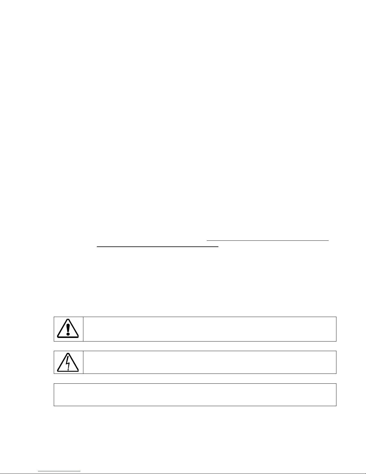
Immersion Circulators with Standard Controller are designed for use in user-supplied reservoirs.
These units can be used with many sizes and shapes of reservoirs, making them extremely versatile
and useful for a wide variety of applications.
Model Type
Heat Only
Immersion Circulator
3.3 Circulator Pump
The HIGH or LOW speed selection switch on the rear panel of the Controller is used to select pump
speed. LOW is adequate for most applications and provides quieter pumping. HIGH is
recommended where temperature varies frequently and there is a need for fast recovery or when
pumping to multiple external units.
Speed Maximum Pump Outlet Ratings
Selection Line Frequency = 50/60Hz
HIGH 15 LPM / 2.6 PSI
LOW 9 LPM / 1.5 PSI
The data in the table above are based on the following criteria:
1. Maximum pump outlet flow rate is measured in liters per minute (LPM) with no restriction on the pump outlet.
2. Maximum pump outlet pressure is measured in pounds per square inch (PSI) at no flow.
3. Water was used as the circulation fluid. Water has a viscosity of one centistoke. High viscosity or low-density
fluids will change these figures.
Temperature
Range
Ambient+5°C to 150°C* N/A 11A 7.5A
Reservoir
Capacity
Amps @
120V, 60Hz
Amps @
240V, 50Hz
Warning: These units are equipped with over-temperature protection (Safety Set). A low-liquid
level or failure to set the Safety Set and properly immerse the heater may result in heater
burnout and triac failure. While operating, do not allow the heater to contact any potentially
flammable materials, such as plastic racks or sides of plastic tanks, as a fire hazard may result.
Page 11

3.4 Set-Up
The Immersion Circulator may be clamped directly to the side of a
reservoir (user supplied) or to a support rod adjacent to the
reservoir. To produce the best fluid circulation, the rotating pump
outlet nozzle should be pointed along one side of the reservoir
wall.
The liquid in the reservoir should be maintained at a depth
sufficient to fully immerse the heater coils, over-temperature
sensor, and pump outlet nozzle.
When using a plastic reservoir, be sure to position the Circulator so
that the heater coils do not contact the sides or bottom of the tank.
3.5 Connections to External Apparatus
Although not designed for closed loop circulation (the Immersion
Circulator does not have inlet and outlet fittings), it may be used for
this purpose.
To connect the Immersion Circulator to an external apparatus, slide
½ inch ID (13mm) tubing over the rotating pump outlet nozzle and
fasten it in place with a hose clamp. Connect the other end of the
tubing to the inlet of the external apparatus. Be sure to run tubing
from the outlet of the external apparatus back to the reservoir to
return the fluid.
3.6 Attainable Temperatures
An Immersion Circulator can be used with reservoirs of various capacities and shapes as well as
with different fluids. These variables may adversely affect temperature accuracy and stability. For
example, a reservoir with large surface area loses heat more quickly, which may prevent the
Circulator from attaining the desired temperature.
The following chart is intended as an approximate guide to temperature performance expectations
under various conditions:
Minimum
immersion
level
Approximate Attainable Temperatures vs. Liters In Uncovered Reservoir
Temperature 30°C 40°C 50°C 60°C 70°C 80°C 90°C 100°C 110°C 120°C 130°C 140°C 150°C
Water 192L 96L 48L 24L 12L 6L 3L – – – – – –
Oil 283L 202L 145L 103L 74L 53L 38L 27L 19L 14L 10L 7L 5L
Results may vary.
Page 12

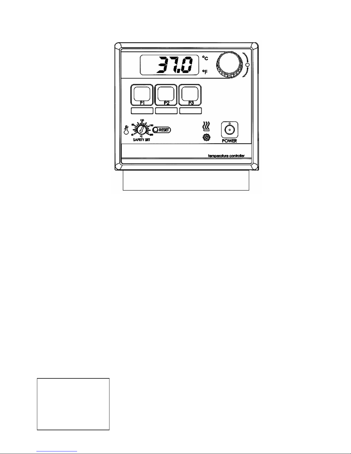
Section 4 - Standard Controller Information
17
14
16
15
4.1 Front and Rear Panels
10
1
2
3
4
11
9
8
7
12
6
5
13
Front View Rear View
1. Display 11. Pump Speed Switch
2. Preset Temperature Buttons 12. Identification Label
3. Safety Set Reset Button 13. Pump Inlet 2
4. Safety Set Indicator Knob 14. Reservoir Purge 2
5. Cooling Light 1 15. Pump Outlet 2
6. Power ON / OFF Button 16. AC Input
7. Heating Light 17. Circuit Breaker / AC Power Switch
8. °F Light
9. Select/Set Knob (Push to set, turn to adjust)
10. °C Light
1
Present on Refrigerating/Heating models only
2
Built in on reservoir models only
Page 13

4.2 Heater/Pump Assembly
1. Temperature Sensor
2. Pump Shaft and Impeller
3. Pump Outlet Nozzle1
4. Over-Temperature Sensor
5. Heater Coils
1
Rotates on Immersion Circulators
4.3 Specifications
Temperature Stability ±0.05°C
Readout Accuracy ±0.5°C
Over-Temperature Protection Yes, user-adjustable
Low-Liquid Protection Yes
Heater 1100W – 115V, 1600 W – 240V
1
3
2
4
5
Pump Speeds 2-speed, 9 liters per minute or 15 liters per minute
Environmental Conditions:
● Indoor Use Only ● Over Voltage: Category ll
● Maximum Altitude: 2000 meters ● Operating Ambient: 5° to 30°C
● Relative Humidity: 80% for temperatures to 30°C ● Pollution Degree: 2
● Class 1: Residential, Commercial, Light Industrial ● Class 2: Heavy Industrial
Section 5 – Operation
5.1 Circulator Location
Locate the Circulator on a level surface, free from drafts and out of direct sunlight. Do not place it
where there are corrosive fumes, excessive moisture, high room temperatures, or excessive dust is
present.
Refrigerating/Heating Circulators must be a minimum of four inches (102mm) away from walls or
vertical surfaces so air flow around the unit is not restricted.
To help prevent voltage drops, position the Circulator as close as possible to the power distribution
panel and a properly grounded outlet. The use of an extension cord is not recommended.
Warning: These units are equipped with over-temperature protection (Safety Set). A low liquid level
or failure to set the Safety Set and properly immerse the heater may result in heater burnout and triac
failure. While operating, do not allow the heater to contact any potentially flammable materials, such
as plastic racks or sides of plastic tanks, as a fire hazard may result.
Page 14

5.2 Reservoir Liquid Level
Fill the reservoir with the appropriate bath fluid. On Circulating Baths, the liquid level should be
sufficient to cover the heating coils, pump, over-temperature sensor, and at least one inch (25mm) of
the temperature sensor. On Immersion Circulators, the liquid level should be sufficient to fully
immerse the heater coils, over-temperature sensor, and pump outlet nozzle.
5.3 Power
An IEC power cord is provided with the Circulator. This power cord should be plugged into the IEC
receptacle on the rear of the Controller and then plugged into a properly grounded outlet. Make sure
that the power outlet is the same voltage and frequency indicated on the identification label on the
back of the Controller.
The use of an extension cord is not recommended. However, if one is necessary, it must be properly
grounded and capable of handling the total wattage of the unit. The extension cord must not cause
more than a 10% drop in voltage to the Circulator.
Once the unit has been connected to an appropriate electrical outlet, place the Circuit
Breaker/Power Switch on the rear of the Controller in the ON position. Four decimal points (….) will
appear on the digital display. DO NOT place the Power Switch on the front of the Controller ON until
the Safety Set has been adjusted to the desired temperature (see 5.4 below).
Indicated Voltage:
Volts/Phase/Frequency Operational Voltage Range Phase Frequency
100/ 1 / 60 90 to 110 Volts single 60 Hz
100/ 1 / 50 90 to 110 Volts single 50 Hz
120/ 1 / 60 110 to 130 Volts single 60 Hz
230/ 1 / 60 208 to 230 Volts single 60 Hz
240/ 1 / 50 220 to 240 Volts single 50 Hz
After filling the reservoir with fluid, you must set the Safety Set and the Software High Limit as
well as your desired control set point temperature.
5.4 Setting the Safety Set Set Point
The Safety Set feature automatically disconnects Controller power to the heater and pump in the
event that the reservoir liquid level drops too low or the Controller fails. The Safety Set is useradjustable between approximately 40° and 210°C. It should be set at least 5°C higher than the
Software High Limit temperature.
Use a flat blade screwdriver to rotate the Safety Set Indicator Knob to the desired temperature. Do
not force the knob beyond the stops at either end of the temperature value range.
Once the Safety Set temperature has been set, turn power to the Controller ON by pressing the
Power Switch on the front of the Controller. The pump will begin operating, the display will flash the
current temperature set point (tx.xx), the °C LED will light, and the current bath temperature will
appear on this display. Pump speed selection is made using the Pump Speed Selection Switch on
the rear of the Controller (see Section 2.3 or 3.3).
If power is disrupted because the Safety Set temperature was exceeded, place the Circuit
Breaker/Power Switch in the OFF position, press the Safety Set Reset Button, correct the problem
(low liquid level, incorrect Safety Set temperature, etc.), and then restore power.
Activation of the Safety Set during normal operation will display a fault (FLt 3) on the readout.
5.5 Selecting Temperature Units
The control set point and actual bath temperatures may be displayed in either °C or °F. The
factory-default is °C.
To change from °C to °F, place the Circuit Breaker/Power Switch on the rear of the Controller in
the OFF position and then press and hold the P2 Button while turning the power back ON.
Page 15

To change from °F to °C, place the Circuit Breaker/Power Switch in the OFF position and then press
and hold the P3 Button while turning the power back ON.
NOTE: When the temperature display units are changed, the Software High Limit value and all
temperature presets revert to the factory-default values. If a calibration value has been entered, the
value will be retained.
5.6 Setting the Software High Limit
This feature provides additional safety and protection by allowing a selectable upper temperature
limit set point. To avoid an unwanted shutdown during regular operation, the high limit value should
be set at least 5°C higher than the selected control temperature
To set the Software High Limit temperature set point, press the P2 and P3 keys simultaneously and
repeat until (Hxxx) appears on the display. This is the current Software High Limit value. It is factory
set at 152°C.
To change the displayed value, press and turn the Select/Set Knob until the desired Software High
Limit set point value is displayed. A clockwise rotation increases the value; a counterclockwise
rotation decreases the value. Press the Select/Set Knob a second time to accept the new value and
return to normal operation.
If the Software High Limit value meets or exceeds the control temperature set point, (E-H1) will flash
on the display. If this occurs, enter a higher value for the Software High Limit or reduce the control
temperature set point.
If the actual bath temperature reaches the Software High Limit setpoint, (FLt1) will flash on the
display. Should this occur, the Controller will automatically remove power from the heater and, in
Refrigerating/Heating units, the compressor as well. The pump will continue to operate.
Once the problem is corrected (bath temperature reduced or Software High Limit value increased),
press the Power button to clear the message.
5.7 Setting the Set Point Temperature
Press and release the Select/Set Knob. The decimal point flashes to indicate that the set point
temperature can be changed.
Turn the Select/Set Knob until the desired temperature set point is displayed. A clockwise rotation
increases the setting; a counterclockwise rotation decreases the setting. Press the Select/Set Knob
a second time to accept the displayed value. The decimal point stops flashing and the display will
indicate the actual bath temperature. Allow sufficient time for the bath to stabilize at the desired
temperature before making any adjustments to set point temperature.
NOTE: The unit will automatically accept the displayed set point after approximately 10 seconds of
inactivity, even if the Select/Set Knob was not pressed.
The set point temperature may be checked at any time by pressing the Select/Set Knob.
If the set point temperature cannot be raised, it is possible that the Software High Limit value is set
lower than the desired control temperature set point. Reset the Software High Limit value to 5°C or
more above the desired set point temperature.
5.8 User-Defined Preset Temperatures
With the unit on, press the desired Preset Button — P1, P2, or P3. The
LED associated with the selected Preset Button will begin to flash.
Rotate the Select/Set Knob to the desired temperature set point.
Press the selected Preset Button a second time to enter the new set
point. The new set point temperature will not be saved unless the
Preset Button is pressed.
The LED associated with Preset Button lights continuously whenever
that preset value is controlling bath temperature. If more than one
Preset Button is set at a given temperature set point, the LED
associated with all Preset Buttons with that set point will light.
Page 16

5.9 Local Lockout Feature
This feature enables the user to lock all controls on the controller. While the feature is activated, the
unit will remain running at the current settings.
To activate the local lockout feature, press and hold the Select/Set Knob for 10 seconds. Once
locked, the screen will read LLo. When locked, the setpoint decimal point will not flash as usual.
Press and hold the Select/Set Knob again for 10 seconds to unlock the controls. Once unlocked, the
screen will read CAn.
5.10 Stick-on Strips for Preset Buttons
The Standard Controller is supplied with two stick-on
strips that can be applied beneath the Preset Buttons.
These strips are removable and can be reapplied.
The user can write the set point temperature associated
with each Preset Button on this strip. The use of an
erasable medium, such as dry erase marker or flair tip
pen is recommended. The former can be wiped off with a
dry cloth or tissue; the later can usually be removed with
simple glass cleaner and a cloth or tissue. Do not use a
permanent marker or ballpoint pen. Always do an ink
test before writing on these strips.
5.11 Auto-Refrigeration Operation
Auto-Refrigeration selects the temperature at which refrigeration is activated. For most applications,
a set point 15°C above room temperature is recommended.
The stick-on strip fits beneath the
controller’s Preset Buttons. It is
removable and reapplicable.
Cool Command Refrigeration
Refrigerating/Heating Circulators with 13 and 28 liter reservoirs feature the advanced Cool
Command™ modulating refrigeration control system. Cool Command Auto-Refrigeration has a
broader range of control — from +20°C to 85°C — than conventional refrigeration. Additionally, it
allows the refrigeration system to turn on at a fluid temperature up to 150°C when the temperature
set point is changed to or below the Auto-Refrigeration set point (85°C maximum). As a result, bath
fluids cool more quickly.
Conventional refrigeration
Refrigerating/Heating Circulators with 6 liter reservoirs use a conventional refrigeration system. The
Auto-Refrigeration control range on these is from +20°C to 70°C. The refrigeration system will turn
on when the bath fluid temperature is at or above the Auto-Refrigeration set point (70°C maximum).
Setting the Auto-Refrigeration Temperature:
Press the P2 and P3 Buttons simultaneously and repeat until the current Auto-Refrigeration set point
temperature appears on the display (Axxx).
To change the displayed value, press and turn the Select/Set Knob until the desired temperature is
displayed. Press the Select/Set Knob a second time to enter the value and return to normal
operation.
The factory default Auto-Refrigeration value is 40°C.
Page 17

5.12 Controller Display Messages
Display Description Action Required
….
tx.xx Power up self-test Normal — Appears momentarily at startup
oCx.x Calibration offset value Normal — Current calibration offset value; refer to section 6.1
Hxxx Software High Limit value Normal — Current Software High Limit value; refer to section 5.6
Axxx Auto-Refrigeration set point value
E-H1 Software High Limit set point too low
FLt 1 Software High Limit value exceeded
FLt 2 EEPROM reset
FLt 3 Safety Set temperature exceeded
FLt 4 Heating Triac failure Error — Service required
FLt 5 Probe failure Error — Service required
FLt 6
Standby mode
i2c error — Communication failure to
modulation board
Normal — Indicates that the Circuit Breaker/Power Switch is ON
and the Controller Power Switch is OFF
Normal — Current Auto-Refrigeration set point; refer to section
5.10 (Appears only on Refrigerating/Heating Circulators)
Error — The value entered is below the control temperature set
point. Refer to Setting Software High Limit, section 5.6
Error — Set a Software High Limit value higher, then turn main
power to the unit OFF and back ON; refer to section 5.6
Error — Turn Circuit Breaker/Power Switch OFF, hold P3 Button,
and then turn the Circuit Breaker/Power Switch back ON
Error — Check fluid level
Check fluid temperature and set point
Ensure that OTP set point is higher than fluid set point or
increase to maximum
Turn Circuit Breaker/Power Switch OFF, press Safety Set Reset
Button, and then turn the Circuit Breaker/Power Switch back ON
Error — Service required (Appears only on Refrigerating/Heating
Circulators)
Section 6 - Calibration and Maintenance
6.1. Calibration
Calibration allows the user to match the Controller’s bath temperature display to an external
reference thermometer. Calibration is performed as follows:
Set the desired operating fluid temperature set point and allow temperature to stabilize.
Press the P2 and P3 simultaneously and release and repeat until the display reads (oCx.x). Press
P1 and hold until (Cal) is displayed. This will take about 2 seconds.
At one second intervals, the displayed value will alternate between the actual bath fluid temperature
and the current offset value, which is the difference between the factory calibration setting and the
user’s reference temperature sensor. The maximum offset is ±0.9°C from factory calibration.
To change the calibration offset value, rotate the Select/Set Knob until the display matches the
reading on the reference temperature sensor. The display will continue to alternate between the
offset value and the calibrated display temperature.
Press the Select/Set Knob or the P1 Button to accept the entered value. When the new calibration is
stored and the mode is exited, (dONE) will appear on the display.
NOTE: The displayed offset value will also be accepted if there no activity for 20 seconds.
6.2 Heater
The heater should be kept clean. If deposits build up on the heater, they may be removed by
scrubbing with a non-metallic (plastic) abrasive pad. Do not use steel wool.
Page 18

6.3 Pump Motor
The pump bearings are permanently lubricated with high-temperature silicone grease and do not
require additional lubrication. Should the bearings become noisy, replacement of the entire pump
motor is recommended. This will reduce repair labor costs and retain fluid pumping reliability.
A replacement pump and motor mounting kit is available (see Section 10 - Replacement Parts).
6.4 Cleaning
Only mild detergents and water or an approved cleaner should be used on the painted and stainless
steel surfaces of the Circulator. Do not allow cleaning liquids or sprays to enter the Controller vents.
A concentrated bath cleaner is available that can be used to remove mineral deposits from the
reservoir. See Section 10 - Replacement Parts.
6.5 Maintaining Clear Bath Water
When water is used as the bath fluid, optimal conditions are present for algae growth. To prevent
algae contamination and minimize the need for draining the reservoir, an algicide should be used.
See Section 10 - Replacement Parts.
Do NOT use chlorine bleach in the reservoir or on any pump parts.
6.6 Condenser, Air Vents, and Reusable Filter
(Refrigerating/Heating Circulators Only)
To keep the refrigeration system operating at optimum cooling capacity, the
condenser, the front and back air vents, and reusable filter should be kept free of
dust and dirt. They should be checked on a scheduled basis and cleaned as
required.
The reusable filter is easily accessed from the bottom/front of the unit. Turn the
filter-retaining clip away from the filter cutout and remove the filter as shown by
photo 6.6. Use a mild detergent and water solution to wash off any accumulated
dust and dirt and then rinse thoroughly and dry before reinstalling.
Photo 6.6
Section 7 - Troubleshooting
7.1 Unit Will Not Operate (no heat, cooling, or pumping)
• Check that the power cord is plugged in to an operating electrical outlet.
• Check that the Circuit Breaker/Power Switch is ON.
• Check that the Controller Power Switch is ON.
• Check that the Safety Set temperature is higher than the control temperature set point.
• Turn power off, press the Safety Set Reset button, and restore power.
7.2 No Pumping
• Check the fluid level of the bath to be sure the pump head is covered with fluid.
• If the pump motor does not spin, verify that the Pump Speed Switch is either in the HIGH or LOW
position. If it is in the middle, the pump will not receive power.
• Check the pump impeller for obstructions (it should turn freely).
7.3 Slow or Insufficient Pumping
• Check for low line voltage, particularly when the heater is on.
• Check for too small of a hose diameter (closed loop applications).
• Check for too high of a fluid viscosity.
Page 19

7.4 No Heating
• Verify that the unit is pumping properly.
• If the heat light is not lit, check the control temperature set point and bath temperature to verify
that heating is required.
• Verify that the liquid in the bath covers the heater coils.
• Check that the Software High Limit value has not been exceeded (FLt 1 appears on the display).
7.5 Insufficient Heating
• Verify that the unit is pumping properly.
• Check for proper line voltage.
• Check for excessive external cooling load on unit.
• At higher temperatures, insufficient heating could be due to excessive heat loss from tanks, hoses,
or vapor from the tank.
• Check that the heat demand from connected devices or experiments does not exceed the heating
capabilities of the unit.
• Allow sufficient time for bath temperature to stabilize when changes in heat load or set point are
made.
7.6 No Cooling or Insufficient Cooling
• Check that the Cooling switch is ON.
• If the cooling light is not lit, check the control temperature set point and bath temperature to verify
that cooling is required.
• Check for low or high line voltage.
• Check for blocked airflow through ventilation screens.
• Check ambient air temperature. Refrigeration unit should not be operated above 32°C ambient
temperature as high air temperature may cause the refrigeration compressor to temporarily shut
down.
• Check for excessive heat being transferred to the bath liquid as this may exceed the cooling
capacity of the refrigeration system.
7.7 Triac Failure
• (FLt4) appears on the display, indicating that the heater triac has failed or line supply voltage has
a source of extreme interference from other equipment. Plug the unit into another power source.
If it still displays triac failure, a triac or triac driver needs replacement.
Page 20

Section 8 - Reservoir Fluids
Depending on your needs, a variety of fluids can be used with your Circulator. No matter what bath
medium is selected, it must be chemically compatible with the reservoir and with the 300 series
stainless steel in the pump and heater. It must also be suitable for the desired temperature range.
Always use fluids that satisfy safety, health, and equipment compatibility requirements
For optimum temperature stability, the fluid’s viscosity should be 50 centistokes or less at its lowest
operating temperature. This permits good fluid circulation and minimizes heating from the pump.
For temperatures from 10°C to 90°C, distilled water is recommended. For temperatures below 10°C,
a mixture of laboratory grade ethylene glycol and water should be used. Do not use deionized water.
The following chart is intended to serve as a guide in selecting a bath fluid for your application. For
optimum temperature stability and low vaporization, be sure to stay within the fluid's normal
temperature range.
You are responsible for proper selection and use of the fluids.
FLUID DESCRIPTION SPECIFIC HEAT NORMAL EXTREME
@25°C RANGE RANGE
Distilled Water 1.00 10° — 90°C 2° — 100°C
Ethylene Glycol 30% / Water 70% .90 0° — 95°C -15° — 107°C
Ethylene Glycol 50% / Water 50% .82 -20° — 100°C -30° — 100°C
Dynalene-HC 50 .76 -50° — 60°C -62° — 60°C
DC200, 5 cs Silicone Oil .32 -35° — 65°C -50° — 125°C*
DC200, 10 cs Silicone Oil .34 -20° — 80°C -35° — 165°C*
DC200, 20 cs Silicone Oil .36 0° — 100°C -10° — 230°C*
DC200, 50 cs Silicone Oil .39 50° — 150°C 5° — 270°C*
DC510, 50 cs Silicone Oil .39 50° — 150°C 5° — 270°C*
DC550, 125 cs Silicone Oil .42 100° — 200°C 80° — 232°C*
DC710, 500 cs Silicone Oil .45 150° — 250°C 125° — 260°C*
*WARNING - Fluid’s flash point temperature
DC fluids are manufactured by Dow Corning.
Dynalene HC is a registered TM of Advanced Fluid Technology Inc.
Avoid extreme range operation.
DO NOT USE the following fluids:
1. Automotive antifreeze with additives**
2. Hard tap water**
3. Deionized water with a specific resistance > 1 meg ohm
4. Any flammable fluids
5. Concentrations of acids or bases
6. Solutions with halides: chlorides, fluorides, bromides, iodides or sulfur
7. Bleach (Sodium Hypochlorite)
8. Solutions with chromates or chromium salts
** At temperatures above 40°C, additives or mineral deposits can adhere to the heater. If deposits
are allowed to build up, the heater may overheat and fail. Higher temperatures and higher
concentrations of additives will hasten deposit build up
Warning: Do not use a flammable liquid as a bath medium as a fire hazard may result.
Page 21

Application Notes
At a fluid's low temperature extreme:
1. The presence of ice or slush adversely affects temperature stability.
2. A viscosity above 10 centistokes adversely affects temperature uniformity.
3. A high fluid viscosity and high pump speed adds heat to the fluid being pumped.
At a fluid's temperature above ambient without refrigeration:
1. To avoid friction heating of the fluid, the viscosity of the fluid should be 10 centistokes or less
and within 15°C of room temperature.
2. Heat loss should be encouraged by uncovering the fluid and lowering the pump speed.
At fluid's high temperature extreme:
1. Heat loss from vapor adversely affects temperature stability.
2. To prevent the accumulation of vapors inside the room, the reservoir may need to be placed
in a fume hood.
3. Use a cover and/or floating hollow balls to help prevent heat and vapor loss.
4. Replenish fluid lost from vapor frequently.
Section 9 - Service and Technical Support
If you have followed the troubleshooting steps outlined in Section 7 and your Circulator still fails to
operate properly, contact the supplier from whom the unit was purchased. Have the following
information available for the customer service person:
— Model, Serial Number, and Voltage (from back panel label)
— Date of purchase and purchase order number
— Supplier’s order number or invoice number
— A summary of the problem
Page 22

Section 10 - Replacement Parts
Description Part #
Lab Algicide, concentrate, 8 oz. 004-300040
Bath Cleaner, concentrate, 8 oz. 004-300050
Bath Cleaner, concentrate, 16 oz. 004-300052
Dynalene HC™, 1 gallon 060330
Dow Corning® 510, 1 gallon 060326
Dow Corning® 550, 1 gallon 060327
Dow Corning® 710, 1 gallon 060328
Assembly, Front Bezel 06, 120V 510-260
Assembly, Front Bezel 06, 240V 510-261
Pump Motor (Refrigerating/Heating and Heating Only models), 120V 525-525
Pump Motor (Refrigerating/Heating and Heating Only models), 240V 525-526
Pump Motor (Immersion Circulators), 120V 525-527
Pump Motor (Immersion Circulators), 240V 525-528
Heater, Tubular, 1.1kw, 120V 215-067
Heater, Tubular, 2.2kw, 240V 215-416
Fan, Refrigeration, 120V 215-196
Fan, Refrigeration, 240V 215-197
Temperature Probe 200-136
Circuit Breaker 215-330
AC Mains Connector, 15A 215-397
Switch, Slide, for Pump High/Low Speed 235-008
Manual, Standard Controller Operators 110-227
IEC Power Cord 120V 225-227
IEC Power Cord 240V 225-228
 Loading...