

Page 1
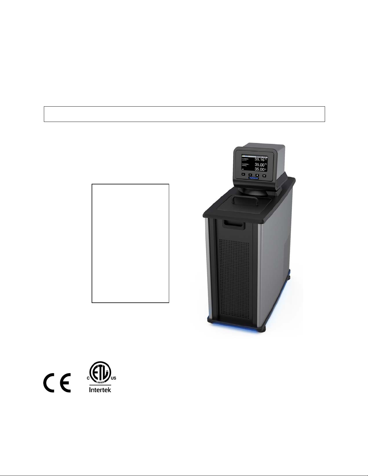
Circulating Baths with
Performance Digital Temperature
Controller
Operator’s Manual
Models:
PD07R-20
PD07R-40
PD7LR-20
PD15R-30
PD15R-40
PD20R-30
PD28R-30
PD45R-20
PD07H200
PD15H200
PD20H200
PD28H200
110-515 PSC/EN 10.5.11
Page 2

Table of Contents
Introduction .................................................................................................................................................4
Circulating Baths with Performance Digital Temperature Controller........................................................4
General Safety Information....................................................................................................................... 5
Safety Recommendations.........................................................................................................................6
Regulatory Compliance & Testing ............................................................................................................ 7
Unpacking Your Circulator........................................................................................................................ 8
Contents ...................................................................................................................................................8
Controls & Components............................................................................................................................9
Performance Digital Controller .............................................................................................................9
Refrigerating/Heating Baths ...............................................................................................................10
Heating Only Baths.............................................................................................................................11
Quick-Start.................................................................................................................................................12
Installation & Startup................................................................................................................................13
General Site Requirements .................................................................................................................... 13
Adding Liquid to the Bath Reservoir ....................................................................................................... 14
Pump Inlet and Outlet Connections........................................................................................................15
External Closed Loop Circulation ...........................................................................................................15
Open Loop Circulation............................................................................................................................16
Refrigeration Control Connections (Refrigerating/Heating Circulators only)..........................................17
Electrical Power ...................................................................................................................................... 17
Refrigerating / Heating Circulators .....................................................................................................17
Heat Only Circulators and Open Bath Systems ................................................................................. 18
Communication.......................................................................................................................................19
USB Communication ..........................................................................................................................20
Ethernet .............................................................................................................................................. 20
RS232 / RS485 Serial Communication .............................................................................................. 20
External (P2) Temperature Probe ..........................................................................................................20
Controller Setup........................................................................................................................................21
Power...................................................................................................................................................... 21
Safety Set Temperature..........................................................................................................................21
Basic Operation.........................................................................................................................................23
Turning Your Circulator On..................................................................................................................... 23
Controller & Touch Screen Navigation ...................................................................................................23
Controller Navigation..........................................................................................................................23
Touch Screen Navigation ................................................................................................................... 23
Menu Structure .......................................................................................................................................25
Main Operational Displays (Home Screens) ..........................................................................................26
Status Bar...........................................................................................................................................26
Home Screens....................................................................................................................................27
Adjusting the Temperature Set Point...................................................................................................... 28
General Operational Settings .................................................................................................................30
Pump Speed.......................................................................................................................................31
Unit .....................................................................................................................................................31
Sound .................................................................................................................................................31
Language............................................................................................................................................ 31
Display................................................................................................................................................31
Lock Out .............................................................................................................................................31
Auto Restart........................................................................................................................................ 31
Personalize.........................................................................................................................................31
Display Filter.......................................................................................................................................32
SHC (Specific Heat Capacity) ............................................................................................................32
Time and Date Settings .......................................................................................................................... 32
110-515 PSC/EN 1
Page 3

Time.................................................................................................................................................... 32
Date .................................................................................................................................................... 32
Safety Settings........................................................................................................................................ 33
High Limit / Low Limit Temperatures.................................................................................................. 33
High Alarm / Low Alarm Temperatures ..............................................................................................33
Control .................................................................................................................................................... 34
Probe Control .....................................................................................................................................34
Auto Cool............................................................................................................................................34
Fluid Type...........................................................................................................................................35
P2 - P1................................................................................................................................................ 35
PID...................................................................................................................................................... 35
External Cooling Control ....................................................................................................................36
Send Internal Data USB/WEB............................................................................................................36
Reset Memory and Reboot ................................................................................................................36
Communications and Data Logging .......................................................................................................36
Ethernet .............................................................................................................................................. 36
RS232................................................................................................................................................. 37
USB ....................................................................................................................................................37
RS485................................................................................................................................................. 37
Timer....................................................................................................................................................... 38
Enabling / Disabling the Local Lock Out.................................................................................................39
Advanced Operation.................................................................................................................................40
Event Creation ........................................................................................................................................ 40
Creating an Event............................................................................................................................... 40
Previewing an Event........................................................................................................................... 43
Editing an Event ................................................................................................................................. 43
Saving and Uploading Events ............................................................................................................45
Scheduling an Event...............................................................................................................................47
Manual Start .......................................................................................................................................47
Automatic Start ................................................................................................................................... 47
Running an Event ...................................................................................................................................49
Creating and Installing a Personalized Home Screen............................................................................50
Circulator Monitoring and Control Using an Internet Browser ................................................................ 51
Calibration..................................................................................................................................................52
Restoring All Factory Default Values......................................................................................................54
System Restoration ..................................................................................................................................54
Changing Your Circulator's Viewing Angle............................................................................................55
Inert Gas Purge .........................................................................................................................................55
Tap Water Cooling ....................................................................................................................................55
Reservoir Cover Storage..........................................................................................................................56
Routine Maintenance & Troubleshooting...............................................................................................57
Service Sub-Menu ..................................................................................................................................57
Diagnostic Data Logging.........................................................................................................................58
Maintaining Clear Bath Water................................................................................................................. 58
Draining the Bath Reservoir ...................................................................................................................59
Checking the Over-Temperature / Low Liquid Level Safety Systems....................................................60
Cleaning Your Circulator.........................................................................................................................61
Temperature Controller Removal and Re-Installation ............................................................................ 62
Removal .............................................................................................................................................62
Re-Installation..................................................................................................................................... 63
Calibrating the Touch Screen ................................................................................................................. 64
Display Module Firmware Updates......................................................................................................... 64
Warning and Fault Messages.................................................................................................................65
110-515 PSC/EN
2
Page 4

Warnings ............................................................................................................................................65
Faults..................................................................................................................................................66
Troubleshooting Chart ............................................................................................................................67
Technical Information...............................................................................................................................69
Performance Specifications .................................................................................................................... 69
Reservoir Fluids......................................................................................................................................70
Application Notes....................................................................................................................................72
Tubing and Fitting Temperature Ranges................................................................................................ 72
Fluid Compatibility ..................................................................................................................................72
RS232/RS485 Communications.............................................................................................................73
Remote ON / OFF................................................................................................................................... 75
USB Data Logging .................................................................................................................................. 75
USB B Setup, Monitoring, and Control ................................................................................................... 76
Ethernet Configuration............................................................................................................................ 76
Direct Computer to Controller Configuration ...................................................................................... 76
Wired or Wireless Network Configuration ..........................................................................................77
TCP Control Configuration .................................................................................................................78
External Cooling Control......................................................................................................................... 79
Equipment Disposal (WEEE Directive)...................................................................................................81
Replacement Parts & Accessories..........................................................................................................82
PolyScience Circulating Bath Fluids ......................................................................................................84
Service & Technical Support ...................................................................................................................85
Warranty.....................................................................................................................................................85
110-515 PSC/EN
3
Page 5
Introduction
Thank you for choosing this Circulating Bath with Performance Digital Temperature Controller. It is
intended for the precise temperature control of suitable liquids in a reservoir. Extremely easy to use and
maintain, it combines design innovation with highly intuitive operation to deliver convenient and versatile
liquid temperature control for a wide range of applications.
WARNING: PolyScience Circulating Baths are not intended for directly controlling the temperature of
foods, pharmaceuticals, medicines, or other objects which may be ingested by or injected in humans
or animals. Any such objects must be isolated from contact with the bath fluid and bath surfaces.
Here are some of the features that make your Circulating Bath so user-friendly:
Intuitive touch screen operation
Selection of seven different temperature displays, including time-temperature graphing
Powerful variable-speed pressure/suction pump with external circulation capability
180° viewing radius (Swivel 180™ rotating control head)
DuraTop™ heat and chemical resistant top plate
LidDock™ self-storing reservoir cover (integrated baths only)
Built-in temperature protection
Suitable for use with Class III flammable bath fluids per DIN 12876-1
It will take you very little time to get your new Circulating Bath installed and running. This Operator’s
Manual is designed to guide you quickly through the process. We recommend that you read it thoroughly
before you begin.
Circulating Baths with Performance Digital Temperature Controller
Model Type
PD07R-20 Refrigerating/Heating 7 liter -20° to 200°C -4° to 392°F
PD07R-40 Refrigerating/Heating 7 liter -40° to 200°C -40° to 392°F
PD7LR-20 Refrigerating/Heating 7 liter -20° to 200°C -4° to 392°F
PD15R-30 Refrigerating/Heating 15 liter -30° to 200°C -22° to 392°F
PD15R-40 Refrigerating/Heating 15 liter -40° to 200°C -40° to 392°F
PD20R-30 Refrigerating/Heating 20 liter -30° to 200°C -22° to 392°F
PD28R-30 Refrigerating/Heating 28 liter -30° to 200°C -22° to 392°F
PD45R-20 Refrigerating/Heating 45 liter -25° to 135°C
PD07H200 Heating Only 7 liter Ambient +10° to 200°C Ambient +20° to 392°F
PD15H200 Heating Only 15 liter Ambient +10° to 200°C Ambient +20° to 392°F
PD20H200 Heating Only 20 liter Ambient +10° to 200°C Ambient +20° to 392°F
PD28H200 Heating Only 28 liter Ambient +10° to 200°C Ambient +20° to 392°F
1. Maximum operating temperature at which ±0.005°C temperature stability can be maintained; Performance Digital Controller is capable of higher
temperatures.
Reservoir
Capacity
Temperature Range
°C °F
(1)
-13° to 275°F
(1)
110-515 PSC/EN
4
Page 6
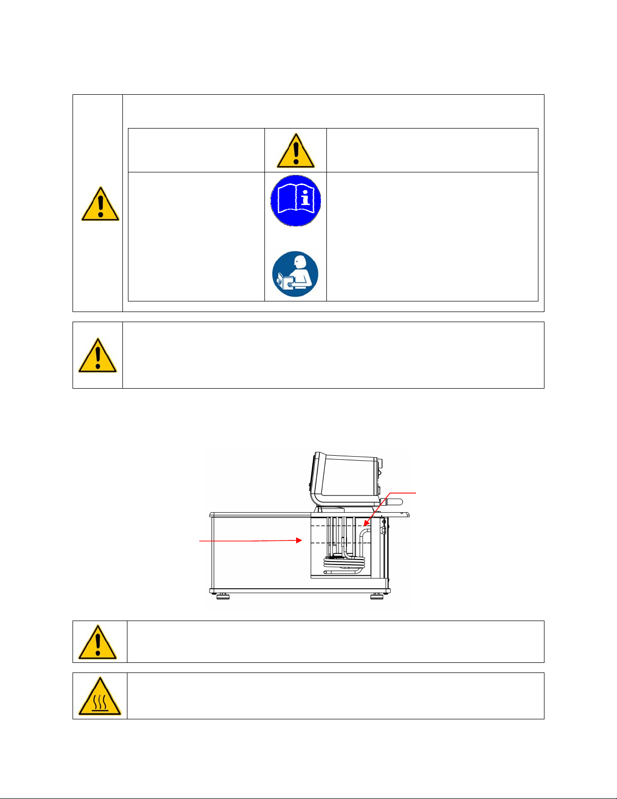
General Safety Information
When installed, operated, and maintained according to the directions in this manual and common safety
procedures, your Circulating Bath should provide safe and reliable temperature control. Please ensure
that all individuals involved in the installation, operation, or maintenance of this Circulating Bath read this
manual thoroughly prior to working with the unit.
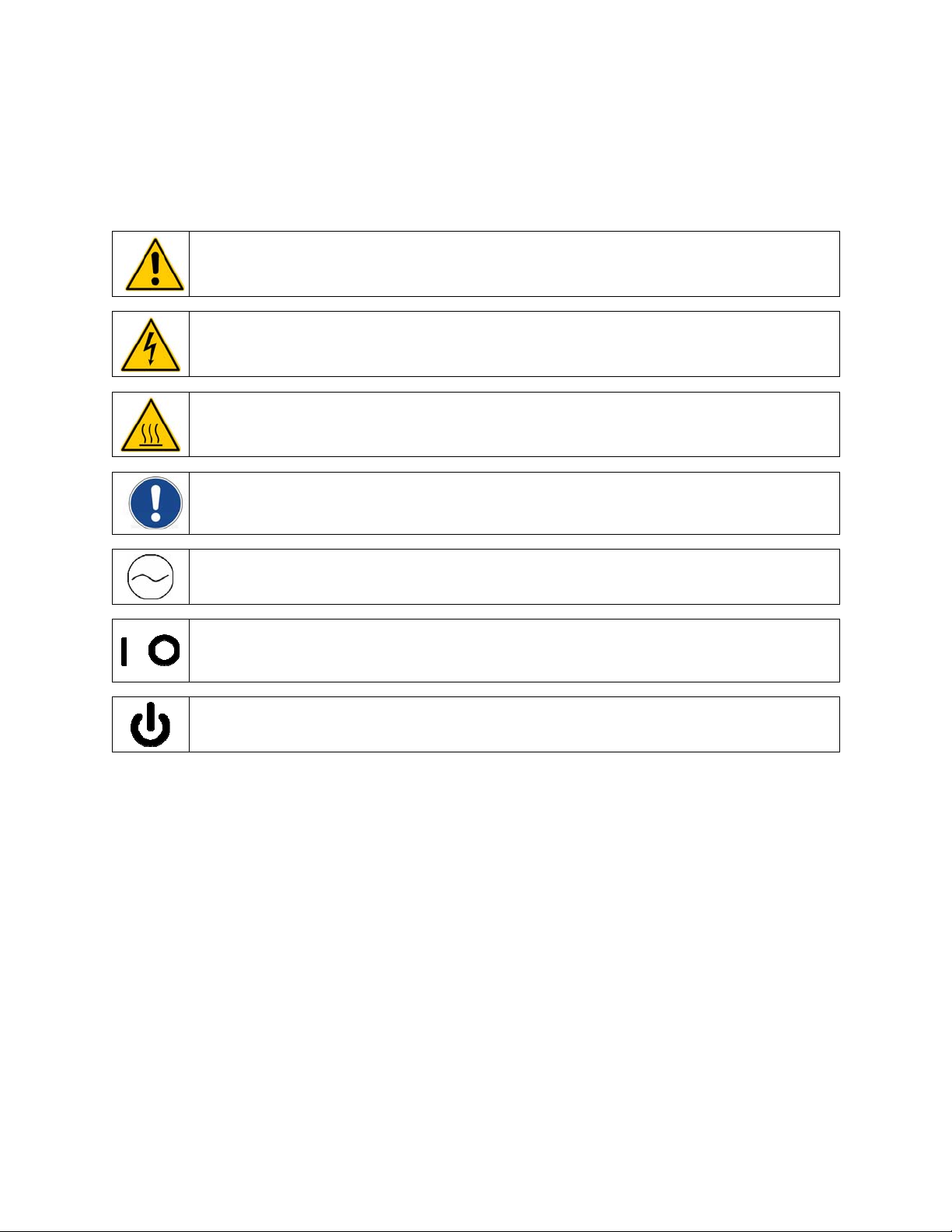
This symbol alerts you to a wide range of potential dangers.
This symbol advises you of danger from electricity or electric shock.
This symbol indicates that a hot surface may be present.
This symbol marks information that is particularly important.
/
This symbol indicates alternating current.
These symbols on the Power Switch / Circuit Breaker indicate that they place the main power supply
ON / OFF.
This symbol on the Power Key indicates that it places the unit in a standby mode. It DOES NOT fully
disconnect the unit from the power supply.
Read all instructions pertaining to safety, set-up, and operation.
Proper operation and maintenance is the user’s responsibility.
110-515 PSC/EN
5
Page 7
Safety Recommendations
To prevent injury to personnel and/or damage to property, always follow your workplace’s safety
procedures when operating this equipment. You should also comply with the following safety
recommendations:
WARNING:
This Circulating Bath is suitable for use with Class III flammable fluids per DIN 12876-1. A fire
hazard may be present.
Be aware of the chemical hazards that may be associated with the bath fluid used. Observe all
safety warnings for the fluids used as well as those contained in the material safety data sheet.
Explosive gas mixtures may accumulate if used with insufficient ventilation. Use this Circulating
Bath in a well ventilated area or beneath a suitable fume hood only.
Use only recommended bath fluids; see Technical Information in the rear of this manual for
recommended fluids.
Use only non-acid bath fluids.
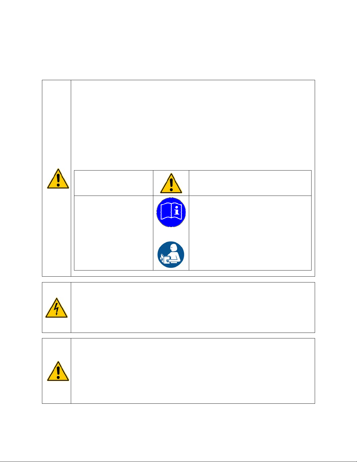
WARNING: When using Class III flammable fluids per DIN 12876-1, the user must attach the
following warning labels to the front of the unit so that they are well visible:
Warning Label
W09
Colors: Yellow/black
Mandatory Label
M018
Colors: Blue/white
or
Semi S1-0701
Table A1-2 #9
Colors: Blue/white
WARNING:
Always connect the power cord on this Circulator to a grounded (3-prong) power outlet. Make
certain that the outlet is the same voltage and frequency as your unit.
Never operate the Circulator with a damaged power cord.
Always turn the Circulator OFF and disconnect mains power before performing any maintenance or
service.
WARNING:
Never operate the Circulator without bath fluid in the reservoir. Periodically check the reservoir to
ensure that the liquid depth is within acceptable levels. Always refill the reservoir using the same
bath fluid type that is already in the reservoir. Bath oil must not contain any water contaminants
and should be preheated to the actual bath temperature before adding as there is an explosion
hazard at high temperatures.
Always drain all fluid from the reservoir before moving or lifting your Circulator. Be sure to follow
your organization’s procedures and practices regarding the safe lifting and relocation of heavy
objects.
Danger Area.
Attention! Observe instructions
(operating manual, safety data sheet)
Carefully read the user information prior to
beginning operation.
Scope: EU
Carefully read the user information prior to
beginning operation.
Scope: NAFTA
110-515 PSC/EN
6
Page 8
WARNING:
Always allow the bath fluid to cool to ambient temperature before draining.
The reservoir cover, top deck, and/or external pump connections may become hot with continuous
use. Exercise caution when touching these parts.
Always keep within the 85°C maximum operating temperature limit if using a polycarbonate tank.
WARNING: It is the user’s responsibility to properly decontaminate the unit in the event hazardous
materials are spilled on exterior or interior surfaces. Consult manufacturer if there is any doubt
regarding the compatibility of decontamination or cleaning agents.
Regulatory Compliance & Testing
This equipment is compliant with the European Directive 2002/95/EC and its latest amendments on
Restrictions on Hazardous Substances (RoHS) and below the given limits of hazardous substances.
ETL Intertek (60 Hz units)
UL 61010-1 / CSA C22.2 No. 61010-1 — Safety Requirements for Measurement, Control, and
Laboratory Use; Part 1: General Requirements
UL 61010A-2-010 / CSA C22.2 No. 61010-2-010:04 — Safety Requirements for Measurement, Control,
and Laboratory Use; Part 2-010: Particular Requirements for Laboratory Equipment for the Heating of
Materials
UL 61010A-2-051 / CSA C22.2 No. 61010-2-051:04 — Safety Requirements for Measurement, Control,
and Laboratory Use; Part 2-051: Particular Requirements for Laboratory Equipment for the Mixing and
Stirring
CE (all units)
EC Low Voltage Directive 2006/95/EC
EC Electromagnetic Compatibility Directive 2004/108/EC
IEC 61010-1-2001
IEC 61010-2-2001
IEC 61326:2005 / EN 61326 : 2006
110-515 PSC/EN
7
Page 9
Unpacking Your Circulator
Your Circulator was packed in a special carton or cartons. You should keep the packaging, along with all
packing materials, until the unit has been installed and you are certain it is working properly.
CAUTION: Remove any loose packing material that may have fallen into the heater/pump housing
during shipping. Before powering up, check that nothing remains around the heater or Circulator
pump.
We recommend that you begin using your Circulator immediately to confirm proper operation, since
beyond one week you may be eligible for warranty repair only (rather than replacement). You’ll find
complete warranty information in the back of this manual.
WARNING: Keep unit upright when moving. Be sure to follow your company’s procedures and
practices regarding the safe lifting and relocation of heavy objects.
Contents
The items included with your Circulator will vary depending on which model Circulating Bath you
purchased.
Refrigerating / Heating Bath Heating Only Bath
Resource Disk with
Operator’s Manual
Reservoir Cover
3-ft / 0.91 m IEC to IEC
Power Cord
6-ft / 1.82 m IEC to Mains
Power Cord
Refrigeration Control Cable ●
Fittings
Cooling Coil N/A Integral
Certificate of Compliance
Flash Drive
Pt100 External Temperature
Probe
Quick-Start Guide
1. 60Hz and 50Hz models
2. 50Hz models only
● ●
● ●
●
● ●
(2)
(1)
(1)
(1)
1/4 in. NPT to 3/16 in. barbed adapter
1/4 in. NPT to 1/4 in. barbed adapter
1/4 in. NPT to 3/8 in. barbed adapter
1/4 in. NPT to M16 barbed adapter
● ●
● ●
● ●
● ●
110-515 PSC/EN
8
Page 10
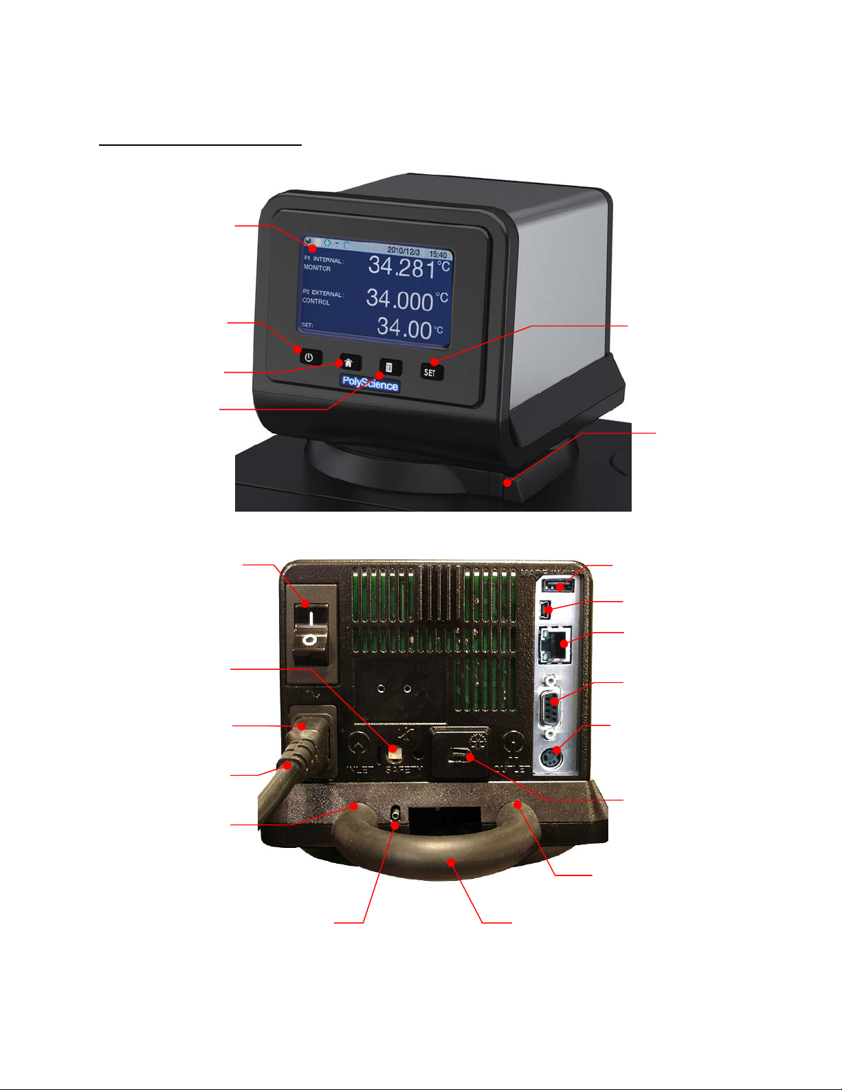
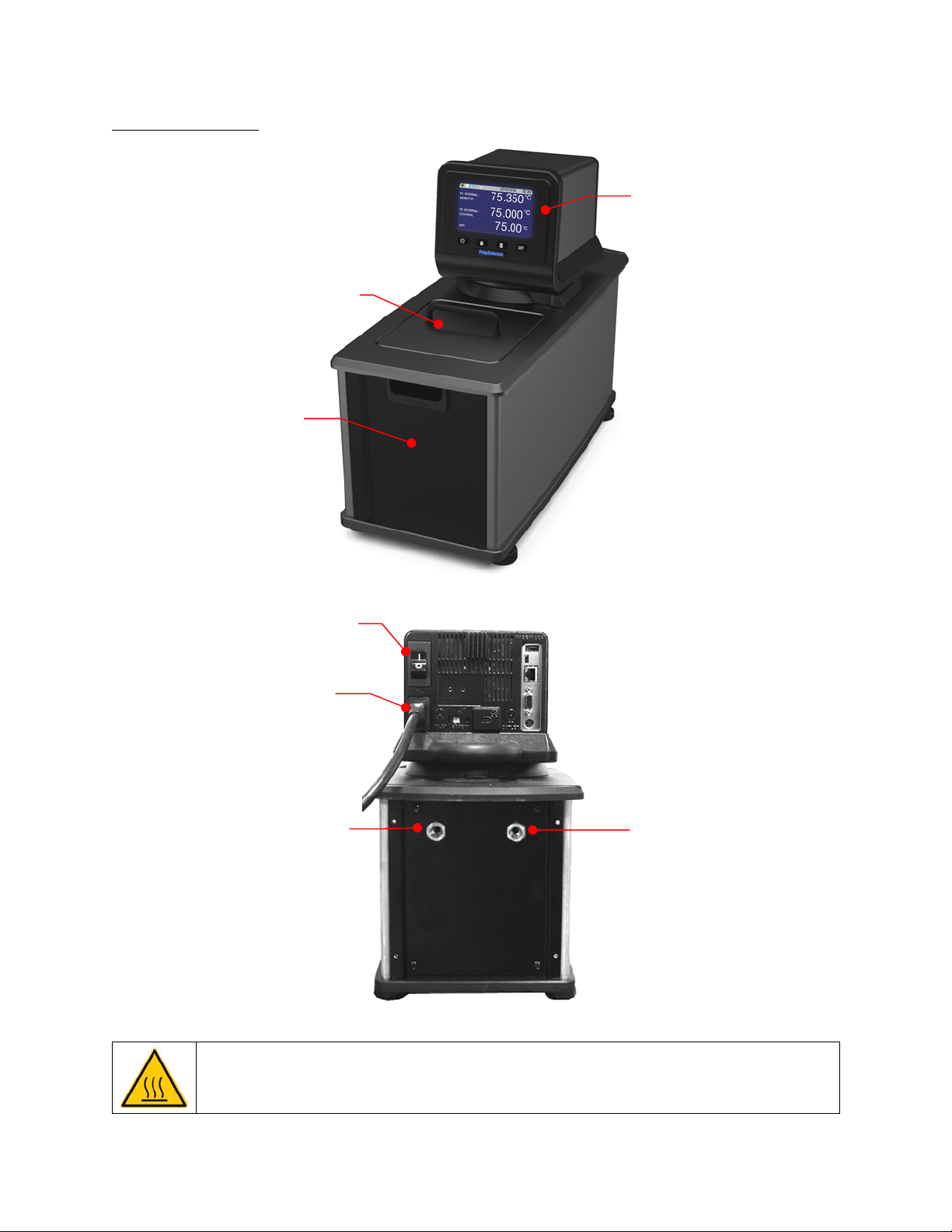
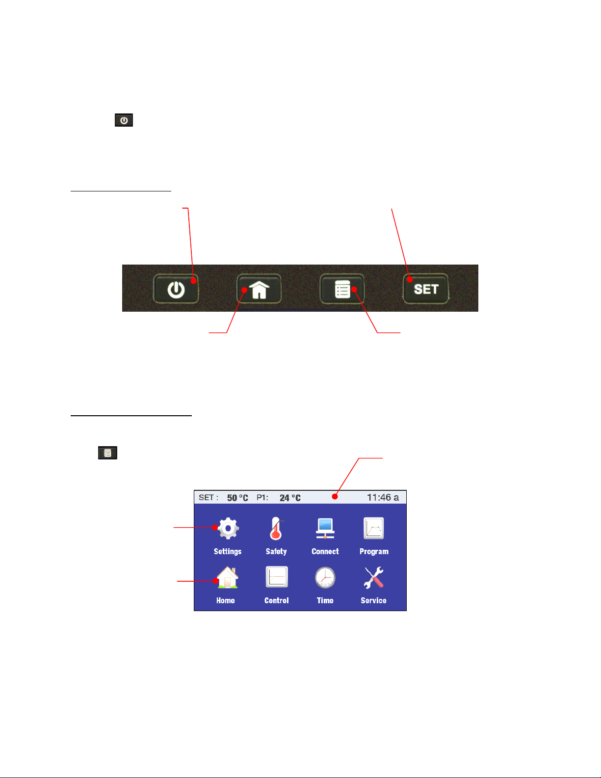
Controls & Components
Performance Digital Controller
SmartTouch™ Touch
Screen Display
Power Key
Home Key
Menu Key
Set Key
Swivel 180™
Latch Release
Power Switch /
Circuit Breaker
(located on Refrigeration
Power Module on
Refrigerating/Heating
Circulators)
Safety Set
Thermostat
IEC Electrical
Connection
IEC Power Cord
Fluid Inlet
Connection
Inert Gas Injection Port
USB A Connection
USB B Connection
Ethernet Connection
RS232/RS485
Serial Port
External (P2)
Temperature Probe
Connection
Refrigeration Control
Connection (functional on
Refrigerating/Heating
Circulators only)
Fluid Outlet Connection
Bypass Tubing
110-515 PSC/EN
9
Page 11
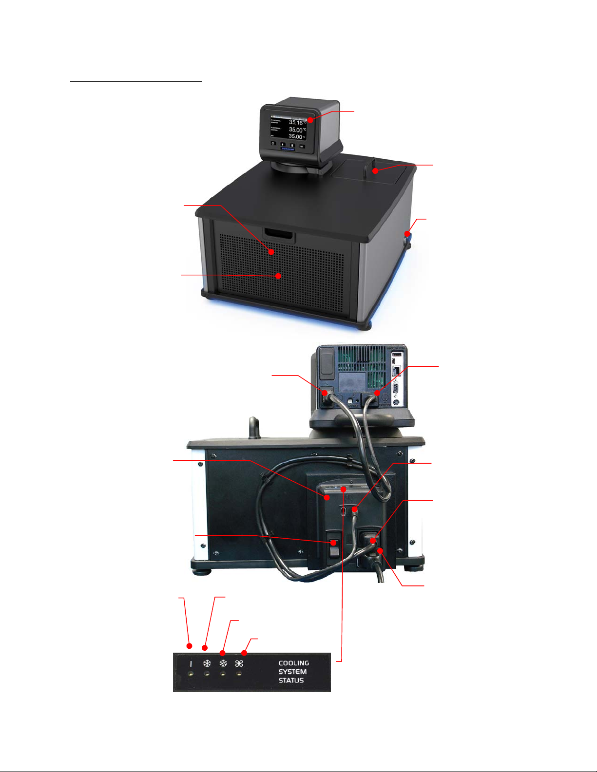
Refrigerating/Heating Baths
Performance Digital Temperature
Controller
Reservoir Cover
Reservoir Drain Valve and Port
(behind access panel)
Side access on AP7LR-20)
Washable Air Filter
(behind access panel)
Refrigeration Power
Module
IEC Power Connection to
Refrigeration Module
Drain Valve and Port
(right side on AP7LR-20 only)
Refrigeration
Control Connection
Refrigeration Control
Connection
IEC Power Connection
to Controller
Power Switch / Circuit Breaker
IEC Electrical Connection
Power
Cooling
Cooling Fault
Fan
to Mains
Cooling System Status Display
110-515 PSC/EN
10
Page 12
Heating Only Baths
Reservoir Drain and Port
(behind access panel)
Performance Digital Controller
Reservoir Cover
Power Switch / Circuit Breaker
IEC Power Connection to
Mains
Tap Water Cooling
Connection (inlet)
Tap Water Cooling
Connection (outlet)
WARNING: To avoid the potential for burns, allow the Circulator to cool completely before cleaning
or performing any maintenance.
110-515 PSC/EN
11
Page 13
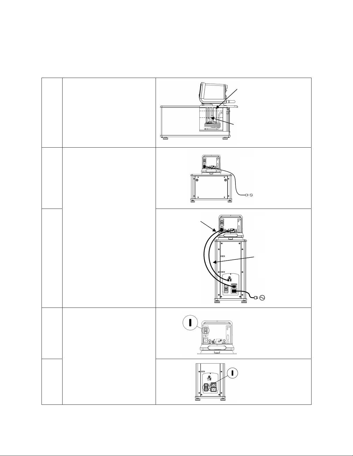
Quick-Start
Unless otherwise specified, quick-start instructions apply to all models.
See Installation & Startup for additional information.
Maximum: 1 in. / 2.54 cm
below underside of top deck
1 Fill reservoir with fluid
2A
Connect all electrical power cords
and control cables
2B
Minimum: 3.0 in. / 7.6 cm
below underside of top deck
Heating only models
IEC power cord
from Controller
to Refrigeration
Power Module
Refrigerating / Heating
models
Refrigeration control
cable
Heating only models
3A
Place Power Switch / Circuit
Breaker in ON position
Refrigerating / Heating
models
3B
110-515 PSC/EN
12
Page 14
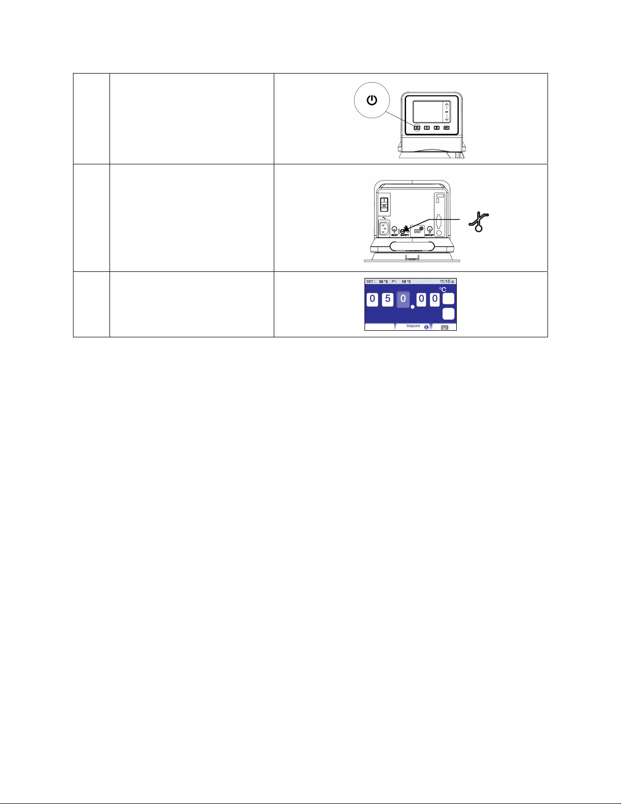
4 Turn Controller “ON”
5 Set safety thermostat
6 Set Temperature Set Point
Installation & Startup
Your Circulating Bath with Performance Digital Temperature Controller is designed to be simple to set-up
and install. The only tools required are a Philips-head screwdriver and a container for adding water or
other suitable fluid to the bath reservoir.
General Site Requirements
Locate your Circulator on a level surface free from drafts and direct sunlight. Do not place it where there
are corrosive fumes, excessive moisture, high room temperatures, or in excessively dusty areas.
Refrigerating / Heating Circulators must be 10.2 cm / 4 inches or more away from walls or vertical
surfaces so that airflow is not restricted.
Avoid voltage drops by using properly grounded power outlets wired with 14 gauge or larger diameter
wire and if possible, be close to the power distribution panel. The use of extension cords is not
recommended; this will reduce the potential for problems caused by low line voltage.
110-515 PSC/EN
13
Page 15
Adding Liquid to the Bath Reservoir
WARNING: When using Class III flammable fluids per DIN 12876-1, the user must attach the
following warning labels to the front of the unit so that they are well visible:
Warning Label
W09
Colors: Yellow/black
Mandatory Label
M018
Colors: Blue/white
or
Semi S1-0701
Table A1-2 #9
Colors: Blue/white
WARNING: Read the safety data sheet for the bath fluid being used carefully before filling reservoir.
WARNING: See Technical Information in the rear of this manual for a list of compatible liquids.
WARNING: If the proper fluid level is not maintained, the heater coil may become exposed and
possibly damaged (fluid level too low) or the bath may overflow (fluid level too high).
Danger Area.
Attention! Observe instructions
(operating manual, safety data sheet)
Carefully read the user information prior to
beginning operation.
Scope: EU
Carefully read the user information prior to
beginning operation.
Scope: NAFTA
The liquid in the reservoir should be maintained at a depth between 1 inch / 2.54 cm and 3.0 inches / 7.6
cm below the underside of the bath’s top deck. Upon start up, it may be necessary to add fluid to the bath
to compensate for the fluid required for external circulation. Likewise, be sure to compensate for fluid
displacement when placing samples or other materials in the Circulator’s reservoir.
Maximum Fluid Level =
1 inch / 2.54 cm below
underside of top deck
Minimum Fluid Level =
3.0 inches / 7.6 cm
below underside of top
deck
WARNING: Always drain all fluid from the reservoir before moving or lifting your Circulator. Be sure
to follow your organization’s procedures and practices regarding the safe lifting and relocation of
heavy objects.
WARNING: To avoid the potential for burns, allow the Circulator to cool completely before cleaning
or performing any maintenance.
110-515 PSC/EN
14
Page 16
Pump Inlet and Outlet Connections
WARNING: When connecting tubing to an external application, it is the user’s responsibility to make
sure that the tubing and fittings connected to the Circulator are suitable for the fluid being used and
the temperature range of operation.
CAUTION: The Circulator’s bypass tubing is secured to the fluid inlet and outlet connections by high
temperature nylon hose clamps, which can be removed by carefully cutting them with diagonal
cutters.
CAUTION: Secure the tubing to the inlet and outlet fittings using hose clamps with a minimum ID of
7/8 inch (22 mm). Do not operate the unit without hose clamps.
WARNING: If the Circulating Bath will not be used for external circulation, the inlet and outlet ports
should remain connected using the Buna N bypass tubing provided with the unit.
The pump inlet and outlet ports are female ¼ inch NPT connections that permit use of barbed tubing
adapters or hard plumbing fittings. ½ inch (13mm) ID tubing may also be slid over these connections and
held in place with a hose clamp.
If the pump inlet and outlet are not used for external circulation, the Bypass Tubing provided with the unit
should be left in place in order to optimize fluid mixing within the reservoir.
The nylon barbed tubing adapter fittings supplied with the unit are intended for applications from
-40° to 93°C. For applications above 93°C, brass, stainless steel, or Teflon
®
fittings are recommended. ¼
inch NPT to M16 stainless steel male adapter fittings are provided with all 50Hz models.
NOTE: The use of quick-connect fittings is not recommended as they typically restrict flow rate.
External Closed Loop Circulation
Connect the pump inlet and outlet to the external apparatus. To maintain adequate flow, avoid restrictions
in the tubing. When connecting the Circulator to more than two closed loops, the use of a manifold made
of “Y” adapters to divide the fluid into multiple banks is recommended. After setting up multiple closed
loops, check for adequate flow at the return manifold of each loop and check that the bath fluid is at an
adequate level. A booster pump may be added to closed loops without damaging the Circulator’s pump.
The temperature control stability of a closed loop system is better at the external apparatus than in the
Circulator reservoir (provided the control point of the apparatus represents a constant load and is well
insulated). For example, if you circulate fluid through a viscometer at 50°C, the temperature variation
observed in the Circulator reservoir may be ±0.1°C while the temperature variation in the viscometer may
be only ±0.05°C.
Although temperature stability is generally better at the external apparatus control point, depending on the
length of tubing used and the efficiency of the insulation, the actual temperature reading at the external
apparatus may be slightly different than the temperature reading at the Circulator reservoir.
110-515 PSC/EN
15
Page 17
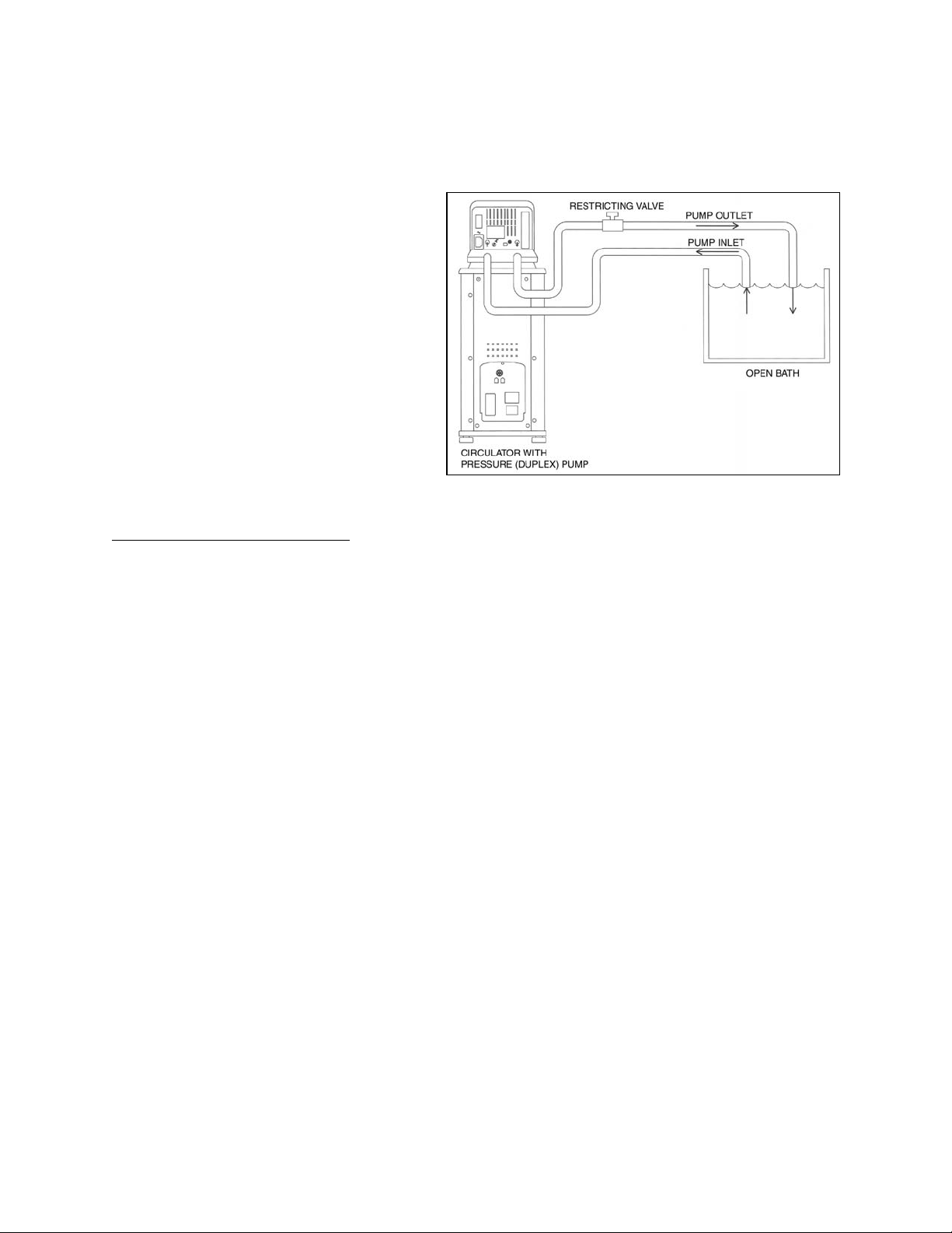
Open Loop Circulation
The duplex (pressure/suction) pump permits circulation to and from an external open bath. To prevent
siphoning when the Circulating Bath is turned off, position both baths so that the two fluid levels are at the
same elevation.
Connect the pump inlet and outlet to the
external bath using tubing of the same
diameter and length. The same size fittings
should also be used on both the inlet (suction)
and outlet (pressure). This helps ensure a
balanced flow. A restricting valve or pinch clip
should be installed in the pressure (outlet)
tubing and adjusted to match the return
suction (inlet) flow rate. Cut the external end
of the suction tube into a “V” shape so that the
tube will not seal itself against the wall of the
external tank. Both the pressure and suction
tubing should be securely fastened to the
external tank to prevent movement during
use.
When using flexible tubing, the suction tubing must have a wall thickness that will not collapse under
vacuum, particularly when going around bends.
Circulating Bath Height Regulation
— Position the ends of the pressure and suction tubes at the desired
maximum fluid level in the external bath and fill the bath to that level. Fill the Circulating Bath to a height
one inch (25mm) below the top of the reservoir. Start the pump and adjust the restricting valve/pinch clip
on the outlet tubing until the liquid height in both baths remains constant. Add fluid to the baths as needed
to compensate for the fluid in the inlet and outlet lines.
110-515 PSC/EN
16
Page 18
Refrigeration Control Connections (Refrigerating/Heating Circulators only)
Refrigeration Control
Connection
Refrigeration Control
Cable
Refrigeration Control
Connection
Electrical Power
WARNING: The Circulator’s power cord must be connected to a properly grounded electrical
receptacle. Make certain that this electrical outlet is the same voltage and frequency as your
Circulator. The correct voltage and frequency for your Circulator are indicated on the identification
label on the back of the Controller.
CAUTION: The use of an extension cord is not recommended. If one is necessary, it must be
properly grounded and capable of handling the total wattage of the unit. The extension cord must not
cause more than a 10% drop in voltage to the unit.
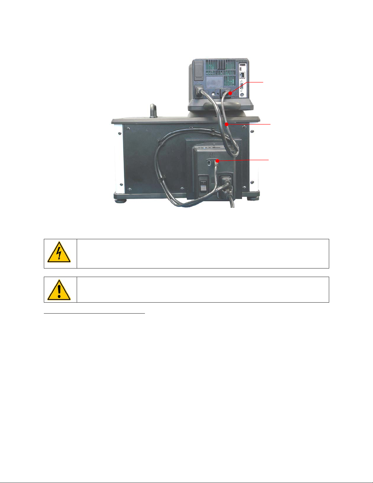
Refrigerating / Heating Circulators
Attach the 3-ft / 0.91 m power cord to the IEC electrical connectors on the Temperature Controller (male)
and the Refrigeration Power Module (female).
Attach the 6-ft / 1.8 m power cord to the IEC electrical connection on the Refrigeration Power Module and
then plug the male connector into the Mains electrical outlet.
Place the Power Switch / Circuit Breaker on the Refrigeration Power Module in the ON position. An hour
glass will appear on the Temperature Controller’s display while the Circulator completes an initialization
sequence. Once completed, “Standby” will appear on the display; the Power Key will also light.
110-515 PSC/EN
17
Page 19
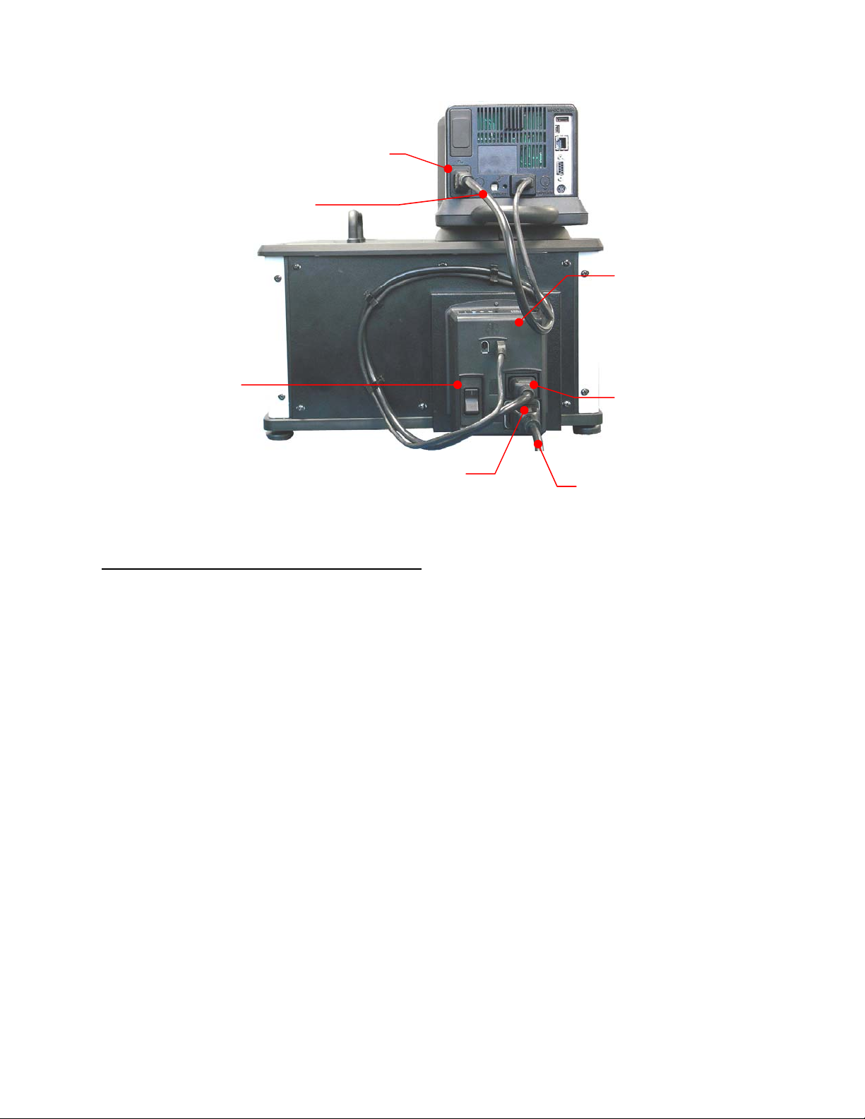
IEC Power Connection to
Refrigeration Power Module
IEC to IEC Power Cord
Refrigeration
Power Module
Power Switch /
Circuit Breaker
IEC Power
Connection to
Controller
IEC Power Connection to Mains
IEC to Mains Power Cord
Heat Only Circulators and Open Bath Systems
Attach the 6-ft / 1.8 m power cord to the IEC electrical connection on the Temperature Controller and then
plug the male connector into the Mains electrical outlet.
Place the Power Switch / Circuit Breaker on the Temperature Controller in the ON position. The display
on the Controller will light and “Standby” will appear on the display; the Power Key will also light.
110-515 PSC/EN
18
Page 20
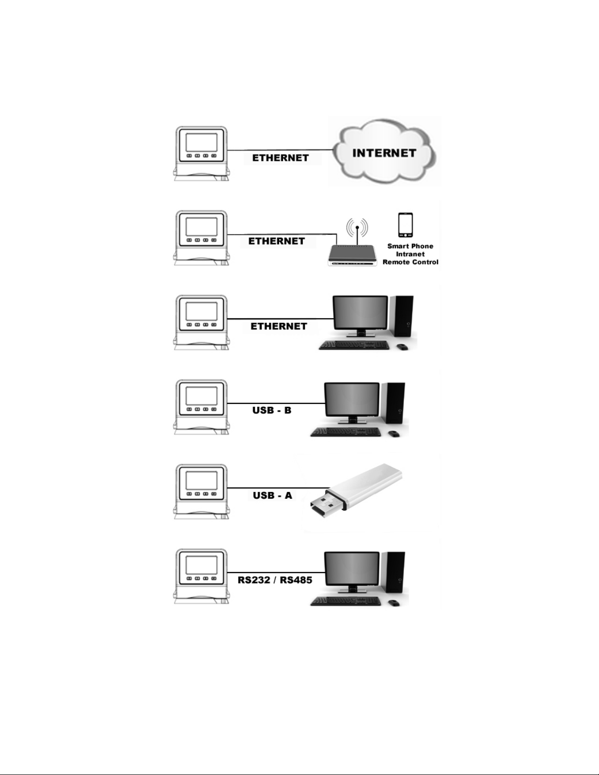
Communication
The Performance Digital Controller features a variety of connectivity options. Following are some typical
ways you can use them to monitor and control the operation of your Circulator.
110-515 PSC/EN
19
Page 21
USB Communication
Two USB ports (A and B) are provided on the rear of the Temperature Controller for use with USB flash
drives to log temperature data and store and/or transfer time/temperature programs. See Basic
Operation, Communications and Data Logging for more information.
Ethernet
An Ethernet port is provided on the back of the Temperature Controller to enable you to connect your
Circulator to a computer network.
RS232 / RS485 Serial Communication
CAUTION: Always turn electrical power to the Circulator OFF before making a connection to the
serial (DB9) port.
Your Circulator features RS232 / RS485 serial communication for remote data logging and control
capability. A DB9 connector is provided on the rear of the Temperature Controller for this purpose. See
Basic Operation, Communications and Data Logging for set up information.
The serial interface should be connected to a serial communication port on a remote PC using an
appropriate cable. Information on the RS232 / RS485 commands and communication protocol can be
found in the Technical Information section of this manual.
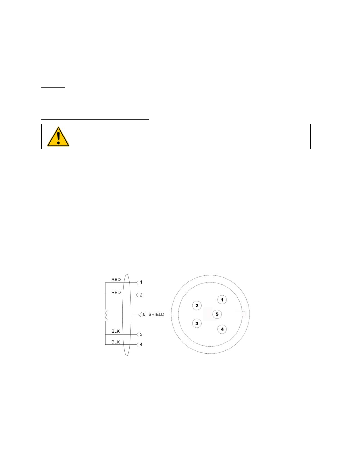
External (P2) Temperature Probe
Your Circulator is capable of controlling temperature based on either the temperature of the internal bath
or that of an external vessel or device. The connection for the optional external temperature probe is on
the rear of the Temperature Controller. The Temperature Controller automatically detects the external
temperature probe when it is connected. See Replacement Parts & Accessories for available lengths and
part numbers.
Pin Out Diagrams — External (P2) Temperature Probe Connection
MAXIMUM OPERATING TEMPERATURE @ 200 C, CLASS A 0.003850 OHMS/DEGREES C.
RTD SENSOR: 4 WIRE CIRCUIT, 100 OHMS @ 0 DEGREES C,
110-515 PSC/EN
20
Page 22
Controller Setup
Power
Press . “Initializing” will appear briefly on the display, the Circulator will begin running, and the default
Main Run screen will appear.
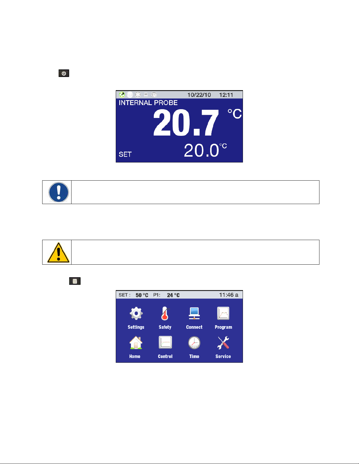
Safety Set Temperature
NOTE: The Safety Set Temperature is displayed and set in whichever temperature unit is currently
selected. The default is °C. To set the temperature using °F, see General Operational Settings, Unit.
This is a “Do Not Exceed” temperature setting for your Circulator and is the temperature at which the
heater will be turned OFF should the liquid level in the bath drop too low or the heater malfunctions. It is
normally set about 5° higher than the desired operating temperature. Setting the Safety Set Temperature
is a simple 4-step procedure.
WARNING: The Safety Thermostat is user-adjustable from approximately 40° to 240°C / 104° to 464°F.
Do not force the indicator dial beyond the stops at either end of the dial’s range.
1. Press to access the Main menu.
2. Touch the Safety icon to access the Safety sub-menu.
110-515 PSC/EN
21
Page 23
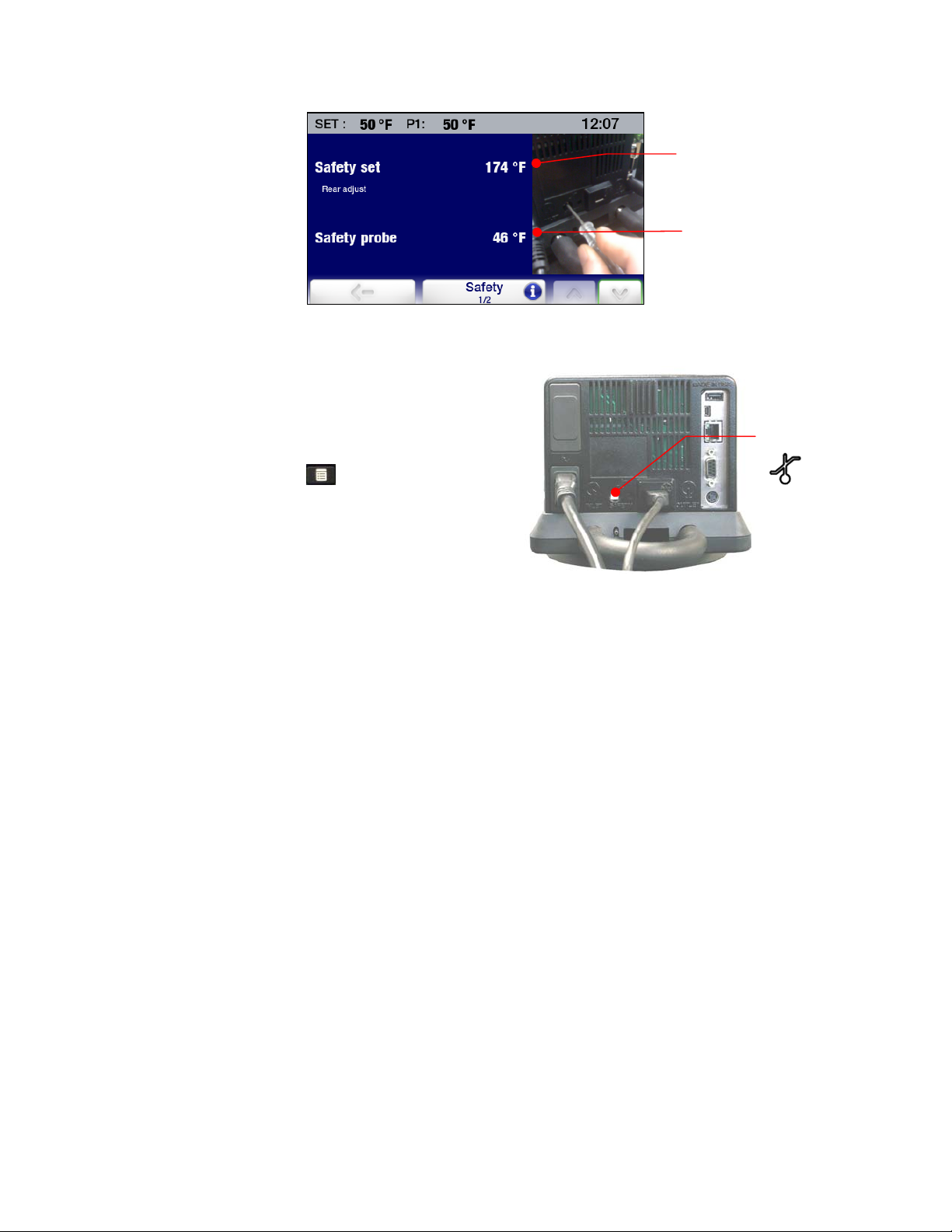
3. Using a small, Philips head screwdriver, rotate the
Safety Set Thermostat on the rear of the
Temperature Controller until the desired Safety Set
Temperature is displayed (clockwise to increase;
counter-clockwise to decrease).
4. Press the icon or the
Main Menu.
key to return to the
Safety Set
Temperature
Current Safety Probe
reading
Safety Set
Thermostat
110-515 PSC/EN
22
Page 24
Basic Operation
Turning Your Circulator On
Press the key.
The Circulator will begin running and the Main Operational Display (Home) will appear.
Controller & Touch Screen Navigation
Controller Navigation
Turns the Circulator’s
Temperature Controller ON
POWER –
and OFF.
Returns the to the Main Operational
Display (Home) from any screen
Toggles through available
HOME --
Home screens.
Touch Screen Navigation
Main Menu
Press to access.
Used in conjunction with various screen
icons and buttons to change the set point
SET --
temperature
MENU --
Accesses the Temperature
Controller’s Main Menu (from any
screen)
Status Bar – Appears on all screens
Accesses associated
screen (Home screen)
sub-menu
Return to Main Run
110-515 PSC/EN
23
Page 25
Sub-Menus
NOTE: The following examples are intended to illustrate how commonly used touch screen icons
function when displayed. A specific icon may or may not be displayed on a sub-menu page. The
function/operation of icons not shown here are described in the sections associated with the screens
on which they appear.
Sub-Menu Item --
Toggles between
available choices
Previous Menu
Cancel -- Cancels
change to a setting
Help regarding sub-menu items
Information –
Current Setting (white
letters on blue field)
Alternate Setting
(blue letters on white
field)
Previous Page
Next Page
Decreases Value
Increases Value
Accept --
Accepts change to
a setting
CAUTION: The menu and sub-menu screens time-out and revert to the Main Operational Display
(Home Screen) after approximately 30 seconds without any touch screen interaction. Any changes
made will take effect automatically.
Current Setting (more than two
settings available) – Touch to access
other available selections
110-515 PSC/EN
24
Page 26

Menu Structure
Sub-Menu Item Description / Selections
Pump Speed
Unit
Sound
Language
Settings
Safety
Connect
Program P1 Create, edit, run, and save an event.
Control
Time
Service
Display
Lock Out
Auto Restart
Personalize
Display Filter
SHC
Safety Set
Safety Probe
High Limit
Low Limit
High Alarm
Low Alarm
Ethernet
RS232
USB
RS485 Address
Probe Control
Auto Cool
Fluid Type
P2 – P1
PID
External Cooling Control
Send Internal Data USB/Web
Reset memory and reboot
Timer
Time
Date
Schedule
Air Filter Service Interval
Fluid Service Interval
Clear Pump Operation
Clear Cooling Operation
Calibration
Installation Operation
Display Module Firmware
Powerboard Module Firmware
Cooling Module Firmware
5% to 100%
°C / °F
On / Off
Available display languages
Temperature display resolution: .XX / .XXX
Yes / No
Yes / No
Off / PNG
Display averaging: 1 to 7 seconds
Specific heat capacity unit: BTU/(LB.°F) / kJ(kg/°C)
Displays current safety set temperature
Displays current safety probe temperature
202°C maximum / 25°C minimum
-72°C minimum / 20°C maximum
202°C maximum / 25°C minimum
-72°C minimum / 20°C maximum
Ethernet connection
1200 to 115,200 baud
Logging On / Off
Addressable
P1 (internal) / P2 (external)
Set temperature at which refrigeration activates: 2° to 152°C
Optimizes operation for a specific fluid type
Maximum allowable temperature differential between P1 and P2
User / Factory
Operating parameters for optional external cooling valve
Outputs diagnostic file
Resets unit to factory defaults
0 to 999 minutes
Time and time format
Year, Month, Day
Set time and date to auto-start a program
Time remaining until air filter cleaning
Time remaining until fluid replacement
Reset / display number of days pump has been operating
Reset / display number of days compressor has been operating
Calibration table entry
Number of days unit has been operating
Version
Version
Version
110-515 PSC/EN
25
Page 27

Main Operational Displays (Home Screens)
Your Circulator features seven Main Operational Displays (Home screens). You can see the available
choices and select a specific Home screen by pressing the
Status Bar
A status bar displaying important operating information is displayed at the top of every Home and Menu
screen. The information included on the status bar is determined by the type of screen on which it
appears.
Home Screen Status Bar
key.
Heater Status (ON when lit)
Circulating Status
(ON when lit)
Lit when data logging
Menu and Sub-Menu Screens Status Bar
Set point temperature
Refrigeration Status (ON when lit)
Lit when an event program is scheduled to run
Date and time
Actual temperature
(P1 = Internal Control; P-2 = External Control
Time
110-515 PSC/EN
26
Page 28

Home Screens
Primary Home Screens
Temperature Probe
controlling fluid
temperature
Internal or External
The background for this style Home screen may be either blue or black.
NOTE: On primary home screens, the actual and set point temperatures are displayed to one decimal
point resolution only, regardless of the resolution selected in the Settings / Display sub-menu.
Temperature Detail Home Screens
Actual bath
temperature
Set point
temperature
Temperature probe controlling
Temperature probe monitoring
fluid temperature
P1 = Internal
P2 = External
fluid temperature
P1 = Internal
P2 = External
The background for this style Home screen may be either blue or black.
Temperature Trend Home Screen
P1 Internal temperature
reading
P2 External temperature
reading or status
Set point temperature
Press highlighted button to add associated line to
temperature trend graph
Actual bath temperature
Shown to either two or three
decimal points
Set point temperature
Shown to two decimal points
Temperature Trend graph
Scales from 4 minutes to 10
days
Scale currently in use for
temperature trend graph. Press
to change.
The background for this style Home screen is blue only.
Temperature trend line keys:
Black = P1 temperature; Blue = P2 temperature
Green = Set point temperature
Red: = High and Low Alarm settings
110-515 PSC/EN
27
Page 29

Personalized Home Screen
Actual bath
temperature
P1 = Internal
P2 = External
Set point
temperature
Adjusting the Temperature Set Point
This is the temperature at which the fluid in your Circulating Bath will be maintained. It may be set to one
one-hundredth of a degree over a range of -50.00° to +200.00°C / -58.00° to +392.000°F. The factory
default set point is +20.00°C / +68.00°C.
NOTE: Although temperature can be displayed with three decimal point resolution, set point
temperatures may only be set to two decimal points.
Custom image or text
To optimize operational flexibility, set point temperature changes can be initiated in several ways.
Controller Keypad
Press this key when any
Home screen or the
Main Menu screen is
displayed
NOTE: To change the temperature set point while operating in the Temperature Trend Home screen,
you must press the SET key on the Controller’s front panel. Temperature set point cannot be changed
while a program is running.
110-515 PSC/EN
28
Page 30

Primary Home Screen Temperature Detail Home Screen
Touch SET or numerical set
point value
Touch numerical set point
value
Personalized Home Screen
Touch highlighted area
Entering the Set Point Temperature Value
Once a temperature set point change has been initiated by pressing the
the display, the set point entry screen will appear.
Touch individual number field
to make changes to that field
Once 9 appears in the field, it
will roll to 0 and the field to its
left will increment one
number.
key or appropriate area on
Increases displayed
value
Decreases displayed
value
Touch to enter values using the
numeric keypad (shown on next page)
110-515 PSC/EN
29
Page 31

Displays entered
value
Inputs numerical value
Toggles minus sign
ON and OFF
Clears last number entered
Accepts change
Cancels change
Accepts change
Cancels change
CAUTION: The menu and sub-menu screens time-out and revert to the Main Operational Display
(Home Screen) if approximately 30 seconds pass without any touch screen interaction. Any changes
made will take effect automatically.
General Operational Settings
The Settings sub-menu is used to select the Temperature Controller’s general operational characteristics.
Press
to access the Main menu.
Touch the Settings icon to access the Settings sub-menus.
110-515 PSC/EN
30
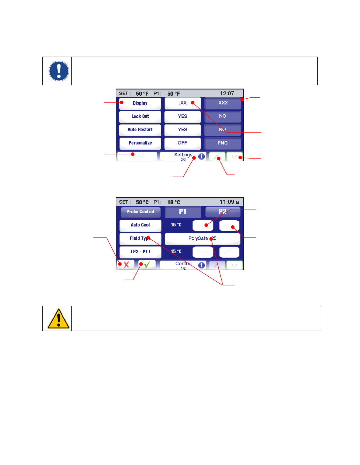
Page 32

Settings – Page 1 Settings – Page 2 Settings – Page 3
Pump Speed — Sets pump speed. The current setting is displayed between the < (decrease) and >
(increase) icons and is adjustable from 5% to 100%. Touch to accept the new value, to cancel.
Unit — Sets the unit in which temperature will be displayed. The current setting is shown in the nonhighlighted (blue) field. To change, touch Unit icon or the ° icon in the highlighted (white) field. Touch to
accept the new temperature unit, to cancel.
Sound — Turns sound ON and OFF. The current setting is shown in the non-highlighted (blue) field. To
change, touch the Sound icon or the icon in the highlighted (white) field. Touch to accept, to cancel.
Language — Sets the language in which all menus will be displayed.
The current selection is shown to the right of the Language icon. To
change, touch either the left or right highlighted (white) Language field.
A screen showing the available languages will appear:
The current setting is shown in the non-highlighted (blue) field. To
change, touch the icon associated with the desired language. Touch
to return to the Settings sub-menu.
Touch to advance to page 2 in the Settings sub-menu.
Display — Sets the number of decimal points in which actual and set point temperature will be displayed.
The current setting is shown in the non-highlighted (blue) field. To change, touch the Display icon or the
icon in the highlighted (white) field. Touch to accept, to cancel;
NOTE: Temperature is shown to one decimal point only on the Primary (largest) display, regardless of
the display setting. See Main Operational Displays (Home Screens) for more information.
Lock Out — Allows you to block temperature set point and other changes. While this feature is activated,
the unit will remain running at the current settings. See Basic Operation, Enabling/Disabling the Local
Lock Out for information on using this feature.
Auto Restart — This determines how the unit will begin operating after a disruption to electrical power.
When YES is selected, the Circulator will begin running automatically when power is restored. When NO
is selected, the Circulator will power up in the Standby mode. A message will also be displayed to alert
you to the power outage. The current setting is shown in the non-highlighted (blue) field. To change,
touch the Auto Restart icon or the icon in the highlighted (white) field. Touch to accept the new setting,
to cancel.
WARNING: The unit may start automatically after a disruption in electrical power.
Personalize — Allows the personalization of one of the Home screens with an image or text. See
Creating and Installing a Personalized Home Screen for information on adding text/images.
Touch to advance to page 3 in the Settings sub-menu.
110-515 PSC/EN
31
Page 33

Display Filter —This setting determines the averaging time used when displaying temperature
information. Higher settings will generally result in less fluctuation, while lower settings will more
accurately reflect real-time temperature probe data. Use the < (decrease) and > (increase) icons to
change the current setting; touch to accept the new value, to cancel.
SHC (Specific Heat Capacity)— Sets the unit (BTU or kJ) in which Specific Heat Capacity will be
displayed. Works in conjunction with the Fluid Type setting in the Control sub-menu. To change, touch
the SHC icon or the icon in the highlighted (white) field. Touch to accept the new setting, to cancel.
Time and Date Settings
Touch the Time icon on the Main Menu; the Time sub-menu will be displayed.
Time — Sets the time in either 12 or 24 hour format. To change, touch the Time icon or the actual
displayed time. Depending on the actual time and current time format, one of the following screens will
appear:
To change the time format, touch the 12H or 24H. Touch to accept the new setting, to cancel.
To change the time, touch the up/down arrow icons associated with the hours or minutes. You can also
change the hour or minutes setting by touching the number itself; this will bring up a numeric keypad on
which the correct hour or minute can be entered. Touch
Date — Sets the date in Year/Month/Day format. To change, touch the Date icon or the actual displayed
date; the following screen will appear:
12 hour format – AM 12 hour format – PM 24 hour format
to accept the new setting,
to cancel.
Month
Year
Day
110-515 PSC/EN
32
Page 34

To change the current setting, press the appropriate Year, Month, or Day icon and then touch < or >. You
can also change the Day by simply pressing the appropriate date on the calendar. Touch
new setting,
to cancel.
NOTE: See Basic Operation, Timer and Advanced Operation, Event Scheduling for information on the
Timer and Schedule functions.
Safety Settings
Touch the Safety icon on the Main Menu. The following screen will appear:
Displays the current
safety probe reading.
Touch to advance to the next page in the Safety sub-menu.
to accept the
Current safety set
temperature.
See Controller Setup for
information on changing
this value
Highest allowable set point
Lowest allowable set point
Temperature above which
unit will automatically shut
Temperature below which
unit will automatically shut
temperature
temperature
down
down
Current setting; touch
number to access
numeric keypad
High Limit / Low Limit Temperatures — These values establish limits on how high or low the
temperature set point may be set. To change, touch the up/down arrow icons. You can also change limit
value by touching the number itself; this will bring up a numeric keypad on which the desired limit
temperature can be entered. Touch
to accept the new setting,
to cancel.
High Alarm / Low Alarm Temperatures — These values establish the maximum allowable temperature
range for the unit. If the fluid temperature goes outside of this range, the system will shutdown. To
change, touch the up/down arrow icons. You can also change limit value by touching the number itself;
this will bring up a numeric keypad on which the desired limit temperature can be entered. Touch
accept the new setting,
to cancel.
to
110-515 PSC/EN
33
Page 35
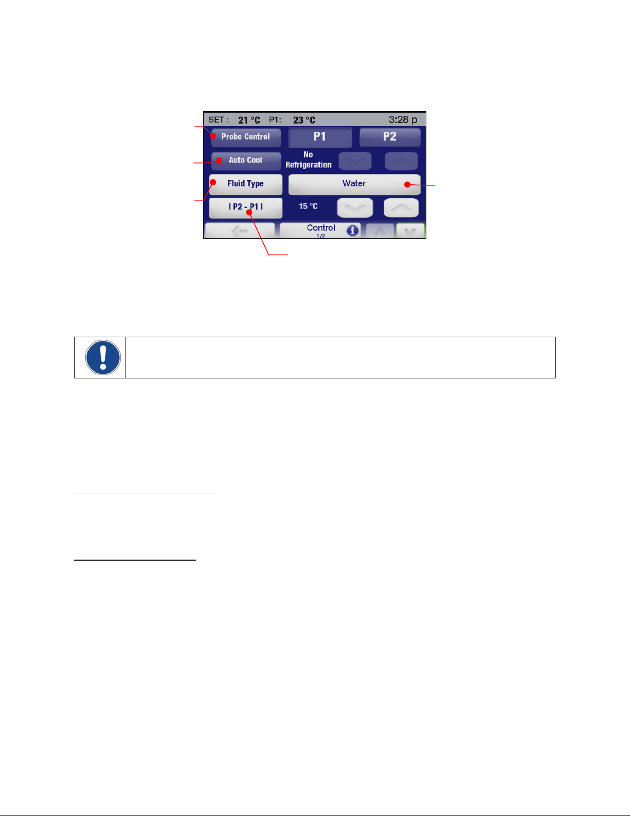
Control
Touch the Control icon on the Main Menu. Page 1 of the Control sub-menu will appear:
Selects internal (P1) or
external (P2) temperature
The temperature at which
refrigeration will be initiated
Optimizes temperature
control based on a fluid’s
specific heat capacity
Probe Control — This establishes whether temperature control will be based on the fluid temperature
within the Circulator’s reservoir or the fluid temperature at an external device. Touch the P1 icon to select
internal control; touch the P2 icon to select external control. Touch
cancel.
control
Current bath fluid selection
Sets maximum allowable differential between the
measured internal and external temperatures
to accept the new setting,
to
NOTE: P2 can only be selected when a remote temperature probe is connected to the Temperature
Controller.
Auto Cool — This control setting functions only on refrigerated circulators. The setting determines the
bath temperature at which refrigeration will be activated, permits more precise control when operating at
high temperatures as well as more rapid cool downs. For most applications, a set point that is 15C above
room temperature is recommended. The Auto-Cool control range is from +2C to 152C.
To change, touch the up/down arrow icons. You can also change the auto cool temperature by touching
the number itself; this will bring up a numeric keypad on which the desired value can be entered. Touch
to accept the new setting,
Cool Command™ Refrigeration
to cancel.
— -40°C 7 liter Refrigerating/Heating Circulators and 15 liter and larger
Refrigerating/Heating Circulators feature the Cool Command™ modulating refrigeration control system.
Cool Command allows the refrigeration system to turn on at a fluid temperature up to 152C when the
temperature set point is changed to or below the Auto-Refrigeration set point (152°C maximum). As a
result, bath fluid cools more quickly.
Conventional Refrigeration
— -20°C 7 liter Refrigerating/Heating Circulators use a conventional
refrigeration system. The refrigeration system will turn on when the bath fluid temperature and set point
are below the Auto-Refrigeration set point (85°C maximum).
110-515 PSC/EN
34
Page 36

Fluid Type — This sets the specific heat capacity (SHC) for the bath fluid being used to achieve optimal
temperature control. Touch the Fluid Type or Current Bath Fluid icon to access a list of fluids; select
custom from the list to manually enter the SHC. Touch
to accept the new setting,
Fluid list
SHC of selected
fluid
Select to manually enter SHC
I P2 – P1 I — This setting is for use when external temperature control (P2) is being used. It establishes
the maximum allowable differential between the external and internal measured temperatures and is
intended to prevent uncontrolled heating or cooling should the external temperature probe be dislodged
or fail. To change, touch the up/down arrow icons. You can also change displayed value by touching the
number itself; this will bring up a numeric keypad on which the desired differential temperature can be
entered. Touch
to accept the new setting,
to cancel.
to cancel.
Touch to advance to page 2 in the Control sub-menu.
Selects PID
Selects External
Cooling Control
Outputs diagnostic
data file
Restores all Factory
Default settings
Selects manual
PID entry
PID — This determines whether Factory or User-set PID settings will be used for temperature control. To
manually enter PID value, touch the User icon and then use the increase and decrease icons to adjust
the Proportional (P), Integral (I), and Derivative (D) settings until to the desired values. Touch
the new settings,
Manual PID entry screen
to cancel.
Restores user-set PID
settings to original
Factory values
to accept
110-515 PSC/EN
35
Page 37

CAUTION: The Performance Digital Temperature Controller’s factory PID settings have been adjusted
to achieve optimum temperature control. User-set PID values should only be used by individuals with a
thorough knowledge and understanding of Proportional/Integral/Derivative control.
External Cooling Control — This feature is only functional on units fitted with the optional External
Cooling solenoid valve. See External Cooling Control in the Technical Information section of this manual
for more information.
Send Internal Data USB/WEB — This sends a diagnostic file to either a connected flash drive or web
monitoring page. See Diagnostic Data Logging in the Routine Maintenance & Troubleshooting section of
this manual for more information.
Reset Memory and Reboot — Restores Temperature Controller to all Factory default settings and
values. See Restoring All Factory Default Values.
Communications and Data Logging
Touch the Connect icon on the Main Menu. The following screen will appear:
Configures Ethernet
Sets RS485 address
via numeric keypad
connection
Selects emulation
mode for RS232
communications
Turns data logging ON and
OFF
Ethernet — The Performance Digital Controller may be connected directly to a laptop or desktop
computer via its Ethernet connection or indirectly via your facility’s wired or wireless network. Either type
of connection enables you to control and/or monitor the operation of your circulating bath in real time
using an Internet browser by entering its IP address. The Controller’s active serial communications
commands are used to retrieve and/or change operational information. The Ethernet selection in the
Connect sub-menu allows you to configure the IP address and subnet mask. When touched, the following
screen is displayed:
Allows manual entry of IP
address via numeric
keypad
Sets TCP password via alpha-
Selects dynamic
entry of IP address
When DHCP is selected, the following screen appears. It displays the dynamically assigned IP address.
numeric keypad
Turns TCP Control password
protection ON and OFF
Displays dynamically
assigned IP address
Selects manual
entry of IP address
110-515 PSC/EN
36
Page 38

NOTE: See the Technical Information section for information regarding Ethernet configuration. See
the Advanced Operation section for information on monitoring/controlling your Circulator using an
internet browser.
RS232 — This is used to set the baud rate for RS232 bi-directional communications and, if desired, a
communications protocol that emulates other common circulating baths. The increase and decrease
icons are used to adjust the baud rate; you can also increase the baud rate by touching the displayed
numerical value. Touch
To select an RS232 communications protocol that emulates another circulator, touch the RS232 icon; the
following screen will appear:
Touch the icon that represents the represents Read (or Get) Temperature command for the device.
Touch
to accept the new settings,
USB — The Performance Digital Temperature Controller has both USB A and USB B ports. The USB A
port is used for data logging; data is stored in a CSV file that can be read by spreadsheet programs such
as Microsoft Excel
®
. To begin data logging, plug a flash drive into the USB A port and then touch the
Logging icon to turn logging ON. Touch
to accept the new settings,
to cancel.
to accept,
to cancel.
to cancel.
NOTE: See the Technical Information for complete information regarding data logging file formats
and content.
The USB B port can be used to monitor or control your Circulator using a personal computer. See the
Technical Information section of this manual for more information.
RS485 — This is used to set the address for RS485 communications. The Temperature Controller
supports cable lengths up to 1000 ft / 304.8 m. Use the increase and decrease icons to enter the desired
RS485 address. You can also enter the address by touching the RS485 icon; this will bring up a numeric
keypad on which the address can be entered. Touch
to accept the entered address,
to cancel.
110-515 PSC/EN
37
Page 39

Timer
Touch the Time icon on the Main Menu. The Time sub-menu will be displayed.
Starts and stops timer
Accesses numeric
keypad
The Timer may be set from 0 to 999 minutes in one minute increments. Use the increase and decrease
icons to change the displayed time or touch the Minutes icon to access a numeric keypad on which the
desired interval can be entered.
To start the timer, touch the Timer icon. A clock icon and digital counter counting down the time (in
minutes and seconds) will be displayed in the right corner of the status bar. Once it reaches 0:00, digital
counter will turn red and begin counting up so you know how much time has elapsed since the end of the
timed event.
Displays remaining time in black;
Displays elapsed time from end
of event in red
To stop or reset the timer, touch the Timer icon.
NOTE: See Time and Date Settings for information on selecting the time format (12 or 24 hour) and
changing the time and date settings; see Advanced Operation for information on Event Scheduling.
110-515 PSC/EN
38
Page 40

Enabling / Disabling the Local Lock Out
Touch the Settings icon on the Main Menu. The Settings sub-menu will appear; Lock Out appears on
page 2 of this sub-menu..
Selects Lock Out
To enable Local Lock Out, touch YES. A password entry screen will appear:
Inputs desired
password
(1 to 5 digits)
Accepts password
Enter any desired password from 1 to 5 digits in length and then touch the OK key. This both enables the
Local Lockout and sets the password needed to disable the Local Lock Out.
When the Local Lock Out is enabled, a password entry screen will appear if the operator attempts to
change the set point or access the Main Menu.
To disable the Local Lock Out, enter the password used to enable the lock out and touch OK. Access to
the Main Menu and set point adjustment functions will now be permitted.
NOTE: The password used to enable the Local Lock Out is stored in memory only until it is used to
disable the lock out. To re-enable the Local Lock Out, a new password (either the same password or a
new one) must be entered via the Settings, Lock Out sub-menu.
110-515 PSC/EN
39
Page 41

Advanced Operation
Event Creation
This feature allows you to create a one or two step event to run immediately or at a future time and date.
Creating an Event
Press
to access the Main menu and then touch the Program icon. The Program sub-menu will
appear:
Selects event
Create or edit an event
Initial Step — To set the parameters for the first step in your event, touch the P1 icon and then Edit. A
screen for the first program step will appear:
Selects Step
Touch the From / To icon. The screen for entering the Step Start Temperature, Step End Temperature,
Step Duration (in minutes), and External Cooling will appear:
Sets Step Start Temperature
Sets Step End Temperature
Sets Step Duration
Sets % Valve Opening
Cancels Step changes
Inputs desired Step values
Toggles minus sign (-)
On and Off
Accepts Step changes
Step Start Temperature – This is the bath temperature at the beginning of the displayed
Step. It is only settable for the first step in the event.
Step End Temperature – This is the bath temperature desired at the end of the Step. It can be
higher, lower, or the same as the Step Start Temperature depending on whether this is a ramp or
soak step.
Step Duration – This is the amount of time desired to complete the Step. Enter 0 if you wish to
ramp to the Step End Temperature as quickly as possible. Enter a higher value if you want to
allow a more prolonged time to reach the Step End Temperature or if this is a soak step.
110-515 PSC/EN
40
Page 42

External Cooling -- This feature is only functional on units fitted with the optional External
Cooling solenoid valve and affects the temperature ramp rate. The higher the % setting, the
greater the flow of cooling water through the cooling coil. Valve opening is based on 5 second
increments. If the External Cooling percentage is set at 20% and the Step Duration to 1 minute,
the valve will be open for one second every five seconds spread evenly over the entire minute
(i.e., open for 12 seconds). The cooling icon on the Status Bar will be lit whenever the External
Cooling valve is open.
Enter Step Start and Step End temperatures, the Step Duration, and the External Cooling % by touching
the associated icon and then using the keypad to enter the desired value. Touch
values,
to cancel.
IMPORTANT: The initial Step Start temperature establishes the bath temperature that must be
achieved before the event will run. If the actual bath temperature is above or below the initial Step
Start temperature, cooling (if the circulator is refrigerated) or heating will be applied to bring the bath to
the Step Start temperature. Once that temperature has been achieved, the event will begin running.
Additional a Second Event Step — Touch to add second step to the event. The “From” temperature
value for the new step will default to the “End” temperature value from the previous step. Make changes
to the Step End and Step Duration values as indicated previously.
to accept the entered
Adds new Step to program
NOTE: A Step Start temperature can only be entered for the first step in an event. All subsequent
steps use the Step End value from the previous step as the Step Start value.
Naming and Setting Event Run Parameters — Touch after you have entered the steps you want in
the event.
Saves all program additions /
A screen will appear that allows you to give your event a unique identifying name. There is an 8 character
limit on an event name.
and changes
110-515 PSC/EN
41
Page 43

Sets event name
New event name
Deletes last character
entered
Accepts new
event name
Inputs desired event
name
After you have named the event, you can set additional parameters for running the event
Priority – An event may be run using either a Time- or Temperature-based priority. If achieving
successive temperature set points is critical, Temperature should be selected as the priority. If
completing a program in a fixed amount of time is essential, Time should be selected as the
priority.
Loop – This is the number of times the event will run through the programmed steps; I.e.,
automatically begins running Step 1 once the final step in the program has been completed.
Soak Temperature – This is the temperature the bath should be maintained at once the final
step has been completed.
Sets Time as the priority
Accesses numeric keypad
for soak temperature entry
Sets Temperature as the
priority
Decrease and increase
number of loops
Decrease and Increase final
Cancels changes
Accepts changes
soak temperature
110-515 PSC/EN
42
Page 44

Previewing an Event
The Preview function enables you to review a recently created event or verify that the event you want to
run is the proper profile. This function is accessed by pressing
Main Menu.
Previews Event
touching the Program icon on the
,
Event Preview screen
The Preview screen includes the following information:
Initial Temperature — This is the start temperature for Step 1.
Soak Temperature — This is the temperature at which the bath will be maintained upon completion
of the program.
Loop Duration — This is the time (in minutes) it will take to complete one loop of the program.
Steps per Loop — This is the number of steps in the program.
Loop Number — This is the number of loops in the program
Fluid Temperature vs Time — This is a graphic representation of one program loop and illustrates
ramp and soak times associated with various program steps.
Editing an Event
Press
appear:
to access the Main menu and then touch the Program icon. The Program sub-menu will
Edits event
Select the Event and touch the Edit icon. The steps for that event will be displayed.
Select to change Step End
Temperature, Step Duration,
or External Cooling % value
110-515 PSC/EN
Deletes second step in event
Adds step to event
(two steps maximum)
Edits event parameters
43
Page 45

Adding a Step —To add a Step to a single-step event, touch a second Step will be added after the
first Step in the event. Enter the Step End temperature and Step Duration by touching the associated icon
and entering the desired values using the keypad. Touch
NOTE: An event is limited to a maximum of two Steps.
to accept the entered values,
Deleting a Step — To delete the second Step in an event, touch the minus (-) icon. Touch to confirm
the deletion,
to cancel.
NOTE: Only the second Step in an event can be deleted.
Editing Step Parameters— To edit the Step End temperature, Step Duration, or External Cooling
percentage value for a particular Step, touch the icon for that Step. The parameters for that Step will
appear:
Changes Step End
temperature
Changes Step
Duration
Enters new Step
End or Step
Duration values
to cancel.
Cancel or accept
changes
Select the parameter you wish to change and use the numeric keypad to enter the new value. Touch
accept,
to cancel.
IMPORTANT: If the Step End temperature for the first Step is changed, the Step Start temperature for
the second Step is automatically updated. However, the Step End temperature for the second Step
does not change.
to
Editing Event Parameters — To change an event parameter, such as the priority or number of loops,
touch the right arrow icon at the bottom right of the program steps screen. The event parameters screen
will appear:
Accesses program parameters screen
You may change any or all event parameters, including the name of the event. Touch to accept the
changes,
110-515 PSC/EN
to cancel.
44
Page 46

Saving and Uploading Events
This function allows you to save time/temperature events to a flash drive or other external data storage
device. The saved file can then be used to restore the original event or uploaded to other Performance
Digital Temperature Controllers.
Saving an Event — Press
sub-menu will appear:
to access the Main menu and then touch the Program icon. The Program
Touch the event icon; the program list screen will appear.
Selects event
Initiates file transfer
Select the event and touch the USB icon. A message will briefly appear indicating that the file is being
transferred to the USB followed by the file transfer screen.
Selects file to save
Downloads file to
USB storage device
Select the file to transfer and the touch the right arrow icon. Once the file transfer is complete, the file
name will appear in the list box on the right of the screen.
File saved to USB
storage device
110-515 PSC/EN
45
Page 47
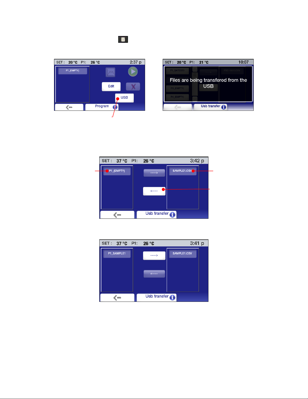
Uploading a Saved Event — Press to access the Main menu and then touch the Program icon. The
Program sub-menu will appear:
Initiates upload
Select a location for the program you wish to upload and touch the USB icon. A message will briefly
appear indicating that the file is being transferred from the USB followed by the file transfer screen.
Select the destination for the upload, select the program you wish to upload, and then touch the left arrow
icon.
Selects program for upload Selects upload destination
Uploads file
Once the file transfer is complete, the program name will appear on the program list.
110-515 PSC/EN
46
Page 48

Scheduling an Event
Manual Start
Press
to access the Main menu and then touch the Program icon. The Program sub-menu will
appear:
Starts event
Previews selected event
Select the Event and touch the Start icon to begin running immediately.
IMPORTANT: If the actual bath temperature is above or below the initial Step Start temperature,
cooling (if the circulator is refrigerated) or heating will be applied to bring the bath to the Step Start
temperature. Once that temperature has been achieved, the Event will begin running.
Automatic Start
This function allows you to schedule an event to begin running automatically at a predetermined time and
date. The Circulator must be Off (in Standby); it will turn On automatically and begin running the event at
the scheduled time.
To schedule such an event, press
to access the Main menu and then touch the Time icon. The Time
sub-menu will appear:
Schedules a
time/temperature
program to run at a
future time
Touch the Schedule icon. The scheduling screen will appear:
Selects a program
to schedule
Schedules the Start date
Schedules the Start time
Deletes scheduling
information
110-515 PSC/EN
47
Page 49

Selecting an Event — Touch the event icon.
Entering the Start Date — Touch the Date icon. A calendar screen will appear.
These are dates in
the past and cannot
be selected;
Enter the date for the year, month, and date you want the program to Start on. Touch
scheduled Start date,
to cancel.
Entering the Start Time — Touch the Time icon. A time entry screen will appear:
Selects a specific day in
the displayed month
Touch to change year, month,
or day using up and down
arrow icons
to accept the
Enter the Start time for program. Touch
to accept the scheduled Start time,
to cancel. A screen will
appear showing the date and time at which the program is scheduled to run.
Deleting a Scheduled Event
— To delete a scheduled program, select that program and then touch the
No Scheduled Program icon. Scheduling information for that event will be cleared.
Scheduled Event Reminder – When a program has been scheduled to run at a future date and time, the
Program/Event icon on the Status Bar illuminates.
Scheduled event reminder
110-515 PSC/EN
48
Page 50

When power is turned Off, a reminder appears on the Standby screen.
IMPORTANT: If the actual bath temperature is above or below the initial Step Start temperature,
cooling (if the circulator is refrigerated) or heating will be applied to bring the bath to the Step Start
temperature. Once that temperature has been achieved, the Event will begin running.
Running an Event
P1, P2 (if connected) and
set point temperatures
Add P2, set point, and
high/low alarm level
information to graph.
Event information
Event step graph
Touch graph to change time
scale (4 minutes to 10 days)
Pauses event
The Event Run screen includes the following:
Temperature Information — (P1) the actual bath temperature, (P2) fluid temperature as measured
by the remote temperature sensor if connected and active, and (Set) the set point for the current
temperature step.
Event Name — The name of the event that is running.
Event Information — The priority selected for the event (time or temperature), current and total
number of loops, the current and total number of steps in the loop, the final soak temperature.
Temperature Graph — Actual (P1) bath temperature is always displayed. Touching the colored
icons adds the following information to the graph: P2 temperature (blue); set point (green); high and
low alarm levels (red).
NOTE: When Alarm level information is displayed, the temperature scale on the graph expands
to accommodate those temperature extremes and may cause set point and other temperature
information to be displayed less clearly.
Stops event
Time Scale — The time scale covered by the graph may be changed by simply touching an area
within the graph. Temperature data can be displayed for periods ranging from the most recent 4
minutes to 10 days.
To temporarily stop an event, touch the Pause icon; the bath temperature will hold at the current
temperature until restarted. Press the Start icon to resume. To permanently stop an event, press the Stop
icon.
110-515 PSC/EN
49
Page 51
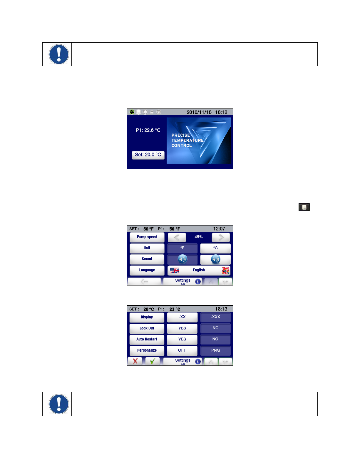
NOTE: A “paused” event can be restarted from the point it was paused (the Pause icon changes to a
Start icon). A “stopped” event cannot be restarted.
Creating and Installing a Personalized Home Screen
The Performance Digital Controller features a special home page that you can easily personalize with a
special message, favorite photo, or other image. Following is an example of a personalized home screen:
Creating the Image — The personalized home screen requires a 291 x 211 pixel Portable Network
Graphic (PNG) file. The file should be saved to a flash drive and named: PSC.png (be sure to use all
uppercase letters for PSC).
Installing the Image — Place the flash drive containing the PSC.png file in the USB A port. Press
access the Main menu and then touch the Settings icon. The Settings sub-menu will appear:
Touch to advance to page 2 of the Settings sub-menu.
Touch the PNG icon to turn personalization ON and the touch
image will now be displayed on the personalized home screen.
.The Main Menu screen will appear. Your
to
NOTE: Wait at least 30 seconds after turning personalization on before removing the flash drive from
the USB port.
110-515 PSC/EN
50
Page 52

Circulator Monitoring and Control Using an Internet Browser
NOTE: The Performance Digital Controller’s Ethernet capabilities may be used with any of the following
web browsers: Internet Explorer 9.0 or later, Firefox, Chrome, Safari, or Opera.
NOTE: A user-set password is required if you want to control (change set point, etc.) your Circulator
using an internet browser. A password is not required if all you want to do is view operation. See TCP
Control Configuration in this section for information on password setup.
The Performance Digital Controller may be connected directly to a laptop or desktop computer via its
Ethernet connection or indirectly via your facility’s wired or wireless network. Either type of connection
enables you to control and/or monitor the operation of your circulating bath in real time using an Internet
browser by entering its IP address. See Ethernet Configuration in the Technical Information section for
information on IP address and TCP control configuration.
To view Circulator status using an internet browser, enter its IP address in the browser address bar. A
screen will appear with the following information and interactive fields:
Set point
temperature
temperature reading
temperature reading
(password required)
P1 internal
P2 external
Login for TCP
control
Serial command entry
Double-click to access
command list
Temperature trend
graph
Scales from 4
minutes to 10 days
Setting / value field
Read commands: shows current setting or value
Set commands: enter desired setting or value
110-515 PSC/EN
51
Page 53

Calibration
CAUTION: The maximum calibration offset for any given temperature point is ±2.0°C. When
calibrating at 2 or more temperature points, there must be at least a 50°C span between the lowest
calibration temperature and the highest calibration temperature. Calibrations are always performed in
degrees C.
The Performance Digital Temperature Controller features 10-point calibration capability for both the
internal and optional external temperature probes. To access the Calibration function, touch the Service
icon on the Main Menu and then advance to page 2 of the Service sub-menu.
Selects
Calibration
Touch the Calibration key. The following screen will appear:
Selects temperature probe to
P1 = Internal;P2 = External
Number of calibration points:
Begins calibration
procedure for selected
temperature probe
calibrate
1 to 10
Displays current calibration
settings for selected
temperature probe
Select the temperature probe to calibrate, enter the number of calibration points (1 to 10), and then touch
the Calibrate key. A password entry screen will appear:
Enters Calibration
password:
1234
Accepts password
entered
Enter the Calibration password (1234) and touch OK. The following screen will appear:
110-515 PSC/EN
52
Page 54

Temperature probe being
calibrated
P1 = Internal; P2 = External
Calibration value
(this should match the
reading on the
calibrated reference
thermometer)
Actual temperature
sensor reading
Current calibration point
and total number of
calibration points
Increase/decrease
calibration value
Touch to make set point
adjustments directly from
this screen
Advances to next calibration
point
Proceed as follows:
1. Place the calibrated reference thermometer in the bath at the location to be calibrated.
2. Enter the set point temperature for the calibration point and allow the bath to stabilize at that
temperature.
3. Enter the reading from the calibrated reference thermometer. An offset up to ±2.0°C is allowed.
4. Press the > key. The calibration screen for the next calibration point will appear.
5. Proceed as outlined in steps 2 through 4 above until all calibration points have been entered. Be sure
to allow the bath to stabilize at the new set point temperature before entering the calibration value for
each point.
6. Once all the calibration points have been entered, touch the > key. The following screen will appear:
Actual temperature
sensor readings
Calibrated readings
Accepts calibrated
values
110-515 PSC/EN
53
Page 55

Restoring All Factory Default Values
CAUTION: All time/temperature programs, calibrations, and other user-set values are erased when
Factory default values are restored. Be sure to save any programs you wish to keep to a flash drive
and record any settings that you have changed.
Touch the Control icon on the Main Menu and then advance to page 2 of the Control sub-menu:
Touch the Reset Memory and Reboot key. A password entry screen will appear:
Enters Restore
Defaults password
1234
Restores Factory
default values
Accepts password
entered
Enter the Restore Defaults password (1234) and touch OK. The Temperature Controller will power down
and then reboot in Standby.
System Restoration
CAUTION: All firmware updates made will be lost when a system restoration is performed. All
operational settings will also be returned to the original factory defaults. Be sure to save any programs
you wish to keep to a flash drive and record any settings that you have changed.
Should you need to restore the Performance Digital Controller to its original factory configuration
(firmware as well as all default operational settings), you may do so using its built-in system restoration
utility. System restoration is performed as follows:
1. Turn power to the Controller OFF by pressing the Power Key on the front of the Controller.
2. Place the Power Switch/Circuit Breaker on the rear of the unit in the OFF position.
3. Return the Power Switch/Circuit Breaker to the ON position while pressing and holding the Home
Key. Continue holding the Home Key until the touch screen calibration screen appears.
4. Follow the calibration instructions on the screen. Once you complete the touch screen calibration
procedure, the hour glass image will briefly reappear and followed by the Standby screen.
5. Press the Power Key to return to normal operation.
110-515 PSC/EN
54
Page 56

Changing Your Circulator’s Viewing Angle
Your Circulator is equipped with Swivel 180™, an innovative feature which permits viewing of the
temperature display from anywhere over a 180° arc.
NOTE: There are positive stops at 45° intervals; however, the viewing angle may be set anywhere
within a 180° arc.
To change the viewing angle, slide the release latch to the right and rotate the Temperature Controller to
the desired angle. The latch release will automatically return to the locked position at every 45° positive
stop.
Swivel 180™ Latch Release
Inert Gas Purge
A 0.125 in. / 3 mm port on the rear of the Temperature Controller is provided to allow you to blanket the
surface of the liquid in the bath reservoir with nitrogen or another inert gas to help prevent condensation
and dilution of the bath fluid.
Tap Water Cooling
Tap water cooling allows for more rapid bath cool down from high temperatures and/or more precise
operation at temperatures near ambient.
Heat only Circulating Baths feature an integrated cooling coil as standard equipment. The tap water
connections are made on the rear of the unit. Two 0.25 inch / 64 mm female NPT fittings are provided for
these connections.
Polycarbonate Viscosity Baths feature a cooling coil with two 0.375 inch / 9.5 mm OD straight barb
fittings at which the fluid inlet and outlet connections can be made. Either connection may serve as the
fluid inlet or outlet. Be sure to secure the tubing with the appropriate size hose clamps.
An optional cooling coil is available for use on stainless steel and polycarbonate Open Bath systems. This
cooling coil has two 0.375 inch / 9.5 mm OD straight barb fittings at which the fluid inlet and outlet
connections can be made. Either connection may serve as the fluid inlet or outlet. Be sure to secure the
tubing with the appropriate size hose clamps.
WARNING: The fluid outlet must be connected and flow to a suitable drain or vessel located at a
level below that of the inlet.
110-515 PSC/EN
55
Page 57

Reservoir Cover Storage
Refrigerating/Heating and Heat Only Circulating Baths feature the LidDock® system to eliminate mess
when adding fluid or samples to the reservoir. Specially positioned notches in the inner lip of the top deck
allow you to stand the reservoir cover up upright over the bath opening, allowing condensate to flow back
into the bath.
Lid Positioning
Notch
Lid Positioning
Notch
110-515 PSC/EN
56
Page 58

Routine Maintenance & Troubleshooting
WARNING: Always turn your Circulator OFF and disconnect it from the electrical power outlet before
performing any maintenance or service.
WARNING: To avoid the potential for burns, allow the Circulator to cool completely before cleaning
or performing any maintenance.
WARNING: Always drain all fluid from the reservoir before moving or lifting your Circulator. Be sure
to follow your organization’s procedures and practices regarding the safe lifting and relocation of
heavy objects.
Service Sub-Menu
This sub-menu contains important information regarding the operation of your Circulator, such as the
number of days the unit and key systems have been in service as well as the number of days until air
filter and fluid maintenance is required.
Press
to access the Main menu. Touch the Service icon to access the Service sub-menu.
Page 1 Page 2
Air Filter Service Interval — This allows you to view the number of days remaining until air filter cleaning
is required and set a service interval for this maintenance (10 to 180 days). This function is active only on
Refrigerating/Heating Circulators.
Touch the + and – icons to increase and decrease the service interval; Reset returns the time remaining
to 180 days.
Fluid Service Interval — This allows you to view the number of days remaining until bath fluid
replacement is required and set a service interval for this maintenance (10 to 180 days).
Touch the + and – icons to increase and decrease the service interval; Reset returns the time remaining
to 180 days.
Clear Pump Operation — This allows you to view the length of time the pump has been operating.
Touch Clear Pump operation to reset it to 0.
Clear Cooling Operation — This allows you to view the length of time the cooling system has been
operating. Touch Clear Cooling operation to reset it to 0.
Calibration — This is allows you to calibrate the Temperature Controller. See the Calibration section of
this manual for more information.
Installation Operation — The length of time the Circulator has been operating.
110-515 PSC/EN
57
Page 59

Display Module Firmware — The version of the currently installed display module firmware.
Power Module Firmware — The version of the currently installed power module firmware.
Cooling Module Firmware — The version of the currently installed cooling module firmware.
Diagnostic Data Logging
This feature enables you to log key operational information that can be used by a service technician to
evaluate performance and diagnose problems. Logged data represents the Circulator’s performance at a
moment in time. The name of the file created is: TFTINFO.xml.
Data may be logged to a flash drive inserted in the USB A port.
1. Place a flash drive in the temperature controller’s USB A port.
2. Go to the second page of the Control sub-menu and select “Send Internal Data USB/WEB”.
Touch to log diagnostic data
3. Remove the flash drive from the USB A port.
Maintaining Clear Bath Water
Optimum temperature and moisture conditions for algae growth exist when using water as a bath fluid. To
prevent algae contamination and minimize the frequency of draining the reservoir, an algaecide such as
polyclean Bath Algaecide (004-300040) should be used.
WARNING: Do not use chlorine bleach.
110-515 PSC/EN
58
Page 60

Draining the Bath Reservoir
WARNING: Always drain all fluid from the reservoir before moving or lifting your Circulator. Be sure
to follow your organization’s procedures and practices regarding the safe lifting and relocation of
heavy objects.
WARNING: Bath fluids should be stored and disposed of according to applicable laws and
regulations.
Refrigerated / Heating and Heat only Circulating Baths
Refrigerated / Heating and Heat only Circulating Baths are equipped with a drain valve and port located
either beneath the front access panel or on the right hand side of the unit.
To drain fluid from the bath, attach a short length of suitable 11.5 mm ID / 0.45 inch ID tubing to the drain
port and secure it using a hose clamp with a minimum ID of 18 mm / 0.7 inch. Open the drain valve using
a flat blade screwdriver. When closing the valve, do not over tighten.
WARNING: Be sure to close the drain valve before refilling the bath reservoir. Do not over tighten.
Drain Valve Drain Port
110-515 PSC/EN
59
Page 61

Checking the Over-Temperature / Low Liquid Level Safety Systems
Your Circulator incorporates over-temperature and low liquid level protection according to IEC 61010-2-
010. For optimum safety, these systems should be checked at least every six months for proper
operation. These checks must be performed with the unit running.
Over-Temperature Protection
1. Press
to access the Main menu.
2. Touch the Safety icon to access the Safety sub-menu.
Safety Set
Temperature
3. Using a small, Philips head screwdriver, rotate the Safety
Set Thermostat on the rear of the Temperature Controller
until the unit shuts down. The Safety Set temperature at this
point should be the same as the actual bath temperature.
4. Return the Safety Set temperature to the desired overtemperature value.
Safety Set
Thermostat
5. Press the
Low Liquid-Level Protection
1. Set the temperature set point to ambient and allow the Circulator to stabilize at that temperature.
2. Increase the temperature set point to about 5°C above ambient and slowly drain fluid from the bath.
3. Continue draining fluid until the unit shuts down. The fluid level at this point should be approximately
3.0 inch / 7.6 cm below the underside of the Circulator’s top deck.
4. Replace the bath fluid and return to normal operation.
110-515 PSC/EN
key to return to the Main Operational Display.
60
Page 62

Cleaning Your Circulator
WARNING: It is the user’s responsibility to properly decontaminate the unit in the event hazardous
materials are spilled on exterior or interior surfaces. Consult the manufacturer if there is any doubt
regarding the compatibility of decontamination or cleaning agents.
Temperature Controller
Turn the Temperature Controller OFF by pressing and unplug power cord from the electrical outlet.
Wipe the housing with a clean cloth dampened with a mild detergent and water or mild all-purpose
cleaner.
CAUTION: Do not spray cleaning liquids directly onto the Temperature Controller or allow them to
enter the Controller’s vents. Do not use abrasives as these could scratch the housing or the digital
display.
Bath Reservoir
Bath Reservoir and Wetted Components — A concentrated bath cleaner (polyclean Bath Cleaner, part
number 004-300050) is available to remove mineral deposits from the stainless steel reservoir and the
Temperature Controller’s wetted parts. The cleaner should be added to the bath reservoir at the
prescribed dosage and circulated at 60°C / 140°F until the scale is removed.
CAUTION: Do not use steel wool to clean your Circulator’s bath reservoir.
External Surfaces — Only mild detergents and water or an approved cleaner should be used on the top
deck and other external surfaces of your Circulator. Do not allow cleaning liquids or sprays to enter the
vents on the rear of the Temperature Controller.
Pump Impeller
In the unlikely event that debris becomes lodged in the pump impeller, a soft brush can be used to
remove any lodged particles. If necessary, soak in a solution of distilled water and polyclean Bath Cleaner
to soften before brushing.
CAUTION: Do not use hard utensils or abrasive pads to remove trapped debris.
Condenser, Air Vents, and Reusable Filter
(Refrigerating / Heating Circulators only)
To keep the refrigeration system operating at optimum cooling
capacity, the condenser, removable air filter, and all air vents (front,
side, back) should be kept free of dust and dirt. Be sure to check them
on a regular basis and clean as required.
Reusable
Filter
The reusable filter is easily accessed from the front of the unit by
simply removing the access panel. Use a mild detergent and water
solution to wash off any accumulated dust and dirt. Rinse and dry
thoroughly before reinstalling.
110-515 PSC/EN
61
Page 63

Temperature Controller Removal and Re-Installation
Removal
The Temperature Controller on your Circulating Bath is designed to be easily removed from the top deck
without the use of special tools. It is removed as follows:
1. Place the tip of a small flat blade screwdriver under the retaining ring locking tab and pry up
gently.
Locking tab
2. Rotate the Temperature Controller clockwise until it stops (about 0.75 inch / 1.9 cm).
3. Lift the Controller straight up and out of the opening of the Circulator’s top deck.
110-515 PSC/EN
62
Page 64

Re-Installation
The top deck of your Circulator incorporates four pins to facilitate positioning of the Temperature
Controller when it is being reinstalled. These pins correspond to keyhole slots on the interior of the
Circulator’s retaining ring.
1. With the retaining ring locking tab oriented above one of the indents on the top deck, slowly lower
the Temperature Controller into the top deck opening until it is resting on top of the positioning
pins.
Keyhole Slot (cutaway)
Locking Tab
Positioning Pins
(4 total)
Indent
2. Gently rotate the Temperature Controller until it drops down on the positioning pins.
3. Rotate the Temperature Controller counterclockwise until the Locking Tab engages the indent on
the top deck.
110-515 PSC/EN
63
Page 65

Calibrating the Touch Screen
The Performance Digital Controller has a built-in feature that allows you to calibrate the touch screen so
that it responds more accurately to your touch. This calibration is performed as follows:
1. Turn power to the Controller OFF by pressing the Power Key on the front of the Controller.
2. Place the Power Switch/Circuit Breaker on the rear of the unit in the OFF position.
3. Return the Power Switch/Circuit Breaker to the ON position. An hour glass image will appear on
the display.
4. When the hour glass image fades away, press and hold the Home Key until the calibration screen
appears.
5. Follow the calibration instructions on the screen. Once you complete the touch screen calibration
procedure, the hour glass image will briefly reappear and followed by the Standby screen.
6. Press the Power Key to return to normal operation.
Display Module Firmware Updates
CAUTION: The current version of firmware as well as all time/temperature programs, calibrations,
and other user-set values are erased when new Display Module Firmware is installed. Be sure to
save any programs you wish to keep to a flash drive and record any settings that you have changed.
The Performance Digital Controller provides you with the ability to update its firmware should the need
arise. A firmware update is performed as follows:
1. Load the updated firmware (the file name will be: *.CMD where * = version number) in the root
directory of a flash drive. The flash drive should not contain any other versions of the firmware.
2. Turn power to the Controller OFF by pressing the Power Key on the front of the Controller.
3. Place the Power Switch/Circuit Breaker on the rear of the unit in the OFF position.
4. Insert the flash drive in the USB A port on the back of the Controller.
5. Press and hold the SET key while placing the Power Switch/Circuit Breaker to the ON position.
An hour glass image will appear on the display.
6. Continue holding the SET key until the display changes from black to white. Release the SET key
when the message “Checking Image…This process takes several minutes, please wait” appears.
7. When “Standby” appears on the display, place the Power Switch/Circuit Breaker in the OFF
position.
8. Return the Power Switch/Circuit Breaker to the ON position.
9. When “Standby” appears on the display, turn the Controller ON by pressing the Power Key on the
front panel.
10. Press the Menu Key to access the Main Menu, select Service, and then verify that the Display
Module Firmware version displayed on page 2 of the Service sub-menu matches the one you just
loaded.
11. Return to the Main Menu, select Control, and then select Reset Memory and Reboot on page 2 of
the Control sub-menu.
12. Enter the Restore Defaults password (1234) and touch OK. The Temperature Controller will
power down and then reboot in standby.
NOTE: See System Restoration for information on restoring the Temperature Controller’s original
version of firmware.
110-515 PSC/EN
64
Page 66

Warning and Fault Messages
Warnings
Warnings alert you to conditions such as the disconnection of the external temperature sensor or that the
desired set point is above or below the user-set limits. The warning message appears briefly on the status
bar when the condition is detected. It also appears when power is turned Off and then back On.
Warning message
Warning Message Cause Corrective Action
The set point is above the high limit Desired set point temperature is
above High Limit setting
The set point is below the low limit Desired set point temperature is
below Low Limit setting
Probe 2 has been disconnected External temperature probe
disconnected
The set point is above the safety set
point
Service air filter and reset Air filter cleaning maintenance
The fluid should be replaced Bath fluid replacement
The fluid is above the high alarm Bath fluid temperature above High
The fluid is below the low alarm Bath fluid temperature is below
Desired set point temperature is
above the safety set temperature
reminder
maintenance reminder
Alarm setting
Low Alarm setting
Lower set point temperature or
increase High Limit setting
Raise set point temperature or
decrease Low Limit setting
Reconnect external temperature
probe or select internal (P1) control.
Lower set point or increase safety
set temperature
Clean air filter and reset service
reminder
Replace bath fluid and reset service
reminder
Allow bath fluid to cool or increase
High Alarm setting
Allow bath fluid to warm or
decrease Low High Alarm setting
110-515 PSC/EN
65
Page 67

Faults
Faults alert you to conditions which may compromise safety or component failures which affect
performance. When a fault condition is detected, power to the heater, condenser, and pump are
disconnected and a fault message appears continuously on the display. The fault message includes the
type of fault, cause, and corrective action.
Corrective action
Fault condition
Fault Messages Cause Corrective Action
COOLING MODULE
DISCONNECTED
EXTERNAL PROBE FAILURE
Note: This fault will only appear if
External (P2) Control is active.
HIGH ALARM
HIGH SAFETY ALARM
INTERNAL FAILURE An internal failure may have
INTERNAL PROBE FAILURE The internal temperature probe
LOW ALARM The fluid temperature is lower than
LOW LIQUID LEVEL.
LOW LIQUID LEVEL DETECTED Low liquid level has been detected
The refrigeration control module,
detected when the unit was last
powered, is no longer present.
The external temperature probe
may have failed.
The fluid temperature exceeds the
High Alarm setting. Fluid is too
warm.
The fluid temperature exceeds the
Safety Set.
occurred.
may have failed.
the Low Alarm. Fluid is too cold.
The float switch has activated.
through either activation of the float
switch or the detection of an overtemperature condition.
Reconnect the refrigeration control
cable and re-power unit.
Check that the external
temperature probe is plugged in
correctly. Inspect probe for damage
such as frayed or exposed wires. If
problem persists, please contact
your supplier.
Decrease fluid temperature or
increase High Alarm setting. If
problem persists, please contact
your supplier.
Check fluid level. Check fluid
temperature and set point. Ensure
that Safety Set is higher than the
fluid set point. If problem persists,
please contact your supplier.
Check your set up. If problem
persists, please contact your
supplier.
If problem persists, please contact
your supplier.
Increase temperature set point or
decrease Low Alarm setting. If
problem persists, please contact
your supplier.
Check the fluid level in the bath,
and add more fluid if required.
Recheck your fluid level, and
recheck your alarm settings.
110-515 PSC/EN
66
Page 68

Troubleshooting Chart
Problem Possible Causes Corrective Action
Unit does not run
No power to unit Check that the electrical cord is secure and
(Digital Display is
blank)
Unit does not run
Unit in Standby mode Press Power Key on front panel.
(STANDBY appears
on Digital Display)
No fluid circulation Insufficient fluid in reservoir
Pump impeller jammed
Insufficient circulation Fluid viscosity too high
External tubing diameter
too small
Low line voltage
Unit does not heat Insufficient fluid in reservoir
Temperature set point too
low
Safety Set Temperature too
low
Insufficient heating Insufficient circulation
Low line voltage
Ambient temperature too
cool
Excessive heat loss
connected to an operating electrical outlet.
Add fluid to reservoir.
Inspect pump and remove debris as required.
Replace with lower viscosity bath fluid.
Replace with larger diameter tubing.
Check and correct as required.
Add fluid to reservoir.
Increase temperature set point.
Increase Safety Set temperature.
See Insufficient Circulation, above.
Check and correct as required.
Increase ambient temperature or relocate unit.
Check for heat loss from external tanks and
hoses;
Check for vapor/heat loss from internal
reservoir.
Temperature
unstable
Insufficient circulation
Debris or mineral build-up
Check pump flow and operation.
Clean as required.
on pump, heater, or
temperature sensor.
Unit does not cool Dust build up on air filter or
condenser
Blocked air ventilation
screens
Temperature set point is
too high
Excessive heat load
Ambient air temperature too
high (>35°C / 95°F)
Low or high line voltage
Clean air filter and/or condenser as required.
Remove blockages as required.
Decrease temperature set point.
Check that heat load does not exceed capacity
of bath; correct as required.
Decrease ambient air temperature.
Check and correct as required.
110-515 PSC/EN
67
Page 69

Problem Possible Causes Corrective Action
Insufficient cooling Dust build up on air filter or
condenser
Blocked air ventilation
screens
Temperature set point is
too high
Excessive heat load
Ambient air temperature too
high (>35°C / 95°F)
Low or high line voltage
Unable to achieve
low end extreme
temperatures
Pump speed too high
Incorrect bath fluid
Insufficient insulation on
external fluid lines
Ambient air temperature too
high (>35°C / 95°F)
Low or high line voltage
Dust build up on air filter or
condenser
Blocked air ventilation
screens
Excessive heat load
Clean air filter and/or condenser as required.
Remove blockages as required.
Decrease temperature set point.
Check that heat load does not exceed capacity
of bath; correct as required.
Decrease ambient air temperature.
Check and correct as required.
Reduce pump speed.
Check that the fluid being circulated is capable
of reaching the required temperature.
Check external fluid lines for proper insulation.
Decrease ambient air temperature as required.
Check and correct as required.
Clean air filter or condenser as required.
Remove blockages as required.
Check that heat load does not exceed capacity
of bath; correct as required.
110-515 PSC/EN
68
Page 70

Technical Information
Performance Specifications
Operating Temperature Range: Model dependent; see table below
Temperature Stability: ±0.005°C (±0.01°F)
Pump Type: Variable speed pressure/suction
60Hz models
50Hz models
Maximum Pressure: 4.3 psi (0.30 bar) 3.6 psi (0.25 bar)
Maximum Pressure Flow Rate: 5.3 gpm (20.1 lpm) 4.4 gpm (16.7 lpm)
Maximum Suction Flow Rate: 3.9 gpm (14.7 lpm) 3.2 gpm (12.2 lpm)
Heater Wattage: 1100 watts 2200 watts
Model Type
PD07R-20 Refrigerating / Heating Bath 7 liters
PD07R-40 Refrigerating / Heating Bath 7 liters
PD7LR-20 Refrigerating / Heating Bath 7 liters
PD15R-30 Refrigerating / Heating Bath 15 liters
PD15R-40 Refrigerating / Heating Bath 15 liters
PD20R-30 Refrigerating / Heating Bath 20 liters
PD28R-30 Refrigerating / Heating Bath 28 liters
PD45R-20 Refrigerating / Heating Bath 45 liters
PD07H200 Heating Only Bath 7 liters
PD15H200 Heating Only Bath 15 liters
PD20H200 Heating Only Bath 20 liters
PD28H200 Heating Only Bath 28 liters
1. Maximum operating temperature at which ±0.005°C temperature stability can be maintained; Performance Digital Controller is capable of higher
temperatures.
Environmental Conditions Indoor use only
Specifications subject to change without notice.
Reservoir
Capacity
Maximum Altitude: 2000 meter
Operating Ambient: 5° to 35°C (41° to 95°F)
Relative Humidity: 80%, non-condensing
Installation Category: II
Pollution Degree: 2
Ingress Protection: IP 31
Climate Class: SN
Software Class: B
Output Waveform: Sinusoidal
Temperature
Range
-20° to 200°C
-4° to 392°F
-40° to 200°C
-40° to 392°F
-20° to 200°C
-4° to 392°F
-30° to 200°C
-22° to 392°F
-40° to 200°C
-40° to 392°F
-30° to 200°C
-22° to 392°F
-30° to 200°C
-22° to 392°F
-25° to 135°C
-13° to 275°F
Ambient +10° to 200°C
Ambient +20° to 392°C
Ambient +10° to 200°C
Ambient +20° to 392°F
Ambient +10° to 200°C
Ambient +20° to 392°F
Ambient +10° to 200°C
Ambient +20° to 392°F
(1)
Electrical Requirements
60Hz 50Hz
120V, 60Hz,
12A
120V, 60Hz,
12A
120V, 60Hz,
12A
120V, 60Hz,
13A
120V, 60Hz,
13A
120V, 60Hz,
13A
120V, 60Hz,
13A
208-240V,
50/60Hz, 13A
120V, 60Hz,
10A
120V, 60Hz,
10A
120V, 60Hz,
10A
120V, 60Hz,
10A
240V, 50Hz,
12A
240V, 50Hz,
12A
240V, 50Hz,
12A
240V, 50Hz,
13A
240V, 50Hz,
13A
240V, 50Hz,
13A
240V, 50Hz,
13A
208-240V,
50/60Hz, 13A
240V, 50Hz,
10A
240V, 50Hz,
10A
240V, 50Hz,
10A
240V, 50Hz,
10A
110-515 PSC/EN
69
Page 71

Reservoir Fluids
Depending on your needs, a variety of fluids can be used with your Circulator. No matter what bath fluid is
selected, it must be chemically compatible with the reservoir and the materials in your Circulator. It must
also be suitable for the desired temperature range.
WARNING: When using Class III flammable fluids per DIN 12876-1, the user must attach the
following warning labels to the front of the unit so that they are well visible:
Warning Label
W09
Colors: Yellow/black
Mandatory Label
M018
Colors: Blue/white
Or
Semi S1-0701
Table A1-2 #9
Colors: Blue/white
WARNING: Always use fluids that satisfy safety, health, and equipment compatibility requirements.
Be aware of the chemical hazards that may be associated with the bath fluid used. Observe all safety
warnings for the fluids used as well as those contained in the material safety data sheet.
Danger Area.
Attention! Observe instructions
(operating manual, safety data sheet)
Carefully read the user information prior to
beginning operation.
Scope: EU
Carefully read the user information prior to
beginning operation.
Scope: NAFTA
For optimum temperature stability, the fluid’s viscosity should be 50 centistokes or less at its lowest
operating temperature. This permits good fluid circulation and minimizes heating from the pump.
For temperatures from 10°C to 90°C, distilled water is recommended. For temperatures below 10°C, a
mixture of laboratory grade ethylene glycol and water should be used. Do not use deionized water.
The following chart is intended to serve as a guide in selecting a bath fluid for your application. For
optimum temperature stability and low vaporization, be sure to stay within the fluid's normal temperature
range.
110-515 PSC/EN
70
Page 72

You are responsible for proper selection and use of the fluids. Avoid extreme range operation.
Viscosity
Fluid Description
distilled water 1 50°C 1.00 4.18 10° to 90°C 2° to 100°C
polyclear MIX 30 1 50°C 1.00 4.18 15° to 90°C 2° to 100°C
polytherm S150 50 100°C 0.41 1.71 50° to 150°C 5° to 270°C*
polytherm S200 125 150°C 0.40 1.67 100° to 200°C 80° to 232°C*
polytherm S250 500 200°C 0.39 1.63 150° to 250°C 125° to 260°C*
polytherm M170 40 85°C 0.40 1.67 50° to 170°C 25° to 190°C
polycool HC -50 3 -30°C 0.62 2.59 -50° to 100°C -62° to 118°C
polycool EG -25
(50/50 mix with distilled H
polycool EG -25
(30/70 mix with distilled H
polycool PG -20
(50/50 mix with distilled H
polycool PG -20
(30/70 mix with distilled H
polycool MIX -25
(50/50 mix with distilled H
polycool MIX -25
(30/70 mix with distilled H
O)
2
O)
2
O)
2
O)
2
O)
2
O)
2
(cSt)
@ 25°C
20 -20°C 0.78 3.26 -25° to 100°C -30° to 115°C
12 0°C 0.89 3.72 0° to 95°C -15° to 107°C
20 -10°C 0.83 3.47 -20° to 100°C -30° to 115°C
12 5°C 0.92 3.85 5° to 90°C -10° to 107°C
20 -20°C 0.78 3.26 -25° to 100°C -30° to 115°C
12 0°C 0.89 3.72 0° to 95°C -15° to 107°C
@ Fluid
Temperature
Specific Heat
BTU/lb°F KJ/Kg°C
Normal
Temperature
Range
Extreme
Temperature
Range
*WARNING: This is the fluid’s flash point temperature.
WARNING: DO NOT USE THE FOLLOWING LIQUIDS
• Automotive antifreeze with additives**
• Hard tap water**
• Deionized water with a specific resistance > 1 meg ohm
• Concentrations of acids or bases
• Solutions with halides: chlorides, fluorides, bromides, iodides or sulfur
• Bleach (Sodium Hypochlorite)
• Solutions with chromates or chromium salts
• Glycerine
• Syltherm fluids
** At temperatures above 40°C, additives or mineral deposits can adhere to the heater. If deposits
are allowed to build up, the heater may overheat and fail. Higher temperatures and higher
concentrations of additives will hasten deposit build up.
110-515 PSC/EN
71
Page 73

Application Notes
At a fluid's low temperature extreme:
• The presence of ice or slush adversely affects temperature stability.
• A viscosity above 10 centistokes adversely affects temperature uniformity.
• A high fluid viscosity and high pump speed adds heat to the fluid being pumped.
At a fluid's temperature above ambient without refrigeration:
• If your set point temperature is less than 15°C above the ambient temperature, the viscosity of the
fluid should be 10 centistokes or less to minimize friction heating of the fluid.
• Heat loss should be encouraged by uncovering the fluid and lowering the pump speed.
At fluid's high temperature extreme:
• Heat loss from vapor adversely affects temperature stability.
• To prevent the accumulation of vapors inside the room, the reservoir may need to be placed in a
fume hood.
• Use a cover and/or floating hollow balls to help prevent heat and vapor loss.
• Replenish fluid lost from vapor frequently.
Tubing and Fitting Temperature Ranges
Material Temperature Range
Buna N tubing -40° to 120°C
Viton® tubing -32° to 200°C
Braided Teflon® lined tubing -50° to 225°C
Stainless steel fittings -45° to 225°C
Nylon fittings -40° to 90°C
Brass fittings -40° to 80°C
Fluid Compatibility
polycool EG -25 A A A B A B
polycool PG -20 A A A B B
polycool HC -50 B B A B B B
polytherm S150 B B A B B
polytherm S200 B B A B B
polytherm S250 B B A B B
polytherm M170) A A A A B
polycool MIX -25 A A A B A B
polyclear MIX 30 A A A A A A
Buna N
Tubing
Viton
Tubing
Braided
Teflon
Tubing
Stainless
Steel Fittings
Nylon
Fittings
Brass
Fittings
A = Excellent B = Good
110-515 PSC/EN
72
Page 74

RS232/RS485 Communications
CAUTION: Always turn electrical power to the Circulator OFF before making a connection to the
serial (DB9) port.
Serial Connector — A DB9 connector is provided on the back panel of the Controller for RS232/RS485
data communication.
Pin RS232 RS485
1
2 TX A
3 RX
4 DTR
5 GND GND
6 DSR
7 RTS
8 CTS B
9
Serial Communications Protocol — The Controller uses the following serial communications settings:
Data bits — 8
Parity — None
Stop bits — 1
Flow control — None
Baud rate — Selectable (Controller/PC baud rates must match). 57600 is recommended.
Communications Commands
— RS232 commands must be entered using the command only; RS485
commands must be entered using @ and the RS485 address (E.g., @001) followed by the actual
command. All commands must be entered in the exact format shown. Do not send a [LF] (line feed) after
the [CR] (carriage return). Be sure to follow character case exactly.
A response followed by an exclamation point (!) indicates that a command was executed correctly. A
question mark (?) indicates that the Controller could not execute the command (either because it was in
an improper format or the values were outside the allowable range). A response must be received from
the Controller before another command can be sent. All responses are terminated with a single [CR].
110-515 PSC/EN
73
Page 75

Command Format Values
Set Command Echo SEi[CR]
Echo: i = 1
No Echo: i = 0
Return
Message
![CR]
Set Set Point SSiii.ii[CR] i = any integer from 0-9 ![CR]
Set On Off SOi[CR]
On: i = 1
Off: i = 0
![CR]
Set High Alarm SHiii[CR] i = any integer from 0-9 ![CR]
Set Low Alarm SLiii[CR] i = any integer from 0-9 ![CR]
Set Pump Speed SMi[CR]
Set Restart Power Status SWi[CR]
Set Internal / External Control SJi[CR]
i = any integer from 5-100 in
increments of 5
Restart: i = 1
Standby: i = 0
External: i = 1
Internal: i = 0
![CR]
![CR]
![CR]
Read Set Point Temperature RS[CR] iii.ii[CR]
Read Temperature Unit RU[CR] C[CR] or F[CR]
Read Internal Temperature RT[CR] iii.ii[CR]
Read External Temperature RR[CR] iii.ii[CR]
Read Operating Status RO[CR]
Running: i = 1
Standby: i = 0
i[CR]
Read High Alarm Setting RH[CR] iii[CR]
Read Low Alarm Setting RL[CR] iii[CR]
Read Pump Speed RM[CR]
Read Alarm Status RF[CR]
Low: i = 1
High: i = 2
No Faults: i = 0
Fault: i = 1
i[CR]
i[CR]
Read the Auto-Cool Set Point RA[CR] ii[CR]
Read Number of Program
Running
Read Number of Steps in
Program Running
Read Number of Loops in
Program Running
RV[CR] ii[CR]
Rs[CR] ii[CR]
RK[CR] ii[CR]
Read Current Program Step RC[CR] ii[CR]
Running: i = 1
Read Program Status RG[CR]
Stopped: i = 0
i[CR]
Paused: i = 2
Read Current Program Loop RI[CR] ii[CR]
Read Elapsed Time from
Program Start
RE[CR] Format: h:mm:ss ii[CR]
Read the Firmware Version RB[CR] i-ii-iii[CR]
110-515 PSC/EN
74
Page 76

Remote ON / OFF
WARNING: Always turn electrical power to the Circulator OFF before making a connection to the
serial (DB9) port.
The DB9 connector on the rear of the Temperature Controller can also be used to turn the Circulator ON
or OFF via a contact closure or VDC control room signal.
Contact Closure — To use a contact closure to turn the Circulator ON and OFF, connect pin 1 to 5. The
Circulator will be ON when the switch is closed and OFF when the switch is open.
VDC Signal — To use a VDC signal to turn the Circulator ON and OFF, connect to pins 9 (Positive) and 5
(Ground). The Circulator will be ON when a +9 to +24 VDC signal is applied; it will be OFF when the
signal is removed.
USB Data Logging
Data is stored in a CSV file that can be read in spreadsheet programs such as Microsoft Excel®. The data
is output in the following format:
MIN.SEC [V] UNIT SET P1 P2
4 [v0013] C 10 15.19 14.89
4 [v0013] C 10 15.18 14.88
4.22 [v0013] C 10 15.03 14.71
4.23 [v0013] C 10 15.02 14.7
4.24 [v0013] C 10 15 14.69
4.25 [v0013] C 10 15 14.69
4.26 [v0013] C 10 14.99 14.68
4.27 [v0013] C 10 14.98 14.67
MIN.SEC = Minutes and seconds.
V = Firmware version.
UNIT = Selected temperature unit.
SET = Temperature set point
P1 = Fluid temperature as measured by the Internal probe
P2 = Fluid temperature as measured by the External probe (if connected)
NOTE: The time stamp on the first line of data represents the time when data began being logged. The
time stamp will indicate 0.01 if data logging was enabled after a flash drive or computer was connected
to the USB port. It will show a later time if data logging was enabled before the storage device was
connected. In the example shown above, the flash drive was connected to the USB port 4 minutes after
data logging was enabled.
110-515 PSC/EN
75
Page 77

USB B Setup, Monitoring, and Control
The Performance Digital Temperature Controller can be monitored and controlled using a personal
computer connected to its USB B port.
Initial Setup
1. Plug the USB A connector of a USB A to USB B cable into an open USB port on the personal
computer and plug the USB B connector into the corresponding port on the Temperature
Controller.
2. The computer operating system will automatically detect a new device and ask to install the
drivers for the device. The drivers are located on the Resource Disk that came with your
Temperature Controller.
3. Place the Resource Disk in the computer’s CD drive and install the drivers.
4. Determine the identity of the communications port your computer assigned to the Temperature
Controller.
Monitoring and Control
When all connections have been made and drivers installed, you can monitor and control the
Temperature Controller using a terminal program and the active serial communications commands.
Ethernet Configuration
NOTE: The Performance Digital Controller’s Ethernet capabilities may be used with any of the following
web browsers: Internet Explorer 9.0 or later, Firefox, Chrome, Safari, or Opera.
The Performance Digital Controller may be connected directly to a laptop or desktop computer via its
Ethernet connection or indirectly via your facility’s wired or wireless network. Either type of connection
enables you to control and/or monitor the operation of your circulating bath in real time using an Internet
browser by entering its IP address. The Controller’s active serial communications commands are used to
retrieve and/or change operational information.
Direct Computer to Controller Configuration
NOTE: If your computer is already connected to a wired network, you will not be able to directly
connect it to your circulating bath’s Temperature Controller.
1. Open the utility that displays your computer’s available network connections.
2. Select an available wired connection.
3. Enter the following properties for the selected connection:
A. Internet protocol: TCP/IP
B. IP address: any three sets of identical numbers (e.g., 111.111.111) followed by a single
digit (e.g., 111.111.111.5).
C. Subnet mask: 255.255.255.0
4. Enter the IP address into your Controller as outlined in Static IP Addressing, below. Please note
that the first three series of numbers in IP address on the Controller must match those entered in
Step 3B, above. The last number does not have to match.
110-515 PSC/EN
76
Page 78

Wired or Wireless Network Configuration
The Performance Digital Controller supports both dynamic (DHCP) and static IP configuration. The
default value is Static. With either type of IP configuration, it may be necessary to work with your IT
department to ensure that both the network and your Controller are configured properly.
1. Press
2. Touch Connect to access the Connect sub-menu.
to access the Main Menu.
3. Touch Ethernet to access the IP address screen. Depending on the current configuration, one
of the following screens will appear:
Static IP address screen Dynamic IP address screen
Static IP Addressing — If your Controller will be connected directly to a computer or your network uses
static IP addressing, you must manually enter the IP address that will be used into your Controller. This is
done as follows:
1. Select Static and touch
Selects Static IP addressing
2. Select an IP address field, enter the correct IP address, and touch
Repeat for the first three
IP address fields.
110-515 PSC/EN
77
Page 79

IP address
fields
Dynamic IP Addressing — If your network uses DHCP (Dynamic Host Configuration Protocol), all you
need to do is set your Controller for DHCP. The correct address will appear automatically when you
connect the Controller to the network.
IP address
assigned
Selects
dynamic
(DHCP) IP
addressing
automatically
TCP Control Configuration
In order to make operational changes (set point, high/low limits and alarms, etc.) through an internet
browser, the TCP Control function must be ON and a password set on the Temperature Controller’s IP
settings screen. You must enter this password in the browser screen’s Login field before you are allowed
to change the Temperature Controller’s operational settings.
TCP control is turned ON and a password created as follows:
1. Select Ethernet from the Connect sub-menu. The IP settings screen will appear:
Touch to create a
password allowing control
using an internet browser
2. Select Password, create a password (8 characters maximum), and touch .
3. Turn TCP Control ON and touch
110-515 PSC/EN
78
Page 80

External Cooling Control
Touch to turn TCP Control ON
CAUTION: External Cooling Control settings are always displayed and set in °C.
NOTE: The Circulator must be equipped with the optional external cooling control valve in order to use
this function. Refer to the instructions included with the optional External Cooling Control Valve for
installation information.
External cooling control provides you with a means of quickly cooling the bath fluid after a period of
operation at an elevated temperature. When properly configured, it also prevents the bath from cooling to
a temperature below that which is intended.
General Operation
External cooling control allows you to initiate a controlled cool down of the bath fluid after operation at an
elevated temperature by automatically and incrementally closing the valve as the bath temperature
decreases.
1. When the bath temperature is above the Maximum Set value, the external cooling valve is fully
open (100%).
2. When bath temperature is between the Maximum Set and Minimum Set values, the external
cooling valve is partially open (user-adjustable from 10% to 90%).
3. When the bath temperature is below the Minimum Set value, the external cooling valve is fully
closed (0%).
Configuring External Cooling Control
1. Select External Cooling Control from the second page of the Control sub-menu. The External
Cooling Control setup screen will appear.
Touch to access External
Cooling Control setup
110-515 PSC/EN
79
Page 81

Touch to change the
corresponding value
2. Enter the desired Maximum Set, Minimum Set, and Valve % values for the external cooling valve.
Select a value to change by touching the corresponding button. Enter the desired value using the
numeric keypad that appears and then touch to accept the new value.
Maximum Set — At bath temperatures above this value, the valve will be open 100%. The
Maximum Set value can be set from 40° to 80°C.
Minimum Set — At bath temperature below this value, the valve will be fully closed. The
Minimum Set value can be set from 20° to 35°C.
Valve % — This is the valve setting when bath temperature is between the Maximum Set and
Minimum Set values. The Value % can be set from 10% to 90% open.
3. Touch to accept the new external cooling control settings.
Operating External Cooling Control
CAUTION: Be sure to deactivate external cooling control once bath temperature has cooled to the
desired temperature. Failure to do so may result in excessive energy consumption and/or make it
difficult to maintain a bath temperature that is higher than the Minimum Set value.
To initiate a cool down using external cooling control, select External Cooling Control from the second
page of the Control sub-menu, touch Start and then . The external cooling control valve will open (fully
or partially, depending on bath temperature and settings). The external cooling control valve will
automatically close once the bath temperature reaches the Minimum Set value.
Touch to initiate cool down
110-515 PSC/EN
80
Page 82

When the bath has cooled to the desired temperature, external cooling control can be deactivated by
selecting External Cooling Control from the Control sub-menu, touching Stop, and then .
Touch to stop cool down
Equipment Disposal (WEEE Directive)
or
This equipment is marked with the crossed out wheeled bin symbol to indicate it is covered by the Waste
Electrical and Electronic Equipment (WEEE) Directive and is not to be disposed of as unsorted municipal
waste. Any products marked with this symbol must be collected separately, according to the
regulatory guidelines in your area.
It is your responsibility to correctly dispose of this equipment at lifecycle-end by handing it over to an
authorized facility for separate collection and recycling. It is also your responsibility to decontaminate the
equipment in case of biological, chemical and/or radiological contamination, so as to protect the persons
involved in the disposal and recycling of the equipment from health hazards. By doing so, you will help to
conserve natural and environmental resources and you will ensure that your equipment is recycled in a
manner that protects human health.
Requirements for waste collection, reuse, recycling, and recovery programs vary by regulatory authority
at your location. Contact your local responsible body (e.g., your laboratory manager) or authorized
representative for information regarding applicable disposal regulations.
110-515 PSC/EN
81
Page 83

Replacement Parts & Accessories
Description
IEC to IEC Power Cord (Refrigerating/Heating Circulators) 120V, 60Hz 225-661
IEC to Mains Power Cord, U.S. plug type, 120V, 60Hz
(7 to 28 liter Refrigerating/Heating Circulators)
IEC to Mains Power Cord, U.S. plug type, 230V, 60Hz
(45 liter Refrigerating/Heating Circulators)
IEC to Mains Power Cord, European plug type, 240V, 50Hz
(Refrigerating/Heating Circulators)
IEC to Mains Power Cord, U.S. plug type, 120V, 60Hz (Heating Circulators) 225-227
IEC to Mains Power Cord, European plug type, 240V, 50Hz (Heating Circulators) 225-228
Refrigeration Control Cable (Refrigerating/Heating Circulators) 225-651
Reservoir Cover for 7L Refrigerating/Heating and Heat only Circulators 300-674
Reservoir Cover for 15L Refrigerating/Heating and Heat only Circulators 300-694
Reservoir Cover for 20L Refrigerating/Heating and Heat only Circulators 300-697
Reservoir Cover for 28L Refrigerating/Heating and Heat only Circulators 300-700
Reservoir Cover for 45L Refrigerating/Heating and Heat only Circulator 300-703
Bypass Tubing Kit, Buna N 510-711
Part
Number
225-473
225-230
225-346
Bypass Tubing Kit, Viton 510-495
Teflon-lined Tubing, stainless steel overbraid 060310
RS232 Cable, 9.8-ft (3 m) 225-173
USB A to USB B Cable, 6-ft (1.8 m) 225-669
Ethernet cable, 7-ft (2.1 m) 225-670
Flash Drive, 1 GB 250-096
Pt100 External Temperature Probe, 2-ft (0.6 m) 525-876
Pt100 External Temperature Probe, 10-ft (2 m) l 525-870
Pt100 External Temperature Probe, 25-ft (8 m) 525-871
Pt100 External Temperature Probe, 50-ft (15 m) 525-872
USB A to USB B Cable, 9-ft (3 m) 225-669
Fitting, ¼” male NPT to 1/8” (3 mm) hose barb, brass (set of 2) 060306
Fitting, ¼” male NPT to 3/16” (5 mm) hose barb, stainless steel (1 each) 776-204
Fitting, ¼” male NPT to 3/16” (5 mm) hose barb, nylon (1 each) 300-049
Fitting, ¼” male NPT to 3/16” (5 mm) hose barb, brass (1 each) 776-193
Fitting, ¼” male NPT to ¼” (6 mm) hose barb, nylon (1 each) 300-048
Fitting, ¼” male NPT to ¼” (6 mm) hose barb, brass (1 each) 776-194
Fitting, ¼” male NPT to ¼” (6 mm) hose barb, stainless steel (1 each) 776-203
110-515 PSC/EN
82
Page 84

Description
Part
Number
Fitting, ¼” male NPT to 5/16” (8 mm) hose barb, brass (set of 2) 060305-2
Fitting, ¼” male NPT to 3/8” (9.5 mm) hose barb, stainless steel (1 each) 776-202
Fitting, ¼” male NPT to 3/8” (9.5 mm) hose barb, nylon (1 each) 300-047
Fitting, ¼” male NPT to 3/8” (9.5 mm) hose barb, brass (1 each) 776-195
Fitting, ¼” male NPT to M16 x 1, stainless steel (1 each) 775-290
Fitting, M16 x 1 female to 8 mm (1/4”) hose barb, brass (1 each) 776-191
Fitting, M16 x 1 female to 12 mm (7/16”) hose barb, brass (1 each) 776-192
Fitting, ½” male NPT x ½” (13 mm) hose barb, nylon (for integrated cooling coil) 300-096
Flow Adapter, 2 ports with shutoffs. ¼” male NPT x two ¼” (6 mm) hose barbs, brass 510-666
Digital to Analog Adapter, 10 mV 215-471
Reusable Air Filter for AP7LR-20 Refrigerating/Heating Circulator 305-057
Reusable Air Filter for AP07R-20 and AP07R-40 Refrigerating/Heating Circulator 305-054
Reusable Air Filter for AP15R-30, AP15R-40, AP20R-30 and AP28R-30
Refrigerating/Heating Circulators
305-055
Reusable Air Filter for AP45R-20 Refrigerating/Heating Circulator 305-056
O-Ring, Drain Valve (for Refrigerating/Heating and Heat only Circulators) 400-843
Display Module Assembly 510-528
Bezel for Display 300-676
Circuit Breaker / Power Switch 215-330
Leveling Glide; Refrigerating/Heating and Heat only Circulators 400-814
Resource Disk (with Operator’s Manual) 110-815
110-515 PSC/EN
83
Page 85

PolyScience Circulating Bath Fluids
Circulating Bath Fluid Quantity Part Number
polyclean Algaecide 8 oz / 236 ml 004-300040
polyclean Algaecide Twelve 8 oz / 236 ml bottles 004-300041
polyclean Bath Cleaner 8 oz / 236 ml 004-300050
polyclean Bath Cleaner Twelve 8 oz / 236 ml bottles 004-300051
polycool EG -25 (ethylene glycol) 1 gal / 4.5 liter 060340
polycool PG -20 (propylene glycol) 1 gal / 4.5 liter 060320
polycool HC -50 (water-based heat transfer fluid) 1 gal / 4.5 liter 060330
polytherm S150 (silicone oil) 1 gal / 4.5 liter 060326
polytherm S200 (silicone oil) 1 gal / 4.5 liter 060327
polytherm S250 (silicone oil) 1 gal / 4.5 liter 060328
polytherm M170 (mineral oil) 1 gal / 4.5 liter 060321
polycool MIX -25 (50/50 blend polycool EG -25 /
O plus polyclean algaecide)
H
2
polyclear MIX 30 (distilled water plus polyclean
algaecide)
Five 0.5 gal / 2.27 liter 004-300060
Five 0.5 gal / 2.27 liter
004-300062
110-515 PSC/EN
84
Page 86

Service & Technical Support
If you have followed the troubleshooting steps outlined previously and your Circulator still fails to operate
properly, contact the supplier from whom the unit was purchased. Have the following information
available for the customer service person:
Model, Serial Number, and Voltage (from back panel label)
Date of purchase and purchase order number
Supplier’s order number or invoice number
A summary of the problem
Warranty
The manufacturer agrees to correct for the original user of the product, either by repair (using new or
refurbished parts), or at the manufacturer’s election, by replacement (with a new or refurbished product),
any defects in material or workmanship which develop during the warranty period. The standard warranty
is twenty-four (24) months after delivery of the product. In the event of replacement, the replacement unit
will be warranted for the remainder of the original warranty period or ninety (90) days, whichever is
longer. For purposes of this limited warranty, “refurbished” means a product or part that has been
returned to its original specifications. In the event of a defect, these are your exclusive remedies.
If the product should require service, contact the manufacturer’s/supplier’s office for instructions. When
return of the product is necessary, a return authorization number is assigned and the product should be
shipped, transportation charges pre-paid, in either its original packaging or packaging affording an equal
degree of protection to the indicated service center. To insure prompt handling, the return authorization
number must be placed on the outside of the package. A detailed explanation of the defect should be
enclosed with the item.
The warranty shall not apply if the defect or malfunction was caused by accident, neglect, unreasonable
use, improper service, acts of God, modification by any party other than PolyScience, or other causes not
arising out of defects in material or workmanship.
EXCLUSION OF IMPLIED WARRANTIES. THERE ARE NO WARRANTIES, EXPRESSED OR
IMPLIED, INCLUDING, BUT NOT LIMITED TO, THOSE OF MERCHANTABILITY OR FITNESS FOR A
PARTICULAR PURPOSE WHICH EXTEND BEYOND THE DESCRIPTION AND PERIOD AS STATED
IN THE OPERATOR’S MANUAL INCLUDED WITH EACH PRODUCT.
LIMITATION ON DAMAGES. THE MANUFACTURER’S SOLE OBLIGATION UNDER THE WARRANTY
IS LIMITED TO THE REPAIR OR REPLACEMENT OF A DEFECTIVE PRODUCT AND POLYSCIENCE
SHALL NOT, IN ANY EVENT, BE LIABLE FOR ANY INCIDENTAL OR CONSEQUENTIAL DAMAGES
OF ANY KIND RESULTING FROM USE OR POSSESSION OF THIS PRODUCT.
Some states do not allow: (A) limitations on how long an implied warranty lasts; or (B) the exclusion or
limitation of incidental or consequential damages, so the above limitations or exclusions may not apply to
you. This warranty gives you specific legal rights and you may have other rights that vary from state to
state.
Manufactured by:
PolyScience
6600 W. Touhy Avenue Niles, IL 60714 U.S.A.
1-800-229-7569 ● 1-847-647-0611
www.polyscience.com
110-515 PSC/EN
85
 Loading...