

Polymer Laboratories PL-ELS 2100, PL-ELS 2100 Ice Operator's Manual

OPERATOR’S MANUAL
FOR
PL-ELS 2100/2100
EVAPORATIVE
LIGHT SCATTERING
DETECTOR
Version 1.5
Polymer Laboratories Ltd, Essex Road, Church Stretton, Shropshire SY6 6AX, UK
Tel +44 01694 723581, Fax +44 01694 722171, Service Tel +44 01694 724333
Polymer Laboratories Varian Inc, 160 Old Farm Road, Amherst, MA 01002, USA
Tel: +1 413 253 9554, Fax +1 413 253 2476
Polymer Laboratories BV, Herclesweg 8, 4338 PL Middleburg, The Netherlands
Tel +31 118 671 500, Fax +31 118 623 193
Polymer Laboratories GmbH, PEKA Park T5 001 Otto-Hesse Straße 19 D 64293 Darmstadt,
Germany Tel +49 06151 860690, Fax +49 06151 860670
Polymer Laboratories SARL, GVIO Parc de Marseille Sud, Impasse du Paradou, Bâtiment D5, 13276
Marseille, France. Tel + 33 0491 176400, Fax + 33 0491 176401

Documentation Revision History
6/26069
Revision # Date Section
Changed
Changes Approval
Draft April 2003 All Originated
Version A
(Version 1.0)
16
th
May 2003 All Release Reviewed by
SJOD, NJW,
PEC and EM
Version B
(version 1.01)
26th August 2003 I/O Controls –remote A/Z
Control software reference
Storage/drying details QC
Specifications
SJOD
Reviewed SB
Version C
(version 1.02)
25th March 2004
19/4/04
1.2, 1.6, 2.4,
4.2
2.3
Specifications AZ input & Gas
/Gain
Gas management
Software include Gain /Smooth
Cleaning Evap tube change
from S/BY to RUN
Addition of parameter menu
info
SJOD/AW
Version D
(version 1.1)
7th May 2004 Table 2.1 &
page 17
Min gas flow 0.9SLM and S/By
flow1.2SLM
Replaced new screen pics
Version E
(version 1.1E)
3/9/04 Table 1.1
section 1.9
Contact closure pins 4 & 10
Pump stop 3 & 10
Version F (1.2) 25/07/05 French address
Version G (1.3) 31/10/05 Safety
Practices,
1.10,
Appendix 6
Cleaning & Decontamination
Procedures, N2 mandatory for
flammable solvents & pump
stop should be used
PEC
Version H (1.4) March 2006 Safety
Practices,
Health &
Safety, 1.2,
1.4 & 1.5
Digital output included.
Protective earth connection
requirement on mains supply.
Power switch & coupler
accessible at all times. IEC
60825-1 classification of LED
source.
SB/PEC
Version I
(1.5)
May 2006 All PL -ELS 2100/2100 Ice included SB
Reviewed
SJOD

i
DECLARATION OF CONFORMITY
We, Polymer Laboratories Ltd
Essex Road
Church Stretton
Shropshire SY6 6AX
U.K.
declare that the product:
______________________________________________________________________
Evaporative Light Scattering Detector
PL-ELS 2100 Part number 0860-0110/0860-0240
PL-ELS 2100 Ice Part number 0860-01110/0860-01240
______________________________________________________________________
conforms with the requirements of EC Directives 89/392, 91/368 & 89/336 by complying with the
following Harmonised European Standards:
Safety: EN61010 – 1 Class I
Installation category II
Pollution degree 2
EN61010 –2 – 010 Class 2
REINFORCED INSULATION
EMC: EN 61326:1998
Date: 17th May 2006 Dr. S.O’Donohue, Head or R&D –Instrumentation

Document # 6/26069I ii
PL-ELS 2100/2100 Ice WARRANTY
(Extract from General Conditions of Sale)
Subject as hereinafter stated, if any goods supplied are proved to the reasonable satisfaction of the Seller to be defective in material
or workmanship within a period of 12 months from the date of despatch and the Buyer notifies such defect to the Seller in writing
within fourteen days of it becoming apparent the Seller shall repair or replace at its option the goods or any part thereof free of
charge and any repaired (or replacement) goods will be guaranteed on these terms for the unexpired portion of the 12 month period
PROVIDED THAT the Seller shall be under no liability in respect of any defect that has arisen because:-
• of fair wear and tear; or
• where the goods have not been used, maintained, stored or protected in the proper manner; or
• the goods have been altered in any way whatsoever or have been subject to unauthorised repair; or
• the goods have been improperly installed or connected (unless the Seller carried out such installation and connection); or
• in the case of Instrument Consumables (lamps and wetted parts which includes the nebuliser and evaporator assemblies,)
they prove defective as aforesaid more than 30 days after delivery notwithstanding the foregoing provisions of this
condition; or
• the Buyer is in breach of any other contract made with the Seller such as the Company’s General Conditions of Sale.
SAVE AS PROVIDED ABOVE, THE SELLER WILL BE UNDER NO LIABILITY UNDER THE CONTRACT FOR ANY
PERSONAL INJURY, DEATH, LOSS OR DAMAGE OF ANY KIND WHATSOEVER WHETHER CONSEQUENTIAL OR
OTHERWISE INCLUDING BUT NOT LIMITED TO LOSS OF PROFITS AND THE SELLER HEREBY EXCLUDES ALL
CONDITIONS, WARRANTIES AND STIPULATIONS EXPRESS OR IMPLIED, STATUTORY, CUSTOMARY OR
OTHERWISE WHICH BUT FOR SUCH EXCLUSION WOULD OR MIGHT SUBSIST IN FAVOUR OF THE BUYER
EXCEPT THAT SUCH EXCLUSION WILL NOT APPLY TO ANY IMPLIED CONDITION THAT THE SELLER HAS OR
WILL HAVE THE RIGHT TO SELL THE GOODS WHEN THE PROPERTY IS TO PASS OR WHEN THE BUYER DEALS
AS A CONSUMER (AS DEFINED IN SECTION 12 OF THE UNFAIR CONTRACT TERMS ACT 1977), ANY IMPLIED
TERM RELATING TO THE CONFORMITY OF THE GOODS WITH THEIR DESCRIPTION OR SAMPLE OR AS TO
THEIR QUALITY OR FITNESS FOR A PARTICULAR PURPOSE.
IN NO CIRCUMSTANCES WILL THE SELLER OR ITS EMPLOYEES, AGENTS, OR SUB-CONTRACTORS BE LIABLE
FOR ANY LOSS OR DAMAGE OF ANY KIND WHATSOEVER WHETHER CONSEQUENTIAL OR OTHERWISE
CAUSED DIRECTLY OR INDIRECTLY BY ANY NEGLIGENCE OR OTHER TORTIOUS ACT OR BREACH OF
STATUTORY DUTY ON THE PART OF THE SELLER OR ON THE PART OF ANY OF ITS EMPLOYEES, AGENTS OR
SUB-CONTRACTORS IN CONNECTION WITH OR ARISING OUT OF THE MANUFACTURE OR SUPPLY OF THE
GOODS OR IN CONNECTION WITH ANY STATEMENT GIVEN OR MADE (OR ADVICE NOT GIVEN OR MADE) BY
OR ON BEHALF OF THE SELLER.
Any statement made about the Seller’s goods by the Seller or its servants or agents whether orally or in writing is intended for
guidance only and the Buyer should not place any reliance thereon without specific enquiry and without ensuring that any matter of
concern to him is specifically mentioned in the contract.
The Buyer is solely responsible for the suitability of the site for the installation of the goods, for obtaining all and any necessary
consents and approvals under planning and building regulations and by-laws and for the preparation of the site, the constitution of
foundations and the provision of services so that the site is suitable to receive the goods.
Unless expressly provided therein, the contract does not include the installation, erection or commissioning of any goods or
equipment or the supervision thereof. Where installation is included in the contract it is the responsibility of the Buyer to advise
the Seller of prevailing site conditions, and in particular but without prejudice to the foregoing, physical characteristics, availability
of services, normal labour working hours and any local or national labour arrangement or practices which might affect the work, and
any other relevant factors. Any additional costs caused by any interruption or delay not attributable to the Seller or to its
employees or because the Seller cannot gain access to the site shall be charged to the Buyer together with an appropriate allowance
for profit. The Buyer shall also be responsible for providing a safe and healthy working environment for the Seller’s employees and
the Seller’s subcontractors and their employees and shall bear (or reimburse the Seller against) any loss, damage or compensation
due to any person in relation to any death or personal injury or destruction or damage to property except to the extent that the
same is due to the negligence of the Seller and the Buyer shall except as aforesaid keep the Seller fully indemnified in respect
thereof.
Document # 6/26069I iii
SAFETY
Signs and Pictograms Used in this Manual
WARNING:
THE “WARNING SIGN” DENOTES A HAZARD. IT CALLS ATTENTION
TO A PROCEDURE, PRACTICE WHICH, IF NOT CORRECTLY DONE OR
ADHERED TO, COULD RESULT IN SEVERE INJURY OR DAMAGE OR
DESTRUCTION OF THE INSTRUMENT.
PLEASE DO NOT PROCEED BEYOND A WARNING SIGN UNTIL THE
INDICATED CONDITIONS ARE FULLY UNDERSTOOD AND MET.
ATTENTION:
The “ATTENTION sign” denotes relevant information.
Read this information first before proceeding, it will be helpful or
necessary to complete the task.
NOTE:
The “NOTE sign” denotes additional information.
It provides the user with advice and suggestions to facilitate the
operation of the instrument.
WARNING
!
ATTENTION
!
NOTE
!

Document # 6/26069I iv
Safety Practices
The following safety practices are intended to ensure the safe operation of the equipment.
Opening of instrument panels may expose potentially dangerous voltages. Disconnect the instrument from all power
sources before opening protective panels. Access to the interior of the instrument should be restricted to properly
trained and qualified service personnel only.
Replace defective fuses only with size and rating stipulated on the rear panel next to the fuse holder, and in the
manual.
Replace faulty or frayed power cords.
Check the actual line voltage to confirm its value, before connecting this instrument to it.
Ensure the power switch and appliance coupler at the rear of the instrument remain easily accessible at all times.
Hot surfaces may be exposed when the instrument is opened. These are indicated by a warning label. Allow these
surfaces to cool before touching them.
The individual or group responsible for the use and maintenance of this equipment must ensure that appropriate
decontamination is carried out if hazardous material is spilt on or inside the instrument.
Before using any cleaning or decontamination method except those recommended by Polymer Laboratories (see
Appendix), please check with Polymer Laboratories that the proposed method will not damage the equipment.
Perform periodic leak checks on suppl y lines.
Do not allow flammable and/or toxic solvents to accumulate.
Follow recommended procedures and protocols for evacuation and disposal of flammable and/or toxic solvents.
Never dispose of such products through municipal waste systems
The unit should not be stacked more than two high without additional means of support and suitable precautions
should be taken to prevent the units being knocked over
Eluents containing concentrations of >1% Acetic acid should be avoided
WARNING
!
ELECTRICAL HAZARDS
NOTE
!
GENERAL PRECAUTIONS
WARNING
!
CLEANING
WARNING
!
HOT SURFACE HAZARDS

Document # 6/26069I
HEALTH AND SAFETY
PL-ELS 2100/2100 Ice
WARNING: This instrument should be used only in accordance with the instructions stated within this
manual. Users should observe the following general safety precautions:
• Ensure that the instructions within this manual are understood and carried out in the operation of
the detector. All persons utilising the instrument should have adequate training in its proper setup, operation, and particularly its safety features.
• Voltages above 110V AC are present within the instrument; access covers should not be
removed by anyone other than properly trained personnel. No attempt should be made to
service the instrument without authorisation from PL’s service department and contravention of
this may result in personal hazard or damage to the instrument and will invalidate the
manufacturer’s warranty.
• We stress the importance of standard laboratory safe practice (e.g. COSHH regulations) for
dealing with electronic laboratory equipment, solvents, etc., in preventing accidents, fires, or
potentially hazardous conditions.
• This instrument contains a light source, which has been classified according to the methods
specified in IEC 60825-1 Ed 1.2 as a CLASS 1 LED PRODUCT.
If in any doubt about the use of the instrument contact your local office or local distributor.
In the UK and Europe United States Australia
Polymer Laboratories Ltd Polymer Laboratories Varian, Inc. Varian, Inc.
Technical Assistance Technical Assistance & Service Sales & Service
Tel +44 (0) 1694 723581 Tel, toll free 800 767 3963 Tel +61 395661134
Fax +44 (0) 1694 722171 Tel (413) 253 9554
Fax (413) 253 2476
Service
Tel +44 (0) 1694 724333
Fax +44 (0) 1694 723994
In the Benelux countries In Germany In France
Polymer Laboratories BV Polymer Laboratories GmbH Polymer Laboratories SARL
Technical Assistance & Service Technical Assistance & Service Technical Assistance & Service
Tel +31 118 671500 Tel +49 061 51 860690 Tel +33 04 91 176400
Fax +31 118 623193 Fax +49 061 51 860670 Fax +33 04 91 176401

Document # 6/26069I
TABLE OF CONTENTS
1.1 INTRODUCTION.............................................................................................................................................................1
1.2 SPECIFICATIONS ...........................................................................................................................................................2
1.3 UNPACKING AND INSTALLATION..............................................................................................................................3
1.4 PACKING LIST ................................................................................................................................................................3
1.5 SITE PREPARATION CHECK LIST...............................................................................................................................4
1.6 CONNECTIONS...............................................................................................................................................................5
1.7 POWER CONNECTIONS.................................................................................................................................................7
1.8 EXTRACTION .................................................................................................................................................................7
1.9 CONNECTIONS...............................................................................................................................................................8
Control I/O connector ..........................................................................................................................................................8
Serial RS232 Connector ......................................................................................................................................................8
Gas Connection.....................................................................................................................................................................9
Fluid Connection..................................................................................................................................................................9
1.10 PRECAUTIONS................................................................................................................................................................9
Extraction...............................................................................................................................................................................9
Flammable solvents...........................................................................................................................................................10
CHAPTER 2 SYSTEM DESCRIPTION AND GENERAL OPERATION..........................................................................11
2.1 BASIC PRINCIPLES OF OPERATION ..........................................................................................................................11
Nebulisation.......................................................................................................................................................................11
Evaporation ........................................................................................................................................................................ 11
Detection.............................................................................................................................................................................11
Theory..................................................................................................................................................................................12
2.2 OPERATIONAL PARAMETERS...................................................................................................................................13
2.3 INSTRUMENT CONTROLS ..........................................................................................................................................14
Power On/Off.......................................................................................................................................................................14
Display ................................................................................................................................................................................. 14
Keypad ................................................................................................................................................................................. 15
Interactive menu bar.........................................................................................................................................................15
Parameter Setting Menu...................................................................................................................................................16
Real Time Monitoring.......................................................................................................................................................18
Modes of Operation...........................................................................................................................................................18
Using Methods....................................................................................................................................................................19
Error Conditions ................................................................................................................................................................20
2.4 PL -ELS 2100/2100 ICE PC SOFTWARE.............................................................................................................................20
Control Software-Overview.............................................................................................................................................21
Configuring your PC and Detector................................................................................................................................21
Connecting the Detector to your PC..............................................................................................................................21
Configuring the ELS Control Software.........................................................................................................................22
Operating the ELS Control Software.............................................................................................................................22
Control Software Features...............................................................................................................................................23
Automation..........................................................................................................................................................................24
System Test..........................................................................................................................................................................25
Method Editor -Overview ................................................................................................................................................. 25
Method Editor – Creating & Storing Methods ............................................................................................................26
Method Editor – Downloading Method Sets................................................................................................................26
CHAPTER 3 SET-UP.................................................................................................................................................................27
3.1 G ENERAL CONSIDERATIONS.....................................................................................................................................27
3.2 CONNECTING THE DETECTOR .................................................................................................................................27
3.3 OPTIMISATION PROTOCOL.......................................................................................................................................29

Document # 6/26069I
Gas Flow..............................................................................................................................................................................29
Evaporator Temperature..................................................................................................................................................29
Nebuliser Temperature.....................................................................................................................................................29
Procedure ............................................................................................................................................................................ 29
CHAPTER 4 ROUTINE MAINTENANCE..............................................................................................................................31
4.1 DRYING THE DIFFUSER..............................................................................................................................................31
4.2 CLEANING EVAPORATOR TUBE ...............................................................................................................................31
4.3 INFORMATION FOR SERVICE PERSONNEL..............................................................................................................32
Heater PCB Fuses..............................................................................................................................................................32
Light Source........................................................................................................................................................................32
4.4 PUTTING THE INSTRUMENT INTO STORAGE........................................................................................................32
4.5 UPGRADING THE FIRMWARE USING TERMINAL...................................................................................................33
CHAPTER 5 TROUBLESHOOTING......................................................................................................................................38
5.1 INSTRUMENT ERRORS................................................................................................................................................38
5.2 G ENERAL PROBLEMS..................................................................................................................................................39
APPENDIX 1................................................................................................................................................................................41
PL -ELS 2100/2100 ICE QUICK USER GUIDE ..........................................................................................................................41
APPENDIX 2................................................................................................................................................................................43
METHOD RECORD SHEET ......................................................................................................................................................43
APPENDIX 3................................................................................................................................................................................44
PL -ELS 2100 TEST PROCEDURE .............................................................................................................................................44
APPENDIX 4................................................................................................................................................................................45
PL -ELS 2100 ICE TEST PROCEDURE ......................................................................................................................................45
APPENDIX 5................................................................................................................................................................................46
SPARE PART LISTING ..............................................................................................................................................................46
APPENDIX 6................................................................................................................................................................................47
NITROGEN G ENERATOR SPECIFICATIONS...........................................................................................................................47
APPENDIX 7................................................................................................................................................................................48
CLEANING & DECONTAMINATION PROCEDURES..............................................................................................................48
Cleaning .............................................................................................................................................................................. 48
Decontamination...............................................................................................................................................................48

Chapter 1 –General Information
Document # 6/26069I 1
Version 1.5 May 2006 PL -ELS 2100/2100 Ice Operator’s Manual
Chapter 1
General Information
1.1 Introduction
The PL-ELS 2100/2100 Ice evaporative light scattering detector or mass detector is a unique and
highly sensitive detector for semi-volatile and non-volatile solutes in a liquid stream. It is mainly used as
a concentration detector for High Performance Liquid Chromatography (HPLC). The solvent stream
containing the solute material is nebulised and carried by a gas flow through an evaporation chamber.
The solvent is volatilised, leaving a mist of solute particles that scatter light to a photosensitive device.
The signal is amplified and a voltage output results the “mass” or concentration of the solute particles
passing through the light.
The PL-ELS 2100/2100 Ice may be used alone, or as one of several detectors in a GPC or HPLC
system. As the solvent or eluent is evaporated in the course of the analysis, the PL-ELS 2100/2100 Ice
must be the last in series if used in conjunction with other detectors. If the PL-ELS 2100/2100 Ice is
being used as the last detector in a series, care must be taken not to exceed the recommended backpressure in detector cells in other units.

Chapter 1 –General Information
Document # 6/26069I 2
Version 1.5 May 2006 PL -ELS 2100/2100 Ice Operator’s Manual
1.2 Specifications
Light Source Blue LED 480nm. Class 1 LED product.
Detector Photom ultiplier tube with additional digital signal
processing
Temperature
Range:
Evaporator
PL-ELS 2100 Ambient-120°C (1°C increments)
(Ambient temp <25°C) 10-80°C (1°C increments) PL-ELS 2100 Ice
(Ambient temp >25°C) 15-80 (1°C increments)
Nebuliser Ambient-90°C (1°C increments)
Gas requirements Flow rate Up to 3.25 SLM @60 psi @25°C
With integrated automatic, controlled gas shut-off
valve
Pressure operating range 60 – 100 psi (4-6.7 bar)
Maximum Pressure 100 psi (6.7 bar)
Eluent Flow rate 0-5 ml/min
Analogue Output 0-1V FSD
Digital Output 24bit digital data, 10Hz via serial port
Communication Serial I/O (RS232)
Outputs 1 User Contact closure
Pump stop: 1 contact closure
1 TTL +ve
1 TTL –ve
Input Auto zero
Instrument
Operation
Graphical Vacuum Fluorescent display
5 button keypad
10 predefined methods
PC based method utility program
Power
Requirements
90/120V AC or 220/250V AC 50/60 Hz 2A max
Detector Status Standby, Run
Size Unpackaged 200x450x415 mm (wxdxh)
Packaged 360x700x600mm (wxdxh)
Weight Unpackaged 11kg (PL-ELS 2100)
13kg (PL-ELS 2100 Ice)
Packaged 16 kg (PL-ELS 2100)
18kg (PL-ELS 2100 Ice)

Chapter 1 –General Information
Document # 6/26069I 3
Version 1.5 May 2006 PL -ELS 2100/2100 Ice Operator’s Manual
1.3 Unpacking and Installation
Care has been taken to ensure that the instrument should be received in proper condition. The packing
and protection are designed for normal hazards of road, rail or air transit. Any damage to the container
or instrument should be reported immediately to your local distributor, or to Polymer Laboratories. It is
recommended that the shipping container be kept, if possible, for re-shipment or return to a service
centre.
Examine the shipping carton for visible signs of exterior damage. Unpack the instrument and examine for
transit damage. Check that all items on the packing list are included.
Notify your local distributor or Polymer Laboratories of any damage or missing items.
1.4 Packing list
Standard Items
• PL-ELS 2100 or PL-ELS 2100 Ice detector
• Manual for PL-ELS 2100/2100 Ice detector
• Mains Lead (110-120V, 60Hz or 230V, 50Hz)
• 15 pin D-sub male connector for Aux I/O connection
• Detector output cable
• Gas Inlet tube (2m)
• Exhaust hose (PVC– 2.0m)
• Waste hose (Tygon SE200– 7cm)
• Solvent waste container (500ml)
• Valco Nut and ferrule (1/16”)
Chapter 1 –General Information
Document # 6/26069I 4
Version 1.5 May 2006 PL -ELS 2100/2100 Ice Operator’s Manual
1.5 Site Preparation Check List
Environmental Conditions
Temperature 10 to 35°C (50 to 95°F)
At constant temperature
Avoid positioning in direct sunlight
Humidity 10-80%
Power
USA and Japan 115V (AC) ±10%
50/60 Hz, 2A max, with a protective earth connection.
Europe 230V (AC) ±10%
50/60 Hz, 2A max, with a protective earth connection.
Gas Supply
Gas: Nitrogen (98% purity or better and filtered to 0.2µm)
Notes:
⇒ Air can only be used for non flammable solvents
⇒ The mass flow controller is not calibrated for use with
gases other than Air or Nitrogen
⇒ For operation with other inert gases contact Polymer
Laboratories for advice.
Gas flow up to 3.25 SLM @ 60 psi @25°C
Pressure operating range: 60 – 100 psi (4-6.7 bar)
Maximum Pressure: 100 psi (6.7 bar)
Extraction Requirements
During normal operation the carrier solvent is evaporated as it
passes through the instrument and must be extracted safely at the
rear of the unit.
The exhaust from the instrument (13mm ID PVC tubing) must be
extracted to a fume hood or similar solvent disposal unit.
If the extraction tube provided with the instrument is to be
extended it is recommended that the diameter of the extension is
increased to at least 50mm (2″) diameter tubing so the extraction
quality is not inhibited
Chapter 1 –General Information
Document # 6/26069I 5
Version 1.5 May 2006 PL -ELS 2100/2100 Ice Operator’s Manual
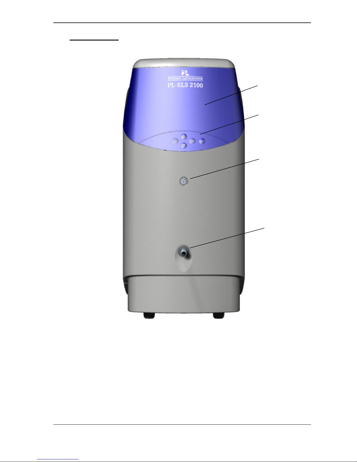
1.6 Connections
Figure 1.1 Front View of PL-ELS 2100/2100 Ice
1. Waste Outlet 2. Eluent Inlet
3. Keypad 4. Graphical Display
2
1
3
4

Chapter 1 –General Information
Document # 6/26069I 6
Version 1.5 May 2006 PL -ELS 2100/2100 Ice Operator’s Manual
Figure 1.2 Rear View of PL-ELS 2100/2100 Ice
1. Fuses
2. Mains input
3. Mai ns switch
4. Connector control I/O –15 pin D
type female
5. Control Firmware flash upgrade
connector
6. Serial RS232 connector- 24bit
digital output
7. Detector output-1V
8. External Vapour Sensor
9. Panel Lock
10. Exhaust port
11. Supply gas inlet
1
2
3
4 5 6 7 8 9 10 11

Chapter 1 –General Information
Document # 6/26069I
Version 1.5 Revision May 2006 PL -ELS 2100/2100 Ice Operator’s Manual
7
1.7 Power Connections
♦ Before conne cting the power cable, ensure the instrument voltage rating matches your local power
supply.
♦ Use only a supply with protective grounding.
♦ The correct fuses should be installed.
For 115V (AC) or 230V (AC) use two 250V H 2A T fuses
This unit is double - fused.
RISK OF FIRE, REPLACE FUSES AS MARKED!
♦ If the voltage rating and fuses are correct for your power source, connect the power cable.
1.8 Extraction
The PL-ELS 2100/2100 Ice is provided with tubing for venting the exhaust gases and vapours, and so
does not need to be placed in a fume cupboard. Instead, the exhaust hose provided must be attached to
the rear of the unit and vented to a fume hood or other disposal unit. Ensure the exhaust hose has an
upward slope from the PL-ELS 2100/2100 Ice so that any condensed solvent is collected in the waste
bottle at the front of the unit and to prevent it accumulating in the tubing.
The exhaust must be extracted to a suitable fume extraction system
ATTENTION
!
WARNING
!
ATTENTION
!
Chapter 1 –General Information
Document # 6/26069I
Version 1.5 Revision May 2006 PL -ELS 2100/2100 Ice Operator’s Manual
8
1.9 Connections
Control I/O connector
The PL-ELS 2100/2100 Ice can be connected to auxiliary equipment to pause or stop the operation of
a pump or autosampler if the PL-ELS 2100/2100 Ice reports an error condition.
The PL-ELS 2100/2100 Ice is equipped with 2 normally-open contact closures and 2 TTL logic
interfaces; one active low and one active high.
The PL-ELS 2100/2100 Ice can be auto-zeroed remotely.
Table 1.1: Control I/O connector
I/O Description Pin No.
Outputs User contact closure – normally open 4 & 12
Pump stop contact closure – normally
open
3 & 10
Pump stop - TTL Active low 2 & ground
Pump stop - TTL Active high 9 & ground
Ground (to case) 1, 5, 6 ,11
Inputs Remote A/Z 7 & ground [firmware version
1.0.15. Units with serial # 004-161 and
before will also require a wiring
modification on the main PCB]
The instrument is supplied with a connector for the I/O socket in order to make appropriate
connections; however, a cable can be purchased for this from Polymer Laboratories (Part # 0860-
0055).
Serial RS232 Connector
The PL-ELS 2100/2100 Ice is fitted with a standard RS232 (DTE-DCE) 3-wire serial interface.
The serial RS232 connector provides a 24bit (10Hz) digital output for connection to a chromatographic
acquisition device.
The PL-ELS 2100/2100 Ice can also be controlled from a PC using the RS232 interface and the PL-
ELS 2100/2100 Ice graphical control software from Polymer Laboratories Ltd. Refer to the control
software online manual for the operating instructions. If controlling the instrument from a PC with a serial
port or USB port is required. If the USB port is used a serial to USB adapter is also required (0860-
0620).
NOTE
!
Pump stop facility must be employed if instrument is to
be left unattended, or if units are stacked

Chapter 1 –General Information
Document # 6/26069I
Version 1.5 Revision May 2006 PL -ELS 2100/2100 Ice Operator’s Manual
9
Gas Connection
The instrument should be supplied with clean, dry nitrogen gas at a minimum head pressure of 60psi. A
4mm push-in connector is provided at the rear of the instrument for a convenient connection to the gas
source.
To prevent against unnecessary gas usage, an automatic but controlled gas shut off valve is integrated
into the gas inlet manifold. This will only allow gas to pass into the instrument when the instrument is
operating. Should the instrument default to a standby mode the gas valve will close.
NOTE
!
The gas inlet valve will be closed when the instrument is first powered
on, and will only open once the instrument is set to RUN mode
Fluid Connection
The eluent from the chromatography system is connected to the front of the instrument via the low dead
volume Valco bulkhead connector provided.
Use only Valco fittings
The liquid inlet port is connected directly to the nebuliser by a short length (190mm) of capillary tube
giving a delay volume from port to nebuliser tip of ~5µl.
1.10 Precautions
Extraction
For correct operation and optimum performance of the PL-ELS 2100/2100 Ice, the unit must be
vented to a fume hood or other means of vapour disposal using the exhaust hose provided. The exhaust
hose should be routed upwards to allow condensed solvent to collect in the waste bottle at the front of
the instrument.
Condensed solvent may be retained in the exhaust hose, be careful not to spill
this solvent when removing the ducting from the rear of the instrument
There is no fire risk within the instrument itself, as electrical components and supply are quite separate
from the evaporation chamber – the risk arises on escape of fumes into the open laboratory. Also, if
fumes are allowed to circulate within the working environment, then they could be harmful to operators
and to sensitive equipment within the laboratory. Judicious use of the exhaust hose provided and careful
disposal of fumes will prevent any problems.
ATTENTION
!
ATTENTION
!
 Loading...