


Polytel®
Data Transmission System
USER MANUAL
Version: R
Polymap Wireless
310 S. Williams Blvd. Ste. 346
Tucson, Arizona 85711

Polytel® Data Transmission System
Table of Contents
1 INTRODUCTION......................................................................................................................................... 4
1.1 SYSTEM OVERVIEW ................................................................................................................................. 4
1.2 INTENDED USE AND USER ........................................................................................................................ 4
2 SYSTEM COMPONENTS AND ACCESSORIES.................................................................................... 4
2.1 PWA-08-01 ACCESS POINT ..................................................................................................................... 5
2.2 REMOTE ACCESSORIES ............................................................................................................................. 5
2.3 PWR-08-01 REMOTE ............................................................................................................................... 6
2.4 PWR-08-02 REMOTE ............................................................................................................................... 6
2.5 PWR-08-03.............................................................................................................................................. 6
3 IDENTIFICATION OF MAJOR PARTS .................................................................................................. 7
4 OPERATING INSTRUCTIONS ................................................................................................................. 9
4.1 INSTALLATION AND SETUP ....................................................................................................................... 9
4.2 LOCATION OF DEVICES ............................................................................................................................. 9
4.3 A NOTE ON TELEPHONE LINES ................................................................................................................ 10
4.4 BATTERIES FOR THE PWR-08-03 ........................................................................................................... 10
4.5 USAGE OF PWA-08-01 ACCESS POINT................................................................................................... 10
4.6 INDICATOR LIGHT ON PWR-08-03 ......................................................................................................... 11
4.7 RETRY SCHEDULE .................................................................................................................................. 11
4.8 OPERATION IN FRANCE, SPAIN OR JAPAN............................................................................................... 11
4.9 TROUBLESHOOTING ............................................................................................................................... 12
4.9.1 PWA-08-01 Access Point............................................................................................................... 12
4.9.2 PWR-08-03 accessory ................................................................................................................... 13
5 SAFETY INFORMATION........................................................................................................................ 13
5.1 PATIENT SAFETY.................................................................................................................................... 13
5.2 ELECTRICAL SAFETY.............................................................................................................................. 14
5.3 COMPLIANCE INFORMATION .................................................................................................................. 14
5.3.1 Compliance Requirements............................................................................................................. 14
5.3.2 Compliance Statement................................................................................................................... 14
5.4 LABEL DEPICTIONS AND LOCATIONS ...................................................................................................... 15
5.4.1 Label locations .............................................................................................................................. 15
5.4.2 Nameplate and Symbols ................................................................................................................ 16
6 OPERATOR MAINTENANCE ................................................................................................................ 18
6.1 VISUAL INSPECTION ............................................................................................................................... 18
6.2 CLEANING YOUR PWA-08-01 AND PWR-08-03: ................................................................................... 18
7 TECHNICAL SPECIFICATIONS ........................................................................................................... 19
7.1 ELECTRICAL INPUT REQUIREMENTS....................................................................................................... 19
7.1.1 PWA-08-01 Access Point............................................................................................................... 19
7.1.2 PWR-08-03.................................................................................................................................... 19
7.1.3 PWR-08-01 and PWR-08-02 ......................................................................................................... 19
7.2 OPERATING AND STORING YOUR ACCESS POINT AND ACCESSORIES ...................................................... 19
CONSULT WITH YOUR LOCAL GARBAGE DISPOSAL AGENCY TO DISPOSE OF USED BATTERIES ..................... 19
7.3 ELECTROMAGNETIC COMPATIBILITY ..................................................................................................... 19
7.4 SYSTEM AVAILABILITY.......................................................................................................................... 20
7.5 DIMENSIONS OF YOUR PWA-08-01 ACCESS POINT................................................................................ 20
7.6 DIMENSIONS OF YOUR PWR-08-03 ACCESSORY: ................................................................................... 20
8 TRADEMARKS.......................................................................................................................................... 20
8-1500-R - 2 -

Polytel® Data Transmission System
APPENDIX I: IEC 60601 SECTION 6........................................................................................................ 21
8.1 PWA-08-01 ACCESS POINT ................................................................................................................... 21
8.2 PWR-08-0X REMOTE UNITS................................................................................................................... 24
8-1500-R - 3 -

Polytel® Data Transmission System
1 Introduction
1.1 System Overview
The Polytel® Data Transmission system is designed to allow patients with chronic
conditions to be monitored remotely. It consists of a series of wireless medical devices, an
Access Point designed to forward data to the data center, and of a monitoring service.
The PWA-08-01 is an Access Point, or “hub” that collects information from medical
devices in the home and forwards them over a regular telephone line.
The PWR-08-01 and PWR-08-02 are accessories that are incorporated into various host
devices, providing a simple way for a host to transmit its data wirelessly to a receiving
station.
The PWR-08-03 is an in-pouch accessory that provides a simple way for host device to
transmit its data wirelessly to a receiving station, allowing remote recording or monitoring
of host values.
When a measurement is taken on a compatible medical device, the radio module
automatically retrieves the new measurement and tries to forward it to the Access Point.
Should that Access Point be unreachable or unavailable, it will periodically retry the
transmission, and eventually shut itself down automatically.
1.2 Intended Use and User
The Polytel® system is intended to be used for the home monitoring of the values of
various host devices. Typical applications include remote monitoring of glucose levels in
diabetic patients, or monitoring of weight and BP in congestive heart failure patients.
The devices are intended to be operated by patients in their homes.
NOTE: Polymap Wireless is not responsible for the measurement, diagnosis,
or electrical safety of the Host Medical Devices. The Polytel® System is a Data
Transmission System only.
2 System components and accessories
The Polytel
01-2) designed to connect to the Mains, Access Point (designated the PWA-08-01),
designed to gather data transmitted from the different Polytel
located either inside of or attached to different medical devices (“Authorized
Applications”).
®
System consists of an AC Adapter (Designated PWA-08-01-1 and PWA-08-
®
Remote units (accessories)
8-1500-R - 4 -
Polytel® Data Transmission System
Polytel PWR-08-01-xxxxx
Remote Board
Polytel PWR-08-02-xxxxx
Remote Board
Polytel PWR-08-03-xxxxx
Remote Board
Polytel
PWA-08-01
Access Point
AC Adapter
PWA-08-01-1 or
PWA-08-01-2
Polytel PWR-08-01-xxxxx
Remote Board
Modem
Telephone Line
Polytel PWR-08-01-xxxxx
Remote Board
Polytel PWA-08-03-xxxxx
Remote Board
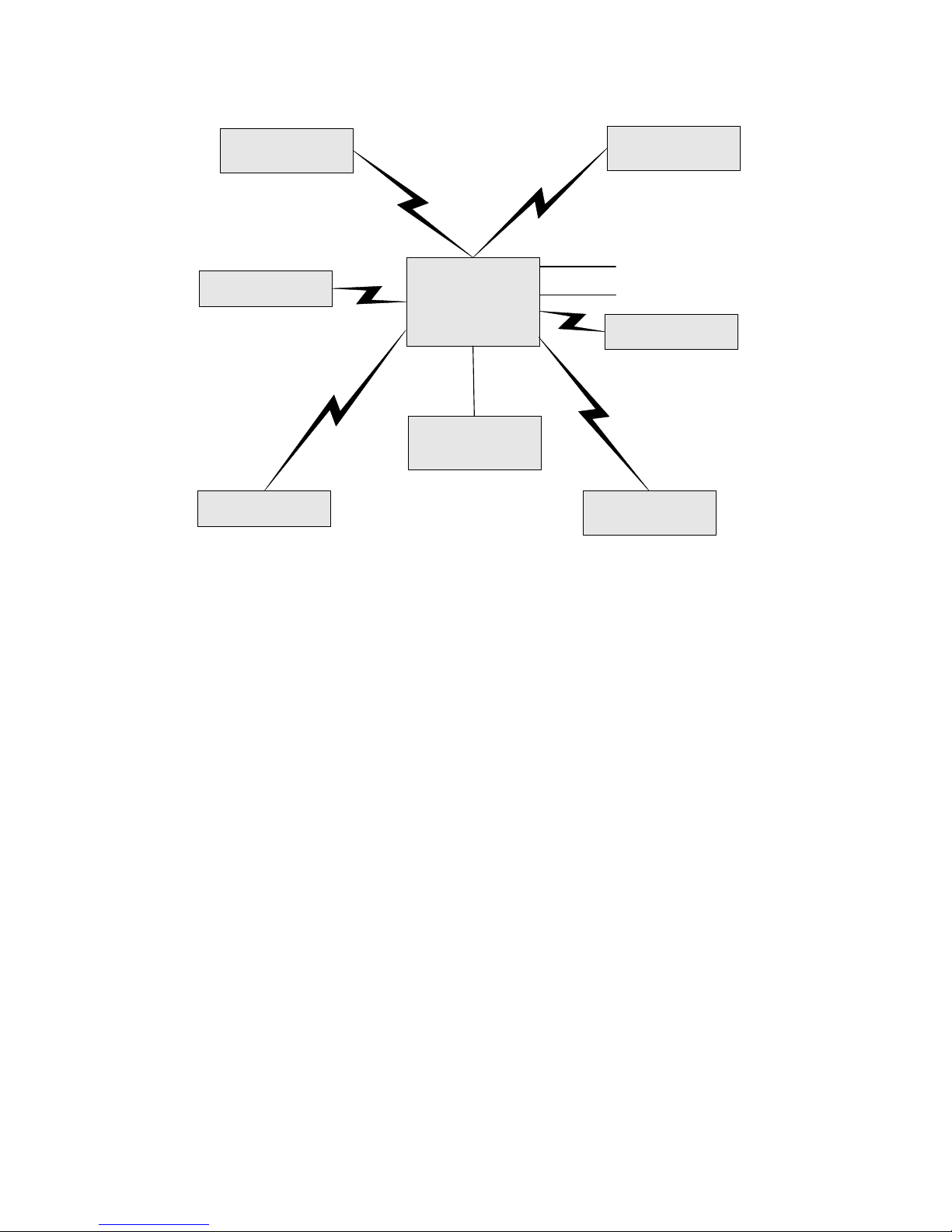
Figure 1: Polytel
®
Data Transmission System Block Diagram: The core of the System is the Access
Point connected to the Mains through an AC Adapter and connected to the telephone line and Modem,
with different accessories (Remote Boards) communicating with the Access Point through radio signal.
The Remote boards are either inside of or cabled to various medical devices
2.1 PWA-08-01 Access Point
This represents the central component of the Polytel® Data Transmission System, and is
used to gather data from all of the accessories. It is pictured in Figure 2.
2.2 Remote accessories
All the system accessories are built around the PWR-08 Remote module. Three different
hardware configurations exist, the PWR-08-01 (board with no case, no battery, onboard
antenna) the PWR-08-02 (board with no case, no battery, external antenna), and the PWR08-03 (which includes an onboard antenna, a case and a battery and incorporates special
circuitry to interface with a host). The individual accessories differ mainly in what
software is loaded on them.
8-1500-R - 5 -

Polytel® Data Transmission System
2.3 PWR-08-01 Remote
This accessory has an onboard antenna (see Figure 2), and is incorporated into hosts by
device manufacturers.
2.4 PWR-08-02 Remote
This accessory is incorporated into hosts by device manufacturers; it incorporates an
external patch antenna for use in hosts that have metal shielding.
2.5 PWR-08-03
This accessory consists of a circuit board in a plastic housing intended to hold two
batteries. The unit (Pictured in Figure 2) is designed to be connected by its cable to a host.
8-1500-R - 6 -

Polytel® Data Transmission System
3 Identification of major parts
PWA-08-01-1 AC Adapter
Polytel® PWA-08-01 Access Point Polytel® PWR-08-01 module
Polytel® PWR-08-02 module with
antenna
Figure 2: Polytel
components.
®
System
Polytel
®
PWR-08-03 accessory
The Access Point is powered by an AC Adaptor connected to the Mains Outlet, and is also
connected to the household telephone line.
®
The Polytel
Data Transmission System consists of an Access Point (Figure 2), which acts
as the “hub” or collector of information from one or more medical devices.
The PWR-08-03 accessory has a visible LED indicator, as shown in figure 3.
8-1500-R - 7 -

Polytel® Data Transmission System
Figure 3: Please note the small indicator light located near the bottom right corner of the back side of
the device. This allows the user to confirm whether the device is operating correctly
Figure 4: Indicator lights on PWA-08-01 Access Point. Leftmost indicates power, then Radio, Modem,
and Error.
Figure 5: back side of PWA-08-01. This shows the power connector on the left, and the two
(interchangeable) telephone connectors to the right.
Symbols:
8-1500-R - 8 -
Meaning
DC Input (6V)
Modem
Telephone line

Polytel® Data Transmission System
4 Operating Instructions
4.1 Installation and setup
The effective radio range of the Access Point and the matching medical devices is around
330 feet (100 meters). Please choose a location in your house that is centrally located, or
close to where the measuring devices will be used.
CAUTION – To reduce the risk of explosion or fire do not use this
equipment in presence of flammable Anaesthetic mixture with Air or with
Oxygen or Nitrous Oxide.
1) Connect a telephone cord between the Access Point and a telephone jack on the
wall. An extra telephone outlet is provided on the back of the Access Point so you
can plug a telephone into the same outlet.
2) CAUTION – To reduce the risk of fire, use only No. 26 AWG or larger
telecommunication line cord.
3) Connect the 6VDC power to the back of the unit, and plug the AC Adapter into a
regular AC outlet. When the device is connected, expect all the front-panel LEDs
to light momentarily, with the leftmost (Power) LED remaining on, and the 2nd
LED (Radio) blinking at roughly one-second intervals (see Figure 4).
4) To mount the unit on the wall (OPTIONAL), two screws, mounted horizontally, on
1.5” (37mm) centers, can be used. Please use screws and anchoring systems
appropriate to the wall material. The screw head size should be between ¼” and
3/8” (5-9 mm).
4.2 Location of devices
For successful use of the system, it is vital to remember that at its core, the Polytel Data
Transmission System is wireless. This means that the transmitting device must be
located within radio range of the Access Point, normally 330 feet. Note that various
types of physical barriers, including walls, can reduce the effective range of the
devices. The variety of construction methods makes predicting the effective range in a
particular setting difficult.
Do not place Access Point on a metal surface or in a metal enclosure as
this is likely to interfere with correct operation.
FCC Radiation Exposure Statement: This equipment complies with FCC
radiation exposure limits set forth for an uncontrolled environment. This equipment
should be installed and operated with minimum distance 20 cm between the
equipment and your body. This transmitter must not be co-located or operating in
conjunction with any other antenna or transmitter.
8-1500-R - 9 -

Polytel® Data Transmission System
A good rule of thumb is that the access point should be located either in the same or an
adjacent room to that where the measuring device is located. You can confirm that the
devices are working together correctly by looking for the blinking light patterns on the
access point to change within a minute after a measurement.
4.3 A note on telephone lines
The PWA-08-01 Access Point is designed to operate over “regular” or traditional telephone
lines. If you use a Voice over IP (VoIP) provider for your telephone service, you must
confirm with your provider that “fax and modem support” is enabled for the telephone line
you intend to use. VoIP service quality varies widely, and Polymap Wireless cannot
guarantee that the device will operate correctly with every type of VoIP line.
NOTE: this device is not designed for connection to digital PBX systems, such as might be
found in an office.
4.4 Batteries for the PWR-08-03
The PWR-08-03 accessory is powered by two lithium cells (CR2 size). To open the battery
compartment, slide the lid in the direction indicated by the arrow labeled “OPEN” on the
lid, and allow the lid to open. Please insert each battery with the negative side (–) down and
its positive end (+) up, as shown in figure 6. If the two negative ends or the two positive
ends of the batteries touch one another, the device will not operate. A set of batteries is
expected to last several months. To close the battery compartment, bring the lid gently
down against the batteries, and slide it in the direction opposite the “OPEN” arrow until the
lid stops.
4.5 Usage of PWA-08-01 Access Point
In normal use, there is no intervention required by the user. Nonetheless, indicator lights
are provided to give the user some sense of the correct operation of the device. There are
four indicator lights on the front panel of the Access Point. These are, respectively:
POWER, RADIO, TELEPHONE, and ERROR (see figure 4)
POWER (Green) Always on in normal operation
RADIO (Green) Blinks roughly once per second, more blinking while data is being
received
TELEPHONE
(Green)
ERROR (Red) Comes on when data was received by the Access Point but not
Blinks when the device is connecting to the server to transfer its
data. Solid while the device is connected and transferring data
(usually only a few seconds)
successfully transferred to the data center. This will occur, for
example, when the telephone is in use, or there is some other
congestion on the network. The Access point will keep trying,
every few minutes, until it succeeds in transferring the data. Note
that the forty most recent measurements are stored until they are
transmitted.
A rapidly flashing red light indicates that the telephone cord is not
8-1500-R - 10 -

Polytel® Data Transmission System
correctly connected.
In normal operation, the leftmost, or POWER light, will remain on, and the second light
(RADIO), will blink roughly once per second. During the data transfer, the RADIO light
will blink in other patterns. The PHONE light is used to indicate usage of the telephone,
and the ERROR light is used to indicate a data transfer error.
Note that data transfer errors are expected to occur when phone lines or the network are
congested, and should not be a concern unless they persist for more than one hour. Should
the error light persist for more than an hour, please contact the agency that provided you
with this equipment.
If the ERROR light comes on the first time the device is used, the most likely
explanation is that it is not correctly connected to a telephone jack.
4.6 Indicator light on PWR-08-03
The device contains a small LED. This indicator will light shortly after you take a
measurement on the host. It will turn itself off completely after the data is successfully
transmitted. Should the data fail to transmit immediately, the device will schedule multiple
retries, and the light will come on again several times for short intervals.
LED Meaning
Solid (maximum 20 seconds) Retrieving data from host
Fast blink (1 per second) Looking for a receiver
Very fast blink (2 per second) Transmitting data
Slow blink (1 every 10 seconds) Waiting for a retry (previous attempt did not find
receiver)
4.7 Retry Schedule
Immediately after a new measurement is taken, the unit will attempt to contact the receiver
or access point. Should this fail, it will retry after waiting for one minute. Failing that, it
will wait two minutes before retrying. Should all of these transmission attempts fail, the
measurement will be stored and the device will turn itself off automatically. Stored
measurements are time stamped and transmitted along with the next measurement.
If you know you have measurements stored and not yet transmitted, you can wake up the
device and transmit the stored measurements without taking a new measurement. Please
consult the documentation of each device for specifics instructions on how to do this.
4.8 Operation in France, Spain or Japan
The device uses a frequency hopping protocol in the 2.4GHz band. Some of the channels
used are not allowed in France, though they are allowed elsewhere. Please notify Polymap
Wireless of your intent to use the device in this country so that it can be reconfigured
appropriately.
8-1500-R - 11 -

Polytel® Data Transmission System
4.9 Troubleshooting
4.9.1 PWA-08-01 Access Point
The PWA-08-01 Access Point incorporates a red “ERROR” LED. This light indicates that
the device has received data from a measuring device but has not yet been able to transmit
it. This failure may be a normal occurrence (the phone number the unit dialed was busy
and it’s waiting to try again) or it may indicate a failure that requires user interaction.
Note that Access Points will try repeatedly to deliver the data they are holding until they
are successful.
The process of troubleshooting the operation of an Access Point involves being able to
watch the colored LEDs on its front panel. Troubleshooting can be made significantly
easier if an ordinary telephone is plugged into the second telephone jack, allowing you to
listen to the operation of the device.
Error Cause Corrective Action
Red LED
flashes
several times
immediately
after
measurement
Solid red
LED after
measurement
Solid red
LED after
measurement
Solid red
LED after
measurement
Solid red PBX or VoIP If you hear a modem
No dialtone Replace telephone cord
or check telephone
outlet
Bad
telephone
jack or cord
Plug a telephone into 2nd
jack of Access Point.
Hang up. Unplug power
cord to AP and plug it in
again. Wait until
modem light (3rd green
light) comes on, then
pick up telephone and
listen. If you don’t a
dialtone, check cord or
telephone outlet
Defective AP Follow instructions
above. If you hear a
dialtone but do not hear
a telephone number
being dialed, the AP
needs to be replaced.
Busy signal If this happens
repeatedly, there may be
a telephone company
issue with 800 number
access. Remove power
from AP and dial 1-800420-6565 from the
telephone.
8-1500-R - 12 -

Polytel® Data Transmission System
LED after
measurement
Solid red
LED after
measurement
line answer (this sounds like
a fax machine), the
problem may be due to
your telephone line. If
you have VoIP service,
ensure that “fax and
modem support” is
selected.
Server-side
configuration
issues
If none of the above
helps resolve your issue,
please contact your
service provider. A
number of different
service-side errors can
lead to the data being
retained on the Access
Point.
4.9.2 PWR-08-03 accessory
Error Cause Corrective Action
LED
does not
light
LED
does not
light
No “PC”
indicated
on host
No “PC”
indicated
on host
No “PC”
indicated
on host
No “PC”
indicated
on host
Batteries
missing or
low
Cable not
connected to
host
Batteries
missing or
low
Cable not
connected to
host
Cable not
firmly
plugged into
host
Cable frayed If visual inspection
Replace batteries
Connect cable to host
Replace batteries
Connect cable to host
Plug cable firmly into
host
shows cable is frayed,
unit must be repaired
5 Safety Information
5.1 Patient Safety
Warnings and Cautions
8-1500-R - 13 -

Polytel® Data Transmission System
WARNING: “Modifications made to the product, unless expressly approved
by Polymap Wireless, LLC could void the user’s license for and the warranty of the
device.”
CAUTION: Risk of explosion if battery is replaced by an incorrect type.
Dispose of used batteries according to the instructions.
5.2 Electrical Safety
Only authorized maintenance staff may remove the covers from the PWR-08-03 Remote
Device. Always refer servicing to Polymap Wireless-authorized personnel.
The Polytel® Data Transmission System is classified as CLASS II equipment as per
IEC60601-1 and Class II Medical Devices per 21CFR. There are no patient connected
parts in the Polytel® Data Transmission System. The Host Medical Devices are approved
for use by their respective manufacturers and agencies monitoring them. Polymap
Wireless is not responsible for their diagnostic accuracy or their electrical safety. There are
no special provisions to protect the system from flammable anesthetics or ingress of liquids
WARNING! Never operate this device in zones where there is a risk of
explosion. Electrical equipment used in the presence of flammable anesthetics or
oxygen may cause an explosion.
5.3 Compliance Information
This section details the telemetry system compliance requirements and the manufacturer’s
responsibilities.
5.3.1 Compliance Requirements
The manufacturer is responsible for the effects of safety, reliability, and performance of
this equipment with the following provisions:
• The equipment is used in accordance with instructions for use
• Assembly operations, extensions, modifications, or repairs are performed by
authorized persons only.
5.3.2 Compliance Statement
The manufacturer states that this device conforms to:
• FDA 21 CFR Parts 820
• IEC 60601-1: Medical Electrical Equipment – General Requirements for Safety.
• IEC 60601-1-1: Medical Electrical Equipment – Collateral standard: Safety
requirements for medical electrical systems
• IEC 60601-1-2: Medical Electrical Equipment – Collateral standard:
Electromagnetic compatibility for medical electrical systems
8-1500-R - 14 -

Polytel® Data Transmission System
• IEC 60601-1-4: Medical Electrical Equipment – Collateral standard: Programmable
medical electrical systems
• UL 60601: Medical Electrical Equipment, Part 1 – General Requirements for Safety
• CSA: Medical Electrical Equipment, Part 1: C22.2601 No. 601.1 – M9 – General
Requirements for Safety
• The manufacturer of this device complied with the following requirements
applicable at time of manufacture:
o ISO 13485:2003
o ISO 13485/8 under Canadian Medical Device Conformity Assessment
System (CMDCAS)
5.4 Label depictions and Locations
5.4.1 Label locations
Label on 120V power supply Label on 230V power supply
Label on PWA-08-01 PWR-08-01 label
PWR-08-02 label PWR-08-03 label
Figure 6 Label locations
8-1500-R - 15 -

Polytel® Data Transmission System
v
5.4.2 Nameplate and Symbols
Model:
PWA-08-01-1
RoHS 2002/95/EC
Assembled USA
Date of Manufacture:
Input: 120V~, 60Hz, 14VA
Output: 6V ---, 1.0A
IEC/EN/UL/CAN/CSA
60601-1 60601-1-2
S/N:
Model:
PWA-08-01-2
RoHS 2002/95/EC
Assembled USA
Date of Manufacture:
IEC/EN/UL/CAN/CSA
60601-1 60601-1-2
S/N:
Input: 230V~, 50Hz, 14VA
Output: 6V ---, 1.0A
Label for 120V power supply Label for 230V power supply
The label on the bottom of The Access Point PWA-08-01 or PWR-08-03 shows the unique radio ID of the de
This label also shows the seals that denote the principal regulatory approvals :
Model: PWA-08-01
RoHS 2002/95/EC
This device complies with part 15 of the FCC Rules.
Operation is subject to the following two conditions:
(1) This device may not cause harmful interference,
and (2) this device must accept any interference
received, including interference that may cause
undesired operation.
Manufactured in USA
Date of Manufacture:
FCC ID:QYPPWA0801
ICES-003-B/ NMB-003B
IC: 4552A-PWA0801
6V 1000mA
IEC/EN/UL/CAN/CSA
60601-1 60601-1-2
S/N:
Label for PWA-08-01 Access Point
8-1500-R - 16 -
Polytel® Data Transmission System
IEC/EN/UL/CAN/CSA 60601-1
Model: PWR-08-03
FCC ID: QYPPWR0801
IC: 4552A-PWR0801
Use two CR2 Lithium batteries
60601-1-2
Assembled in USA
Mfg Date:
S/N:
Label for PWR-08-03 accessory
IEC/EN/UL/CAN/CSA 60601-1
Model: PWR-08-01
FCC ID: QYPPWR0801
IC: 4552A-PWR0801
60601-1-2
Assembled in USA
Mfg Date:
S/N:
Label for PWR-08-01 wireless module
IEC/EN/UL/CAN/CSA 60601-1
Model: PWR-08-02
FCC ID: QYPPWR0801
IC: 4552A-PWR0801
60601-1-2
Assembled in USA
Mfg Date:
S/N:
Label for PWR-08-02 Wireless Module
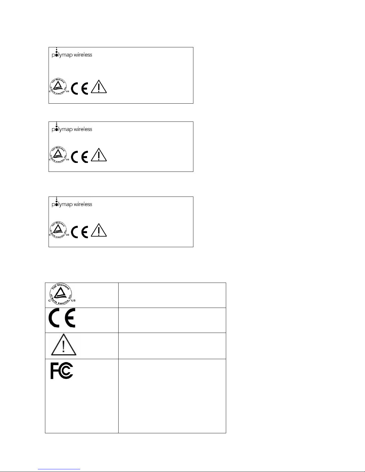
Figure 7: Labels.
Indicates that the device was tested
to comply with the US and
Canadian safety directives.
Indicates that the device was tested
to comply with the CE MDD
directive.
Indicates that you should read
accompanying documents before
use.
This device complies with part 15
of the FCC Rules. Operation is
subject to the following two
conditions:
(1) This device may not cause
harmful interference, and
(2) this device must accept any
interference received, including
interference that may cause
8-1500-R - 17 -

Polytel® Data Transmission System
undesired operation.
Indicates Class II equipment under
the IEC 60601-1 safety standard
Indicates that the transformer
IEC/UL/CAN/CSA
60601-1 60601-1-2
FCC: QYPPWR0801 Indicates the FCC listing numbers
IC: 4552A-PWR0801 Indicates the Industry Canada
S/N Serial number
incorporates a fuse designed to
protect against temperatures in
excess of 130°C
Indicates that the device complies
with both the safety and the radio
requirements of these respective
standards
for the device
listing numbers for the device
6 Operator Maintenance
6.1 Visual Inspection
The user should perform a periodic inspection (once a month) of the system to identify any
component that may have become damaged or is not performing correctly.
WARNING: All parts of this System are repairable. The Repair of any
damaged or incorrectly operating item should be performed ONLY by
Polymap Wireless authorized personnel!
Contact Polymap Wireless promptly to maintain the equipment in the safest possible
condition.
Specific attention should be paid to the cable used to connect the unit with the host.
6.2 Cleaning your PWA-08-01 and PWR-08-03:
These units should be cleaned once a year. The batteries in the PWR-08-03 should be
replaced once in 6 months. Take the following steps:
1. Disconnect your PWR-08-03 from its host before cleaning.
2. Remove the batteries from your PWR-08-03, or disconnect the PWA-08-01 from
the power outlet
3. Never use any spray on your units. Sprays may penetrate the unit and damage the
internal electronic components.
4. Dampen a soft cloth with water, or a weak solution of household dishwashing liquid
mixed with water, and wipe the unit.
5. Never immerse your units in any liquid.
6. Insert the batteries after cleaning the unit and reconnect your PWR-08-03 to its
host, or reconnect your PWA-08-01 to the wall outlet, as appropriate.
.
8-1500-R - 18 -

Polytel® Data Transmission System
7 Technical Specifications
7.1 Electrical Input Requirements
7.1.1 PWA-08-01 Access Point
The PWA-08-01 is powered by an AC adapter. Two different adapters are available:
• 120V~ 60Hz, PWA-08-01-1
• 230V~ 50Hz. PWA-08-01-2
Both configurations have the same output rating:
6VDC, 1000ma (Maximum power, 6VA)
WARNING: There is an additional Power source inside the Access Point:
3V Lithium Battery.
7.1.2 PWR-08-03
The PWR-08-03 is powered by two CR2 Lithium cells in series (3V each). Max. Power
consumption: 1W
7.1.3 PWR-08-01 and PWR-08-02
These remote boards are powered from their Host devices.
Input Voltage: 5VDC
Input current: 180mA max
Max Power consumption: 0.9W
7.2 Operating and Storing your Access Point and accessories
WARNING: Remove batteries from the equipment if not intending to use
for more than 3 months!
Consult with your local Garbage Disposal Agency to dispose of used batteries
The recommended operating temperatures for your units are 10° to 40° Celsius (50° to
104° Fahrenheit).
The recommended storage temperatures are -40° to +70° Celsius (-40° to 158° Fahrenheit).
If you move your devices from a cold location to a warm location, please allow it to come
up to room temperature before powering it on.
The equipment can be shipped via commercial transportation (Air and land) in packaging
designed for this purpose. The recommended transportation temperatures are -40° to +70°
Celsius (-40° to 158° Fahrenheit). Altitude:10,000m
7.3 Electromagnetic Compatibility
Like other electrical medical equipment, the PWA-08-01, PWR-08-01, PWR-08-02, PWR08-03 units require special precautions to ensure electromagnetic compatibility with other
8-1500-R - 19 -

Polytel® Data Transmission System
electrical medical devices. To ensure electromagnetic compatibility (EMC) the device
must be installed and operated according to the information provided in this manual.
NOTE: the entire Polytel® Data Transmission System wit all its components has been
tested to comply with IEC 60601-1-2:2001 requirements for EMC with other devices.
NOTE: This equipment has been tested and found to comply with the limits for a Class B
digital device , pursuant to Part 15 of the FCC Rules. These limits are designed to provide
reasonable protection against harmful interference in a residential installation. This
equipment generates, uses, and can radiate radio frequency energy and, if not installed and
used in accordance with the instructions, may cause harmful interference to radio
communications. However, there is no guarantee that interference will not occur in a
particular installation. If this equipment does cause harmful interference to radio or
television reception, which can be determined by turning the equipment off and on, the user
is encouraged to try and correct the interference by one or more of the following measures:
• Reorient or locate the receiving antenna.
• Increase the separation between the equipment and receiver.
• Connect the equipment into an outlet on a circuit different from that to which the
receiver is connected.
• Consult the dealer or an experienced radio/TV technician for help.
7.4 System Availability
The PWR-08-03 is designed to attempt delivery of each measurement from the host for
several minutes after a measurement is taken. The system is immediately available to
retrieve additional measurements in the case where they are taken before the previous
measurement(s) have been transmitted.
The PWA-08-01 Access Point is always available to receive measurements from measuring
devices, and will store them until it is able to forward them to your service provider
7.5 Dimensions of your PWA-08-01 Access Point
144mm x 97mm x 27mm (5.67 inches x 3.81 inches x 1.06 inches
7.6 Dimensions of your PWR-08-03 accessory:
72mm x 20mm x 45mm (2.85 inches x 0.8 inches x 1.8 inches)
8 Trademarks
Bluetooth® word mark and logos are owned by the Bluetooth SIG, Inc.
Polytel
This product was designed solely by Polymap Wireless, independent of any of the host
device manufacturers
®
is a registered trademark of Polymap Wireless LLC.
8-1500-R - 20 -

Polytel® Data Transmission System
Appendix I: IEC 60601 Section 6
8.1 PWA-08-01 Access Point
8-1500-R - 21 -

Polytel® Data Transmission System
8-1500-R - 22 -

Polytel® Data Transmission System
8-1500-R - 23 -

Polytel® Data Transmission System
8.2 PWR-08-0x Remote units
8-1500-R - 24 -

Polytel® Data Transmission System
8-1500-R - 25 -

Polytel® Data Transmission System
8-1500-R - 26 -

Polytel® Data Transmission System
Index
Access Point, 4
Availability, 20
Batteries, 19
Inserting, 10
Blink. See Indicator
Cautions, 13
Cleaning, 18
Communications Hub, 4
Compliance, 14
Devices
Cleaning, 18
Electrical Safety, 14
Electromagnetic compatibility, 19
EMC, 19
France, operation in, 11
Hub, Communications, 4
Indicator light, 11
Indicator Lights, 7, 8
Installation, 9
Labels, 16, 17
LEDs, 7, 8
Light
Indicator, 11
Lights, Indicator, 7, 8
Location of devices, 9
Metal enclosure, 9
Metal surface, 9
Nameplate, 16
Operation in France, 11
Patient Safety, 13
PBX lines, 10
Power Brick, 19
Regulatory Compliance, 14
Retries, 11
Safety, Electrical, 14
Safety, Patient, 13
Setup, 9
Symbols, 16
Telephone Cord, 9
Telephone lines, 10
Temperature
Operating, 19
Trademarks, 20
Troubleshooting, 12, 13
Voice over IP lines, 10
VoIP, 10
Wall Adapter, 19
Warnings, 13
8-1500-R - 27 -
 Loading...