

Polymap Wireless Polytel, PWA-08-01 User Manual

Polytel®
Data Transmission System
USER MANUAL
Version: R
Polymap Wireless
310 S. Williams Blvd. Ste. 346
Tucson, Arizona 85711

Polytel® Data Transmission System
Table of Contents
1 INTRODUCTION......................................................................................................................................... 4
1.1 SYSTEM OVERVIEW ................................................................................................................................. 4
1.2 INTENDED USE AND USER ........................................................................................................................ 4
2 SYSTEM COMPONENTS AND ACCESSORIES.................................................................................... 4
2.1 PWA-08-01 ACCESS POINT ..................................................................................................................... 5
2.2 REMOTE ACCESSORIES ............................................................................................................................. 5
2.3 PWR-08-01 REMOTE ............................................................................................................................... 6
2.4 PWR-08-02 REMOTE ............................................................................................................................... 6
2.5 PWR-08-03.............................................................................................................................................. 6
3 IDENTIFICATION OF MAJOR PARTS .................................................................................................. 7
4 OPERATING INSTRUCTIONS ................................................................................................................. 9
4.1 INSTALLATION AND SETUP ....................................................................................................................... 9
4.2 LOCATION OF DEVICES ............................................................................................................................. 9
4.3 A NOTE ON TELEPHONE LINES ................................................................................................................ 10
4.4 BATTERIES FOR THE PWR-08-03 ........................................................................................................... 10
4.5 USAGE OF PWA-08-01 ACCESS POINT................................................................................................... 10
4.6 INDICATOR LIGHT ON PWR-08-03 ......................................................................................................... 11
4.7 RETRY SCHEDULE .................................................................................................................................. 11
4.8 OPERATION IN FRANCE, SPAIN OR JAPAN............................................................................................... 11
4.9 TROUBLESHOOTING ............................................................................................................................... 12
4.9.1 PWA-08-01 Access Point............................................................................................................... 12
4.9.2 PWR-08-03 accessory ................................................................................................................... 13
5 SAFETY INFORMATION........................................................................................................................ 13
5.1 PATIENT SAFETY.................................................................................................................................... 13
5.2 ELECTRICAL SAFETY.............................................................................................................................. 14
5.3 COMPLIANCE INFORMATION .................................................................................................................. 14
5.3.1 Compliance Requirements............................................................................................................. 14
5.3.2 Compliance Statement................................................................................................................... 14
5.4 LABEL DEPICTIONS AND LOCATIONS ...................................................................................................... 15
5.4.1 Label locations .............................................................................................................................. 15
5.4.2 Nameplate and Symbols ................................................................................................................ 16
6 OPERATOR MAINTENANCE ................................................................................................................ 18
6.1 VISUAL INSPECTION ............................................................................................................................... 18
6.2 CLEANING YOUR PWA-08-01 AND PWR-08-03: ................................................................................... 18
7 TECHNICAL SPECIFICATIONS ........................................................................................................... 19
7.1 ELECTRICAL INPUT REQUIREMENTS....................................................................................................... 19
7.1.1 PWA-08-01 Access Point............................................................................................................... 19
7.1.2 PWR-08-03.................................................................................................................................... 19
7.1.3 PWR-08-01 and PWR-08-02 ......................................................................................................... 19
7.2 OPERATING AND STORING YOUR ACCESS POINT AND ACCESSORIES ...................................................... 19
CONSULT WITH YOUR LOCAL GARBAGE DISPOSAL AGENCY TO DISPOSE OF USED BATTERIES ..................... 19
7.3 ELECTROMAGNETIC COMPATIBILITY ..................................................................................................... 19
7.4 SYSTEM AVAILABILITY.......................................................................................................................... 20
7.5 DIMENSIONS OF YOUR PWA-08-01 ACCESS POINT................................................................................ 20
7.6 DIMENSIONS OF YOUR PWR-08-03 ACCESSORY: ................................................................................... 20
8 TRADEMARKS.......................................................................................................................................... 20
8-1500-R - 2 -

Polytel® Data Transmission System
APPENDIX I: IEC 60601 SECTION 6........................................................................................................ 21
8.1 PWA-08-01 ACCESS POINT ................................................................................................................... 21
8.2 PWR-08-0X REMOTE UNITS................................................................................................................... 24
8-1500-R - 3 -

Polytel® Data Transmission System
1 Introduction
1.1 System Overview
The Polytel® Data Transmission system is designed to allow patients with chronic
conditions to be monitored remotely. It consists of a series of wireless medical devices, an
Access Point designed to forward data to the data center, and of a monitoring service.
The PWA-08-01 is an Access Point, or “hub” that collects information from medical
devices in the home and forwards them over a regular telephone line.
The PWR-08-01 and PWR-08-02 are accessories that are incorporated into various host
devices, providing a simple way for a host to transmit its data wirelessly to a receiving
station.
The PWR-08-03 is an in-pouch accessory that provides a simple way for host device to
transmit its data wirelessly to a receiving station, allowing remote recording or monitoring
of host values.
When a measurement is taken on a compatible medical device, the radio module
automatically retrieves the new measurement and tries to forward it to the Access Point.
Should that Access Point be unreachable or unavailable, it will periodically retry the
transmission, and eventually shut itself down automatically.
1.2 Intended Use and User
The Polytel® system is intended to be used for the home monitoring of the values of
various host devices. Typical applications include remote monitoring of glucose levels in
diabetic patients, or monitoring of weight and BP in congestive heart failure patients.
The devices are intended to be operated by patients in their homes.
NOTE: Polymap Wireless is not responsible for the measurement, diagnosis,
or electrical safety of the Host Medical Devices. The Polytel® System is a Data
Transmission System only.
2 System components and accessories
The Polytel
01-2) designed to connect to the Mains, Access Point (designated the PWA-08-01),
designed to gather data transmitted from the different Polytel
located either inside of or attached to different medical devices (“Authorized
Applications”).
®
System consists of an AC Adapter (Designated PWA-08-01-1 and PWA-08-
®
Remote units (accessories)
8-1500-R - 4 -
Polytel® Data Transmission System
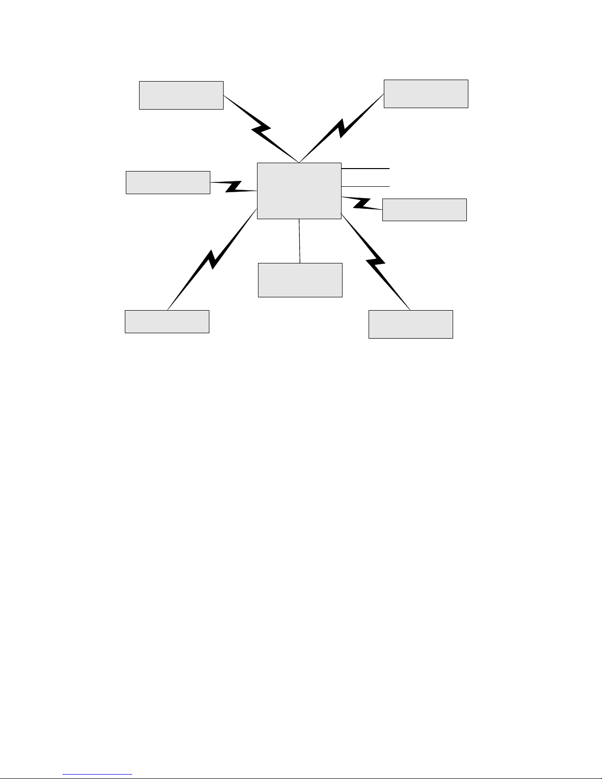
Polytel PWR-08-01-xxxxx
Remote Board
Polytel PWR-08-02-xxxxx
Remote Board
Polytel PWR-08-03-xxxxx
Remote Board
Polytel
PWA-08-01
Access Point
AC Adapter
PWA-08-01-1 or
PWA-08-01-2
Polytel PWR-08-01-xxxxx
Remote Board
Modem
Telephone Line
Polytel PWR-08-01-xxxxx
Remote Board
Polytel PWA-08-03-xxxxx
Remote Board
Figure 1: Polytel
®
Data Transmission System Block Diagram: The core of the System is the Access
Point connected to the Mains through an AC Adapter and connected to the telephone line and Modem,
with different accessories (Remote Boards) communicating with the Access Point through radio signal.
The Remote boards are either inside of or cabled to various medical devices
2.1 PWA-08-01 Access Point
This represents the central component of the Polytel® Data Transmission System, and is
used to gather data from all of the accessories. It is pictured in Figure 2.
2.2 Remote accessories
All the system accessories are built around the PWR-08 Remote module. Three different
hardware configurations exist, the PWR-08-01 (board with no case, no battery, onboard
antenna) the PWR-08-02 (board with no case, no battery, external antenna), and the PWR08-03 (which includes an onboard antenna, a case and a battery and incorporates special
circuitry to interface with a host). The individual accessories differ mainly in what
software is loaded on them.
8-1500-R - 5 -

Polytel® Data Transmission System
2.3 PWR-08-01 Remote
This accessory has an onboard antenna (see Figure 2), and is incorporated into hosts by
device manufacturers.
2.4 PWR-08-02 Remote
This accessory is incorporated into hosts by device manufacturers; it incorporates an
external patch antenna for use in hosts that have metal shielding.
2.5 PWR-08-03
This accessory consists of a circuit board in a plastic housing intended to hold two
batteries. The unit (Pictured in Figure 2) is designed to be connected by its cable to a host.
8-1500-R - 6 -

Polytel® Data Transmission System
3 Identification of major parts
PWA-08-01-1 AC Adapter
Polytel® PWA-08-01 Access Point Polytel® PWR-08-01 module
Polytel® PWR-08-02 module with
antenna
Figure 2: Polytel
components.
®
System
Polytel
®
PWR-08-03 accessory
The Access Point is powered by an AC Adaptor connected to the Mains Outlet, and is also
connected to the household telephone line.
®
The Polytel
Data Transmission System consists of an Access Point (Figure 2), which acts
as the “hub” or collector of information from one or more medical devices.
The PWR-08-03 accessory has a visible LED indicator, as shown in figure 3.
8-1500-R - 7 -

Polytel® Data Transmission System
Figure 3: Please note the small indicator light located near the bottom right corner of the back side of
the device. This allows the user to confirm whether the device is operating correctly
Figure 4: Indicator lights on PWA-08-01 Access Point. Leftmost indicates power, then Radio, Modem,
and Error.
Figure 5: back side of PWA-08-01. This shows the power connector on the left, and the two
(interchangeable) telephone connectors to the right.
Symbols:
8-1500-R - 8 -
Meaning
DC Input (6V)
Modem
Telephone line

Polytel® Data Transmission System
4 Operating Instructions
4.1 Installation and setup
The effective radio range of the Access Point and the matching medical devices is around
330 feet (100 meters). Please choose a location in your house that is centrally located, or
close to where the measuring devices will be used.
CAUTION – To reduce the risk of explosion or fire do not use this
equipment in presence of flammable Anaesthetic mixture with Air or with
Oxygen or Nitrous Oxide.
1) Connect a telephone cord between the Access Point and a telephone jack on the
wall. An extra telephone outlet is provided on the back of the Access Point so you
can plug a telephone into the same outlet.
2) CAUTION – To reduce the risk of fire, use only No. 26 AWG or larger
telecommunication line cord.
3) Connect the 6VDC power to the back of the unit, and plug the AC Adapter into a
regular AC outlet. When the device is connected, expect all the front-panel LEDs
to light momentarily, with the leftmost (Power) LED remaining on, and the 2nd
LED (Radio) blinking at roughly one-second intervals (see Figure 4).
4) To mount the unit on the wall (OPTIONAL), two screws, mounted horizontally, on
1.5” (37mm) centers, can be used. Please use screws and anchoring systems
appropriate to the wall material. The screw head size should be between ¼” and
3/8” (5-9 mm).
4.2 Location of devices
For successful use of the system, it is vital to remember that at its core, the Polytel Data
Transmission System is wireless. This means that the transmitting device must be
located within radio range of the Access Point, normally 330 feet. Note that various
types of physical barriers, including walls, can reduce the effective range of the
devices. The variety of construction methods makes predicting the effective range in a
particular setting difficult.
Do not place Access Point on a metal surface or in a metal enclosure as
this is likely to interfere with correct operation.
FCC Radiation Exposure Statement: This equipment complies with FCC
radiation exposure limits set forth for an uncontrolled environment. This equipment
should be installed and operated with minimum distance 20 cm between the
equipment and your body. This transmitter must not be co-located or operating in
conjunction with any other antenna or transmitter.
8-1500-R - 9 -
 Loading...