

Page 1
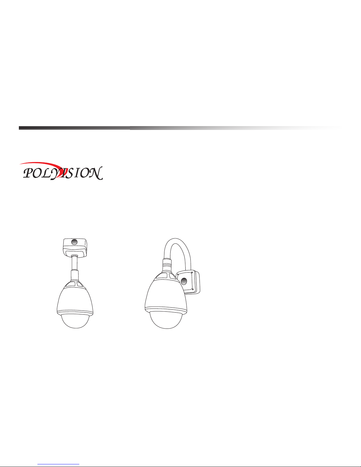
Outdoor High Speed Dome System
User Manual
Page 2

Contents
Before installing
Key features
Configure, fix and wire
Basic speed dome operation
Programming the speed dome
The keyboard shortcuts of speed dome
Parts and dimensions
Wiring schematic
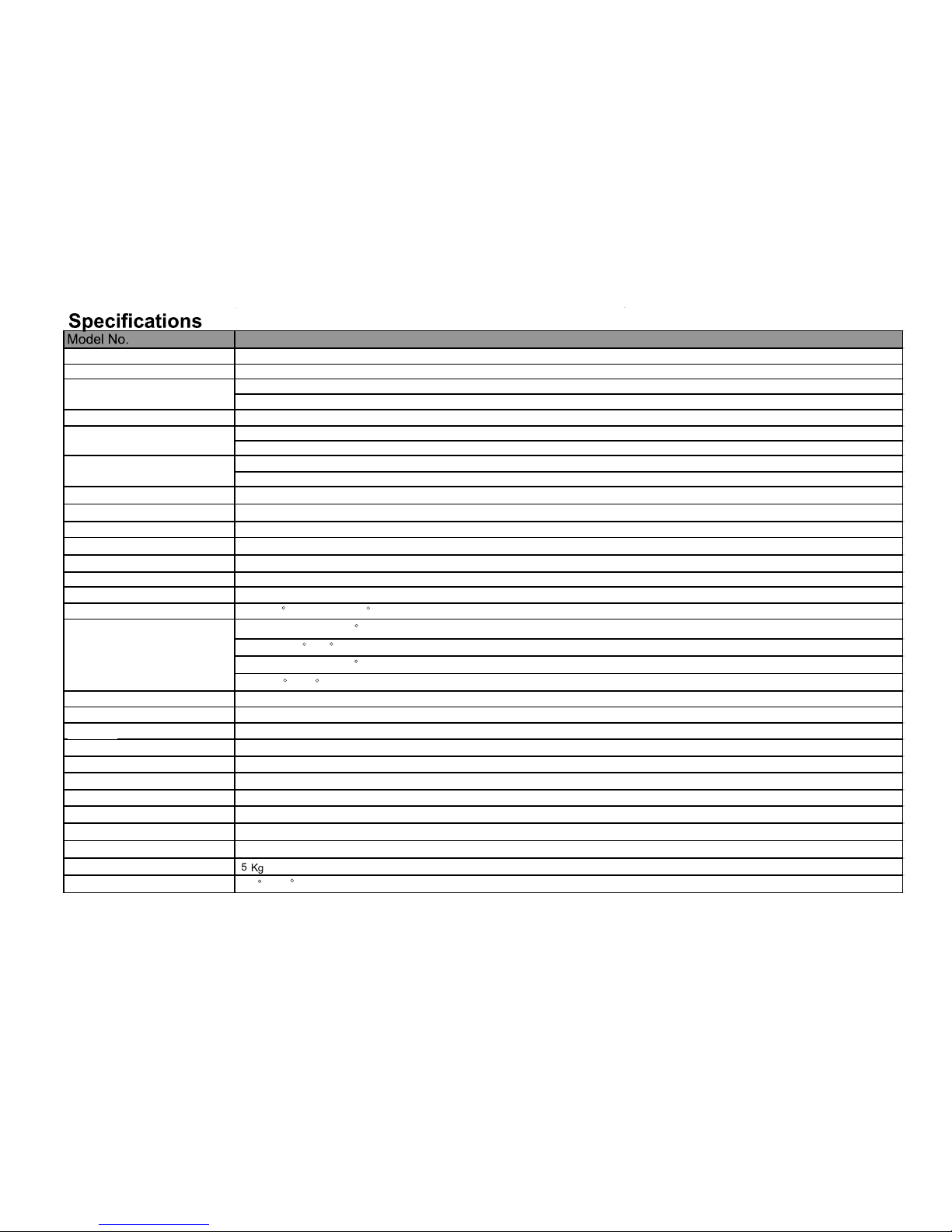
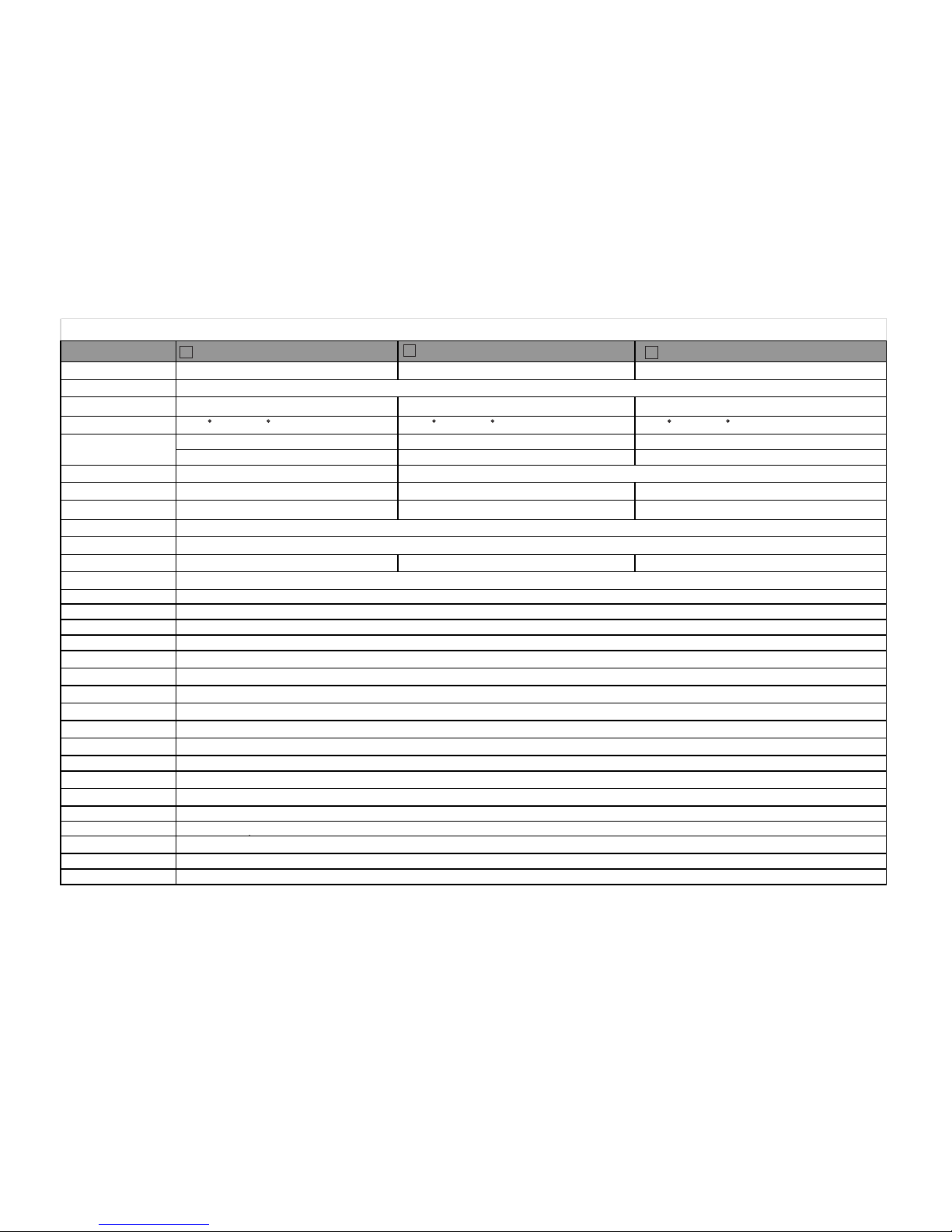
Specifications
1
2
3
5
7
6
16
17
19
Outdoor High Speed Dome System
Appendix Of Outdoor High Speed Dome System
Page 3
Before installing
1
!
·Installation should be carried out only by qualified personnel and in accordance with
any wiring regulations in force at the time.
·The speed dome is heavy and could cause injury if not correctly mounted in
accordance with these instructions. Use only the fittings supplied with the speed
dome and ensure that all lanyard safety cables are connected correctly during
installation.
·Adequate protection against lightning strikes and power surges must be installed to
prevent damage to the speed dome.
·Any safety warnings on the product and in these instructions must be adhered to.
·If cleaning is necessary, disconnect power to the speed dome first. Do not use
abrasive cleaners, as these will cause damage to the cover and cause poor image
quality. Use a damp cloth to gently clean the dome cover and dry off with a soft
clean cloth.
·Do not use any brackets, mounts or other accessories not specifically designed for
use with this speed dome.
·Do not attempt to service or repair the speed dome as opening or removing covers
may expose dangerous voltages or other hazards. Refer all servicing to qualified
service personnel.
Page 4

Key features
2
Presets
Up to 254 sets of positional and zoom level information can be stored as
presets. These can be called manually by the operator, automatically by an
alarm input, or grouped to form a sequence of actions to run automatically.
Each preset can also be programmed with the following:
Alarm action - relay outputs can be triggered when particular presets are
called
Title - each preset can be titled with up to 10 characters so that zones can
easily be identified
Pattern tours
Any dome movement can be recorded - and subsequently played back - as
four separate pattern tours. These can be played back individually or
grouped to form a sequence of tours.
Scan function
Scan is a useful feature when, for example, the operator wishes to ‘patrol’ a
perimeter fence. you can choose any two points to define as start point and
end point , the scan function will smoothly and accurately move from one
end to the other and then back again in a repeating sequence.
Group function
The group function is a powerful feature which allows the operator to define
a sequence of speed dome actions to form an automatic patrol sequence.
Actions can be a mix of preset positions, pattern tours and scan functions.
Up to 8 groups can be defined and each group can have up to 20 actions
which repeat indefinitely until interrupted by the operator or an alarm input.
Specific parameters such as preset speed, dwell time and action loop can
also be specified.
Speed can
be adjusted as necessary and up to 8 scan functions can be defined.
Privacy zones
By defining a privacy zone, sensitive scenes such as windows can be
masked off so they cannot be viewed by the operator. Up to 8 privacy
zones can be defined. Privacy zone size adjusts automatically depending
on the speed dome zoom level.
Alarm inputs and outputs
This speed dome has 8 alarm inputs and 4 alarm outputs. Any alarm input
can be set to call a predefined preset, scan function, pattern or group. Any
preset can be configured to activate any or all of the alarm outputs. For
example, a PIR detector connected to alarm input 1 could call preset 7 to
view that particular scene whilst activating an external lamp connected to
relay 1 and an external siren connected to relay 3.
On Screen Display (OSD)
The operator can choose if any or all of the following information is
displayed on screen during normal speed dome operation.
Preset status and title
Speed dome position coordinates and zoom level
Alarm I/O status
Time and Date
Speed dome ID
The speed dome also has a full on screen menu setup allowing quick and
easy configuration of all the speed dome features.
Powerful park function
The speed dome can be configured to run a specified scan function, pattern
tour, group or preset after a defined period of inactivity.
·
Auto Adapt Power: The speed dome can automatic adapt the power
supply between DC12V~24V and AC12V~24V.
Page 5
Configure, fix and wire
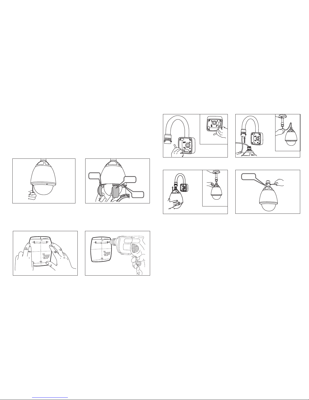
1. Remo ve the foam pack ing pieces
Befo re procee ding with i nstalla ti on, the s pe ed dome f oa m packi ng
piec es must be re moved. Re move the ou te r dome co ve r with th e to ol
supp lied and ca refully r emove the f oa m packi ng p ieces . Wh en
hand ling the do me cover, al ways wear t he gloves s up plied t o av oid
gett ing finge rprints o n th e outer d om e cover.
Foam
Foam
1. Wearing the gloves and using the supplied
tool, remove the outer dome cover.
2. Remove the foam pieces from the camera
module.
Foam
Outdoor High Speed Dome System
2. Fix th e bracket
1. Fix the supplied mounting template, taking
account of any pipework, cables, overhangs
etc. that may obstruct the bracket once fitted.
2. After making suitable checks for buried
pipes and cables, drill fixing holes suitable for
the bolts supplied with the speed dome.
3. Remove the junction box cover. Using the
supplied bolts and tool, firmly fix the bracket.
Pendent option
Pendent option
Pendent option
5. Bring the speed dome up to the bracket.
6. Tighten the three screws to fix the speed
dome and ensure the lanyard safety chain is
properly connected.
4. Feed the speed dome cable through the
bracket.
Lanyard
3
Page 6
3. Wire up the junction box
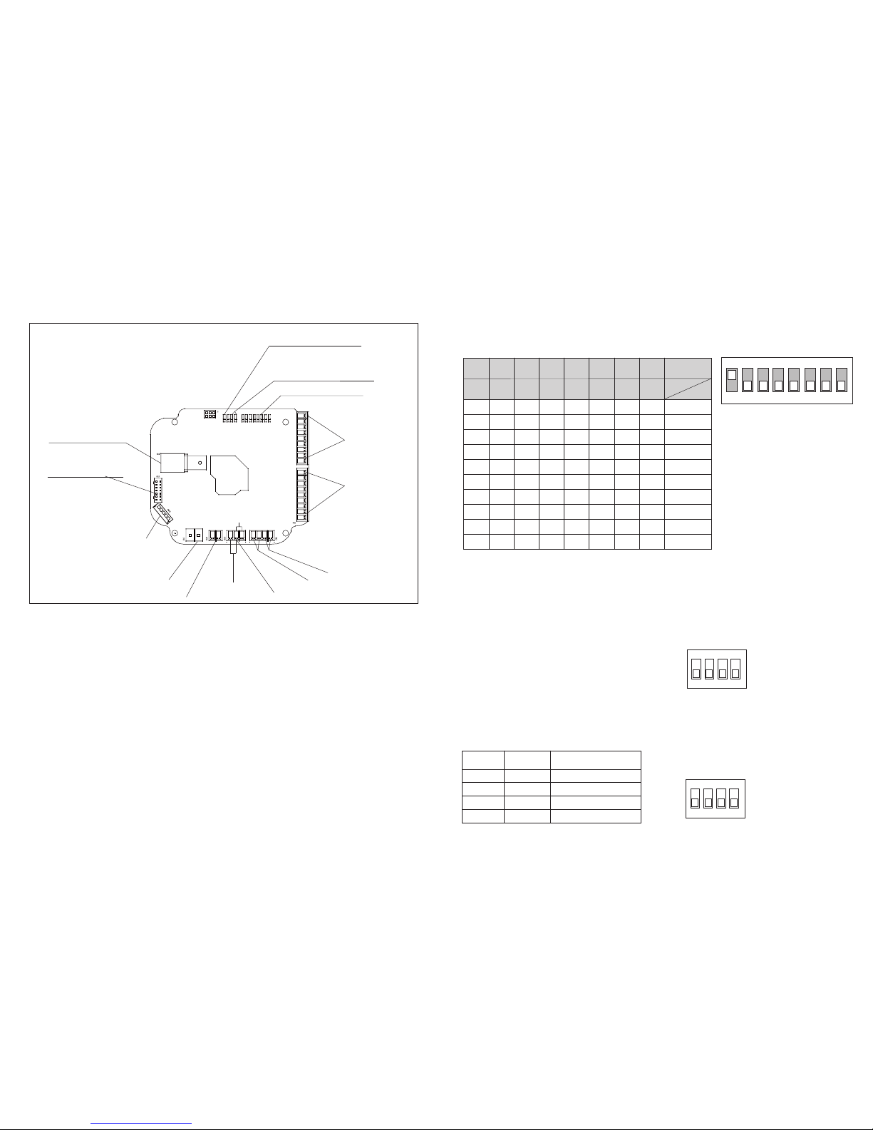
1.Video output
13.ADDRESS ID SWITCH
Junc tion box PC B detail
4.DC 12~AC 24V Power
5.12V DC OUTPUT
6.AUDIO IN
2.SPEED DOME CABLE
8.AUDIO OUT
7.AUDIO GROUND
9.Rs485
10.Rs422
14.BAUD RATE SWITCH
15.RS485/422 SWITCH
12.ALARM INPUT
11.ALARM OUT
3.SPEED DOME CABLE
(1).Video output: Standard 1V P-P,Use good quality 75
Ohm cable terminated with a B NC connec tor.
(2).(3)Speed Dome Cable : the inter face connected with
speed dome.
(4).Auto Adapt Power: this can automatic adapt the
power supply between .DC12V~24V and AC12V~24V
(5).12V DC outpu t: an extra 1 2V DC power i s availab le
for other devices, but plea se be Kindl y noted tha t the
maximum power of the other de vice is 6W an d 500mA.
(6).(7).(8)Audio In/O ut/Ground:standard audio In/Out
interface, thi s functio n is just for I P speed dome(only IP
model has these functions ).
(11).(12).Alarm Input/Output:8 Alarm Inp ut and 4
Outpu t.
(13)Address ID switch:
ON
OFF
ON
ON
ON
ON
OFF
OFF
OFF
---
OFF
ON
ON
OFF
ON
ON
OFF
ON
OFF
---
OFF
OFF
OFF
ON
ON
ON
ON
ON
OFF
---
OFF
OFF
OFF
OFF
OFF
ON
OFF
OFF
ON
---
OFF
OFF
OFF
OFF
OFF
ON
OFF
OFF
OFF
---
OFF
OFF
OFF
OFF
OFF
ON
OFF
OFF
OFF
---
OFF
OFF
OFF
OFF
OFF
ON
OFF
OFF
OFF
---
OFF
OFF
OFF
OFF
OFF
ON
OFF
OFF
OFF
---
1
2
3
5
7
255
4
6
8
-
1
1 2 3 4 5 6 7 8
D I P
2 4 8 1 6 3 2 64 1 2 8
Va l
I D
Note : ID 0 s hould not b e used. Whe re m ultiple s pe ed dome s
are co nn ected, a un ique ID mus t be a ssigned t o each one.
1 2 3 4 5 6 7 8
ON
Fact ory defau lt
swit ch positi ons
Spee d dome ID is se t
usin g standar d
bina ry notati on
(14).(15).Baud rate/R S485/42 2 switch:
1 2 3 4
Factory default switch positions
RS
48
5/
4
22
B
AUD RAT
E
Baud ra te DIP switch table
1 2 3 4
OFF
OFF
ON
OFF
OFF
ON
ON
ON
2400 bp s
4800 bp s
9600 bp s
38400 b ps
P r o t o c o l/ R a t e
3 4
Factory default switch positions
RS485/422 SETUP
The switch number 1
on RS48 5
off Rs422
(9).(10).RS485/422: Using different communication
method according to the RS4 85/422 sw itch.
4
Page 7
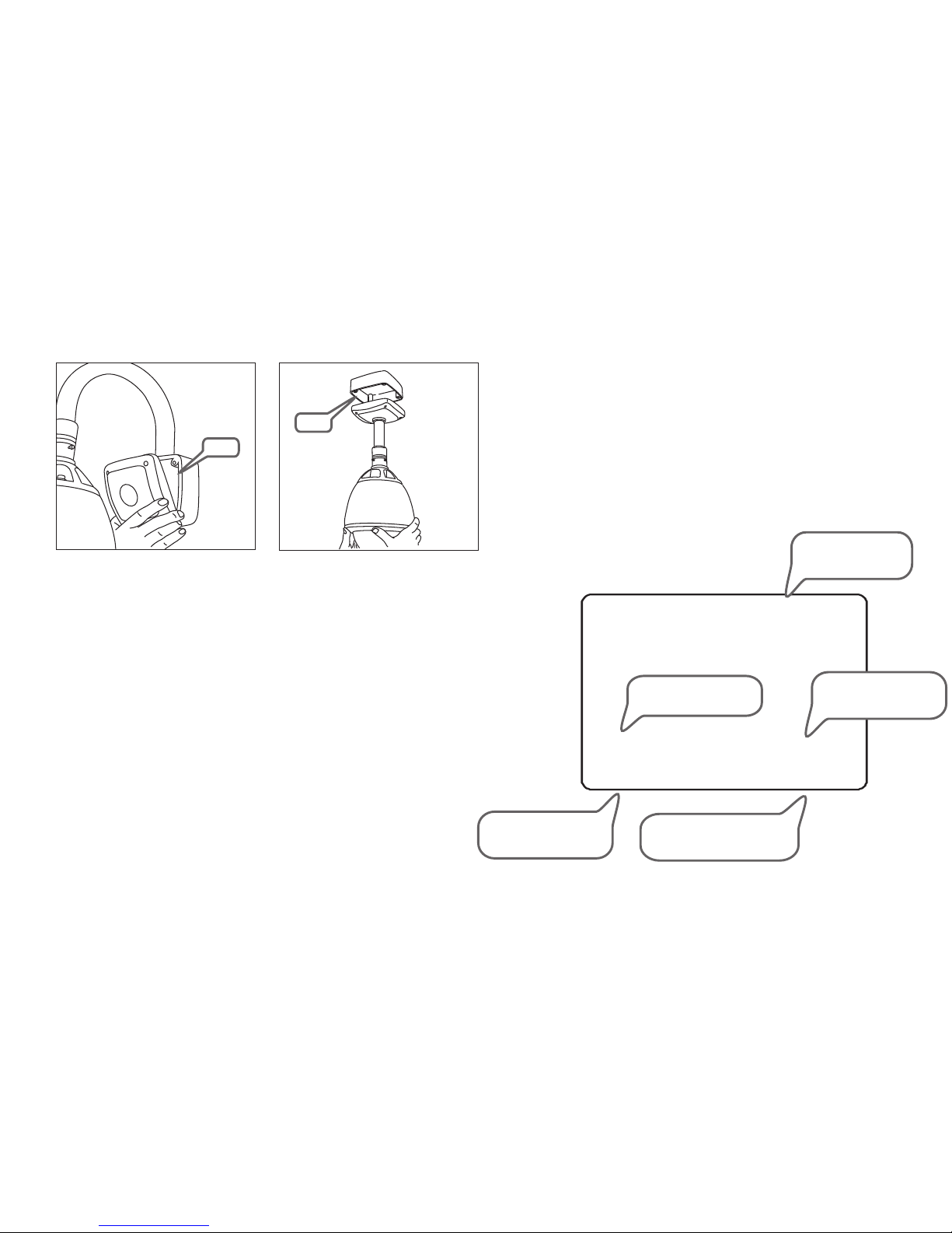
4. Complete the inst all
1a - wall bracket option. After making all the
connections to the PCB, fit the junction box
cover with the four screws.
Note: when fixing the cover to the junction box, ensure that the seal is also
fitted properly and that none of the cables are trapped.
1b - pendent option. After making all the
connections to the PCB, raise the dome
assembly to the junction box, connect the
dome cable to the PCB and fix with the four
screws.
Seal
Seal
5
0 7 / J A N / 2 0 0 7
0 9 : 3 7 : 1 5
C A M 1
O : - 2 3 -
I : 1 2 3 4 5 6 7 8
3 0 7 / 4 6 / x 3
P R E S E T 3R E C E P T I O N
Basic speed dome operation
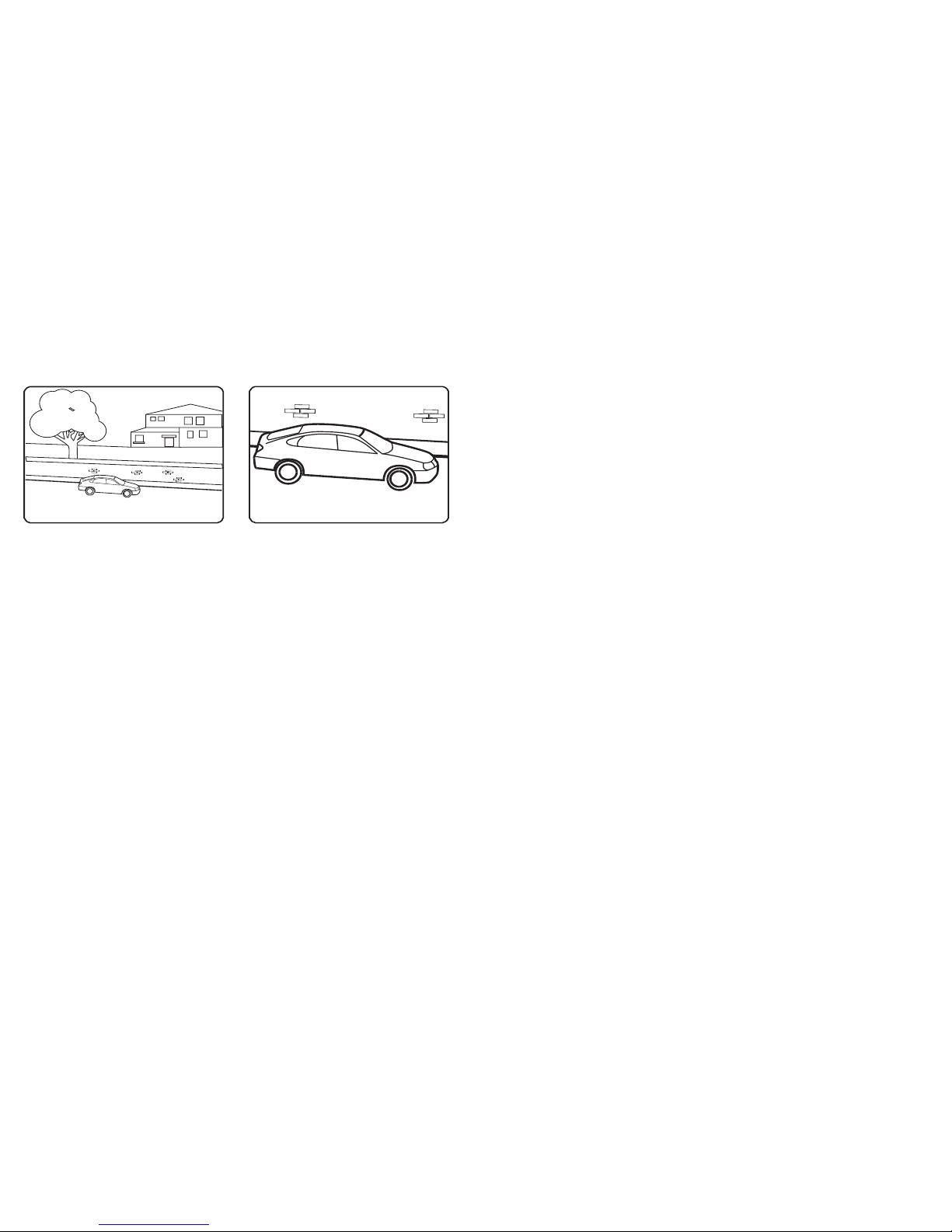
Under standing the O n Screen Displ ay (OSD)
Ther e are many di ff er ent PTZ k ey boards an d DVR syste ms capabl e
of con trollin g this spee d dome, and i t wo uld be im po ssibl e to
desc ribe them a ll here. Ther ef ore, ex am ples give n in the foll owing
page s are based o n the more po pular con tr ol equi pm ent ava il able.
Whil st the prin ciples of o peratio n ar e the sam e, r egard le ss of the
cont rol equip ment used , referen ce m ay need t o be m ade to th e
manu al suppli ed with you r particu lar contr ol e quipm en t.
CAMERA ID: Shows the
current ID as defined by the
dip switch settings
ALARM I/O: Shows which
alarm inputs and outputs are
active
DATE/CLOCK: Shows
current time and date
PTZ INFORMATION: The current
pan/tilt position in degrees and
the current zoom level
ACTION TITLE: Shows
current speed dome
action
Page 8
Preset - 191 - DISPLAY AUTO
Preset - 193 - DISPLAY ON
Preset - 194 - MASK DISPLAY OFF
Preset - 195 - MASK DISPLAY ON
Preset - 190 - Enter switch focus modes among auto,semiauto,manual.
Enter
Enter
Enter
Enter
6
P RES E T 3P ARK I N G B A Y 1
S ET PR E S E T 1
To program a preset position, move the speed
dome to the desired scene and zoom level
and press:
SET - XXX - ENTER
Where XXX is a preset number between 1 &
(but note that preset 95 is reserved and
cannot be used). Confirmation is displayed on
the OSD.
254
To delete a preset position, press:
CLEAR - XXX - ENTER
Where XXX is a preset number between 1 &
(but note that preset 95 is reserved and
cannot be used). The preset position is
cleared from memory.
254
To reprogramme a preset position, follow the
steps for programming a preset - it is not
necessary to delete the old preset position first
To go to a preset position thats already
been programmed, press:
PRESET - XXX - ENTER
Where XXX is a preset number between 1 &
254 (but note that preset 95 is reserved and
cannot be used). The speed dome moves to
the preset position. Confirmation and preset
title (if defined) is displayed on the OSD.
O :-- - -
I :12 3 4 5 6 7 8
3 25/ 3 7 / x 1
O :-- - -
I :12 3 4 5 6 7 8
3 25/ 3 7 / x 3
0 7/J A N / 2 0 0 7
1 2:3 8 : 0 5
C AM 1
0 7/J A N / 2 0 0 7
1 2:4 2 : 2 2
C AM 1
the keyboard shortcuts of speed dome
Once t he patter n tours, sc an and gr oups have b een
prog rammed in t he speed do me setup me nu , they ca n al l be
acce ssed dire ctly from t he P TZ cont ro l equip me nt by usi ng t he
foll owing seq uences.
1. To sta rt a PATT ER N tour pr es s:
PRESE T - 13 X - ENTER
Where X i s a PATTE RN t our num be r betwe en 1 & 4
The sel ec ted PATTERN to ur w ill run i nd efini te ly un ti l a ma nua l mo ve men t is m ad e by th e
opera to r or an ala rm i nput is r ec eived .
2. To sta rt a S CAN fun ct ion, pr es s:
PRESE T - 14 X - ENTER
Where X i s a SC AN func ti on numb er b etwee n 1 & 8
The sel ec ted SCA N fu nctio n wi ll run in de finit el y unt il a m an ual m ov em ent i s ma de b y the
opera to r or an ala rm i nput is r ec eived .
3. To sta rt a g roup, p re ss:
PRESE T - 15 X - ENTER
Where X i s a GR OUP num be r betwe en 1 & 8
The sel ec ted GRO UP w ill run i nd efini te ly unti l a ma nua l mo ve men t is m ad e by th e op er ato r
or an ala rm i nput is r ec eived .
All th e other sho rtcuts pl ea se see be lo w table :
ShutC ut s Fun ct io n
Prese t - 95 - E nter Ca ll O SD Me nu
Prese t - 17 1 - Enter C al l WDR
Prese t - 17 3 - Enter C al l Auto Whi te Bal an ce
Prese t - 17 4 - Enter C al l Brigh tn ess
Prese t - 17 5 - Enter C al l Digit al S low S hu tt er
Prese t - 17 6 - Enter C al l DNR
Prese t - 17 7 - Enter C al l Jog Max S pe ed
Prese t - 17 9 - Enter C al l High Li gh t Con tr ol
Prese t - 18 0 - Enter C al l Day/N ig ht
func tions
First, we assume your keybo ard using k ey PRESET to
call preset.
Page 9
Displ ay setup
Syste m informatio n
The sp eed dome se tup menu al lows the op er ator to c us tomis e an d
prog ram all asp ects of spe ed dome ope ra tion. Al l me nu sett in gs are
reta ined in non -volati le memory s o if p ower is l os t to the sp ee d dome
for an y reason, a ll settin gs w ill be re ta ined.
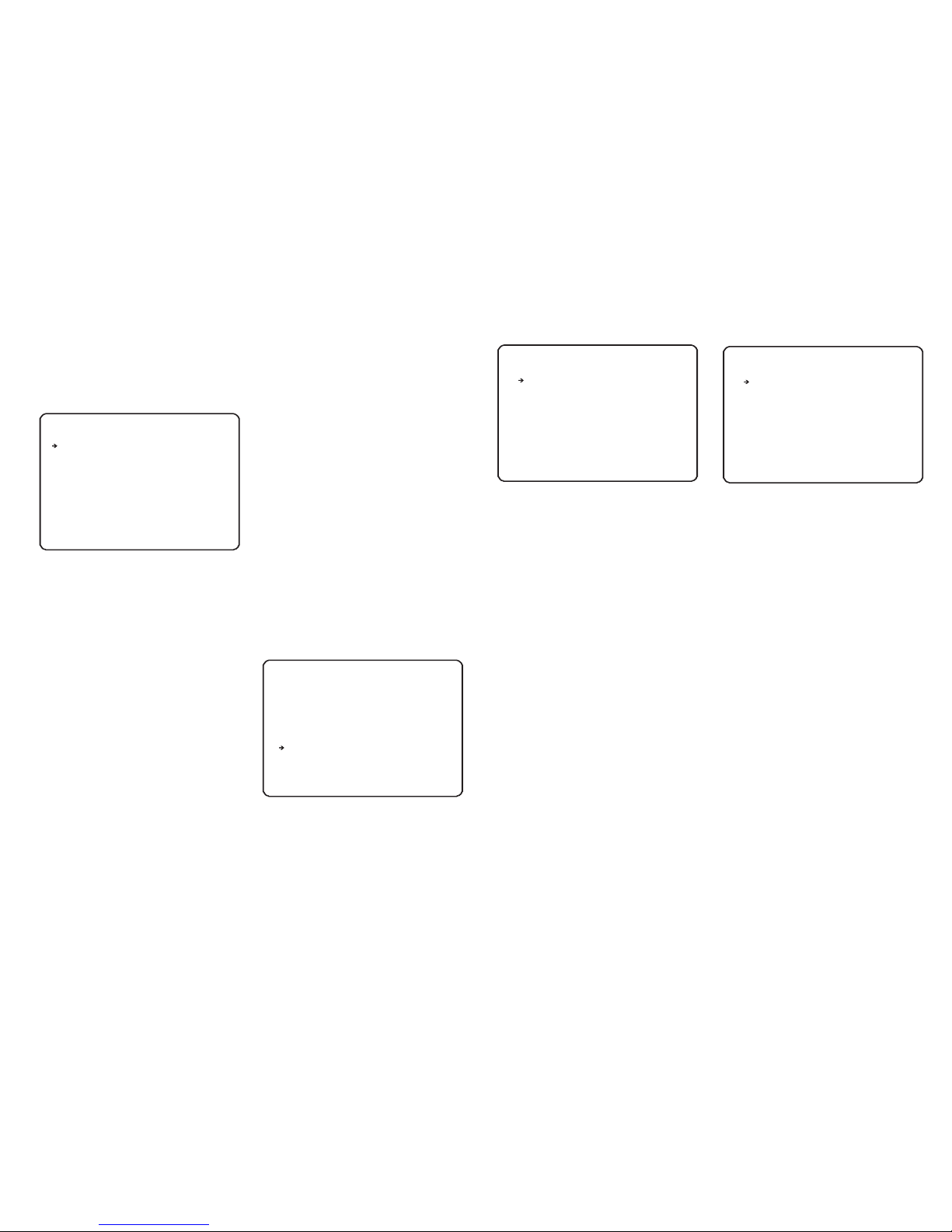
RO O T M E NU
-- - - - -- - - -- - - -- - - - -- - - -- - - -- -
<S Y S T EM I N F OR M A TI O N >
<D I S P LA Y S E TU P >
<M O T I ON S E T UP >
<C A M E RA S E T UP >
<F U N C TI O N S ET U P >
<S Y S T EM S E T UP >
<H E L P >
EX I T
DIS PLAY SETU P
--- ----- ----- ----- ----- ----- -
CAM ERA ID
PTZ I NFORM ATI ON
ACTI ON TITL E
PRE SET LAB EL
ALAR M I/O
DATE /TI ME
<PR IVACY ZON E>
BAC K
EXI T
SY S T E M IN F O RM A T IO N
-- - - - -- - - -- - - -- - - - -- - - -- - - -- -
FIR MWARE VE R
COL OUR SYS TEM
PRO TOCOL
BAU D RATE
ADD RES S
BAC K
EXI T
To access the speed dome setup menu, key:
SHOT - 95 - ENTER
To navigate the main menu, move the joystick
up / down to choose a menu item or change
settings within a menu item.
To enter a menu item or confirm a new setting,
key: NEAR
To exit a menu item or cancel a new setting,
key: FAR
Where a menu item is surrounded by
brackets, it indicates that there is a sub menu.
Where a menu screen shows EXIT, selecting
this option will exit the menu and the speed
dome will return to normal operation. Where a
menu screen shows BACK, selecting this
option will return to the higher menu level.
The main menu has seven options:
<SYSTEM INFORMATION> - Provides
information such as firmware version, protocol
and ID values as defined by the dip switch
settings.
<DISPLAY SETUP> - Allows the operator to
specify which On Screen Display information
is shown during normal operation. Also allows
privacy zones to be defined.
<MOTION SETUP> - Set the general
functions of pan/tilt motion, for example,
preset lock, power up action, auto flip and jog
speed etc.
<CAMERA SETUP> - Allows all operating
features of the speed dome to be programmed
and managed. Also allows settings for the
camera module to be changed
<FUNCTION SETUP> - Set the Preset/Scan/
Pattern/Group/Schedule function.
<SYSTEM SETUP> - Allows various speed
dome settings to be reset to factory defaults
Shows information and current configuration.
From the main menu, use the joystick to
highlight SYSTEM INFORMATION and key:
NEAR
To return to the main menu, highlight BACK
and key: NEAR
To exit the setup menu completely, highlight
EXIT and key: NEAR
From the main menu, use the joystick to
highlight DISPLAY SETUP and key: NEAR
CAMERA ID (ON / OFF) - shows camera ID
according to the DIP switch settings, eg
CAM 1.
PTZ INFORMATION (ON / OFF / AUTO) shows the current pan / tilt position in degrees
and the current zoom level.
ACTION TITLE (ON / OFF / AUTO) - shows
current speed dome action, eg PRESET3.
PRESET LABEL (ON / OFF / AUTO) - shows
preset title (if defined) when a preset is called.
ALARM I/O (ON/OFF) - shows real time
status of the alarm inputs and outputs.
DATE/TIME(ON/OFF) -show date and time
<PRIVACY ZONE> - sub menu to setup the
speed dome privacy zones
Highlight the item to modify and key: NEAR
Use the joystick to change the setting and key:
NEAR to save or: FAR to cancel.
Note: If the auto option is chosen, the relevant
information is displayed for a few seconds
before disappearing.
4.0 1W36
PAL
AUTO
240 0
1
ON
AUT O
AUT O
AUT O
ON
ON
7
Programming the speed dome
Priva cy zone
PRI VAC Y ZO NE
-- - - - -- - - -- - - -- - - - -- - - -- - - -- -
MAS K NO.
DIS PLAY
CLE AR
<ED IT MASK >
BAC K
EXI T
From the display setup menu, use the joystick
to highlight PRIVACY ZONE and key: NEAR
ZONE NO. (1-8) - shows the privacy zone
currently being modified.
DISPLAY - determines whether the privacy
zone is displayed during normal operation.
<EDIT ZONE> - allows the operator to define
the privacy zone.
Highlight the item to modify and key: NEAR
Use the joystick to change the setting and key:
NEAR to save or: FAR to cancel.
1
OF F
CL E A R
Page 10
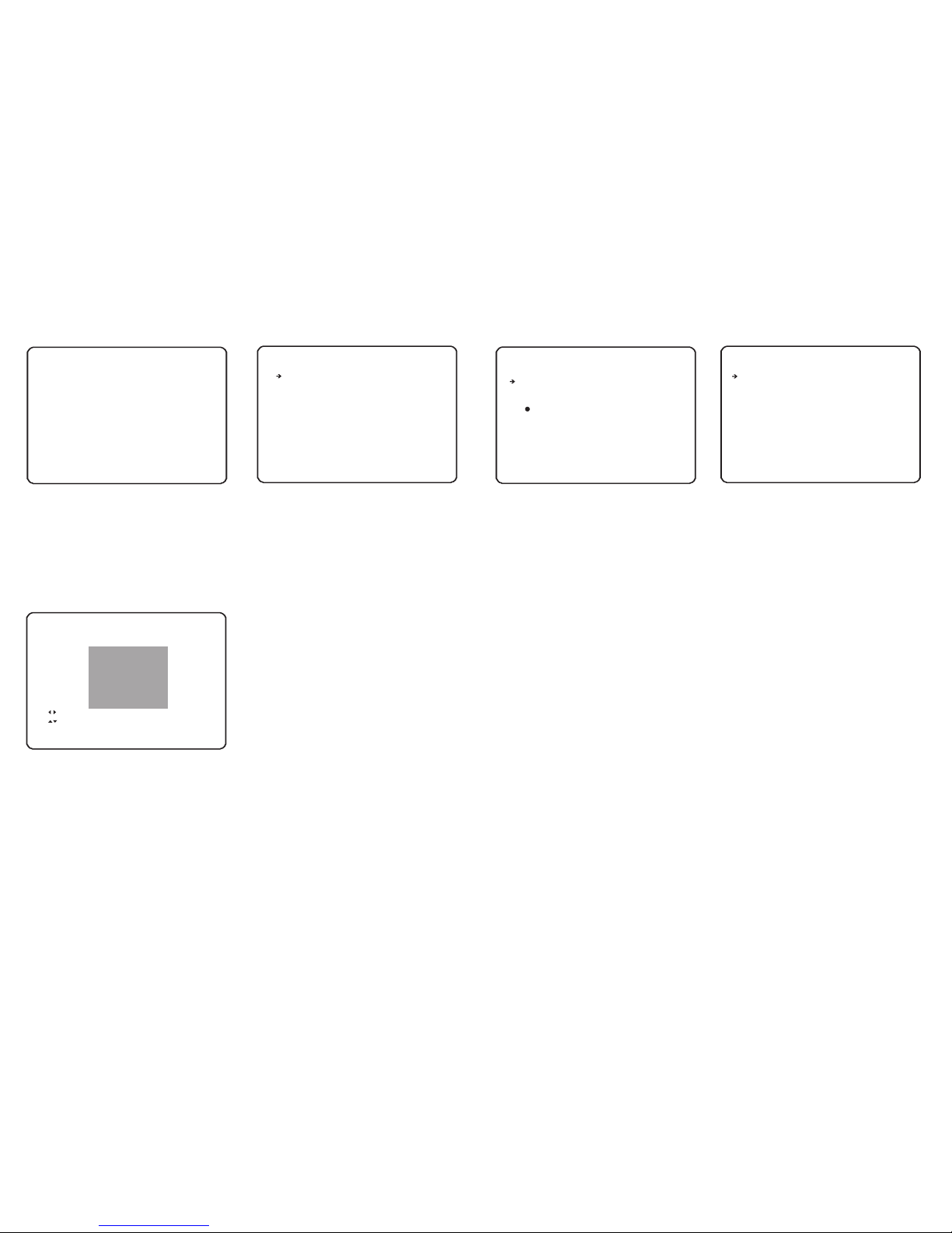
MOT ION SET UP
--- ----- ----- ----- ----- ----- -
PRE SET LOC K OFF
BAC K
EXI T
PWR U P ACT ION ON
AUT O FLIP OFF
JOG M AX SPEE D 240
JOG D IRECT ION INV ERSE
<PAR KIN G AC TIO N SET UP>
Motio n setup
PARK ING ACTI ON SETU P
-- - - - -- - - -- - - -- - - - -- - - -- - - -- -
PARK E NAB LE
WAIT T IME
PARK AC TION
ACTI ON NO ___
BA C K
EX I T
OFF
00: 10:00
pre set
From the motion setup menu, use the joystick
to highlight PARKING ACTION SETUP and
key: NEAR
PARK ENABLE - when set to ON, the speed
dome will run the specified park action after
the wait time has elapsed
WAIT TIME - can be set between one minute
and 4 hours. If no manual control occurs
during this time, the park action will run
PARK ACTION - choose the action to run after
the wait time has elapsed. This can be return
to home position, go to a preset or run a scan,
pattern or group.
Highlight the item to modify and key: NEAR
Use the joystick to change the setting and key:
NEAR to save or: FAR to cancel.
Parki ng action setu p
From the dome camera setup menu, use the
joystick to highlight MOTION SETUP and key:
NEAR
PRESET LOCK - when set to ON, preset
programming directly from the keyboard is
disabled to prevent tampering
PWR UP ACTION - you can set this with
LASTACT/PRESET/SCAN/PATTERN/
GROUP/OFF,the speed dome will resume the
setting operation when power is restored after
a power failure
AUTO FLIP (ON / OFF) - when set to ON, the
dome will flip 180 degrees when the tilt
position reaches 90 degrees.
JOG MAX SPEED - determines the maximum
speed in degrees / second the dome will move
during manual operation
JOG DIRECTION (INVERSE / NORMAL) when set to normal, the pan direction is
opposite to the joystick movement.when set
to inverse, the scan direction is the same with
the joystick movement.
<PARKING ACTION SETUP> - Configure
actions that run automatically after a defined
period of inactivity
Highlight the item to modify and key: NEAR
Use the joystick to change the setting and key:
NEAR to save or: FAR to cancel.
8
Edit ma sk
ED I T M A SK 1
-- - - - -- - - -- - - -- - - - -- - - -- - - -- -
MO V E T O T AR G E T PO S I TI O N
[N E A R :S E L EC T / FA R : C AN C E L]
ED I T M A SK 1
-- - - - -- - - -- - - -- - - - -- - - -- - - -- -
[ :A D J U ST M A S K WI D T H]
[ :A D J U ST M A S K HE I G HT ]
[N E A R :S A V E /F A R :C A N C EL ]
From the privacy zone menu, use the joystick
to highlight EDIT MASK and key: NEAR
Use the joystick to move the speed dome to
the approximate position and zoom level for
the privacy zone and key: NEAR to select or
FAR to cancel and return to the privacy zone
menu.
Move the joystick left and right to finely adjust
the width of the privacy zone and up and down
to finely adjust the height.
To save the privacy zone, key: NEAR or key:
FAR to cancel.
From the dome camera setup menu, use the
joystick to highlight CAMERA SETUP and key:
NEAR
FOCUS MODE
MANUAL - the operator must focus the
camera manually using the NEAR and FAR
keys.
SEMIAUTO -
the
camera automatically focuses during normal
PTZ movement but preset focus information is
stored when a preset is programmed and
recalled each time the preset is called.
AUTO - the module auto focuses continually
DIGITAL ZOOM (ON / OFF) - allows user to
set the digital zoom as ON or OFF.
FLICKERLESS (ON / OFF) - should be set to
ON when used in certain lighting conditions
(EG Fluorescent lighting) to prevent picture
flicker.
COLOUR (ON/OFF) - switches the module
between colour and b/w mode.
the camera automatically focuses,
but it could be switch to “Manual” mode by
pressing “Near” or “Far”, and it could be
switched back to “Auto” mode by move the
joystick up/down, right/left, or zoom in/out, and
the factory default is in “Semioauto” mode.
ZOO M CAMER A SE TUP
--- ----- ----- ----- ----- ----- -
FOC US MODE
DIG ITAL ZOOM
FLI CKERL ESS
COL OUR
STAB ILI ZE OFF
DET IAL 0
HR 7
<NE XT PAGE>
BAC K
EXI T
Zoom ca mera setup
SEM IAUTO
ON
OFF
ON
STAB IL IZE(o n/ off ) - th e st abi li ze f unc ti on
inter na lly det ec ts shak in g of the im ag e
due to ca me ra shak in g, and pe rf orms
digit al c ompen sa tion pr oc essin g to
suppr es s this sh ak ing and s ta biliz e th e
image o ut put.
Detai l - th is func ti on adju st s the
enhan ce ment of t he e dge of ob je cts
in the pi ct ure.
Page 11
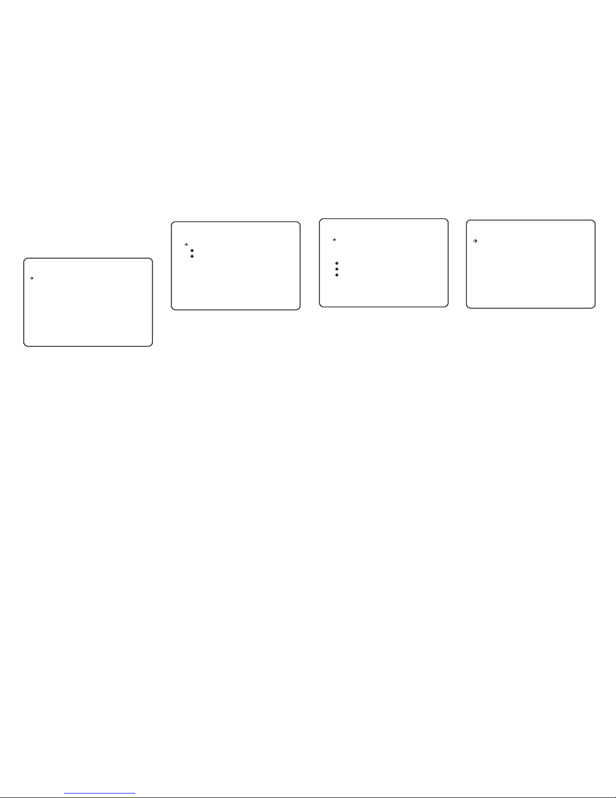
9
ZOO M CAMER A SE TUP
--- ----- ----- ----- ----- ----- -
<LA ST PAGE>
IMA GE FREE ZE
IMA GE FLIP
ZOO M SPEED 5
2D DN R OFF
3DD NR
<WH ITE BAL ANCE SE TUP>
<AU TO EXPO SUR E SETUP >
BAC K
EXI T
Zoom ca mera setup
ON
L/R
ON
From the zoom camera setup menu, use the
joystick to highlight WHITE BALANCE SETUP
and key: NEAR
WB MODE (AUTO / MANUAL/ATW)
AUTO - the speed dome determines the
optimum white balance settings for a given
scene
MANUAL - the operator can adjust white
balance settings manually
RED ADJUST - in manual mode, the red
colour content can be adjusted
BLUE ADJUST - in manual mode, the blue
colour content can be adjusted
Highlight the item to modify and key: NEAR
Use the joystick to change the setting and key:
NEAR to save or: FAR to cancel.
White b alance setup
WB S E T U P
-- - - - -- - - -- - - -- - - - -- - - -- - - -- -
WB M O D E
RE D A D J US T
BL U E A D JU S T
BA C K
EX I T
AU T O
-- -
-- -
From the zoom camera setup menu, use the
joystick to highlight AUTO EXPOSURE
SETUP and key: NEAR
WDR/BLC (ON/OFF) - switches WDR/BLC
compensation ON or OFF
DAY/NIGHT (AUTO/DAY/NIGHT) - the
operator can choose to fix the camera in to
DAY (colour) or NIGHT (B&W with IR cut filter
mode). In AUTO mode, the camera switches
between DAY and NIGHT depending on the
surrounding light level
AE MODE - in AUTO mode, the speed dome
determines optimum camera exposure
settings for a given scene. In modes other
than AUTO, the operator can adjust specific
exposure characteristics to suit a particular
scene.
BRIGHTNESS - allows users can set the
brightness of the video.
Highlight the item to modify and key: NEAR
Use the joystick to change the setting and key:
NEAR to save or: FAR to cancel.
Auto ex posure setup
AE SET UP
-- - - - -- - - -- - - -- - - - -- - - -- - - -- -
WDR /BLC
DAY/ NIG HT
SLO W SHUTT ER
AE MOD E
IRI S LEVEL
GAI N LEVEL
SHU TTER SP D
BRI GHTNE SS 7
BAC K
EXI T
OF F
AU T O
AU T O
-- -
-- -
-- —
IMAGE FREEZE(ON/OFF) - this function used
for run preset, when dome run between two
presets, the video will change directly from
one to another.
IMAGE FLIP(ON/OFF) - this function reverses
the video output from the camera upside/down
/left/right and etc.
ZOOM SPEED - this function can adjusts the
zoom speed level of the camera.
2D DNR - this function adaptive 2D filter
reducing noise in the brightness of the image,
it’s space-based.
3D DNR - this function adaptive 3D filter
reducing noise caused by movement,it’s time
based.
<WHITE BALANCE SETUP> - sub menu to
change the white balance settings
<AUTO EXPOSURE SETUP> - sub menu to
change the auto exposure settings
HR - this function called high resolution, it can
adjusts the video resolution tiny.
From the main menu, use the joystick to
highlight DOME CAMERA SETUP and key:
NEAR
<PRESET SETUP> - full management and
programming of individual presets.
<SCAN SETUP> - full management and
programming of scan functions.
<PATTERN SETUP> - full management and
programming of pattern tours.
<GROUP SETUP> - full management and
programming of group functions.
<ALARM SETUP> - full management and
programming of alarm functions.
<SCHEDULE SETUP> - full management and
programming of schedule functions.
Highlight the setup menu required and key:
NEAR
Remember: A menu item surrounded by
brackets shows it has a sub menu.
FUN CTION S ETUP
--- ----- ----- ----- ----- ----- -
<PR ESET SE TUP>
<SC AN SETU P>
<PATTE RN SETU P>
<GR OUP SET UP>
<AL ARM SET UP>
<SC HEDUL E SETUP >
Funct ion setup
BAC K
EXI T
Page 12
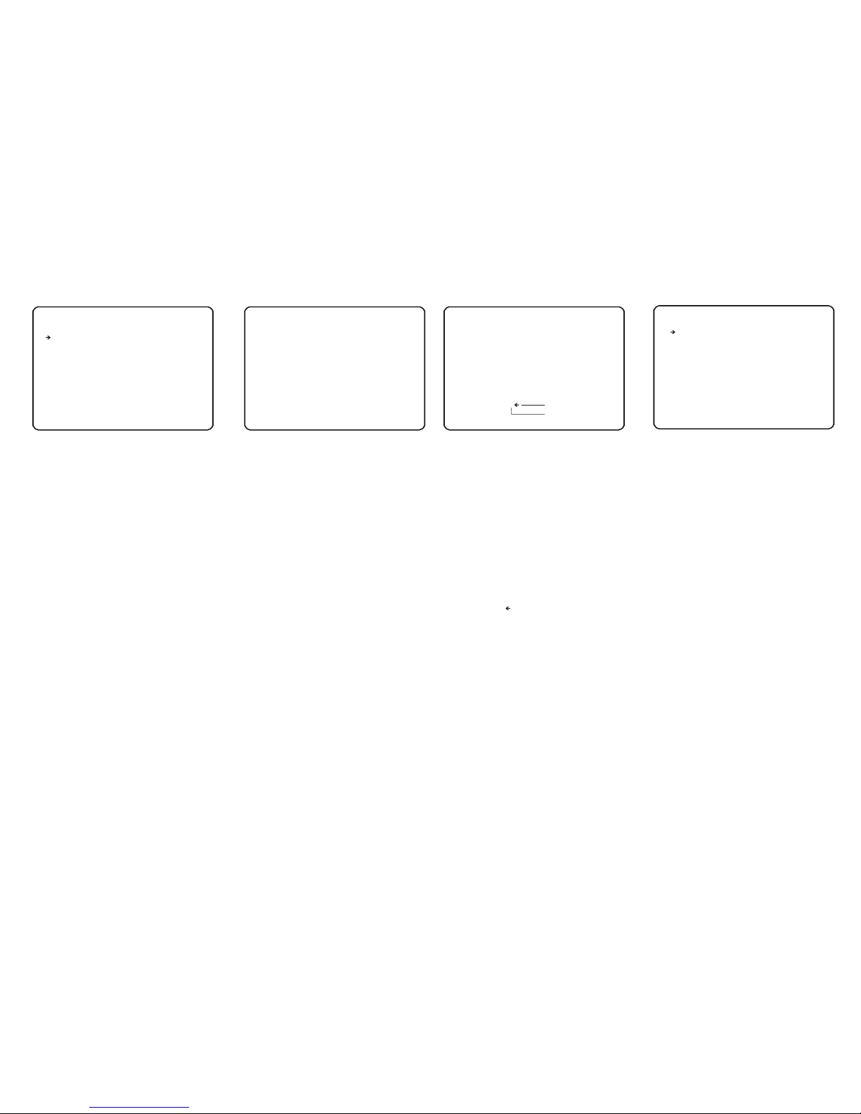
Edit la bel
ED I T L A BE L - P R ES E T 1
-- - - - -- - - -- - - -- - - - -- - - -- - - -- -
[ ]
-- - - - -- - - 12 3 4 5 67 8 9 0 OK
AB C D E FG H I J CA N C EL
KL M N O PQ R S T
UV W X Y Za b c d
ef g h i jk l m n
op q r s tu v w x
yz < > - /: .
Backs pa ce
Space
From the dome camera setup menu, use the
joystick to highlight PRESET SETUP and key:
NEAR
CLR PRESET - use this option to delete the
current preset position
<EDIT SCENE> - use this option to program
the preset position
<LABEL> - use to edit the preset label.
This option is only available when the
selected preset position is already
programmed
<CAMERA SET> - use to set the unique
camera parameters for the specific preset.
<RELAY OUT> - use to program the relay
outputs required (if any) when the preset is
called. This option is only available when
the selected preset position is already
programmed
Highlight the item to modify and key: NEAR
Use the joystick to change the setting and key:
From the preset setup menu, use the joystick
to highlight EDIT SCENE and key: NEAR
Using the joystick, move the speed dome to
the desired position and zoom level and key:
NEAR to save or: FAR to cancel.
PRE SET SET UP
-- - - - -- - - -- - - -- - - - -- - - -- - - -- -
PRE SET NO.
CLR P RESET
<ED IT SCEN E>
<LA BEL>
CAM ERA SET
REL AY OUT
BAC K
EXI T
1
CL E A R
GL O B A L
-- - -
Prese t setup
ED I T S C EN E - P R ES E T 1
-- - - - -- - - -- - - -- - - - -- - - -- - - -- -
MO V E T O T AR G E T PO S I TI O N
[N E A R :S A V E /F A R :C A N C EL ]
Edit sc ene
From the preset setup menu, use the joystick
to highlight EDIT LABEL and key: NEAR
The solid white square shows the current
cursor position.
The flashing white square shows the currently
selected character.
Move the joystick up / down / left / right to
choose the required character and key: NEAR
to insert it in the preset label. The solid white
square moves to the next cursor position.
Repeat until the preset label is complete.
If a mistake is made, use the joystick to select
the backspace ( ) and key: NEAR. The cursor
moves back one square.
Select OK to save the preset label or
CANCEL to lose changes, and key: NEAR to
exit
From the dome camera setup menu, use the
joystick to highlight Scan SETUP and key:
NEAR
Scan NO. (1-8) - shows the SCAN number
currently being modified.
CLEAR SCAN - deletes the currently selected
scan function.
<EDIT SCAN> - use this option to program the
scan function.
<LABEL> - use to edit the scan label.
This option is only available when the
selected scan is already programmed
RUN SCAN - runs the currently selected scan
function for testing purposes
SCAN SPEED - use this option to set the
speed in degrees / second the dome will move
during the scan run time.
JOG DIRECTION (INVERSE / NORMAL) when set to normal, the scan direction is
opposite to the joystick movement. when set
to inverse, the scan direction is the same with
the joystick movement.
Highlight the item to modify and key: NEAR
Use the joystick to change the setting and key:
NEAR to save or: FAR to cancel.
Scan se tup
SCA N SETUP
-- - - - -- - - -- - - -- - - - -- - - -- - - -- SCAN NO .
CLEAR S CA N CLEAR
<EDIT S CA N>
<LABE L>
RUN SCA N
SCAN SP EE D 60
JOG DIR EC TION IN VE RSE
BACK
EXIT
1
UND EFINE D
10
PRESET NO. (1 - 254) - The preset number
currently being modified
.
If the preset number is already defined, the
speed dome will move to that preset position,
otherwise UNDEFINED is displayed under the
preset number.
( note that preset 95
and 131~199 is reserved and cannot be used)
Page 13
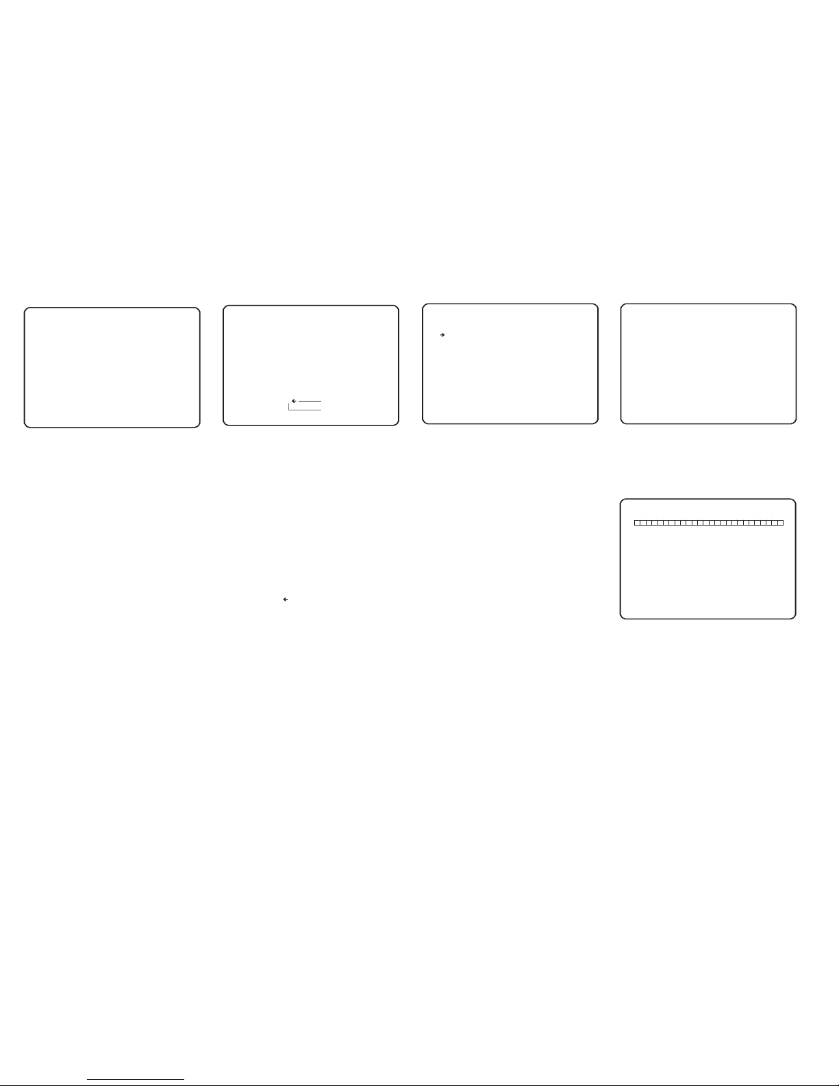
EDI T SCENE - S CAN
--- ----- ----- ----- ----- ----- ----- ----- ----- ----
MOV E TO START PO SITIO N
I+: SELEC T/I-: CANCE L
Edit la bel
ED I T L A BE L - P R ES E T 1
-- - - - -- - - -- - - -- - - - -- - - -- - - -- -
[ ]
-- - - - -- - - 12 3 4 5 67 8 9 0 OK
AB C D E FG H I J CA N C EL
KL M N O PQ R S T
UV W X Y Za b c d
ef g h i jk l m n
op q r s tu v w x
yz < > - /: .
Backs pa ce
Space
From the scan setup menu, use the joystick to
highlight EDIT LABEL and key: NEAR
The solid white square shows the current
cursor position.
The flashing white square shows the currently
selected character.
Move the joystick up / down / left / right to
choose the required character and key: NEAR
to insert it in the scan label. The solid white
square moves to the next cursor position.
Repeat until the scan label is complete.
If a mistake is made, use the joystick to select
the backspace ( ) and key: NEAR. The cursor
moves back one square.
Select OK to save the scan label or CANCEL
to lose changes, and key: NEAR to exit
BAC K
EXI T
Edit sc an
From the dome camera setup menu, use the
joystick to highlight EDIT SCAN and key:
NEAR
Move or spin the speed camera to any position
to be desired and key CLOSE to confirm start
position or key OPEN to cancel . and then
move or spin the speed camera to another any
position to be desired ,key CLOSE to confirm
or key OPEN to cancel end position.
PA T T E RN S E T UP
-- - - - -- - - -- - - -- - - - -- - - -- - - -- -
PA T T E RN N O .
CL E A R P AT T E RN
<E D I T P AT T E RN >
RU N P A T TE R N
BA C K
EX I T
1
CL E A R
From the dome camera setup menu, use the
joystick to highlight PATTERN SETUP and
key: NEAR
PATTERN NO. (1 - 4) - The pattern number
currently being modified.
CLEAR PATTERN - the currently selected
pattern can be deleted.
<EDIT PATTERN> - allows the operator to
program a patten tour.
RUN PATTERN - runs the currently selected
pattern for testing purposes.
Highlight the item to modify and key: NEAR
Use the joystick to change the setting and key:
NEAR to save or: FAR to cancel.
Patte rn setup
ED I T P A TT E R N 4
-- - - - -- - - -- - - -- - - - -- - - -- - - -- -
MO V E T O S TA R T P OS I T IO N
[I + : S TA R T / I- : C AN C E L
ED I T P A TT E R N 4
[I + : S AV E / I -: D E LE T E ]
From the pattern setup menu, use the joystick
to highlight EDIT PATTERN and key: NEAR
Position the speed dome to the desired
starting point and key: CLOSE
Move the dome to the various positions and
zoom levels required for the pattern. The white
squares at the top of the display show
remaining storage and disappear as the
pattern is recorded.
To save the pattern, key: CLOSE
To abandon pattern programming, key: OPEN
Note: Pattern tour memory is only used when
movements are recorded. Pauses between
movements, regardless of time, do not use
pattern tour memory
Edit pa ttern
11
Page 14
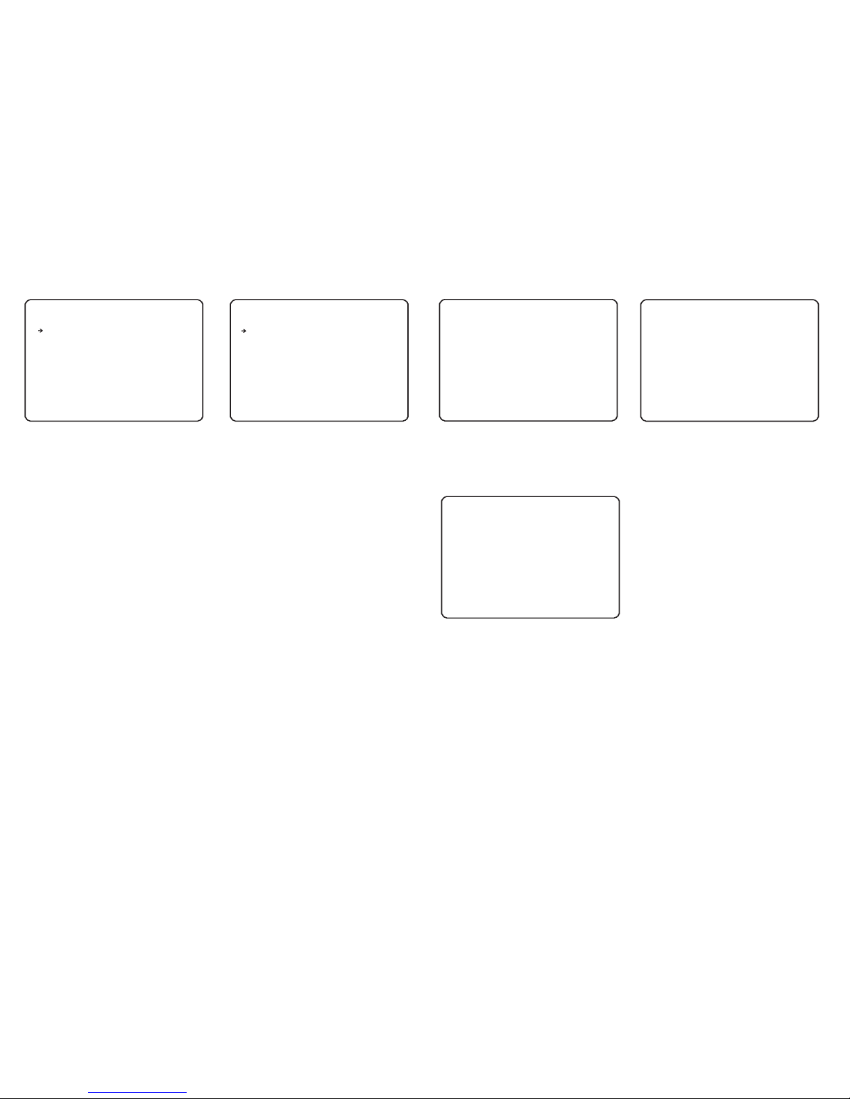
From the dome camera setup menu, use the
joystick to highlight GROUP SETUP and key:
NEAR
GROUP NO. (1-8) - shows the group number
currently being modified.
CLEAR GROUP - the currently selected group
can be deleted.
<EDIT GROUP> - allows the operator to
program the group functions.
RUN GROUP - runs the currently selected
group for testing purposes
Highlight the item to modify and key: NEAR
Use the joystick to change the setting and key:
NEAR to save or: FAR to cancel.
From the group setup menu, use the joystick
to highlight EDIT GROUP and key: NEAR
To edit the group, key: NEAR again
Header explanation:
NO - the item number (between 1 & 20)
ACTION - the specific action for this item
NO.- the action number (eg if ACTION is set to
PRESET, this value can be between 1 & 255
DWELL - the amount of time before the next
action in the list is called
OPT - for PRESET actions, this value is the
speed at which the dome moves to the preset.
For SCAN and PATTERN, this value is the
number of times the action is repeated before
the next action is called
Move the joystick up and down to choose the
group item to modify and key: NEAR. The
ACTION is highlighted in white
Move the joystick up and down to change the
action type between NONE, PRESET, SWING
and PATTERN.
Move the joystick left and right to select and
edit values for NO.,DWELL & OPT.
Group s etup
Edit gr oup
GRO UP SETU P
--- ----- ----- ----- ----- ----- GRO UP NO.
CLE AR GROU P
<ED IT GROU P>
RUN G ROUP
BA C K
EX I T
EDI T GROUP 1
--- ----- ----- ----- ----- ----- NO ACT ION NO. D WELL OP T
--- ----- ----- ----- ----- ----- 1 NON E
2 NON E
3 NON E
4 NON E
5 NON E
--- ----- ----- ----- ----- ----- BAC K
CAN CEL [NE AR: EDIT]
1
UND EFINE D
CLE AR
12
Key NEAR to save this item and continue
adding more items as necessary, or key FAR
to exit.
Edit gr oup
ED I T G R OU P 1
-- - - - -- - - -- - - -- - - - -- - - -- - - -- NO A C T I ON # # # D WE L L O PT
-- - - - -- - - -- - - -- - - - -- - - -- - - -- 1 PA T T E RN
2 PR E S E T
3 SW I N G
4 PR E S E T
5 PR E S E T
-- - - - -- - - -- - - -- - - - -- - - -- - - -- BA C K
CA N C E L [N E A R: E D IT ]
1
5
3
10
4
1
36 0
8
11 0
55
00 : 0 3
00 : 0 8
00 : 0 3
00 : 1 5
01 : 3 0
ALA RM SE TUP
-- - - - -- - - -- - - -- - - - -- - - -- - - -- -
BA C K
EX I T
From the function setup menu, use the joystick
to highlight ALARM SETUP and key: NEAR
<ALARM INPUT SETUP> - allows the
operator to program the alarm input function.
<ALARM RELAY SETUP> - allows the
operator to program the alarm relay function.
Highlight the item to modify and key: NEAR
Use the joystick to change the setting and key:
NEAR to save or: FAR to cancel.
Alarm s etup
<AL ARM INP UT SETU P>
<AL ARM REL AY SET UP>
-- - - - -- - - -- - - -- - - - -- - - -- - - -- -
BAC K
EXI T
ALA RM IN PUT S ETUP
ALA RM I/ O 1
ALA RM EN ABL E OFF
ALA RM TY PE -- -- ALA RM ACT ION NON E
ACTI ON NO --- --- REL AY OUT - ----- REL AY RETA IN 3SEC
Alarm i nput setup
From the alarm setup menu, use the joystick
to highlight ALARM INPUT SETUP and key:
NEAR
ALARM I/O - shows the alarm I/O number.
ALARM ENABLE - allows the operator to set
the enable/disable of the alarm I/O.
ALARM TYPE - allows the operator to set the
alarm type of the alarm I/O.
ALARM ACTION - allows the operator to set
the alarm action and the action number for the
alarm I/O.
RELAY OUT - allows the operator to set the
relay out option for the alarm I/O.
RELAY RETAIN - allows the operator to set
the relay retain time for the alarm I/O.
Page 15
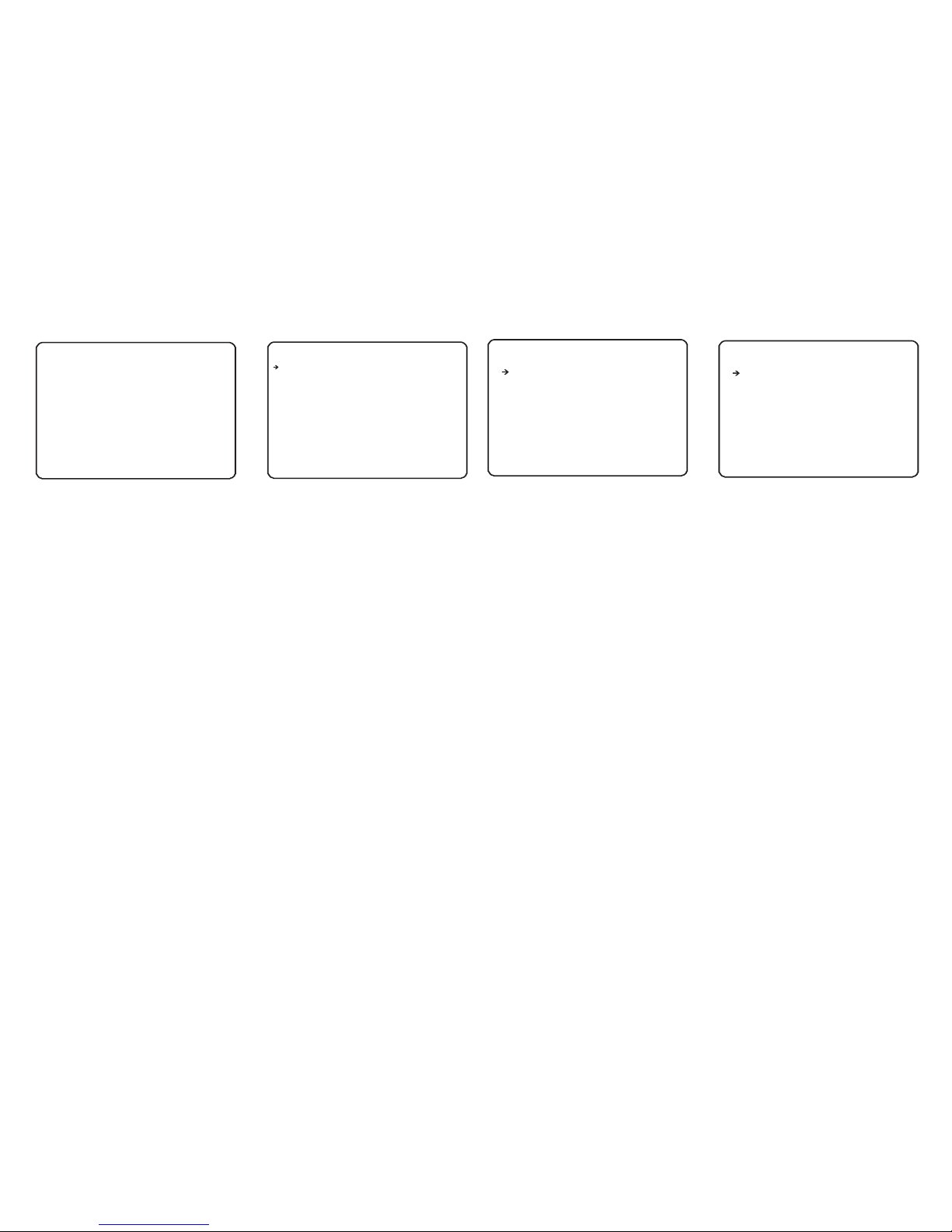
From the alarm setup menu, use the joystick
to highlight ALARM RELAY SETUP and key:
NEAR
RELAY 1....4(N.O/N.C) - allows the operator
to set the alarm relay type as N.O or N.C.
Highlight the item to modify and key: NEAR
Use the joystick to change the setting and key:
NEAR to save or: FAR to cancel.
-- - - - -- - - -- - - -- - - - -- - - -- - - -- -
BAC K
EXI T
REL AY SET UP
REL AY1 N .O
REA LY2 N .O
REL AY3 N .O
REL AY4 N .O
Relay s etup
SCH EDULE N O 1
-- - - - -- - - -- - - -- - - - -- - - -- - - -- -
SCH EDULE N O. 1
SCH EDULE E NABLE O FF
ACTI ON NONE
ACTI ON NO --- ---- REL AY OUT - ----- - MON TH/WE EK MONT H
STAR T TIM E JAN:0 1:00: 00
END T IME JAN :01:0 0:00
BAC K
EXI T
Sched ule setup
From the function setup menu, use the joystick
to highlight SCHEDULE SETUP and key:
NEAR
SCHEDULE NO. - shows the schedule
number.
SCHEDULE ENABLE - allows the operator to
set the enable/disable of the schedule.
ACTION - allows the operator to set the action
and the action number for the schedule.
RELAY OUT - allows the operator to set the
relay out option for the schedule.
MONTH/WEEK - allows the operator to set the
month/week/day of the schedule.
START TIME - allows the operator to set the
start time for the schedule, the time format
depends on the parameter of MONTH/WEEK
/DAY. the time can precise to minute.
END TIME - allows the operator to set the end
time for the schedule, the time format depends
on the parameter of MONTH/WEEK/DAY.the
time can precise to minute.
Highlight the item to modify and key: NEAR
Use the joystick to change the setting and key:
NEAR to save or: FAR to cancel.
13
SYS TEM SET UP
--- ----- ----- ----- ----- ----- -
LAN GUAGE E NGLIS H
<DAT E/T IME SET UP>
<PAS SWO RD>
<FAN /HEATE R SET UP>
<SY STEM IN ITIAL IZE>
Syste m setup
BAC K
EXI T
From the main menu, use the joystick to
highlight SYSTEM SETUP and key: NEAR
LANGUAGE - you can select different
language. the system provide 8 kind language.
<DATE/TIME SETUP> - allows user to set the
date/time.
<PASSWORD> - allows user to set the
password of the dome, then nobody can
modified the dome information without the
password.
<FAN/HEATER SETUP> - allows user to set
the fan/heater working information.
<SYSTEM INITIALIZE> - allows user to set
the different part of dome back to factory
setting.
Highlight the item to modify and key: NEAR
Use the joystick to change the setting to ON
and key: NEAR to run or: FAR to cancel.
DATE /TI ME SETU P
--- ----- ----- ----- ----- ----- -
DATE 0 3/F EB/20 13(FR I)
TIM E 02:10 :36(H /M/S)
Date/ Time set up
BAC K
EXI T
From the system setup menu, use the joystick
to highlight DATE/TIME SETUP and key:
NEAR
Move the highlight to DATE , you can setup
current year, mouth, day. After completed
adjusting ,key NEAR to confirm or key FAR to
cancel. and the TIME setup is just like the
DATE.
Page 16
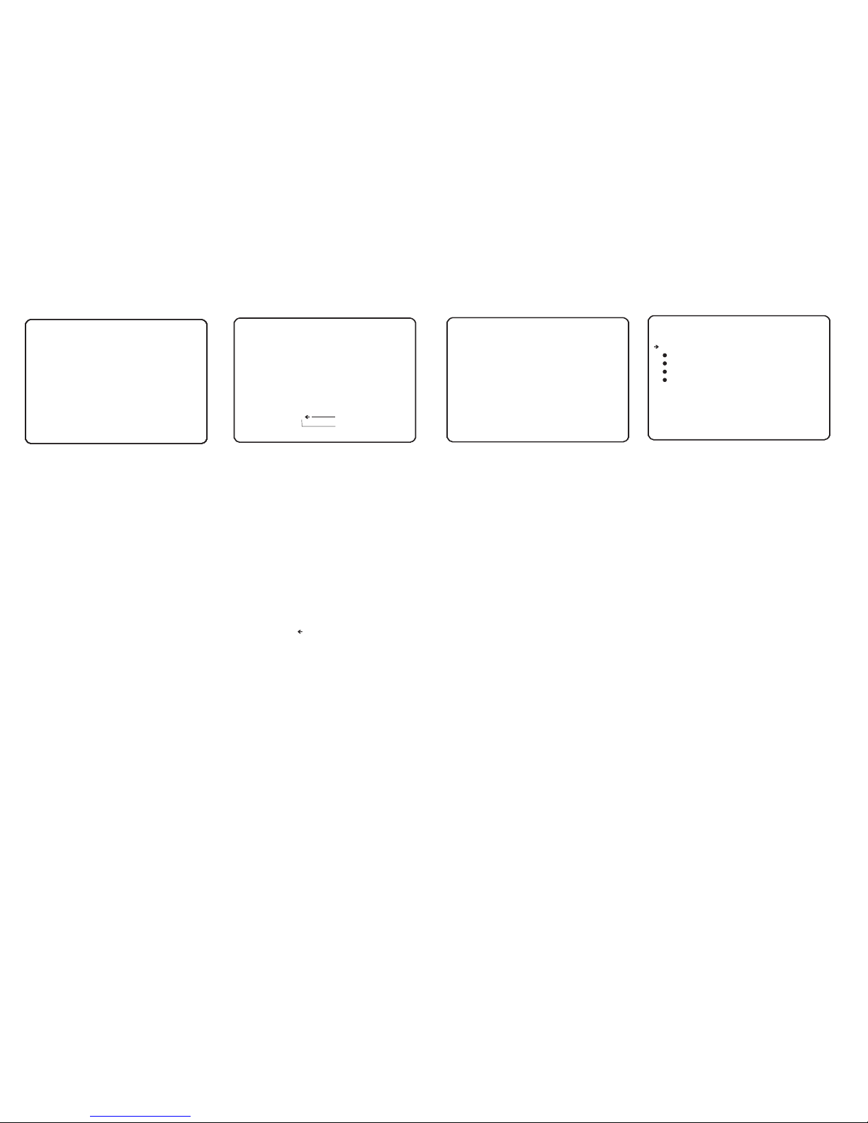
From the system setup menu, use the joystick
to highlight PASSWORD SETUP and key:
NEAR
CHECK PASSWORD (ON/OFF) - when set to
ON, the correct password must be entered to
access the speed dome setup menus
<EDIT PASSWORD> - allows the current
password to be changed
Edit pa ssword
PASS WOR D SETUP
--- ----- ----- ----- ----- ----- CHE CK PASSW ORD O FF
<PAS S WOR D EDIT>
BAC K
EXI T
14
Passw ord edit
From the password setup menu, use the
joystick to highlight EDIT PASSWORD and
key: NEAR
The solid white square shows the current
cursor position.
This flashing white square shows the currently
selected character.
Move the joystick up / down / left / right to
choose the required character and key: NEAR
to insert it in the password. The solid white
square moves to the next cursor position.
Repeat until password entry is complete.
If a mistake is made, use the joystick to select
the backspace ( ) and key: NEAR. The cursor
moves back one square.
Select OK to save the password or CANCEL
to lose changes and key: NEAR to exit
Remember: When CHECK PASSWORD is set
to ON, each time the operator attempts to
enter the speed dome setup menu, the above
screen will be displayed. The correct
password must be entered to continue with
menu setup
PA S S W OR D E D IT
-- - - - -- - - -- - - -- - - - -- - - -- - - -- -
[ ]
-- - - - -- - - 12 3 4 5 67 8 9 0 OK
AB C D E FG H I J CA N C EL
KL M N O PQ R S T
UV W X Y Za b c d
ef g h i jk l m n
op q r s tu v w x
yz < > - /: .
Backs pa ce
Space
FAN/ HEATER /SETU P
--- ----- ----- ----- ----- ----- -
HEAT O N TEM P 5 C
FAN RU N TEMP 45 C
DEF OG ACTIO N OFF
BAC K
EXI T
Fan/H eater setup
From the system setup menu, use the joystick
to highlight SYSTEM INITIALIZE and key:
NEAR
CLEAR ALL DATA - selecting this option will
perform a full factory reset on the speed
dome. All presets, swing functions, patterns,
groups and privacy zones will be erased
CLR DISPLAY SET - this option will reset the
on screen display settings to factory default
and erase all privacy zones
CLR CAMERA SET - this option will reset the
camera module settings to factory default
CLR MOTION SET - this option will reset the
motion menu settings to factory default
CLR FUNCTION SET - this option will erase
all presets, scans, patterns and groups date.
REBOOT CAMERA - this option will reboot
the camera zoom module.
REBOOT SYSTEM - this option will reboot the
speed dome.
Highlight the item to modify and key: NEAR
Use the joystick to change the setting to YES
and key: NEAR to run or: FAR to cancel.
Syste m initialize
SYS TEM INI TIALI ZE
--- ----- ----- ----- ----- ----- -
CLE AR ALL DATA NO
CLR D ISPLAY SE T NO
CLR C AMERA SE T NO
CLR M OTION S ET NO
CLR F UNCTI ON SET NO
REB OOT CAM ERA NO
REB OOT SYS TEM NO
BAC K
EXI T
From the system setup menu, use the joystick
to highlight FAN/HEATER SETUP and key:
NEAR
HEAT ON TEMP - allows users to set the
lowest heater working temp.
FAN RUN TEMP - allows users to set the
lowest fan working temp.
DEFOG ACTION - allows users to set the
ON/OFF of the defog function.
Highlight the item to modify and key: NEAR
Use the joystick to change the setting and
key: NEAR to store or: FAR to cancel.
Page 17
KEY BOARD O PERATI ON
KEY:
NEA R SAVE/E NTE R
FAR DI SCARD /QUIT
JOY STICK :
RIG HT - ENTE R
LEF T - DISCA RD/QU IT
UP/ DOWN - CU RSOR/ MODIF Y
BAC K
EXI T
Help
From the main menu, use the joystick to
highlight HELP and key: NEAR
NEAR - this ‘near’ means the key working as
‘near’ function, in our keyboard, it calls
‘NEAR’, so we defined this function as ‘NEAR’,
press this key, it will work as SAVE or ENTER
in our OSD menu.
FAR - this ‘far’ means the key working as ‘far’
function, in our keyboard, it calls ‘FAR’,so we
defined this function as ‘FAR’,press this key, it
will work as DISCARD or QUIT.
RIGHT - in OSD menu, when you move the
joystick right, it will work as ENTER or SAVE
function. it just like the key NEAR.
LEFT - in OSD menu, when you move the
joystick left, it will work as DISCARD or QUIT
function, it just like the key FAR.
UP/DOWN - in OSD menu, when you move
the joystick up/down, it will move the cursor
up/down or modify the parameters.
you can see the help information about
keyboard operation and joystick.
15
Page 18
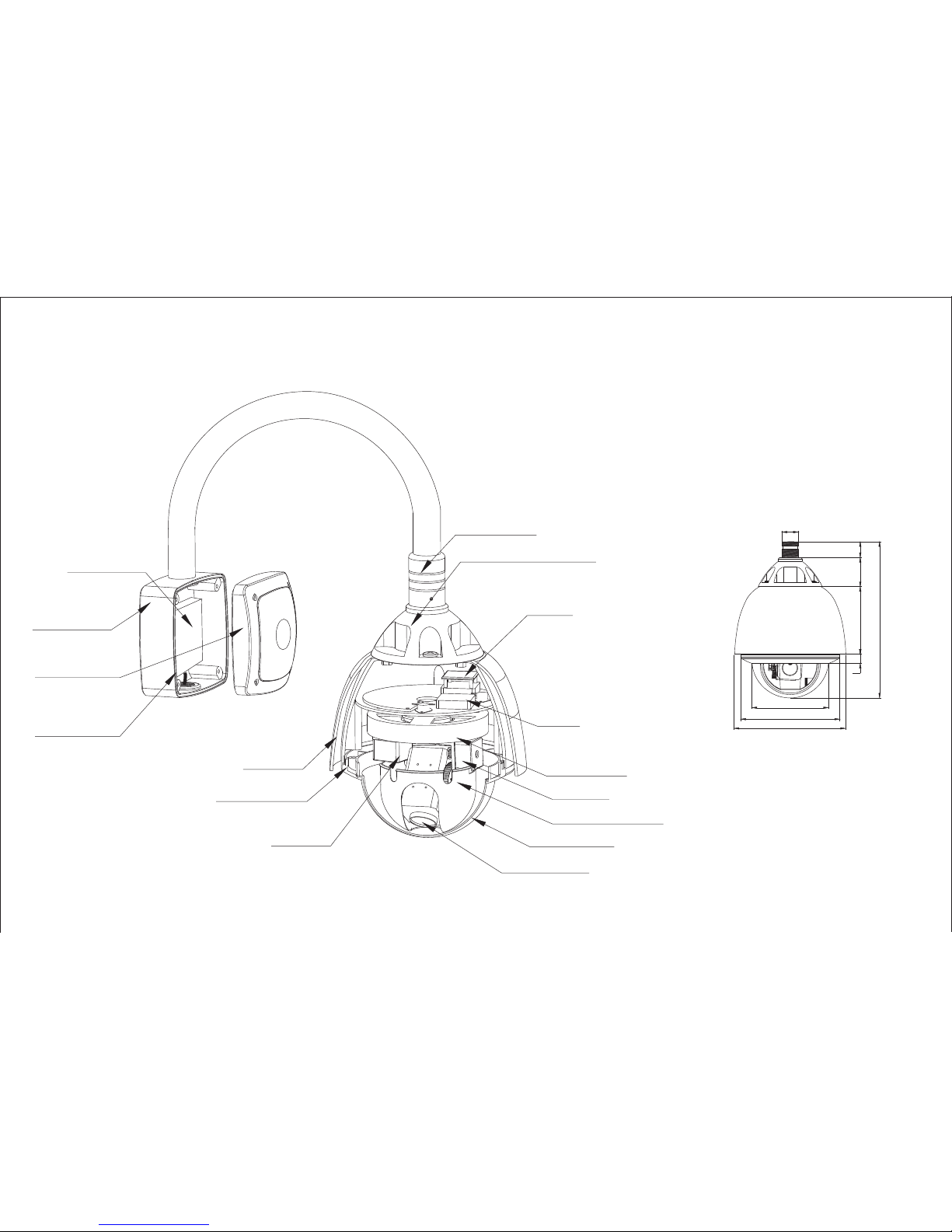
Heater
Fan
Shield Mount
Tilt Motor
Inner dome cover
Zoom Module
Dome Cover
Pan Motor
Sunshield
Dome Housing
Bracket Mount
Base
Bracket Upper
Cover
Seal
Housing Upper Cover
Bracket Joint
PCB
Parts and dimensions
230
33
3353140
19
156
325
201
16
Appendix Of Outdoor High Speed Dome System
Page 19
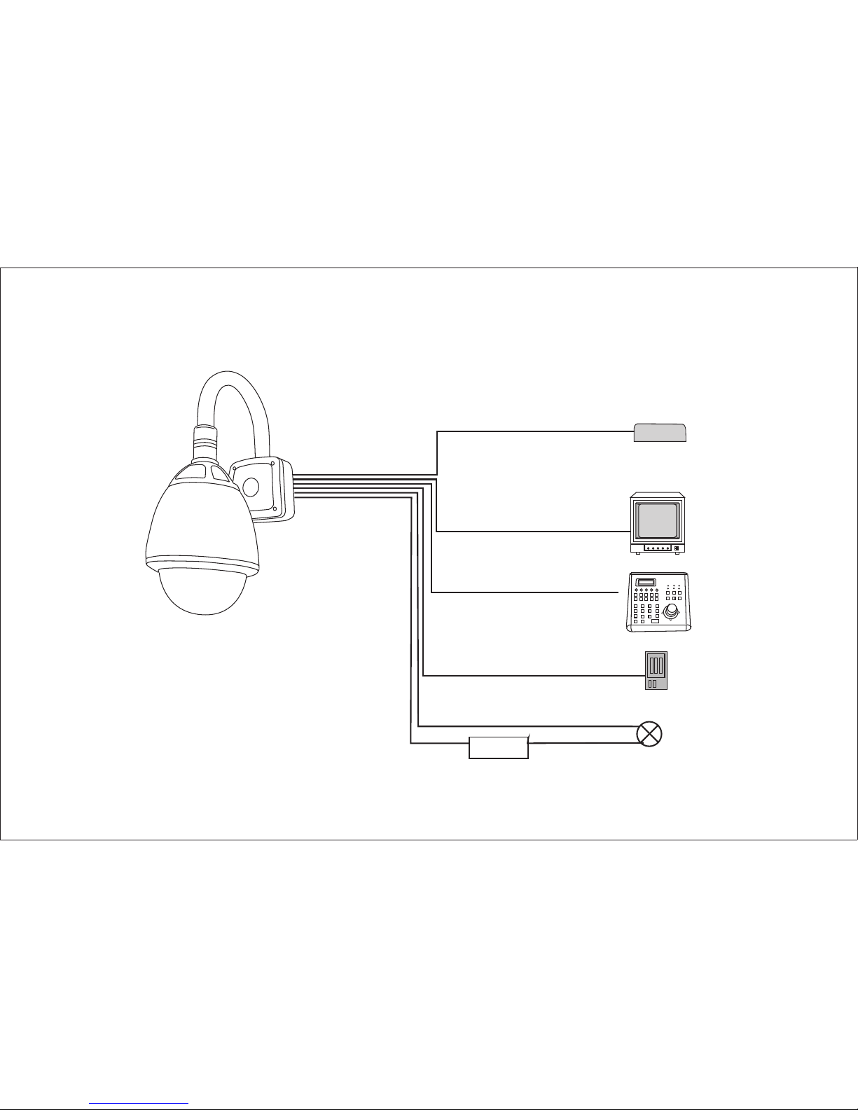
12V DC ~ 2 4V AC PSU
485
Cabl e
RS-
Video Ca bl e
Alarm Input
Cable
Powe r Cable
Alar m Sensor
Sire n / Light etc .
Sire n / Light etc .
powe r source
Alarm Output
Cable
Wiring schematic
17
Page 20
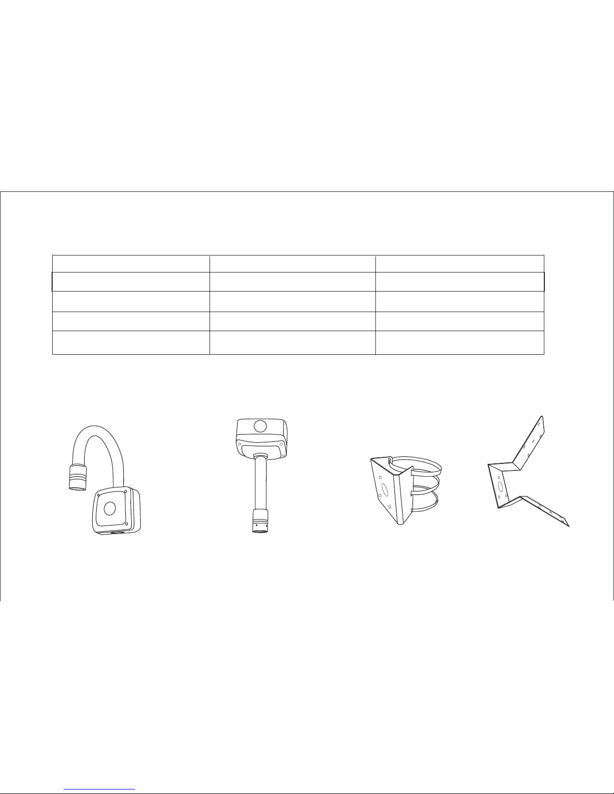
Fan & Heater
Current(A)
Voltage
Power Consuption
Trigger Temperature
Fan
Heater
0.1A
0.17A/2A
12V/24V
12V
1.2W
12W/48W
More than40℃
Less than35℃
Brackets for option
Wall bracket
Pendent Bracket
Corner Bracket
Pole Bracket
18
(V)
Page 21
19
1/ 4" SONY EXVIEW HAD CCD
DC12 v/2.2A, AC 24V/2.8 A
f=3.9 mm (W) to 8 5. 8mm(T )
22X( So ny e ff io -s zoom mou dl e)
Sensor D ev ic e
Horizo nt al R es .
650TVL (7 00 TV L B/W)
22X Opti ca l Zo om
Zoom
12X Digi ta l Zo om
Angle of View
48(wid e en d) t o 2. 8( te le end)
Focal Le ng th
F=1.6 - 3. 7
Color: 0 .5 Lu x
B/W: 0.01lux
Auto/D ay /N ig ht
More tha n 50 dB
Auto/M an ua l
Yes
Min.Il lu mi na ti om
Day & Nigh t
S/N Rati on
Focal
Iris
WDR
White Ba la nc e
Backli gh t
Range
Pan/Til t Sp eed
Preset
Patter n
Scan
Group
Commun ic at io n
Protoc ol
Alarm I/ O
Fan/He at er
Rate Pow er
Dimens io n
Net weig ht
Operat io n Temp
Auto/M an ua l/ In do or/outdoor/ATW
On/Off
Up to 254 pr es et s( wi th e ditable labels)
4 patter ns
8 Scans
8 Groups (2 0 ac ti on e nt ities per Groups)
RS - 485 (Ma x. 2 55 u ni t)
Pelco- D/ Pe lc o- P sa ms un g au to r econgnize
8 input /o ut pu t( op ti cal)
Build in
Dome: 15 2M M, H ou si ng : 2 14X260(H)mm
Auto/M an ua l
Pan 360 (e nd le ss )/ Tilit 90
Max. Pre se t Sp ee d: 3 60 / Sec.
Max: Pre se t Sp ee d: 4 00 / Sec.
Manual : 0. 05 - 3 60 / Se c. (proportional t o zo om )
-40 C - 60 C
Scan: 10 - 3 60 / Se c.
Page 22
2020
Sensor Device 1/3”Sony Exview HAD CCD 1/4" Sony CCD 1/4" Sony CCD
Horizontal Res. 650 TVL Color (700 TVL B/W)
Zoom 18x Optical Zoom 12x Digital Zoom 28x Optical Zoom 32x Digital Zoom 36x Optical Zoom 32x Digital Zoom
Angle of View 57.8 (W) 1.7 (T) 57.8 (W) 1.7 (T) 57.8 (W) 1.7 (T)
Focal Length
f=3.4(Wide) – 61.2(Tele)mm f=3.4(Wide) - 95.2(Tele)mm f=3.4(Wide) - 122.4(Tele)mm
F=1.6-4.5 F=1.6-4.5 F=1.6-4.5
Min.illumination Color : 0.2 lux , B/W : 0.02 lux Color : 0.5 lux , B/W : 0.2 lux Color DSS : 0.001 lux , B/W DSS : 0.0004 lux
Day & night Auto/Day/Night Auto/Day/Night Auto/Day/Night
S/N Ratio More than 50dB More than 50dB More than 50dB
Focus
Auto/Manual
Iris
Auto/Manual
WDR
No Yes Yes
White Balance
Auo/Manual/Indoor/outdoor
Backlight
On/Off
Range Pan 360°(Endless)/Tilt 90°
Pan/Tilt Speed Max.Preset Speed:360°/sec.
Manual:0.05°-360
Specifications
Zoom Camera 18X(Sony Effio-S Module) 28X(Sony Effio-P Module) 36X(Sony Effio-P Module)
°/sec(proportional to zoom)
Max: Preset Speed: 400°/sec.
Scan:10°-360°/sec.
Preset
254 Preset(with editalbe labels)
Pattern
4 Pattern (1 min/Pattern)
Swing
8 Scan
Group
8 Group(20 action entities per Group)
Communication RS-485 (Max.255 unit)
Protocol
Pelco-D.Pelco-P Samsung auto recongnize
Alarm I/O
8 input/ 4 output (optional)
Fan/Heater Built in
Rated Power
DC12V/2.5A,AC 24V/2.5A
Dimension
Dome:152mm, Housing:214x260(H)mm
Net Weight Approx 2.5KG
Operating Temp -40°C - 60°C
? ¡« ? ? ¡« ? ? ¡« ?
Scan
57.8 C (W )-1.7 C(T ) 57.8 C (W )-1.7 C(T ) 57.8 C (W )-1.7 C(T )
Approx 5KG
DC12V/2.2A,AC 24V/2.8A
Page 23
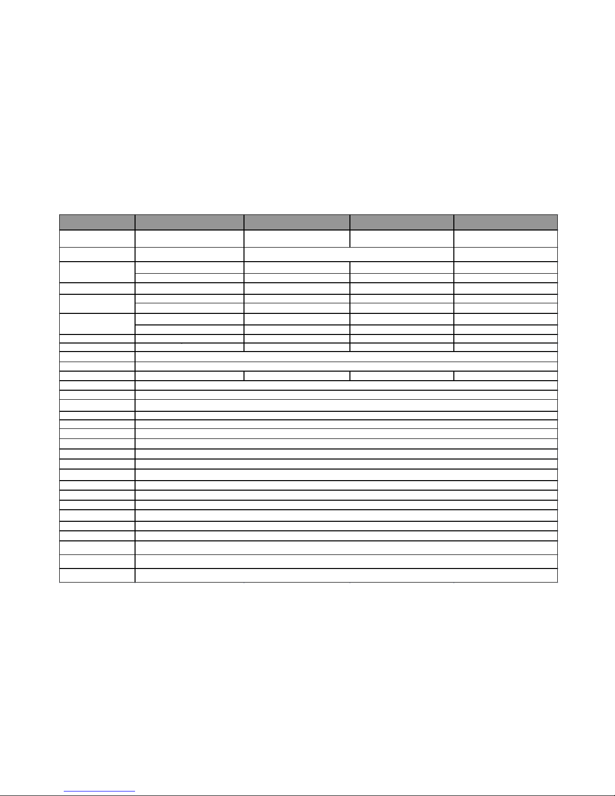
Model No. 27x (Samsung Module) 30x (Samsung Module) 33x (Samsung Module) 37x (Samsung Module)
Sensor Device
Horizontal Res.
27x Optical Zoom 30x Optical Zoom 33x Optical Zoom 37x Optical Zoom
16x Digital Zoom 2-16x Digital Zoom 16x Digital Zoom 16x Digital Zoom
Angle of View 55.5°(Wide) to 1.59°(Tele) 55.5°(Wide) to 1.96°(Tele) 55.5°(Wild) to 1.77°(Tele) 55.5°(Wide) to 1.59°(Tele)
f=3.5 to 94.5mm f=3.5 to 105.0mm f=3.5 to 115.5mm f=3.5 to 129.5mm
F=1.6-2.9
F=1.6-3.2
F=1.6-3.6 F=1.7-3.9
Color:0.2 Lux/F1.6 (50 IRE) Color:0.2 Lux/F1.6 (50 IRE) Color:0.7Lux/F1.6 (50 IRE) Color:1Lux/F1.6 (50 IRE)
B/W:0.02 Lux/F1.6 (50 IRE) B/W:0.2 Lux/F1.6 (50 IRE) B/W:0.03 Lux/F1.6 (50 IRE)B/W:0.1Lux/F1.6 (50 IRE)
Day & night Auto/Day/Night ICR ICR ICR
S/N Ratio More than 50dB
More than 50dB More than 50dB More than 50dB
Focus
Iris
WDR No No Y es Yes
White Balance
Backlight
Range
Pan/Tilt Speed
Preset
Pattern
Swing
Group
Communication
Protocol
Alarm I/O
Fan/Heater
Rated Power
Dimension
Net Weight
Operating Temp
Specifications
Auto/Manual
Auto/Manual
Auo/Manual/Indoor/outdoor/ATW
On/Off
Pan 360°(Endless)/Tilt 90°
1/4 inch, Interline Transfer CCD 1/4 inch, Double Density Interline Transfer CCD
Color:560 TVL; B/W:680 TVL
Pelco-D.Pelco-P Samsung auto recongnize
8 input/ 4 output (optional)
Built in
Max.Preset Speed:360°/sec.
Manual:0.05°-360°/sec(proportional to zoom)
Max: Preset Speed: 400°/sec.
Scan:10°-360°/sec.
254 Preset(with editalbe labels)
4 Pattern (1 min/Pattern)
DC12V/2.2A,AC 24V/2.8A
Dome:152mm, Housing:214x260(H)mm
Approx 5KG
-40°C - 60°C
Zoom
Focal Length
Min.illumination
8 Scan
8 Group(20 action entities per Group)
RS-485 (Max.255 unit)
1/4" Sony 960H Exview HAD CCD II
1/4" Interline Transfer CCD
1/4" Double Density
Interline Transfer CCD
1/4" Sony 960H Exview HAD CCD II
Color:650TVL;B/W:700TVL
Color:650TVL;B/W:700TVL
6
1
0.2
0.01
2
2
Scan
21
 Loading...