

Polydome PD-1250, PD-1230, PD-1240 Assembly Instructions Manual
Assembly Instructions
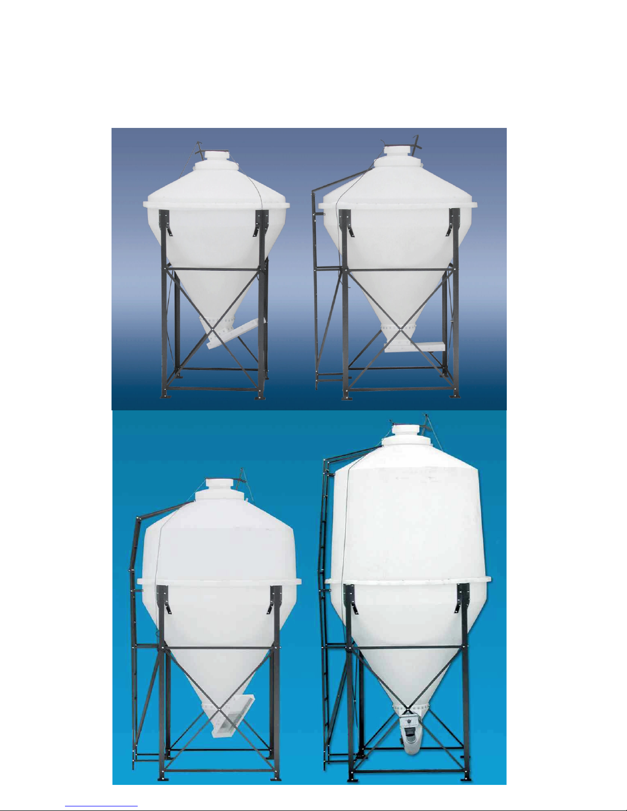
.9, 1.5, 2.5 & 3.5 Ton Bulk Bin
.9 Ton
1.5 Ton
2.5 Ton
3.5 Ton
Assembling .9, 1.5, 2.5 & 3.5 Ton Bulk Bin
The .9 Ton uses 4 – Leg 2 1/2” angles 92”
long 8 – Leg Spacers 1 1/4” angles 43 1/2” long 8-
X Bracing 1” flat straps 66” long 4 – Leg Pads 5 X
5 Plate w/tab & 20 – 5/16 x 1” hex bolts and nuts.
The 1.5, 2.5, & 3.5 use 4 - Legs 2 1/2” an-
gle 92” Long, 8 – Leg Spacers 1 1/4” angles 51”
long , 8-X Bracing 1” flat straps 75 1/2” long , 4 –
Leg Pads 5 X 5 Plates w/tab & 20- 5/16 X 1” hex
bolts and nuts.
Step 1:
Bolt the Leg Pads to the bottom of the legs
using the 3/8 X 1” Hex bolts.
Now take 2- Legs and 2– Leg Spacers and
2– X Brace Straps and make a section like diagram
1, put the angles to the inside of the leg with the
angle up, on the top one and angle down on the bottom one. Put the flat strap on the out side of the leg
angle & use 5 - 5/16 X 1” hex bolts to fasten in
place, (finger tighten only). Assemble 2 sections
like this. Now with help stand the two sections up
spaced accordingly facing each other, now add the
leg spacers and X bracing between them just like
Step 1 to form a square. Now tighten all
bolts.
Diagram 1
Cone to Frame .9, 1.5, 2.5 & 3.5 Diagram-2
Step 2:
With the frame assembled drop the cone
into the frame from the top. There are tabs welded
to the legs to bolt the cone into place with. Drill a
5/16” hole through the top hole in each tab and bolt
securely using the 5/16 X 1” carriage bolts, (bolt
from the inside out). Now drill the remaining holes
and bolt securely using the 5/16 X 1” carriage bolts.
These tabs are long enough to reach past the sides
of the cone and down the slope, you will need to
bend this part into the cone and drill and bolt into
place using the 5/16 X 1” Carriage bolts again from
the inside out. Diagram 2
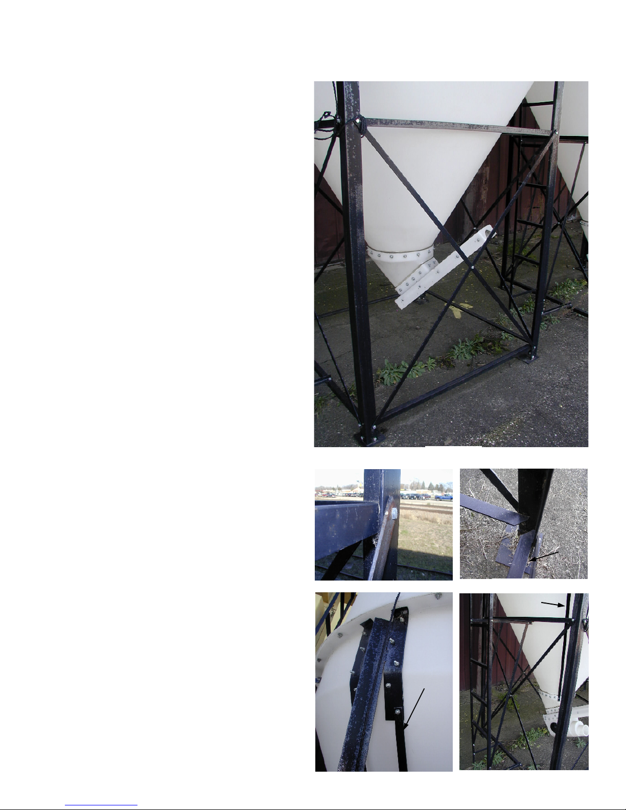
Note: If you are putting together a (2.5 Bin for
Mineral Concentrate) or 3.5 Ton Bin you will
need to install the extra support straps. They are 1”
X 51 1/4” long. You will need to put them on the
lowest bolt of the leg tabs. (2 Per Leg) They will
fasten to the slide valve bolts later on in the assembly (Diagram & 2A)
Diagram 1A
Diagram 1B
Mineral
Strap
Mineral
Strap
Leg
Pad
Diagram 2
Diagram 2A
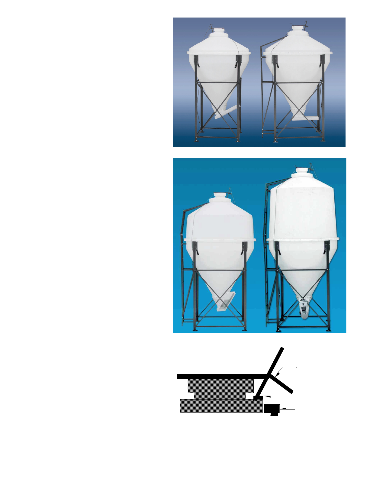
.9 Ton & 1.5 Ton Top Assembly: Diagram – 3
Place the cover over the top of the cone and
center it to the cone. (As shown in diagram-3)( If
the Lip of the Cone is to big you Will Need to Trim
the Lip of the Cone Off Slightly to make it fit
properly)
Now drill 24 - 5/16” holes evenly spaced
around the outer edge of the top making sure to go
through the lip of the cone also. Now bolt the Top
in place using the 5/16 X 1 1/2” hex head bolts
with a rubber seal washer on it. Place the bolt into
the hole from the top down and place a 5/16” stan-
dard washer & nut on the bolt on the under side of
the lip.
(Be Careful Not To Over Tighten and Crush the
Washer )
2.5 & 3.5 Ton Top Section to Lower Cone
Diagram - 4
Place the Top Section on the cone that is
mounted in the legs. Center the Top Section on the
lower cone
(If the Lip of the Cone is to big you Will
Need to Trim the Lip of the Cone Off Slightly to
make it fit properly)
Now drill 24 – 5/16” holes through the lip
making sure to go through the lip on the lower
cone. Space the holes space the holes evenly apart,
Bolt the top section in place using the 5/16 X 1
1/2” hex headed bolts. You need to place the seal
washers on these bolts, put the bolt with the seal
washer through from the top, put a regular 5/16
washers and nuts on from the bottom.
(Be Careful Not To Over Tighten and Crush the
Washer )
Cover Assembly all bins: Diagram –5
Hold the cover opener on the cover so the 2
bolts that are in the cover already are on each side
of the opener. Flush the lower mounting angle with
the edge of the cover. (figure AA)
Drill the 3-5/16” holes in the opener through the
cover, Use 2 - 5/16 X 1” carriage bolts and 1 – 5/16
X 3/4” from the inside out to fasten the opener to the
cover.
Now center the middle of the hinge to the
cover opener and line the bottom of the hinge up
with the bottom edge of the cover. Drill the 2-5/16”
holes in the hinge through the cover. Use 2- 5/16 X
3/4” carriage bolts again from the inside out to fasten
the hinge to the cover.
Next center the cover over the opening in the top of the bin. Hold the hinge down to the top of the bin
and drill the 2- 5/16” holes in the hinge through the plastic and than bolt the cover in place using 2-5/16 X 3/4”
.9
2.5
1.5
Diagram 3
3.5
Diagram 4
Cover Opener
AA
Hinge
Diagram - 5
 Loading...