

Page 1

PRSL Series IV Slushie Machine
User Manual
[Revision 2.0 July 2017]
READ THIS MANUAL CAREFULLY BEFORE USE – FAILURE TO DO SO MAY RESULT IN INJURY, PROPERTY
DAMAGE AND MAY VOID WARRANTY. • KEEP THIS MANUAL FOR FUTURE REFERENCE. • Products covered by
this manual may vary in appearance, assembly, inclusions, specifications, description and packaging.
E&OE ©2017 Polycool
Page 2

PRSL Series IV Slushie Machine
E&OE ©2017 Polycool 2
Safety
Safety messages are designed to alert you to possible dangers or hazards that could cause death, injury or
equipment or property damage if not understood or followed. Safety messages have the following symbols:
You WILL be KILLED or
SERIOUSLY INJURED if you
do not follow instructions.
You CAN be KILLED or
SERIOUSLY INJURED if you
do not follow instructions.
You CAN be INJURED if you
do not follow instructions or
equipment damage may occur.
It is important that you read and
understand the instruction manual before
use and keep the manual in a safe place
for future reference. Safety information
presented here is generic in nature –
some advice may not be applicable to
every piece of equipment.
All safety precautions must be observed
to reduce the risk of personal injury when
operating the equipment.
The term “equipment" refers to your
product, be it electrical mains, battery or
petrol engine powered.
IMPORTANT – Handle the equipment
safely and carefully.
BEFORE USE - If you are not familiar
with the safe operation/handling of this
equipment, or are in any way unsure of
any aspect of suitability or correct use it
for your application, you should complete
training conducted by a person or
organization qualified in safe use and
operation of this equipment.
• Read all safety warnings and
instructions. Failure to follow
warnings and instructions may result
in electric shock, fire and/or serious
injury.
• Do not operate the equipment in
flammable or explosive
environments, such as in the
presence of flammable liquids, gases
or dust.
• Keep clear of moving parts.
• This equipment may be a potential
source of electric shock if misused.
• Do not operate the equipment if it is
damaged, malfunctioning or is in an
excessively worn state.
• When using the equipment, basic
safety precautions detailed here
must always be followed to reduce
the risk of fire, electric shock,
personal injury and material damage.
• When wiring electrically powered
equipment, follow all electrical and
safety codes.
• Ensure all power sources conform to
equipment voltage requirements and
are disconnected before connecting
equipment.
• The equipment must be plugged into
a standard, earthed mains electrical
outlet. Do not plug into double
adaptors or multi-outlet extension
power boards.
• Children should be under adult
supervision whilst using the
machine.
Personal Safety
Keep packaging away from children - risk
of suffocation! Operators must use the
equipment correctly. When using the
equipment, consider conditions and pay
due care to persons and property.
Prevent unintentional starting of the
equipment - ensure equipment and power
source switches are in the OFF position
before connecting or moving the
equipment. Do not carry equipment with
hands/fingers touching any controls.
Remove any tools or other items that are
not a part of the equipment from it before
starting or switching on.
General Equipment Use and Care
Do not force the equipment. Use the
correct equipment for your application.
The correct equipment will perform better
and be safer within its design parameters.
Do not use the equipment if the ON/OFF
switch malfunctions – any equipment that
cannot be controlled with the ON/OFF
switch is dangerous and must be
repaired.
General Service Information
• Have the equipment serviced or
repaired at authorized service
centers by qualified personnel only.
• Replacement parts must be original
equipment manufacturer (OEM) to
help ensure that equipment safety is
maintained.
• Do not attempt any maintenance or
repair work not described in this
instruction manual.
• After use, the equipment and
components may still be hot – allow
the equipment to cool and
disconnect spark plugs and/or
electrical power sources and/or
batteries from it before making
adjustments, changing accessories
or performing repair or maintenance.
• Do not make adjustments while the
equipment is running.
• Perform all service related activities
under suitable conditions, such as a
workshop etc.
• Replace any worn, damaged or
missing warning labels immediately.
• Do not clean equipment with
solvents, flammable liquids or harsh
abrasives.
Slushie Machine Use and Care
WARNINGS
• Use only potable (drinkable) water in
the machine.
• Do not place body parts or any
object other than the recommended
liquids into the drink tanks while the
machine is running.
• Use only recommended liquids and
at the correct mixture ratio in the
drink tanks. Failure to follow to this
warning can result in serious
personal injury, death and/or
property damage.
• Do not operate the machine without
liquid in the drink tanks.
• Operate the machine on solid, level
surfaces only.
• At least 30cm (12”) free space
around the machine is required to
prevent machine overheating.
• Do not operate the machine in direct
sunlight or near heat generating
equipment.
Always clean all machine components
that come into contact with the drink
mixture thoroughly with food grade
disinfectant or mild detergent and warm
water. This must be done:
• Before first use.
• Weekly whilst the machine is in use.
• Before placing the machine into
storage.
• When commissioning the machine
after being in storage.
If an ice crust forms on the surface of
liquid in the drink tanks when the beater
(auger or spiral) has been off for an
extended period, it should be removed
before turning on the mixer.
Failure to follow the recommended
maintenance schedule may lead to
conditions or damage that will void any
product warranty.
Page 3

PRSL Series IV Slushie Machine
E&OE ©2017 Polycool 3
Table of Contents
Safety ............................................................................................................................................. 2
Applicable Models ........................................................................................................................ 4
Parts Identification ........................................................................................................................ 5
Assembly ....................................................................................................................................... 6
Operation ....................................................................................................................................... 7
Using the Tank Controls for Slush and Juice Modes ................................................................................... 7
Adjusting Tank Temperature ........................................................................................................................ 8
Filling the Tanks ........................................................................................................................................... 8
Adjusting Slush Consistency ........................................................................................................................ 9
Emptying Drip Trays ..................................................................................................................................... 9
Maintenance ................................................................................................................................ 10
Maintenance Schedule ............................................................................................................................... 10
Cleaning ..................................................................................................................................................... 10
Compressor Servicing ................................................................................................................................ 13
Seal Replacement ...................................................................................................................................... 13
Transportation and Storage ....................................................................................................................... 13
Troubleshooting .......................................................................................................................... 14
Specifications ............................................................................................................................. 15
PRSL-3000 ................................................................................................................................................. 15
PRSL-4500 ................................................................................................................................................. 15
Fill and Clean Quick Reference .................................................................................................. 17
Page 4

PRSL Series IV Slushie Machine
PRSL-3000 Series IV [ICESLHPLYA24L] Twin Tank
PRSL-4500 Series IV [ICESLHPLYA36L] Triple Tank
Applicable Models
This manual applies to the following Polycool slushie machines:
E&OE ©2017 Polycool 4
Page 5

PRSL Series IV Slushie Machine
No.
Name
No.
Name
1
Machine Body
7
Dispenser Handle Pivot Pin (1 per tank)
2
Control Panel
8
Dispenser Plunger (1 per tank)
3
Tank
9
Cooling Drum (1 per tank)
4
Tank Cover/Light Box (1 per tank)
10
Beater (1 per tank)
5
Dispenser Handle (1 per tank)
11
Drip tray (1 per tank)
6
Plunger Spring (1 per tank)
2
1 4 106 8 7 5 9 3
11
Parts Identification
The slushie machine comes mostly assembled, with minor assembly required to make the machine ready for
operation. Some machine may include spare seals and seal lubricant (shown below), which can be installed
as required (see Maintenance).
It is strongly recommended that you familiarise yourself with all major components of the machine before
using it or performing any maintenance tasks.
Products detailed in this manual may vary in appearance, inclusions, description and packaging
from those shown or described. This section shows typical major components common to most
slushie machines.
E&OE ©2017 Polycool 5
Page 6

PRSL Series IV Slushie Machine
2 2 1
Fig. 1
Fig. 3
6
B
Fig. 4
C
7 9 8
5
4
A
3
Fig. 2
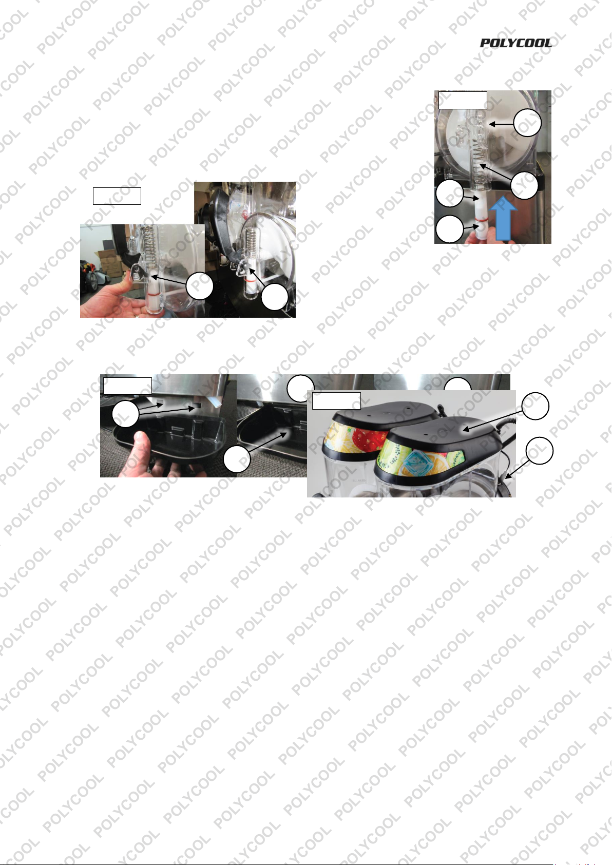
Assembly
The machine requires installation of the dispenser mechanisms and drip trays only. Before assembly, unpack
all items.
After assembly, the machine must be cleaned before being put into use (see Cleaning).
1. Position the machine with a gap of at least 30cm (12”) behind and to
the sides of it. This is to allow adequate ventilation and prevent
overheating of the machine.
2. See Fig. 1. Smear a small amount of food grade silicone lubricant onto
the dispenser plunger (1) O-ring (2). Check that the plug (3) at the
bottom of the dispenser plunger is fully seated (the plug does not
require lubricant).
3. See Fig. 2. For each tank, place a plunger spring (4) on the top of the
dispenser plunger (3). Ensure that the recess (A) in the plunger is facing
forward (the handle hooks into this), then push the plunger and spring into the
tank dispenser housing (5).
4. See Fig. 3. Whilst holding the plunger assembly in position, bring the handle
into position – the hook part of the handle (B) fits into the recess in the
plunger.
5. Secure the handle by pushing the handle pivot pin (6) through the flange on
the tank dispenser housing, through the handle and out again through the
opposite flange on the tank dispenser housing.
6. Perform steps 2 to 6 for each tank.
7. See Fig 4. Hook the drip tray (7) to the slots in the machine body (C).
8. Ensure that the drip tube (8) is in the drip tray, then place the tray cover (9) on to the drip tray.
9. Perform steps 8 to 9 for each tank.
E&OE ©2017 Polycool 6
Page 7

PRSL Series IV Slushie Machine
10
D
Fig. 5
10. See Fig. 5. Place the tank cover (10) into
position on the top of the tank.
11. Plug the tank cover cable (D) to the connector at
the rear of the machine.
12. Perform steps 11 to 12 for each tank.
Operation
Using the Tank Controls for Slush and Juice Modes
The machine has control panel on the side that allows you to individually
control each tank as required. There are two basic modes of operation:
• Juice Mode – Cools the drink solution, however, not to the point of
making ice.
• Slush Mode – Cools the drink solution to the point of being ice.
For each tank, there is a switch panel. When a switch is placed in the ON
position, the red lamp on the switch illuminates. For each set of switches,
the tank that they apply to is labelled next to the switches. The
configuration of switches determine the tank function, as follows:
Always place the beater switch in the ON position for either juice or slush mode. • For Slush mode,
place the slush mode switch in the ON position and the juice mode switch in the OFF position. • For
Juice mode, place the slush mode switch in the OFF position and the juice mode switch in the ON
position.
The machine compressor (cooling unit) and tank cover lights for all tanks are controlled by a single set of
“master” switches at the bottom of the control panel. When a switch is placed in the ON position, the red
lamp on the switch illuminates.
E&OE ©2017 Polycool 7
Page 8

PRSL Series IV Slushie Machine
1
3
2
Adjusting Tank Temperature
Note: The factory settings should be suitable for most uses. Adjust the thermostats only if required. If you
adjust the thermostat, it is recommended to monitor the change – is the solution at the right temperature? –
and adjust until the desired result is reached.
Each tank has a thermostat for setting the
“coldness” of the drink solution. Depending on
ambient temperatures (climate or operating
environment temperature), drink solution etc, the
coldness of the tanks may need adjusting for the
desired coldness and consistency of slush ice and
coldness of juice etc.
The tank thermostats (1) are located on the control
panel side of the machine, behind the plastic guard
(2). Use a Phillips head screwdriver to remove the
screw (3) fastening the guard. Gently pull the guard
out from the bottom edge until it unhooks from the
machine. The lower control is for the right-side tank,
the middle control is for the left-side tank on 2-tank
models or the middle tank for 3-tank models, the
upper control is for the left-side tank on 3-tank models. Left to right is taken when looking at the front of the
machine.
Rotate the thermostat knob as required – rotate right (clockwise) to increase coldness; rotate left (anticlockwise) to reduce coldness. It is recommended to not change the thermostat setting too much in a single
adjustment – make small changes and monitor the result. When finished adjusting, re-install the plastic
guard.
Filling the Tanks
Ensure that the drink solution is less than 35°C (95°F) when filling the tanks otherwise machine
damage may result. • Always mix the drink solution so that is a minimum of 13% sugar (ratio
approximately 6.5 parts water to 1 part sugar), otherwise the consistency of slush ice will be
incorrect and damage to machine may result. • Never allow the level of the drink solution to remain below the
minimum level or above the maximum level as machine damage may result. Failure to carry out the
procedures correctly may result in making the product warranty void.
1. Thoroughly mix the drink solution according to its instruction. Mix in a
container that is clean and suitable for handling food and drink for human
consumption.
2. Switch OFF the slush or juice mode switch and beater for the tank before
refilling. If you are filling all tanks, turn OFF the compressor using the “master”
switch.
3. Switch OFF the tank lights.
4. Unplug and remove the tank cover.
5. Carefully pour the mixture into the tank. Do not fill to less than the
“MIN LEVEL” indicator or over the “MAX LEVEL” indicators on the
front of the tank.
6. When finished filling, place the tank cover in position and re-connect
the cable. Reconnect the machine to the electricity supply if
previously unplugged. Switch ON the slush or juice mode switch and
beater for the tank or at the “master” switch. Switch ON the tank
lights.
E&OE ©2017 Polycool 8
Page 9

PRSL Series IV Slushie Machine
A B A
B
1
3
2
Adjusting Slush Consistency
The mixer speed controls the “thickness” of the drink solution in slush mode. The
faster the speed, the “thinner” the slush mixture; the slower the speed, the
“thicker” the slush mixture.
To adjust beater speed, use a flat blade screwdriver to rotate the adjustment
screw (A) at the rear of the tank as required. Rotate the screw to the right
(clockwise) to increase mixing speed and create a thinner slush consistency.
Rotate left (anti-clockwise) to decrease mixing speed and create a thicker slush
consistency. The relative speed is shown by the indicator (B) below the screw.
Note: Mixing speed adjustment should not be required for juice mode operation.
Emptying Drip Trays
Drip trays require regular emptying as a result of spillage, dripping etc. The drip
tray has a small coloured float (A) – when it protrudes from the drip tray, the tray
must be emptied. To remove a drip tray, unhook it from the slots in the machine.
To re-install a drip tray (1), hook it to the slots in the machine body (B). Ensure
that the drip tube (2) is in the drip tray, then place the tray cover (3) on top of the
drip tray.
E&OE ©2017 Polycool 9
Page 10

PRSL Series IV Slushie Machine
Fig. 7
1
A
Fig. 8
2
3
4
5
6
Fig. 9
Maintenance
Maintenance Schedule
Failure to follow the recommended maintenance schedule may lead to conditions or damage
that will void any product warranty.
The following schedule must be followed in order to keep the machine running efficiently and to maximise its
service life.
• Clean the tanks every week whilst the machine is in use.
• Check seals and O-rings during each tank clean – always replace worn or damaged seals.
• Clean the cooling fan and compressor heat exchanger at least once every 6 months.
• Always ensure there is at least 30cm (1’) behind and to the sides of the machine for ventilation.
Cleaning
Clean all machine components that come into contact with the drink solution with mild detergent or
food grade disinfectant and clean water. This must be done before first use and on a weekly basis
when the machine is in use. Cleaning should also be performed before placing the machine in
storage, and when commissioning the machine after being in storage. • When cleaning, do not immerse the
tank cover or any electrical components in water. • Do not use solvents, harsh detergents or abrasives for
cleaning as these may damage the machine. • The seal lubricant should be a food grade silicone type.
1. Switch OFF the slush or juice mode switch and beater for the tank before
cleaning. If you are cleaning all tanks, turn OFF the compressor using the
“master” switch and unplug the machine from the electricity supply.
2. Switch OFF the tank lights.
3. Disconnect the tank cover cable from the connector at the rear of the
machine.
4. Remove the tank cover. If the cover requires cleaning, use a damp cloth to
clean its surfaces. Clean the surface that sits above the drink solution
first. Do not immerse the tank cover in water.
5. Unhook and remove the drip tray.
6. Use the dispenser tap to drain the tank of any remaining drink solution.
Drain the liquid into a suitable container.
7. Fill the tank with hot (not boiling), clean water, then drain completely.
8. See Fig 7. Lift the front of the tank (1) enough for it to clear the lip at the
front of the machine (A) then gently pull it from the machine.
9. See Fig 8. Gently pull the beater (2) from its driveshaft
(3), then slide it off the cooling drum (4).
10. See Fig 9. Pull the driveshaft seal (5) from the end of the
beater (it may have remained attached to the end of the
driveshaft). Pull the tank seal (6) from the end of the
cooling drum. Inspect both seals for wear or damage
and replace if necessary.
E&OE ©2017 Polycool 10
Page 11

PRSL Series IV Slushie Machine
Fig. 12
3
1
Fig. 11
2
4
Fig. 13
4
5
2
Fig. 14
Fig. 15
6
A
8 9 7
Fig. 16
Fig. 10
7
8 B 9
10
11
11. See Fig 10. Pull the handle pivot pin (7) from the tank and remove it and
the handle (8). The dispenser plunger (9) should drop from the tank
dispenser housing – if it remains in place, use an object to push it down
from the hole (B) at the top of the housing. Remove the O-ring (10) and
rubber end plug (11) from the plunger for cleaning. Inspect the O-ring and
rubber end plug for wear or damage and replace if necessary
12. Thoroughly clean all tank parts in warm, clean water and food grade
disinfectant or mild detergent, then rinse several times with hot water.
Note: Do not use solvents, harsh detergents or abrasive cleaners. • When
cleaning in a sink, use the sink plug or a strainer to prevent losing small
parts through the drain hole.
13. Use paper towel to wipe away any residual lubricant on the cooling drum
where the seals are located (around the mixer driveshaft and back of the
cooling drum).
14. Using warm water and a clean cloth, thoroughly clean the cooling drum
and the machine body beneath the tanks.
15. Clean the drain tube using a suitable pipe cleaner or similar. Additionally, hot (not boiling) water can be
poured through the tubes to aid cleaning. Pour through the hole in the machine beneath the front of each
tank and use a suitable container to catch the water.
Once all parts are cleaned, rinsed and dry, reassemble
as follows:
1. See Fig 11. Place the tank seal (1) onto the cooling
drum. Ensure that the larger diameter side sits up
against the rear of the cooling drum (2) and that the
seal is properly seated all the way around and is not
twisted.
2. See Fig. 11. Insert the driveshaft seal (3) into the
end of the beater (4).
3. See Fig 12. Smear a small amount of food grade silicone lubricant onto the
cooling drum where the beater driveshaft protrudes.
4. See Fig 13. Slide the beater (4) onto the cooling drum (2). Ensure that the flat
part of the beater driveshaft (5) fits correctly into the end of the beater,
otherwise it will not install fully. When installing the beater, when it reaches the
end of the driveshaft, rotate it until you feel it engage with the “flat” (A) on the
driveshaft. Once the beater and driveshaft are properly aligned you will be able
to slide the beater fully into position. Do not force the beater on as this may
damage it. When properly installed, the driveshaft seal should be up against
the cooling drum.
5. See Fig 14. Smear a small amount of food
grade silicone lubricant all the way around
the end of the tank, where it comes into
contact with the tank seal.
6. See Fig 15. Slide the tank (6) over the
beater and cooling drum. Ensure it fits
snugly over the tank seal without pinching.
When fully seated, place a little downward
pressure at the front of the tank so that it
“clips” into position over the lip (A) at the front of the machine.
7. See Fig 16. Smear a small amount of food
grade silicone lubricant onto the dispenser
plunger (7) O-ring (8) and the sealing plug
(2) at the bottom of the dispenser plunger
(3).
E&OE ©2017 Polycool 11
Page 12
PRSL Series IV Slushie Machine
Fig. 19
D
19
21
20
11
10
B
7
Fig. 17
Fig. 18
12 C 22
E
Fig. 20
8. See Fig. 17. Place the plunger spring (10) on the top of the dispenser plunger (7). Ensure that the recess
(B) in the plunger is facing forward (the handle hooks into this), then push
the plunger and spring into the tank dispenser housing (11).
9. See Fig. 18. Whilst holding the plunger assembly in position, bring the
handle into position – the hook part of the handle (C) fits into the plunger
recess. Secure the handle by pushing the handle pivot pin (12) through the
flange on the tank dispenser housing, through the handle and out again
through the opposite flange on the tank dispenser housing.
10. See Fig 19. Hook the drip tray (19) to the slots in the machine body (D).
11. Ensure that the drip tube (20) is in the drip tray, then place the tray cover (21) on to the drip tray.
12. See Fig. 20. Place the tank cover (22) into
position on the top of the tank.
13. Plug the tank cover cable (E) to the connector at the rear of the machine.
14. Perform the above steps for each tank.
E&OE ©2017 Polycool 12
Page 13
PRSL Series IV Slushie Machine
4
2
1
3
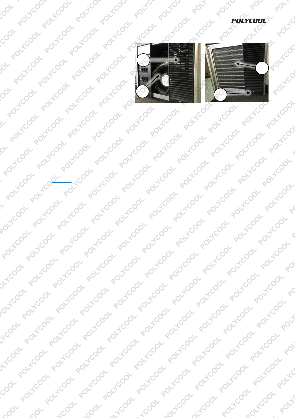
Compressor Servicing
Every 6 months, clean the cooling fan and
compressor heat exchanger fins of dirt and
dust to ensure best cooling efficiency of the
machine. Clean as follows:
1. Turn OFF the machine and disconnect it
from the electricity supply.
2. Use a Phillips head screwdriver to remove
the screws (1) fastening the plastic guards
(2) on either side of the machine. Gently
pull the guard out from the bottom edge until it unhooks from the machine.
3. Use a soft brush (such as a paintbrush) to remove any built up dust and dirt from the compressor cooling
fan (3) (this is located on the control panel side) and heat exchanger (4). When cleaning the heat
exchanger, brush up and down the fins, not across them.
4. When finished, re-install the plastic guards and secure with the screws. Do not over-tighten the screws.
Seal Replacement
Seals are essential to correct operation of the slushie machine. Leaks from the drink dispensers or the drip
tube is filling the drip tray often indicates faulty seals. Dispenser leaks indicate the dispenser O-ring may
need replacing. Excessive liquid through the drip tube indicates the tank seal may need replacing.
Follow the Cleaning procedure to remove and clean old seals and to install and lubricate new seals.
Transportation and Storage
• Drain the tanks and clean the machine (see Cleaning).
• Store the unit in a dry, well-ventilated area and out of the reach of children.
• Do not store in direct sunlight.
• Cover the machine to protect it from dirt and dust.
E&OE ©2017 Polycool 13
Page 14
PRSL Series IV Slushie Machine
Possible Fault
Action
No electrical supply
Check that mains electricity is available and the machine is properly connected to it.
Overload protector tripped
The machine overload protector has tripped due to overheating. The machine will switch on
again automatically once cooled. Ensure that the machine has enough space around it for
ventilation. Ensure that compressor cooling fan and heat exchanger are clean.
Possible Fault
Action
Cooling unit not ON
Ensure the compressor master switch is in the ON position.
Tank cooling switches not ON
Ensure the cooling mode switches are correctly set for slush or juice mode.
Tank thermostat not cool enough
Adjust thermostat to colder setting.
Possible Fault
Action
Machine not level
Ensure the machine is installed on a flat, level surface.
Drink solution lacks sugar
Correct the sugar to water ratio (6.5 parts water to 1 part sugar or 13% sugar minimum) of
the drink solution.
Possible Fault
Action
Dispenser not sealing
Check that dispenser is correctly assembled. Check O-ring for wear, dirt or damage – clean
or replace O-ring as required.
Tank not sealing
Check that tank seal and tank are correctly assembled. Check seal for wear, dirt or damage
– clean or replace seal as required.
Troubleshooting
Some maintenance activities described may be beyond the scope of some users. For procedures
that you are not comfortable with or have the tools or experience for, have the unit serviced by a
service center or qualified technician.
The following information may assist in identifying a problem and rectifying it.
Note: Some procedures listed here may need to be performed by a service center or qualified
technician. • If problems persist after following all suggested actions, contact a service center or
qualified technician.
Machine not operating.
Machine runs, but not cooling drink mixture.
Machine runs and cools, but vibrates, clicks on and off or is noisy.
Drips trays filling and/or dispensers leaking.
E&OE ©2017 Polycool 14
Page 15

PRSL Series IV Slushie Machine
Input Voltage
240VAC / 50Hz
Current Consumption
5.8A
Drink Tank Capacity
2 x 12l
Drink Tank Temperature
-4 to -2°C (24.8 to 28.4°F)
Refrigerant Agent
R134a / 400g
Frothing Agent
HCFC-141b
Ambient Operating
Temperature Range
5 to 35°C (41 to 95°F)
Humidity
90% maximum
Weight
Approximately 65kg without liquids
Input Voltage
240VAC / 50Hz
Current Consumption
5.4A
Drink Tank Capacity
3 x 12l
Drink Tank Temperature
-4 to -2°C (24.8 to 28.4°F)
Refrigerant Agent
R404a / 480g
Frothing Agent
HCFC-141b
Ambient Operating
Temperature Range
5 to 35°C (41 to 95°F)
Humidity
90% maximum
Weight
Approximately 46kg without liquids
Specifications
PRSL-3000
PRSL-4500
E&OE ©2017 Polycool 15
Page 16

PRSL Series IV Slushie Machine
E&OE ©2017 Polycool 16
Some experts believe the incorrect or prolonged use of almost any product could cause serious
injury or death. For information that may reduce your risk of serious injury or death, consult the
points below and additionally, the information available at www.datastreamserver.com/safety
• Consult all documentation, packaging and product
labelling before use. Note that some products feature
online documentation which should be printed and kept
with the product.
• Check product for loose / broken / damaged / missing
parts, wear or leaks (if applicable) before each use.
Never use a product with loose / broken / damaged /
missing parts, wear or leaks (if applicable).
• Products must be inspected and serviced (if applicable)
by a qualified specialist every 6 months assuming
average residential use by a person of average weight
and strength, above average technical aptitude, on a
property matching average metropolitan specification.
Intended use outside these guidelines could indicate
the product is not suitable for intended use or may
require more regular inspection or servicing.
• Ensure all possible users of the product have
completed an industry recognized training course
before being given access to the product.
• The product has been supplied by a general merchandise retailer that
may not be familiar with your specific application or your description
of the application. Be sure to attain third-party approval for your
application from a qualified specialist before use regardless of prior
assurances by the retailer or its representatives.
• This product is not intended for use where fail-safe operation is
required. As with any product (take an automobile, aircraft, computer
or ball point pen for example), there is always a small chance of
technical issues that needs to be repaired or may require replacement
of the product or a part. If the possibility of such failure and the
associated time it takes to rectify could in any situation inconvenience
the user, business or employee then the product is not suitable for
your requirements. This product is not for use where incorrect
operation or a failure of any kind, including but not limited to a
condition requiring product return, replacement, service by a
technician or replacement of parts could cause a financial loss, loss of
employee time or an inconvenience requiring compensation.
• If this item has been purchased in error after considering the points
above, simply contact the retailer directly for details of their returns
policy, if required.
©2017 Polycool. All rights reserved. No part of this document, including descriptive content, concepts, ideas,
diagrams or images may be reproduced or transmitted in any form or by any means, electronic or
mechanical, including photocopying, scanning or recording, or any information storage and retrieval system,
without express permission or consent from the publisher.
Page 17

PRSL Series IV Slushie Machine
E&OE ©2017 Polycool 17
Fill and Clean Quick Reference
It is recommended to print this page, laminate it and attach it to the machine for easy reference. For
further information on the following procedures, read the manual.
Drink Solution Mixing and Tank Filling
Water to sugar ratio of drink solution must be a minimum 13% sugar.
That is, 6.5 parts water to 1 part sugar. Incorrect ratios will either cause
the drink solution to be too icy (not enough sugar) or not icy enough (too
much sugar).
Never allow the drink solution level to exceed the maximum level
mark or fall below the minimum level mark.
• Thoroughly mix the drink solution in a suitable container (1).
• Turn OFF the beater and compressor (2).
• Unplug tank cover and remove (3).
• Fill tank to “MAX LEVEL” (4).
• Install tank cover and plug in (3).
• Turn ON beater and compressor (2).
Tank Cleaning
Tanks must be cleaned weekly using food grade disinfectant or mild
detergent. Seal lubricant must be food grade silicone.
• Turn OFF the beater and compressor (1).
• Remove drip tray (2).
• Empty tank of drink solution (3).
• Unplug tank cover and remove (4).
• Rinse tank with hot water (5).
• Drain tank (6).
• Lift front edge of tank to clear lip at front of machine, then pull off (7).
• Pull beater (8) from driveshaft (9).
• Remove driveshaft seal (10).
• Remove tank seal (11).
• Disassemble tap dispenser (12) (handle, pin, spring, plunger, O-ring,
plunger end plug).
• Clean and rinse all parts thoroughly (13).
• Install tank seal (14).
• Lubricate cooling drum around driveshaft (15).
• Insert driveshaft seal (16) to end of beater (17), then push beater onto
driveshaft.
• Lubricate tank around tank seal (18), then push tank firmly over tank
seal then push down until tank “clicks” into position (19).
• Reassemble dispenser plunger and
lubricate O-ring (20), then re-install
dispenser (21).
• Re-install drip tray (22).
• Fill tank (see above).
 Loading...