

Page 1
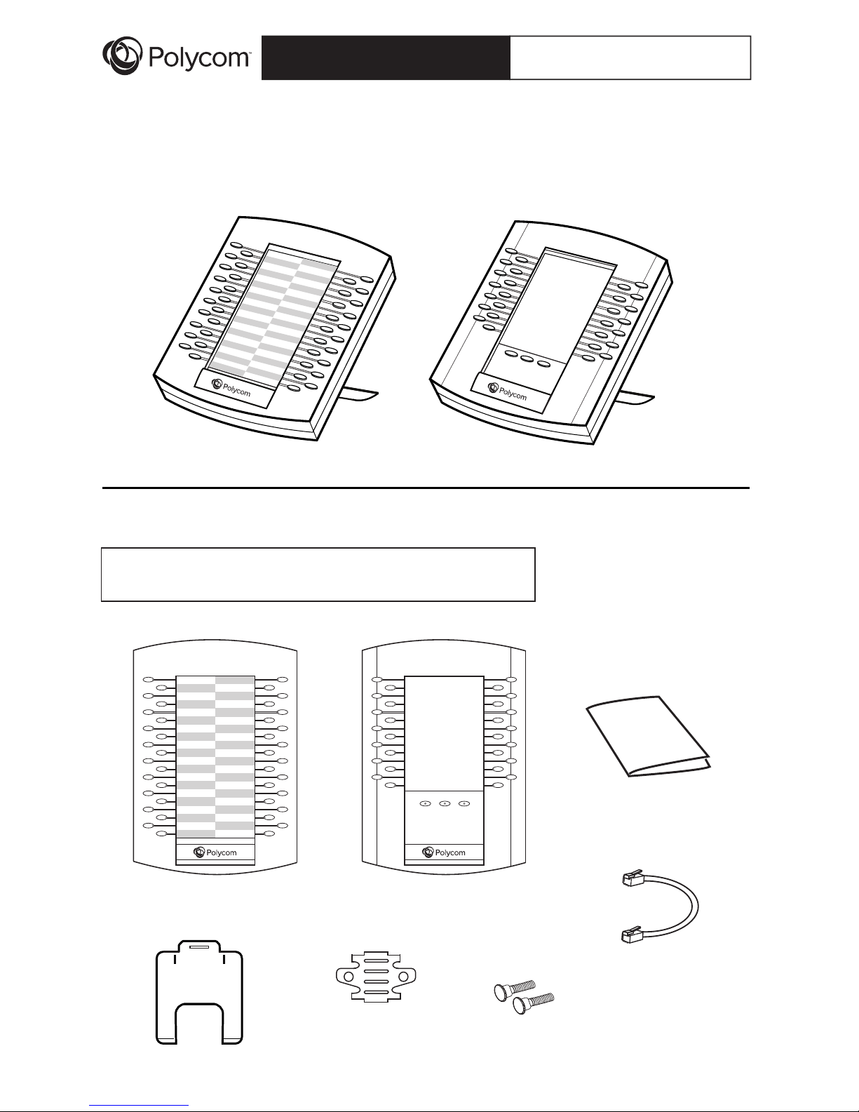
Package Contents
VVX Expansion Module
Cable Connector
Quick Start Guide
®
VVX Expansion Module
Quick Start Guide
Base Stand
® ®
Polycom VVX
Expansion Module
® ®
Polycom VVX Color
Expansion Module
VVX Color Expansion Module
Note: The package will contain either a VVX Expansion
Module, or a VVX Color Expansion Module.
Metal Bracket
Two Thumb Screws
Page 2
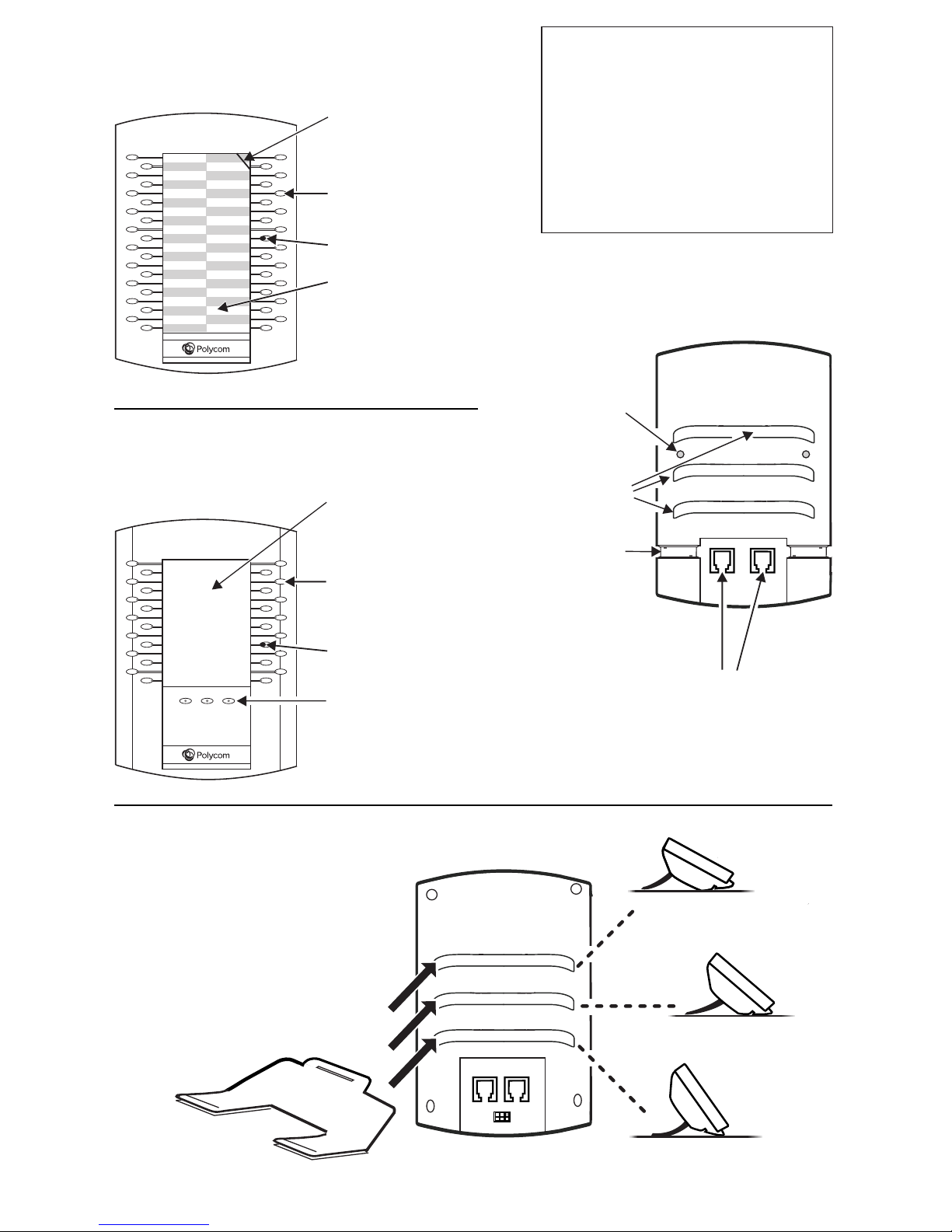
Connecting the Base Stand*
Fully insert the stand into
one of the slots on the
back of the Expansion
Module. The slot you
choose determines the
angle of the Expansion
Module. The phone and
Expansion Module should
be at the same angle.
*For wallmount installation, an optional accessory is available. For more information, contact your
reseller.
VVX Color Expansion Module
Features
VVX Expansion Module Features
Back
(either model)
AUX 1AUX 2
Auxiliary Ports. Connect the
Cable Connector to one of
these ports, and to an Auxiliary
Port on the phone or another
Expansion Module.
Cable groove
(one on each side) to
hold Cable Connector
in place
Slots for
base stand
Line Keys
LED Indicators
Plastic cover overlaying
paper template.
Write phone lines, presence
contacts or speed dials
on the template.
Cut out in cover for
cover removal
Line Keys
LED Indicators
Page Keys. Press a
page key to display
more Line Keys.
Color Display
Note: The paper module has a plastic
cover that overlays a paper template.
To remove or insert the template, place
the tip of a paperclip under the slot at
the top-right corner of the cover, lift the
cover off, and remove or insert the
template. To re-attach the cover, align
the six tabs on either side of the cover
with the corresponding indents on the
Expansion Module, and bend the cover
into place.
Holes for
thumb screws
(one on each side)
to anchor metal bracket
Page 3

Installing and Starting Up
2
4
To connect another Expansion Module, attach another Cable Connector between the
AUX 2 port on the first Expansion Module and the AUX 1 port on the second
Expansion Module. You can connect a maximum of three Expansion Modules to one
phone, as shown next.
Turn the phone and Expansion Module upside down on the table. Insert the Cable
Connector between the AUX port on the phone, and the AUX 1 port on the
Expansion Module. Thread the cable through the Cable Grooves on the Expansion
Module and phone. If the phone is connected to the network, the Expansion Module
will automatically power on and start up.
5
Position the phone and Expansion Module next to each other on a flat, level surface.
Position them as closely together as you can. Then, locate the holes for the thumb
screws; the holes are located between the top-most and middle stand slot.
1
Connect the base stand to your Expansion Module at the same angle as your
phone’s stand.
3
Hold the metal bracket so that the four tabs face away from you, and the arrow on
the back of the bracket points up. Position the holes in the metal bracket over the
thumb screw holes. The four tabs on the bracket fit in the top-most and middle stand
slots. Insert the thumb screws in the holes, and finger tighten.
Metal
Bracket
AUX 1AUX 2
48V
LAN
HEADSET
HANDSET
PC
AUX
Back of
VVX Phone
Back of
VVX Phone
Holes for
thumb screws.
Position holes in
metal bracket
over these holes.
Middle
stand slot
Back of
Expansion
Module
Back of
Expansion
Module
Page 4

1725-49101-001
F
http://www.polycom.com
Contact Information:
Please contact your Polycom Authorized Reseller for assistance.
SAFETY AND REGULATORY INFORMATION. This device complies with Part 15
of the FCC Rules. Operation is subject to the following two conditions:
(1) This device may not cause harmful interference, and (2) This device must
accept any interferences received, including interference that may cause
undesired operation.
NOTE: This equipment has been tested and found to comply with the limits for a
Class A digital device, pursuant to part 15 of the FCC Rules. These limits are
designed to provide reasonable protection against harmful interference when the
equipment is operated in a commercial environment. This equipment generates,
uses, and can radiate radio frequency energy and, if not installed and used in
accordance with the instruction manual, may cause harmful interference to radio
communications. Operation of this equipment in a residential area is likely to
cause harmful interference in which case the user will be required to correct the
interference at his own expense.
Hereby, Polycom, Inc. declares that the products in this manual are CE marked
and in compliance with all EU directives and regulations that apply to them
including: LVD & EMC Directives 2014/35/EC & 2014/30/EC. A full copy of the
Declaration of Conformity can be obtained from Polycom Ltd., 270 Bath Road,
Slough, Berkshire, SL1 4DX, UK.
In accordance with Part 15 of the FCC Rules, the user is cautioned that any
changes or modifications not expressly approved by Polycom, Inc. could void the
user’s authority to operate the equipment.
Operating Ambient Conditions:
Operating temperature: +32 to 104°F (0 to 40°C);
Relative humidity: 5% to 95%, noncondensing;
Storage temperature: -40 to +160°F (-40 to +70°C).
Installation must be performed in accordance with all relevant national wiring
rules.
L’Installation doit être exécutée conformément à tous les règlements nationaux
applicable au filage électrique.
The outlet to which this apparatus is connected must be installed near the
equipment and must always be readily accessible.
La prise électrique à laquelle l’appareil est branché doit être installée près de
l’équipement et doit toujours être facilement accessible.
This Class [A] digital apparatus complies with Canadian ICES-003.
Cet appareil numérique de la classe [A] sera conforme à la norme NMB-003 du
Canada.
To avoid electric shock, do not connect safety extra low voltage (SELV) circuits to
teleconference station network (TNV) circuits. LAN ports contain SELV circuit, and
WAN ports contain TNV circuits. Some LAN and WAN ports both use RJ-45
connectors. Use caution when connecting cables. This product is rated 48Vdc,
0.38A.
Afin d’éviter les chocs électriques, ne pas connecter de circuits de tension
extra-basse de sécurité (SELV) à des circuits de réseau de stations de
téléconférence (TNV). Les ports LAN contiennent un circuit SELV et les ports
WAN contiennent des circuits TNV. Certains ports LAN et WAN utilisent tous
deux des connecteurs RJ-45. Faites preuve de prudence lors de la connexion
des câbles. Ce produit a les caractéristiques suivantes : 48 Vdc, 0,38 A.
In addition, all PoE sources must meet the Limited Power Source requirements
of IEC 60950-1:2005 (2nd Edition); Am1:2009 or IEC 60950-1:2005 (2nd
Edition); Am1:2009; Am2:2013.
En outre, toutes les sources PoE doivent satisfaire aux exigences de source
d'alimentation limitée de la IEC 60950-1:2005 (2ème édition); Am1:2009 ou
IEC 60950-1:2005 (2ème édition); Am1:2009; Am2:2013.
Japan:
LIMITED WARRANTY. Polycom warrants to the end user (“Customer”) that this
product will be free from defects in workmanship and materials, under normal
use and service, for one year from the date of purchase from Polycom or its
authorized reseller. Polycom’s sole obligation under this express warranty shall
be, at Polycom’s option and expense, to repair the defective product or part,
deliver to Customer an equivalent product or part to replace the defective item,
or if neither of the two foregoing options are reasonably available, Polycom
may, on its sole discretion, refund to Customer the purchase price paid for the
defective product. All products that are replaced will become the property of
Polycom. Replacement products or parts may be new or reconditioned.
Polycom warrants any replaced or repaired product or part for ninety (90) days
from shipment, or the remainder of the initial warranty period, whichever is
longer. Products returned to Polycom must be sent prepaid and packaged
appropriately for safe shipment, and it is recommended that they be insured or
sent by a method that provides for tracking of the package. Responsibility for
loss or damage does not transfer to Polycom until the returned item is received
by Polycom. The repaired or replaced item will be shipped to Customer, at
Polycom’s expense, not later than thirty (30) days after Polycom receives the
defective product, and Polycom will retain risk of loss or damage until the item
is delivered to Customer.
EXCLUSIONS. Polycom will not be liable under this limited warranty if its
testing and examination disclose that the alleged defect or malfunction in the
product does not exist or results from:
Failure to follow Polycom’s installation, operation, or maintenance
instructions.
Unauthorized product modification or alteration.
Unauthorized use of common carrier communication services accessed
through the product.
Abuse, misuse, negligent acts or omissions of Customer and persons under
Customer’s control;
or
Acts of third parties, acts of God, accident, fire, lightening, power surges or
outages, or other hazards.
WARRANTY EXCLUSIVE. IF A POLYCOM PRODUCT DOES NOT OPERATE
AS WARRANTED ABOVE, CUSTOMER’S SOLE REMEDY FOR BREACH OF
THAT WARRANTY SHALL BE REPAIR, REPLACEMENT, OR REFUND OF
THE PURCHASE PRICE PAID, AT POLYCOM’S OPTION. TO THE FULL
EXTENT ALLOWED BY LAW, THE FOREGOING WARRANTIES AND
REMEDIES ARE EXCLUSIVE AND ARE IN LIEU OF ALL OTHER
WARRANTIES, TERMS, OR CONDITIONS, EXPRESS OR IMPLIED, EITHER
IN FACT OR BY OPERATION OF LAW, STATUTORY OR OTHERWISE,
INCLUDING WARRANTIES, TERMS, OR CONDITIONS OF
MERCHANTABILITY, FITNESS FOR A PARTICULAR PURPOSE,
SATISFACTORY QUALITY, CORRESPONDENCE WITH DESCRIPTION, AND
NON-INFRINGEMENT, ALL OF WHICH ARE EXPRESSLY DISCLAIMED.
POLYCOM NEITHER ASSUMES NOR AUTHORIZES ANY OTHER PERSON
TO ASSUME FOR IT ANY OTHER LIABILITY IN CONNECTION WITH THE
SALE, INSTALLATION, MAINTENANCE OR USE OF ITS PRODUCTS.
SERVICE AGREEMENTS. Please contact your Polycom Authorized Reseller
for information about service agreements applicable to your product.
SOFTWARE SUPPORT. Polycom will provide support for software running on
the Product if all of the following conditions are satisfied:
The product is under warranty or is covered by a Polycom service contract;
The product software is the current major version or the next preceding major
version (software
revisions are labeled as “x.y.z,” with the first two digits designating major
versions).
The product software comes with 90-day software warranty, providing for
software updates (minor releases/bug fixes). To continue to receive support,
purchasing a maintenance contract is the most economical solution.
Requests for software support should be made through the Polycom Reseller
from whom the product was purchased.
LIMITATION OF LIABILITY. TO THE FULL EXTENT ALLOWED BY LAW,
POLYCOM EXCLUDES FOR ITSELF AND ITS SUPPLIERS ANY LIABILITY,
WHETHER BASED IN CONTRACT OR TORT (INCLUDING NEGLIGENCE),
FOR INCIDENTAL, CONSEQUENTIAL, INDIRECT, SPECIAL, OR PUNITIVE
DAMAGES OF ANY KIND, OR FOR LOSS OF REVENUE OR PROFITS,
LOSS OF BUSINESS, LOSS OF INFORMATION OR DATA, OR OTHER
FINANCIAL LOSS ARISING OUT OF OR IN CONNECTION WITH THE SALE,
INSTALLATION, MAINTENANCE, USE, PERFORMANCE, FAILURE, OR
INTERRUPTION OF ITS PRODUCTS, EVEN IF POLYCOM OR ITS
AUTHORIZED RESELLER HAS BEEN ADVISED OF THE POSSIBILITY OF
SUCH DAMAGES, AND LIMITS ITS LIABILITY TO REPAIR, REPLACEMENT,
OR REFUND OF THE PURCHASE PRICE PAID, AT POLYCOM’S OPTION.
THIS DISCLAIMER OF LIABILITY FOR DAMAGES WILL NOT BE AFFECTED
IF ANY REMEDY PROVIDED HEREIN SHALL FAIL OF ITS ESSENTIAL
PURPOSE.
DISCLAIMER. Some countries, states, or provinces do not allow the exclusion
or limitation of implied warranties or the limitation of incidental or consequential
damages for certain products supplied to consumers, or the limitation of liability
for personal injury, so the above limitations and exclusions may be limited in
their application to you. When the implied warranties are not allowed to be
excluded in their entirety, they will be limited to the duration of the applicable
written warranty. This warranty gives you specific legal rights which may vary
depending on local law.
GOVERNING LAW. This Limited Warranty and Limitation of
Liability shall be governed by the laws of the State of California,
U.S.A., and by the laws of the United States, excluding their
conflicts of laws principles. The United Nations Convention on
Contracts for the International Sale of Goods is hereby excluded
in its entirety from application to this Limited Warranty and
Limitation of Liability. All rights reserved under International and
Pan American Copyright Conventions. No part of the contents of
this manual may be copied, reproduced, or transmitted in any
form or by any means, or translated into another language or
format, in whole or part, without written consent from Polycom,
Inc. Do not remove (or allow anybody else to remove) any product
identification, copyright or other notices. Polycom, the Polycom
logo design, and Polycom VVX Expansion Module and Polycom
VVX Color Expansion Module are trademarks of Polycom, Inc. in
the U.S. and various other countries.
COPYRIGHT. All rights reserved under International and PanAmerican Copyright Conventions. No part of the contents of this
manual may be copied, reproduced, or transmitted in any form or
by any means, or translated into another language or format, in
whole or part, without written consent of Polycom, Inc. Polycom®
and the logo design are registered trademarks and Polycom VVX
Expansion Module and Polycom VVX Color Expansion Module
are trademarks of Polycom, Inc. in the United States, and various
countries. Do not remove (or allow any third party to remove) any
product identification, copyright or other notices.
Copyright, Safety Notices
Regulatory Notice: https://support.polycom.com/content/dam/polycomsupport/products/voice/business-media-phones/other-documents/en/safetyreg-note.pdf
 Loading...