

Page 1
Design Guide
for the Polycom SoundStructure
C16, C12, C8, and SR12
3725-33186-001
Revision: B
Page 2

Trademark Information
Polycom®, the Polycom logo design, and Vortex® are registered trademarks of Polycom, Inc., and Global Management
System™, MGC™, People+Content™, People On Content™, Polycom InstantDesigner™, Polycom PathNavigator™,
PowerCam™, Siren™, and VSX® are trademarks of Polycom, Inc. in the United States and various other countries.
VISCA is a trademark of Sony Corporation. All other trademarks are the property of their respective owners.
Patent Information
The accompanying product is protected by one or more U.S. and foreign patents and/or pending patent applications
held by Polycom, Inc.
Disclaimer
Some countries, states, or provinces do not allow the exclusion or limitation of implied warranties or the limitation of
incidental or consequential damages for certain products supplied to consumers, or the limitation of liability for personal
injury, so the above limitations and exclusions may be limited in their application to you. When the implied warranties
are not allowed to be excluded in their entirety, they will be limited to the duration of the applicable written warranty. This
warranty gives you specific legal rights which may vary depending on local law.
Copyright Notice
Permission is hereby granted, free of charge, to any person obtaining a copy of this software and associated
documentation files (the "Software"), to deal in the Software without restriction, including without limitation the rights to
use, copy, modify, merge, publish, distribute, sublicense, and/or sell copies of the Software, and to permit persons to
whom the Software is furnished to do so, subject to the following conditions:
The above copyright notice and this permission notice shall be included in all copies or substantial portions of the
Software.
THE SOFTWARE IS PROVIDED "AS IS", WITHOUT WARRANTY OF ANY KIND, EXPRESS OR IMPLIED,
INCLUDING BUT NOT LIMITED TO THE WARRANTIES OF MERCHANTABILITY, FITNESS FOR A PARTICULAR
PURPOSE AND NONINFRINGEMENT. IN NO EVENT SHALL THE AUTHORS OR COPYRIGHT HOLDERS BE
LIABLE FOR ANY CLAIM, DAMAGES OR OTHER LIABILITY, WHETHER IN AN ACTION OF CONTRACT, TORT OR
OTHERWISE, ARISING FROM, OUT OF OR IN CONNECTION WITH THE SOFTWARE OR THE USE OR OTHER
DEALINGS IN THE SOFTWARE.
© 2007 Polycom, Inc. All rights reserved.
Polycom Inc.
4750 Willow Road
Pleasanton, CA 94588-2708
USA
No part of this document may be reproduced or transmitted in any form or by any means, electronic or mechanical, for
any purpose, without the express written permission of Polycom, Inc. Under the law, reproducing includes translating
into another language or format.
As between the parties, Polycom, Inc. retains title to, and ownership of, all proprietary rights with respect to the software
contained within its products. The software is protected by United States copyright laws and international treaty
provision. Therefore, you must treat the software like any other copyrighted material (e.g. a book or sound recording).
Every effort has been made to ensure that the information in this manual is accurate. Polycom, Inc. is not responsible
for printing or clerical errors. Information in this document is subject to change without notice.
Page 3

Contents:
1 Introduction . . . . . . . . . . . . . . . . . . . . . . . . . . . . . . . . . . . . . . . . . 1–1
2 SoundStructure Product Family . . . . . . . . . . . . . . . . . . . . . . . . . . . 2–1
SoundStructure Architecture Overview . . . . . . . . . . . . . . . . . . . . . . . . . . . . . . . . . 2–1
OBAM™ - One Big Audio Matrix . . . . . . . . . . . . . . . . . . . . . . . . . . . . . . . . . . . . . . 2–3
SoundStructure C-series Products . . . . . . . . . . . . . . . . . . . . . . . . . . . . . . . . . . . . . . 2–5
C-Series Input Processing . . . . . . . . . . . . . . . . . . . . . . . . . . . . . . . . . . . . . . . . . 2–7
C-Series Matrix Crosspoints . . . . . . . . . . . . . . . . . . . . . . . . . . . . . . . . . . . . . . 2–12
C-Series Output processing . . . . . . . . . . . . . . . . . . . . . . . . . . . . . . . . . . . . . . . 2–13
C-Series Submix Processing . . . . . . . . . . . . . . . . . . . . . . . . . . . . . . . . . . . . . . 2–14
C-Series Acoustic Echo Canceller References . . . . . . . . . . . . . . . . . . . . . . . . 2–15
SoundStructure SR-Series Products . . . . . . . . . . . . . . . . . . . . . . . . . . . . . . . . . . . . 2–16
SR-Series Input Processing . . . . . . . . . . . . . . . . . . . . . . . . . . . . . . . . . . . . . . . 2–19
SR-Series Matrix Crosspoints . . . . . . . . . . . . . . . . . . . . . . . . . . . . . . . . . . . . . 2–24
SR-Series Output Processing . . . . . . . . . . . . . . . . . . . . . . . . . . . . . . . . . . . . . . 2–25
SR-Series Submix Processing . . . . . . . . . . . . . . . . . . . . . . . . . . . . . . . . . . . . . . 2–26
Telephony Processing . . . . . . . . . . . . . . . . . . . . . . . . . . . . . . . . . . . . . . . . . . . . . . . 2–27
3 SoundStructure Design Concepts . . . . . . . . . . . . . . . . . . . . . . . . . . 3–1
Introduction . . . . . . . . . . . . . . . . . . . . . . . . . . . . . . . . . . . . . . . . . . . . . . . . . . . . . . . . 3–1
Physical Channels . . . . . . . . . . . . . . . . . . . . . . . . . . . . . . . . . . . . . . . . . . . . . . . . . . . 3–2
Physical Channel Numbering On A Single SoundStructure Device . . . . . . 3–3
Physical Channel Numbering With Multiple SoundStructure Devices . . . 3–3
Physical Channel Summary . . . . . . . . . . . . . . . . . . . . . . . . . . . . . . . . . . . . . . . 3–9
Virtual Channels . . . . . . . . . . . . . . . . . . . . . . . . . . . . . . . . . . . . . . . . . . . . . . . . . . . . 3–10
Virtual Channel Summary . . . . . . . . . . . . . . . . . . . . . . . . . . . . . . . . . . . . . . . . 3–11
Virtual Channel Groups . . . . . . . . . . . . . . . . . . . . . . . . . . . . . . . . . . . . . . . . . . . . . 3–12
Virtual Channel Group Summary . . . . . . . . . . . . . . . . . . . . . . . . . . . . . . . . . 3–16
Telephone Virtual Channels . . . . . . . . . . . . . . . . . . . . . . . . . . . . . . . . . . . . . . . . . . 3–16
Logic Pins . . . . . . . . . . . . . . . . . . . . . . . . . . . . . . . . . . . . . . . . . . . . . . . . . . . . . . . . . 3–16
Physical Logic Pins . . . . . . . . . . . . . . . . . . . . . . . . . . . . . . . . . . . . . . . . . . . . . . 3–17
Control Virtual Channels . . . . . . . . . . . . . . . . . . . . . . . . . . . . . . . . . . . . . . . . . 3–20
Control Array Virtual Channels . . . . . . . . . . . . . . . . . . . . . . . . . . . . . . . . . . . 3–21
IR Receiver Virtual Channel . . . . . . . . . . . . . . . . . . . . . . . . . . . . . . . . . . . . . . . . . . 3–23
4 Creating Designs with SoundStructure Studio . . . . . . . . . . . . . . . . . 4–1
SoundStructure Studio . . . . . . . . . . . . . . . . . . . . . . . . . . . . . . . . . . . . . . . . . . . . . . . 4–3
Step 1 - Input Signals . . . . . . . . . . . . . . . . . . . . . . . . . . . . . . . . . . . . . . . . . . . . . 4–3
Step 2 - Output Signals . . . . . . . . . . . . . . . . . . . . . . . . . . . . . . . . . . . . . . . . . . . . 4–6
1
Page 4

Design Guide for the Polycom SoundStructure C16, C12, C8, and SR12
Step 3 - Device Selection . . . . . . . . . . . . . . . . . . . . . . . . . . . . . . . . . . . . . . . . . . 4–7
Step 4 - Uploading Or Working Offline . . . . . . . . . . . . . . . . . . . . . . . . . . . . . . 4–8
Online vs. Offline . . . . . . . . . . . . . . . . . . . . . . . . . . . . . . . . . . . . . . . . . . . . . . . . . . . 4–10
5 Customizing SoundStructure Designs . . . . . . . . . . . . . . . . . . . . . . . 5–1
Wiring Page . . . . . . . . . . . . . . . . . . . . . . . . . . . . . . . . . . . . . . . . . . . . . . . . . . . . . . . . . 5–1
Edit Devices . . . . . . . . . . . . . . . . . . . . . . . . . . . . . . . . . . . . . . . . . . . . . . . . . . . . . 5–4
Channels Page . . . . . . . . . . . . . . . . . . . . . . . . . . . . . . . . . . . . . . . . . . . . . . . . . . . . . . . 5–5
Editing Virtual Channels . . . . . . . . . . . . . . . . . . . . . . . . . . . . . . . . . . . . . . . . . . 5–7
Creating Virtual Channel Groups . . . . . . . . . . . . . . . . . . . . . . . . . . . . . . . . . . 5–8
Input Signals . . . . . . . . . . . . . . . . . . . . . . . . . . . . . . . . . . . . . . . . . . . . . . . . . . . . . . . 5–12
Input Signal Meters . . . . . . . . . . . . . . . . . . . . . . . . . . . . . . . . . . . . . . . . . . . . . . 5–13
Input Channel Controls . . . . . . . . . . . . . . . . . . . . . . . . . . . . . . . . . . . . . . . . . . 5–18
Analog Signal Gain . . . . . . . . . . . . . . . . . . . . . . . . . . . . . . . . . . . . . . . . . . . . . . 5–19
Mute . . . . . . . . . . . . . . . . . . . . . . . . . . . . . . . . . . . . . . . . . . . . . . . . . . . . . . . . . . 5–20
Phantom Power . . . . . . . . . . . . . . . . . . . . . . . . . . . . . . . . . . . . . . . . . . . . . . . . . 5–20
Ungated Type . . . . . . . . . . . . . . . . . . . . . . . . . . . . . . . . . . . . . . . . . . . . . . . . . . 5–21
Delay Type . . . . . . . . . . . . . . . . . . . . . . . . . . . . . . . . . . . . . . . . . . . . . . . . . . . . . 5–24
Delay Compensation . . . . . . . . . . . . . . . . . . . . . . . . . . . . . . . . . . . . . . . . . . . . 5–26
Trim . . . . . . . . . . . . . . . . . . . . . . . . . . . . . . . . . . . . . . . . . . . . . . . . . . . . . . . . . . . 5–27
Equalization . . . . . . . . . . . . . . . . . . . . . . . . . . . . . . . . . . . . . . . . . . . . . . . . . . . . 5–28
Feedback Elimination . . . . . . . . . . . . . . . . . . . . . . . . . . . . . . . . . . . . . . . . . . . . 5–30
Acoustic Echo Cancellation (AEC) . . . . . . . . . . . . . . . . . . . . . . . . . . . . . . . . . 5–32
Noise Cancellation . . . . . . . . . . . . . . . . . . . . . . . . . . . . . . . . . . . . . . . . . . . . . . 5–33
Automatic Gain Control (AGC) . . . . . . . . . . . . . . . . . . . . . . . . . . . . . . . . . . . 5–34
Dynamics Processing . . . . . . . . . . . . . . . . . . . . . . . . . . . . . . . . . . . . . . . . . . . . 5–35
Automatic Microphone Mixing . . . . . . . . . . . . . . . . . . . . . . . . . . . . . . . . . . . 5–39
Delay . . . . . . . . . . . . . . . . . . . . . . . . . . . . . . . . . . . . . . . . . . . . . . . . . . . . . . . . . . 5–43
Fader . . . . . . . . . . . . . . . . . . . . . . . . . . . . . . . . . . . . . . . . . . . . . . . . . . . . . . . . . . 5–43
Signal Generator . . . . . . . . . . . . . . . . . . . . . . . . . . . . . . . . . . . . . . . . . . . . . . . . . . . . 5–45
Output Signals . . . . . . . . . . . . . . . . . . . . . . . . . . . . . . . . . . . . . . . . . . . . . . . . . . . . . 5–46
Dynamics . . . . . . . . . . . . . . . . . . . . . . . . . . . . . . . . . . . . . . . . . . . . . . . . . . . . . . 5–47
Equalization . . . . . . . . . . . . . . . . . . . . . . . . . . . . . . . . . . . . . . . . . . . . . . . . . . . . 5–47
Delay . . . . . . . . . . . . . . . . . . . . . . . . . . . . . . . . . . . . . . . . . . . . . . . . . . . . . . . . . . 5–49
Submix Signals . . . . . . . . . . . . . . . . . . . . . . . . . . . . . . . . . . . . . . . . . . . . . . . . . . . . . 5–50
Dynamics . . . . . . . . . . . . . . . . . . . . . . . . . . . . . . . . . . . . . . . . . . . . . . . . . . . . . . 5–50
Equalization . . . . . . . . . . . . . . . . . . . . . . . . . . . . . . . . . . . . . . . . . . . . . . . . . . . . 5–50
Delay . . . . . . . . . . . . . . . . . . . . . . . . . . . . . . . . . . . . . . . . . . . . . . . . . . . . . . . . . . 5–52
Fader . . . . . . . . . . . . . . . . . . . . . . . . . . . . . . . . . . . . . . . . . . . . . . . . . . . . . . . . . . 5–52
Matrix Page . . . . . . . . . . . . . . . . . . . . . . . . . . . . . . . . . . . . . . . . . . . . . . . . . . . . . . . . 5–52
2
Page 5

Adjusting Crosspoints . . . . . . . . . . . . . . . . . . . . . . . . . . . . . . . . . . . . . . . . . . . 5–54
Matrix summary . . . . . . . . . . . . . . . . . . . . . . . . . . . . . . . . . . . . . . . . . . . . . . . . 5–59
Telephony Channels . . . . . . . . . . . . . . . . . . . . . . . . . . . . . . . . . . . . . . . . . . . . . . . . 5–60
Input Gain . . . . . . . . . . . . . . . . . . . . . . . . . . . . . . . . . . . . . . . . . . . . . . . . . . . . . 5–61
Noise Cancellation . . . . . . . . . . . . . . . . . . . . . . . . . . . . . . . . . . . . . . . . . . . . . . 5–62
Automatic Gain Control (AGC) . . . . . . . . . . . . . . . . . . . . . . . . . . . . . . . . . . . 5–62
Dynamics . . . . . . . . . . . . . . . . . . . . . . . . . . . . . . . . . . . . . . . . . . . . . . . . . . . . . . 5–63
Equalization . . . . . . . . . . . . . . . . . . . . . . . . . . . . . . . . . . . . . . . . . . . . . . . . . . . . 5–63
Fader . . . . . . . . . . . . . . . . . . . . . . . . . . . . . . . . . . . . . . . . . . . . . . . . . . . . . . . . . . 5–65
Delay . . . . . . . . . . . . . . . . . . . . . . . . . . . . . . . . . . . . . . . . . . . . . . . . . . . . . . . . . . 5–65
Telephone Controls . . . . . . . . . . . . . . . . . . . . . . . . . . . . . . . . . . . . . . . . . . . . . . 5–65
6 Connecting Over Conference Link2 . . . . . . . . . . . . . . . . . . . . . . . . 6–1
Physical Connections . . . . . . . . . . . . . . . . . . . . . . . . . . . . . . . . . . . . . . . . . . . . . . . . . 6–1
Polycom HDX Integration . . . . . . . . . . . . . . . . . . . . . . . . . . . . . . . . . . . . . . . . . . . . 6–2
Designing With The Polycom HDX Video Codec . . . . . . . . . . . . . . . . . . . . . . . . . 6–3
Input Channels From The Polycom HDX . . . . . . . . . . . . . . . . . . . . . . . . . . . . 6–4
Processing On The Signals The Polycom HDX Sends To SoundStructure 6–6
Output Channels To The Polycom HDX . . . . . . . . . . . . . . . . . . . . . . . . . . . . . 6–7
Signal Routing Inside The Polycom HDX . . . . . . . . . . . . . . . . . . . . . . . . . . . . 6–8
Mute Control . . . . . . . . . . . . . . . . . . . . . . . . . . . . . . . . . . . . . . . . . . . . . . . . . . . . 6–9
Volume Control . . . . . . . . . . . . . . . . . . . . . . . . . . . . . . . . . . . . . . . . . . . . . . . . . 6–11
Designing With HDX Digital Microphone Arrays . . . . . . . . . . . . . . . . . . . . . . . 6–12
Digital Microphone Cabling Requirements . . . . . . . . . . . . . . . . . . . . . . . . . 6–13
Digital Microphone Firmware Updates . . . . . . . . . . . . . . . . . . . . . . . . . . . . . 6–14
Detecting CLink2 Devices . . . . . . . . . . . . . . . . . . . . . . . . . . . . . . . . . . . . . . . . 6–16
Digital Microphone Array Example . . . . . . . . . . . . . . . . . . . . . . . . . . . . . . . . 6–16
Assigning Digital Microphone Array Channels To Physical Inputs . . . . . 6–19
Digital Microphone Array Numbering . . . . . . . . . . . . . . . . . . . . . . . . . . . . . 6–21
Installation Options . . . . . . . . . . . . . . . . . . . . . . . . . . . . . . . . . . . . . . . . . . . . . . . . . 6–23
Summary . . . . . . . . . . . . . . . . . . . . . . . . . . . . . . . . . . . . . . . . . . . . . . . . . . . . . . . . . . 6–26
7 Installing SoundStructure Devices . . . . . . . . . . . . . . . . . . . . . . . . . 7–1
Configuration Files . . . . . . . . . . . . . . . . . . . . . . . . . . . . . . . . . . . . . . . . . . . . . . . . . . 7–1
Wiring The Devices . . . . . . . . . . . . . . . . . . . . . . . . . . . . . . . . . . . . . . . . . . . . . . . . . . 7–2
Uploading A Configuration File . . . . . . . . . . . . . . . . . . . . . . . . . . . . . . . . . . . . . . . 7–5
Downloading A Configuration File . . . . . . . . . . . . . . . . . . . . . . . . . . . . . . . . . . . . . 7–7
Updating Firmware . . . . . . . . . . . . . . . . . . . . . . . . . . . . . . . . . . . . . . . . . . . . . . . . . . 7–7
Configuring The Signal Gains . . . . . . . . . . . . . . . . . . . . . . . . . . . . . . . . . . . . . . . . 7–10
Input Signal Level Adjustment . . . . . . . . . . . . . . . . . . . . . . . . . . . . . . . . . . . . 7–10
3
Page 6

Design Guide for the Polycom SoundStructure C16, C12, C8, and SR12
Signal Meters . . . . . . . . . . . . . . . . . . . . . . . . . . . . . . . . . . . . . . . . . . . . . . . . . . . 7–11
Room Gain . . . . . . . . . . . . . . . . . . . . . . . . . . . . . . . . . . . . . . . . . . . . . . . . . . . . . 7–12
Telephony Signal Levels . . . . . . . . . . . . . . . . . . . . . . . . . . . . . . . . . . . . . . . . . 7–14
Output Signal Levels . . . . . . . . . . . . . . . . . . . . . . . . . . . . . . . . . . . . . . . . . . . . 7–16
Presets . . . . . . . . . . . . . . . . . . . . . . . . . . . . . . . . . . . . . . . . . . . . . . . . . . . . . . . . . . . . 7–20
Preset Operation . . . . . . . . . . . . . . . . . . . . . . . . . . . . . . . . . . . . . . . . . . . . . . . . 7–21
Saving Presets . . . . . . . . . . . . . . . . . . . . . . . . . . . . . . . . . . . . . . . . . . . . . . . . . . 7–22
Creating Partial Presets . . . . . . . . . . . . . . . . . . . . . . . . . . . . . . . . . . . . . . . . . . 7–24
Running Presets . . . . . . . . . . . . . . . . . . . . . . . . . . . . . . . . . . . . . . . . . . . . . . . . . 7–28
Removing Presets . . . . . . . . . . . . . . . . . . . . . . . . . . . . . . . . . . . . . . . . . . . . . . . 7–29
8 Network Management . . . . . . . . . . . . . . . . . . . . . . . . . . . . . . . . . 8–1
Connecting To The Device . . . . . . . . . . . . . . . . . . . . . . . . . . . . . . . . . . . . . . . . . . . . 8–1
LAN Interface . . . . . . . . . . . . . . . . . . . . . . . . . . . . . . . . . . . . . . . . . . . . . . . . . . . . . . . 8–1
Dynamic IP Addresses . . . . . . . . . . . . . . . . . . . . . . . . . . . . . . . . . . . . . . . . . . . . 8–2
Static IP Addresses . . . . . . . . . . . . . . . . . . . . . . . . . . . . . . . . . . . . . . . . . . . . . . . 8–3
Setting The Time Server . . . . . . . . . . . . . . . . . . . . . . . . . . . . . . . . . . . . . . . . . . . 8–5
Control And Command Sessions . . . . . . . . . . . . . . . . . . . . . . . . . . . . . . . . . . . 8–5
SoundStructure Device Discovery . . . . . . . . . . . . . . . . . . . . . . . . . . . . . . . . . . 8–6
AMX Beacon . . . . . . . . . . . . . . . . . . . . . . . . . . . . . . . . . . . . . . . . . . . . . . . . . . . . 8–7
RS-232 . . . . . . . . . . . . . . . . . . . . . . . . . . . . . . . . . . . . . . . . . . . . . . . . . . . . . . . . . . . . . . 8–7
Configuring And Accessing The Logs . . . . . . . . . . . . . . . . . . . . . . . . . . . . . . . . . . 8–8
9 Advanced Applications . . . . . . . . . . . . . . . . . . . . . . . . . . . . . . . . . 9–1
1 Microphone And Mono Video Conferencing . . . . . . . . . . . . . . . . . . . . . . . . . . . 9–1
SoundStructure Studio Steps . . . . . . . . . . . . . . . . . . . . . . . . . . . . . . . . . . . . . . . 9–2
Channels Page . . . . . . . . . . . . . . . . . . . . . . . . . . . . . . . . . . . . . . . . . . . . . . . . . . . 9–4
Matrix Settings . . . . . . . . . . . . . . . . . . . . . . . . . . . . . . . . . . . . . . . . . . . . . . . . . . . 9–6
Wiring Information . . . . . . . . . . . . . . . . . . . . . . . . . . . . . . . . . . . . . . . . . . . . . . . 9–6
Controlling The System . . . . . . . . . . . . . . . . . . . . . . . . . . . . . . . . . . . . . . . . . . . 9–7
4 digital Array Microphones And A SoundStation VTX1000 . . . . . . . . . . . . . . . 9–9
SoundStructure Studio Steps . . . . . . . . . . . . . . . . . . . . . . . . . . . . . . . . . . . . . . 9–11
Matrix Settings . . . . . . . . . . . . . . . . . . . . . . . . . . . . . . . . . . . . . . . . . . . . . . . . . . 9–13
Channels Settings . . . . . . . . . . . . . . . . . . . . . . . . . . . . . . . . . . . . . . . . . . . . . . . 9–15
Wiring Information . . . . . . . . . . . . . . . . . . . . . . . . . . . . . . . . . . . . . . . . . . . . . . 9–18
Controlling The System . . . . . . . . . . . . . . . . . . . . . . . . . . . . . . . . . . . . . . . . . . 9–19
8 Microphones, Video, And Telephony Application . . . . . . . . . . . . . . . . . . . . . 9–20
SoundStructure Studio Steps . . . . . . . . . . . . . . . . . . . . . . . . . . . . . . . . . . . . . . 9–21
Matrix Settings . . . . . . . . . . . . . . . . . . . . . . . . . . . . . . . . . . . . . . . . . . . . . . . . . . 9–22
Channels Settings . . . . . . . . . . . . . . . . . . . . . . . . . . . . . . . . . . . . . . . . . . . . . . . 9–24
4
Page 7

Wiring Information . . . . . . . . . . . . . . . . . . . . . . . . . . . . . . . . . . . . . . . . . . . . . . 9–26
Controlling The System . . . . . . . . . . . . . . . . . . . . . . . . . . . . . . . . . . . . . . . . . . 9–26
Two PSTN Line Positional “Receive” Audio Conferencing . . . . . . . . . . . . . . . 9–28
SoundStructure Studio Steps . . . . . . . . . . . . . . . . . . . . . . . . . . . . . . . . . . . . . . 9–29
Matrix Settings . . . . . . . . . . . . . . . . . . . . . . . . . . . . . . . . . . . . . . . . . . . . . . . . . . 9–31
Channels Settings . . . . . . . . . . . . . . . . . . . . . . . . . . . . . . . . . . . . . . . . . . . . . . . 9–34
Wiring Information . . . . . . . . . . . . . . . . . . . . . . . . . . . . . . . . . . . . . . . . . . . . . . 9–36
Controlling The System . . . . . . . . . . . . . . . . . . . . . . . . . . . . . . . . . . . . . . . . . . 9–36
8 Microphones And Stereo Video Conferencing . . . . . . . . . . . . . . . . . . . . . . . . . 9–39
Channels Settings . . . . . . . . . . . . . . . . . . . . . . . . . . . . . . . . . . . . . . . . . . . . . . . 9–44
Wiring Information . . . . . . . . . . . . . . . . . . . . . . . . . . . . . . . . . . . . . . . . . . . . . . 9–46
Controlling The System . . . . . . . . . . . . . . . . . . . . . . . . . . . . . . . . . . . . . . . . . . 9–46
8 Mics With The Polycom HDX Video Conferencing System . . . . . . . . . . . . . . 9–47
SoundStructure Studio Steps . . . . . . . . . . . . . . . . . . . . . . . . . . . . . . . . . . . . . . 9–47
Matrix Settings . . . . . . . . . . . . . . . . . . . . . . . . . . . . . . . . . . . . . . . . . . . . . . . . . . 9–49
Channels Settings . . . . . . . . . . . . . . . . . . . . . . . . . . . . . . . . . . . . . . . . . . . . . . . 9–50
Wiring Information . . . . . . . . . . . . . . . . . . . . . . . . . . . . . . . . . . . . . . . . . . . . . . 9–52
Controlling The System . . . . . . . . . . . . . . . . . . . . . . . . . . . . . . . . . . . . . . . . . . 9–52
8 Mics With Reinforcement Of Wireless And Lectern Mics . . . . . . . . . . . . . . . 9–54
SoundStructure Studio Steps . . . . . . . . . . . . . . . . . . . . . . . . . . . . . . . . . . . . . . 9–55
Matrix Settings . . . . . . . . . . . . . . . . . . . . . . . . . . . . . . . . . . . . . . . . . . . . . . . . . . 9–56
Channels Settings . . . . . . . . . . . . . . . . . . . . . . . . . . . . . . . . . . . . . . . . . . . . . . . 9–58
Wiring Information . . . . . . . . . . . . . . . . . . . . . . . . . . . . . . . . . . . . . . . . . . . . . . 9–64
Controlling The System . . . . . . . . . . . . . . . . . . . . . . . . . . . . . . . . . . . . . . . . . . 9–64
16 Mics With 6-Zone Sound Reinforcement . . . . . . . . . . . . . . . . . . . . . . . . . . . . . 9–66
SoundStructure Studio Steps . . . . . . . . . . . . . . . . . . . . . . . . . . . . . . . . . . . . . . 9–67
Matrix Settings . . . . . . . . . . . . . . . . . . . . . . . . . . . . . . . . . . . . . . . . . . . . . . . . . . 9–70
Channels Settings . . . . . . . . . . . . . . . . . . . . . . . . . . . . . . . . . . . . . . . . . . . . . . . 9–74
Wiring Information . . . . . . . . . . . . . . . . . . . . . . . . . . . . . . . . . . . . . . . . . . . . . . 9–75
Controlling The System . . . . . . . . . . . . . . . . . . . . . . . . . . . . . . . . . . . . . . . . . . 9–76
Room combining application with two rooms . . . . . . . . . . . . . . . . . . . . . . . . . . 9–78
SoundStructure Studio Steps . . . . . . . . . . . . . . . . . . . . . . . . . . . . . . . . . . . . . . 9–81
Combined Room Settings . . . . . . . . . . . . . . . . . . . . . . . . . . . . . . . . . . . . . . . . 9–84
Split Room Settings . . . . . . . . . . . . . . . . . . . . . . . . . . . . . . . . . . . . . . . . . . . . . . 9–87
Wiring Information . . . . . . . . . . . . . . . . . . . . . . . . . . . . . . . . . . . . . . . . . . . . . . 9–90
Controlling The System . . . . . . . . . . . . . . . . . . . . . . . . . . . . . . . . . . . . . . . . . . 9–91
10 TroubleShooting . . . . . . . . . . . . . . . . . . . . . . . . . . . . . . . . . . . . . 10–1
Audio Troubleshooting . . . . . . . . . . . . . . . . . . . . . . . . . . . . . . . . . . . . . . . . . . 10–1
Echo Troubleshooting . . . . . . . . . . . . . . . . . . . . . . . . . . . . . . . . . . . . . . . . . . . 10–4
5
Page 8

Design Guide for the Polycom SoundStructure C16, C12, C8, and SR12
API Troubleshooting . . . . . . . . . . . . . . . . . . . . . . . . . . . . . . . . . . . . . . . . . . . . 10–9
RS-232 Troubleshooting . . . . . . . . . . . . . . . . . . . . . . . . . . . . . . . . . . . . . . . . . 10–12
HDX Integration . . . . . . . . . . . . . . . . . . . . . . . . . . . . . . . . . . . . . . . . . . . . . . . 10–13
Telco Troubleshooting . . . . . . . . . . . . . . . . . . . . . . . . . . . . . . . . . . . . . . . . . . 10–14
Ethernet . . . . . . . . . . . . . . . . . . . . . . . . . . . . . . . . . . . . . . . . . . . . . . . . . . . . . . 10–15
Hardware Troubleshooting . . . . . . . . . . . . . . . . . . . . . . . . . . . . . . . . . . . . . . . . . 10–16
OBAM Troubleshooting . . . . . . . . . . . . . . . . . . . . . . . . . . . . . . . . . . . . . . . . . 10–17
Troubleshooting The IR Interface . . . . . . . . . . . . . . . . . . . . . . . . . . . . . . . . . . . . 10–18
Contacting Technical Support . . . . . . . . . . . . . . . . . . . . . . . . . . . . . . . . . . . . . . . 10–18
11 Specifications . . . . . . . . . . . . . . . . . . . . . . . . . . . . . . . . . . . . . . . 11–1
Technical Specifications . . . . . . . . . . . . . . . . . . . . . . . . . . . . . . . . . . . . . . . . . . . . . 11–1
Pin Out Summary . . . . . . . . . . . . . . . . . . . . . . . . . . . . . . . . . . . . . . . . . . . . . . . . . . . 11–4
PSTN Cable . . . . . . . . . . . . . . . . . . . . . . . . . . . . . . . . . . . . . . . . . . . . . . . . . . . . 11–4
Conference Link2 . . . . . . . . . . . . . . . . . . . . . . . . . . . . . . . . . . . . . . . . . . . . . . . 11–5
OBAM Link . . . . . . . . . . . . . . . . . . . . . . . . . . . . . . . . . . . . . . . . . . . . . . . . . . . . 11–6
IR Receiver . . . . . . . . . . . . . . . . . . . . . . . . . . . . . . . . . . . . . . . . . . . . . . . . . . . . . 11–7
RS-232 . . . . . . . . . . . . . . . . . . . . . . . . . . . . . . . . . . . . . . . . . . . . . . . . . . . . . . . . . 11–7
Logic Interface . . . . . . . . . . . . . . . . . . . . . . . . . . . . . . . . . . . . . . . . . . . . . . . . . . 11–8
Audio Connections . . . . . . . . . . . . . . . . . . . . . . . . . . . . . . . . . . . . . . . . . . . . . . 11–9
12 Using SoundStructure Studio Controls . . . . . . . . . . . . . . . . . . . . . 12–1
Adjusting Knobs . . . . . . . . . . . . . . . . . . . . . . . . . . . . . . . . . . . . . . . . . . . . . . . . . . . . 12–1
Adjusting Matrix Crosspoints . . . . . . . . . . . . . . . . . . . . . . . . . . . . . . . . . . . . . . . . 12–2
A Command Protocol Reference Guide . . . . . . . . . . . . . . . . . . . . . . .A–1
Introduction . . . . . . . . . . . . . . . . . . . . . . . . . . . . . . . . . . . . . . . . . . . . . . . . . . . . . . . A–1
SoundStructure Control Interfaces . . . . . . . . . . . . . . . . . . . . . . . . . . . . . . . . . . . . A–1
RS-232 . . . . . . . . . . . . . . . . . . . . . . . . . . . . . . . . . . . . . . . . . . . . . . . . . . . . . . . . . A–2
Ethernet . . . . . . . . . . . . . . . . . . . . . . . . . . . . . . . . . . . . . . . . . . . . . . . . . . . . . . . A–3
Virtual Channels . . . . . . . . . . . . . . . . . . . . . . . . . . . . . . . . . . . . . . . . . . . . . . . . A–4
Virtual Channel Types . . . . . . . . . . . . . . . . . . . . . . . . . . . . . . . . . . . . . . . . . . . A–6
Virtual Channel Groups . . . . . . . . . . . . . . . . . . . . . . . . . . . . . . . . . . . . . . . . . . A–6
SoundStructure Command Syntax . . . . . . . . . . . . . . . . . . . . . . . . . . . . . . . . . . . . A–7
Controlling SoundStructure Parameters . . . . . . . . . . . . . . . . . . . . . . . . . . . . A–8
Command Format . . . . . . . . . . . . . . . . . . . . . . . . . . . . . . . . . . . . . . . . . . . . . . A–10
Control Commands . . . . . . . . . . . . . . . . . . . . . . . . . . . . . . . . . . . . . . . . . . . . A–11
Virtual Channel Definition Commands . . . . . . . . . . . . . . . . . . . . . . . . . . . . A–13
Virtual Channel Group Definition Commands . . . . . . . . . . . . . . . . . . . . . A–18
6
Page 9

Adjusting Parameters . . . . . . . . . . . . . . . . . . . . . . . . . . . . . . . . . . . . . . . . . . . A–22
Command List . . . . . . . . . . . . . . . . . . . . . . . . . . . . . . . . . . . . . . . . . . . . . . . . . . . . A–28
Command Example . . . . . . . . . . . . . . . . . . . . . . . . . . . . . . . . . . . . . . . . . . . . A–28
SoundStructure Parameters . . . . . . . . . . . . . . . . . . . . . . . . . . . . . . . . . . . . . . . . . A–30
Gain and Mute Parameters . . . . . . . . . . . . . . . . . . . . . . . . . . . . . . . . . . . . . . A–30
Matrix Parameters . . . . . . . . . . . . . . . . . . . . . . . . . . . . . . . . . . . . . . . . . . . . . . A–36
Telephony Parameters . . . . . . . . . . . . . . . . . . . . . . . . . . . . . . . . . . . . . . . . . . A–41
Equalizer Parameters . . . . . . . . . . . . . . . . . . . . . . . . . . . . . . . . . . . . . . . . . . . A–55
Dynamics Processing Parameters . . . . . . . . . . . . . . . . . . . . . . . . . . . . . . . . . A–71
Algorithm Parameters . . . . . . . . . . . . . . . . . . . . . . . . . . . . . . . . . . . . . . . . . . A–84
Input Path Parameters . . . . . . . . . . . . . . . . . . . . . . . . . . . . . . . . . . . . . . . . . . A–98
Automixer Parameters . . . . . . . . . . . . . . . . . . . . . . . . . . . . . . . . . . . . . . . . . A–100
GPIO Control Parameters . . . . . . . . . . . . . . . . . . . . . . . . . . . . . . . . . . . . . . A–107
Control Port Parameters . . . . . . . . . . . . . . . . . . . . . . . . . . . . . . . . . . . . . . . A–110
System Parameters . . . . . . . . . . . . . . . . . . . . . . . . . . . . . . . . . . . . . . . . . . . . A–114
B Designing Audio Conferencing Systems . . . . . . . . . . . . . . . . . . . . . B–1
Large Room Environments . . . . . . . . . . . . . . . . . . . . . . . . . . . . . . . . . . . . . . . . . . . . B–2
Microphone Selection And Placement . . . . . . . . . . . . . . . . . . . . . . . . . . . . . . . . . . B–3
Microphone Fundamentals . . . . . . . . . . . . . . . . . . . . . . . . . . . . . . . . . . . . . . . . B–3
Microphones For Conferencing . . . . . . . . . . . . . . . . . . . . . . . . . . . . . . . . . . . . B–6
Automatic Microphone Mixers . . . . . . . . . . . . . . . . . . . . . . . . . . . . . . . . . . . . . . . . B–9
Noise Cancellation . . . . . . . . . . . . . . . . . . . . . . . . . . . . . . . . . . . . . . . . . . . . . . . . . . B–10
Acoustic Echo Cancellation . . . . . . . . . . . . . . . . . . . . . . . . . . . . . . . . . . . . . . . . . . B–11
AEC Reference . . . . . . . . . . . . . . . . . . . . . . . . . . . . . . . . . . . . . . . . . . . . . . . . . . B–13
Tail Time . . . . . . . . . . . . . . . . . . . . . . . . . . . . . . . . . . . . . . . . . . . . . . . . . . . . . . . B–13
Transmission Delay . . . . . . . . . . . . . . . . . . . . . . . . . . . . . . . . . . . . . . . . . . . . . B–14
Echo Return Loss . . . . . . . . . . . . . . . . . . . . . . . . . . . . . . . . . . . . . . . . . . . . . . . . B–15
Multi Channel vs. Single Channel AEC . . . . . . . . . . . . . . . . . . . . . . . . . . . . . B–16
Muting Microphones . . . . . . . . . . . . . . . . . . . . . . . . . . . . . . . . . . . . . . . . . . . . B–17
Volume Control . . . . . . . . . . . . . . . . . . . . . . . . . . . . . . . . . . . . . . . . . . . . . . . . . B–18
AEC Troubleshooting Guidelines . . . . . . . . . . . . . . . . . . . . . . . . . . . . . . . . . . B–18
Telephone Hybrid . . . . . . . . . . . . . . . . . . . . . . . . . . . . . . . . . . . . . . . . . . . . . . . . . . B–19
Amplifiers . . . . . . . . . . . . . . . . . . . . . . . . . . . . . . . . . . . . . . . . . . . . . . . . . . . . . . . . . B–21
Loudspeakers . . . . . . . . . . . . . . . . . . . . . . . . . . . . . . . . . . . . . . . . . . . . . . . . . . . . . . B–21
Speaker Zoning And Placement . . . . . . . . . . . . . . . . . . . . . . . . . . . . . . . . . . . B–23
Loudspeakers - How Much Power Is Required . . . . . . . . . . . . . . . . . . . . . . B–25
Spatial Directionality . . . . . . . . . . . . . . . . . . . . . . . . . . . . . . . . . . . . . . . . . . . . B–25
Microphone And Loudspeaker Placement Considerations . . . . . . . . . . . . B–26
In-Room Reinforcement . . . . . . . . . . . . . . . . . . . . . . . . . . . . . . . . . . . . . . . . . . . . . B–26
7
Page 10

Design Guide for the Polycom SoundStructure C16, C12, C8, and SR12
8
Page 11

Introduction
The Polycom SoundStructure™ products are professional, rack-mountable
audio processing devices that set a new standard for audio performance and
conferencing in any style of room. With both monaural and stereo echo
cancellation capabilities, the SoundStructure conferencing products provide
an immersive conferencing experience that is unparalleled. The
SoundStructure products are easier than ever to install and configure and have
been designed to integrate seamlessly with the Polycom HDX™ video
conferencing system for the ultimate in HD voice, video, and content.
The Polycom SoundStructure C16, C12, and C8 audio conferencing devices are
single rack unit devices that have 16 inputs and 16 outputs, 12 inputs and 12
outputs, or 8 inputs and 8 outputs respectively. The SoundStructure SR12 has
12 inputs and 12 outputs and is an audio device for commercial sound
applications that do not require acoustic echo cancellation capabilities. Any
combination of SoundStructure devices can be used together to build systems
up to a total of eight SoundStructure devices and up to one hundred
twenty-eight inputs and one hundred twenty-eight outputs
products can be used with any style of microphone or line-level input and
output sources and also have been designed to be compatible with the
Polycom HDX digital array microphones.
1
1
. SoundStructure
The SoundStructure products are used in similar applications as Polycom’s
Vortex® installed voice products but have additional capabilities including:
• Stereo acoustic echo cancellation on all inputs
• Direct digital integration with the Polycom HDX video conferencing
system
• Feedback elimination on all inputs
• More equalization options available on all inputs and outputs
• Dynamics processing on all inputs and outputs
• Modular telephony options that can be used with any SoundStructure
device
• Submix processing and as many submixes as inputs
1
Requires SoundStructure firmware release 1.2 or higher
1 - 1
Page 12

Design Guide for the Polycom SoundStructure C16, C12, C8, and SR12
• Ethernet port for easy configuration and device management
SoundStructure devices are configured with Polycom's SoundStructure Studio
software, a Windows®-based comprehensive design tool used to create audio
configurations that may be created online or offline, uploaded to devices, and
retrieved from devices.
For detailed information on how to install, terminate cables, and connect other
devices to the SoundStructure devices, refer to the SoundStructure Hardware
Installation Guide. For information on the SoundStructure API command
syntax used to configure SoundStructure devices and control the devices with
third party controllers, refer to the SoundStructure Command Protocol
Reference Guide in Appendix A. The SoundStructure Command Protocol
Reference Guide can also be found by pointing a browser to the
SoundStructure device’s IP address.
This manual has been designed for the technical user and A/V designer who
needs to use SoundStructure products, create audio designs, customize audio
designs, and verify the performance of SoundStructure designs. This manual
is organized as follows:
• Chapter 2 is an introduction to the SoundStructure products including the
OBAM™ architecture and details of the signal processing available for
inputs, outputs, telephony, and submix processing.
• Chapter 3 presents the SoundStructure design concepts of physical
channels, virtual channels, and virtual channel groups. These concepts are
integral to making SoundStructure products easy to use and enable
control system application code to be reused and portable across multiple
installations.
• Chapter 4 describes how to use the SoundStructure Studio windows
software to create a design. Start with this section if you want to get up and
running quickly using SoundStructure Studio.
• Chapter 5 provides detailed information on customizing the design
created with SoundStructure Studio including all the controls presented as
part of the user interface. Start with this chapter if you have a design and
would like to customize it for your application.
• Chapter 6 provides information on the Conference Link2 interface and
how SoundStructure devices integrate with the Polycom HDX video
conferencing system.
• Chapter 7 provides information on how to install, set signal levels, and
validate the performance of the SoundStructure devices. Start here if you
have a system already up and running and would like to adjust the system
in real-time.
• Chapter 8 provides information for the network administrator including
how to set IP addresses and how to view the internal SoundStructure logs,
and more.
1 - 2
Page 13

Introduction
• Chapter 9 provides example applications with SoundStructure products
including stereo audio conferencing applications, room combining, and
more.
• Chapter 10 provides details on the status LEDs on SoundStructure, and
troubleshooting information and steps.
• Chapter 11 lists the Specifications for the SoundStructure devices
including audio performance, power requirements, and more.
• Chapter 12 provides information on how to use the different UI elements
in the SoundStructure Studio software including knobs and matrix
crosspoints.
• Appendix A provides detailed information on the SoundStructure
command protocol and the full command set.
• Appendix B is an audio conferencing design guide. Refer to this section if
new to audio conferencing or would like to better understand audio
conferencing concepts.
If new to the SoundStructure products, it is recommended that the manual be
read starting from Chapter 2 and continuing through the applications in
Chapter 9.
1 - 3
Page 14

Design Guide for the Polycom SoundStructure C16, C12, C8, and SR12
1 - 4
Page 15

SoundStructure Product Family
There are two product lines in the SoundStructure product family - the
SoundStructure C-series designed for audio conferencing applications (the
“C” stands for conferencing) and the SoundStructure SR-series designed for
commercial sound applications (the “SR” stands for sound reinforcement).
While these two product families share a common design philosophy they
have audio processing capabilities that are designed for their respective
applications. As described in detail below, the C-series of products include
acoustic echo cancellation on all inputs and are designed for audio and video
conferencing applications. The SR-series of products do not include acoustic
echo cancellation and are designed for dedicated sound reinforcement, live
sound, broadcast and other commercial sound applications that do not require
acoustic echo cancellation processing.
2
SoundStructure Architecture Overview
This section defines the common architectural features of the SoundStructure
products and then details the specific processing for both the C-series and
SR-series products. Details on how to configure the devices are presented in
Chapters 3 - 5.
All SoundStructure products have been designed with the flexibility of an
open architecture and the ease of design and installation of a fixed architecture
system. The resulting solution has tremendous flexibility in how signals are
processed while simultaneously making it easy to achieve exceptional system
performance.
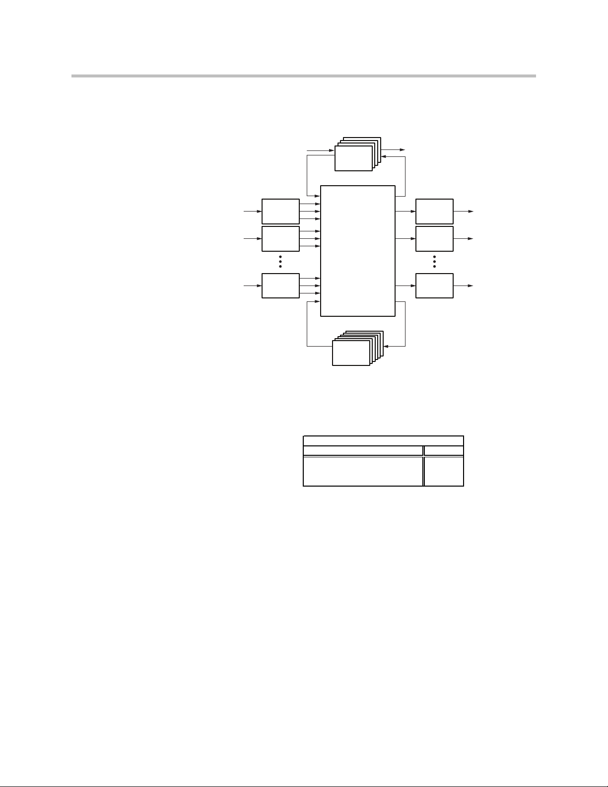
The SoundStructure processing includes input processing that is available on
all the inputs, output processing that is available on all the outputs, submix
processing that is available on all the submix signals, telephony processing
that is available on all the optional telephony interfaces, and an audio matrix
that connects this processing together. The high-level architecture is shown in
2 - 1
Page 16
Design Guide for the Polycom SoundStructure C16, C12, C8, and SR12
1
2
N
1
2
N
Telco
Processing
Telco
Processing
Telco
Processing
Telco
Processing
Matrix
Processing
SubMix
Submix
Processsing
Output
Processing
Output
Processing
Output
Processing
Input
Processing
Input
Processing
Input
Processing
# inputs 16 12 8 12
# outputs 16 12 8 12
# submixes 16 12 8 12
SoundStructure
the following figure for a SoundStructure device that has N inputs and N
outputs. The specific input and output processing will depend on the product
family (C-series or SR-series) and is described later in this chapter.
The table following summarizes the numbers of inputs, outputs, and the
number of submixes supported within each type of device. As shown in this
table, each SoundStructure device has as many submixes as there are inputs to
the device.
C16 C12 C8 SR12
A summary of the different types of processing in the C-series and SR-series
products is shown in the following table. As can be seen in this table, the
difference between the products is that the C-series products include acoustic
2 - 2
Page 17

C-Series SR-Series
Input Processing
Up to 8th order highpass and lowpass
99
1st or 2nd order high shelf and low shelf
99
10-band parametric equalization
99
Acoustic echo cancellation, 20-22kHz 200 msec tail-time, monaural or stereo
9
Automatic gain control: +15 to -15dB
99
Dynamics processing: gate, expander, compressor, limiter, peak limiter
99
Feedback Eliminator: 10 adaptive f ilters
99
Noise cancellation: 0-20dB noise reduction
99
Automixer: gain sharing or gated mixer
99
Signal fader gain: +20 to -100 dB
99
Signal delay to 1000 msec
99
Output Processing
1st or 2nd order high shelf and low shelf filters
99
10-bands of parametric or 31-band graphic equalizer
99
Dynamics processing: gate, expander, compressor, limiter, peak limiter
99
Signal fader gain: +20 to -100 dB
99
Signal delay: up to 1000 msec
99
Submix Processing
Up to 8th order highpass and lowpass filters
99
1st or 2nd order high shelf and low shelf filters
99
10-bands of parametric equalization
99
Dynamics processing: gate, expander, compressor, limiter, peak limiter
99
Signal fader gain: +20 to -100 dB
99
Signal delay: up to 1000 msec
99
Telco Processing
Line echo cancellation, 80-3300Hz, 32msec tail-time
99
Dynamics processing: gate, expander, compressor, limiter, peak limiter on telco transmit and receive
99
Up to 8th order highpass and lowpass filters
99
1st or 2nd order high shelf and low shelf filters
99
10-bands of parametric equalization on telco transmit and receive
99
Call progress detection
99
Signal fader gain: +20 to -100 dB
99
Automatic gain control: +15 to -15dB on telco receive
99
Signal delay on telco transmit and receive: up to 1000 msec
99
Noise cancellation: 0-20dB noise reduction on telco receive
99
SoundStructure
SoundStructure Product Family
echo cancellation while the SR-series products do not include acoustic echo
cancellation. The processing capabilities will be described in the following
sections.
OBAM™ - One Big Audio Matrix
One of the significant advancements in the SoundStructure products is the
ability for multiple devices to be linked together and to be configured and
operated as one large system rather than as multiple individual devices
feature dramatically simplifies any installation where audio from more than
one device is required such as complicated sound reinforcement applications.
OBAM's 'one large system' approach provides many benefits including:
1
Requires SoundStructure firmware release 1.2 or higher.
1
. This
2 - 3
Page 18
Design Guide for the Polycom SoundStructure C16, C12, C8, and SR12
OBAM
OUTIN
OUTIN
OUTIN
OBAM
36x16
16x16 12x12 8x8
36x12 36x8
36x36
• It is easier to work with the system because all the input signals feed into
the single matrix and all the outputs are fed from the single matrix
• The a/v designer can be more creative as there are no limitations on how
signals from multiple devices can be used together
• The device linking scheme is completely transparent to the designer - all
input signals are shared to all devices dramatically simplifying the setup,
configuration and maintenance of large systems
• It is easier to set up the system with SoundStructure Studio as all inputs
and outputs are viewed on one screen, eliminating the need to configure
multiple devices and view multiple pages
This one big system design approach is the result of the SoundStructure
architectural design and the OBAM high-speed bi-directional link interface
between devices. With OBAM linking, up to eight devices may be linked
together. If there are plug-in cards installed in multiple linked SoundStructure
devices, the plug-in card resources are available for routing to any output
across the system. See the Hardware Installation Guide or Chapter 3 for more
information on how to link multiple devices together.
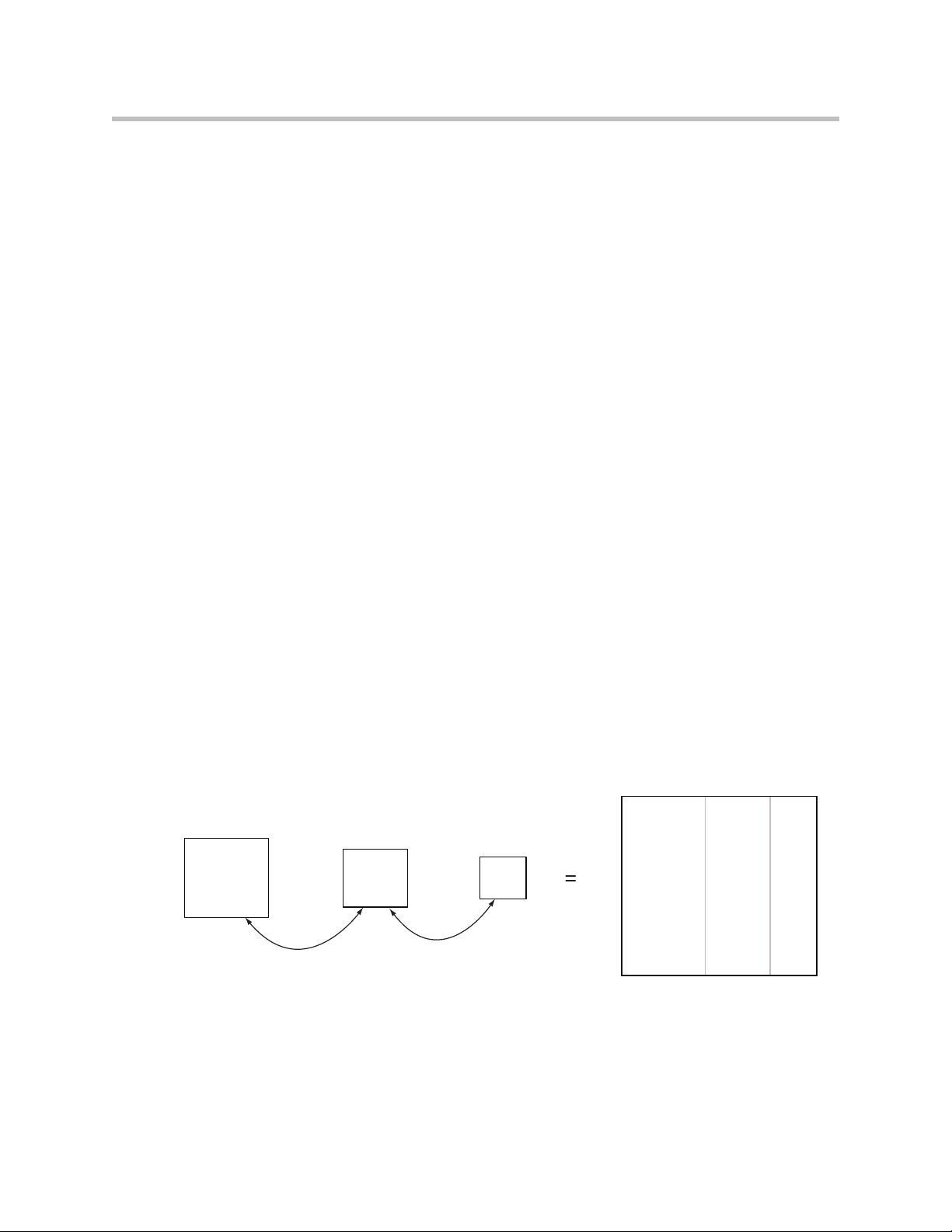
The one large system design philosophy means that the audio matrix of a
system of SoundStructure devices is the size of the total number of inputs and
outputs of all the component devices that are linked together. Since one
SoundStructure C16 device has a 16x16 matrix, two C16 devices linked
together create a 32x32 matrix and so forth.
The one big audio matrix architecture can be seen in the following figure
where a C16 device is OBAM linked to a C12 device which is OBAM linked to
a C8 device. The resulting system will have 36x36 inputs and 36 outputs
(16+12+8 = 36). In addition to all the inputs and outputs, the submixes of each
device will also feed the matrix allowing the designer to have 36 submix
signals (not shown in the following figure), one for each input that can be used
in the system.
Because of the OBAM design architecture, the A/V designer no longer has to
be concerned with device linking, as multiple SoundStructure devices will
behave as, and be configured as, one large system.
2 - 4
Page 19
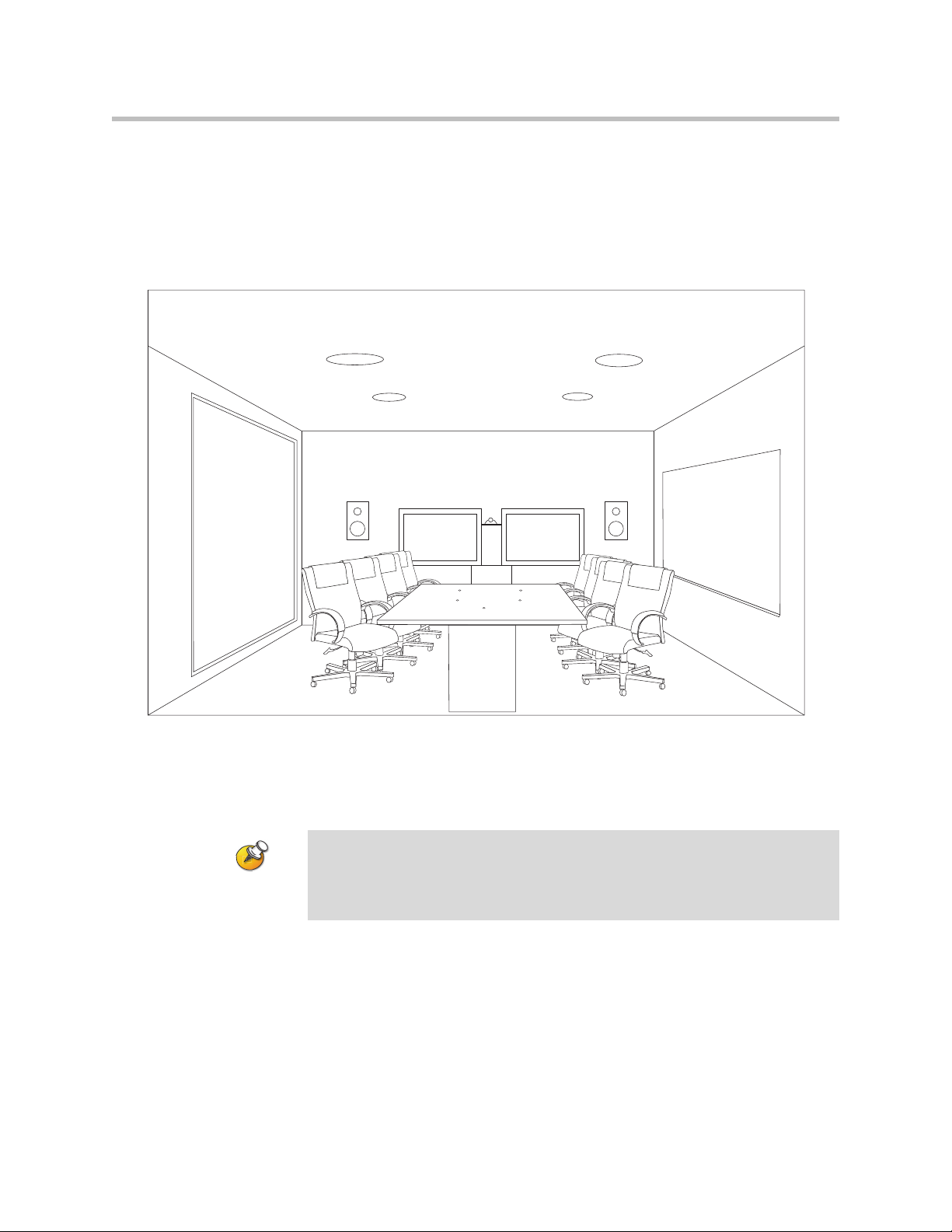
SoundStructure C-series Products
The SoundStructure C16, C12, and C8 devices are designed for audio
conferencing applications where groups of people want to communicate to
other individuals or groups such as in a typical room shown in the following
figure.
SoundStructure Product Family
The SoundStructure C-series products feature both monaural and stereo
acoustic echo cancellation, noise cancellation, equalization, dynamics
processing, feedback elimination, automatic microphone mixing, and more.
All audio inputs have the same processing capability and can be used with either
microphone-level or line-level inputs. Phantom power is available on all inputs.
All outputs have the same processing capability.
A single SoundStructure C16, C12, or C8 device supports 16, 12, or 8
microphone or line inputs and 16, 12, or 8 line outputs, respectively. Up to
eight SoundStructure devices may be linked together (any combination of
SoundStructure C-series or SR-series products may be used together) to build
audio processing systems that support up to one hundred twenty-eight analog
inputs and analog outputs.
2 - 5
Page 20
Design Guide for the Polycom SoundStructure C16, C12, C8, and SR12
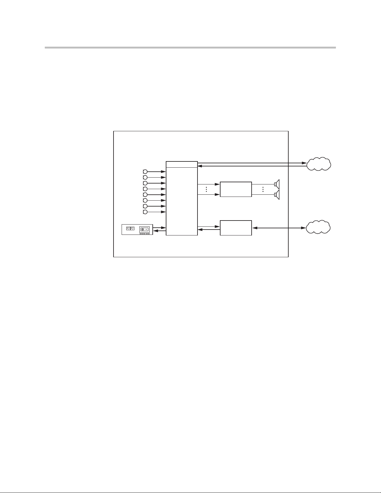
Telco
Video Codec
Amplifier
SoundStructure
C16
Microphones
Telephony
Playback/Record
Network
PSTN
Network
Favorite Content
SoundStructure Installation
Each SoundStructure C-series device may be used with traditional analog
microphones, with Polycom's HDX digital microphone arrays
1
. For detailed
information on using the Polycom HDX digital microphone arrays, see
Chapter 6.
Typical applications of the SoundStructure C-series conferencing products are
audio and video conferencing where two or more remote locations are
conferenced together. The typical connections in the room are shown in the
following figure.
2 - 6
Before designing with SoundStructure products, the details of the
SoundStructure signal processing capabilities will be presented.
1
Requires SoundStructure firmware release 1.1 or higher.
Page 21
C-Series Input Processing
10-band parametric equalization
Acoustic echo cancellation, 20-22kHz 200 msec tail-time, monaural or stereo
Automatic gain control: +15 to -15dB
Dynamics processing: gate, expander, compressor, limiter, peak limiter
Signal fader gain: +20 to -100 dB
Signal delay to 1000 msec
Mic or Line
Input
Input to
Matrix
Input to
Matrix
Parametric
Equalization
A/D
Converter
Analog
Gain
Acoustic Echo
Cancellation
Noise
Cancellation
Automatic
Gain Control
Automixer
AGC Dynamics Fader Delay
Fader
Automixer
Automixer
Delay
Automatic
Gain Control
Non Linear
Processing
Feedback
Cancellation
Dynamics
Processor
Dynamics
Processor
Fader
Input to
Matrix
Automatic
Gain Control
Fader Delay
Dynamics
Processor
Delay
Mute
Router
Recording/
Ungated
Conferencing
Sound
Reinforcement
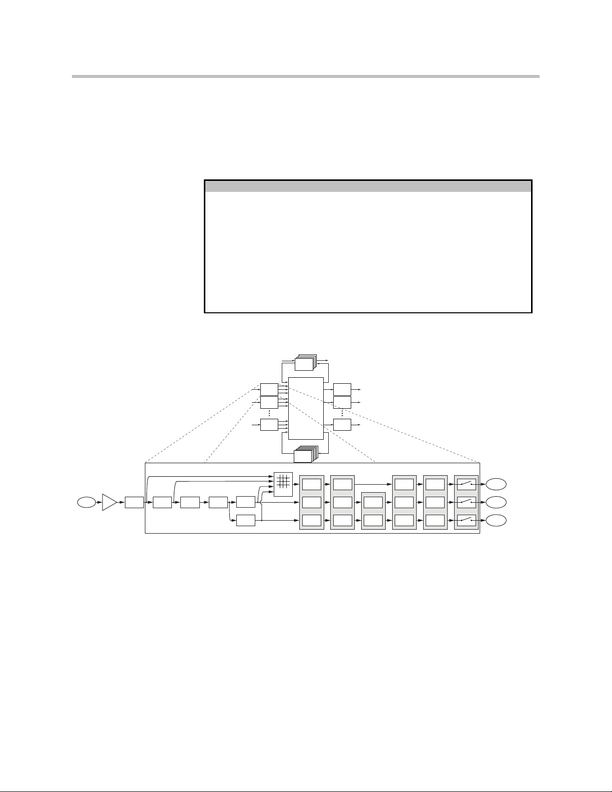
The input processing on the SoundStructure C-series devices is designed to
make it easy to create conferencing solutions either with or without sound
reinforcement. Each audio input on a SoundStructure C-series device has the
processing shown in the following table.
Input Processing
Up to 8th order highpass and lowpass
1st or 2nd order high shelf and low shelf
Feedback Eliminator: 10 adaptive filters
Noise cancellation: 0-20dB noise reduction
Automixer: gain sharing or gated mixer
The signal processing follows the signal flow shown in the following figure.
SoundStructure Product Family
Telco
Telco
Telco
Processing
Telco
Processing
Processing
Processing
Input
1
Processing
Input
2
Processing
Input
N
Processing
Matrix
SubMix
Submix
Processing
Processsing
Output
Processing
Output
Processing
Output
Processing
1
2
N
Each analog input signal has an analog gain stage that is used to adjust the gain
of the input signal to the SoundStructure's nominal signal level of 0 dBu. The
analog gain stage can provide from -20 to 64 dB of gain in 0.5 dB steps. There
is also an option to enable 48 V phantom power on each input. Finally the
2 - 7
Page 22
Design Guide for the Polycom SoundStructure C16, C12, C8, and SR12
Mic or Line
Input
Parametric
Equalization
A/D
Converter
Analog
Gain
Acoustic Echo
Cancellation
Noise
Cancellation
Non Linear
Processing
Feedback
Cancellation
Route
C-Series Input Processing
Input to
Matrix
Input to
Matrix
Automatic
Gain Control
Automixer
AGC Dynamics Fader Delay
Fader
Automixer
Automixer
Delay
Automatic
Gain Control
Dynamics
Processor
Dynamics
Processor
Fader
Input to
Matrix
Automatic
Gain Control
Fader Delay
Dynamics
Processor
Delay
Mute
Router
Recording/
Ungated
Conferencing
Sound
Reinforcement
analog input signal is digitized and available for processing. The digital signal
is processed by five different DSP algorithms: parametric equalization,
acoustic echo cancellation, noise cancellation, feedback reduction, and echo
suppression (non linear processing).
C-Series Input Processing
A/D
Parametric
Mic or Line
Analog
Input
Gain
Acoustic Echo
Converter
Equalization
Cancellation
Non Linear
Noise
Processing
Cancellation
Feedback
Cancellation
AGC Dynamics Fader Delay
Automatic
Dynamics
Gain Control
Router
Processor
Dynamics
Automatic
Processor
Gain Control
Automatic
Dynamics
Gain Control
Processor
Fader Delay
Automixer
Fader
Automixer
Fader
Automixer
Mute
Recording/
Input to
Matrix
Ungated
Delay
Delay
Input to
Conferencing
Matrix
Sound
Input to
Matrix
Reinforcement
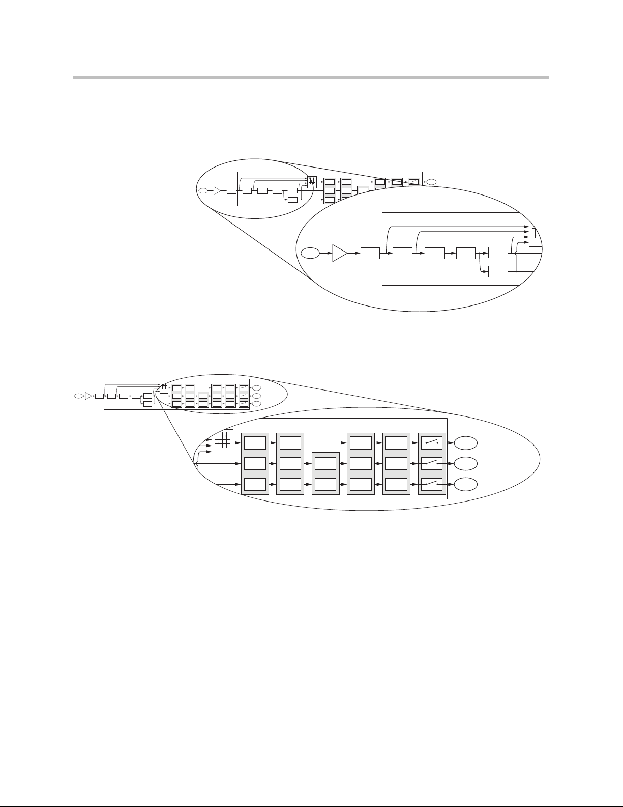
Continuing through the signal path as shown in the next figure, the input
signal continues through the AGC (automatic gain control), dynamics
processing, an automixer, an audio fader, and finally through the input delay.
AGC Dynamics Fader Delay
Automatic
Dynamics
Gain Control
Processor
Router
A/D
Mic or Line
Input
Parametric
Analog
Converter
Equalization
Gain
Non Linear
Acoustic Echo
Noise
Processing
Cancellation
Cancellation
Feedback
Cancellation
Automixer
Dynamics
Automatic
Automixer
Processor
Gain Control
Automatic
Dynamics
Automixer
Gain Control
Processor
Fader Delay
Fader
Fader
Mute
Input to
Recording/
Matrix
Ungated
Input to
Delay
Delay
Conferencing
Matrix
Sound
Input to
Matrix
Reinforcement
2 - 8
Each analog input signal is processed to generate three different versions of
the processed input signal that can be used simultaneously in the matrix:
1. Conferencing version,
2. Sound reinforcement version, and
3. Recording/ungated version
The AGC, dynamics processor, and input fader are linked together on all three
audio paths and apply the same gain to the signal paths based on an analysis
of the signal earlier in the signal path.
The automixer processing is only applied to the conferencing and sound
reinforcement signal paths to ensure that there is an 'un'-automixed version of
the input signal available for recording/ungated applications.
Page 23
SoundStructure Product Family
Mic or Line
Input
Input to
Matrix
Input to
Matrix
Parametric
Equalization
A/D
Converter
Analog
Gain
Acoustic Echo
Cancellation
Noise
Cancellation
Automatic
Gain Control
Automixer
AGC Dynamics Fader Delay
Fader
Automixer
Automixer
Delay
Automatic
Gain Control
Non Linear
Processing
Feedback
Cancellation
Dynamics
Processor
Dynamics
Processor
Fader
Input to
Matrix
Automatic
Gain Control
Fader Delay
Dynamics
Processor
Delay
Mute
Router
Recording/
Ungated
Conferencing
Sound
Reinforcement
C-Series Conferencing Input Processing
Parametric
Equalization
Acoustic Echo
Cancellation
Noise
Cancellation
Automatic
Gain Control
Fader
Automixer
Delay
Non Linear
Processing
Dynamics
Processor
Mute
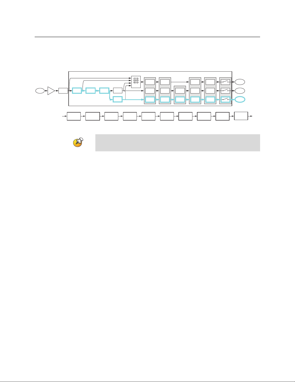
Each analog input signal is processed to create three processed versions that can
be used in different ways in the matrix.
These three different versions of the input signal mean that, at the same time,
an output signal to the loudspeakers can use the sound reinforcement
processed version of an input signal, an output signal to the video
conferencing system can use the conferencing processed version of the input
signal, and an output signal to the recording system can use the recording
processed version of the input signal. The decision of which of these three
processed version is used is made at each matrix crosspoint on the matrix as
described in the Matrix Crosspoint section below.
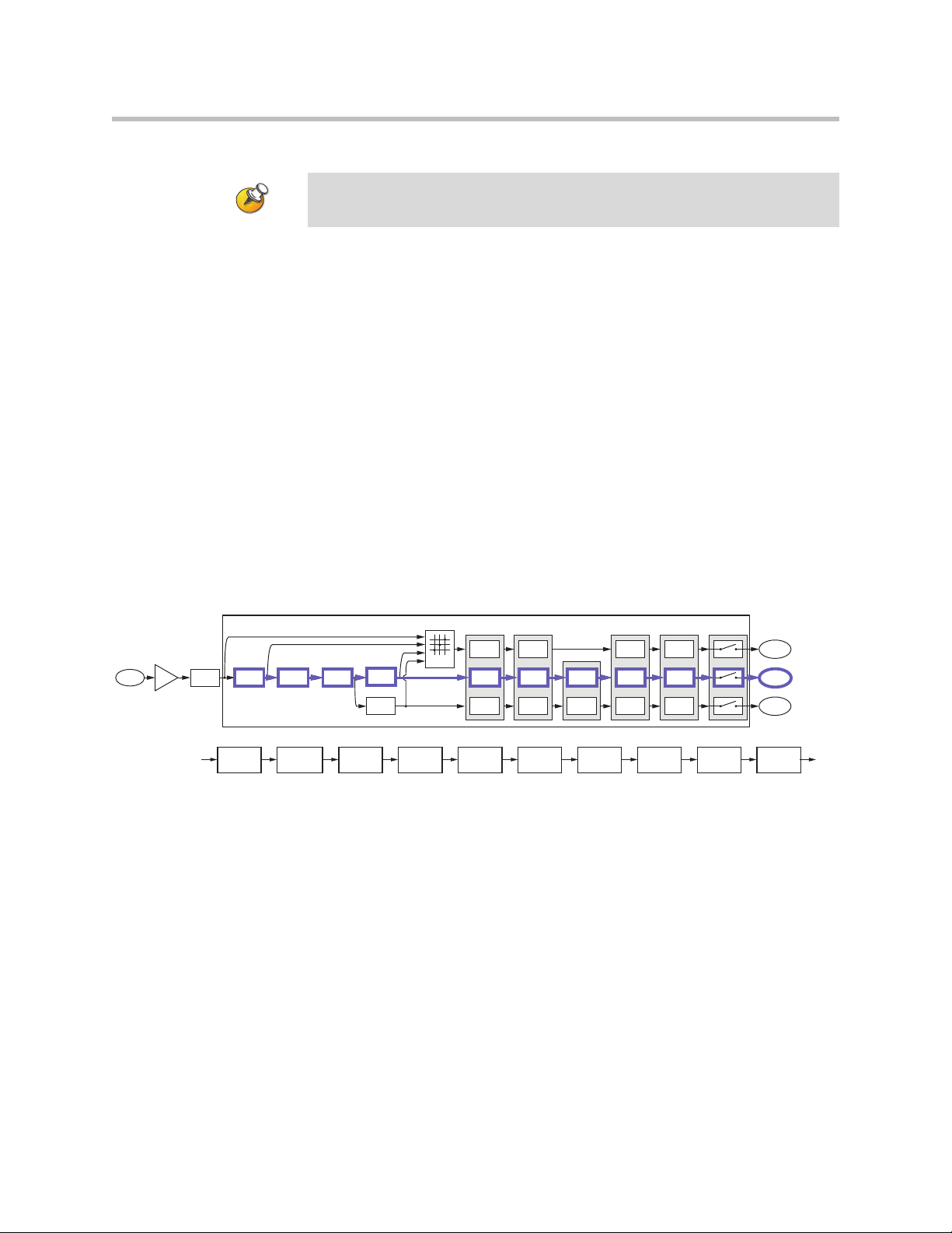
Conferencing Version
The conferencing version will be processed with the acoustic echo and noise
cancellation settings, non-linear signal processing, automatic gain control,
dynamics processing, automixer, fader, delay, and input mute. The
conferencing signal path and summary block diagram is highlighted in the
following figure. This is the path that is typically used to send echo and noise
cancelled microphone audio to remote locations. This is the default processing
for microphone inputs when the automixed version of the signal is selected.
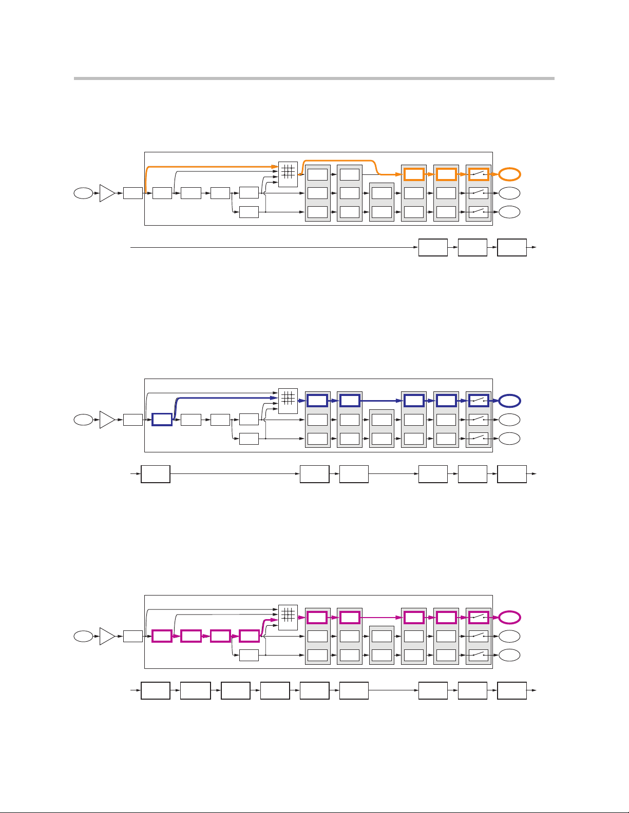
Sound Reinforcement Version
The sound reinforcement version will be processed with the echo and noise
cancellation, optional feedback elimination processing, automatic gain
control, dynamics processing, automixer, fader, delay, and input mute. This is
the path that is typically used for sending local audio to loudspeakers in the
room for sound reinforcement. There is no non-linear processing on this path
so that the local talker audio to the loudspeakers is not affected by the presence
of remote talker audio in the local room.
The automatic gain control on the sound reinforcement path is different from
the automatic gain control on the conferencing version of the signal because
the sound reinforcement automatic gain control will not add gain to the signal.
In other words, the sound reinforcement AGC will only reduce the gain of the
input signal. This restriction on the sound reinforcement AGC is to prevent the
2 - 9
Page 24
Design Guide for the Polycom SoundStructure C16, C12, C8, and SR12
Mic or Line
Input
Input to
Matrix
Input to
Matrix
Parametric
Equalization
A/D
Converter
Analog
Gain
Acoustic Echo
Cancellation
Noise
Cancellation
Automatic
Gain Control
Automixer
AGC Dynamics Fader Delay
Fader
Automixer
Automixer
Delay
Automatic
Gain Control
Non Linear
Processing
Feedback
Cancellation
Dynamics
Processor
Dynamics
Processor
Fader
Input to
Matrix
Automatic
Gain Control
Fader Delay
Dynamics
Processor
Delay
Mute
Router
Recording/
Ungated
Conferencing
Sound
Reinforcement
C-Series Sound Reinforcement Input Processing
Parametric
Equalization
Acoustic Echo
Cancellation
Noise
Cancellation
Automatic
Gain Control
Fader
Automixer
Delay
Feedback
Cancellation
Dynamics
Processor
Mute
automatic gain control on the sound reinforcement path from increasing the
microphone gain and consequently reducing the potential acoustic gain before
the onset of feedback.
The automatic gain control on the sound reinforcement processing path will not add
gain to the signal, it will only reduce the gain of the signal.
Recording/Ungated Version
The recording version of the processed input signal is specifically designed to
not include the gain sharing or gated style of automatic microphone mixing
processing. The recording/ungated version of the input channel is typically
used for recording applications or in any application where an un-automixed
version of the input signal is required.
For additional flexibility in audio applications, there are four different
versions of the recording/ungated signal that can be selected through the
four-input router shown in the above processing figures. This selection of
which type of recording/ungated signal to choose is performed on an input by
input basis within the SoundStructure Studio software as described in Chapter
5.
The four ungated versions are described in more detail below:
1. bypass version
2. line input version
3. conferencing version
4. sound reinforcement version
Recording/Ungated - Bypass
The recording/ungated-bypass version has no input processing other than a
fader gain control, input delay, and input mute. This version bypasses the
automatic gain control and dynamics processing as shown in the following
figure. This version can be used when it is important to minimal audio
2 - 10
Page 25
SoundStructure Product Family
Mic or Line
Input
Input to
Matrix
Input to
Matrix
Parametric
Equalization
A/D
Converter
Analog
Gain
Acoustic Echo
Cancellation
Noise
Cancellation
Automatic
Gain Control
Automixer
AGC Dynamics Fader Delay
Fader
Automixer
Automixer
Delay
Automatic
Gain Control
Non Linear
Processing
Feedback
Cancellation
Dynamics
Processor
Dynamics
Processor
Fader
Input to
Matrix
Automatic
Gain Control
Fader Delay
Dynamics
Processor
Delay
Mute
Router
Recording/
Ungated
Conferencing
Sound
Reinforcement
UNGATED - Bypass
Fader Delay
Mute
Mic or Line
Input
Input to
Matrix
Input to
Matrix
Parametric
Equalization
A/D
Converter
Analog
Gain
Acoustic Echo
Cancellation
Noise
Cancellation
Automatic
Gain Control
Automixer
AGC Dynamics Fader Delay
Fader
Automixer
Automixer
Delay
Automatic
Gain Control
Non Linear
Processing
Feedback
Cancellation
Dynamics
Processor
Dynamics
Processor
Fader
Input to
Matrix
Automatic
Gain Control
Fader Delay
Dynamics
Processor
Delay
Mute
Router
Recording/
Ungated
Conferencing
Sound
Reinforcement
UNGATED - Line Input Processing
Parametric
Equalization
Automatic
Gain Control
Fader Delay
Dynamics
Processor
Mute
Mic or Line
Input
Input to
Matrix
Input to
Matrix
Parametric
Equalization
A/D
Converter
Analog
Gain
Acoustic Echo
Cancellation
Noise
Cancellation
Automatic
Gain Control
Automixer
AGC Dynamics Fader Delay
Fader
Automixer
Automixer
Delay
Automatic
Gain Control
Non Linear
Processing
Feedback
Cancellation
Dynamics
Processor
Dynamics
Processor
Fader
Input to
Matrix
Automatic
Gain Control
Fader Delay
Dynamics
Processor
Delay
Mute
Router
Recording/
Ungated
Conferencing
Sound
Reinforcement
UNGATED - Conferencing Processing
Parametric
Equalization
Acoustic Echo
Cancellation
Noise
Cancellation
Automatic
Gain Control
Fader Delay
Non Linear
Processing
Dynamics
Processor
Mute
processing on an input signal. This version of the signal has no acoustic echo
cancellation processing and will consequently include any acoustic echo signal
that may be present at the microphones.
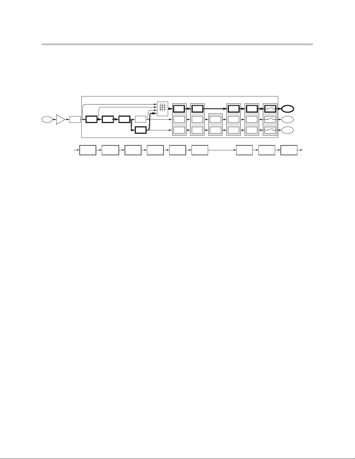
Recording/Ungated - Line Input
The recording - line input version includes equalization, automatic gain
control, and the dynamics processing as well as fader gain control, input delay,
and input mute as shown in the following figure. This processing path is
typically used by line input signals such as program audio, and hence the
name line input path.
Recording/Ungated - Conferencing
The ungated conferencing processed input includes the acoustic echo and
noise cancellation as shown in the following figure. This path is typically used
for recording of conference microphones as it includes all the acoustic echo
cancellation but not the automatic microphone mixer processing.
2 - 11
Page 26
Design Guide for the Polycom SoundStructure C16, C12, C8, and SR12
Mic or Line
Input
Input to
Matrix
Input to
Matrix
Parametric
Equalization
A/D
Converter
Analog
Gain
Acoustic Echo
Cancellation
Noise
Cancellation
Automatic
Gain Control
Automixer
AGC Dynamics Fader Delay
Fader
Automixer
Automixer
Delay
Automatic
Gain Control
Non Linear
Processing
Feedback
Cancellation
Dynamics
Processor
Dynamics
Processor
Fader
Input to
Matrix
Automatic
Gain Control
Fader Delay
Dynamics
Processor
Delay
Mute
Router
Recording/
Ungated
Conferencing
Sound
Reinforcement
UNGATED - Sound Reinforcement Processing
Parametric
Equalization
Acoustic Echo
Cancellation
Noise
Cancellation
Automatic
Gain Control
Fader Delay
Feedback
Cancellation
Dynamics
Processor
Mute
Recording/Ungated - Sound Reinforcement
Finally, the sound reinforcement recording input includes the echo and noise
cancellation and optional feedback elimination processing as shown in the
following figure.
All three versions (conferencing, sound reinforcement, recording/ungated) of
the input signal processing can be used simultaneously in the matrix. The
conferencing version is typically used to send to remote participants, the
sound reinforcement version is typically used to send to the local loudspeaker
system, and the recording version is typically used for archiving the
conference audio content.
C-Series Matrix Crosspoints
The audio matrix is used to create different mixes of input signals and submix
signals to be sent to output signals and submix signals. Matrix crosspoints gain
values are shown in dB where 0 dB means a signal value is unchanged. For
example, a crosspoint value of -6 dB will lower the signal gain by 6 dB before
it is summed with other signals. The matrix crosspoint gain can be adjusted in
0.1 dB steps between -100 and +20 dB and may also be completely muted. In
addition, the matrix crosspoint can also be negated/inverted so that the
crosspoint arithmetic creates a subtraction rather than an addition. The
inversion technique may be effective in difficult room reinforcement
environments by creating phase differences in alternating zones to add more
gain before feedback.
Matrix crosspoints associated with stereo channels have a balance or pan to
control mapping mono to stereo channels, stereo to mono channels, and stereo
to stereo channels.
The three different versions of the input processing - the ungated,
conferencing, and sound reinforcement - are selected at the matrix crosspoint.
The SoundStructure Studio software allows the user to select which version of
the input signal processing at the matrix crosspoint. As will be shown in
Chapter 4 Creating Designs, the different versions of the input processing will
be represented with different background colors in the matrix crosspoint.
2 - 12
Page 27
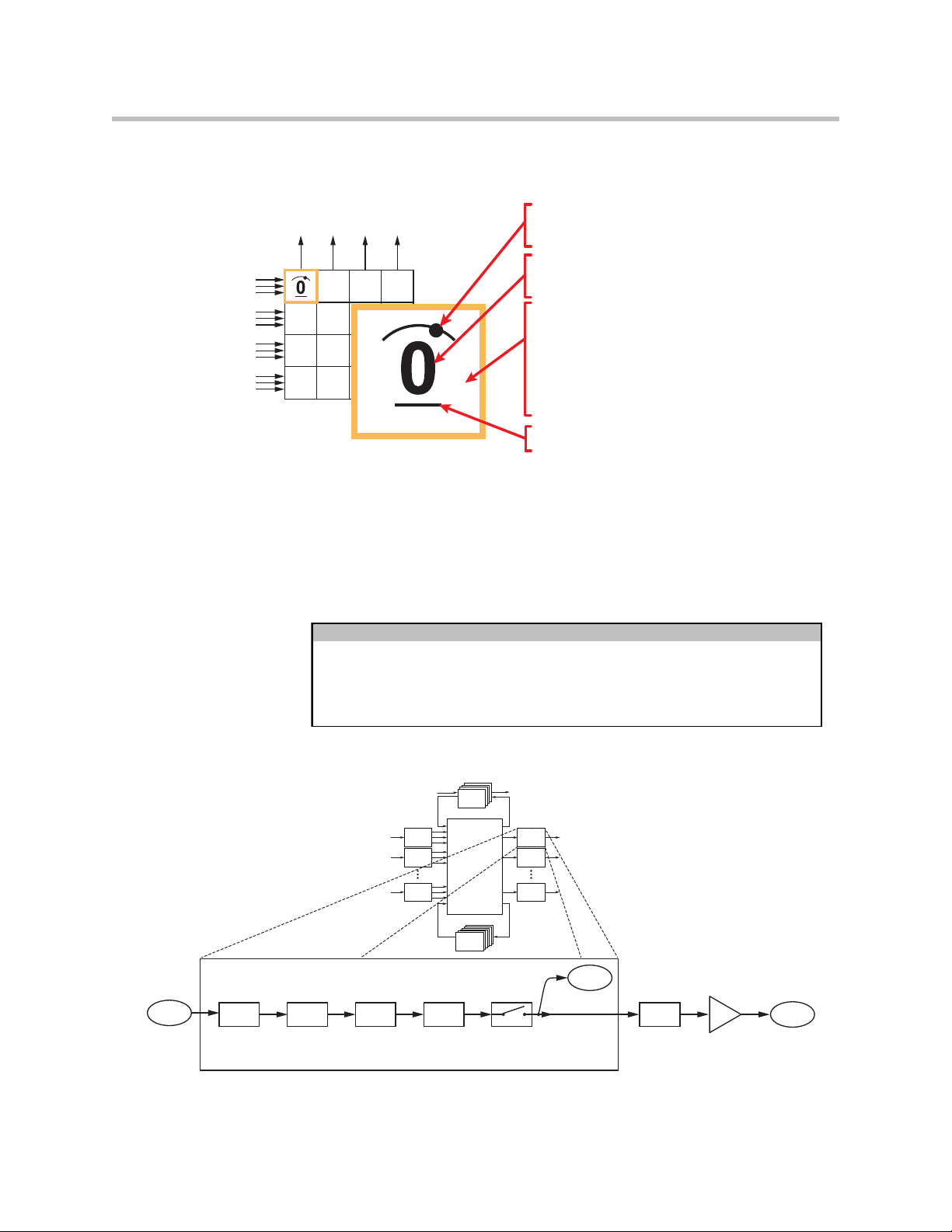
The following figure highlights how to interpret the matrix crosspoints in the
Outputs
Ungated/Recording
Conferencing
Sound Reinforcement
Ungated/Recording
Conferencing
Sound Reinforcement
Ungated/Recording
Conferencing
Sound Reinforcement
Ungated/Recording
Conferencing
Sound Reinforcement
Inputs
Crosspoint background indicates
version of input processing
White - Ungated/Recording
Blue - Conferencing (C-series),
Noise cancelled (SR-series)
Light Blue - Sound Reinforcement
Value of crosspoint is the gain in dB
Arc indicates L/R balance or pan
No arc indicates centered balance/pan
Underscore indicates Inverted polarity
Bold text Indicates signal is unmuted
1st or 2nd order high shelf and low shelf filters
10-bands of parametric or 31-band graphic equalizer
Signal fader gain: +20 to -100 dB
Signal delay: up to 1000 msec
matrix.
C-Series Output processing
As shown in the following table and figure, each output signal from the matrix
can be processed with dynamics processing, either 10-band parametric or 10-,
15-, or 31-band graphic equalization, a fader, and output delay up to 1000
milliseconds.
Output Processing
SoundStructure Product Family
Output Processing
Output from
Matrix
Dynamics
Processing
Parametric
or Graphic
Equalization
Dynamics processing: gate, expander, compressor, limiter, peak limiter
Telco
Telco
Telco
Processing
Telco
Processing
Processing
Processing
Input
1
Processing
Input
2
Processing
Input
N
Processing
Fader Delay
Matrix
SubMix
Submix
Processing
Processsing
Mute
Output
Processing
Output
Processing
Output
Processing
1
2
N
AEC
Reference
D/A
Converter
Analog
Gain
Output
Signal
2 - 13
Page 28
Design Guide for the Polycom SoundStructure C16, C12, C8, and SR12
Submix
Processing
Matrix
Output
SubMix
Signal
Matrix
Input
1st or 2nd order high shelf and low shelf filters
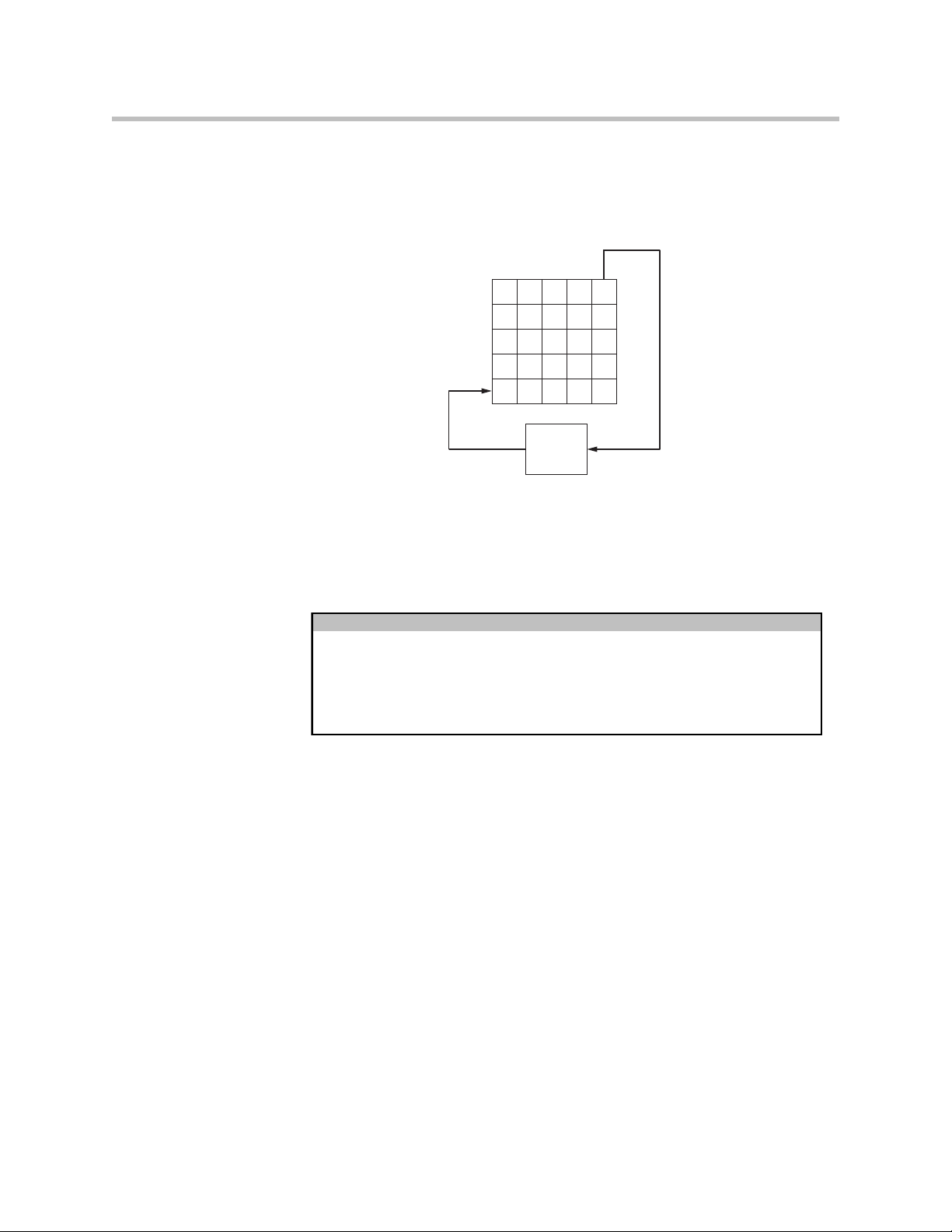
10-bands of parametric equalization
C-Series Submix Processing
Submixes are outputs from the matrix that can be routed directly back to the
input of the matrix as shown in the following figure.
As an output of the matrix, any combination of input signals may be mixed
together to create the output submix signal. This output signal can be
processed with the submix processing and the processed signal will be
available as an input to the matrix. Typically microphone, remote audio
sources, or other signals will be sent to a submix channel and the resulting
submix signal used as a single input in the matrix.
Submix Processing
Up to 8th order highpass and lowpass filters
Dynamics processing: gate, expander, compressor, limiter, peak limiter
Signal fader gain: +20 to -100 dB
Signal delay: up to 1000 msec
2 - 14
Page 29
SoundStructure Product Family
AEC
r
AmpA
AEC reference for remote roomAEC reference for local room
As shown in the following figure, each submix signal from the matrix can be
processed with dynamics processing, parametric equalization, a fader, and up
to 1000 milliseconds of delay. Each SoundStructure device has as many
submixes as there are inputs.
Telco
Telco
Telco
Processing
Telco
Processing
Processing
Processing
1
2
N
Input
Processing
Input
Processing
Input
Processing
Submix Processing
Submix Input
from Matrix
Dynamics
Processing
Parametric
Equalization
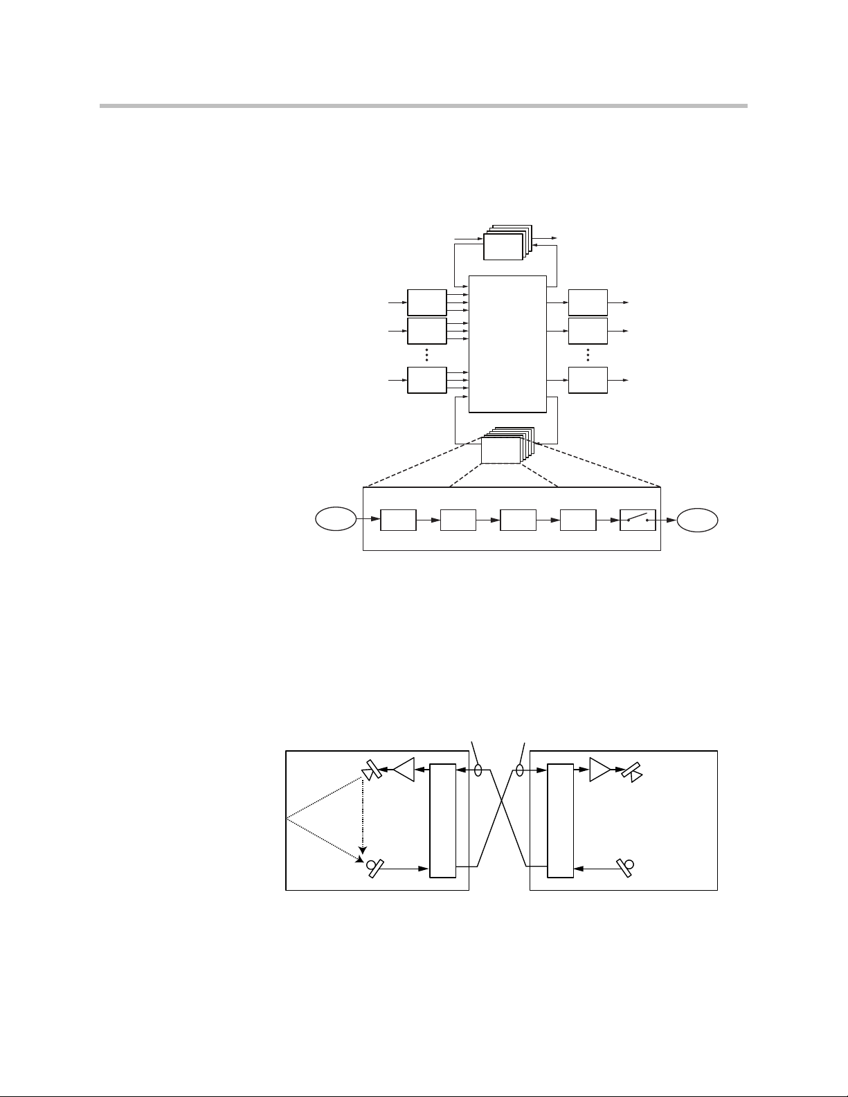
C-Series Acoustic Echo Canceller References
In conferencing applications, an acoustic echo canceller removes the remote
site's audio that is played in the local room from being picked up by the local
microphones and sent back to the remote participants. The AEC
following figure removes the acoustic echo of the remote talker so it is not sent
back to the remote talker.
Matrix
SubMix
Submix
Processing
Processsing
Fader Delay
Output
Processing
Output
Processing
Output
Processing
Mute
1
2
N
Submix output
to Matrix
Local Room
in the
Local Room
LocalTalke
Local Room
mp
Remote Room
AEC
Remote Room
Remote Talker
Acoustic echo cancellation processing is only required on the inputs that have
microphone audio connected that will “hear” both the local talkers’ speech
and the acoustic echo of the remote talkers’ speech.
2 - 15
Page 30

Design Guide for the Polycom SoundStructure C16, C12, C8, and SR12
In order for the local acoustic echo canceller to cancel the acoustic echo of the
remote participants, it must have an echo canceller reference defined. The echo
canceller reference includes all the signals from the remote site that should be
echo cancelled. In the following figure, the AEC reference for both the local
and remote rooms includes the audio that is played out the loudspeaker. See
Appendix B - Designing Audio Conferencing Systems for additional
information on audio conferencing systems and acoustic echo cancellation.
Within SoundStructure devices, the acoustic echo canceller on each input can
have either one or two AEC references specified per input signal. For
traditional monaural audio or video conferencing applications, only one
acoustic echo canceller reference is used and that would typically be the signal
that is sent to the single loudspeaker zone. See the “8 microphones, video, and
telephony application” in Chapter 9 for an example.
Applications that have two independent audio sources played into the room
such as stereo audio from a stereo video codec require two mono AEC
references, or one stereo AEC reference. See the 8 microphones and stereo
video conferencing application in Chapter 9.
An acoustic echo canceller reference can be created from any output signal or
any submix signal. For a SoundStructure C16 device this means that there are
32 possible echo canceller references (16 outputs + 16 submixes) that can be
defined and selected.
SoundStructure SR-Series Products
The SoundStructure SR12 has a similar architecture to the SoundStructure
C-series. While the SoundStructure SR12 does not include acoustic echo
cancellation processing it does include noise cancellation, automatic
microphone mixing, matrix mixing, equalization, feedback elimination,
dynamics processing, delay, and submix processing. The “SR” in the name
stands for 'sound reinforcement'.
The SoundStructure SR12 is designed for both the non-conferencing
applications where local audio is played into the local room or distributed
throughout a facility and for conferencing applications to provide additional
line input and output signals when linked to a C-series product. Applications
for the SoundStructure SR12 include live sound, presentation audio, sound
2 - 16
Page 31

SoundStructure Product Family
Telco
Video Codec
Amplifier
SoundStructure
C8
SoundStructure
SR12
Microphones
Telephony
Loudspeakers
Video
Local
Audio
Playback
Network
PSTN
Network
Playback/Record
Favorite Content
Playback/Record
Favorite Content
Amplifier
Loudspeakers
Local
Audio
Playback
SR-Series
12:00 am
VHS
reinforcement, and broadcasting. The following figure shows an example of
using the SoundStructure SR12 to provide additional line level inputs and
outputs to a SoundStructure C8 conferencing product.
The SoundStructure SR12 can not be used to add additional conferencing
microphones to a C series product because there is no acoustic echo
cancellation processing on the SoundStructure SR12 inputs. The following
figure shows an installation that would not work because the microphones
that are connected to the SoundStructure SR12 would not be echo cancelled. If
more conferencing microphones are required than can be used with a
2 - 17
Page 32

Design Guide for the Polycom SoundStructure C16, C12, C8, and SR12
Telco
Video Codec
Amplifier
SoundStructure
C8
SoundStructure
SR12
Microphones
Telephony
Loudspeakers
Video
Local
Audio
Playback
Network
PSTN
Network
Amplifier
Loudspeakers
Local
Audio
Playback
SR-Series
particular SoundStructure C-series device, either the next largest C-series
device or additional C-series devices must be used to support the number of
microphones required.
2 - 18
The C-series and SR-series products can be used together and linked to form
larger systems that can support up to eight SoundStructure devices, one
hundred twenty-eight inputs, one hundred twenty-eight outputs, and eight
plug-in daughter cards.
For information on how to rack mount and terminate cables to the
SoundStructure devices, refer to the SoundStructure Hardware Installation
Guide.
Page 33

SR-Series Input Processing
10-band parametric equalization
Automatic gain control: +15 to -15dB
Dynamics processing: gate, expander, compressor, limiter, peak limiter
Feedback Eliminator: 10 adaptive filters
Mic or Line
Input
Input to
Matrix
Input to
Matrix
Parametric
Equalization
A/D
Converter
Analog
Gain
Noise
Cancellation
Automatic
Gain Control
Automixer
AGC Dynamics Fader Delay
Fader
Automixer
Automixer
Delay
Automatic
Gain Control
Feedback
Cancellation
Dynamics
Processor
Dynamics
Processor
Fader
Input to
Matrix
Automatic
Gain Control
Fader Delay
Dynamics
Processor
Delay
Mute
Router
Recording/
Ungated
Noise Cancelled
Sound
Reinforcement
The input processing on the SoundStructure SR-series devices is designed to
make it easy to create commercial sound and sound reinforcement solutions.
Each audio input on a SoundStructure SR-series device includes the signal
processing path shown in the following table.
SR-Series Input Processing
Up to 8th order highpass and lowpass
1st or 2nd order high shelf and low shelf
Noise cancellation: 0-20dB noise reduction
Automixer: gain sharing or gated mixer
Signal fader gain: +20 to -100 dB
Signal delay to 1000 msec
The processing for each input is shown in the following figure from analog
input signal to the three versions of input processing that lead to the matrix.
Telco
Telco
Processing
Telco
Processing
Processing
Processing
SoundStructure Product Family
Telco
Input
1
Processing
Input
2
Processing
Input
N
Processing
Matrix
SubMix
Submix
Processing
Processsing
Output
Processing
Output
Processing
Output
Processing
1
2
N
2 - 19
Page 34

Design Guide for the Polycom SoundStructure C16, C12, C8, and SR12
Mic or Line
Input
Parametric
Equalization
A/D
Converter
Analog
Gain
Noise
Cancellation
Feedback
Cancellation
SR-Series Input Processing
Rou
Each analog input signal has an analog gain stage that is used to adjust the gain
of the input signal to the SoundStructure's nominal signal level of 0 dBu. The
analog gain stage can provide from -20 to 64 dB of analog gain in 0.5 dB
increments. There is also an option to enable 48 V phantom power on each
input. Finally the analog input signal is digitized and ready for processing.
Mic or Line
SR-Series Input Processing
A/D
Parametric
Analog
Input
Converter
Gain
Equalization
Noise
Cancellation
Feedback
Cancellation
AGC Dynamics Fader Delay
Automatic
Dynamics
Gain Control
Automatic
Gain Control
Automatic
Gain Control
Processor
Dynamics
Processor
Dynamics
Processor
Router
Automixer
Automixer
Automixer
Fader Delay
Fader
Fader
Input to
Matrix
Input to
Delay
Matrix
Input to
Delay
Matrix
Continuing through the signal path as shown in the next figure, the input
signal processing continues through the AGC (automatic gain control),
dynamics processing, an automixer, an audio fader, and finally through the
input delay.
Each analog input signal will be processed to generate three different versions
of the processed input signal that can be used simultaneously in the matrix:
1. Noise cancelled version,
2. Sound reinforcement version, and
3. Recording/ungated version
The AGC, dynamics processor, and input fader are linked together on all three
audio paths and apply the same gain to the signal paths based on an analysis
of the signal earlier in the signal path.
2 - 20
Page 35

SoundStructure Product Family
Input to
Matrix
Input to
Matrix
Automatic
Gain Control
Automixer
AGC Dynamics Fader Delay
Fader
Automixer
Automixer
Delay
Automatic
Gain Control
Dynamics
Processor
Dynamics
Processor
Fader
Input to
Matrix
Automatic
Gain Control
Fader Delay
Dynamics
Processor
Delay
Mute
Router
Recording/
Ungated
Noise Cancelled
Sound
Reinforcement
The automixer processing is only applied to the noise cancelled and sound
reinforcement signal paths to ensure that there is an 'un'-automixed version of
the input signal available for recording/ungated applications
SR-Series Input Processing
A/D
Parametric
Mic or Line
Analog
Converter
Input
Gain
Noise
Equalization
Cancellation
Feedback
Cancellation
AGC Dynamics Fader Delay
Automatic
Dynamics
Gain Control
Router
Processor
Dynamics
Automatic
Processor
Gain Control
Automatic
Dynamics
Gain Control
Processor
Fader Delay
Automixer
Fader
Automixer
Automixer
Fader
Mute
Input to
Recording/
Matrix
Ungated
Delay
Delay
Input to
Noise Cancelled
Matrix
Sound
Input to
Matrix
Reinforcement
Each analog input signal is processed to create three processed versions that can
be used in different ways in the matrix.
These three different versions of the input signal mean that, at the same time,
an output signal to the loudspeakers can use the sound reinforcement
processed version of an input signal, another output signal can use the noise
cancelled version without feedback processing, and a different output signal
can use the recording version of the input signal. The decision of which of
these three processed versions to use is made at each matrix crosspoint as
described in the Matrix Crosspoint section following this section.
Noise Cancelled Version
The conferencing version is processed with input equalization, noise
cancellation, automatic gain control, dynamics processing, automixer, fader,
delay, and input mute. The noise cancelled signal path is highlighted in the
following figure and the block diagram of this processing is also shown. This
is the path that is typically used to send a noise reduced version of the
2 - 21
Page 36

Design Guide for the Polycom SoundStructure C16, C12, C8, and SR12
Mic or Line
Input
Input to
Matrix
Input to
Matrix
Parametric
Equalization
A/D
Converter
Analog
Gain
Noise
Cancellation
Automatic
Gain Control
Automixer
AGC Dynamics Fader Delay
Fader
Automixer
Automixer
Delay
Automatic
Gain Control
Feedback
Cancellation
Dynamics
Processor
Dynamics
Processor
Fader
Input to
Matrix
Automatic
Gain Control
Fader Delay
Dynamics
Processor
Delay
Mute
Router
Recording/
Ungated
Noise Cancelled
Sound
Reinforcement
SR-Series Noise Cancellation Input Processing
Parametric
Equalization
Noise
Cancellation
Automatic
Gain Control
Fader
Automixer
Delay
Dynamics
Processor
Mute
Mic or Line
Input
Input to
Matrix
Input to
Matrix
Parametric
Equalization
A/D
Converter
Analog
Gain
Noise
Cancellation
Automatic
Gain Control
Automixer
AGC Dynamics Fader Delay
Fader
Automixer
Automixer
Delay
Automatic
Gain Control
Feedback
Cancellation
Dynamics
Processor
Dynamics
Processor
Fader
Input to
Matrix
Automatic
Gain Control
Fader Delay
Dynamics
Processor
Delay
Mute
Router
Recording/
Ungated
Noise Cancelled
Sound
Reinforcement
SR-Series Sound Reinforcement Input Processing
Parametric
Equalization
Noise
Cancellation
Automatic
Gain Control
Feedback
Cancellation
Fader
Automixer
Delay
Dynamics
Processor
Mute
microphone audio to paging zones that are not acoustically coupled to the
microphone. This is the default processing for microphone inputs when the
automixed version of the signal is selected.
Sound Reinforcement Version
The sound reinforcement version is processed with the parametric
equalization, noise cancellation, optional feedback elimination processing,
automatic gain control, dynamics processing, automixer, fader, delay, and
input mute. This is the path that is typically used for sending local audio to
loudspeakers in the room for sound reinforcement.
The automatic gain control on the sound reinforcement path is different from
the automatic gain control on the noise cancelled version of the signal in that
the sound reinforcement automatic gain control will not add gain to the signal.
In other words, the sound reinforcement AGC will only reduce the gain of the
signal and will not add gain to the signal. This restriction on the sound
reinforcement AGC is to prevent the automatic gain control from reducing the
available potential acoustic gain before the onset of feedback.
The automatic gain control on the sound reinforcement processing path will not add
gain to the signal, it will only reduce the gain of the signal.
Recording/Ungated Version
The recording version of the processed input signal is specifically designed to
not include any gain sharing or gated-style of automatic microphone mixing
processing. The recording/ungated version of the input is used for recording
applications or in any application where an un-automixed version of the input
2 - 22
signal is required.
Page 37

SoundStructure Product Family
Mic or Line
Input
Input to
Matrix
Input to
Matrix
Parametric
Equalization
A/D
Converter
Analog
Gain
Noise
Cancellation
Automatic
Gain Control
Automixer
AGC Dynamics Fader Delay
Fader
Automixer
Automixer
Delay
Automatic
Gain Control
Feedback
Cancellation
Dynamics
Processor
Dynamics
Processor
Fader
Input to
Matrix
Automatic
Gain Control
Fader Delay
Dynamics
Processor
Delay
Mute
Router
Recording/
Ungated
Noise Cancelled
Sound
Reinforcement
UNGATED - Bypass
Fader Delay
Mute
Mic or Line
Input
Input to
Matrix
Input to
Matrix
Parametric
Equalization
A/D
Converter
Analog
Gain
Noise
Cancellation
Automatic
Gain Control
Automixer
AGC Dynamics Fader Delay
Fader
Automixer
Automixer
Delay
Automatic
Gain Control
Feedback
Cancellation
Dynamics
Processor
Dynamics
Processor
Fader
Input to
Matrix
Automatic
Gain Control
Fader Delay
Dynamics
Processor
Delay
Mute
Router
Recording/
Ungated
Noise Cancelled
Sound
Reinforcement
UNGATED - Line Input Processing
Parametric
Equalization
Automatic
Gain Control
Fader Delay
Dynamics
Processor
Mute
For additional flexibility in audio applications, there are four different
versions of the recording/ungated signal that can be selected through the
four-input router shown in the previous processing figures. This selection of
which type of recording/ungated signal to choose is performed on an input by
input basis within the SoundStructure Studio software as described in Chapter
5.
These four ungated versions are described in more detail below:
1. bypass version
2. line input version
3. noise cancellation version
4. sound reinforcement version
Recording/Ungated - Bypass
The recording/ungated-bypass version has no input processing other than a
fader gain control, input delay, and input mute. This version bypasses the
automatic gain control and dynamics processing as shown in the following
figure. This version can be used when it is important to have minimal audio
processing on an input signal.
Recording/Ungated - Line Input
The recording - line input version includes equalization, automatic gain
control, and the dynamics processing as well as fader gain control, input delay,
and input mute as shown in the next figure. This processing path is typically
used by line input signals such as program audio, and hence the name line
input path.
2 - 23
Page 38

Design Guide for the Polycom SoundStructure C16, C12, C8, and SR12
Mic or Line
Input
Input to
Matrix
Input to
Matrix
Parametric
Equalization
A/D
Converter
Analog
Gain
Noise
Cancellation
Automatic
Gain Control
Automixer
AGC Dynamics Fader Delay
Fader
Automixer
Automixer
Delay
Automatic
Gain Control
Feedback
Cancellation
Dynamics
Processor
Dynamics
Processor
Fader
Input to
Matrix
Automatic
Gain Control
Fader Delay
Dynamics
Processor
Delay
Mute
Router
Recording/
Ungated
Noise Cancelled
Sound
Reinforcement
UNGATED - Noise Cancellation Processing
Parametric
Equalization
Noise
Cancellation
Automatic
Gain Control
Fader Delay
Dynamics
Processor
Mute
Mic or Line
Input
Input to
Matrix
Input to
Matrix
Parametric
Equalization
A/D
Converter
Analog
Gain
Noise
Cancellation
Automatic
Gain Control
Automixer
AGC Dynamics Fader Delay
Fader
Automixer
Automixer
Delay
Automatic
Gain Control
Feedback
Cancellation
Dynamics
Processor
Dynamics
Processor
Fader
Input to
Matrix
Automatic
Gain Control
Fader Delay
Dynamics
Processor
Delay
Mute
Router
Recording/
Ungated
Noise Cancelled
Sound
Reinforcement
UNGATED - Sound Reinforcement Processing
Parametric
Equalization
Noise
Cancellation
Automatic
Gain Control
Feedback
Cancellation
Fader Delay
Dynamics
Processor
Mute
Recording/Ungated - Noise Cancelled
The noise cancelled recording input includes the noise cancellation as shown
in the next figure. This path is typically used for recording of microphone
audio as it includes all the noise cancellation but not the automatic
microphone mixer processing.
Recording/Ungated - Sound Reinforcement
Finally, the sound reinforcement recording input includes the noise
cancellation and optional feedback elimination processing as shown in the
following figure.
SR-Series Matrix Crosspoints
The audio matrix is used to create different mixes of input signals and submix
signals to be sent to output signals and submix signals. Matrix crosspoints gain
values are shown in dB where 0 dB means that the signal level is unchanged.
Matrix crosspoint gains can be adjusted in 0.1 dB steps between -100 and +20
dB and may also be completely muted. In addition, the matrix crosspoint can
also be negated/inverted so that the crosspoint arithmetic creates a
subtraction instead of an addition.
Matrix crosspoints associated with stereo virtual channels have a balance or
pan to control mapping mono to stereo virtual channels, stereo to mono virtual
channels, and stereo to stereo virtual channels.
The different versions of the input processing are selected at the matrix
crosspoint. The user interface provides an option for selecting the different
versions of the input processing including the noise cancelled, sound
reinforcement, and ungated/recording version. As will be shown in Chapter
2 - 24
4 Creating Designs, different versions of the input processing will be
Page 39

SoundStructure Product Family
Outputs
Ungated/Recording
Conferencing
Sound Reinforcement
Ungated/Recording
Conferencing
Sound Reinforcement
Ungated/Recording
Conferencing
Sound Reinforcement
Ungated/Recording
Conferencing
Sound Reinforcement
Inputs
Crosspoint background indicates
version of input processing
White - Ungated/Recording
Blue - Conferencing (C-series),
Noise cancelled (SR-series)
Light Blue - Sound Reinforcement
Value of crosspoint is the gain in dB
Arc indicates L/R balance or pan
No arc indicates centered balance/pan
Underscore indicates Inverted polarity
Bold text Indicates signal is unmuted
10-bands of parametric or 31-band graphic equalizer
Dynamics processing: gate, expander, compressor, limiter, peak limiter
represented with different background colors at the matrix crosspoint. The
SoundStructure Studio software allows the user to select which version of the
input signal processing at the matrix crosspoint.
The next figure shows how to interpret the matrix crosspoint view.
SR-Series Output Processing
The output processing for the SR-series of products is identical to the
processing for the output processing in the C-series and shown in the table and
following figure.
SR-Series Output Processing
1st or 2nd order high shelf and low shelf filters
Signal fader gain: +20 to -100 dB
Signal delay: up to 1000 msec
2 - 25
Page 40

Design Guide for the Polycom SoundStructure C16, C12, C8, and SR12
D/A
Converter
Output from
Matrix
Output
Signal
Dynamics
Processing
Parametric
or Graphic
Equalization
Fader Delay Mute
SR-Series Output Processing
Analog
Gain
10-bands of parametric equalization
Dynamics processing: gate, expander, compressor, limiter, peak limiter
Signal fader gain: +20 to -100 dB
Telco
Telco
Processing
Telco
Processing
Processing
Processing
Telco
SR-Series Submix Processing
The submix processing for the SR-series of products is identical to the
processing for the submix processing in the C-series and shown in the
following table and figure.
SR-Series Submix Processing
Up to 8th order highpass and lowpass filters
1st or 2nd order high shelf and low shelf filters
Input
1
Processing
Input
2
Processing
Input
N
Processing
Matrix
SubMix
Submix
Processing
Processsing
Output
Processing
Output
Processing
Output
Processing
1
2
N
Signal delay: up to 1000 msec
2 - 26
Page 41

Telco
Telco
Telco
Processing
Telco
Processing
Processing
Processing
SoundStructure Product Family
1
2
N
Submix Processing
Submix Input
from Matrix
Dynamics
Processing
Telephony Processing
Both the C-series and SR-series SoundStructure devices support optional
plug-in cards. Currently there are two telephony cards: TEL1, a single-PSTN
line, and TEL2, a dual-PSTN line interface card in the form factor shown in the
following figure.
Input
Processing
Input
Processing
Input
Processing
Parametric
Equalization
Matrix
SubMix
Submix
Processing
Processsing
Fader Delay
Output
Processing
Output
Processing
Output
Processing
Mute
1
2
N
Submix output
to Matrix
These cards are field-installable and are ordered separately from the
SoundStructure C- or SR-series devices. See the SoundStructure Hardware
Installation Guide or the Hardware Installation Guide for the TEL1 and TEL2
for additional information.
2 - 27
Page 42

Design Guide for the Polycom SoundStructure C16, C12, C8, and SR12
Line echo cancellation, 80-3300Hz, 32msec tail-time
Dynamics processing: gate, expander, compressor, limiter, peak limiter on telco
transmit and receive
Up to 8th order highpass and lowpass filters
1st or 2nd order high shelf and low shelf filters
10-bands of parametric equalization on telco transmit and receive
The SoundStructure telephony cards have been designed to meet various
regional telephony requirements through the selection of a country code from
the user interface. For each telephony interface card, the signal processing is
listed in the following table and shown in the following figure.
The telephony transmit path includes dynamics processing, 10 bands of
parametric equalization, up to 1000 milliseconds of delay, a fader with gain
control from +20 to -100 dB, and a line echo canceller. There is also a tone
generator that is used to create DTMF digits and other call progress tones that
may be sent to the telephone line and also played into the local room.
Telco Processing
Call progress detection
Signal fader gain: +20 to -100 dB
Automatic gain control: +15 to -15dB on telco receive
Signal delay on telco transmit and receive: up to 1000 msec
Noise cancellation: 0-20dB noise reduction on telco receive
On the telephony receive path, the processing includes up to 20 dB of noise
cancellation, automatic gain control, dynamics processing, 10-band
parametric equalization, fader, and audio delay. In addition there is a call
2 - 28
Page 43

SoundStructure Product Family
progress detector that analyzes the telephony input signal and reports if any
call progress tones are present (for example, if the telephony line is busy, the
phone is ringing, etc.).
Telco
Telco
Telco
Processing
Telco
Processing
Processing
Processing
To Telco
from Matrix
From Telco
to Matrix
Telephony Processing
Generator
Delay
Tone
Fader
1
2
N
Dynamnics
Processing
Parametric
Equalization
Input
Processing
Input
Processing
Input
Processing
Parametric
Equalization
Dynamics
Processing
Matrix
SubMix
Submix
Processin g
Processsing
Gain Control
Call Progress
Automatic
Detection
Output
Processing
Output
Processing
Output
Processing
FaderDelay
Noise
Cancellation
1
2
N
Line Echo
Cancellation
D/A
Converter
A/D
Converter
Analog
Gain
Analog
Gain
Typically, the telephony cards will be used in the C-series devices for audio
conferencing applications. The telephony cards are also supported on the
SR-series allowing additional plug-in cards for multiple audio conferencing
telephone lines when C-series products are used with SR-series products. In
some commercial sound applications it is also useful to have telephony access
to either broadcast or monitor the audio in the system. Audio conferencing
applications will not work with only SR-series devices because there is no
acoustic echo cancellation processing in the SR-series devices.
Output to
PSTN Line
Input from
PSTN Line
The telephony cards should not be used with the SR-series of products for audio
conferencing applications (i.e., simultaneous two-way audio communication) unless
all the microphones in the system are connected to SoundStructure C-series
devices. The SR-series products do not have acoustic echo cancellation.
2 - 29
Page 44

Design Guide for the Polycom SoundStructure C16, C12, C8, and SR12
2 - 30
Page 45

SoundStructure Design Concepts
Before creating designs for the SoundStructure devices, the concepts of
physical channels, virtual channels, and virtual channel groups will be
introduced. These concepts form the foundation of SoundStructure audio
designs. In addition, the concepts of defining control virtual channels and
control array virtual channels from the logic input and output pins will be
introduced.
Introduction
All audio devices have inputs and outputs that are used to connect to other
devices such as microphones and audio amplifiers. These inputs and outputs
are labeled on the front or rear-panel (depending on the product) with specific
channel numbers, such as inputs 1, 2, 3, etc., and these labels refer to particular
inputs or outputs on the device. For instance, it is common to connect to input
“1” or output “3” of an audio device. This naming convention works well -meaning that it provides a unique identifier, or name, for each input and
output -- as long as only a single device is used. As soon as a second device is
added, input “1” no longer uniquely identifies an input since there are now
two input ”1” ’s if a system is made from two devices.
3
Traditionally, to uniquely identify which input “1” is meant, there’s additional
information required such as a device identification name or number,
requiring the user to specify input “1” on device 1 or input “1” on device 2 in
order to uniquely identify that particular input or output. This device
identification is also required when sending commands to a collection of
devices to ensure the command affects the proper input or output signal on the
desired device.
As an example, consider what must happen when a control system is asked to
mute input 1 on device 1. The control system code needs to know how to
access that particular input on that particular device. To accommodate this
approach, most audio systems have an API command structure that requires
specifying the particular device, perhaps even a device type if there are
multiple types of devices being used, and, of course, the particular channel
numbers to be affected by the command. This approach requires that the
designer manually configure the device identification for each device that will
3 - 1
Page 46

Design Guide for the Polycom SoundStructure C16, C12, C8, and SR12
Input Physical Channel 3 Input Physical Channel 10
Output Physical Channel 6
1 2 3 4 5 6 7 8 9 10 11 12 13 14 15 16
1 2 3 4 5 6 7 8 9 10 11 12 13 14 15 16
OUTPUTS INPUTS
SoundStructure C16
TM
be used and take extra care to ensure that commands are referencing that exact
input or output signal. If device identification numbers are changed or
different inputs or outputs are used from one design to the next, this requires
changing the control system code programming and spending additional time
debugging and testing the new code to ensure the new device identifications
and channel numbers are used properly. Every change is costly and is error
prone, and can often delay the completion of the installation.
SoundStructure products have taken a different, and simpler, approach to
labeling the inputs and outputs when multiple devices are used together.
SoundStructure products achieve this simplification through the use of
physical channels, virtual channels, and OBAM’s intelligent linking scheme.
As will be shown in the next section, physical channels are the actual input and
outputs numbers for a single device and this numbering is extended
sequentially when multiple devices are used. Virtual channels will extend this
concept by creating a layer over physical channels that allows the physical
channels to be referenced by a user defined label, such as “Podium mic”,
rather than as a channel number.
Physical Channels
SoundStructure defines physical channels as a channel that corresponds to the
actual inputs or outputs of the SoundStructure system. Physical channels
include the SoundStructure analog inputs, analog outputs, submixes, the
telephony interfaces, the conference link channels, and as will be shown later
in this chapter, even the logic input and output pins.
Examples of physical channels are input 3 which corresponds to the physical
analog input 3 on the rear-panel of a SoundStructure device, input 10
(corresponds to analog input 10), and output 6 which corresponds to the
physical analog output 6 on a SoundStructure device as shown in the
following figure.
When designing with SoundStructure products, the analog inputs (such as
microphones, or other audio sources) and outputs from the system (such as
audio sent to amplifiers) will connect to SoundStructure’s physical channels.
3 - 2
Page 47

SoundStructure Design Concepts
Input Physical Channels 1 - 16
Output Physical Channels 1 - 16
1 2 3 4 5 6 7 8 9 10 11 12 13 14 15 16
1 2 3 4 5 6 7 8 9 10 11 12 13 14 15 16
OUTPUTS INPUTS
SoundStructure C16
TM
The physical input channels and the physical output channels will be
numbered from 1 to the maximum number of physical channels in a system.
As described below, this approach is an enhancement of how traditional audio
signals are labeled and how their signals are uniquely referenced.
Physical Channel Numbering On A Single SoundStructure Device
As described previously, in single-device SoundStructure installations (for
example using a single SoundStructure C16), the physical channel numbering
for the inputs and outputs corresponds to the numbering on the rear-panel of
the device, for example, physical input channel 3 corresponds to input 3 on the
SoundStructure C16 device and so on as illustrated in the following figure.
Physical Channel Numbering With Multiple SoundStructure Devices
When multiple SoundStructure devices are linked using OBAM to form a
multi-device SoundStructure system, instead of using a device identification
number, the physical channel numbering for both the inputs and the outputs
will range from 1 to the maximum number of inputs and outputs, respectively,
in the system. This is an extension of the single device setup where the physical
channel numbers for channels on the second device are the next numbers in
the sequence of inputs from the first device. For if there are two devices and
the first device is a SoundStructure C16, the first input on the second device
becomes physical input 17. This continuation of the sequence of numbers is
possible due to the design of the OBAM Link interface.
OBAM Link is the method for connecting multiple devices together as simply
as connecting the OBAM Link cable from one device to the next. The next
figure shows the location of the OBAM connections and the OBAM OUT and
OBAM IN connections on the rear-panel of a SoundStructure device. To help
verify when the OBAM Link is connected properly, there are status LEDs near
the outer edge of each connector that illuminate when the devices are linked
successfully.
3 - 3
Page 48

Design Guide for the Polycom SoundStructure C16, C12, C8, and SR12
PIN 2: TXD
PIN 3: RXD
PIN 5: GROUND
PIN 7: CTS
PIN 8: RTS
C-LINK2
OBAM IR
RS-232
REMOTE CONTROL 2
REMOTE CONTROL 1
IN OUT
12V
OBAM IIN OUT
The OBAM link is bidirectional - data flows in both an upstream and
downstream direction meaning that the bus does not need to be looped back
to the first device.
When multiple devices are linked together via OBAM, the SoundStructure
devices communicate to each other, determine which devices are linked and
automatically generate internal device identifications. These device
identifications are sequential from the first device at device ID 1 through the
latest device linked over OBAM. Externally, there are no SoundStructure
device identifications that must to be set or remembered. The internal device
identifications are not required by the user/designer and are not user settable.
As described previously, rather than referring to physical channels on
different devices by using a device identification number and a local physical
input and output number, SoundStructure devices are designed so that the
physical channel numbering is sequential across multiple devices. This allows
one to refer to different channels on multiple devices solely by using a physical
channel number that ranges from 1 to the maximum number of channels in the
linked system. As shown next, how the devices are OBAM linked determines
the resulting numbering of the physical channels for the overall system.
To properly link multiple SoundStructure devices, connect the OBAM OUT
port on the first device (typically the top SoundStructure device in the
equipment rack) to the OBAM IN port on the next SoundStructure device and
3 - 4
Page 49

SoundStructure Design Concepts
Connect
OBAM Out
to OBAM In
Connect
OBAM Out
to OBAM In
continue for additional devices. This connection strategy, shown in the
following figures, simplifies the sequential physical channel numbering as
described next.
TM
SoundStructure C16
TM
SoundStructure C16
TM
SoundStructure C16
OUTPUTS INPUTS
OUTPUTS INPUTS
OUTPUTS INPUTS
PIN 2: TXD
PIN 3: RXD
PIN 5: GROUND
PIN 7: CTS
PIN 8: RTS
RS-232
12V
OBAM IR
LAN
C-LINK2
LAN
C-LINK2
LAN
C-LINK2
IN OUT
IN OUT
OBAM IR
IN OUT
OBAM IR
PIN 2: TXD
PIN 3: RXD
PIN 5: GROUND
PIN 7: CTS
PIN 8: RTS
RS-232
12V
PIN 2: TXD
PIN 3: RXD
PIN 5: GROUND
PIN 7: CTS
PIN 8: RTS
RS-232
12V
REMOTE CONTROL 1
REMOTE CONTROL 2
REMOTE CONTROL 1
REMOTE CONTROL 2
REMOTE CONTROL 1
REMOTE CONTROL 2
1 2 3 4 5 6 7 8 9 10 11 12 13 14 15 16
1 2 3 4 5 6 7 8 9 10 11 12 13 14 15 16
1 2 3 4 5 6 7 8 9 10 11 12 13 14 15 16
1 2 3 4 5 6 7 8 9 10 11 12 13 14 15 16
1 2 3 4 5 6 7 8 9 10 11 12 13 14 15 16
1 2 3 4 5 6 7 8 9 10 11 12 13 14 15 16
Once multiple devices are OBAM linked, it is easy to determine the system's
input and output physical channel numbering based on the individual
device’s physical channel numbering. The way the physical channels in a
multiple device installation are numbered is as follows:
1. The SoundStructure device that only has a connection on the OBAM OUT
connection (recommended to be the highest unit in the rack elevation)
will be the first device and its inputs and outputs will be numbered 1
through N where N is the number of inputs and outputs on the device
(for instance, 16 inputs for a SoundStructure C16 device).
2. The SoundStructure device whose OBAM IN port is connected to the
OBAM OUT connection of the previous device will become the next M
inputs and outputs for the system where M is the number of inputs and
outputs on the second device (for instance, 12 inputs for a
SoundStructure C12 device).
3. This will continue until the last device in the link which has an OBAM IN
connection to the unit above it and has no connection on the OBAM OUT
port.
It is recommended that the units be linked together in the top-down order
connecting the higher OBAM OUT connection to the next OBAM IN connection.
One way to remember this ordering is to imagine the data flowing downhill out of
the top unit and into the next unit and so on.
3 - 5
Page 50

Design Guide for the Polycom SoundStructure C16, C12, C8, and SR12
Device A
Device B
Device C
Output Physical Channels 1 - 16
Input Physical Channels 33 - 48
Output Physical Channels 33 - 48
Following the connections in the previous figure, as an example of this linking
order and how the physical channels are numbered, consider the system of
three SoundStructure C16 devices shown in the following figure. In this
example the OBAM output of device A is connected to the OBAM input of
device B and the OBAM output of device B is connected to the OBAM input of
device C. While the individual devices have physical channel inputs ranging
from 1 to 16 and physical outputs ranging from 1 to 16, when linked together,
the physical inputs and outputs of the overall system will both be numbered 1
to 48. These physical channel numbers of all the inputs and outputs will be
important because it will be used to create virtual channels, as will be
discussed in the next section.
OBAM IR
IN OUT
OBAM IR
IN OUT
OBAM IR
IN OUT
PIN 2: TXD
PIN 3: RXD
PIN 5: GROUND
PIN 7: CTS
PIN 8: RTS
RS-232
12V
PIN 2: TXD
PIN 3: RXD
PIN 5: GROUND
PIN 7: CTS
PIN 8: RTS
RS-232
12V
PIN 2: TXD
PIN 3: RXD
PIN 5: GROUND
PIN 7: CTS
PIN 8: RTS
RS-232
12V
REMOTE CONTROL 1
REMOTE CONTROL 2
REMOTE CONTROL 1
REMOTE CONTROL 2
REMOTE CONTROL 1
REMOTE CONTROL 2
1 2 3 4 5 6 7 8 9 10 11 12 13 14 15 16
SoundStructure C16
With the linking of devices as shown in the previous figure, the physical
channels will be ordered as expected and shown in that figure and
summarized in the following table.
OUTPUTS INPUTS
OUTPUTS INPUTS
OUTPUTS INPUTS
TM
3 - 6
Page 51

SoundStructure Design Concepts
16 16
A
IN
OUT
OBAM
16 16
B
16 16
C
A
B
C
A
B
C
IN
OUT
OBAM
IN
OUT
OBAM
1
16
17
32
33
48
1
16
1
16
1
16
1
16
1
16
1
16
1
16
17
32
33
48
Device A's inputs and outputs become the first sixteen physical inputs and
sixteen outputs on the system, device B's inputs and outputs become the next
sixteen physical inputs and next sixteen physical outputs on the system, and
device C's inputs and output become the last sixteen physical inputs and
sixteen physical outputs on the system.
Device
Local Numbering
(input and output)
System Numbering
(input and output)
A 1 - 16 1 - 16
B 1 - 16 17 - 32
C 1 - 16 33 - 48
The system built from the top-to-bottom, OBAM out-to-OBAM-in linking
results in a simple way of numbering the physical input and output
connections in a simple linear sequential fashion. Conceptually the linking of
these devices should be viewed as creating one large system from the
individual systems as shown in the next figure.
The numbering of the physical channels in a multi-device system will be determined
by how the devices are linked over OBAM. Changing the OBAM link cabling after a
system has been designed and uploaded to the devices will cause the system to
not operate properly.
If multiple devices are OBAM linked in a different order, the numbering of the
physical channels will be different. As an example of what not to do, consider
the following figure where device C is connected to both device A and to
device B. Based on the physical ordering algorithm described previously,
device A only has an OBAM OUT connection which makes this device the first
device in the link. Next, device C becomes the second device in the link and
3 - 7
Page 52

Design Guide for the Polycom SoundStructure C16, C12, C8, and SR12
PIN 2: TXD
PIN 3: RXD
PIN 5: GROUND
PIN 7: CTS
PIN 8: RTS
OBAM IR
RS-232
REMOTE CONTROL 2
REMOTE CONTROL 1
IN OUT
OUTPUTS INPUTS
SoundStructure C16
TM
12V
PIN 2: TXD
PIN 3: RXD
PIN 5: GROUND
PIN 7: CTS
PIN 8: RTS
OBAM IR
RS-232
REMOTE CONTROL 2
REMOTE CONTROL 1
IN OUT
OUTPUTS INPUTS
12V
PIN 2: TXD
PIN 3: RXD
PIN 5: GROUND
PIN 7: CTS
PIN 8: RTS
OBAM IR
RS-232
REMOTE CONTROL 2
REMOTE CONTROL 1
IN OUT
1 2 3 4 5 6 7 8 9 10 11 12 13 14 15 16
OUTPUTS INPUTS
12V
Output Physical Channels 1 - 16
Input Physical Channels 17 - 32
Output Physical Channels 17 - 32
Device A
Device B
Device C
16 16
A
IN
OUT
OBAM
16 16
B
16
16
16
16
16
16
16
16
C
A
B
C
A
B
C
IN
OUT
OBAM
IN
OUT
OBAM
1
16
17
32
33
48
1
16
17
32
33
48
finally device B becomes the third device in the link. The result is that the
inputs and outputs on device C will become inputs 17-32 and outputs 17-32 on
the full system even though device B is physically installed on top of device C.
3 - 8
Conceptually, this creates a system as shown in the next figure and
summarized in the following table.
Page 53

The organization of the devices in this example would make it confusing to
properly terminate inputs and outputs to the desired physical inputs and
outputs. Any OBAM linking scheme other than the out-to-in, top-to-bottom
system, is not recommended as it will likely increase system debug and
installation time.
Device Local Numbering System Numbering
A 1 - 16 1 - 16
B 1 - 16 33 - 48
C 1 - 16 17 - 32
Due to this possible confusion of the numbering of physical inputs and
outputs, always connect the devices as recommended in the top-down order
connecting the higher OBAM OUT connection to the next OBAM IN
connection.
Physical Channel Summary
Physical channels and the OBAM Link were introduced in the previous section
as a simplification of how to refer to the actual physical inputs and outputs
when multiple SoundStructure devices are used. By OBAM Linking multiple
SoundStructure devices in an OBAM out-to-OBAM-in fashion from top to
bottom, the physical channel numbers in a multi-unit installation will be
sequential from 1 to the maximum number of inputs and outputs in the
system. No longer is a specific device identification required to uniquely
identify which input “1” is meant when there are multiple devices. When
multiple SoundStructure devices are used, there is only one input “1” and it
corresponds to the first input on the top device. The first input on the second
device will be input 17 (if the first device is a SoundStructure C16).
SoundStructure Design Concepts
In the next section, the concept of physical channels will be extended as the
new concept of virtual channels is introduced as a way to easily and, as will be
shown, more flexibly reference the physical input and output channels,
simplifying both SoundStructure device setup and how SoundStructure
devices are controlled with external control systems.
3 - 9
Page 54

Design Guide for the Polycom SoundStructure C16, C12, C8, and SR12
SoundStructure
Studio
Control
System
V
i
r
t
u
a
l
C
h
a
n
n
e
l
Physical
Channel
SoundStructure
Studio
Control
System
V
i
r
t
u
a
l
C
h
a
n
n
e
l
Physical
Channel
Left
Physical
Channel
Right
“
P
o
d
i
u
m
m
i
c
”
Input 9
Virtual Channels
A virtual channel can be thought of as a layer that is wrapped around one or
more physical channels. A virtual channel can represent either an individual
physical channel or it can represent a collection of strongly associated physical
channels, such as a stereo pair of signals as shown in the following figure.
Virtual channels are created by specifying a virtual channel name, one or more
physical channels, and a type of virtual channel. Once defined, the virtual
channel name becomes the primary way of referring to that particular input or
output instead of using the physical channel number. For example, an A/V
designer could define the virtual channel “Podium mic” that is connected to
input physical channel 9 as conceptualized in the next figure. From then on,
any settings that need to be adjusted on that input would be adjusted by
controlling the virtual channel “Podium mic”. The association between the
virtual channel and the underlying physical channel or channels means that
you can think of virtual channels as describing how the system is wired.
3 - 10
The virtual channel name is case-sensitive and needs to have the quotes around
popo
the text. “Podium mic”, “Podium Mic”, and “PODIUM mic” would represent different
virtual channels.
The main benefit of virtual channels is that once a SoundStructure design is
created and the virtual channels have been defined, it is possible to change the
particular physical input or output used by moving the physical connection on
the rear-panel of the SoundStructure device and redefining the virtual channel
to use the new physical input or output that is used. Because any control
system code must use the virtual channel name, the control source code does
not have to change even if the actual wiring of the physical inputs or outputs
change. By using virtual channel names the controller code controls (for
Page 55

SoundStructure Design Concepts
example, mutes or changes volume) the SoundStructure devices through the
virtual channel names, not the underlying physical input and output that a
particular audio signal is connected to.
For instance, if a virtual channel were named “Podium mic” then the control
system code would control this channel by sending commands to “Podium
mic”. It would not matter to the control system if on one installation “Podium
mic” were wired to input 1 and on another installation “Podium mic” was
wired to input 17. The same control system code can be used on both
installations because the SoundStructure devices translate the virtual channel
reference to the underlying physical channel(s) that were specified when the
virtual channel was defined. By using the same API commands on different
systems that refers to “Podium mic”, the control system code is insulated from
the actual physical connections which are likely to change from one
installation to the next. The virtual channel definition makes the design
portable and easily reusable.
The use of virtual channels also improves the quality of the control system
code because it is easier to write the correct code the first time as it is more
difficult to confuse “Podium mic” vs. “VCR audio” in the code than it would
be to confuse input 7 on device 2 vs. input 9 on device 1. The clarity and
transparency of the virtual channel names reduces the amount of debugging
and subsequently the amount of time to provide a fully functional solution.
Another benefit of working with virtual channels is that stereo signals can be
more easily used and configured in the system without having to manually
configure both the left and right channels independently. As will be shown
later in this manual, the SoundStructure Studio software will automatically
create the appropriate monaural mixes when interfacing a stereo signal to
mono destination and vice versa.
Using virtual channels that represent stereo physical signals reduces the
chance of improper signal routings and processing selections. The net result
is that both designs and installations can happen faster and with higher
quality.The motivation for using virtual channels is to make the system
reusable across different installations regardless of how the system is wired
because the SoundStructure device knows how to translate commands that are
sent to virtual channels, such as “Podium mic”, to the appropriate underlying
physical channel.
Virtual channels are a high-level representation that encompasses information
popo
about the physical channel. Virtual channels are used to configure and control the
underlying physical channel(s) without having to know the underlying physical
channel numbers.
Virtual Channel Summary
Virtual channels are a new concept introduced for SoundStructure products
that makes it possible to refer to one or more physical channels at a higher level
by creating a virtual channel and a memorable virtual channel name.
3 - 11
Page 56

Design Guide for the Polycom SoundStructure C16, C12, C8, and SR12
V
i
r
t
u
a
l
C
h
a
n
n
e
l
Physical
Channel
V
i
r
t
u
a
l
C
h
a
n
n
e
l
Physical
Channel
V
i
r
t
u
a
l
C
h
a
n
n
e
l
Physical
Channel
V
i
r
t
u
a
l
C
h
a
n
n
e
l
Physical
Channel
Virtual Channel Group
V
i
r
t
u
a
l
C
h
a
n
n
e
l
Physical
Channel
Left
Physical
Channel
Right
Using SoundStructure virtual channels is the only way to configure and
control the underlying physical channels with third-party control systems.
The physical input and output channel numbering described in section 3.1
Physical Channels is used only in the definition of virtual channels so that the
virtual channel knows which physical channel(s) it refers to.
By using virtual channel names rather than hard wiring physical input and
output channels in the control system code, the control system source code is
more portable across other installations that use the same virtual channel
names regardless of which physical channels were used to define the virtual
channels (in other words, how the system is wired).
Virtual channels also simplify the setup and configuration of a system because
it is easier to understand and view changes to “Podium mic” than it is to have
to refer to a signal by a particular physical input or output number such as
input 17.
Virtual channels are defined by SoundStructure Studio during the project
design steps using the vcdef command described in Appendix A. As an
example, a mono virtual channel that is connected to physical input 8 would
be defined as:
vcdef “Podium mic” mono cr_mic_in 8
Virtual Channel Groups
It is often convenient to be able to refer to a group of virtual channels and
control a group of virtual channels with a single command. Virtual channel
groups are used with SoundStructure products to create a single object made
up of loosely associated virtual channels. Once a virtual channel group has
been created, all commands to a virtual channel group will affect the virtual
channels that are part of the virtual channel group and command
acknowledgements from all the members of the virtual channel group will be
returned. Virtual channel groups may be thought of as a wrapper around a
number of virtual channels as conceptualized in the following figure.
As an example of a virtual channel group, consider in the next figure the
creation of the virtual channel group “Mics” made up of the entire collection
of individual microphone virtual channels in a room. Once the virtual channel
3 - 12
Page 57

SoundStructure Design Concepts
“
T
a
b
l
e
m
i
c
4
”
Input 6
“
W
i
r
e
l
e
s
s
m
i
c
”
Input 1
“
T
a
b
l
e
m
i
c
5
”
Input 7
“
T
a
b
l
e
m
i
c
6
”
Input 8
“
T
a
b
l
e
m
i
c
7
”
Input 9
“
T
a
b
l
e
m
i
c
8
”
Input 10
“
T
a
b
l
e
m
i
c
3
”
Input 5
“
T
a
b
l
e
m
i
c
2
”
Input 4
“
P
o
d
i
u
m
m
i
c
”
Input 3
“
T
a
b
l
e
m
i
c
1
”
Input 2
“Mics”
group “Mics” has been created, it is possible to configure and control all the
microphones at the same time by operating on the “Mics” virtual channel
group.
It is possible to have multiple virtual channel groups that include the same
virtual channels. Commands sent to the particular virtual channel group will
affect the members of the group and all members of the group will respond
with the appropriate command acknowledgements.
Multiple virtual channel groups may include the same virtual channels, in other
popo
words, a virtual channel can belong to more than one virtual channel group.
3 - 13
Page 58

Design Guide for the Polycom SoundStructure C16, C12, C8, and SR12
1
2
3
4
5
6
7
8
9
10
11
12
1
2
3
4
5
6
7
8
9
10
11
12
C-LINK2
LOGIC IN LOGIC OUT
C-LINK2
OBAM IN
OBAM OUT
LINE
PHONE
Ethernet
RS-232
SoundStructure
C12
Receiver
12:00 am
VHS
Amplifier
Polycom HDX System
Loudspeakers
PSTN
Network
Favorite Content
A
A
Wireless mic
Conferencing Amp
Record
770-350-4400
To HDX
From HDX
Podium mic
Table mic 1
Table mic 2
Table mic 3
Table mic 4
Table mic 5
Table mic 6
Table mic 7
Table mic 8
VCR
As an example of using physical channels, virtual channels, and virtual
channel groups, consider a SoundStructure C12 device where there are ten
microphone inputs, a telephony interface, and a Polycom HDX system as
shown in the following figure.
3 - 14
In this example, there is a wireless microphone and a podium microphone,
both reinforced into the room, eight table top microphones, and a stereo VCR
for audio playback. As shown in this figure the system is wired with the
wireless microphone in input 1, the podium mic on input 2, the table mics 1-8
on inputs 3-10, a stereo VCR is connected to inputs 11 and 12 and a Polycom
HDX video codec is connected over the digital ConferenceLink interface.
Page 59

SoundStructure Design Concepts
1
2
3
4
5
6
7
8
9
10
11
12
“Wireless mic”
“Podium mic”
“Table mic 1”
“All Mics”
“Reinforced Mics”
“All Table Mics”
“Program Audio”
“Remote Receive Audio”
“Table mic 2”
“Table mic 3”
“Table mic 4”
“Table mic 5”
“Table mic 6”
“Table mic 7”
“Table mic 8”
“VCR”
Physical Channel
Inputs
Outputs
Virtual Channel Virtual Channel Groups
Line “770-350-4400”
CLink2 “From HDX”
1
2
3
4
5
6
7
8
9
10
11
12
“Conferencing Amp”
“Remote Send Audio”
“Record”
Line “770-350-4400”
CLink2 “To HDX”
Virtual channel definitions could be defined as shown in the following figure.
The virtual channel definitions make it easy to work with the different signals
since each virtual channel has a specific name and refers to a particular input
or output. For instance to take the phone off hook, commands are sent to the
“770-350-4400” virtual channel in this example. If there were multiple
telephony interfaces, each telephony interface would have its own unique
virtual channel definition. It is possible to create a logical group of multiple
telephony virtual channels so all systems could be put onhook together at the
end of a call, etc.
In this example there are several logical groups defined including "Reinforced
Mics", "All Mics", "All Table Mics", "Program Audio", "Remote Receive
Audio", and "Remote Send Audio".
3 - 15
Page 60

Design Guide for the Polycom SoundStructure C16, C12, C8, and SR12
Virtual Channel Group Summary
Virtual channel groups are an easy way to create groups of signals that may be
controlled together by sending an API command to the virtual channel group
name. It is possible to have more than one virtual channel group and to have
the same virtual channel in multiple logical groups. It is also easy to add or
remove signals from the virtual channel group making virtual channel groups
the preferred way of controlling or configuring multiple virtual channels
simultaneously.
Virtual channel groups re defined by SoundStructure Studio during the
project design steps using the vcgdef command described in Appendix A. As
an example, a virtual channel group with two members, Table Mic 1 and Table
Mic 2, would be defined as:
vcgdef “Zone 1” “Table Mic 1” “Table Mic 2”
Telephone Virtual Channels
Telephony virtual channels are created with the telephony inputs and
telephony outputs - each direction on a telephony channel is used to create a
virtual channel. There are two types of physical channels used: pstn_in, and
pstn_out, in the definition of telephony virtual channels.
Logic Pins
By default SoundStructure Studio will create virtual channel definitions for
both the input and output commands. The command set in Appendix A shows
which commands operate on the telephone output virtual channels and which
operate on the telephony input channels.
For example, the phone_connect and phone_dial commands operate on the
telephony output channel while the phone_dial_tone_gain command operates
on the telephone input channel.
SoundStructure logic input and output pins are also considered physical
inputs and outputs that can be abstracted with control virtual channels and
control array virtual channels.
3 - 16
Page 61

Physical Logic Pins
Pin 25 Pin 14
Pin 1
Pin 13
Pin 1
Pin 13
Pin 14
Pin 25
Pin Signal
SoundStructure Logic
REMOTE CONTROL 1
REMOTE CONTROL 2
1 +5V
2 Logic output 1
3 Logic output 2
4 Logic output 3
5 Logic output 4
6 Logic output 5
7 Logic output 6
8 Logic output 7
9 Logic output 8
10 Logic output 9
11 Logic output 10
12 Logic output 11
13 Analog gain input 1
Pin Signal
14 Logic input 1
15 Logic input 2
16 Logic input 3
17 Logic input 4
18 Logic input 5
19 Logic input 6
20 Logic input 7
21 Logic input 8
22 Logic input 9
23 Logic input 10
24 Logic input 11
25 Ground
1 +5V
2 Logic output 12
3 Logic output 13
4 Logic output 14
5 Logic output 15
6 Logic output 16
7 Logic output 17
8 Logic output 18
9 Logic output 19
10 Logic output 20
11 Logic output 21
12 Logic output 22
13 Analog gain input 2
14 Logic input 12
15 Logic input 13
16 Logic input 14
17 Logic input 15
18 Logic input 16
19 Logic input 17
20 Logic input 18
21 Logic input 19
22 Logic input 20
23 Logic input 21
24 Logic input 22
25 Ground
REMOTE CONTROL 1
REMOTE CONTROL 2
SoundStructure Design Concepts
The physical logic pins and their labeling is shown in the following figure.
The logic inputs and logic outputs have physical inputs and outputs 1 - 11 on
Remote Control 1 connector and 12 - 22 on Remote Control 2 connector on each
SoundStructure device.
3 - 17
Page 62

Design Guide for the Polycom SoundStructure C16, C12, C8, and SR12
PIN 2: TXD
PIN 3: RXD
PIN 5: GROUND
PIN 7: CTS
PIN 8: RTS
OBAM IR
RS-232
REMOTE CONTROL 2
IN OUT
12V
REMOTE CONTROL 1
PIN 2: TXD
PIN 3: RXD
PIN 5: GROUND
PIN 7: CTS
PIN 8: RTS
OBAM IR
RS-232
REMOTE CONTROL 2
IN OUT
12V
REMOTE CONTROL 1
PIN 2: TXD
PIN 3: RXD
PIN 5: GROUND
PIN 7: CTS
PIN 8: RTS
OBAM IR
RS-232
REMOTE CONTROL 2
IN OUT
12V
REMOTE CONTROL 1
Logic Outputs 23 - 33
Logic Outputs 23 - 33
Logic Outputs 34 - 44
Logic Outputs 1 - 11Analog Gain Input 1
Logic Outputs 12 - 22
Logic Outputs 34 - 44
Analog Gain Input 2
Analog Gain Input 3
Analog Gain Input 4
Analog Gain Input 5
Analog Gain Input 6
When multiple devices are OBAM linked as shown in the next figure, the logic
inputs and outputs on the first device will be numbered 1 - 22 and the logic
inputs and outputs on the second device (device B) will be numbered 23 - 44,
and so on. The analog gain inputs will be numbered 1 and 2 on the first device,
3 and 4 on the second device, and so on.
Due to the one large system design philosophy, logic input pins on any device
can be used to control features on any SoundStructure device - not just provide
control on the device the logic inputs are on. Similarly logic outputs can be
used to provide status on signals on any SoundStructure device - not just
status on a physical channel on that particular device.
3 - 18
Page 63

SoundStructure Design Concepts
Logic
Status
SoundStructure Logic Input
Logic Input Pin
Logic Pin 25 (Ground)
3.3V
Analog
Voltage
Value
SoundStructure Logic Input
Analog Gain Input Pin
Logic Pin 25 (Ground)
Logic Pin 1 (+5V)
5V
Logic Inputs
All digital logic inputs (logic inputs 1 - 22) operate as contact closures and may
either be connected to ground (closed) or not connected to ground (open). The
logic input circuitry is shown in the following figure.
Analog Gain Input
The analog gain inputs (analog gain 1 and 2) operate by measuring an analog
voltage between the analog input pin and the ground pin. The maximum input
voltage level should not exceed +6 V. It is recommended that the +5 V supply
on Pin 1 be used as the upper voltage limit.
The next figure shows the analog gain input pin and the associated +5 V and
ground pins that are used with the analog gain input pin. The analog voltage
on the analog gain input pin is converted to a digital value via an 8-bit
analog-to-digital converter for use within the SoundStructure devices. The
maximum voltage value, that is, 0 dBFS on the analog gain input, is 4.096 V.
The SoundStructure API commands analog_gpio_min and analog_gpio_max
are used to map the values into a desired range of numerical values. By default
0 V is converted to 0 and 4.096 V and above is converted to 255.
3 - 19
Page 64

Design Guide for the Polycom SoundStructure C16, C12, C8, and SR12
Logic
Controller
SoundStructure Logic Output
Logic Output Pin
Chassis
Ground
Logic Output
Low (Off)
Logic Output
High (On)
Chassis GroundChassis Ground
Logic Output PinLogic Output Pin
Logic Outputs
All logic outputs are configured as open-collector circuits and may be used
with external voltage sources. The maximum voltage that should be used with
the logic outputs is 60 V with a maximum current of 500 mA.
The open collector design is shown in the following figure and works as a
switch as follows: when the logic output pin is set high (on), the transistor will
turn on and the signal connected to the logic output pin will be grounded and
current will flow from the logic output pin to chassis ground.
When the logic output is set low (off), the transistor will turn off and an open
circuit will be created between the logic output and the chassis ground
preventing any flow of current as shown in the following figure.
Examples of using logic input and output pins may be found in the
SoundStructure Hardware Installation manual.
Control Virtual Channels
The concept of virtual channels also applies to the logic inputs and outputs.
The A/V designer can create control virtual channels that consist of a logic
input or output pin.
3 - 20
Page 65

SoundStructure Design Concepts
Logic pins can be defined via the command line interface from SoundStructure
Studio or a control terminal with the following syntax to define a logic input
on logic input pin 1:
vcdef “Logic Input Example” control digital_gpio_in 1
which will return the acknowledgement
vcdef "Logic Input Example" control digital_gpio_in 1
A logic output pin definition using output pin 1 can be created with the
command:
vcdef "Logic Output Example" control digital_gpio_out 1
which will return the acknowledgement
vcdef "Logic Output Example" control digital_gpio_out 1
Once defined, the designer can refer to those control virtual channels by their
name. As with the example above, the designer created a control input virtual
channel “Logic Input Example”. The SoundStructure device can be queried
with a control system to determine the value of the logic pin and when it is
active, it could be used to change the status of the device. When the “Logic
Input Example” input is inactive, it could, for example, be used with an
external control system to unmute the microphones. In version 1.0 of the
firmware logic pins must be queried by an external control system and then
the control system can execute commands or a series of commands on the
device.
The value of control virtual channels may be queried by the control system by
using the command digital_gpio_state. An example of this is shown below.
get digital_gpio_state “Logic Input Example”
The state of digital logic output may also be set active using the
digital_gpio_state command as follows for the control virtual channel “Logic
Output Example” that would be created with the vcdef command.
set digital_gpio_state “Logic Output Example” 1
Additional information about using logic pins may be found in Appendix A.
Control Array Virtual Channels
Multiple logic pins may be associated together with a control array virtual
channel. Control array virtual channels are created by one or more logic input
or logic output pins. Once a control array channel is defined, the value of the
group of pins can be queried or set using the digital_gpio_value command.
3 - 21
Page 66

Design Guide for the Polycom SoundStructure C16, C12, C8, and SR12
The value of the digital control array is the binary sum of the individual logic
pins. For example if a control array virtual channel is defined with digital
output pins 3, 2, and 1, then the value of the control array channel will be in
the range of 0 to 7 with physical logic output pin 3 as the most significant bit
and physical logic output pin 1 as the least significant bit.
A control array named “logic array” that uses physical logic input pins 2, 3,
and 4 may be created with the following syntax:
vcdef “logic raray” control_array digital_gpio_in 4 3 2
which will return the command acknowledgement:
vcdef "logic array" control_array digital_gpio_in 4 3 2
The value of the digital input array can be queried using the get action:
get digital_gpio_value "logic array"
val digital_gpio_value "logic array" 0
The value of the logic array will depend on the state of inputs 4, 3, and 2 as
shown in the following table. The order that the pins are listed in the control
array definition is defined so that the first pin specified is the most significant
bit and the last pin specified is the least significant bit.
Control Array Value Pin 4 Pin 3 Pin 2
0000
1001
2010
3011
4100
5101
6110
7111
A control array of logic output pins may be specified with the same syntax as
in the previous example substituting digital_gpio_out for digital_gpio_in.
See Appendix A for more information on control array virtual channels.
3 - 22
Page 67

IR Receiver Virtual Channel
The IR receiver input on the SoundStructure device will respond with
acknowledgments when a valid IR signal is received. The first step towards
using the IR receiver is to define the IR receiver virtual channel. This may be
done with the following syntax:
vcdef “IR input” control ir_in 1
where 1 is the only physical channel that can be specified since there is only
one physical IR receiver channel.
Once a command from the Polycom HDX IR transmitter, a command
acknowledgement of the form:
val ir_key_press “IR Input” 58
will be generated by the SoundStructure device when a key that corresponds
to code 58 is pressed on the IR remote transmitter. The infrared remote
controller ID must be set to the factory default of 3 for the IR receiver to
properly identify the command.
SoundStructure Design Concepts
3 - 23
Page 68

Design Guide for the Polycom SoundStructure C16, C12, C8, and SR12
3 - 24
Page 69

Creating Designs with SoundStructure Studio
SoundStructure Studio is the software environment for creating, managing,
and documenting SoundStructure designs. SoundStructure Studio
communicates with SoundStructure devices over a communication link
(RS-232 or Ethernet) using the SoundStructure API commands. For
information on the SoundStructure command protocol, see Appendix A SoundStructure Command Protocol Reference Guide.
A SoundStructure configuration file is a binary file that includes the definition
of the virtual channels, the virtual channel groups, the appropriate input and
output gain settings, echo cancellation settings, equalization, matrix routings,
and more. This file may be uploaded to SoundStructure devices or stored on
the local PC for later upload.
4
By default, SoundStructure products do not have predefined virtual channels
or a predefined matrix routing and therefore must be configured before the
SoundStructure products can be used in audio applications. The
SoundStructure Studio software with integrated InstantDesigner™ is used to
create a design and to upload that design to one or more SoundStructure
devices.
SoundStructure devices are shipped without a default configuration and must be
configured with the SoundStructure Studio software.
The details of creating a new SoundStructure Studio design file are described
in this chapter. For information on how to customize a design file, see Chapter
5 - Customizing SoundStructure Designs and for information on how to use
the specific user interface controls with SoundStructure Studio, see Chapter 12
- Using SoundStructure Studio Controls.
To create a new SoundStructure Studio project, follow these steps:
• Launch SoundStructure Studio and select New Project from the file menu
• Follow the on-screen steps to specify the input signals
4 - 1
Page 70

Design Guide for the Polycom SoundStructure C16, C12, C8, and SR12
• Follow the on-screen steps to specify the output signals
• Select the SoundStructure devices to be used for the design
• Create the configuration and optionally upload to the SoundStructure
devices
These steps are described in more detail in the following section.
4 - 2
Page 71

SoundStructure Studio
The first step to creating a SoundStructure design is to launch the
SoundStructure Studio application. If the SoundStructure Studio software is
not already installed on the local PC, it may be installed from the CD that was
included with the product. More recent versions of SoundStructure Studio
may also be available on the Polycom website - please check the Polycom
website before installing the SoundStructure Studio version that is on the
CD-ROM. Once installed, launch SoundStructure Studio and select New
Project from the File menu as shown in following figure.
Creating Designs with SoundStructure Studio
Step 1 - Input Signals
Creating a new project will show the 'Create a Project' window as shown in the
following figure. The first step of the design process is to select the inputs to
the system as shown is this figure. To create a SoundStructure design, select
the style of input (Microphone, Program Audio, …), and then specify the type
4 - 3
Page 72

Design Guide for the Polycom SoundStructure C16, C12, C8, and SR12
of input (Ceiling, Lectern, …) and the quantity of the input and then click
“Add”. The label of the input signal will become the virtual channel name of
that input signal. A signal generator will be added by default to all projects.
SoundStructure Studio provides a number of predefined input types
including microphones, program audio sources, video codecs, telephony
interfaces, submixes, and a signal generator.
Multiple styles of microphone inputs are supported including tabletop,
ceiling, lectern, and wireless. When a microphone is selected, there is a default
input gain, default equalization, and phantom power setting depending on the
style of microphone selected. Wired microphones have phantom power
enabled while the wireless microphones do not have phantom power enabled.
All microphone inputs have the acoustic echo canceller and noise canceller
enabled by SoundStructure Studio and have an 80 Hz High Pass filter enabled.
SoundStructure Studio provides default input gains for the various input and
output channels. After the design has been created, these gains, along with all
other settings, can be adjusted as described in Chapter 5 - Customizing
SoundStructure Designs.
The choices for Hybrids/Codecs include the Polycom HDX video codec, the
Polycom VSX series, and a generic mono or stereo video codec. When the
Polycom HDX video codec is selected, it is assumed that the Polycom HDX
connects to the SoundStructure device over the Conference Link2 interface. To
use the Polycom HDX with the SoundStructure devices via the analog input
and output instead of Conference Link requires selecting a different codec
such as the VSX8000 stereo codec.
4 - 4
Page 73

Creating Designs with SoundStructure Studio
A typical system is shown in the next figure where a stereo program audio
source, eight table microphones, a wireless microphone, a telephony input,
and a Polycom HDX video codec have been selected.
The graphic icon next to the signal name in the Channels Defined: field
indicates whether the virtual channel is a monaural channel that is defined
with one physical channel (a dot with two waves on one side) or a stereo
virtual channel that is defined with two physical channels (a dot with two
waves on both sides).
When a Polycom HDX video codec is selected, there are multiple audio
channels that are created automatically and usable independently in the
SoundStructure matrix. See Chapter 6 - Connecting over CLink2 for additional
information on the audio channels and the processing that is available on these
channels.
When a video codec or telephony option is selected, the corresponding output
signal automatically appears in the outputs page as well.
Channels may be deleted by selecting the channel in the Channels Defined:
field and clicking Remove.
4 - 5
Page 74

Design Guide for the Polycom SoundStructure C16, C12, C8, and SR12
Step 2 - Output Signals
In step 2 of the design process, the outputs from the system are specified in the
same manner that inputs were created. A sample collection of outputs is
shown in the following figure.
The outputs include audio amplifiers, recording devices, assistive listening
devices, and also other telephony or video codec systems. If the desired style
of outputs is not found, select something close and then customize the settings
as described in the next chapter.
In this example, a stereo amplifier was selected as well as a mono recording
output. The telephone and Polycom HDX video conferencing system outputs
were automatically created when their respective inputs were added to the
system. Notice that there are multiple audio channels associated with the
Polycom HDX codec. See Chapter 6 for additional information.
4 - 6
Page 75

Step 3 - Device Selection
In Step 3, the devices that will be used with the design are selected as shown
in the following figure.
Creating Designs with SoundStructure Studio
By default, SoundStructure Studio will display the equipment with the
minimum list price, although it is possible to manually select the devices by
selecting the Manually Select Devices option and then adding devices and
optional telephony cards.
Different devices may be selected by clicking on the device, adjusting the
quantity, and clicking “Add”. Devices may be removed by selecting the device
in the “Configured Devices” window and selecting “Remove”.
The unused inputs and outputs display shows whether additional resources
are required to implement the design and also how many unused inputs and
outputs are available.
In this example, a SoundStructure C12 and a single-line telephony interface
card are selected to implement the design. The resulting system has one
additional analog input and nine additional analog outputs. The inputs are
used by the 8 microphones, 1 wireless microphone, and the stereo program
audio and the line outputs are used by the stereo amplifier and the mono
recorder. The Polycom HDX video codec does not require any analog inputs
and outputs because the signals are transferred over the digital Conference
Link2 interface.
4 - 7
Page 76

Design Guide for the Polycom SoundStructure C16, C12, C8, and SR12
Step 4 - Uploading Or Working Offline
In step 4, the decision is made to either work offline or to work online. When
working online, a set of devices can be selected to upload the settings to via the
Ethernet or RS-232 interfaces. As a best practice, it is recommended to design
the file offline, customize settings - including the wiring page as described in
the next chapter if the system has already been cabled, and then upload the
settings to the device for final online adjustments.
In this example, the design file will be created offline for offline configuration
and later uploaded to the device.
4 - 8
To find devices on the network, select Send configuration to devices and
SoundStructure Studio will search for devices on the local LAN as defined by
the Ethernet interface’s subnet mask or the RS-232 interface to find devices. See
Chapter 7 for additional information on uploading and downloading
configuration files.
Page 77

Creating Designs with SoundStructure Studio
Once the finish button is clicked, the SoundStructure Studio software will
create the entire design file including defining all the virtual channels and
virtual channel groups such as those shown the following figure.
The next chapter will describe how to customize the SoundStructure device
settings.
If working online, the Ethernet port on the project tree on the left of the screen
will have a large green dot next to the device name. When working offline
there will be a gray dot next to the device name.
4 - 9
Page 78

Design Guide for the Polycom SoundStructure C16, C12, C8, and SR12
Online vs. Offline
SoundStructure Studio has been designed to fully operate in either online or
offline modes. Online operation means that SoundStructure Studio is
communicating with one or more SoundStructure devices and is sending
commands to the devices and receiving command acknowledgements from
the devices. Every change to the SoundStructure design is made in real-time to
the actual devices. There is no requirement to compile any SoundStructure
Studio code before the impact can be heard -- all changes happen in real-time.
Offline operation means that SoundStructure Studio is working with an
emulation of the SoundStructure devices and is not communicating with
actual SoundStructure devices. Commands can be sent to the emulator and
command acknowledgements will be received from the emulator allowing the
designer to test a SoundStructure system design without ever connecting to
one.
Regardless of whether the system is operating online or offline with
SoundStructure Studio, it is possible to open the SoundStructure Studio
Console and see the commands and acknowledgements by right clicking on
the control port interface as shown in the following figures.
4 - 10
Page 79

Creating Designs with SoundStructure Studio
In this example the virtual channel group “Mics” was muted and the console
shows the command in blue and the acknowledgements generated in green.
When SoundStructure Studio is working offline, the prefix [Offline]: is shown
in the console as a reminder that commands are not being sent to actual
devices. While offline, commands are sent to the SoundStructure device
emulator using the command syntax described in Appendix A SoundStructure Command Protocol Reference Guide and acknowledgments
are received just as if communicating to actual systems.
Offline operation is commonly used prior to the actual installation of the
physical SoundStructure devices to adjust the system before on site
installation, or when a physical device is not readily accessible.
With SoundStructure Studio, it is possible to work offline and fully emulate the
operation of the SoundStructure devices. Commands can be sent,
acknowledgements will be received, and the entire system operation including
presets, signal gains, matrix crosspoints, and more can be tested without ever
connecting to actual SoundStructure devices.
When working offline, the configuration file may be saved at any time by
selecting Save Project option from the File menu. This will create the file with
the name of your choosing and store it on the local disk with a file extension of
str.
When working online, saving the project will prompt to save the file on the
disk as well as store the settings in the SoundStructure device.
4 - 11
Page 80

Design Guide for the Polycom SoundStructure C16, C12, C8, and SR12
4 - 12
Page 81

5
Customizing SoundStructure Designs
Once a SoundStructure project file has been created as described in the previous chapter, the SoundStructure Studio software can be used to adjust and
customize the design. This section provides in-depth instructions on how to
customize the settings by using the Wiring, Channels, Matrix, Telephony, and
Automixer pages. For information on uploading and downloading
configuration files, see Chapter 7.
The detailed controls for the inputs, outputs, and submix signals will be presented in the order that the controls appear on the channels page.
After changes have been made to the configuration, please ensure that the settings are stored to a preset (see Chapter 7) and that a power on preset has been
defined.
Wiring Page
During the design process SoundStructure Studio creates the virtual input and
output channels using the labels that were used during design steps 1 and 2 as
the virtual channel names. The virtual channels are created with default physical input and output channels which are assigned automatically based on the
order that the virtual channels are added to the system during the first two
design steps. Changing the order that inputs and outputs are selected will
change the default physical channel assignments.
The wiring page is where the SoundStructure Studio wiring assignment may
be reviewed and changed if SoundStructure Studio wired the system with different inputs and outputs than expected or desired.
The following figure shows the default wiring for an example that the system
created with six table top microphones, stereo program audio, and a wireless
microphone. As shown in the following figure, in this example the six table top
microphones use physical inputs 1 - 6, the program audio uses inputs 7 and 8
and the wireless microphone uses input 9. On the outputs, the amplifier stereo
virtual channel uses physical channels 1 and 2 and the recording channel uses
physical output 3. Remember that stereo virtual channels are always defined
with two physical channels while mono virtual channels are defined with one
5 - 1
Page 82

Design Guide for the Polycom SoundStructure C16, C12, C8, and SR12
physical channel.
If it is necessary to change the wiring from the default wiring, the virtual
wiring may be changed by clicking and dragging signals from their current
input or output to a new input or output as shown in the following figure. In
this example the “Recording” output was changed from physical output 3 to
physical output 6.
5 - 2
Page 83

Customizing SoundStructure Designs
When a virtual channel is moved, SoundStructure Studio redefines the virtual
channel to use the new physical inputs or outputs that are specified. Moving a
virtual channel does not create any visible changes in the matrix or channels
page since SoundStructure Studio operates at the level of the virtual channel
and not the physical channels. The only page that will show a difference is the
wiring page.
It is important that the actual wiring of the system match the wiring specified
on the wiring page - otherwise the system will not operate as expected. For
instance, in the example above if the recording output is physically plugged
into output 3 when SoundStructure Studio has been told the recording output
will be plugged into output 6, no audio will be heard on output 3 because the
audio is being routed to physical output 6.
For proper system operation, make sure the physical channel wiring matches the
wiring instructions on the channel page. Adjustments to the wiring can be done by
physically moving connections to match the wiring page, or by moving signals on
the wiring page to match the physical connections.
5 - 3
Page 84

Design Guide for the Polycom SoundStructure C16, C12, C8, and SR12
Edit Devices
When working offline, the Wiring Page includes an “Edit Devices” control for
changing the underlying SoundStructure equipment that was selected during
the design process as shown in the following figure.
With the Edit Devices control it is possible to
• grow a project from a smaller SoundStructure device to a larger device,
• shrink a project from a larger SoundStructure device to a smaller device, if
there are enough unused inputs and outputs,
• add, change, or remove telephony cards
The Edit Devices control that appears is the same control that was used during
the original design process and is shown below.
To reduce the equipment on a project that has too many inputs or outputs to
5 - 4
Page 85

Channels Page
Customizing SoundStructure Designs
fit into the next smaller SoundStructure device requires removing audio channels from the “Edit Channels” control.
The channels page is the primary area for customizing the signal gains and
processing for the input, output, and submix signals. Regardless of the
number of SoundStructure devices used in a design, there is only one channels
page and that page shows all the virtual channels for the entire design. A typical channels page is shown in the following figure.
The input and output signals are shown with different colored outlines to
make it easy to differentiate among inputs, outputs, and submixes. The signals
are color coded so that the input signals have a green shading and outline and
the output signals have a blue shading and outline to match the rear-panel
labeling. The submixes have a purple shading and outline. See the following
5 - 5
Page 86

Design Guide for the Polycom SoundStructure C16, C12, C8, and SR12
figures for examples of the different user controls.
5 - 6
It is possible to change which types of virtual channels are viewed by enabling
or disabling groups, inputs, outputs, and submixes with the controls on the
top of the Channels page as shown in the following figure.
In addition, groups of virtual channels may be expanded to show the individual members of the group by clicking the Expand All button or may be
collapsed to only show the virtual channel groups by clicking the Collapse All
Page 87

button as shown in the following figure.
Any of the settings for virtual channels can be adjusted by either adjusting the
virtual channels individually or by adjusting the virtual channel group settings.
Editing Virtual Channels
To add or delete additional virtual channels, click the “Edit Channels” button
on the Channels page as highlighted in the following figure. Designs may be
adjusted to add more inputs or outputs up to the limit of the number of physical inputs and outputs of the hardware that was selected to implement the
design.
Customizing SoundStructure Designs
The Edit Channels button will open the input and output channel selection
window and allow the designer to add or remove virtual channels as shown
in the following figure. If virtual channels are added, they will appear on the
5 - 7
Page 88

Design Guide for the Polycom SoundStructure C16, C12, C8, and SR12
Monaural Stereo
Channels page and there will be default gain settings for the devices and
default signal routing will be created for the matrix based on the type of signal
added. If virtual channels are deleted, they will be removed from the Channels
page and their matrix signal routings will also be removed.
There is a graphic symbol (see the following figure) at the top of each virtual
channel as a reminder of whether the virtual channel is a monaural or stereo
virtual channel.
This graphic symbol is also shown on the Edit Channels page associated with
each channel in the ‘Channels Defined:’ column.
Creating Virtual Channel Groups
5 - 8
Virtual channel groups are collections of virtual channels that can be configured together, all at once. When creating a new project, a virtual channel group
called “Mics” is automatically created and includes all the microphone inputs
for the design. The virtual channel group can be used to adjust all the settings
for all the signals in the virtual group regardless of whether the group is
expanded or contracted.
A virtual channel group may be collapsed or expanded by clicking the
graphics respectively, on the top of the group page. All groups in
the channels page can be expanded or collapsed by clicking on the Expand or
Page 89

Customizing SoundStructure Designs
Collapse buttons respectively.
To create additional virtual channel groups, click the Edit Groups button on
the Channels page to cause the Edit Groups screen to appear as shown in the
following figure. All existing virtual channel groups will appear on the right
of the screen. Virtual channels can be in more than one virtual channel group.
For example, “Table Mic 1” can be in the virtual channel group “Mics” and
“Zone 1 Mics” at the same time.
To add a new virtual channel group, enter a group name in the Group Label:
field and then click the Add Group button as shown in the following figures.
This example shows an example of creating the “Zone 1 Mics” virtual channel
group.
5 - 9
Page 90

Design Guide for the Polycom SoundStructure C16, C12, C8, and SR12
Once a virtual channel group has been defined, virtual channels may be added
to the virtual channel group by selecting the desired virtual channels. More
than one virtual channel may be selected by left clicking on the first channel
and then shift-clicking on subsequent virtual channels. Once the virtual channels have been selected, click the Add Channel button as shown in the
following figure.
5 - 10
Page 91

Customizing SoundStructure Designs
Any commands that are sent to configure the virtual channel group “Zone 1
Mics” will in turn be sent to the members of the virtual channel group. For
example if a mute command is sent to “Zone 1 Mics” then “Table Mic 1”,
“Table Mic 2”, and “Table Mic 3” will be muted and the “Zone 1 Mics” logical
group will be shown as muted.
If individual members of a group have different values for the same parameter, such as the mute state, the value of the group parameter will be shown
with a crosshatch pattern as shown in the following figures.
If the “Mics” group is unmuted and then the “Zone 1 Mics” group is muted,
the mute status of the “Zone 1 Mics” would show the mute status and the
“Mics” group would show a mixed mute state because some microphones in
the group were still muted but others were unmuted. The mixed mute state is
shown as a cross hatched bar in the mute button.
Notice in this figure that the gain for the microphone inputs in the “Mics”
group is shown as 48 with dashed lines around it indicates that some - but not
all - of the microphones have a gain of 48 dB. In this example the wireless
microphone has a different gain value. The group will show a dashed line if
not all the values are the same for the members in the group. In the following
figure the all the members of the “Zone 1 Mics” group have 48 dB of gain, so
5 - 11
Page 92

Design Guide for the Polycom SoundStructure C16, C12, C8, and SR12
there are no dashed lines around the gain for the “Zone 1 Mics” group.
Changing virtual channel group settings will change all the settings for the virtual
channels that are part of the virtual channel group and generate command
acknowledgements for the virtual channel group and its virtual channels members.
Input Signals
If a parameter for all members of a virtual channel group is individually
changed to the same value, say one channel at a time until all channels have
the same value, the virtual channel group setting will not be set automatically
to the common value and consequently there will be no command acknowledgement that the virtual channel group has that common value. For instance
if all microphones in the Zone 1 group were muted individually, there would
not be an acknowledgement from the Zone 1 group that the group was muted.
However if the Zone 1 group were muted, there would be an acknowledgement for the group and all the members of the group that their state was
muted.
Changing the settings of all members in the group individually to a common value
does not cause the virtual channel group to show that common value.
The settings that can be applied to input channels depend on the type of virtual channel created from that physical input. For example there are different
controls if the signal is a microphone input, line level input, a stereo virtual
channel, a signal generator, or a telco input.
5 - 12
Page 93

Input Signal Meters
Customizing SoundStructure Designs
All these input channels have meters that will show the signal activity. The
meters may be enabled from the Tools menu or from the lower right hand
corner of the screen. To enable the signal meters from the Tools menu, select
the menu item Tools and then Options. Choose the meters entry and select
Enable Meters. Another way to enable meters is to right click on the lower
right hand corner of the screen and select the desired meter state. Both options
are shown in the following figure.
Enabling meters is a function of the SoundStructure Studio software and not
the particular configuration file. This means that when meters are enabled,
meters are enabled for all projects that SoundStructure Studio opens from then
on.
Once meters are enabled, and a page that shows meter activity (such as the
channels page) is navigated to, the desired signal meters will be automatically
registered by SoundStructure Studio and the meter data will be sent from the
SoundStructure device to SoundStructure Studio. Navigating away from a
page with meter information will cause the meters to be unregistered and any
new meters on the new page will be registered. SoundStructure Studio uses
the mtrreg and mtrunreg commands to automatically register and unregister
meters, respectively.
Meter information may be viewed over either RS-232 or Ethernet connections
5 - 13
Page 94

Design Guide for the Polycom SoundStructure C16, C12, C8, and SR12
Mic or Line
Input
Input to
Matrix
Input to
Matrix
Parametric
Equalization
A/D
Converter
Analog
Gain
Acoustic Echo
Cancellation
Noise
Cancellation
Automatic
Gain Control
Automixer
AGC Dynamics Fader Delay
Fader
Automixer
Automixer
Delay
Automatic
Gain Control
Non Linear
Processing
Feedback
Cancellation
Dynamics
Processor
Dynamics
Processor
Fader
Input to
Matrix
Automatic
Gain Control
Fader Delay
Dynamics
Processor
Delay
Mute
Router
Recording/
Ungated
Conferencing
Sound
Reinforcement
C-Series Input Processing
Parametric
Equalization
A/D
Converter
Analog
Gain
level_pre
level_pre
to the SoundStructure device, however the meters will be most responsive
over the Ethernet interface. If meters are viewed over the RS-232 interface, it is
recommended that the highest data rate of 115,200 baud be used to minimize
any lag between registering for meters and having the meter information displayed on the screen.
Meter Types
There are typically two types for meters that are available for each input channel - a level that is before, or pre, any processing known as a level_pre and a
level that is after, or post, any input processing known as level_post.
The level_pre meter always shows the signal level just after the A/D converter. This meter shows the effect of the analog signal gain before any digital
processing takes place as shown in the following figure. Chapter 7 discusses
how the analog gain should be set for best performance. The level_pre for all
input signals is shown in the following figure.
5 - 14
Within SoundStructure Studio, the level_pre signal meter is adjacent to the
analog input gain slider in SoundStructure Studio, as shown in the following
figure. Adjustments to the gain slider will be reflected in the meter - add more
gain and the meter will show more signal activity. Lower the gain and the
Page 95

Customizing SoundStructure Designs
Input to
Matrix
Input to
Matrix
Input to
Matrix
Mute
Recording/
Ungated
Conferencing
Sound
Reinforcement
Microphone Post Processing Meter
level_post
level_post
meter will show less signal activity.
Since the level_pre meter position is before any processing has been applied to
the signal, even if the signal is muted within the SoundStructure device, the
level_pre input meter will show any signal activity on that input.
The level_post meter is after any processing as shown in the following figure.
In the example above, if the input signal is muted the level_post meter will not
show any signal activity.
The exact location of the meter in the signal processing path depends on the
type of signal that is viewed as described next.
Microphone level_post
Mic or Line
Microphone channels post level will measure the signal level at the conferencing output of the input processing as shown in the following figure.
C-Series Input Processing
A/D
Parametric
Analog
Input
Converter
Gain
Equalization
Acoustic Echo
Cancellation
Noise
Cancellation
Non Linear
Processing
Feedback
Cancellation
Router
AGC Dynamics Fader Delay
Automatic
Gain Control
Automatic
Gain Control
Automatic
Gain Control
Dynamics
Processor
Dynamics
Processor
Dynamics
Processor
Automixer
Automixer
Automixer
Fader Delay
Fader
Fader
Mute
Input to
Recording/
Matrix
Ungated
Delay
Delay
Input to
Conferencing
Matrix
Sound
Input to
Matrix
Reinforcement
The fader on the bottom of the input channel can be used to adjust the gain of
the output of the input processing. The fader will change the level of all three
outputs going to the matrix. The meter activity will show the affect of any gain
5 - 15
Page 96

Design Guide for the Polycom SoundStructure C16, C12, C8, and SR12
Input to
Matrix
Input to
Matrix
Input to
Matrix
Mute
Recording/
Ungated
Conferencing
Sound
Reinforcement
Line Input Post Processing Meter
level_post
level_post
adjustments.
Line Input level_post
Line input channels, such as program audio or audio from video codecs that
are connected via analog inputs and outputs, will be metered at the Recording/Ungated output shown in the following figure. Stereo virtual channels
will display two meters - one for each physical channel.
Mic or Line
Input
A/D
Parametric
Analog
Converter
Gain
Equalization
Acoustic Echo
Cancellation
Telephony leve_pre and level_post
For telephony channels, the level_pre and level_post for the phone input channel and level_post for the phone output channels are shown in the following
figure. As with the analog input and output channels, the level_pre is before
Noise
Cancellation
Non Linear
Processing
Feedback
Cancellation
AGC Dynamics Fader Delay
Automatic
Dynamics
Gain Control
Automatic
Gain Control
Automatic
Gain Control
Processor
Dynamics
Processor
Dynamics
Processor
Automixer
Automixer
Automixer
Router
Fader Delay
Fader
Fader
Mute
Input to
Recording/
Matrix
Ungated
Delay
Delay
Input to
Input to
Conferencing
Matrix
Sound
Matrix
Reinforcement
5 - 16
Page 97

Customizing SoundStructure Designs
Phone In
Channel
Phone Out
Channel
Fader
Tone
Generator
Delay
A/D
Converter
Analog
Gain
D/A
Converter
Analog
Gain
Input from
PSTN Line
Output to
PSTN Line
From Telco
to Matrix
To Tel co
from Matrix
Noise
Cancellation
Parametric
Equalization
Dynamnics
Processing
FaderDelay
Line Echo
Cancellation
Call Progress
Detection
Automatic
Gain Control
Dynamics
Processing
Parametric
Equalization
Telephony Processing
level_pre
level_post
level_post
level_pre level_post
any processing and the level_post is after the processing.
Inputs from
Polycom HDX
over CLINK2
Conference Link Channels
The Conference Link channels for HDX Program Audio in and HDX Video
Call In have a level_pre and level_post as shown on the following figure. The
HDX PSTN In and HDX UI Audio In channels do not have level_pre or
level_post meters as those signals are available directly at the matrix and do
not have any input processing on a SoundStructure device.
For more information on the processing available for the Clink2 channels, see
Chapter 6 Connecting To Conference Link devices.
HDX Program
Audio In
HDX
Video Call In
HDX
PSTN In
HDX
UI Audio In
Dynamics
Processing
Dynamics
Processing
Parametric
Equalization
Parametric
Equalization
Fader Delay
Fader Delay
Mute
Mute
Matrix
5 - 17
Page 98

Design Guide for the Polycom SoundStructure C16, C12, C8, and SR12
Input Channel Controls
This section discusses the input controls in the order that they appear on the
channels page. The input channel settings are shown in the following figure in
both a collapsed view and with the different areas expanded to show the additional controls.
Any setting for a virtual channel can also be set by adjusting the setting on a
virtual channel group. By using virtual channel groups, the system can be
setup very quickly because the parameters will propagate to all the underlying
virtual channels.
The input channel controls may be expanded to show less frequently used controls such as phantom power, trim, delay compensation, and the selection of
the different ungated signal types. See Chapter 2 for more information about
the ungated/recording signal types and the signal processing that is available
on those signal paths. More frequently used controls such as input gain and
input fader are always available and are visible even when the control is
5 - 18
Page 99

collapsed.
Customizing SoundStructure Designs
Analog Signal Gain
SoundStructure devices have a continuous analog input gain stage that operates on the analog input signal and has a range of -20 dB to +64 dB with 0.5 dB
gain increments. Values are rounded to the nearest 0.5 dB. This continuous
gain range is different from the gain Vortex products uses because the Vortex
microphone inputs have a mic/line switch that adds 33 dB of gain to a Vortex
input signal. As a result, 48 dB of gain on a SoundStructure input is equivalent
to a gain of 15 dB on a Vortex mic/line input that is in mic mode because of the
additional 33 dB of gain on the Vortex when in mic mode.
5 - 19
Page 100

Design Guide for the Polycom SoundStructure C16, C12, C8, and SR12
Input to
Matrix
Input to
Matrix
Delay
Delay
Input to
Matrix
Delay
Delay
Mute
Since there is only one large input range on SoundStructure devices, it is easier
to see how much gain is required for each microphone input.
Gain settings are adjusted by moving the slider or typing the input value into
the user control. Values can also be adjusted by clicking on the slider and using
the up and down arrows to increase or decrease the value by 1 dB and by using
the page up and page down keys to increase or decrease the value by 10 dB.
By supporting -20 dB as part of the analog gain range, effectively there is a 20
dB adjustable pad that makes it possible to reduce the gain of input sources
that have a nominal output level that is greater than the 0 dBu nominal level
of the SoundStructure devices.
Mute
The mute status of an input virtual channel, or virtual channel group, may be
changed by clicking the Mute button. When muted, the channel will be muted
after the input processing and before the input is used in the matrix as shown
in the following figure. The location of the input signal mute in the signal processing path ensures that the acoustic echo canceller, automatic gain control,
feedback reduction, and noise canceller continue to adapt even while the input
is muted.
Mic or Line
Analog
Input
Gain
Phantom Power
Converter
A/D
C-Series Input Processing
Parametric
Acoustic Echo
Equalization
Cancellation
Noise
Cancellation
Non Linear
Processing
Feedback
Cancellation
AGC Dynamics Fader Delay
Automatic
Dynamics
Gain Control
Automatic
Gain Control
Automatic
Gain Control
Processor
Dynamics
Processor
Dynamics
Processor
Router
Automixer
Automixer
Automixer
Fader Delay
Fader
Fader
Mute
Input to
Matrix
Delay
Delay
Input to
Matrix
Input to
Matrix
48 V phantom power may be enabled or disabled on a per input basis by clicking the phantom power button. The SoundStructure device supports up to 7.5
mA of current at 48 V on every input. By default, phantom power is turned off
for all inputs if there is no SoundStructure Studio configuration loaded into the
device.
Recording/
Ungated
Conferencing
Sound
Reinforcement
5 - 20
To enable or disable the phantom power, expand the level control by clicking
on the expand graphic in the upper right corner and click the phantom power
 Loading...