

Page 1

User’s Guide
For Polycom® RMX™ 500 and
Polycom
®
RMX™1000 Systems
(Conference on Ports)
2.5.0 | Mar. 2012 | 3725-82933-001/A
Page 2

Trademark Information
Polycom®, the Polycom "Triangles" logo and the names and marks associated with Polycom's
products are trademarks and/or service marks of Polycom, Inc. and are registered and/or common
law marks in the United States and various other countries. All other trademarks are property of their
respective owners. No portion hereof may be reproduced or transmitted in any form or by any
means, for any purpose other than the recipient's personal use, without the express written
permission of Polycom.
Patent Information
The accompanying product may be protected by one or more U.S. and foreign patents and/or
pending patent applications held by Polycom, Inc.
© 2012 Polycom, Inc. All rights reserved.
Polycom, Inc.
4750 Willow Road
Pleasanton, CA 94588-2708
USA
No part of this document may be reproduced or transmitted in any form or by any means, electronic
or mechanical, for any purpose, without the express written permission of Polycom, Inc. Under the
law, reproducing includes translating into another language or format.
As between the parties, Polycom, Inc., retains title to and ownership of all proprietary rights with
respect to the software contained within its products. The software is protected by United States
copyright laws and international treaty provision. Therefore, you must treat the software like any
other copyrighted material (e.g., a book or sound recording).
Every effort has been made to ensure that the information in this manual is accurate. Polycom, Inc., is
not responsible for printing or clerical errors. Information in this document is subject to change
without notice.
ii
Page 3

User Guide for Polycom® RMX™ 500 and Polycom® RMX™1000 Systems
Table of Contents
System Overview 1-1
RMX System 1-1
RMX Main Features 1-3
Video Display 1-3
LPR 1-4
IVR-Enabled Conferencing 1-4
Recording Link 1-4
Conferencing Capabilities and Options 1-4
User Interfaces 1-5
(Conference on Ports)
First Time Installation and Configuration 2-1
Hardware Installation and Setup 2-1
Configuration Preparations 2-2
Obtaining Network Information 2-2
Get the product activation key. 2-3
First Time Configuration 2-3
Connect your computer to RMX
Login to the Web configuration interface
Modify the default IP address. 2-4
Configuring Other Network Options (Optional) 2-5
Synchronizing System Time 2-8
2-3
2-3
Basic Operation 3-1
RMX Screen Components 3-1
User Rights 3-2
Pane Layout 3-3
Common Operations 3-4
Starting a Conference 3-6
Starting a Conference from the Conferences Pane 3-6
Use the Remote Control to Create a Conference – Conference on
Demand 3-6
Connecting to a Conference – Dialing Methods 3-10
H.323 Endpoint 3-11
SIP Endpoint 3-11
i
Page 4

Table of Contents
Conference Profiles 4-1
Defining a Conference Profile 4-3
General Settings 4-4
Advanced 4-5
Video Quality 4-7
Video Setting 4-13
Audio Setting 4-14
Conference Skin Skins 4-15
Conference Recording 4-15
Overlay 4-16
Site Name 4-17
Modifying a Profile 4-17
Deleting a Profile 4-17
Setting a Default Profile 4-18
Recording Link 5-1
Configurations for Default Recording Parameters 5-1
General Settings 5-2
DTMF Code Setting 5-3
Recording Control 5-3
Recording Properties 5-4
Meeting Rooms 6-1
Creating a Meeting Room 6-1
General Settings 6-2
Participant setup 6-3
Recording 6-4
Multicast Configurations 6-5
Other Information 6-7
Modifying a Meeting Room 6-7
Deleting a Meeting Room 6-7
Reservations 7-1
Reservation Views 7-1
Calendar View 7-1
List View 7-2
Adding a Reservation 7-2
Reserve a Permanent Conference 7-4
Reserving One-time Conference 7-4
ii
Page 5

User Guide for Polycom® RMX™ 500 and Polycom® RMX™1000 Systems
(Conference on Ports)
Reserving a Daily Conference 7-4
Reserving a Weekly Conference 7-4
Reserving a Monthly Conference 7-5
Modifying a Reservation 7-5
Deleting a Reservation 7-6
Address Book 8-1
Adding a Participant to the Local Directory 8-2
Creating a Participant in the Address Book 8-2
Adding a Participant from an Ongoing Conference 8-6
Defining a Participant Group 8-6
Modifying a Participant/Group 8-7
Deleting a Participant/Group 8-7
Importing and Exporting the Local Directory 8-7
Exporting the Local Directory 8-7
Importing the Local Directory 8-7
Internal GK server 8-8
Internal GAB server 8-8
Directory Service 8-8
Enabling Builtin GAB Server 8-8
Configuring Directory Service 8-9
Viewing the Global Directory 8-11
Searching Directory Entries 8-12
Conference/Participant Monitoring 9-1
Conference Monitoring 9-1
Viewing Conferences List Pane 9-1
Viewing Conference Parameters 9-2
Conference Control 9-2
Participant Monitoring 9-8
Viewing Participant List 9-8
Viewing Participant Properties 9-10
Participant Control Buttons and Menus 9-10
Participant Control Operations 9-12
Users and Connections 10-1
User List 10-2
Defining New User 10-2
Deleting User 10-3
iii
Page 6

Table of Contents
Modifying User Password 10-3
Viewing User Connection 10-4
IP Network Services 11-1
LAN Setting 11-2
Routers 11-3
Gatekeeper 11-4
SIP Server 11-5
QoS 11-7
Ports 11-8
Email 11-9
Internal Network Configurations 11-10
IVR Service 12-1
Default IVR Information 12-2
Customizing IVR Information 12-3
Replace the IVR information 12-3
Recording an Audio Message 12-3
CDR 13-1
CDR Files 13-1
Viewing CDR Records 13-2
Saving CDR Records 13-3
System Maintenance 14-1
System Alerts 14-1
H.323 Link 14-2
System Time 14-2
Customization 14-3
Modifying Language 14-4
Setting System Name 14-4
Setting Skins 14-4
Video Standard 14-5
Maximum Bandwidth (RMX 1000 Rev A only) 14-6
iv
Security Setting 14-6
SNMP Setting 14-8
Setting the Agent 14-8
Setting Traps 14-9
Product Activation 14-11
Logger Diagnostics Files 14-11
Page 7

User Guide for Polycom® RMX™ 500 and Polycom® RMX™1000 Systems
Software Management 14-12
(Conference on Ports)
Backup Configuration / Reservation 14-12
Restoring Configuration / Reservation 14-13
Resources Usage 14-14
Device Upgrade 14-16
Upgrading from Version 2.x to Version 2.5 14-16
Signaling and Hardware Monitoring 15-1
Signaling Monitoring 15-1
Hardware Monitor 15-2
Stacking 15-3
Hot Standby 15-5
Hardware Monitoring 15-7
Personal Conference Manager (PCM) 16-1
Introduction to PCM Interfaces 16-2
Viewing the PCM Interface 16-2
Definitions of DTMF & FECC Keys 16-3
PCM Operations 16-4
Choose a Personalized Layout 16-4
Changing the Multi-screen Mode 16-5
Connect Participant 16-6
Participant mute/status 16-6
Camera Control 16-7
Recording a Conference 16-8
Disconnect Participant 16-8
Terminate Conference 16-8
Appendix A: Connection Failure Diagnosis 17-1
Appendix B: Telnet/Terminal Commands 18-1
HyperTerminal Parameters 18-1
Login 18-1
Command Introduction 18-2
Appendix C: Glossary 19-2
Third-par t y Software Licenses 20-1
Quick Installation Setup Wizard (RMX500 Rev A only) 21-1
Use Simple Conference Management System 21-2
Simple conference management system user 21-2
Use Simple Conference Management System 21-3
v
Page 8

Table of Contents
Setting up Conferences 21-4
Viewing Conferences 21-5
Conference Control 21-5
Set the multi-screen layout 21-6
Automatic Multi-screen Layout 21-7
Dial-in Number 21-8
vi
Page 9

System Overview
This manual provides detailed information on how to configure, use, and
manage the RMX series system. It covers the following RMX series models:
RMX 500 Rev A, RMX 500 Rev B, RMX 1000 Rev A, and RMX 1000 Rev C. If
not specified otherwise, all of the contents in this manual apply to the
above-mentioned models.
This chapter will serve as a brief introduction to the RMX series system and
its major functions and features. The following chapters provide detailed
description about the installation of the RMX system, as well as how to hold,
manage, monitor conferences, and maintain the device.
1
RMX System
The RMX series real-time media conferencing platform (RMX and SIP) is a
high-value multipoint platform for small IP networks, or remote locations on
large IP networks.
The Polycom RMX system provides the following features:
• Provides All-in-one (video, audio, and content) box which is easy to
• Supports video conferences accessible by IP phones, SIP phones, mobile
• Provides high quality audio, video, and content sharing
• Provides the Polycom Lost Packet Recovery (LPR) function to ensure an
• Supports Siren 22 Stereo
• Supports H.264 content
• Supports Simple Network Management Protocol (SNMP)
• Supports Security Socket Layer (SSL) certificate encryption
• Supports real-time conference multicasting
install, configure, and manage
phones, and analog phones
optimal experience even on sub-optimal networks
• Supports full integration with Polycom RSS recording servers
• Supports reservation (optional)
• Supports Personal Conference Manager (PCM)
• Supports internal GK server
• Supports internal Global Address Book (GAB) server
• Supports Simple Conference Management System
1-1
Page 10

Chapter 1 - System Overview
Performance
RMX 500-Rev A
RMX 500-Rev B
RMX 1000-Rev A
RMX 1000- Rev C
RMX
• You need to buy additional licenses to activate internal GK, internal GAB, and
quick installation setup wizard services.
The Polycom RMX meets International Telecommunication
Union-Telecommunication Standardization Sector (ITU-T) standards for
multipoint multimedia bridging devices, and meets ETSI standards for
telecommunication products.
Maximum
number of
participants
Highest
Resolution
Maximum
number of
multi-screen
conferences
Maximum
Bandwidth
Multipoint Video Conferencing Using a Polycom RMX
For performance differences in various models for RMX series, please refer to the following table.
Performance Comparison among Different RMX Series Models
48
(24 Video+24 Audio)
Multi-screen
Conference: 720p
Video Switching
Conference: 1080p
2 4 4 8
Multi-screen
Conference: 2M
Video Switching
Conference: 4M
48
(24 Video+24 Audio)
1080p 1080p 1080p
4M 4M 4M
96
(48 Video+48 Audio)
(64 Video+32 Audio)
96
(48 Video+48 Audio)
(64 Video+32 Audio)
1-2
Page 11

User Guide for Polycom® RMX™ 500 and Polycom® RMX™1000 Systems
(Conference on Ports)
RMX Main Features
Video Display
Dynamic Continuous Presence
The dynamic Continuous Presence capability of the RMX system ensures
viewing flexibility by offering multiple viewing points and window layouts
for video conferencing. The multi-screen feature offers a number of
multi-screen layouts to accommodate different numbers of participants and
conference settings.
High Definition
High Definition (HD) refers to high-quality picture resolution. An HD-compliant endpoint can connect to a conference at a resolution of 1280x720 (720p) and a bit rate of 832kbp~ 4Mb.
Multiple Switching Modes
If the number of participants in a conference is higher than the number of
onscreen spaces in the selected layout, the RMX system supports switching
between video participants in one of these modes:
• Voice activation
• Administrator-specified (one or more participants configured for display
in a selected video window)
• Lecture Mode – The lecturer is viewed in full screen by all the conference
participants, while the audience is rotated through the lecturer's view in
a "time-switched" mode.
H.239
An H. 239 compliant endpoint can simultaneously send and receive the video
streams of the primary channel and the secondary channel so that the
participant can simultaneously receive two channels of conference video
streams, including the dynamic conference video and a computer screen or
dynamic video streams. This can be used for training, remote direction, and
displaying necessary information for reporting.
Media Encryption
The system has an optional AES 128-bit media encryption mode, so the conferencing connection is more secure.
1-3
Page 12

Chapter 1 –
System Overview
LPR
Lost Packet Recovery (LPR) is a Polycom algorithm designed to protect IP
video calls from the impact of network packet loss. LPR offers five key
benefits:
• Allows users to conduct high quality video calls over packet loss-prone
IP networks (DSL, cable, satellite, high contention LANs / WANs.)
without suffering the effects of packet loss.
• Protects video calls from short-term network issues by temporarily
adjusting the bit rate of the call in progress.
• Reduces the jitter buffer and associated delay.
• Allows an organization to use all available bandwidth for its video calls.
• Protects all elements of the videoconference call; voice, video, and
content.
IVR-Enabled Conferencing
The Interactive Voice Response (IVR) function lets participants perform
various operations during ongoing conferences according to voice prompts.
The participants use their endpoints’ keypads and remote control to interact
with the conference’s menu-driven scripts using Far-End Camera Control
(FECC) and DTMF codes.
Recording Link
The RMX system supports recording links similar to other Polycom MCUs. This recording link can work with the Polycom RSS to record the content of an RMX conference.
Conferencing Capabilities and Options
Multiple Ways to Hold a Conference
The following options are available when setting up conferences:
• Instant Conference – Hold an instant one-time-only conference. The
conference is deleted from the MCU immediately after its completion.
• Meeting Room – Meeting rooms are stored in the MCU memory, without
occupying any MCU resources until used. They can be activated anytime.
• Reserve a Conference - The reserved conference is stored at the RMX and
only reserves system resources for the call’s specified time. The system
automatically initiates and terminates the conference according to the
reservation start and end times.
Connection Methods
1-4
• Dial-out: automatically connect pre-defined participants (automatic line
rate detection)
• Dial-in:
― Inbound calling by pre-defined participants
Page 13

User Guide for Polycom® RMX™ 500 and Polycom® RMX™1000 Systems
(Conference on Ports)
― Inbound calling by undefined participants
Directory Service
The RMX fully supports the Global Address Book (GAB) and Lightweight Directory Access Protocol (LDAP) directory service provided by the registered Polycom CMA™ v4.0 system, and enables the user to share the GAB resources and view the status online.
Conference Management and Monitoring Features
The Polycom RMX Web Client provides capabilities for management and
monitoring of participants and conferences as follows:
• Lecture Mode in Continuous Presence conferences
• Monitoring the video of each endpoint's conference site during the
conference
User Interfaces
Web Interface
• Far End Camera Control (FECC/LSD) in video conferences
• Automatic termination of empty (no participant) conferences
• Control of listening and broadcasting audio volume for individual
participants
• Conference control via DTMF codes from participant’s endpoint or
telephone
• Media Encryption
• SSL Certificate Encryption (Https)
• Real-time display of all conferences and participants
• Real-time monitoring of each participant’s connection status and
properties
• Easily accessible Call Detail Records (CDR) for administrator
• Active display of all system resources
The system provides a user-friendly Web-based operations interface. To
conveniently and easily manage and monitor conferences, or maintain the
device, the user only needs to access the Web client program of the RMX
system by using the Web browser at the computer. The Web interface is
designed for both administrator and operator level users.
Personal Conference Manager (PCM)
The Personal Conference Manager (PCM) is a menu-based onscreen interface
viewed on a participant’s endpoint. The conference chairperson can perform
1-5
Page 14

Chapter 1 –
System Overview
common conference operations using the endpoint’s remote control and
onscreen operation menus. The interface is designed for end users.
1-6
Page 15

2
First Time Installation and Configuration
Follow the procedure below to implement First Time Installation and
Configuration of the RMX system:
1 Hardware Installation and Setup
2 Configuration Preparations
― Get the information needed for network configuration.
― Get the product activation key.
3 First Time Configuration
― Connect your computer to RMX
― Log in to the Web interface.
― Modify the default IP address.
― Configure other network options.
― Synchronizing System Time
Hardware Installation and Setup
Install the hardware and connect lines as described below:
1 Put the RMX product on a stable surface at the installation site.
2 Carefully take the RMX device out of the package. You can install the
device in the rack or position it on an even surface.
― Mount the RMX in the rack:
Install rack brackets, supplied by the rack manufacturer, in the rack.
Mount the RMX on top of the rack brackets.
Fasten the RMX to the rack with screws.
2-1
Page 16

Chapter 2 –
Before powering off, first switch off the device. Do not dir ectly c ut off the power supply
First Time Installation and Configuration
Place RMX on the rack.
― Put the RMX on a safe, even, and clean surface.
3 Connect cables on the back panel of the RMX:
― Power Cable: Firmly insert the plug into the power socket to prevent
poor contact.
― LAN Cable: Connect to the LAN1 port of the RMX 1000.
or unplug the power cable.
Configuration Preparations
Obtaining Network Information
Before the first time configuration, obtain the information below from the
network administrator in order to configure the RMX on your local network:
• The IP network type (H.323, SIP or H.323&SIP) and related configuration
information.
• The IP address, subnet mask, and default gateway IP address of the RMX
LAN port.
• (Optional) DNS server address.
• (Optional) Gatekeeper address, and the H.323 prefix and E.164 number to
be assigned to the RMX.
• (Optional) SIP server address
2-2
Page 17

User Guide for Polycom® RMX™ 500 and Polycom® RMX™1000 Systems
When accessing the RMX Web user interface, use Internet Explor er 8.0, 7. 0 for the
best display quality.
Get the product activation key.
Before using the RMX system, you need to activate the device. Follow the
procedure below to obtain the system activation key. When you power on
and log in to the RMX for the first time, the system displays the Product
Activation dialog box, requesting you to enter a Product Activation Key.
1 Go to http://support.polycom.com. 2 Use your email address and password to log into or register for a new
account.
3 Go to Licensing & Product Registration > Activation/Upgrade.
4 Follow the instructions to generate the activation key.
The License Number and Serial Number for the device are included with the RMX documentation.
5 Record the activation key displayed on the page.
First Time Configuration
(Conference on Ports)
Connect your computer to RMX
1 Connect your computer to the LAN1 port (the LAN1 port is enabled by
default) of the RMX with a cross-over network cable, or connect your
computer and RMX to the same switch in the LAN.
2 Turn on the power switch at the RMX.
3 Configure the IP address for your computer, which is in the same network
segment as the IP address of the RMX.
The default IP address of the RMX before delivery is:
― IP address of the LAN1 port - 192.168.1.254
― Subnet Mask - 255.255.255.0
― Default gateway IP address - 192.168.1.1
You can also view the current address information for the system using
the RMX Discover tool provided with the device.
a Run the .exe file in the CD provided with the system.
b Click the Discover button to display the current address information
of the system.
Login to the Web configuration interface
1 In the Web browser, enter http://<RMX IP address> in the address bar,
and then press Enter.
2 On the Login interface, enter the default User Name (POLYCOM) and
Password (POLYCOM). Click Login.
2-3
Page 18

Chapter 2 –
Parameter
Description
First Time Installation and Configuration
3 The Product Activation dialog box is displayed. Fill the activation key
obtained previously from Get the product activation key. Enter the
product activation Key. Click Save. Click Close.
4 The system displays a message asking whether to restart the system or not.
At the prompt, select Restart Now.
5 After the system restarts, go to Administration->License Information
interface in the Web configuration interface to view the activated
functions. For the activated functions, is displayed, or else is
displayed.
Modify the default IP address.
After accessing the RMX Web configuration interface, you can modify the default IP address for the system based on the settings of your local network.
1 Click the "IP Network Services" configuration item in the "RMX
Management" pane.
2 In the "IP Network Services" configuration pane, double-click or
right-click "LAN 1->Properties".
3 In the LAN1 Properties interface, set the IP address obtained from the
network administrator, and configure the system on your local network.
IP Network Services – LAN Port Setting
LAN Port Setting Parameters
Use LAN1 Enables/disables the network port.
If the user network is configured with a DHCP (Dynamic
Host Configuration Protocol) server, select this option to
automatically obtain the IP address.
DHCP
Deselect this option to use a static IP address, in which
case you must configure the following options.
- IP Addr ess
- Subnet Mask
- Gateway
2-4
Page 19

User Guide for Polycom® RMX™ 500 and Polycom® RMX™1000 Systems
Set the gateway address of this port. If Set as Default is
Used in combination with the DHCP option. When the
If you did not selec t the o pti on for autom atic DNS address
Set the speed/duplex modes for LAN ports. The system
Parameter Description
IP Address Set the IP address for this network port.
Subnet Mask Set the Subnet Mask for this network port.
selected and no matched static routes are found, the
Gateway
NAT
system packets will be transmitted via this gateway by
default. In this case, a default route is displayed in the list
of Advanced Setting -> Routers page. For details, see
Routers.
The Network Address Translation (NAT) function of the
system enables you to translate the private network IP
address of packet into a pu bli c net w or k IP address before
transmission. To enable NAT, select this check box and
then set the public network IP address to be displayed to
the outside in the NAT IP field.
(Conference on Ports)
Obtain DNS Server
Address Automatically
Preferred/Alternate
DNS Server
LAN Speed
DHCP check box is selected, this option allows you to
obtain the DNS server address automatically from a
DHCP server in the network.
discovery, you must enter the preferred/alternate DNS
server addresses here for the system to resolve domain
names.
supports the 10/100M Full Duplex or Half Duplex mode
and the 1000M Network mode. You can also select Auto
to use auto-negotiation.
Note:
Contact the network administrator before setting
"LAN Speed" to ensure that the link rate of switch is
matched with the MCU port.
Configuring Other Network Options (Optional)
You can configure other network parameters according to the following procedure:
1 Click the "IP Network Services" configuration item in the "RMX
Management" pane.
2 In the "IP Network Services" configuration pane, double-click or
right-click "LAN 1->Properties".
3 Click the "Routers" tab, and set the routing table information according to
the network topology.
2-5
Page 20

Chapter 2 –
Parameter
Description
Remote IP Address
Set the target network address for packet transmission.
Subnet Mask
Set the subnet mask for the target network.
First Time Installation and Configuration
IP Network Services – Routers Settings
Router IP Address
Routers Setting
Set the IP address for router that is originating the packet
transmission.
4 If your IP network type is SIP only, go to Step 7.
5 To register the system to the gatekeeper, click the "Gatekeeper" tab, and
configure related parameters in accordance with the table below:
IP Network Services – Gatekeeper Setting
2-6
Page 21

User Guide for Polycom® RMX™ 500 and Polycom® RMX™1000 Systems
call. You need to set it based on the call type used for the
Port Number for the
Set the H.323 alias for the system.
Gatekeeper Setting
Parameter Description
Set the IP network type for the RMX system to make a
participant's endpoint. It can be set to:
H.323:
IP Network Type
•
•
•
Settings of the gatekeeper-related parameters ar e
available only when the H.323-supporting netw ork ty pe is
selected.
Only the H.323 call is supported.
SIP:
Only the SIP call is supported.
H.323 & SIP:
at the same time.
(Conference on Ports)
The H.323 call and SIP call are supported
Registered Gatekeeper
Primary (or Alternate)
Gatekeeper
IP Address for the
Gatekeeper
Gatekeeper
System prefix/E164. Set the E.164 number for the system.
H.323Alias
Set whether or not to register with the gatekeeper. You
must check this option to set the parameters that follow.
Indicate whether or not the system is registered with the
primary or alternate gatekeeper.
Set the IP address for t he primary or alter nate gatekeeper.
The port number for the primary or alternate gatekeeper.
6 If your IP network type is H.323 only, go to Step 8.
7 To configure the SIP server, click the "SIP Server" tab, and configure
related parameters in accordance with the table below:
IP Network Services – SIP Server Setting
2-7
Page 22

Chapter 2 –
Parameter
Description
call. You need to set it based on the call type used for the
Specifies whether to register RMX to the specified SIP
Provides the IP address of the SIP server for registration
Password
Displays the Password matched to the user name.
For communication with the SIP server when the RMX
IP Network Type
Transmission Type
First Time Installation and Configuration
Configuration of SIP Server Parameters
Set the IP network type for the RMX system to make a
participant's endpoint. It can be set to:
H.323:
•
•
•
Settings of the SIP server-related parameters are
available only when the STP-supporting network type is
selected.
Set the transport layer protocol used for communicating
with the SIP server. It needs to be consistent with the
protocol supported by the SIP server.
Only the H.323 call is supported.
SIP:
Only the SIP call is supported.
H.323 & SIP:
supported at the same time.
The H.323 call and SIP call are
Registration with the
server
Preferred/Alternate
Server
Server IP Address
Server Port
Server Domain Name
User Name
Outbound Proxy Server
server. You need to set the SIP server-related para meters
after this function is enabled.
Displays the registration status of the SIP server.
When registration of the preferred server fails, the
alternate server will function as the current in-use SIP
server.
service.
Provides the connection port o f S IP server for registration
service.
Provides the domain name of the SIP server for
registration service.
Displays the User na me provid ed by the SIP server for the
registered user.
system is configured on th e internal net work, an outbound
proxy server is required to implement traversal of the
firewall/NAT. In this case, you need to set the IP address
and port number for the outbound proxy server.
8 Click the "OK" button to complete the configuration.
For more network service configuration information, see IP Network Services.
Synchronizing System Time
Before holding a conference using the RMX system, you need to first
synchronize the system time to ensure that the conference scheduling time is
consistent with your local time.
1 In the Web configuration interface, click "Settings -> RMX Time" to go to
the system time configuration interface.
2-8
Page 23

User Guide for Polycom® RMX™ 500 and Polycom® RMX™1000 Systems
RMX Time Configuration Interface
(Conference on Ports)
2 Select a time synchronization mode:
― Select the "Manually Synchronize Device Time with a Time Server"
option to synchronize the system time with a network time server. In
this case, enter the IP address or domain name for the time server in
the "Time Server" field.
― Select the "Manually Synchronize Device Time with a PC" option to
synchronize the system time with your computer that is connected to
the system.
3 Click the Synchronize button to proceed with the synchronization. Then,
click "Close".
2-9
Page 24

Basic Operation
Conference
RMX
List Pane
Address
Book
Status Bar
This chapter introduces the Web UI components of the RMX and common
operations, and how to start a simple conference. The goal of this chapter is to
provide a quick guide on how to start a conference with minimal effort.
RMX Screen Components
The Web configuration homepage of the RMX consists of five panes:
• Conference List
• RMX Management
3
• List Pane
• Address Book
• Status Bar
Layout of the Web Interface
3-1
Page 25

Chapter 3 –
View
Chairperson
Operator
Administrator
System Operations
Chairperson
Operator
Administrator
The administrator has all operation rights to the Web interface. Unless otherwise
Basic Operation
User Rights
You can log into the Web interface as a conference chairperson, an operator,
or an administrator.
RMX can support up to 20 users logged into the Web UI at the same time.
The table below shows the operation abilities of users at different levels when
accessing the Web interface of the RMX.
List of User Rights
Conference List
List Pane
Address Book
Status Bar
RMX Management
Pane
Conference Alert
Conference Status
Configuration Interface
Start Conference
Monitor Conference
Monitor Participant
Solve Basic Problems
√ √ √
√ √ √
√ √ √
√ √
√ √ √
√ √ √
√ √ √
√ √
√ √
√ √
√ √
√ √
Modify System
Configurations
specified, this guide describes the interface operat ions of an administrator.
3-2
√
Page 26

Pane Layout
Conference List
The Conferences list pane shows all the conferences running on the current
system and their relevant information, including status, ID, start time and
end time. Here you can create, delete, lock, and unlock conferences, and view
the detailed parameters of conferences. The title bar of the pane indicates the
numbers of the ongoing conferences.
If you log in as the chairperson, the pane shows the conferences with no conference chairperson password. To view the conferences for which a chairperson password is set, enter the password in the Chairperson Password box.
RMX Management
The RMX Management pane lists the menu options for conference
configuration, in addition to system maintenance and management. Only
users at administrator or operator levels can configure the menu options.
After an item is selected in the RMX Management pane, the corresponding
configuration items will be displayed in the List pane.
User Guide for Polycom® RMX™ 500 and Polycom® RMX™1000 Systems
(Conference on Ports)
List Pane
Status Bar
The List Pane displays a list of the participants of the ongoing conference by
default. When you click a menu item in the RMX Management pane, the List
Pane displays the related parameter list. You can view all the property
parameters and make specific configurations. The panel title varies with the
selected option.
Located at the bottom of the Web interface, the status bar shows the system
alert information, H.323 link status, resources usage, MCU status and history.
• System Alerts
If there are problems with the system, this indication bar turns red until
all the problems are solved.
Click System Alerts on the left part of the Status Bar to display the system
alert pane. For more information about System Alerts, see System Alerts.
• H.323 Link Status
This indication bar shows in real time the endpoints connected with the
system and relevant information. When an endpoint is connected to the
system, "H.323/SIP H.323 Link" on the status bar is highlighted in red.
Click this control to open the H.323 link status pane. For more
information about H.323 links, see H.323 Link.
• Resources Usage
This indication bar shows the number of resources utilized in the system
and the number of resources available in the system.
3-3
Page 27

Chapter 3 –
Basic Operation
For example, " " indicates that 16
resources are available and none of them are in use. For more information,
refer to Resources Usage.
• MCU State
The following explains the information displayed in the MCU State area:
― The MCU is functioning normally.
― State: MINOR – The system has a MINOR problem but keeps
― The MCU has a MAJOR problem. MCU behavior could be affected
• History
When a multi-screen conference is held and you invite a participant to
join a video stream which is not suitable for him/her, the participant's
endpoint will be assigned to other appropriate video streams and
relevant information will be recorded in History. Click to view the
history.
working.
and attention is required.
Address Book
The Address Book shows the participant information set on RMX and the
device information stored on the directory server when RMX registered the
directory server. It enables users to easily add participants set in the address
book to the conference. Here a user can create and delete participants or
groups, import and export the address book, etc. For more information about
the address book, see Address Book.
Common Operations
List Sorting
All the list items (such as the conference list, participant list and address book list) on the Web interface can be sorted by parameter properties.
Click the related column header in the list. When a small triangle appears,
you can sort the list in the ascending order. After a list is sorted by a column
header in ascending or descending order, you can click the column header
again to sort it in opposite order.
3-4
Page 28

User Guide for Polycom® RMX™ 500 and Polycom® RMX™1000 Systems
List Sorting
Right-click Shortcut Menu
(Conference on Ports)
The Web interface provides right-click shortcut menus for common
operations such as viewing detailed parameters, creating/deleting items.
Alternatively, you can perform these operations by double-clicking the
corresponding list items or by using the corresponding buttons on the toolbar
of the pane.
Pane Sizing
Move the mouse pointer to the border of the pane; when the pointer turns
into an arrow, drag to size the pane while holding down the left mouse
button.
Confirm/Cancel
To confirm your settings on the parameter configuration interface, click the
OK button in the lower part of the interface. To abort your settings, click the
Cancel button.
Shortcut Windows Operations
To enable the user to easily operate RMX, the system supports some Windows shortcut keys.
• After you select a target from the conference list, participant list, address
book list or another list, you can delete the target by pressing the
“Delete” key.
• You can perform standard batch-processing operations by pressing "Ctrl
+ targets" or "Shift + targets".
3-5
Page 29

Chapter 3 –
Basic Operation
Starting a Conference
There are several ways to start a conference with the RMX:
• Create an instant conference through the conference list pane of the Web
interface.
• Directly start a conference through the remote control from the video
endpoint.
• Dial into a meeting room. A meeting room is a conference that is saved in
the MCU, without occupying any resources. It remains in passive mode
until it is activated by the first participant. For more information about
Meeting Rooms, see Meeting Rooms.
• Reserve a conference: The reserved conference is stored at the MCU and
reserves system resources for the call’s specified time. The system
automatically convenes the conference according to the reservation time.
For more information about conference reservation, see Reservations.
This section describes how to create a conference instantly through the
Conferences pane and remote control. These two conference modes can be
established only when the required system resources are available. They will
be deleted right after their completion to maximize system resources. A user
can view the current available resources in the system through the “Resource
Report” page of Web interface so as to better schedule conferences. For details,
see Resources.
Starting a Conference from the Conferences Pane
To start a conference from the Conferences pane:
1 Click the button in the Conferences pane to display the "New
Conference - General" interface.
The New Conference page displays the default conference name,
duration, profile of conference parameters, and the conference ID
automatically allocated by the system. These options are configurable,
but none of these settings need to be modified to start a conference.
The conference chairperson or organizer should inform other participants of the conference ID used for the conference, so that they can dial in.
If required, you can also set the basic conference parameters for a
conference based on real situations. For example, you can set participants
to be invited to a conference, and you can also set recording servers or
configure multicasting conference videos for computers within a LAN.
For detailed configurations, see descriptions in Creating a Meeting Room.
2 After completing the setup, click OK. After that, the conference list shows
that the new conference is running. If no participant is specified for the
conference, the status is displayed as , until a participant dials in
to the conference.
Use the Remote Control to Create a Conference – Conference on Demand
Through the remote control a user can enter the call character string that
contains the conference ID, and directly start a new conference. The dialing
3-6
Page 30

H.323 Endpoint
Scenario
Dial-in String
Create this conference
9251001
Create this conference and invite:
Create this confer ence, set the
User Guide for Polycom® RMX™ 500 and Polycom® RMX™1000 Systems
(Conference on Ports)
rule varies, depending on the user's endpoint type, whether the conference
password and chairman password need to be created, and whether other
participants will be invited.
For an H.323 endpoint, if the endpoint has been registered to the same
gatekeeper as RMX, the dial-in number consists of the E.164 prefix of RMX
and conference information, such as the conference ID, conference password,
chairperson password and participant address, in the form below:
<RMX E.164 prefix>[Conference ID][##Conference
password][##Chairperson password][*participant's E.164 prefix]
Here, the character within the <> symbols are mandatory, and those within
the [ ] symbols are optional.
For example:
RMX E.164 prefix: 925
ID of the conference to be created: 1001
The table below shows the strings dialed by the endpoint under different
scenarios:
H.323 Endpoint's Dial-in Numbers – Registered to a Gatekeeper
Create this conference and set:
Conference password: 1111
Chairperson password: 2222
Participant 1 - E.164/TEL URI:123
Participant 2 - E.164/TEL URI:321
above passwords, and invite
participants
9251001##1111##2222
9251001*123*321
9251001##1111##2222*123*321
If the gatekeeper is not configured on the network, the format of the dial-in
string is as follows:
<RMX IP address>[##<Conference ID>][##Conference
password][##Chairperson password][*participant's IP address]
Here, the character within the <> symbols are mandatory, and those within
the [ ] symbols are optional.
For example:
RMX IP address: 172.22.30.40
ID of the conference to be created: 1001
The table below shows the strings dialed by the endpoint under different
scenarios:
3-7
Page 31

Chapter 3 –
Scenario
Dial-in String
Create this conference and
Create this conference and invite:
Create this confer ence, set the
Endpoint's Dial-in Numbers – Not Registered to a Gatekeeper
Create this conference 172.22.30.40##1001
Create this conference and set:
Conference password: 1111
Chairperson password: 2222
invite:
Participant 1 - IP address:
172.22.30.1
Participant 2 - IP address:
172.22.30.2
Basic Operation
172.22.30.40##1001##1111##2222
172.22.30.40##1001*172.22.30.1*172.22.30.2
Create this confer ence, set the
above passwords, and invite
above participants
172.22.30.40##1001##1111##2222*172.22.30.1*
172.22.30.2
SIP Endpoint
For an SIP endpoint, if the endpoint has been registered to the same SIP
server as RMX, its dial-in number consists of the static route domain name of
RMX and conference information (such as the conference ID, conference
password, chairperson password and participant address) in the form below:
[Conference ID][$$Conference password][$$Chairperson
password][*Participant's TEL URI/SIP URI]@<RMX's static route domain name>
Here, the character within the <> symbols are mandatory, and those within
the [ ] symbols are optional.
For example:
RMX static route domain name: polycom.com
ID of the conference to be created: 1001
The table below shows the strings dialed by the endpoint under different
scenarios:
SIP Endpoint's Dial-in Numbers – Registered to a Server
Scenario Dial-in String
Create this conference 1001@polycom.com
Create this conference and set:
Conference password: 1111
Chairperson password: 2222
Participant 1 - TEL URI/E.164:123
Participant 2 - TEL URI/E.164:321
above passwords, and invite above
participants
3-8
1001$$1111$$2222@polycom.com
1001*123*321@polycom.com
1001$$1111$$2222*123*321@polycom.com
Page 32

User Guide for Polycom® RMX™ 500 and Polycom® RMX™1000 Systems
>SIP
<RMX E.164 prefix>[Conference ID][##Conference
If the SIP server is not configured on the network, the format of dial-in string
is as follows:
[Conference ID][$$Conference password][$$Chairperson
password][*Participant's IP ad dress o r FQDN ]@<RMX IP address>
Here, the character within the <> symbols are mandatory, and those within
the [ ] symbols are optional.
For example:
RMX IP address: 172.22.30.40
ID of the conference to be created: 1001
The table below shows the strings dialed by the endpoint under different
scenarios:
SIP Endpoint's Dial-in Numbers – Not Registered to a Server
Scenario Dial-in String
Create this conference 1001@172.22.30.40
Create this conference and set:
Conference password: 1111
Chairperson password: 2222
1001$$1111$$2222@172.22.30.40
(Conference on Ports)
Create this conference and invite:
Participant 1 - IP address:
172.22.30.1
Participant 2 - IP address:
172.22.30.2
Create this confer ence, set the
above passwords and invite above
participants
1001*172.22.30.1*172.22.30.2@
172.22.30.40
1001$$1111$$2222*172.22.30.1*172.22.30.2
@172.22.30.40
Calling between the H.323 Endpoint and the SIP Endpoint
The RMX system can act as a gatekeeper and invite an SIP endpoint from the H.323 endpoint, or an H.323 endpoint from the SIP endpoint when a conference is created.
If no GK or SIP servers are configured in a network, you can invite dial-in
numbers for endpoints of different IP types, just like you do for those of
identical IP types. For detailed information on dial-in numbers, see the
previous section.
If RMX and endpoints are registered to a GK or SIP server, the formats for
dial-in numbers are as follows:
Dial-in Numbers in Gateway Mode
Dialing
Direction
Dial-in Numbers
H.323-
password][##Chairperson password]<* SIP endpoint's TEL URI>
Here, the character within the <> symbols are mandatory, and those
within the [ ] symbols are optional.
3-9
Page 33

Chapter 3 –
Note:
When an H.323 conference creator wants to invite an SIP
The conference ID is not required. If only RMX's E.164 prefix or IP followed by
Basic Operation
Dialing
Direction
SIP->H.323
Dial-in Numbers
participant, if the H.323 endpoint has been registered to the same
gatekeeper as RMX, the SIP endpoint must also be registered to the
same SIP server as RMX and have a numeric URI registered at the
server.
[Conference ID][$$Conference password][$$Chairperson
password]<* H.323 endpoint E.164 prefix>@<RMX static route
domain name>
Here, the character within the <> symbols are mandatory, and those
within the [ ] symbols are optional.
Note:
participant, if the SIP endpoint has been registered to the same SIP
server as RMX, the H.323 endpoint must also be registered to the
same gatekeeper as RMX.
When an SIP conference creator wants to invite an H.323
In RMX's gateway mode applications, a user can create a point-to-point call
like conference between an H.323 participant and an SIP participant:
1 In the default conference profile settings, select the "Automatically ends
the conference when last participant remains" option, with the idle time
set to 0. For more information on conference profiles, see Defining a
Conference Profile.
2 Dial-in number: [RMX prefix]*[Another participant's E.164 or SIP URI]
If this method is used and one participant disconnects from the conference,
the other one will be automatically disconnected too, just like ordinary phone
calls.
•
* and participant's E.164/SIP URI/IP is called, a conf erence with a random ID
will be created.
• The conference ID the user enters for creating a new conferen ce must be
unique - different from existing conference IDs.
• If only one password is entered, it w ill be defined as a chairperson passw ord. In
this case, there won’t be a conference passw or d and the user will receive the
chairperson abilities.
• The conference password and chairperson passwor d must be different. If a
user enters the same password for both, the call w ill be rejected.
Connecting to a Conference – Dialing Methods
To connect an endpoint to the ongoing conference or meeting room, you can use one of the dialing methods below:
• Use the remote control to dial the IP address of the RMX system. If the
system is registered to a gatekeeper or SIP server, dial the E.164 prefix or
SIP URL to connect to the system, and then enter your conference ID and
password to join a conference as prompted.
• Use the remote control to dial directly into the conference. For details, see
the content below. In this way, the user must obtain the conference ID
3-10
Page 34

H.323 Endpoint
For an H.323 endpoint, if the endpoint has been registered to the same
gatekeeper as RMX, the dial-in number consists of the E.164 prefix of RMX
and conference ID. If the conference to be dialed in is set with a password,
you need to add "##Conference password or chairperson password".
For example:
RMX E.164 prefix: 925
ID of the conference to be dialed in: 1001
Then, the endpoint dials 9251001
If the conference to be dialed in is set with the conference password 1111 and chairperson password 2222
Then, the regular participant dials 9251001##1111
The conference chairperson dials 9251001##2222
User Guide for Polycom® RMX™ 500 and Polycom® RMX™1000 Systems
and password if the conference password or chairperson password is set
first. For more information, see the following sections.
(Conference on Ports)
SIP Endpoint
If the gatekeeper is not configured on the network, the dial-in string consists
of the IP address of RMX and conference ID, separated with ##. If the
conference to be dialed in is set with a password, you need to add
"##Conference password or chairperson password".
For example:
RMX IP address: 172.22.30.40
ID of the conference to be dialed in: 1001
Then, the endpoint dials 172.22.30.40##1001
If the conference to be dialed in is set with the conference password 1111 and
chairperson password 2222
Then, the regular participant dials 172.22.30.40##1001##1111
The conference chairperson dials 172.22.30.40##1001##2222
For the SIP endpoint, you can use the remote control to directly dial into the
conference only when RMX and the endpoint are registered to the same SIP
server. If the endpoint is registered to another SIP server, you can only first
call RMX's SIP URL to set up a connection, and then access the conference by
entering the conference ID as prompted. The dial-in number of SIP endpoint
consists of the static route domain name of RMX and conference ID in the
form below:
Conference ID [$$Conference password or cha irp erson pass word]@RMX static
route domain name
Here, the character within the [ ] symbols are optional. It needs to be entered
when the conference is set with a conference password or chairperson
password.
For example:
3-11
Page 35

Chapter 3 –
Basic Operation
RMX static route domain name: polycom.com
ID of the conference to be dialed in: 1001
Then, the endpoint dials 1001@ polycom.com
If the conference to be dialed in is set with the conference password 1111 and
chairperson password 2222
Then, the regular user dials 1001$$1111@ polycom.com
The conference chairperson dials 1001$$2222@ polycom.com
If RMX is not registered to an SIP server, the dial-in number consists of RMX's
IP address or FQDN and conference ID in the form below:
Conference ID [$$Conference password or cha ir person pass word]@RMX IP
address or FQDN
Here, the character in [ ] is optional. It needs to be entered when the
conference is set with a conference password or chairperson password.
For example:
RMX IP address: 172.22.30.40
ID of the conference to be dialed in: 1001
Then, the endpoint dials 1001@172.22.30.40
If the conference to be dialed in is set with the conference password 1111 and
chairperson password 2222
Then, the regular user dials 1001$$1111@172.22.30.40
The conference chairperson dials 1001$$2222@172.22.30.40
If the confere nce ID th e user enter ed that does not ex ist, RMX wi ll create a
new conference with this conference ID. For more information, see Use the
Remote Control to Create a Conference.
3-12
Page 36

Conference Profiles
A conference profile is used to pre-define the basic parameters for conference
scheduling, such as the bandwidth, encryption, and video quality. All
conferences will be created on the basis of conference profiles. By saving
conference profiles on the RMX 1000, users can conveniently and rapidly
schedule new conferences without performing repeated configurations. The
following parameters generally decide the video conference quality:
• Bit Rate – The transmission rate of the audio and video streams. The
higher this value is, the better the displayed video quality.
• Video Protocol, Video Format and Frame Rate – These parameters define
the quality of the video picture. When an endpoint is connected to the
conference, it will select a video capability based on the video parameters
set for the conference. For example, if the video protocol for the
conference is H.264, an endpoint that supports the H.264 protocol will
select H.264 for video-coding when it connects to this conference.
4
The following features are commonly used to define a conference:
• H.239 Dual-stream – An H. 239 compliant endpoint can simultaneously
send and receive two channels of conference video streams: dynamic
conference video and computer screen contents.
• Encryption – The system provides AES 128-based multimedia encryption
to strengthen conference security.
To set a conference profile, click "Conference Profiles" in the RMX
Management pane. The list pane shows the profiles saved on the current
device and their summaries.
4-1
Page 37

Chapter 4 –
Conference Profiles
Conference Profile List
4-2
Page 38

User Guide for Polycom® RMX™ 500 and Polycom® RMX™1000 Systems
Profile Name
Video stream 1
Video stream 2
H.264, 4CIF/4SIF, 16:9
H.264, 4CIF/4SIF, 4:3, 768,
H.264, 4CIF/4SIF, 16:9,
Video
Video
Video
Video
H.264,
(Conference on Ports)
RMX is provided with default built-in conference profiles so that users can
create conferences easily.
The default built-in profile parameters for RMX 500 Rev A are as follows:
Default Conference Profiles – RMX 500 Rev A
720P_832_SD_768 H.264 720p, 832, 25/30
SD_4:3_768_SD_512
SD_SD16:9_768
SD_16:9_512CIF_512
25/30
H.264, 4CIF/4SIF, 16:9,
768, 25/30
H.264, 4CIF/4SIF, 16:9,
512, 25/30
The default built-in profile parameters for RMX 500 Rev B, RMX 1000 Rev A
and RMX 1000 Rev C are as follows:
Default Conference Profile s – RMX 500 Rev B/RMX 1000 Rev A/RM X 1000
Rev C
Profile Name
1080P_1728_720P_1M
720P_832_SD_768
stream 1
H.264
1080p,
1728,
25/30FPS
H.264
720p, 832,
25/30
stream 2
H.264
720p, 1M,
25/30FPS
H.264,
4CIF/4SIF
16:9, 768,
25/30
768, 25/30
512, 25/30
H.264, 4CIF/4SIF, 16:9,
384, 25/30
H.264, CIF/SIF, 512, 25/30
stream 3
H.264
CIF/SIF, 512,
25/30 FPS
H.264
CIF/SIF,512,
25/30
stream 4
H.263
CIF/SIF,
384, 25/30
H.263
CIF/SIF,
384, 25/30
SD_4:3_768_SD_512
SD_SD16:9_768
SD_16:9_512CIF_512
H.264,
4CIF/4SIF,
4:3, 768,
25/30
H.264,
4CIF/4SIF,
16:9, 768,
25/30
4CIF/4SIF,
16:9, 512,
25/30
H.264,
4CIF/4SIF,
16:9, 512,
25/30
H.264,
4CIF/4SIF,
16:9, 384,
25/30
H.264,
CIF/SIF,
512, 25/30
H.264
CIF/SIF, 384,
25/30
H.264
CIF/SIF, 384,
25/30
H.264,
CIF/SIF, 384
Defining a Conference Profile
To create a conference profile, click the button in the Conference Profile
list pane, or right-click in the blank area in the pane, and then click "New
Conference Profile". The New Profile interface appears. The system fills in
H.263
CIF/SIF,
256, 25/30
H.263
CIF/SIF,
256, 25/30
H.263
CIF/SIF,
384, 25/30
4-3
Page 39

Chapter 4 –
Parameter
Description
Enter a unique name to identify this profile.
Select the conference line rate. Line rate indicates the rate
Set whether to enable the AES encryption function for this
If this check box is s elected , af ter an end poi nt dial s into the
Conference Profiles
default settings. For basic operations, you only need to define the display
name of the profile. To configure parameters, see the description below.
The New Profile Interface
General Settings
On the "New Profile" page, click the "General" tab to display the interface for
configuring general parameters. The table below explains the detailed
meanings of these parameters.
General Parameters
Name
Line rate
Encryption
Automatic mute
Default conference
duration
Note:
This is the only mandatory parameter when you
create a new profile.
that integrates video, audio, and data contents.
profile.
conference, the RMX will automatically mute it.
Enter the default duration for a held conference in the
format of "H:M". The conference duration cannot exceed
24 hours.
4-4
Page 40

User Guide for Polycom® RMX™ 500 and Polycom® RMX™1000 Systems
This check box is selected by defaul t, allow ing a parti cipant
"Auto" is selected by default , i ndic atin g t hat t he sy ste m w ill
is created. When "Auto" is deselected, you can specify the
"Auto" is selected by default , i ndic atin g that t he sy ste m w ill
When the period a participant speaking reaches the
When this function is en abl ed and a c onf er enc e i s running,
Parameter Description
If this check box is selected, the system will automatically
terminate the conference when any of the following
conditions is satisfied:
• Before First Join - No participa nt joined within the
predefined period since the conference started. The
default idle time is 10 minutes.
• After Last Quit - All participants hav e lef t the confer en ce,
and the idle period has reached the predefined time. The
Automatic termination
Permission to apply for
chairperson via DTMF
default idle time is 1 minute.
• When Last Participant Remains - O nly one participant
remained in the conference, and that period has reached
the predefined time. The default idle time i s 1 min ute.
• After the top-level cascading points disconnect – When a
cascading conference is held and when the upper lay er
devices have disconnected the conference for a
predefined period of time. The default t ime i s 1 mi nute.
Only available when devices are cascaded.
to apply for the chairperson by pressing the DTMF key on
the remote control during the conference. For details, see
To request the chairperson. The confer e nce ch airpe rso n
has more privileges, and is able to control the conference
through the Personal Conference Manager (PCM) menu.
(Conference on Ports)
Minimum number of
reserved resources
Maximum number of
available resources
Talk hold time
Automatic re-invitation
decide the number of allowed video participants according
to the number of actual id le resources w hen the confere nce
minimum number of video participants so that the system
can reserve the appropriate resources for this conference
when it is being held.
decide the number of allowed video participants according
to the number of actual id le resources w hen the confere nce
is created. When "Auto" is deselected, you can set the
maximum number of video participants. You can add the
maximum number of video participants set here when you
hold a conference using this template.
predefined time, this participant will become the spee ch
giver. U nder different video modes, the speaker's image may
be displayed in full screens on other participant s' screens or
switched to the largest window in the multi-screen layout.
the system will automatically invite the endpoint that drops
off accidentally to re-join the conference. When this option
is selected, you need to set the aut omatic invitat ion interv al
and re-invitation times. If the number of re-invitations is set
to 0, it means that the re-invitat ion status w ill be kept before
a participant is connected successfully.
Advanced
To set the Advanced option for a conference, click the Advanced tab. The
table below explains the detailed meanings of these parameters.
4-5
Page 41

Chapter 4 –
Parameter
Description
In the event of severe packet loss, the endpoint will
When an endpoint's setup sends video-source resolution
When this option is enabled and an endpoint is being
: if an endpoint is defined in the invitation list of
system will add th e endpoin t to the earliest held co nference
.
Lost Packet Recovery
Enable I Frame
Suppression
People video
adjustment
Conference Profiles
Parameter Description of Advanced Options
Lost Packet Recovery (LPR) is an algorithm designed to
protect IP video calls against the impact of network packet
loss. This option is enabled by default. In case of packet
loss during network transmission, if the endpoint also
supports and has packet recovery function enabled, the
packet recovery mechanism will be automatically
activated. This function can effectively improve the
decreased video quality caused by packet loss.
frequently send I frame reque sts to MC U and this will aff ect
the conference's graphic effects. When the I frame
suppression function is enabled, MCU's I frame response
to the endpoint can be reduced. To enable this option, you
need to enter the I frame suppression interval, that is, how
often MCU responds to an I frame request.
that does not match the resolution for conference
multi-screen panes, the method used to display video
graphics in panes:
• None: keep the screen width/height ratio for a source
video. The video will be adjusted without cropping to the
maximum supportable resolution suitable for a pane if
necessary. Any remaining spa c e between the video and
the pane is filled with black.
• Zoom: keep the screen width/height ratio for a sour ce
video. The image will be adjusted t o accurate ly match
one of the orientations of the pane dimension, and at the
same time match or exceed another orientation of the
pane dimension. The image will be center ed by w ay of
cropping.
Allows you to configure
an endpoint from the
conference list to
automatically join a
conference from the
lobby
Cascading mode
dialed into the lobby, the endpoint will join a conference
automatically if it has been defi ned in the invited p articip ant
list of the active conference.
Instruction
multiple currently runni ng conf er enc es at a time, the
based on the conference creation time.
This option can only be used to set the master-slave
strategy for cascading devic es w hen multiple RM X dev ices
are cascaded.
• Root cascading: this option can be selected only if a
device is in the uppermost position of cascaded topology.
When this option is enabled, conferences using this
profile can appoint dual stream senders when they ar e
held. For more information, see Specify the Dual Stream
Sender in a Cascading Conference
• Slave cascading: this option can be selected only if a
device is in the slave position of casc aded topology. This
function is used to enhance the video quality received by
slave devices during cascading. When this option is
enabled, a conference held on the slave device will be
automatically set to Lecture mode, w ith the master
device being set as the lecturer so that the sl av e dev ice
can send video from the conference endpoints or rece ive
video from the master device side.
4-6
Page 42

User Guide for Polycom® RMX™ 500 and Polycom® RMX™1000 Systems
Parameter Description
(Conference on Ports)
4CIF/4SIF 16
multi-screen mode
(RMX 500 Rev A/RMX
1000 Rev A only)
Display the lecturer's
conference name
(RMX 500 Rev B/RMX
1000 Rev C only )
By default, the system-h eld 4CIF/4SIF conference
supports up to 8 multi-screen w indows. When this option is
enabled, the 4CIF/4SIF conference can support up to 16
multi-screen windows. However, the system-held
4CIF/4SIF conferences will be reduced half in number.
When this option is enabled, the lecturer's conference
name can be displayed at e ndpoints w hich are on the sa me
video stream channel as the lecturer, but an extra video
resource will be occupied when a 1080p, 720p or CIF
conference is held.
Note:
this function is not supported when a 1080P
multi-screen conference is held on RMX 500 Rev B.
Video Quality
To set the video quality parameters for the conference, click the "Video
Quality" tab. A user can adjust the quality parameters of the site image
during the conference, or define the quality parameters of the second channel
video when sharing the dual-stream contents.
Defining People Video Quality
Depending on the user's selection in "People Video Definition", the profile
can be defined as two types of conference modes: the multi-screen conference
and the video switching conference:
Multi-screen conference
The endpoint screen can spontaneously display the images of multiple sites.
A user can also choose a preferred multi-screen layout. However, this mode
occupies more MCU video resources. When a multi-screen conference is held,
the system codes/decodes several channels of video streams with different
capabilities, and exports the video with quality at several grades. RMX 500
Rev A supports two channels of video streams, whereas RMX 500 Rev B,
RMX 1000 Rev A, and RMX 1000 Rev C support four channels of video
streams. When an endpoint joins the conference, the system will, in
accordance with the various channels of video stream parameters, the video
protocol, bandwidth, resolution and frame rate, defined by the user, appoint
the endpoint to a video stream channel which can match the endpoint's
highest capability, so as to optimize the conference video output. The
endpoint will access the conference in the pure audio mode when its
maximum capability is lower than the parameters defined for all the video
streams.
The maximum number of multi-screen conferences for RMX 500 Rev A and
RMX 1000 Rev A depends on the resolutions and frame rates for video stream
1 and 2 of those conferences. The following table displays the maximum
number of multi-screen conferences supported by RMX 500 Rev B and RMX
1000 Rev C. In the following table, "-" can represent any optional value.
4-7
Page 43

Chapter 4 –
Maximum number of multi-screen
30 frames or
30 frames or
4CIF/4SIF
- 1 2
The above-mentioned tables only take into acco unt the sit uat i ons w her e no other
Conference Profiles
Conference video parameters and maximum number of multi-screen
conferences - RMX 500 Rev A/RMX 1000 Rev A
Video Parameter
Video Stream 1
Resolution
1080p
720p
4CIF/4SIF
CIF/SIF CIF/SIF - 2 4
Video Stream 2
Resolution
or less
720p
720p
4CIF/CIF/SIF
CIF/SIF - 2 4
Frame Rate RMX 500-Rev A RMX 1000-Rev A
- 0 1
less
50/60 Frame 0 1
less
0 1
1 2
conferences
functional options have been enabled that affe ct the usag e of v ideo r esources. For
detailed conference number calculation, see Resources Usage.
The maximum number of multi-screen conferences for RMX 500 Rev B and
RMX 1000 Rev C depends on the resolutions, frame rates and maximum
number of multi-screen windows for video stream 1 and 2 of those
conferences. The following table displays the maximum number of
multi-screen conferences supported by RMX 500 Rev A and RMX 1000 Rev A.
In the following table, "-" can represent any optional value.
4-8
Page 44

User Guide for Polycom® RMX™ 500 and Polycom® RMX™1000 Systems
Maximum number of multi-screen
30 frames
50/60
30 frames
30 frames
7-16
3 6 1- 6 6 8
The above-mentioned tables only take into acco unt the sit uat i ons w her e no other
detailed conference number calculation, see Resources Usage.
1000 Rev A/RMX 1000
Conference video parameters and maxim um number of multi-screen
conferences - RMX 500 Rev B/RMX 1000
Rev C
(Conference on Ports)
Video Stream
1 Resolution
1080p
720p
4CIF/4SIF
Video Parameter
Number of
Video Stream 2
Resolution
1080p - 1-16 0 1
720p 60 Frame 1-16 0 1
or less
720p
720p
4CIF/CIF/SIF
4CIF/4SIF or
less
4CIF/4SIF or
less
Frame Rate
- 1-16 1 2
or less
or less
or less
- 10-16 1 3
- 1-9 2 4
Frame
Multi-scre
en
Windows
10-16 1 2
10-16 1 2
10-16 1 3
1- 9 2 4
RMX 500-Rev B RMX 1000- Rev C
conferences
CIF/SIF -
CIF/SIF
Disable -
functional options have been enabled that affe ct the usag e of v ideo r esources. For
To define the video quality of multi-screen conference:
1 As described in the table below, select the highest resolution of
multi-screen conference in the "People Video Definition" field, namely,
the resolution for the first channel of video stream.
People Video Definition
Video Resolution Description
Up to H.264, 1080P
(RMX 500 Rev B /RMX
Used for the video display of HD quality. The conference
video can be best coded/d eco ded with the H.264 protoc ol
and displayed with 1920x1080 (1080p) HD resolutions,
7-16 2 4
1- 6 3 6
4-9
Page 45

Chapter 4 –
Rev C Only)
occupying more system resources. The required
Video Resolution
Description
When the system has no available multi-screen
channels automatically generated in accordance w it h the
Video Resolution Description
Conference Profiles
Up to H.264, 720P
Up to H.264, 4CIF/4SIF
Up to H.264, CIF/SIF
Up to H.264 High
Profile,… (RMX 500 Rev
B/ RMX 1000 Rev C
Only)
bandwidth is not lower than 1728Kbps.
Used for the video display of HD quality. The conference
video can be best coded/d eco ded with the H.264 protoc ol
and displayed with 1280x720 (720p) HD resolutions,
occupying more system resources. The required
bandwidth is not lower than 832Kbps.
Used for the video display of Standard Definition (S D)
quality. The conference video c an be best co ded/dec oded
with the H.264 protocol and displayed w ith the 4C IF/4S IF
resolution. The required bandw idth is not lower than
256Kbps.
Used for the screen display of standard quality. The
conference video can be best coded/decoded w ith t he
H.264 protocol and displayed with the CIF/SIF resolution.
For RMX 500 Rev B and RMX 1000 Rev C, two coding
options are available for one resolution, that is, H .264 and
H.264 High Profile. When H.264 High Profile is use d, les s
bandwidth is required for a resolution. T he mini mum
bandwidth requirements are as follows:
• 1080p: 1024 Kbps
• 720p: 512 Kbps
• 4CIF: 128 Kbps
If no CP resources are
available, the system
will automatically switch
to the video switching
conference.
Only video stream 1 is
enabled.
2 If you set People Video Definition to "Up to 4CIF/4SIF", you can select the
width/height ratio of image as 4:3 or 16:9 from the "Aspect Ratio" option.
3 Set the frame rate of first-channel video stream in the "Frame Rate" field.
The higher the frame rate is, the smoother the received video will be.
4 If required, you can configure other options for a multi-screen conference:
Other multi-screen conferen ce options
conference resources, a user can still hold a video
switching conference. The maximum number of video
switching conferences can b e held is equal to the number
of audio and video connection resources available in the
current system. When you select this option and use this
profile to create a multi-screen conf erence, the system will
automatically switch to the video switching conference if
no resources are available.
When this option is selected, the conference will only use
the parameters for the first video stream channel. You
cannot configure Detailed Configuration.
Note:
for RMX 500 Rev B and RMX 1000 Rev C, this
option can be displayed on the page only if CIF/SIF has
been selected in People Video Definition.
Detailed configurations
Click the button to expand detailed configurations.
This shows the parameters for all of the other video stream
4-10
Page 46

User Guide for Polycom® RMX™ 500 and Polycom® RMX™1000 Systems
user-defined settings for the first channel of v ideo str ea ms.
Video Resolution Description
The video capabilities of video streams descend from top to
bottom. You can also manually modify the default
parameters here.
For RMX 500 Rev B and RMX 1000 Rev C, two dif fer ent
protocol coding options are available for one resolution,
that is, H.264 and H.264 High Profile. Less bandw idth is
required for H.264 High Profile.
All models of RMX series have the following common
restrictions on settings for video stream parameters:
• The parameters for two channels of video streams
cannot be configured the same.
• When the formats of two video streams are t he same as
the protocol setting, the bandwidth of video stream at a
lower capability grade cannot be set greater than that of
video stream at a higher capability grade.
• The fourth channel of video stream can be configured
with the highest resolution of CIF/SIF and maximum
bandwidth of 512Kbps.
Furthermore, the foll owing di fferent r estricti ons apply to all
models:
RMX 500 A version:
•
stream can be configured with the highest resolution of
4CIF/4SIF and the maximum bandwidth of 832Kbps.
RMX 1000 A version:
•
stream can be configured with the highest resolution of
CIF/SIF and the maximum bandwidth of 768Kbps.
RMX 500 Rev B and RMX 1000 Rev C:
•
channel of video streams can be configured to use a
resolution of up to 4CIF/4SIF and a bandwidth of up to
832Kbps, if the second channel of video streams has a
resolution of 720p.
(Conference on Ports)
The second channel of video
The third channel of video
the third
Video Switching Conference
The system only dispatches the video stream without coding or decoding.
Therefore, this mode does not utilize the MCU video resources, and more
conferences can be held. In the video switching conference, all the
participants' endpoints use the same bandwidth and video capability, and
can only display one image at a time. A user can use the voice activation
feature to switch to see each conference site or just see a conference site
specified by the administrator. The maximum number of video switching
conferences supported by the system is equal to the number of participant
connection resources available and is not related to the video capability of an
endpoint. The video switching conference has the following limitations:
• Only one type of conference screen layout is supported.
• Settings for the conference skin and Message Overlay are not available.
• Settings for the conference name are not available.
• The PCM menu is not available.
To define the video quality of video switching conference:
1 Select Video Switching from the People Video Definition option.
4-11
Page 47

Chapter 4 –
The number of endpoint connections support ed by the system in the actual confer ence
depends on the number of resources purchased by the user .
Parameter
Description
Set the coding/decodin g pro tocol w hich can be best used for the
coding/decoding algor ith m bas ed o n t he endpoint capability a nd
The H.239 protocol is used to send dual streams. You can select
Conference Profiles
2 When necessary, click the button besides "Detailed Configuration" to
configure the video parameters used for the conference. Select a protocol
parameter from the “Protocol” options:
― Auto: This option is selected by default. When a conference is held,
the system will, according to the capability of the participant's
endpoint currently joined, automatically select the optimal video
parameter supported by all the participants, and automatically adjust
it when a new participant joins or an existing participant leaves the
conference.
― H.261/H.263/H.264/H.264-HP (RMX 500 Rev B and RMX 1000 Rev
C): select this option to activate the settings for the Format option.
When a conference is held, all the participants' endpoints join the
conference using the parameter capability set here. The endpoint that
does not support the configured parameter can access the conference
with audio only. For RMX 500 Rev B and RMX 1000 Rev C, if you
choose to use the H.264-HP protocol, less bandwidth is required for a
video resolution. The minimum bandwidth requirements for various
resolutions are as follows:
1080p: 1024 Kbps
1080p: 1024 Kbps
4CIF: 128 Kbps
Defining Content Video Quality
When the endpoint sends dual streams, the RMX system applies different
coding and decoding policies to the primary channel of people video and
second channel of content video. The following table provides the video
parameters for setting the second channel of content image.
Video Quality Parameters – Second-channel Video Dual-stream Definition
dual-stream video. You can select the H.264 or H.263
network bandwidth. When None is selected, it indicates dual
streams are not enabled.
Dual stream
settings
For RMX 500 Rev A and RMX 1000 Rev A, dual stream conte nts
are coded/decoded by defa ult. If you select the Switching o ption,
only dual streams are switched.
For RMX 500 Rev B and RMX 1000 Rev C, only dual streams
are switched.
Note:
If this setting is H.264, when an endpoint that supports
only H.263 joins in the conference, an H.264 endpoint will send
dual streams using the H.263 protocol.
H.239 Setting
three kinds of video quality as needed:
• Graphics: For the standard video display
4-12
Page 48

Parameter Description
• High-resolution graphics: for high quality image deta il dis play,
Sets the time interval for autom atic polling from one confer ence
with broader bandwidth required.
• Live Video: for full-motion of dy namic v ideo di splay, with the
broadest bandwidth required.
When you send
videos to an
endpoint which
does not support
H.239, the
system will use
dual stream
contents to
replace
conference
videos
This function is very useful if an endpoint in the conference
which does not support H.239 dual streams wants to watch
content videos. When this function is enabled and dua l streams
are sent in a conference, the system will use contents videos
instead of conference videos to send to endpoints which do not
support H.239 so that contents videos instead of conference
videos can be watched on the endpoints. This option does not
affect endpoints which support H.239.
Video Setting
To set the multi-screen layout of conference on the endpoint screen, click the
"Video Settings" tab on the "New Profile" interface.
User Guide for Polycom® RMX™ 500 and Polycom® RMX™1000 Systems
(Conference on Ports)
Video Setting Parameters
Parameter Description
The video mode determines the strategy used in a conference
for displaying conference videos at each participant' s end point.
You can select one of the following modes:
• Lecture Mode: A ll the p ar ticipan ts’ endpoints will display the
selected lecturer in full screens, and the lecturer’s endpoint
will display other participants according to the lay out set
Video Mode
Automatic Polling
Interval
here. Administrat or can specify a lectur er aft er the
conference is held. For details, see the lecture mode
description in Choose a personalized layout.
• Same Layout: A ll the partici pants' endpoints in the
conference will display the same multi-scre en imag e
according to the layout set here. T his setting will allow sites
to see their own loopback images which usually will not be
displayed.
to another conference, with an optional range of 10-300
seconds. An admin istrat or can specify automati c conference
polling in a multi-screen window after a conference is held. Fo r
more information, see
You can set specific multi-screen layouts based on video modes selected. You
can choose to allow the system to automatically select a multi-screen layout
based on the number of added participants, or specify a fixed multi-screen
layout.
Customized Polling .
To set automatic multi-screen layout:
1 Click "Auto" at the left part of the multi-screen setting area to display the
automatic multi-screen layout pane.
4-13
Page 49
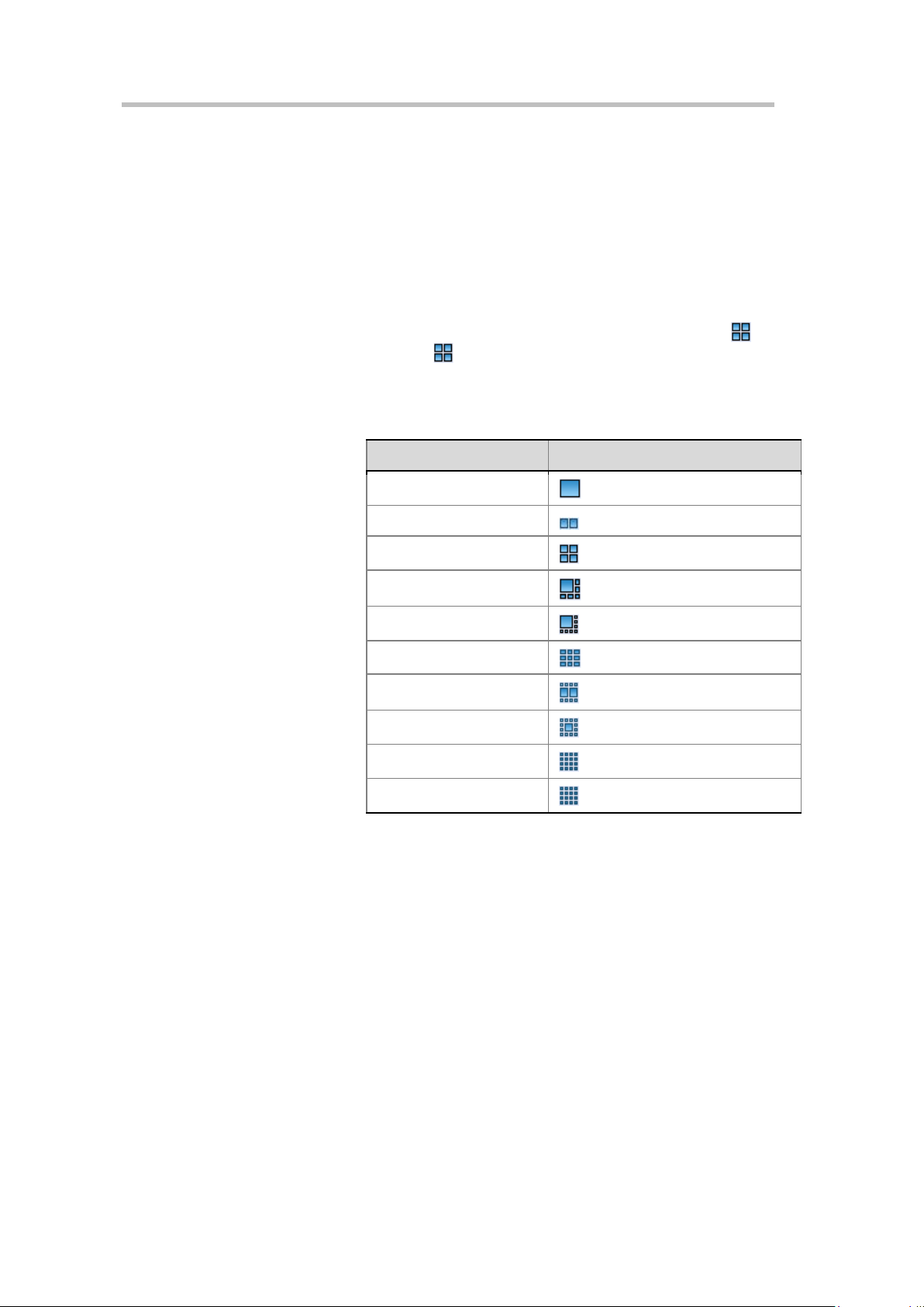
Chapter 4 –
Number of Participants
Multi-screen Layout
2
Conference Profiles
2 Select the largest multi-screen layout so that the conference site displays at
most the number of multi-screen windows set here. In this mode:
― When the number of participants is smaller than or equal to the set
number of multi-screens, the system displays the multi-screen image
according to the actual number of participants and in line with the
default rule. The table below shows the default rule.
― When the number of participants is greater than the set number of
multi-screens, the system uses the largest multi-screen layout to
display the first participants who speak the loudest. If the number of
participants is greater than 4 and the maximum selection is , the
system uses the layout to display the first four participants who
speak the loudest.
Default Rule of Automatic Layout
1
3-4
5-6
7-8
9
10
11-13
14-16
16+
If the Symmetric Layout option is selected, the system can only provide a
multi-screen layout with the same size windows.
To specify a fixed multi-screen layout:
1 To expand the corresponding multi-screen layout profile, click the left
part of multi-screen setting area the number of multi-screen windows to
be displayed
Audio Setting
4-14
2 Select a multi-screen layout so that the conference site displays the
participant's image always according to the layout selected here.
If the Symmetric Layout option is selected, a user can only select the multi-screen layout with the same size windows.
Click the Audio Setting tab on the New Profile page to set the audio
algorithms supported by the RMX system.
Page 50

User Guide for Polycom® RMX™ 500 and Polycom® RMX™1000 Systems
Parameter
Description
Parameter
Description
If an RSS is available on your network, you can select this
If you want to specify a recording link to use one of the VRR
default VRR parameter for RS S. For mor e informa tion on VR R,
recording manually. A fter this option is selected, the
Select an option on the page to enable the corresponding audio algorithm capability for the system.
Conference Skin Skins
Click the "Skins" tab in the "New Profile" interface to enter the interface for
skin settings. Here, you can define the background picture and outline color
of the multi-screen image, and browse the skin effect in the browsing area at
the lower part of the interface.
Customize settings for the conference skin by referring to the table below:
Parameter Description of Conference Skin
Background Picture Select the background picture for the conference screen.
(Conference on Ports)
Outline Color
Full screen
A user can respectively set the outline colors of screens for
the conference lecturer and regular participant.
When this option is selected, multi-scre ens will ex tend the full
screen, without spacing.
Conference Recording
RMX can work with Polycom RSS recording server to record conferences.
Click the "Recording" tab on the "New Profile" interface to enter the related
information and set the recording parameters.
The table below explains the configuration parameters.
Conference Recording Configuration
Enable Recording
Recording System
Address
Recording System
Alias
option to enable the recording function.
Enter the IP address of the RSS system to be connected. This
item is optional if an alias is set in the Alias check box below.
Enter the E.164 number or H.323 alias of the RSS in
accordance with the selected alias type. This item is optional if
the IP address of the RSS 2000 is set.
Note:
If the alias is used for recoding call, both RMX and RSS
need to be registered to the same gatekeeper.
Alias Type Set the alias type of the RSS: H.323 or E.164.
Recording System
Extension
Start
parameters on RSS, please enter the number for that VRR. If
no parameters are specified, the recording link will use the
please refer to the user manual included with the RSS system.
Select the start time of the conference recording:
• Immediately – T he r ecording automatical ly start s
immediately after the first participant joins the conference.
• Upon Request – The operator or chairper son starts the
4-15
Page 51

Chapter 4 –
recording can be manually started through the Web interface
system will terminate the conference when the rec ording fails or
• The Recording Link occupies one participant connection r esou rce.
Select this option to en able message over lay. Then you can set
Display Times
Move the slider to set the displ ay times of th e me ssage overl ay.
Parameter Description
Conference Profiles
or DTMF function. For more information, see Recording
Control.
People Video
Terminates a
conference when
recording fails or
no H.323 Links are
available in a
conference.
• If the encryption function is enabled in the "Conference Profiles->General"
interface, the recording will succeed only when the recording server also
supports encryption.
Overlay
You c an select to record the video for which channel of video
stream capability, or the audio only.
Selecting this option is not recommended if you are not
specifically required to do so. If this option is enabled, the
no H.323 links are available.
When a message needs to be sent to all the participants in a conference, you
can set the message overlay of conference to be displayed on all participants’
endpoint screens.
Click the "Message Overlay" tab on the "New Profile" interface to set the
message overlay parameters.
Set the message overlay with reference to the table below:
Message Overlay Setting Parameters
Parameter Description
Enable
Contents Enter the content to be displayed.
Font Size Set the font size of the message overlay.
Color
Display Speed
Vertical Boundary
Transparency Move the slider to set the contrast of the message overlay.
other parameters.
Set the color matching scheme for the message overlay font
and background.
Move the slider to set the display speed of the message
overlay. If the display speed is set to 0, the message will be
displayed in the center of the screen as a banner.
Move the slider to set the vertical boarder of the message
overlay.
4-16
Page 52

Site Name
Parameter
Description
Font Size
Set the font size for a site name.
Color
Set the text and background color schemes for a site name.
Overlay Position
Set the display position of a site name on the screen.
Vertical Boundary
Move the slider to set the vertical border of a site name.
Transparency
Move the slider to set the contrast of the site name.
Site Name
User Guide for Polycom® RMX™ 500 and Polycom® RMX™1000 Systems
(Conference on Ports)
A user can set the conference to display each of the site names (endpoint
names) on the conference screen, so as to mark each site in the viewed screen.
The site name displayed at each participant's endpoint comes from the
system name set for the endpoint.
To set a site name, click the Site Name tab on the New Profile page to enter
the settings page for site names. Here, you can specify the displayed
strategies, positions and color matching schemes for site names.
Parameter Description for Site Name Settings
Set the display strategy for a site name:
• Auto: a site name will be displayed and automatica lly
disappear in about 10 seconds if there are no changes to th e
conference video layout.
• Enabled: always displays a site name.
• Disabled: no site names are displayed.
Horizontal
Boundary
Move the slider to set the horizontal border of a site name.
Modifying a Profile
To modify a saved profile, right-click it in the Profile list, and then click
"Profile Properties" to modify its properties.
Deleting a Profile
To delete an existing profile, select it in the Profile list, and then click .
Alternatively, right-click the profile to be deleted and then click "Delete
Profile".
A profile in use cannot be modified or deleted.
4-17
Page 53

Chapter 4 –
Conference Profiles
Setting a Default Profile
After a default profile is set, the endpoint will use it when creating a
conference directly through the remote control. In addition, when a user
creates a meeting room, reserves a conference, or holds an instant conference
via the Web interface, the default profile will be used unless otherwise
specified.
To set a default profile, right-click the profile to be defined in the Profile list,
and then click "Set as Default". After that, the icon of the profile becomes .
A profile with the AES encryption function enabled c annot be set to a def ault profile.
4-18
Page 54

Recording Link
The RMX supports the recording link function. It can work with the Polycom
RSS to record conference content. After the recording setup is completed,
when the conference starts, the RMX will first call the participants in the
participant list, and then call the configured RSS to record the conference. The
recording link is displayed in the List pane as a regular participant, thereby
enabling users to view and control the recording status easily.
RMX allows you to use different RSS systems for recording in different
conferences. There are many ways to configure RSS recording servers on
RMX. You can enable recording and configure relevant parameters on the
settings pages for conference profiles, meeting rooms, reservations or
temporary meetings.
5
Configurations for Default Recording Parameters
You can configure a default RSS recording server on RMX to help reduce the
duplicate configurations for common recording parameters in conference
profiles. Every time a new conference profile is created, the profile's
configuration page for recording will use the default RSS system parameters
unless they are manually modified by users.
In the RMX Management pane, click "Recording Link". The Recording Link
interface appears in the list pane located on the right side. Here you can view
the IP address and alias configured for the RSS.
Recording Link
5-1
Page 55

Chapter 4 –
Conference Profiles
Right-click the default empty link or configured RSS IP address in the interface, and then click Properties to display the Recording Link-General interface.
General Settings
Recording Link - General Settings
The table below explains the detailed meanings of these parameters.
Recording Link - Description for General Settings
Parameter Description
Recording System
Address
Recording System
Alias
Alias Type Set the alias type of the RSS: H.323 or E.164.
Recording System
Extension
Enter the IP address of the RSS system to be connected. This
item is optional if an alias is set in the Alias check box below.
Enter the E.164 number or H.323 alias of the RSS in
accordance with the selecte d alia s type. T his ite m is option al if
the IP address of the RSS 2000 is set.
Note:
If the alias is used for recordi ng c all , bot h RMX and RSS
need to be registered to the same gatekeeper.
If you want to specify a recording link to use one of the VRR
parameters on RSS, please enter the number for that VRR. If
no parameters are specified, the recording link will use the
default VRR parameter for RS S. For mor e informa tion on VRR,
please refer to the user manual included with the RSS system.
5-2
Page 56

User Guide for Polycom® RMX™ 500 and Polycom® RMX™1000 Systems
Set the rights of u sin g DTMF codes. Chairper son i ndi cate s t h at
DTMF Code Setting
To set the recording control operations and rights for use by connected
endpoints, click the DTMF Codes tab.
Recording Link - DTMF Codes
The table below explains the detailed meanings of these parameters.
Recording Link - Description for DTMF Code Setting
Parameter Description
Name Name of the recording operation
(Conference on Ports)
Set the remote control key combination used to perform the
operation. The default numbers can be customized. For
example, the default DTMF code for the Start Recording
DTMF Code
Privilege
command is *2, you can press the keys *2 to start conference
recording.
Note:
Before using the DTMF command, enable the DTMF
function of the endpoint according to that endpoint's
instructions.
the DTMF is available to the conference chairperson only;
Everyone indicates that the DTMF is available to all
participants.
Recording Control
When a conference is going on, you can view and control the status of the
configured recording link. In the Conferences list pane, select this conference.
Then the list pane located on the right side shows the defined participants
and connected participants in the conference, where the recording link is
indicated by the icon.
When a conference is going on, you can control the recording as follows
through the recording buttons in the list pane or the right-click shortcut menu
of recording link:
• - Start Recording
• - Pause Recording
• - Stop Recording
• A conference chairperson can a lso use the PCM interface for recording control.
For more information, see Recording a Conference.
5-3
Page 57

Chapter 5 –
• For more information about the recording control operations of the RSS, see
Recording Link
RSS User Guide.
Recording Properties
To view the status between the recording link and RMX, double-click the recording link, or right-click it and select "Properties" to view parameters.
• General – Displays the name, address, alias and other information of RSS
system.
• DTMF Codes – A participant can use DTMF codes to send real-time
commands to an RSS server so as to facilitate the recording operations.
• Connection Status – Displays in real time the RSS-RMX connection status
and disconnection cause.
5-4
Page 58

Meeting Rooms
A Meeting Room is a conference saved on the MCU in passive mode, without
using any system resources. A Meeting Room is automatically activated
when the first participant dials into it. Once activated, a Meeting Room
functions as any ongoing conference. All Meeting Rooms are based on a
Conference Profile. The RMX can support up to 5000 meeting rooms.
To set a meeting room, click "Meeting Room" in the RMX Management pane.
The list pane shows the meeting rooms saved on the current system and their
summaries, such as the name, number, duration, conference password,
chairperson password, and the conference profile name for the meeting room.
Here you can create, modify and delete meeting rooms.
6
Meeting Rooms List
Creating a Meeting Room
To create a meeting room, click the button in the list pane, or right-click in the
blank area of the pane and then click "New Meeting Room". The "New
Meeting Room -> General" interface pops up.
6-1
Page 59
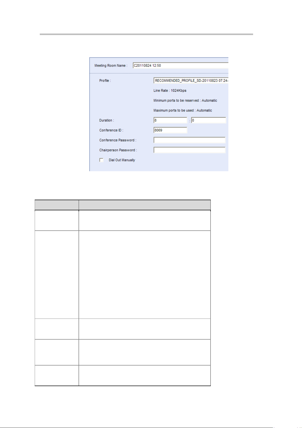
Chapter 6 –
Parameter
Description
Set a unique name to identify the meeting room. When a
meeting room is create d, the system w ill automatica lly generate
video quality. For more information on conference profiles, see
Meeting Roo ms
General Settings
New Meeting Room - General
Meeting Room
Name
Profile
Conference
Duration
The table below explains the detailed meanings of these parameters.
Parameter Description for New Meeting Room – General
a unique name for it.
Select the profile to be used for this conference from the
drop-down list. The lower part of this option displays the major
parameter values defined for the profile:
• Line Rate: the maximum bandwidth used by a participant in a
conference;
• Minimum Number of Reserved Resources/M ax imum
Number of A v ailable R esour ce s: t he mini mum/maximum
number of video participants to join a conference. Automatic
indicates that the number of video participants is det ermined
according to the available resource of the RMX.
The conference profile defines the basic parameters of
conference scheduling, such a s the bandwidth, encryption, and
Conference Profiles. When a conference is created, the syst em
selects the default profile by default.
Specify the conference dur ation in th e range of 0-24 hour s. The
input format is H:M and the default value is 8:0, namely, 8
hours.
When a meeting room is created, the system automat ically
Conference ID
Conference
Password
allocates a conference ID. You can also set a unique
conference ID on the device. To directly dial into the
conference, the participant must know its ID.
Enter the conference password. To connect to this conference,
the participant must enter this password. If this parameter is
empty, it means the conference has no password.
6-2
Page 60

Parameter Description
participants defined in the meeting room to join the conference
Enter the password that identifies the chairperson ID. The
Chairperson
Password
Manual Dial-out
system will authorize more rights to the chairperson. If this
parameter is empty, it means the conference has no
chairperson.
When enabled, the system will not automatically call the
unless the administrator dials out manu ally.
Participant setup
A user can add a participant to the participant list for the meeting room.
When this meeting room is activated and running, the system will
automatically call the participants defined in the meeting room to join the
conference. To set the invited participant list, click the Participants tab to
enter the relevant interface, as shown below.
User Guide for Polycom® RMX™ 500 and Polycom® RMX™1000 Systems
(Conference on Ports)
New Meeting Room - Participants
You can add participants to the list in the following two modes:
To create a participant in the list:
1 Click the "New" button to create a participant.
2 The popup configuration interface is the same as that for adding a new
participant to the address book. For explanation on the configuration
parameters, see Creating a Participant in the Address Book.
To add a participant from the address book to the list:
1 Click the Add from Address Book button.
2 In the popup address book, select the participant to be added, and then
click the "OK" button. To select multiple participants at one time, click
6-3
Page 61

Chapter 6 –
Parameter
Description
Mode, all participants ’ endpoint s display t he lecturer in
automatically send an em ail m ess age t o no tif y ea ch p arti cip a nt
Meeting Roo ms
these participants one by one while pressing down the "Ctrl" key, or select
adjacent ones while pressing down the "Shift" key.
A user can select the participant to be added, and then specify in the
"People Video" field which channel of audio and video stream capability
defined on the conference profile will be used by the participant to join
the conference. If the participant's endpoint does not support the
specified video stream capability, it will be connected with the highest
video stream capability supported by it.
To edit or delete a participant that is added to the list, select it, and then click
the "Edit" or "Remove" button. A user can also click multiple participants to
be deleted one by one while pressing down the "Ctrl" key, or select adjacent
ones while pressing down the "Shift" key.
The table below shows the meanings of other optional parameters.
Parameter Description for New Meeting Room – Participants
- This option is available only when the video mode for
the conference profile of meeting room is set to
Lecture Mode. About settings of the video mode, see
Video Setting.
- After adding participants to the list, you can select a
participant from the drop-down list to act as the
Lecturer
lecturer. The default setting is "Auto", when the
system will use the voice activation feature to
automatically select the lecturer.
- When the conference is running under the Lecture
Dual Stream
Sender
Allows Only
Endpoints in the
Participant List to
Dial in
Send Email
Notifications
Recording
full screen, and the lecturer’s endpoint can switch to
display other conference sites in rotation.
Select a fixed dual stream sender. Only a selected participant
can send dual streams in the conference. Auto by default,
meaning that all participants can send dual str eam s.
When this option is selected, o nly the partic ipants defined in t he
Participant List can dial into the conference.
If this option is selected, after you click OK, the system will
in the Participant List to join the conference. This option is
enabled only when SMTP is configured in the "IP Network
Services->Email" interface. For more information, see
Email.
By default, a meeting room will use the recording parameters configured in its conference profile. You can also manually configure the recording parameters for a meeting room. To set your recording parameters, click the Recording tab.
For meanings of the configuration parameters on this page, see Conference
Recording Configuration.
6-4
Page 62

User Guide for Polycom® RMX™ 500 and Polycom® RMX™1000 Systems
Parameter
Description
software RMX Multicast Player to p lay confer ence vide os on y our
Set the multicast address and port number used for sending
Select the videos from a specific video stream channel for
In the event of severe packet l oss a t the m ult ica st re ceiv in g s ide ,
Multicast Configurations
RMX supports multicasting to computers within a LAN. You can watch
real-time conference videos by using special multicast receiving software on
your computer. To set your multicast, click the Multicast tab.
New Meeting Room - Multicast
Parameter Description for New Meeting Room – Multicast
(Conference on Ports)
Enable
Multicasting
Password
Address
People Video
LAN1/LAN2
Enable I Frame
Suppression
If this option is selected, the system will start multicasting while
this conference is held. You can use the multicast receiving
computer. For more information, see the following section.
Set multicasting passwords. Same passwords need to be
configured on multicast receiving computers for participants to
watch their videos. This item is optional.
conference videos.
multicasting.
Select computers for multicasting within a LAN where the
system's LAN1 port or LAN2 port is located.
Note:
If port LAN1 and LAN2 are configured within the same
network, they should not be selected simulta neo usly.
the computer will frequently send I frame requests to MCU and
this will affect the conference's graphic effects on MCU. When
the I frame suppression function is enabled, MCU's I frame
response to the computer can be suppressed. To enable this
option, you need to enter the I frame suppression interval, i.e.,
how often MCU responds to an I frame request.
Use the RMX Multicast Player Tool to Receive Multicast
Before using RMX Multicast Player to receive multicast, please configure the
firewall in your computer to allow multicast streams to pass through.
6-5
Page 63

Chapter 6 –
Meeting Roo ms
1 Run the RMX Multicast Player.exe file on the CD included with your
computer. Install as prompted by the software installation interface.
Usually you can just use the default settings.
2 When you complete your installation, click Start -> All Programs -> RMX
Multicast Player to run the multicast receiving tool on your computer. The
software opens two windows: a video playing window and a multicasting
control window, as shown below.
RMX Multicast Player Interface
3 In the multicasting control window, click the Open button to enter the
dialog box for multicasting parameter settings.
The dialog box for multicasting parameter settings
4 Set the following parameter options:
― IP Address: the IP address for receiving multicasting conference
videos. This address must be identical to the multicast address
configured on RMX.
― Start Port: the port number for receiving multicasting conference
videos. This port number must be identical to the multicast port
number configured on RMX.
6-6
Page 64

User Guide for Polycom® RMX™ 500 and Polycom® RMX™1000 Systems
― Encryption Password: if a multicast password has been configured
on RMX, the same password must be entered here.
5 Click the OK button. When a multicasting-enabled conference is held on
RMX, the RMX Multicast Player will receive the conference video from
the specified multicast address and play it in the video playing window.
When necessary, you can complete the following control operations in the
multicasting control window:
• Adjust the volume
You can use the volume slider in the multicasting control window to
adjust the volume. Press Mute to mute the video.
• Adjust the video window
Click Window Size to set the window to display in 100%, 200% or full
screen. You can also move your cursor to the edge of the window, and
then drag and move it to adjust the window to the desirable size when an
adjustable symbol appears.
• Check the video statistics
(Conference on Ports)
Click the Status button to display the transmission rate, frame rate, I
frame requests, etc. for the current video in the video playing window.
• Request I frames
In the event of severe packet loss, click Request I Frames to send your I
frame request to MCU to improve the video quality. If Auto is selected,
the multicast tool will automatically request I frames in the event of
packet loss. Frequent I frame requests will affect the conference's video
quality on MCU. As a result, this option is not usually recommended.
Other Information
To configure other information for the meeting room, click the Information tab. Here you can configure conference notes, site details, accounting information, etc.
Modifying a Meeting Room
To modify a meeting room, double-click the desired meeting room in the
meeting room list; or right-click the meeting room, and then click Meeting
Room Properties. For explanation on the configuration parameters, see
Creating a Meeting Room.
Deleting a Meeting Room
To delete a meeting room from the device, select the meeting room to be
deleted in the meeting room list, and then click the button, or right-click
the meeting room, and then click "Delete Meeting Room".
6-7
Page 65

Reservations
Multiple types of conference reservations can be implemented using RMX. A
user can reserve a one-time or permanent conference, or hold routine
conferences on a daily, weekly, or monthly basis as needed. The system
reserves resources for conferences, so the conference can be automatically
started at the preset time. The RMX can support up to 1000 reservations.
To configure a reservation, click "Reservations" in the RMX Management
pane. The list pane shows the related configuration interface. The reservation
function provides two configuration views: the calendar view and list view.
7
Reservations
Reservation Views
Calendar View
The calendar view is displayed by default. It shows the distribution of
reserved conferences in standard time sequence on current RMX through a
calendar familiar to users. Under the calendar view, a user can switch to
display the reservation information in each time segment by “Today”, “Day”
or “Week”, and directly reserve a conference on a specific date to make
conference scheduling clearer. Under the reservation list view, click the
button to switch to the reservation calendar view.
7-1
Page 66

Chapter 7 –
Reservations
Switching Calendar Modes
Under the calendar view, the system can display the calendar by day or by week so that users can fast view reservations at each time segment. By default, the Week calendar is used to show the distribution of reservations.
To view the reservations per week:
1 At the "Today" or "Day" calendar mode, click the button to show the
reservations in a week.
2 When necessary, click the or button to show the reservations of
the previous week or next week.
To view the reservations per day:
1 In the Week calendar mode, click to display the conference on the
selected date in the current calendar.
Click now to show the conference reserved today.
2 When necessary, click the or button to show the reservations
on the previous day or next day of the current date.
List View
Under the reservation calendar view, click the button to switch to the
reservation list view. The list view shows all the reservations on the current
system in a list. A user can view all summaries of conferences, including the
conference name, dial-in ID of the participant, conference start time and
duration, conference password, chairperson password, and conference
profile.
Adding a Reservation
To reserve a conference:
• Under the calendar view, click the button on the pane, or right-click
at the blank area besides the selected calendar date and time, and then
click "New Reservation".
• Under the list view, click the button on the reservation list pane, or
right-click at the blank area, and then click "New Reservation".
On the New Reservation interface, you can set the basic conference
information, participants, reservation time and other related information. The
text below only describes the configurations for the Schedule tab. The
procedures for setting other tabs are the same as those for setting a meeting
room. For explanation on the configuration parameters, see Creating a Meeting
Room.
7-2
To set a reservation, click the "Schedule" tab to enter the reservation interface.
From the Schedule Mode drop-down menu, select the desired reservation
mode to reserve a permanent, once, daily, weekly, or monthly conference.
Page 67

Setting a Reservation Mode
7-3
Page 68

Chapter 7 –
Parameter
Description
Set the start time of the conference in the format of H:M.
Conference
Reservations
Reserve a Permanent Conference
A permanent conference can be manually terminated or deleted by a chairperson or web UI user.
To reserve a permanent conference, set the Schedule Mode to Permanent. Set
the start date and time for a conference in the page.
Reserving One-time Conference
The one-time conference will be terminated after being held for a specified
period of time. To reserve a one-time conference, set the Schedule Mode to
Once. The table below explains the configuration parameters.
Parameter Description for Reservation Setup – Once
Parameter Description
Start Date Set the start date of the conference.
Start Time Set the start time of the conference in the format of H:M.
Conference
Duration
Set the duration of the conference in the format of H:M.
Reserving a Daily Conference
To reserve a daily conference, set Schedule Mode to Daily.
The conference will be convened at the specified time every day. In the
specified period, this reservation is also deleted when the last conference is
terminated. The table below explains the configuration parameters.
Parameter Description for Reservation Setup – Daily
Start Time
Duration
Start Date Set the start date of the recurrence range of the reservation.
End Date Set the end date of the recurrence range of the reservation.
Set the duration of the conference in the format of H:M.
Reserving a Weekly Conference
To reserve a monthly conference, set Schedule Mode to Monthly.
The set conference will be convened at the specified time per week. In the
specified period, this reservation is also deleted when the last conference is
terminated. The table below explains the configuration parameters.
Parameter Description for Reservation Setup – Weekly
Parameter Description
Start Time Set the start time of the conference in the format of H:M.
Conference
Duration
Set the duration of the conference in the format of H:M.
7-4
Page 69

User Guide for Polycom® RMX™ 500 and Polycom® RMX™1000 Systems
Parameter
Description
convened. Multiple week days can be selec ted. I f you se lect t he
Mon. and Fri. check b oxes, the conference will be aut omatical ly
Parameter
Description
Start Time
Set the start time of the conference in the format of H:M.
Conference
Set the end date of the recurrence range of the reservation.
Specify the day of mont h on which the reser ved c onferenc e w ill
At the specified time, the reserved conference will be convened automatically, the
can be viewed
but cannot be modified. In addit ion, the confer en ce li st will show that the conference is
ongoing.
Start Date Set the start date of the recurrence range of the reservation.
End Date Set the end date of the recurrence range of the reservation.
Specify the weekday on which the reserved conference w ill b e
Sunday - Saturday
started at the specified time on every Monday and Friday.
Reserving a Monthly Conference
To reserve a weekly conference, set Schedule Mode to Weekly.
The conference will be convened at the specified time per month. In the
specified period, this reservation is also deleted when the last conference is
terminated. The table below explains the configuration parameters.
Parameter Description for Reservation Setup – Monthly
(Conference on Ports)
Duration
Start Date Set the start date of the recurrence range of the reservation.
End Date
Conference Date
Set the duration of the conference in the format of H:M.
be convened. If you enter 1, the conference will be
automatically convened at the specified time on the first day of
every month.
conference icon will become , and the properties of the conference
Modifying a Reservation
You can modify a reserved conference before it is convened.
To modify the parameters of a reservation:
In the reservation calendar view or list view, double-click the reservation to
be modified or right-click this reservation and then click "Reservation
Properties" to enter the reservation parameter setting interface. For the
meanings of related configuration items, see the previous section Adding a
Reservation.
7-5
Page 70

Chapter 7 –
Reservations
Deleting a Reservation
You can delete a reserved conference before it is convened.
Deleting a Reservation:
• In the reservation calendar view, select the reservation to be deleted from
the calendar, and then click the button, or right-click this reservation
and then click "Delete Reservation".
• In the list calendar view, select the reservation to be deleted from the list,
and then click the button, or right-click this reservation and then
click "Delete Reservation".
For a one-time reservation, you need to confirm in the popup message box
whether to delete it or not.
For a recurring reservation:
• If under the calendar view, you need to confirm in the popup message
box whether to delete this specific reservation or all the events of this
recurring reservation;
• If under the list view, you need to confirm in the popup message box
whether to delete this specific reservation or all the events of this
recurring reservation.
7-6
Page 71

Address Book
You can use the address book provided by the RMX to store participant
information, such as the IP address and network communication protocol of
the participant's endpoint. The address book enables you to conveniently and
easily add participants to a conference.
The grouping function of the address book simplifies the creation of a
conference. Different from the function of adding a single participant to the
conference, the grouping function can be used to quickly add two or multiple
participants to the conference at the same time.
If the RMX system is registered to a directory server, the address book
contains the following two types of directories:
8
• Local Directory: The information of conference sites added by users
through the Web management interface of RMX. This kind of address
entries are saved in the local RMX system, and can be edited, deleted, or
exported by users.
• Global Directory: the global address book entries stored on the external
directory server which have been integrated with the RMX system. These
address entries are stored in the directory server, and cannot be edited.
Located in the rightmost part of the Web interface, the Address Book pane
shows the participant information stored in the address book. A user can
perform multiple operations through the toolbar buttons at the upper part of
the pane (e.g. creating a participant, defining a participant group, deleting a
participant or participant group, refreshing the address book, switching to
display the address on the local or directory server, importing/exporting the
address book, and searching a participant).
Address Book
8-1
Page 72

Chapter 8 –
Address Book
Adding a Participant to the Local Directory
You can add the information of a new participant to the local directory in the
following two ways:
• Create a participant in the address book.
• Add a participant in the ongoing conference to the address book.
Creating a Participant in the Address Book
Click the button on the Address Book pane to add a new participant,
and enter the "New Participants-> General" interface.
General Settings
8-2
New Participants – General
Page 73

User Guide for Polycom® RMX™ 500 and Polycom® RMX™1000 Systems
Select the network communication protocol used when the
participant's endpoint dials in to the conference: H.323 or SIP.
If the network type i s set to H.3 23, select the alias type of H.323
If the RMX is the master, select Master, otherwise select Slave.
Enter a DTMF code that will be sent upon connection to the
To add a participant who can communicate only through Polycom VBP (previously
known as V2IU), you need to enter the IP address of V2I U in IP Address and the E.164
number of endpoint in Extension. Only in this way can the system suc cessfully call this
participant.
The table below explains the detailed meanings of these parameters.
Configuration Description of New Participants – General
Parameter Description
Name Enter a name to identify the participant.
If the network type is set to H.323, enter the IP address for the
IP
Address/Routing
Address
participant's endpoint.
If the network type is set to SIP, enter the routing address for
the participant's endpoint.
This item is optional if an H.323 alias or SIP address is set in
the "Alias"/"SIP address" check box below.
(Conference on Ports)
Type
Alias/SIP Address
Cascading
Dialing Direction
Extension
The option in the "Alias"/"SIP Address" check box will change
along with the network type selected here.
or E.164 in the right drop-down list, and then enter the related
alias.
If the network type is set to SIP, select the SIP address type in
the right list, and then enter the related address.
This item is optional if the IP address of the endpoint is set.
If the device is a standard endpoint, select No Cascade.
If the device will be a cascaded link to another MCU, set the
master/slave relations hip of the RMX relative to the participant:
In the cascading mode, you need to set the following three
items: Dialing Direction, Extension and DTMF.
Select the dialing direction:
• Dial-in: The participant's device dials in the conference at the
local RMX. It is unnecessary to set the items Extension and
DTMF if this option is selected.
• Dial-out: The local RMX dials out t o the participa nt ’ s dev ice.
Note:
the Dialing Direction option is available only if the
Cascading option has been set to Master or Slave.
Use this field in case the user would like to send an extension
field to the remote end.
Password
Audio Only
remote end.
If this option is selected, the participant will be defined as an
audio participant, and the system does not support video input
and output capabilities.
Example of cascading configuration
8-3
Page 74

Chapter 8 –
Address Book
There are two sets of cascaded RMX devices (RMX_1 and RMX_2). The
information is as follows:
RMX_1
IP: 172.22.176.9
E.164 Prefix (Register to a GK): 80
ID of Master Conference (Dial out from): 1234
RMX_2
IP: 172.22.176.10
E.164 Prefix (Register to a GK): 80
ID of Master Conference (Dial into): 2222
Password of Master Conference (Dial into): 1111
To set the RMX_1 as the master device and dial to the conference at the
RMX_2, perform the following configuration at the RMX_1:
8-4
Cascading Configuration – RMX_1
At the same time, configure as follows at the RMX_2:
Page 75
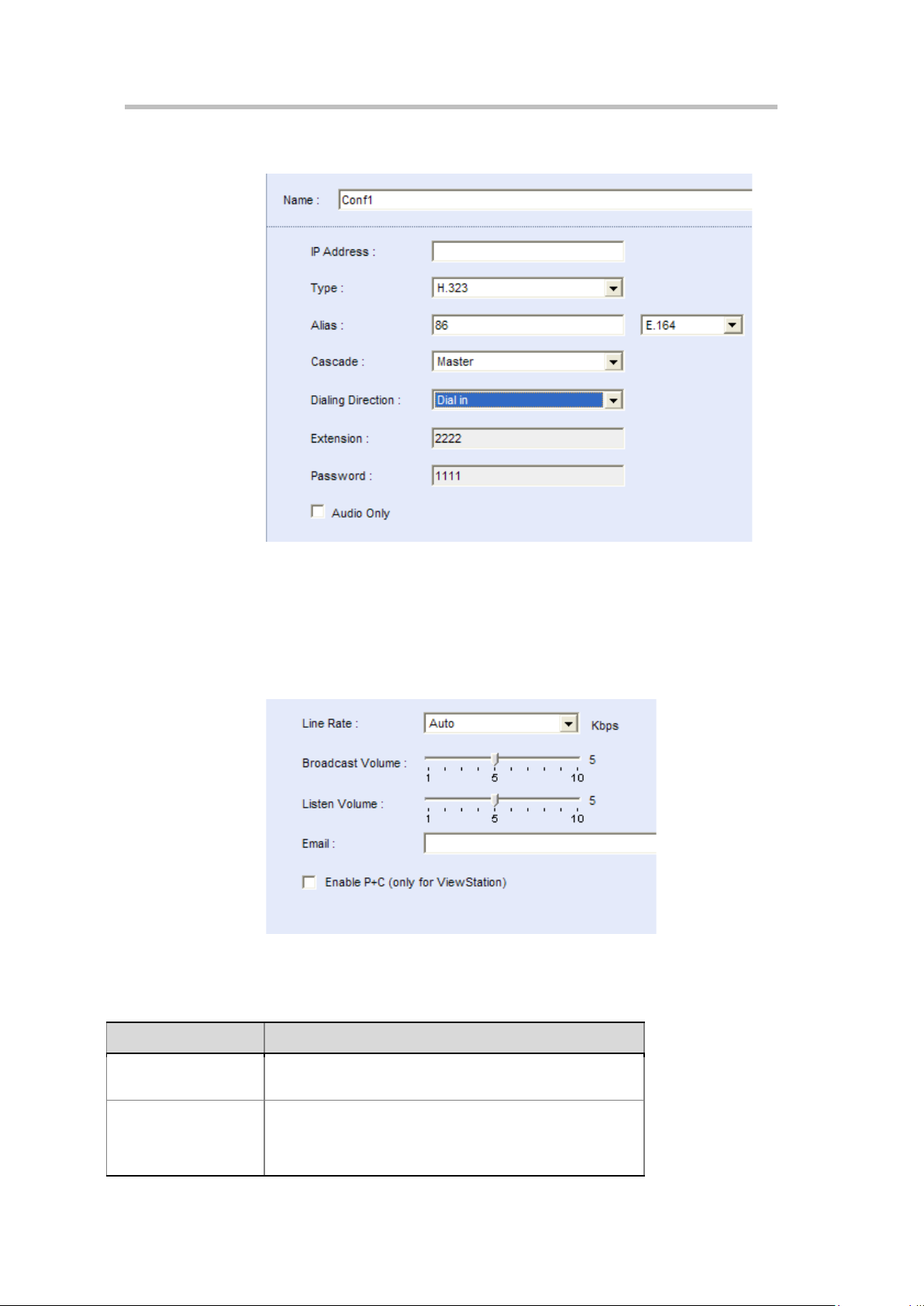
User Guide for Polycom® RMX™ 500 and Polycom® RMX™1000 Systems
Parameter
Description
Specify the line rate of the participant’s endpoint. "Auto"
Move the corresponding slider to adjust the volume
1~10 (in the ascending order), while the default value is
(Conference on Ports)
Cascading Configuration – RMX_2
Advanced Setting
Usually, you only need to set the parameters on the General tab, and accept
other default settings of the system. However, to set advanced parameters,
click the Advanced tab.
New Participants - Advanced
The table below explains the configuration parameters.
Configuration Description of New Participants – Advanced
Line rate
Broadcasting/Listening
Volume
indicates using the line rate specified by the RMX system.
transmitted/received by the participant. Each grid increa ses
or decreases the sound by 3dB. The adjustable range is
8-5
Page 76

Chapter 8 –
5dB.
Set the Email address used by the participant to receive
Parameter Description
Email Address
Enable P+C
Address Book
conference notices from the system. Up to 2 Email
addresses can be set by separating them with a “;”. For
example, enter
address1@polycom.com;address2@polycom.com.
Used only for the Polycom ViewStation series endpoints.
The ViewStation series endpoi nts can sen d and receiv e
dual streams in a conference only if this option is selected.
Other Information
To add other information for the participant such as c o mpany name and contact phone, click the Information tab and configure Info1~Info4, then click OK.
Adding a Participant from an Ongoing Conference
You can also add a participant in an ongoing conference to the local directory. Operate as follows:
1 Click the desired conference in the Conferences list pane. 2 On the list pane, select the participant to be added, and then click the
button or right-click the participant, and then click "Add Participant to
Address Book".
Defining a Participant Group
A group is a collection of pre-defined participants. With the grouping
function, you can conveniently add a group of participants to the conference.
For example, to frequently hold conferences of the marketing department,
you can create a group named “Marketing Team” that contains the endpoints
of all the marketing department participants. You can invite all the members
to the conference to be held.
To define a group:
1 In the Address Book pane, click the button or right-click in the blank
area, and then click "New Group".
2 The New Group page appears. Enter the name of the group in the "Group
Name" field, e.g. “Marketing Team”.
3 Click Add From Address Book. In the participant list that appears, select
the desired participant, then click OK.
To select multiple participants at one time, click the desired participants
one by one while pressing down the Ctrl key, or select adjacent ones
while pressing down the Shift key. To delete an added participant from
the group, select it and click Remove.
4 You can also delete multiple participants from the group. Click OK on the
New Group page to add the new group to the address book.
8-6
Page 77

User Guide for Polycom® RMX™ 500 and Polycom® RMX™1000 Systems
Modifying a Participant/Group
To modify the participants or groups stored in the local directory, right-click
the participant or group to be modified in the list and then click Participant
Properties or Group Properties to display and modify the detailed
parameters.
Deleting a Participant/Group
To delete a participant or a group from the local directory, click the
participant or group to be deleted in the list, and then click the button.
Alternatively, right-click the participant or group, and then click "Delete
Participant" or "Delete Group". In the confirmation dialog box that appears,
click "OK".
You can also select the participant or group to be deleted, and then press the “Del” key to delete it.
(Conference on Ports)
Importing and Exporting the Local Directory
Exporting the Local Directory
A user can export entries from the local directory as a .csv file, for the purpose
of backup or sharing between RMX systems.
To export the local directory:
1 Click the button at the upper part of address book pane. 2 The dialog box for downloading file appears. Click "Save". 3 Select or enter the path of saving this file at the local computer, and then
click "Save". The local address book will be saved at this specified path as
a .csv file.
The groups defined in the address book cannot be ex por ted.
Importing the Local Directory
To import the local directory:
1 Click the button at the upper part of address book pane.
2 The interface for importing the address book appears. Click "Open".
3 Select or enter the path where the address book file (.csv) to be uploaded
is located, and then click "Open" to return to the interface for importing
the address book.
4 Click "Upload".
8-7
Page 78

Chapter 8 –
When uploading an address book file, the participants in the current address book
Address Book
won't be overwritten by entries with identical par ticipant names in the uploaded file.
Internal GK server
The RMX system has been successfully integrated with internal GK server
from version V2.4.3, which allows endpoints register RMX as its gatekeeper.
Internal GAB server
The RMX system has been successfully integrated with internal GAB server
from version V2.5.0, which allows endpoints register global directory service
or GAB to RMX from endpoint side.
Directory Service
If the RMX system has been successfully integrated with a directory server,
the information for other sites registered to this directory server will be
synchronized to the address book for RMX. The RMX system allows you to
register to the GAB or LDAP directory service provided by Polycom CMA™
v4.0 and internal GAB server.
Enabling Builtin GAB Server
In the Web interface, click the "Setup->Directory Service" menu item at the
upper left part to enter the Directory Service interface.
8-8
Page 79

User Guide for Polycom® RMX™ 500 and Polycom® RMX™1000 Systems
(Conference on Ports)
Select “Builtin Gab Server Setting”, the RMX can work as GAB server and
endpoints can get directory address by registering to it, enter the password if
any.
Configuring Directory Service
In the Web interface, click the "Setup->Directory Service" menu item at the
upper left part to enter the Directory Service interface.
Select the directory service type from the Type list. "None" is selected by
default, indicating that directory service is not used. Depending on different
directory service modes selected from "Type" by users, the system requires
configuring different parameters.
8-9
Page 80

Chapter 8 –
Parameter
Description
Server
Set the IP address of GAB server.
Address Book
GAB Server
To register RMX to the GAB server, select "GAB" from "Type".
Settings for the GAB server
LDAP Server
Configure the parameters according to the table below:
GAB Configuration Parameters
Password Enter the password (if available) of global directory.
To register RMX to the LDAP server, select "LDAP" from "Type".
8-10
Settings for the LDAP serve r
Page 81

User Guide for Polycom® RMX™ 500 and Polycom® RMX™1000 Systems
LDAP authentication type. Depending on different
Button
Function
This button is available when the gl obal director y list is dis played. Click
Configure the parameters according to the table below:
LDAP Configuration Parameters
Parameter Description
Server IP address of the LDAP directory server
Server Port LDAP server port No.
Base DN
(Distinguished
Name)
LDAP Base DN
(Conference on Ports)
Authentication
Type
Use SSL (Security
Socket Layer)
Domain Name LDAP server domain name
Bind DN
(Distinguished
Name)
User Name User name of the LDAP directory
Password Enter the password (if available) of LDAP directory.
authentication types selected by users, the system requires
configuring differen t option s.
Specify whether to use SSL secure transmission or not.
LDAP bind DN
After the configuration is finished, will be displayed if the directory
service is successfully registered, or else is displayed.
Viewing the Global Directory
After the directory server is successfully registered, the global directory
buttons ( ) on the address book pane will be activated. The
table below defines the functions of these buttons:
Function Definitions of Global Directory Buttons
The global directory will be automatica lly refreshed at regular interv als
to synchronize the address change on the directory server. You can
click this button to manually refresh the global dire ctory.
this button to switch to the local directory list.
This button is available when the dynamic GAB address is displayed.
Click this button to switch to the dynamic GAB address.
Display the local and dynamic GAB directory lists.
Click the button on the address book pane to display the global
directory list, as shown below. The list shows the information of other
endpoint sites registered to the directory server. The green icon indicates that
8-11
Page 82

Chapter 8 –
To return to the address book after searching, clear the entered keyword, and click to
Address Book
this endpoint can be used to dial in to the conference, and the grey icon
indicates that this endpoint is offline.
Global Directory List
Searching Directory Entries
A user can use the "Search" function of address book to fast find the specified participant or participant group when the address book stores the information of numerous participants.
To search for a participant or participant group, enter the name of participant
or participant group to be queried in the search box on the
address book pane, and click the button. You can enter the full name of
the participant or group for accurate searching or the keyword in this name
for fuzzy searching.
re-query.
8-12
Page 83

Conference/Participant
Parameter
Conference Information
The interface displays the conference name.
The interface displays the status of the ongoing conference. No
Monitoring
Through the real-time conference monitoring platform of the system, you can
easily monitor ongoing conferences; track participants and conference
progress, and perform control operations as needed. With the RMX, you can
implement two types of monitoring operations:
• Conference monitoring – On the main window, view the ongoing
conferences and information about the specified conference and specified
video, and change the conference control, management and other
parameters as needed.
9
• Participant monitoring – View the status and detailed parameters of
participants, change the multi-screen layout of the endpoint, and set a
message overlay to be viewed by the site.
Conference Monitoring
Viewing Conferences List Pane
The Conferences list pane always shows information about ongoing
conferences. The table below explains conference information.
Conference Information
Name
indication will be displayed if th e connect ion of pa rticipants is normal.
Corresponding indicators appear with a warning icon at the
occurrence of the following statuses:
• Audio – Problems with the parti cipant’s audio
• Empty – No participant is connected.
Status
• Faulty Connection – Participant s ar e conne cted, but the
connection is problematic.
Number The Conference ID assigned to the conference
Start Time Conference start time
• Not Full – Not all the defined par ticipants are connect ed.
• Partially Connected – T he conn ection process is not yet
complete, and the video channel has not been conne cted.
• Single Participant – Only one par ticipant is conne cted.
• Video – Problems with the participant’s video
9-1
Page 84

Chapter 8 –
Parameter
Conference Information
End Time The time the conference is expected to end
Address Book
For multi-screen conferences, you can click next to the conference name to
display details of the four video stream channels and one pure audio stream
channel, including the video protocol, video format and conference
bandwidth of each video stream. When you click each channel of video
stream or audio stream, the participant list will show the information about
participants that access the related conference with this channel of
audio/video capability.
Viewing Conference Parameters
In addition to the status information shown in the conference list, you can
view detailed parameters of an ongoing conference. Double-click the
conference to be viewed or right-click it, and then click Conference Properties.
The Conference Parameters interface shows the configuration of the
conference. Here you can change the end time, password and chairperson
password for the conference, adjust the conference layout, set the conference
message overlay, conference name and customized polling, etc. The
unavailable options cannot be modified.
Conference Control
Changing End Time
When a conference is created, its duration is also set. The default duration is 8
hours.
When a conference is occurring, you can extend or shorten its duration by changing its End Time. You can also manually delete an ongoing conference.
To change the conference duration:
1 Double-click the desired conference in the Conferences list pane. 2 On the General tab of the Conference Parameter interface, change End
Time, and then click OK.
The conference duration cannot exceed 720 hours (30 day s).
To manually terminate a conference:
9-2
1 In the conference list, click the conference to be deleted, and then click the
button, or right-click the conference, and then click "Delete
Conference".
2 In the confirmation dialog box that appears, click OK.
Page 85

User Guide for Polycom® RMX™ 500 and Polycom® RMX™1000 Systems
Locking/unlocking a Conference
When an ongoing conference is locked, all the endpoints cannot dial into the conference by themselves. After the conference is unlocked, any endpoint can dial into the conference.
To lock or unlock a conference, select one of the following two modes:
• Select the conference in the conference list, and then click the locking
button /unlocking button on the pane, or right-click the
conference, and then select "Conference Lock"/"Conference Unlock"
from the shortcut menu.
• Double-click this conference to enter the conference parameter interface.
On the "Advanced" tab interface, select or deselect the "Conference Lock"
check box.
Setting the Talk Hold Time
In the voice activation mode, if the talk of a participant reaches the set time,
this participant will be automatically set to the speaker. In different video
modes, different display rules apply to the speaker's endpoint:
(Conference on Ports)
• In the Lecture Mode, if a user sets to automatically select a lecturer
through voice activation, the speaker will become a lecturer and be
displayed in full screens at other participants' endpoints, and the
speaker's endpoint will display the screens of other sites.
• In the same multi-screen layout mode, the image outline at the speaker's
endpoint will be highlighted when multi-screen windows are at the same
size. While, if the multi-screen windows are at different sizes, the image
of the speaker's endpoint will be switched to the largest window.
To set the talk hold time, double-click this conference to enter the conference parameter interface. Enter the time in the "Talk Hold Time" text box on the "General" tab interface, in the range of 1-60 seconds.
Changing Conference and Chairperson Passwords
1 In the Conferences list pane, double-click the desired conference. 2 On the General tab, set Conference Password and Chairperson Password,
and then click OK.
Choose a personalized layout
You can change the multi-screen mode and multi-screen layout of an ongoing
conference. The initial multi-screen mode and screen layout of the conference
accords with the conference profile.
To select a conference multi-screen mode:
1 In the Conferences list pane, double-click the desired conference.
2 Click the "Video Settings" tab on the conference parameter interface.
9-3
Page 86

Chapter 9 –
Conference/Participant Monitorin g
3 Select the required mode in "Multi-screen Mode".
― Lecture Mode: All the participants’ endpoints will display the
lecturer in full screens, and the lecturer’s endpoint will display other
participants according to the layout set here. After this option is
selected, the "Lecture" option is activated. Specify a lecturer in the
drop-down list. "Auto" indicates that the voice activation feature will
be used to select the participant whose talk time reaches the defined
duration as the lecturer. For settings of the talk hold time, see Setting
the Talk Hold Time.
― Same Layout: All the participants' endpoints in the conference will
display the same multi-screen image according to the layout set here.
This setting will allow sites to see their own loopback images.
To set multi-screen layout:
Based on the selected multi-screen mode, a user can set to automatically
select the multi-screen layout according to the number of added participants
or specify a fixed multi-screen layout.
To set automatic multi-screen layout:
1 Click "Auto" at the left part of the multi-screen setting area to display the
automatic multi-screen layout pane.
2 Select the largest multi-screen layout so that the conference site displays at
most the number of multi-screen windows set here. In this mode:
― When the number of participants is smaller than or equal to the set
number of multi-screens, the system displays multi-screen image
according to the actual number of participants and in line with the
default rule. For the default rule, see Default Rule of Automatic Layout.
― When the number of participants is greater than the set number of
multi-screens, the system uses the voice activation feature, and
switches to display the first participants who speak loudest with the
largest multi-screen layout selected here. If the number of
participants is greater than 4 and the maximum selection is , the
system will display the first four participants who speak loudest
using the layout.
To set fixed multi-screen layout:
Click the desired layout number, and then select the desired layout. The
interface shows the thumbnail of the layout. For the video display in each
video window, you can select one of the following modes from the
drop-down list:
• Auto: This option is selected by default. Each multi-screen window will
automatically select to display a conference site based on the information
about connected participants.
9-4
• Automatic Polling: by default, if the set multi-screen number is smaller
than the number of connected participants, the window will display
images of the rest participants in turn. The administrator can also specify
the specific conference sites to be displayed in turn. For details, see
Customized Polling. The time interval for switching between the
conference sites is the value of Automatic Polling Interval.
Page 87

• Directly select an endpoint conference site to be displayed at the window.
• If the "Symmetric Layout" option is selected, a user can only select the
multi-screen layout with the same size of windows.
• In the Same Layout mode, participants will view the video of their conference
sites.
Set Viewers and Hosts
Define the viewers and hosts in a conference, in spite of the multi-screen mode strategy for a conference; specify the fixed target conference site for a participant to watch. This function has the following limitations:
• Used only for multi-screen conferences satisfying the following
conditions:
― Conferences using fixed multi-screen layout, with the number of
participants equal to the number of selected multi-screen panes plus 2
Conferences which are not in 16 multi-screen layout
― The multi-screen pane has been set to display a fixed conference site
― None of the video stream channels has a capability of H.263, 4CIF
User Guide for Polycom® RMX™ 500 and Polycom® RMX™1000 Systems
(Conference on Ports)
• The viewer must be an endpoint which uses the first channel of video
stream capability to access the conference.
• The endpoint which has been appointed as the chairperson cannot
become a viewer.
• If the conference is a single channel conference with a capability of 4CIF
or CIF, up to 7 endpoints can be displayed on the conference screen when
this function is enabled.
Set viewers and hosts:
1 In the Conferences list pane, double-click the desired conference. 2 Click the Video Settings on the conference parameter page. 3 Specify the viewers and hosts on the bottom of the page, and then click
OK.
Customized Polling
The administrator can customize a polling queue so that the multi-screen
window which has been set to do automatic polling can display the
conference sites one by one in the queue. The display sequence is the same as
the sorting sequence in a queue.
Set the polling queue:
1 In the Conferences list pane, double-click the desired conference. 2 Click Customized Polling on the conference parameter page to display the
list of current participants.
9-5
Page 88

Chapter 9 –
Roll Call
Conference/Participant Monitorin g
3 Select the conference site you want to poll from the list of All Participants,
and click Add. The list of added conference sites will be displayed in the
Polled Participants list.
You can also use "Ctrl + targets" or "Shift + targets" to add multiple conference sites at once. Click Add All to add all conference sites at once.
4 If necessary, you can adjust the sequence by dragging and moving the
conference sites in the polling list up and down, or by clicking the triangle
button at the bottom of the list. The actual polling will abide by the
defined sequence in the list.
By using the roll call function, the conference organizer can easily switch the conference sites to be roll called for one-to-one communication while other conference sites are muted.
To do roll calling:
1 In the Conferences list pane, double-click the desired conference.
2 Click Video Settings on the conference parameter page to select a fixed
multi-screen layout.
When doing roll calling, we suggest that you select the 1 multi-screen
layout in Lecture mode and 2 multi-screen layout in Same Layout mode,
so that you can operate more directly and intuitively. Roll call cannot be
used for the 1 multi-screen layout in Same Layout mode.
3 Select Roll Call. The window used for roll call will display the tag to
indicate that the conference sites in this window are allowed for speaking,
whereas the conference sites in a window without this tag will be muted.
4 Specify a roll call conference site or a conference site to be roll called based
on different multi-screen modes:
― In Lecture mode, the lecturer's conference site is a roll call conference
site. Select a conference site to be roll called in the window showing
the tag, and then click Apply.
― In Same Layout mode, there will be two windows showing the
tag. Specify the roll call conference site in one of the windows, select
the conference site to be roll called in another window, and then click
Apply.
Setting Message Overlay for Conference
9-6
When a message needs to be sent to all participants in a conference, you can
set the message overlay to be displayed on all participants’ endpoints screen.
To set a message overlay:
1 In the Conferences list pane, double-click the desired conference.
2 On the conference parameter interface, click the "Message Overlay" tab,
and set the related parameters.
Page 89

Setting Message Overlay
Select this option to en able message over lay. Then you can set
In the video switching conference mode, you cannot set the conference Message
Overlay or conference name.
Parameter Description
User Guide for Polycom® RMX™ 500 and Polycom® RMX™1000 Systems
(Conference on Ports)
Enable
Contents Enter the content to be displayed.
Font Size Set the font size of the message overlay.
Color
Display Times Move the slider to set the disp lay times of th e me ssage overl ay.
Display Speed
Vertical Boundary
Transparency Move the slider to set the contrast of the message overlay.
other parameters.
Set the color matching scheme for the message overlay font
and background.
Move the slider to set the display speed of the message
overlay. If the display speed is set to 0, the message will be
displayed in the center of the screen as a banner.
Move the slider to set the vertical boarder of the message
overlay.
Setting the Conference Name
The conference name is also the endpoint name, which marks each site on the
viewed screen. The site name displayed at each participant's endpoint
comes from the system name set for the endpoint.
To set the conference name:
1 In the Conferences list pane, double-click the desired conference. 2 On the conference parameter interface, click "Site Name" to enter the site
setting interface. Select the "Always show site name" check box, and set
the related parameters. You can set the Font Size and Overlay Position.
Specify the Dual Stream Sender in a Cascading Conference
When the profile used by a cascading conference has the root cascading mode
enabled (see Advanced configuration in Conference Profile), the administrator
can specify a participant in the conference as the dual stream sender so that
only the dual stream sender can send dual streams in the conference. If no
dual stream sender is specified, all participants can send dual streams.
Specify a dual stream sender:
1 Click the conference to be configured on the Conferences list pane, and
then click on the toolbar.
2 On the popup page, right-click the participant you want to configure in
the participant list, and then click Become a Dual Stream Sender.
9-7
Page 90

Chapter 9 –
Displays the connection status of the participant:
Conference/Participant Monitorin g
The information for the participant who has been set as a dual stream
sender will be displayed in Current Dual Stream Senders, and will
also be displayed next to the role icon for that participant in the
participant list.
Participant Monitoring
Participant Monitoring Pane
When a conference is occurring, you can view detailed status and properties
of each participant's endpoint and perform related setup and operations
through the Conferences list pane.
Viewing Participant List
Click an ongoing conference in the conference list. The list pane then shows
all the participants connected to the conference and those not connected to
the conference but added to the participant list. For multi-screen conferences,
you can click next to the conference name, and then select an audio/video
stream, the list pane will display the corresponding participant of this
audio/video stream.
Description of Participant List Parameters
Parameter Description
Displays the name and type of the participant:
Audio Participant
Name
Status
9-8
•
Video Participant
•
• - Recording Link
Connected
•
to the conference.
Disconnected
•
the conference. This status app lies only t o defined
participants.
Partially Connected
•
yet complete, and the video channel has not been
connected.
•
conference
•
successfully yet, and the system is trying to r e-invite the
participant
•
problems occurred in the connection, such as
synchronization loss.
– Connected to an audio user
– The participant is successfu lly connected
– The participant is dis connecte d from
Connecting
Re-inviting
Faulty Connection
– the participant is being connected to a
– the connection has not been set up
– Connected to a video user
– The connection process is not
– The participant is connected, but
Page 91

User Guide for Polycom® RMX™ 500 and Polycom® RMX™1000 Systems
The participant’s Alias Name
Video Sources
Displays the status of the participant’s video channel: If the
Parameter Description
Displays the participants role or function in the conference:
• – Regular participant
• – The participant w ill be define d as the conference
chairperson and have more privileges to manage
Role
IP Address The participant’s IP address
Alias
conferences through the endpoint interface.
•
•
• – This participant has asked to speak
– This participant is defined a s the lectur er.
– This participant is both the le ctur er and the
chairperson.
(Conference on Ports)
(video switching
conferences only)
Dialing Direction
Audio
Video
The target conference site watched by the current participant.
Dial-in
•
Dial-out
•
Displays the status of the participant’s audio channel: If the
participant’s audio connection is normal and the channel is
neither muted nor blocked, no indication is display ed .
•
that its audio cannot be sent to other conference sites.
Blocked
•
cannot hear the audio of other conference sites.
• – The selected endpoint is muted and blocked at the
same time.
• – The selected endpoint has been muted locally.
• Lecturer – The selected endpoint is the lectur er' s or
speaker's.
participant’s video connection is normal and the channel is
neither suspended nor secondary, no indication is displayed.
Suspended
•
the conference is suspended.
Secondary
•
audio channel due to problems with the v ideo channel.
– The participant dials in to the confer en ce.
– The system calls th e participant.
Muted
– The selected endpoi nt is muted by R M X so
– The selected endpoint is blo cked so that it
– Video transmission fr om the e ndpoint to
– Participant is connected only through the
Encryption
FECC Token
Content Token
Indicates that the endpoint is using encryption for its
connection to the conference.
The participant has the Far End Camera Control (FECC)
Token and is capable of conducting FECC.
FECC Token can only be allocated to one participant at one
time. If no participant uses the FECC function, this icon is not
displayed.
The participant is sending dual streams.
9-9
Page 92

Chapter 9 –
Button
Name
Description
Delete
Mute the specified endpoint so that the audio of this
Suspend the video transmission from the participant to
Participant’s video transmission to the conference
audio from the conference will not be sent to this site,
Conference/Participant Monitorin g
Viewing Participant Properties
To view detailed parameters of a participant, double-click this participant in
the participant list, or right-click the participant, and then click "Participant
Properties".
The parameters displayed on the General, Advanced, and Information tab
pages are the same as those for adding a new participant. For explanation on
configuration parameters, see Adding a Participant to the Local .
The Connection Status tab shows the status and detailed information of the
participants, including time of connecting/disconnecting, cause of
disconnecting, network transfer rate, packet loss ratio, audio, video etc.
In the "Multimedia Settings" tab page, you can set whether to mute, block, or
suspend a participant or not.
Participant Control Buttons and Menus
You can control and modify the participant’s connection status of an ongoing
conference through the buttons in the Participant list pane, the Participant
right-click shortcut menu, and the Participant Properties interface.
The table below explains all the buttons in the Participant list pane.
Buttons in the Participant List Pane
Define a new participant. For more information abo ut
New Participant
Connect
Participant
Disconnect
Participant
Participant
Mute Audio
Unmute Audio
Suspend Video
the New Participant dialog box, see Creating a
Participant in the Address Book.
Connect a disconnected defined dial-out participant to
the conference.
Disconnect the participant from the conference.
Delete the selected participants from the conference.
endpoint will not be sent to the conference. T he Audio
Muted indicator appears in the participant list and the
Unmute Audio button becomes active ( ).
Participant’s audio transmission to the conference
resumes. The Mute Audio but ton bec omes act ive ( ).
the conference. The suppressed participant’s video is
not transmitted to the confer en ce but th e par t ici pant sti ll
receives conference video. The Suspend Video
indicator appears in the participant list and the Resume
Video button becomes active ( ).
Resume Video
Block Audio
resumes. The Suspend Vide o butt on becomes act iv e
( ).
The audio of the specified endpoint is turned off. The
9-10
Page 93

User Guide for Polycom® RMX™ 500 and Polycom® RMX™1000 Systems
but the conference can still receive audio from this site.
Conference audio transmission to the participant
Add Participant
Open the address book, and then select the desired
Button Name Description
The Audio Blocked indicator appears in the participant
list and the Unblock A udio button becomes active ( ).
Unblock Audio
Monitor
resumes. The Block Audio button becomes act ive ( ).
Monitor the image of the p articipant's site. After you click
this button, a new window appears, displaying the
image of this participant's site that is received by MCU.
(Conference on Ports)
to Address
Book
Start Recording Start conference recording.
Pause
Recording
Stop Recording Terminate conference recording.
participants. For more information about the address
book, see
Stop conference recording temporarily.
Address Book.
Participant Right-click Shortcut Menu
In the participant list, right-click any connected participant to display the
shortcut menu. Through this shortcut menu, you can conduct common
participant control operations. If you right-click an unconnected but defined
participant, the shortcut menu only provides some of the above operations.
9-11
Page 94

Chapter 9 –
Conference/Participant Monitorin g
Participant Control Operations
Mute a Participant
The muted participant cannot speak. If you want to mute a participant in the
conference, you can choose one of the following methods:
• Select the participant to be muted from the list, and then click the mute
button at the upper part of the pane.
• Right-click the participant to be muted in the list, and then select Mute. If
you want to mute all participants other than the selected participant,
select Mute All Other Than the Selected.
The tag will be displayed in the audio bar for the muted participants.
Ask to Speak
In a conference, if a muted participant's endpoint wants to talk, he/she can
press the * key on the remote control to active the keypad and then press 99 to
send a request to the conference administrator. The administrator will see a
dynamic Ask to Speak icon next to the participant's role on the Web
management page. This icon lasts for 30 seconds before disappearing.
Specify a Fixed Dual Stream Sender
In a conference, each endpoint can send dual streams by default. The
administrator can also specify a participant to be the dual stream sender and
only this participant is allowed to send dual streams.
Specify a participant to be a dual stream sender:
Right-click the participant to be configured in the list and select Become a
Dual Stream Sender. The tag will be displayed in the role bar for this
participant.
Switch the Target Conference Sites (Video Switching Conferences Only)
When video switching conferences are held, the administrator can randomly switch the target conference site's video watched by the participant's endpoint.
To switch the target conference sites, you can use the following two methods:
• (Recommended) Double-click the participant in the target conference site
to be switched in the list, and then click Video Settings. Select the
conference site you want to watch from the drop-down list in the
window.
• Right-click the participant in the target conference site to be switched in
the list, and then select Change Video Source. Select the conference site to
be watched from the popup list.
9-12
Page 95

User Guide for Polycom® RMX™ 500 and Polycom® RMX™1000 Systems
(Conference on Ports)
Manually move the participant to another video stream channel.
In the conference, you can move a participant from one of the video stream
channels to another video stream channel with lower level quality parameters,
and the video accessing capability for this participant's endpoint will be
automatically reduced to the capability for the target video stream without
disconnecting the conference. The participant cannot be moved to a video
stream which has higher level of video stream quality.
Move the participant to another video stream channel:
1 In the Conferences list pane, click next to the conference name to
expand the audio and video stream items, and then click the video stream
where the participant you want to move is located.
2 Click and drag the participant you want to move in the participant list,
and the cursor turns into .
3 Drag and move the participant to the target video stream in the
conference list. You release your mouse key when the target video stream
is highlighted so that the participant can be moved into the video stream
successfully.
Monitoring an Endpoint's Conference Site
The administrator can monitor the real-time video of any participant directly
through the Web interface.
To monitor the real-time view of an endpoint's conference site:
Select the participant to be monitored in the list, right-click it and select
"Monitor", or click the operation button on the pane. A new Web video
window appears. To implement this function, you need to install the Active
control. Your IE needs to be compatible with this control.
Prevent an Endpoint from Being a Lecturer
When necessary, a specific participant can be disallowed from speaking.
To prevent a participant from being a lecturer:
1 Double-click this participant to enter the Participant Properties interface,
and select "Advanced".
2 Select the "Cannot be set as a lecturer" checkbox.
9-13
Page 96

Chapter 9 –
Conference/Participant Monitorin g
I Frame Suppression
In the event of severe packet loss, the endpoint will frequently request I frame,
which will affect other participants' video quality. By selecting the I frame
suppression function for the participant who has poor network conditions,
you can reduce MCU's I frame responses to this participant, as well as to
prevent this endpoint affecting other participants.
To enable I frame suppression:
1 Double-click this participant to enter the Participant Properties interface,
and click "Connection Status".
2 Check the Enable I-frame Suppression checkbox, and enter the I frame
response interval of MCU in the I-Frame Suppression Interval textbox.
9-14
Page 97

10
Users and Connections
Users who are defined in the Web interface can log into the Web management
interface to complete authorized operations. The system supports three user
connection levels:
• Chairperson
• Operator
• Administrator
A chairperson can only manage ongoing conferences and participants, but cannot have access to the configuration program of the system.
An Operator user can perform all the RMX tasks a Chairperson does. In
addition, Operators can also view the RMX configurations.
An Administrator user can perform all the tasks of Chairpersons and
Operator users. In addition, Administrators can perform all configuration
and maintenance tasks.
Administrator and Operator users can verify which users are defined in the
system. Neither of them can view the user passwords, but an Administrator
user can change the passwords that define users in the system.
The Users Pane lists the currently defined users in the system and their authorization levels. The authorization level dictates a user’s capabilities within the system. The pane also enables the administrators to add and delete users.
By default, RMX has one administrator. It is recommended that you define
users with different privileges, and change the default administrator's
password to prevent system invasions.
The name and password for RMX's default administrator are both
"POLYCOM".
10-1
Page 98

Chapter 10 –
Users and Connections
User List
User List Pane
To view the defined users for the current system, click Users in the RMX
Management pane. The defined user list appears in the list pane located on
the right side.
The user name displayed in the list is the login name for the user to connect to
the system’s Web pages, with its permission level indicating the user’s
authorization level.
Click a column header to automatically sort users by name or authorization
levels, which makes it easy for the administrator to manage users.
Defining New User
Only users with Administrator privileges are allowed to define new users.
To create a new user, click the button in the User List pane, or right-click
in the blank area of the list and then click "New User". The New User
interface appears.
10-2
Page 99

User Guide for Polycom® RMX™ 500 and Polycom® RMX™1000 Systems
Parameter
Description
User Name
Enter the user name for logging in to the system’s Web page
Enter the Email addresses for recipients here if Receive the
(Conference on Ports)
New User Settings Page
Description for New User Settings
Enter the 4-12 character password for logging in to the
system’s Web page.
Password
Authorization
Level
Receive the Email
When System
Alerts
Email Address
Note:
enter a password comprised of letters, numbers and special
characters (~` ! @ # $ ^ * ( )_- [ ] ; : , . / ?), with a length of 8-40
characters. For information on how to enable the enhanced
password function, see Password Checking
Set the authorization level of the user to Administrator,
Operator, or Chair per son .
If enabled, the u ser will re ceive an Ema il w hen a syst em al ert i s
generated. It is only available for Administrator-level users.
Email When System Alerts is enabled.
Deleting User
Only users with Administrator privileges are allowed to delete defined users.
To delete a user, click this user in the user list and then click the button,
or right-click this user and select "Delete User".
If the enhanced password function is enabled, you must
Modifying User Password
Only users with Administrator privileges are allowed to modify passwords
of other defined users.
To modify the password of a user, right-click the user you want to modify in
the user list and select Change User Password. The page for password
modification appears. Enter the old password, new password, and
confirmation password to complete the modification.
10-3
Page 100

Chapter 10 –
Users and Connections
Viewing User Connection
User Connection List
The Web management page for the system can list all connections (all users,
servers, or others logged into the system,) to the Web interface.
To view connected users, click Connections in the RMX Management pane.
The list of connected users including the following information is displayed
in the list pane on the right side.
• User login name
• Authorization level of the user (conference chairperson, operator, or
administrator)
• User login time
• User computer name or ID
The administrator can use the button on the pane to disconnect the
logged-in operator or chairperson user.
10-4
 Loading...