

Page 1
RMX® 2000/4000 MPMx Migration
Procedure
Prior to initiating this procedure make sure you are entitled to version 7.x. in your Support Agreement.
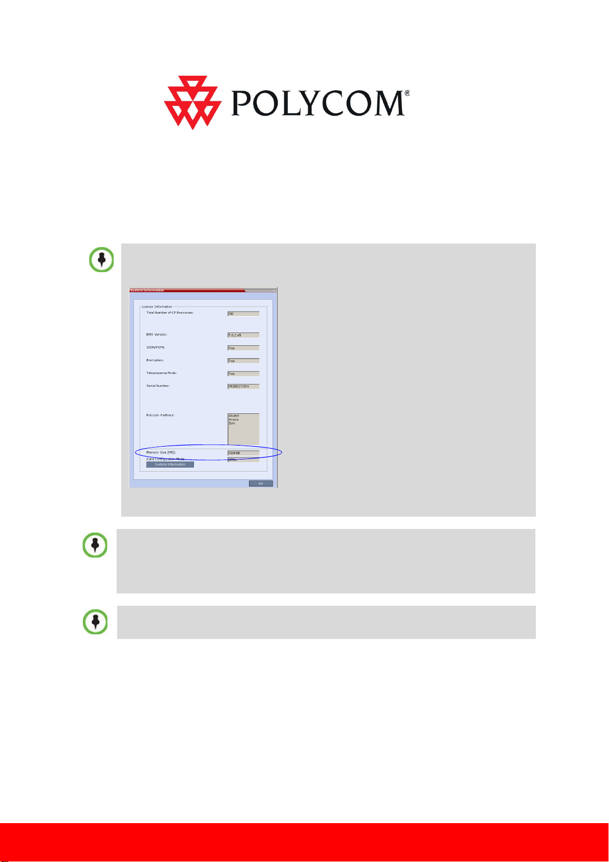
Version 7.0.x requires that the Control Unit memory size be at least 1024MB.
To check the RMX Memory size, in the RMX Web Client/RMX Manager go to Administration >
System Information.
If the control unit Memory size is 512MB, DO NOT perform the upgrade procedure and
contact Polycom support.
• The MPMx requires software version 7.0.x installed. First complete the version 7.0.x upgrade
procedure based on this document, then install the MPMx card/cards.
• RMX 4000 - when upgrading from MPM+ to MPMx cards, on the RTM-IP 4000 card, all
connections require Ferrite cables.
• If the upgrade process fails, please contact Polycom support.
To maximize conferencing performance, especially in high bit rate call environments, a 1Gb
connection is recommended.
Upgrading the RMX with MPM/MPM+ to MPMx cards involves the following processes:
• Process 1: Obtaining the License Key
• Process 2: Upgrading to Version 7.0.x
www.polycom.com
1
Page 2
Process 1: Obtaining the License Key
Version 7.0.x requires Product Registration and a new Product Activation Key. For more information, see
RMX 1500/2000/4000 Getting Started Guide, Chapter 2, ”Procedure 1: First-time Power-up” on page 2-18.
Based on your order and chassis information you have provided, you may require a new RMX 2000
D-type chassis with the MPMx card(s). The new RMX 2000 chassis is issued with an identical Chassis
Serial Number. Version 7.0.x and MPMx card(s) require a new Product Activation Key.
Process 2: Upgrading to Version 7.0.x (Latest Version)
You are required to first upgrade your MCU software to version 7.0.x. Start the software upgrade as
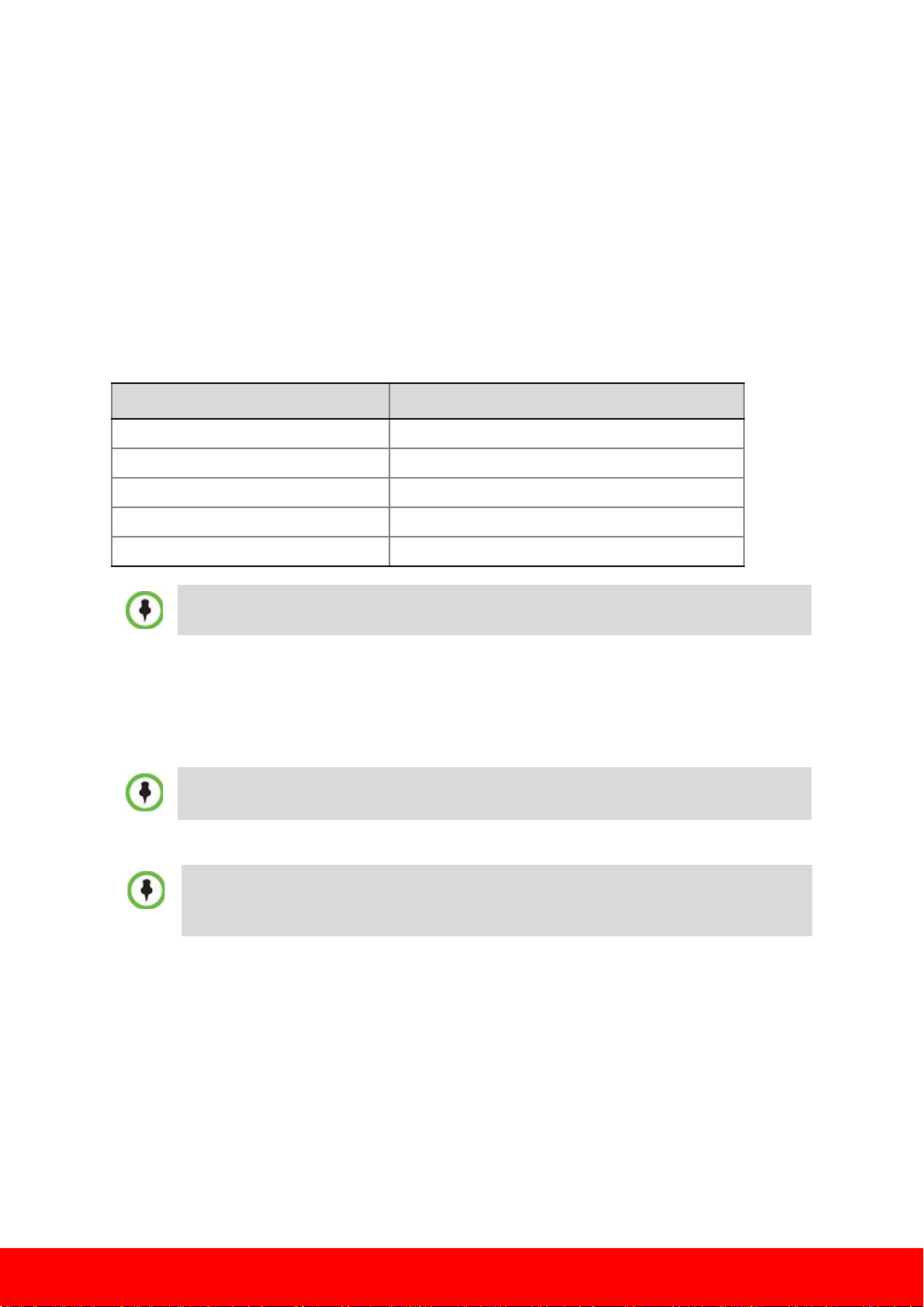
specified in the following table:
Current Installed Version Step(s) Required
2.x / 3.x 1,2,3,6*
4.x/4.x.x/5.x/5.x.x 2,3,6*
5.0.2 3,6*
6.x/6.0.x 4,6*
7.x/7.0.x 5
* Step 6 is applicable only for customers with RMX 2000 A/B/C-type chassis.
Step 1- Upgrading MCU Software from Version 2.x/3.x to Version 4.1.1
The upgrade procedure requires that you download and install version 4.1.1.
To upgrade from Version 2.x to Version 7.0.x, you must first upgrade to version 4.1.1, then upgrade
to version 5.0.2 and then upgrade to version 7.0.x. If after the installation of version 4.1.1 the MCU
reset fails, turn the system power off and on again.
The software upgrade procedure takes approximately 30 minutes to complete.
Do not interrupt the upgrade process in any way.
During the upgrade procedure, the MCU active alarms list indicates that the MCU is in the process
of upgrading the software. Y ou can start working with the RMX when the Active Alarm indication is
removed from the list.
1 Download the Version 4.1.1 software from the Polycom Resource Center web site.
2 Obtain the Version 4.1.1 Product Activation Key from the Polycom Resource Center web site. For more
information, see the RMX Getting Stated Guide, "Procedure 1: First-time Power-up” procedure on
page2-18.
3 Backup the configuration file. For more information, see the RMX 1500/2000/4000 Administrator’s
Guide, "Software Management” procedure on page18-98.
4 Install MCU Software Version 4.1.1
On the RMX® 2000 menu, click Administration> Software Management > Software Download.
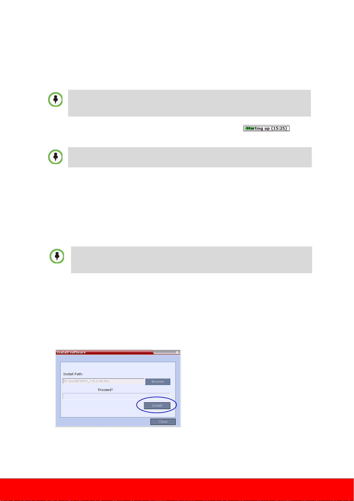
5 Browse to the Install Path, selecting the Version 4.1.1xx.bin file in the folder where Version 4.1.1 is
saved and click Install.
2
Page 3
At the end of the installation process the system displays an indication that the software was
Version
Number
successfully downloaded and that a new activation key is required.
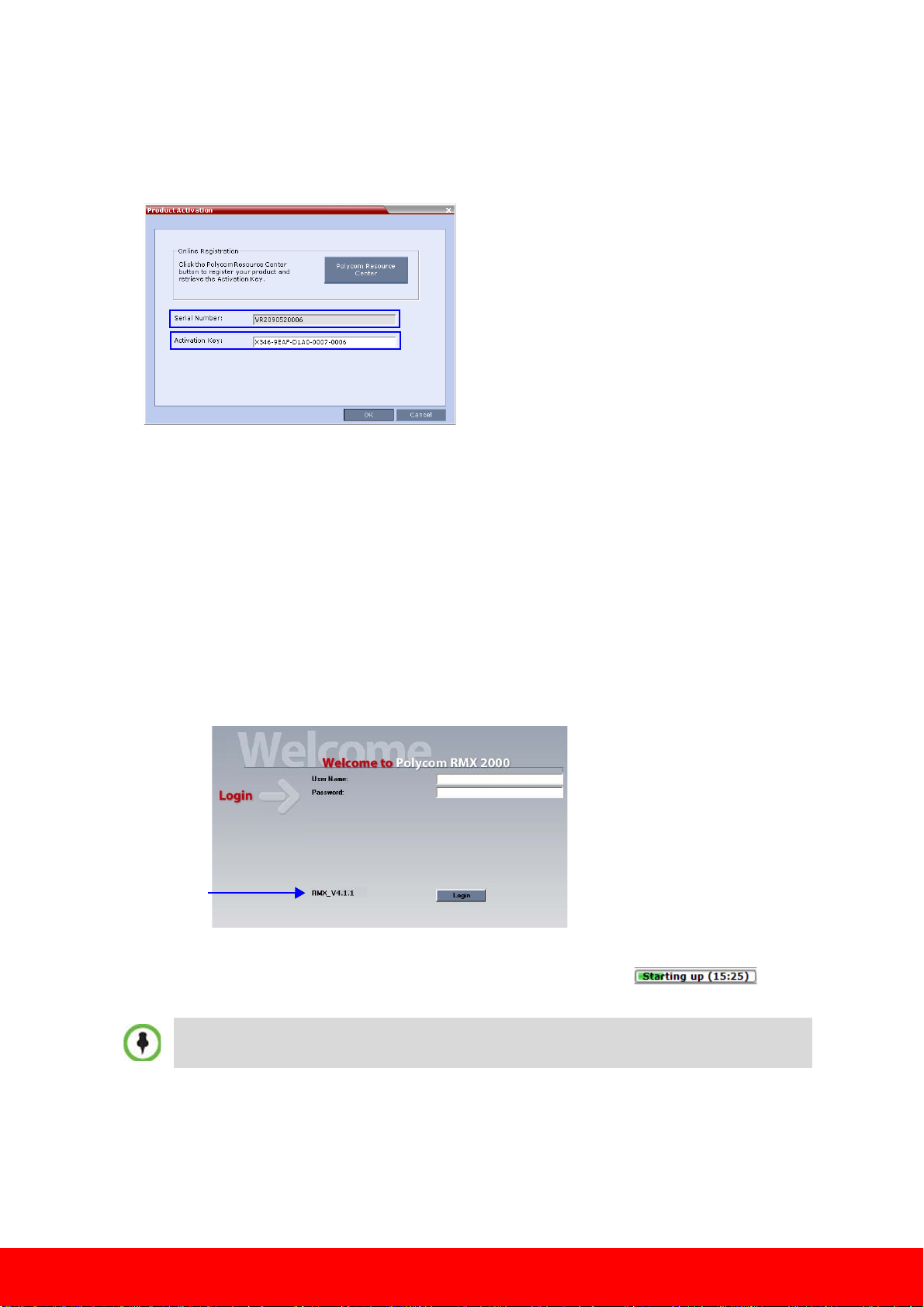
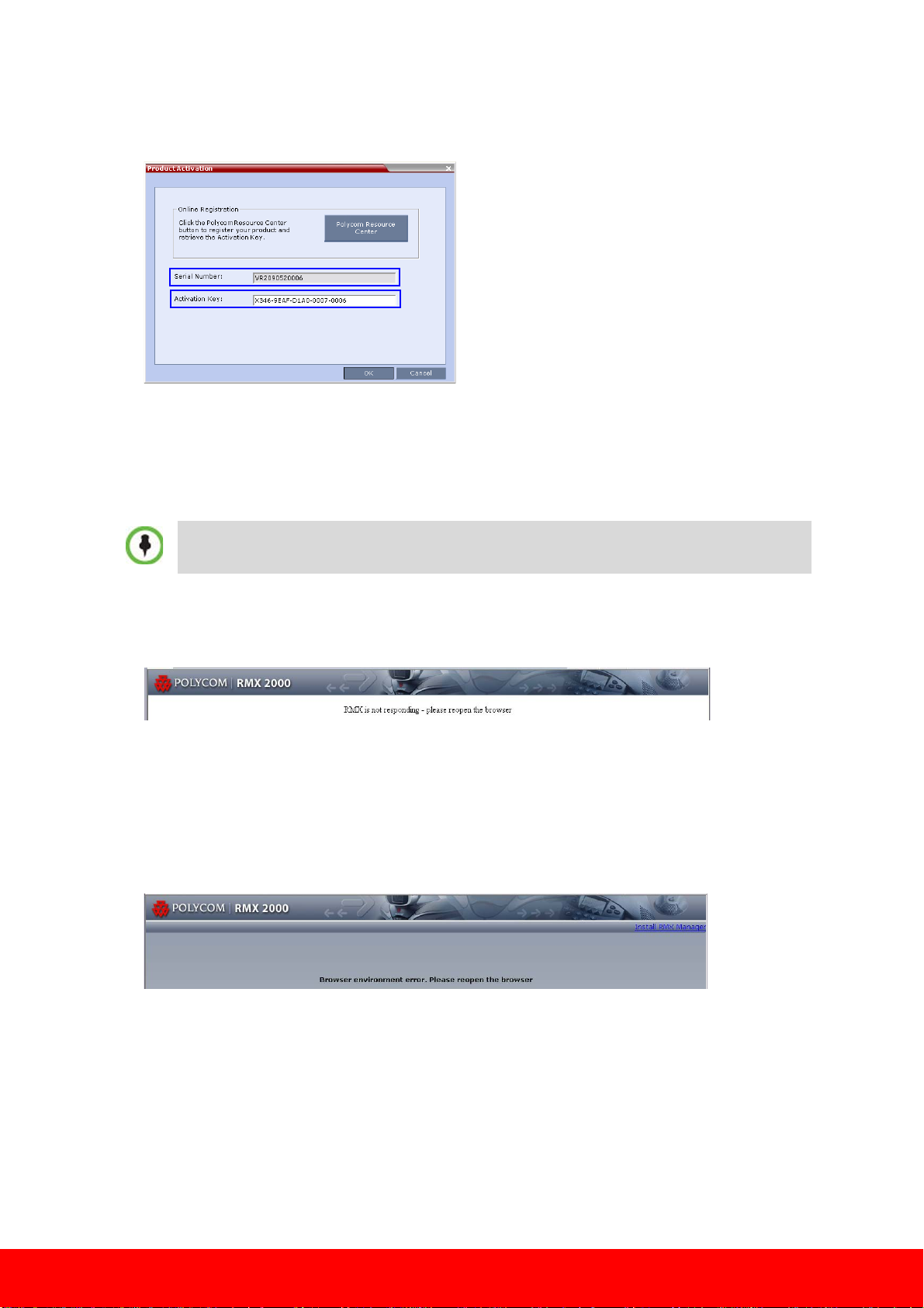
6 On the RMX menu, click Setup > Product Activation.
The Product Activation dialog box is displayed with the serial number field completed.
7 In the Activation Key field, enter or paste the Product Activation Key obtained earlier and click the
OK button.
At the end of the Product Activation process the system displays an indication that the Product
Activation Key was successfully installed.
8 Click the OK button.
9 When prompted whether to reset the MCU, click Yes to reset the MCU.
The upgrade procedure may take up to 30 minutes during which time an Active Alarm - System
Upgrade is displayed.
The RMX resets itself during the upgrade process and connection to the RMX Web Client may be
lost. If the workstation is logged in to the RMX Web Client during the resets, the MCU State
indicator at the bottom right corner of the RMX Web Client screen indicates STARTUP.
10 After 30 minutes, close and re-open the browser and connect to the RMX.
The version number in the Welcome screen has changed to 4.1.1
11 In the RMX Web Client – Welcome screen, enter your User Name and Password and click Login.
In the Main Screen an MCU State indicator displays a progress indicator
showing the time remaining until the system start-up is complete.
After software installation and MCU restart, the RMX 2000 powers-up in MPM Card Configuration
Mode.
12 The upgrade to Version 4.1.1 is complete. Now proceed with the upgrade from Version 4.x to
Version 5.0.2. For more information, see “Step 2 - Upgrading from 4.x/5.x/5.0.x to Version 5.0.2” on
page 4.
3
Page 4
Step 2 - Upgrading from 4.x/5.x/5.0.x to Version 5.0.2
• When upgrading from version 4.x or 5.x/5.0.x to version 7.0.x, you must first upgrade to
version 5.0.2. Do not perform any other intermediate upgrade.
• If Windows7™ is installed on the workstation, Protected Mode must be disabled before
downloading the Version 5.0.2 software to the workstation.
1 Download the required software Version 5.0.2 from the Polycom Resource Center web site.
2 Obtain the Version 5.0.2 Product Activation Key from the Polycom Resource Center web site. For more
information, see the RMX Getting Stated Guide, Chapter 2, ”Procedure 1: First-time Power-up” on
page 2-18.
3 Backup the configuration file. For more information, see the RMX Administrator’s Guide, "Software
Management” procedure on page18-98.
4 Install MCU Software Version 5.0.2.
On the RMX 2000 menu, click Administration> Software Management > Software Download.
5 Browse to the Install Path, selecting the Version 5.0.2.bin file in the folder where Version 5.0.2 is
saved and click Install.
At the end of the installation process the system displays an indication that the software was
successfully downloaded and that a new activation key is required.
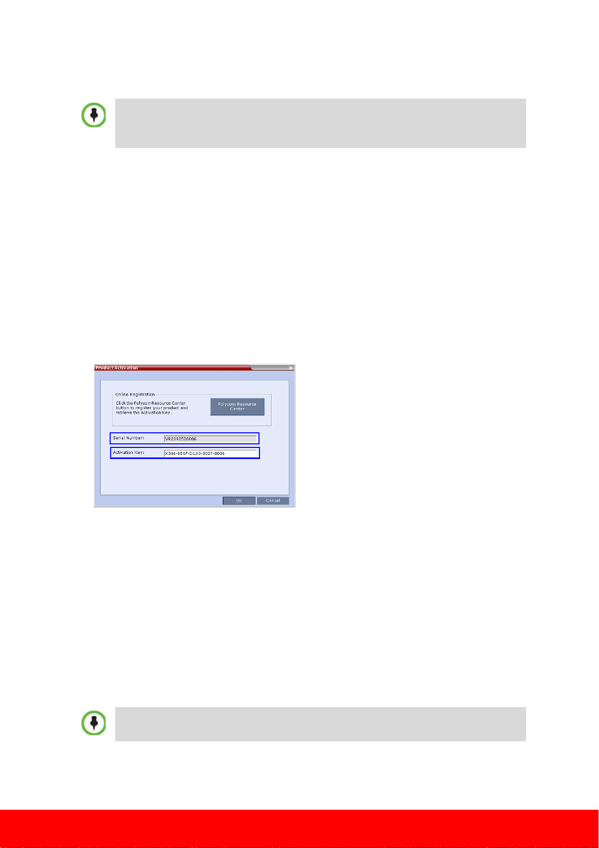
6 On the RMX menu, click Setup > Product Activation.
The Product Activation dialog box is displayed with the serial number field completed.
7 In the Activation Key field, enter or paste the Product Activation Key obtained earlier and click the
OK button.
At the end of the Product Activation process the system displays an indication that the Product
Activation Key was successfully installed.
8 Click the OK button.
9 When prompted whether to reset the MCU, click Yes to reset the MCU.
At the end of the installation process the system displays an indication that the software was
successfully downloaded.
The upgrade procedure takes about 30 minutes during which time an Active Alarm - System
Upgrade is displayed.
The RMX resets itself during the upgrade process and connection to the RMX Web Client may be
lost. If the workstation is logged in to the RMX Web Client during the resets, the MCU State
indicator at the bottom right corner of the
Sometimes when upgrading from version 4.x to version 5.0.x the reset process fails. In such a case,
you can try to connect to the MCU via the Shelf Management and reset the MCU from the Hardware
Monitor or you can “hard” reset the MCU by turning the Power off and on again.
RMX Web Client screen indicates STARTUP.
4
Page 5
10 After about 30 minutes, close and reopen the browser and connect to the RMX.
If the browser was not closed and reopened, the following error message is displayed: “Browser
environment error. Please reopen the browser”.
The version number in the Welcome screen has changed to 5.0.2.
11 In the RMX Web Client – Welcome screen, enter your Username and Password and click Login.
If upgrading from version 4.x, after software installation, the MCU is in the last Card Configuration
Mode that was set for the system before the software upgrade. For more information on the Card
Configuration Modes, see the RMX 2000 Hardware Guide, "MPM/MPM+ and MPMx Media Cards”
procedure on page 1-16.
In the Main Screen an MCU State indicator displays a progress indicator
showing the time remaining until the system start-up is complete.
If the default POLYCOM user is defined in the RMX Web Client, an Active Alarm is created and the
MCU status changes to MAJOR until the POLYCOM User is renamed or a new Administrator User is
created and the default User is deleted.
12 The upgrade to Version 5.0.2 is complete. Now proceed with the upgrade from Version 5.0.2 to
Version 7.0.x. For more information, see “Step 3 - Upgrading from Version 5.0.2 to Version 7.0.x
(Latest Version)” on page 5.
Step 3 - Upgrading from Version 5.0.2 to Version 7.0.x (Latest Version)
1 Download the required software Version 7.0.x from the Polycom Resource Center web site.
If Windows7™ is installed on the workstation, Protected Mode must be disabled before
downloading the Version 7.0.x software to the workstation.
For more information see, Version 7.0.x RMX Release Notes, “Windows 7™ Security Settings” on
page 9.
2 Obtain the Version 7.0.x Product Activation Key from the Polycom Resource Center web site. For more
information, refer to the RMX Software Licence document you received with your shipment.
3 Backup the configuration file. For more information, see the RMX 1500/2000/4000 Administrator’s
Guide, "Software Management” procedure on page18-98.
4 Install MCU Software Version 7.
On the RMX 2000 menu, click Administration > Software Management > Software Download.
5 Browse to the Install Path, selecting the Version 7.0.x.bin file in the folder where version 7.0.x is
saved and click Install.
0.x.
At the end of the installation process the Install Software dialog box indicates that the installed
software is being checked. The system then displays an indication that the software was
successfully downloaded and that a new activation key is required.
5
Page 6
6 On the RMX 2000 menu, click Setup>Product Activation.
The Product Activation dialog box is displayed with the serial number field completed.
7 In the Activation Key field, enter or paste the Product Activation Key obtained earlier and click the
OK button.
At the end of the Product Activation process the system displays an indication that the Product
Activation Key was successfully installed.
8 When prompted whether to reset the RMX, click Yes to reset the RMX.
Sometimes when upgrading from version 5.0.2 to version 7.0.x the reset process fails. In such a
case, you can try to connect to the MCU via the Shelf Management and reset the MCU from the
Hardware Monitor or you can “hard” reset the MCU by turning the Power off and on again.
9 When prompted to wait while the RMX resets, click OK.
The upgrade procedure takes approximately 30 minutes.
Connection to the RMX is terminated and you are prompted to reopen the browser.
10 After approximately 30 minutes close and reopen the browser.
11 Enter the IP address of the RMX Control Unit in the browser’s address line and press Enter to
reconnect to RMX.
The browser displays a message indicating that it cannot display the requested page.
12 Refresh the browser periodically until connection to the RMX is established and the Login screen is
displayed.
You may receive a message stating Browser environment error. Please reopen the browser.
13 Enter the IP address of the RMX Control Unit in the browser’s address line and press Enter to
reconnect to RMX.
6
Page 7

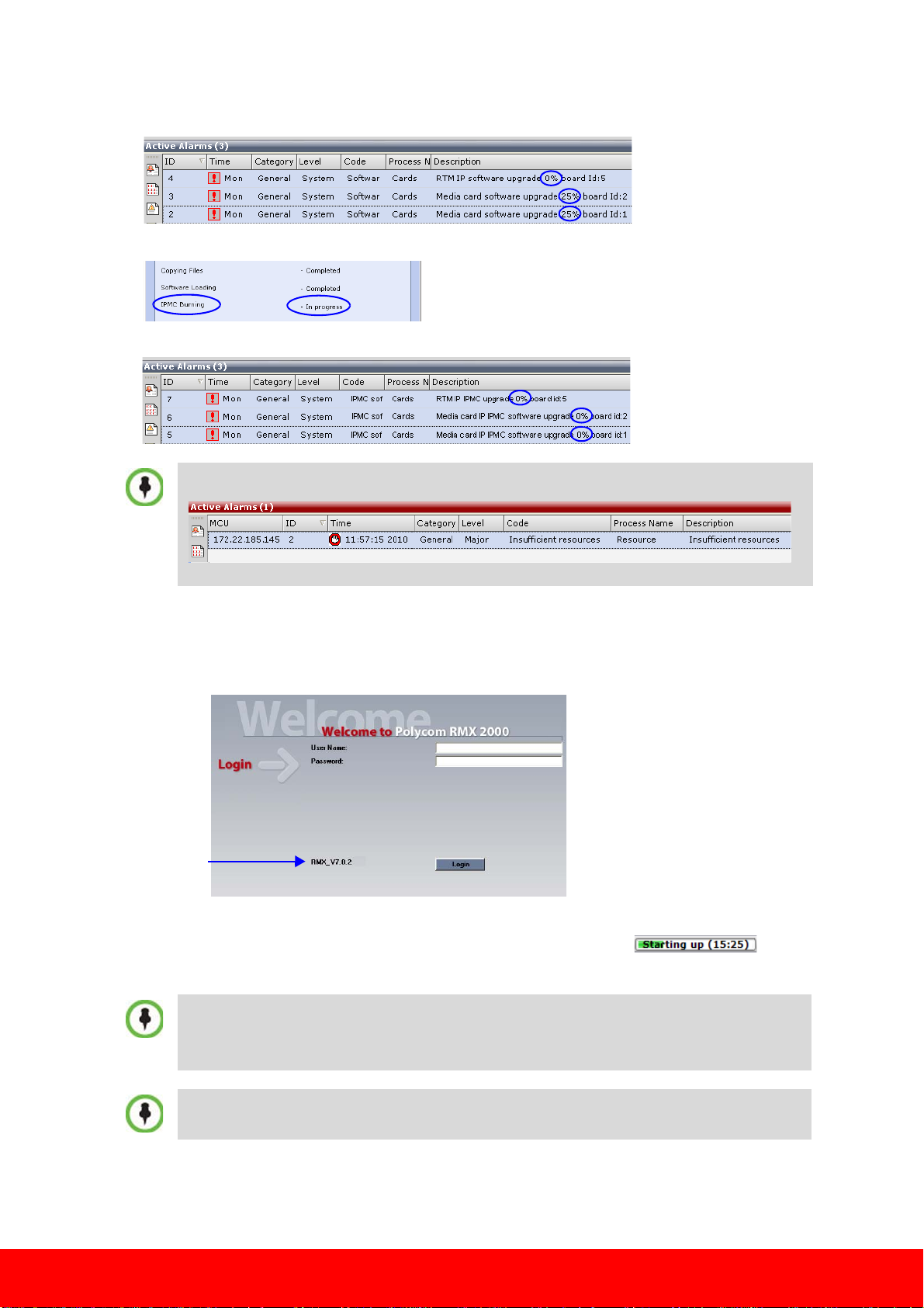
The Login screen is displayed. The version number has changed to 7.0.x.
Version
Number
14 In the RMX Web Client – Welcome screen, enter your Username and Password and click Login.
In the Main Screen an MCU State indicator displays a progress indicator
showing the time remaining until the system start-up is complete
If the default POLYCOM user is defined in the RMX Web Client, an Active Alarm is created and the
MCU status changes to MAJOR until a new Administrator user is created and the default user is
deleted.
RMX 2000 with A/B/C-type Chassis users proceed with “Step 5 - Upgrading from Version 7.0/7.0.1
to Version 7.0.x (Latest Version)” on page 12.
15 To use the new features such as Operator Assistance and Gateway Sessions the IVR Services must be
updated. For more details, see Version 7.0.x Release Notes.
16 Prior to removing an MPM/MPM+ card the captive screws must be unscrewed and the ejector
levers must be opened to initiate a “power down” on the card.
17 Carefully slide the MPM/MPM+ card out through the front panel.
18 On the MPMx card to be installed, move the ejector levers to their fully open position. For more
information, see “Using the Modified PMC Compatible Ejector Lever” on page 15.
19 Slide in the MPMx card and tighten the captive screws.
20 A message appears indicating that the MCU is currently in MPM/MPM+ Card Configuration
Mode and the MPMx card is disabled.
21 Reset the MCU to switch to the MPMx Configuration Mode.
22 The card startup procedure is complete when the MPMx card successfully completes startup and
the green RDY (Ready) LED remains lit.
7
Page 8

Step 4 - Upgrading from Version 6.0/6.0.1/6.0.x to Version 7.0.x (Latest Version)
A.) Intermediate Upgrade from Version 6.0/6.0.1 to Version
6.0.2
1 Download the Version 6.0.2 software from the Polycom Resource Center web site.
If Windows7™ is installed on the workstation, Protected Mode must be disabled before downloading
the Version 6.0.2 software to the workstation.
For more information see the Release Notes version 7.0.x, “Windows 7™ Security Settings” on
page 11.
2 Backup the configuration file. For more information, see the RMX 1500/2000/4000 Administrator’s
Guide, "Software Management” procedure on page18-98.
3 Install MCU Software Version 6.0.2.
On the RMX menu, click Administration > Software Management > Software Download.
4 Browse to the Install Path, selecting the Version 6.0.2xx.bin file in the folder where Version 6.0.2 is
saved and click Install.
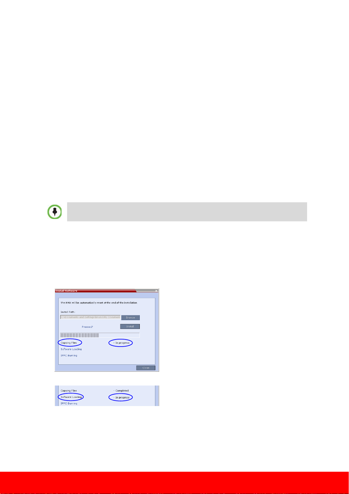
The Install Software information box that the file copy is In progress.
The Install Software information box indicates that Software Loading is in progress.
A series of Active Alarms are displayed indicating the progress of the upgrade process.
The Install Software information box indicates that IPMC Burning is in progress.
8
Page 9

A further series of Active Alarms are displayed indicating the progress of the upgrade process.
Version
Number
The upgrade procedure takes approximately 20 minutes.
When upgrading from version 6.0.1, if after 20 minutes the system remains in the Loading Software
stage:
and sometimes the following Active Alarm is displayed:
Close the Install Software window, access the Hardware Monitor and Reset the RMX.
After reset, the upgrade process continues as described below.
Connection to the RMX is terminated and you are prompted to reopen the browser.
5 After approximately 5 minutes close and reopen the browser.
6 Enter the IP address of the RMX Control Unit in the browser’s address line and press Enter to
reconnect to RMX.
The Login screen is displayed. The version number has changed to 6.0.2.
7 In the RMX Web Client – Welcome screen, enter your User Name and Password and click Login.
In the Main Screen an MCU State indicator displays a progress indicator
showing the time remaining until the system start-up is complete.
9
Page 10

B.) Upgrading from Version 6.0.2 to Version 7.0.2
1 Download the required software Version 7.0.x from the Polycom Resource Center web site.
2 Obtain the Version 7.0.x Product Activation Key from the Polycom Resource Center web site. For more
information, refer to the RMX Software License document you received with your shipment.
3 Backup the configuration file. For more information, see the RMX Administrator’s Guide, "Software
Management” procedure on page18-98.
4 Install MCU Software Version 7.0.x.
On the RMX 2000 menu, click Administration> Software Management > Software Download.
5 Browse to the Install Path, selecting the Version 7.0.x.bin file in the folder where Version 7.0.x is
saved and click Install.
The Install Software information box that the file copy is In progress.
At the end of the installation process the system displays an indication that the software copying
procedure is Completed and that a new Activation Key is required.
6 Click the OK button.
7 On the RMX 2000 menu, click Setup>Product Activation.
The Product Activation dialog box is displayed with the serial number field completed.
8 In the Activation Key field, enter or paste the Product Activation Key obtained earlier and click the
OK button.
At the end of the Product Activation process the system displays an indication that the Product
Activation Key was successfully installed.
9 Click the OK button.
The Install Software information box indicates that Software Loading is in progress.
10
Page 11
A series of Active Alarms are displayed indicating the progress of the upgrade process.
Version
Number
The Install Software information box indicates that IPMC Burning is in progress.
A further series of Active Alarms are displayed indicating the progress of the upgrade process.
Sometimes, when updating the Version 7.0.x license key, the system displays the following active
alarm:
Ignore this Active Alarm and complete this installation procedure.
10 After about 30 minutes, close and reopen the browser and connect to the RMX.
If the browser was not closed and reopened, the following error message is displayed: “Browser
environment error. Please reopen the browser”.
The version number in the Welcome screen has changed to 7.0.2.
11 In the RMX Web Client – Welcome screen, enter your User Name and Password and click Login.
In the Main Screen an MCU State indicator displays a progress indicator
showing the time remaining until the system start-up is complete.
• If the default POLYCOM user is defined in the RMX Web Client, an Active Alarm is created and
the MCU status changes to MAJOR until a new Administrator user is created and the default
user is deleted.
• If the upgrade process fails, please contact Polycom support.
RMX 2000 with A/B/C-type Chassis users proceed with “Step 5 - Upgrading from Version 7.0/7.0.1
to Version 7.0.x (Latest Version)”
on page 12.
11
Page 12
12 To use the new features such as Operator Assistance and Gateway Sessions the IVR Services must be
updated. For more details, see Version 7.0.x Release Notes, “Additional/Optional System Updates
After Upgrading” on page 15.
13 Prior to removing an MPM/MPM+ card the captive screws must be unscrewed and the ejector
levers must be opened to initiate a “power down” on the card.
14 Carefully slide the MPM/MPM+ card out through the front panel.
15 On the MPMx card to be installed, move the ejector levers to their fully open position. For more
information, see “Using the Modified PMC Compatible Ejector Lever” on page 15.
16 Slide in the MPMx card and tighten the captive screws.
17 A message appears indicating that the MCU is currently in MPM/MPM+ Card Configuration
Mode and the MPMx card is disabled.
18 Reset the MCU to switch to the MPMx Configuration Mode.
The card startup procedure is complete when the MPMx card successfully completes startup and
the green RDY (Ready) LED remains lit.
Step 5 - Upgrading from Version 7.0/7.0.1 to Version 7.0.x (Latest Version)
1 Download the required software Version 7.0.x from the Polycom Resource Center web site.
If Windows7™ is installed on the workstation, Protected Mode must be disabled before downloading
the Version 7.0.2 software to the workstation.
2 Backup the configuration file. For more information, see the RMX Administrator’s Guide, "Software
Management” procedure on page18-98.
3 Install MCU Software Version 7.0.x.
On the RMX 2000 menu, click Administration> Software Management > Software Download.
4 Browse to the Install Path, selecting the Version 7.0.2.bin file in the folder where Version 7.0.2 is
saved and click Install.
The Install Software information box indicates that the file Copying files is In progress.
The Install Software information box indicates that Software Loading is in progress.
12
Page 13

A series of Active Alarms are displayed indicating the progress of the upgrade process.
Version
Number
The Install Software information box indicates that IPMC Burning is in progress.
A further series of Active Alarms are displayed indicating the progress of the upgrade process.
Sometimes, when updating the Version 7.0.x license key, the system displays the following active
alarm:
Ignore this Active Alarm and complete this installation procedure.
The upgrade procedure takes approximately 20 minutes.
Connection to the RMX is terminated and you are prompted to reopen the browser.
5 Approximately 5 minutes after receiving this message, close and reopen the browser.
6 Enter the IP address of the RMX Control Unit in the browser’s address line and press Enter to
reconnect to RMX.
The browser displays a message indicating that it cannot display the requested page.
The version number in the Welcome screen has changed to 7.0.x.
7 In the RMX Web Client – Welcome screen, enter your User Name and Password and click Login.
13
Page 14

In the Main Screen an MCU State indicator displays a progress indicator
showing the time remaining until the system start-up is complete.
• If the default POLYCOM user is defined in the RMX Web Client, an Active Alarm is created and
the MCU status changes to MAJOR until a new Administrator user is created and the default user
is deleted.
• If the upgrade process fails, please contact Polycom support.
8 To use the new features such as Operator Assistance and Gateway Sessions the IVR Services must be
updated. For more details, see “Additional/Optional System Updates After Upgrading” on page 15 in
the RMX Release Notes.
Step 6 - Upgrading RMX 2000 A/B/C-type Chassis Users
Step 6a. Removing MCU Components from the Existing Chassis and Removing the Chassis from the Rack
1 Power down the MCU.
2 Disconnect the following cables from the back panel:
— Power cable
— LAN cable from LAN 2 port
— Optional - if installed. E1/T1 Cables from PRI ports
3 Remove the following components:
On each component captive screws must be loosened and ejector lever or levers must be opened.
Care must be taken opening or closing the All Metal Ejector Lever or Modified PMC Compatible
Ejector Lever as described in “Using the Ejector Lever” below. Ensure that power to the RMX is
turned OFF (O) before performing the procedures described below.
— Remove the CNTL unit from the front of the RMX (see page 15).
— Remove the Power Supply drawer from the front of the RMX (see page 16).
— Remove RTM IP card from the rear of the RMX (see page 16).
— Optional - if installed. Remove the RTM ISDN card from the rear of the RMX (see page 16).
— Optional. Remove the MPM card from the front of the RMX.
4 Remove the RMX unit from the rack (see page 17).
Using the Ejector Lever
Using the All Metal Ejector Lever
This ejector lever can be moved to 3 positions:
• Closed - The ejector levers are fully retracted and pushed up against the card’s panel.
• Partially Open - For card powering down mode. Partially open the ejector lever(s) until the blue
HS LEDs on the card and the Control Unit start flashing. When the HS LED remains lit the card is
in a powered down mode and you can remove the card.
Warning!
Once the removal sequence is initiated and the HS LED flashes, the process cannot be terminated.
• Fully Open - The card is released from the MCU housing.
14
Page 15
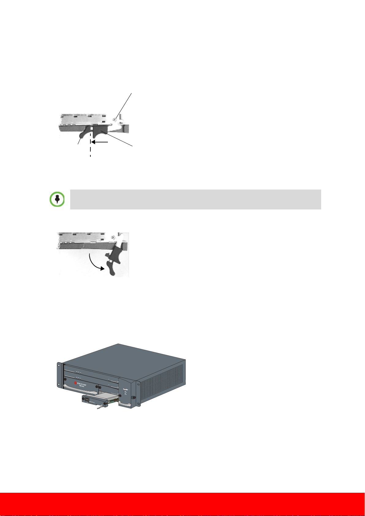
Using the Modified PMC Compatible Ejector Lever
Handle
Unlocking the Lock Catch - With your index finger holding
the “handle” and your thumb shifting the catch to left, gently
pull the handle away from the chassis until the lever is “fully
open”
Closing the Lever - Make sure that the lever is in an open
position and push card close to the chassis till the lever
engages. With your index finger holding the “handle” and
your thumb holding the catch fully to left, push the card
against the chassis whilst closing the lever. Release Lock
Catch and allow it to “click” into place, ensuring that the
card is properly placed against the chassis.
Lever Fully Open - Pull the lever handle(s) to a
fully open position (approx. 70 degrees), as
shown here
This ejector lever can be moved to 3 positions:
• Closed/Locked - Ejector lever(s) are gently pushed up against the card’s panel and is locked.
Ensure that the lock catch is in the standard closed position (shifted to the right as shown below)
• Partially Open - For card powering down mode. Partially open the ejector lever(s) until the blue
HS LEDs on the card and the Control Unit start flashing. When the HS LED remains lit the card is
in a powered down mode and you can remove the card.
Warning!
Once the removal sequence is initiated and the HS led flashes, the process cannot be terminated.
• Fully Open - In this position the card is released from the MCU housing and can be removed.
Removing the CPU (CNTL) Module
1 Unscrew the captive screws on the front panel of the RMX 2000 that secure the CNTL Module.
2 Use the ejector levers (see “Using the Ejector Lever” on page 14) to pull the
slot in the Backplane.
3 Carefully slide the
CNTL Module out through the front panel.
CNTL Module out of its
15
Page 16

Removing the Power Supply Drawer
1 Unscrew the captive screws on the front panel of the RMX 2000 that secure the Power Supply.
2 Use the ejector levers (see “Using the Ejector Lever” on page 14) to pull the Power Supply Module
out of its slot in the Backplane.
3 Carefully slide the Power Supply Module out through the front panel.
Removing the RTM IP Card
1 Unscrew the captive screws on the rear panel of the RMX 2000 that secure the RTM IP card.
2 Use the ejector levers (see “Using the Ejector Lever” on page 14) to pull the RTM IP card out of its
slot in the Backplane.
3 Carefully slide the RTM IP card out through the rear panel.
Optional. Removing the RTM ISDN Card
1 Unscrew the captive screws on the rear panel of the RMX 2000 that secure the RTM ISDN card.
2 Use the ejector levers (see “Using the Ejector Lever” on page 14) to pull the RTM ISDN card out of
its slot in the Backplane.
3 Carefully slide the RTM ISDN card out through the rear panel.
16
Page 17
Removing the RMX from the Rack
The RMX® 2000 is installed in a rack using rack brackets or a shelf. Removing the MCU from the rack
is done in the same way for both installation methods:
• Unscrew the four captive screws in the RMX’s front mounting brackets that fasten the RMX to the
rack. Remove the RMX from the rack.
Step 6b. - Installing MCU Components in the New RMX 2000 D-type Chassis and Mounting it in the Rack
The new chassis is delivered with the fan drawer and MPMx card installed.
1 Unpack the new chassis and place it on a flat, stable surface.
2 Install the following components in the new chassis:
— Power Supply drawer (see “Installing the Power Supply Drawer” on page 18)
— CNTL unit (see “Installing the CPU (CNTL) Module” on page 18)
— RTM IP card (see “Installing the RTM IP Card” on page 18)
— Optional. RTM ISDN card (see “Installing the RTM ISDN Card” on page 19)
On each component the card pins must be aligned and ejector lever or levers must be pushed back
into their housing and lock(ed) as described in the “Using the Ejector Lever” on page 14. Ensure also
that each captive screw is fastened properly.
3 Mount the RMX 2000 D-type chassis with all its components in the rack (see “Mounting the
Assembled RMX 2000 D-type Chassis in the Rack” on page 19).
4 Connect all the required cables (see “Connecting Cables” on page 19).
5 Turn on the MCU and login.
Note: On all cards, if during the startup phase the blue HS LED remains lit, please make sure that
the card is properly seated in the slot. A lit HS LED indicates that the card is in a powered down
mode. If this problem persists, contact your next level of support.
A message appears indicating that the MCU is currently in MPM Card Configuration Mode and
the MPMx card is disabled.
6 Reset the MCU to switch the RMX 2000 to the MPMx Configuration Mode.
7 The card startup procedure is complete when the MPMx card successfully completes startup and
the green RDY (Ready) LED remains lit.
17
Page 18
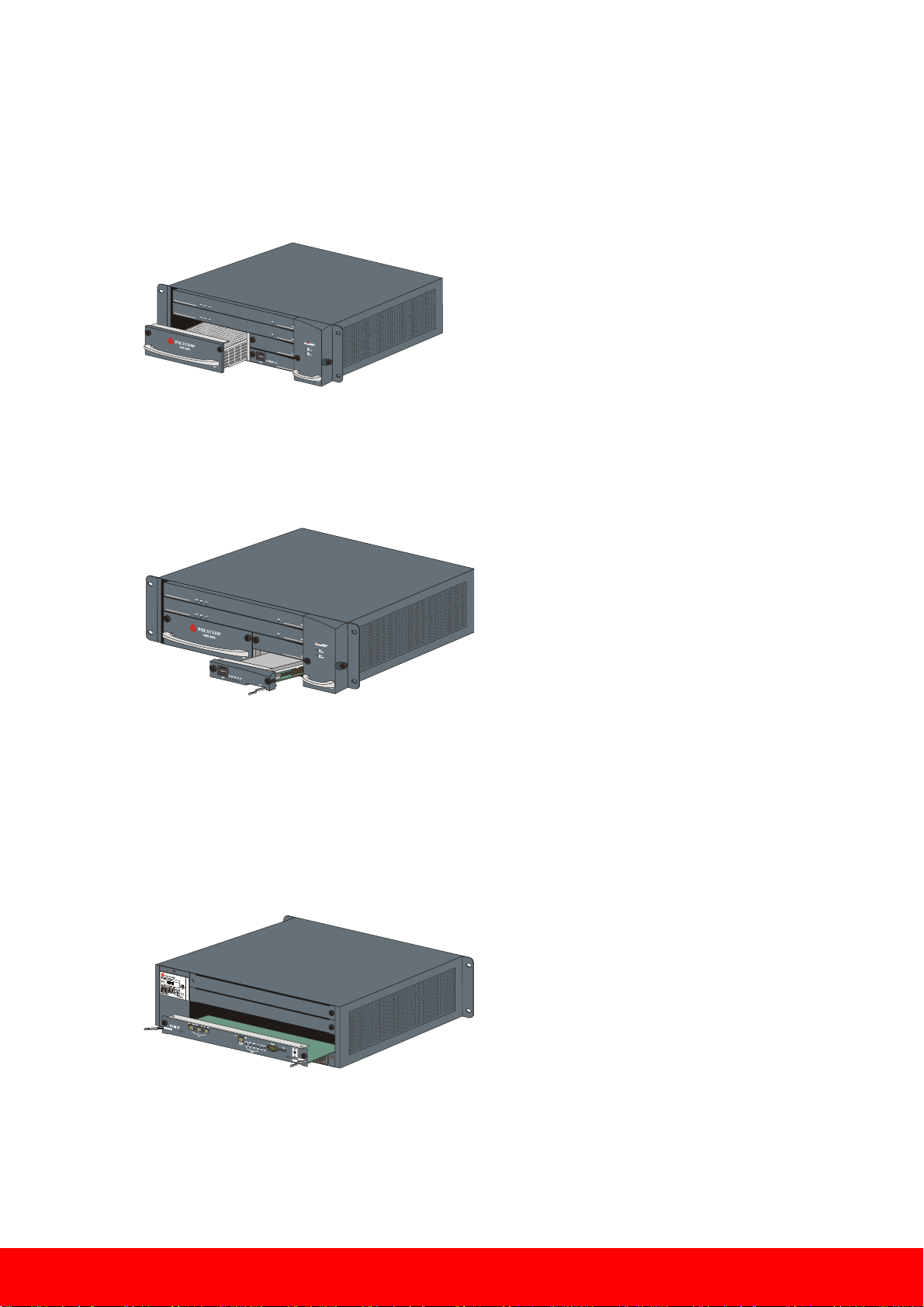
Installing the Power Supply Drawer
1 Slide in the Power Supply Module.
2 Push the Power Supply Module firmly into the Backplane, making sure it is properly seated in its
slot. Ensure that the ejector levers are fully retracted into their housings (see “Using the Ejector
Lever” on page 14).
3 Tighten the captive screws on the front panel of the RMX that secure the Power Supply Module.
Installing the CPU (CNTL) Module
1 Slide in the CNTL Module. Push the CNTL Module firmly into the Backplane, making sure it is
properly seated in its slot.
2 Tighten the captive screws on the front panel of the RMX that secure the
CNTL Module.
Installing the RTM IP Card
1 Slide in the replacement RTM IP card.
2 Push the RTM IP card firmly into the Backplane, making sure it is properly seated in its slot.
Ensure that the ejector levers are fully retracted into their housings (see “Using the Ejector Lever”
on page 14).
3 Tighten the captive screws on the rear panel of the RMX that secure the RTM IP card.
18
Page 19

Installing the RTM ISDN Card
Ejector Lever
Captive Screw
Power
Cable
E1/T1 PRI Connection
LAN 2 Connection
1 Slide in the replacement RTM ISDN card in the slot opposite to where an MPM+ card is seated.
2 Push the RTM ISDN card firmly into the Backplane, making sure it is properly seated in its slot.
3 Ensure that the ejector levers are fully retracted into their housings (see “Using the Ejector Lever”
on page 14).
4 Tighten the captive screws on the rear panel of the RMX 2000 that secure the RTM ISDN card.
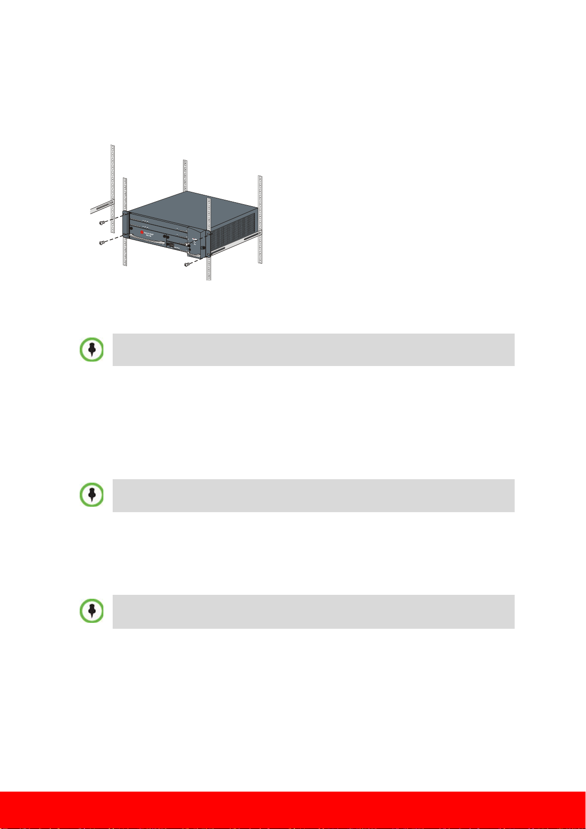
Mounting the Assembled RMX 2000 D-type Chassis in the Rack
• Using rack brackets – Mount the RMX on top of the rack brackets or on the shelf. Fasten the RMX
to the rack with screws through the four holes in the RMX’s front mounting brackets.
Connecting Cables
Do not remove the protective caps from LAN1, LAN3 and ShMG ports.
Connect the following cables to the back panel:
•Power cable
•LAN cable to LAN 2 Port
• Optional. E1/T1 Cables to PRI Ports
19
Page 20

Please be aware that the old RMX 2000 chassis and MPM/MPM+ board(s)
cannot be disposed of with household waste. Instead, it is your responsibility to
dispose of outdated equipment by handing it over to a designated collection point
for the recycling of electronic equipment. The collection and recycling of obsolete
equipment will help conserve natural resources and protect the environment.
For more information about recycling and where you can drop off your
equipment, please contact your local city office, your waste disposal service or
your next level of support where you purchased the product.
20
DOC2568C
 Loading...