

Page 1

RMX 2000
Getting Started Guide
Version 1.1
Page 2

Copyright © 2007 Polycom, Inc.
All Rights Reserved
Catalog No. DOC2159A
Version 1.1
Proprietary and Confidential
The information contained herein is the sole intellectual property of Polycom, Inc. No distribution, reproduction or unauthorized
use of these materials is permitted without the expressed written consent of Polycom, Inc. Information contained herein is subject
to change without notice and does not represent commitment of any type on the part of Polycom, Inc. Polycom and Accord are
registered trademarks of Polycom, Inc.
Notice
While reasonable effort was made to ensure that the information in this document was complete and accurate at the time of
printing, Polycom, Inc., cannot assume responsibility for any errors. Changes and/or corrections to the information contained in
this document may be incorporated into future issues.
Page 3

Regulatory Notices
United States Federal Communication
Commission (FCC)
Part 15: Class A Statement. This equipment has
been tested and found to comply with the limits for a
Class A digital device, pursuant to Part 15 of the FCC
Rules. Test limits are designed to provide reasonable
protection against harmful interference when the
equipment is operated in a commercial environment.
This equipment generates, uses and can radiate
radio-frequency energy and, if not installed and used
in accordance with the instruction manuals, may
cause harmful interference to radio communications.
Operation of this equipment in a residential area is
likely to cause harmful interference, in which case the
user will be required to correct the interference at his
or her own expense.
United States Safety Construction Details:
• Unit is intended for RESTRICTED ACCESS
LOCATION.
• Unit is to be installed in accordance with the
National Electrical Code.
• The branch circuit overcurrent protection shall
be rated 20 A for the AC system.
• This equipment has a maximum operating
ambient of 40°C, the ambient temperature in
the rack shall not exceed this temperature.
To eliminate the risk of battery explosion, the battery
should not be replaced by an incorrect type. Dispose
of used batteries according to their instructions.
CE Mark R&TTE Directive
Polycom Inc., declares that the Polycom RMX 2000 is
in conformity with the following relevant harmonized
standards:
EN 60950-1:2001
EN 55022: 1998+A1:2000+A2:2003 class A
EN 300 386 V1.3.3: 2005
Following the provisions of the Council Directive
1999/CE on radio and telecommunication terminal
equipment and the recognition of its conformity.
Canadian Department of Communications (EC)
This Class [A] digital apparatus complies with
Canadian ICES-003.
Notice: The Industry Canada label identifies certified
equipment. This certification means that the
equipment meets telecommunication network
protective, operational and safety requirements as
prescribed in the appropriate Terminal Equipment
Technical Requirements document(s). The
Department does not guarantee the equipment will
operate to the user's satisfaction.
Before installing this equipment, users should ensure
that it is permissible to be connected to the facilities
of the local telecommunications company. The
equipment must also be installed using an acceptable
method of connection. The customer should be
aware that compliance with the above conditions may
not prevent degradation of service in some situations.
Repairs to certified equipment malfunctions, may give
the telecommunications company causes to request
the user to disconnect the equipment.
Users should ensure for their own protection that the
electrical ground connections of the power utility,
telephone lines and internal metallic water pipe
system, if present, are connected together. This
precaution may be particularly important in rural
areas.
Caution: Users should not attempt to make such
connections themselves, but should contact the
appropriate electric inspection authority, or
electrician, as appropriate.
Page 4

Regulatory Notices
Chinese Communication Certificate
Page 5

Polycom RMX 2000 Getting Started Guide
Table of Contents
System Overview . . . . . . . . . . . . . . . . . . . . . . . . . . . . . . 1-1
RMX 2000 ................................................................................................. 1-1
RMX Main Features ............................................................................... 1-3
Video Display .................................................................................. 1-3
Dynamic Continuous Presence ............................................ 1-3
Standard Definition (SD) ....................................................... 1-4
High Definition (HD) ............................................................. 1-4
Multiple Switching Modes .................................................... 1-4
H.239 / People+Content ........................................................ 1-4
Media Encryption ................................................................... 1-4
IVR-Enabled Conferencing ........................................................... 1-5
Entry Queue .................................................................................... 1-5
Conferencing Capabilities and Options ...................................... 1-5
On Demand Conferencing .................................................... 1-5
Connection Methods .............................................................. 1-6
Conference Management and Monitoring Features ................. 1-6
First Time Installation and Configuration . . . . . . . . . . . 2-1
Hardware Installation and Setup ......................................................... 2-1
Mounting the RMX in a Rack ....................................................... 2-1
Connecting Cables .......................................................................... 2-3
Gather Network Equipment and Address Information ................... 2-4
IP Services ........................................................................................ 2-4
Management Network ........................................................... 2-4
Default IP Service (Conferencing Service) .......................... 2-4
First Entry Configuration ...................................................................... 2-6
Procedure 1: Product Registration ............................................... 2-6
Obtain the Product Activation Key ...................................... 2-6
Procedure 2: Modifying the Factory Default Management
Network Settings ............................................................................ 2-7
Management Network Definition ........................................ 2-7
Modifying the USB key settings ........................................... 2-7
Procedure 3: First-time Power-up and Connection to MCU .... 2-8
Procedure 4: Modifying the Default IP Service Settings ........... 2-9
i
Page 6

Table of Contents
Fast Configuration Wizard ................................................. 2-10
RMX’s Default Conferencing Settings ............................................... 2-17
Customizing the RMX’s Default Conferencing Settings ........ 2-18
Basic Operation . . . . . . . . . . . . . . . . . . . . . . . . . . . . . . 3-1
Starting the RMX .................................................................................... 3-1
RMX Screen Components ..................................................................... 3-2
Viewing and System Permissions ........................................ 3-4
Conference List ............................................................................... 3-5
List .................................................................................................... 3-5
RMX Management ......................................................................... 3-6
Status Bar ......................................................................................... 3-6
System Alerts .......................................................................... 3-6
Participant Alerts .................................................................... 3-7
Address Book .................................................................................. 3-8
Displaying and Hiding the Address Book .......................... 3-9
Customizing the Main Screen ....................................................... 3-9
Customizing the RMX Management Pane ....................... 3-10
Starting a Conference ........................................................................... 3-12
Starting a Conference from the Conference Pane .................... 3-12
General Tab ........................................................................... 3-13
Participants Tab ................................................................... 3-15
Connecting to a Conference ................................................................ 3-20
Dial-in H.323 Participants ........................................................... 3-21
Dial-in SIP Participants ................................................................ 3-21
Conference Access Via an Entry Queue .................................... 3-22
H.323 Participants ................................................................ 3-22
SIP Participants ..................................................................... 3-23
Endpoint Names in the Video Layout ............................................... 3-24
Monitoring On Going Conferences ................................................... 3-26
Monitoring and Operations Methods ........................................ 3-26
Operation Selection .............................................................. 3-26
Conference Level Monitoring ..................................................... 3-27
Participant Level Monitoring ...................................................... 3-30
Participant Connection Monitoring ................................... 3-30
Operations Performed During On Going Conferences .................. 3-33
Conference Level operations ...................................................... 3-33
Changing the Duration of a Conference ........................... 3-33
ii
Page 7

Polycom RMX 2000 Getting Started Guide
Changing the Video Layout of a Conference ................... 3-34
Video Forcing ........................................................................ 3-35
Participant Level Operations ...................................................... 3-37
Video Forcing ........................................................................ 3-39
Personal Layout Control ...................................................... 3-40
Conference Control Using DTMF Codes .......................... 3-43
Appendix A: Glossary . . . . . . . . . . . . . . . . . . . . . . . . . . A-1
iii
Page 8

Table of Contents
iv
Page 9

System Overview
This Getting Started Guide provides information on the installation and
basic operation of your RMX system. For more information on managing
the system, refer to RMX Administrator’s Guide included with the system.
RMX 2000
The Polycom RMX 2000 Multipoint Control Unit (MCU) is a high
performance, scalable, IP-network (H.323 and SIP) solution that
provides the user with feature-rich, and easy-to-use multipoint voice
and video conferencing.
The RMX MCU meets International Telecommunication Union Telecommunication Standardization Sector, (ITU-T, formerly CCITT)
standards for multipoint multimedia bridging devices, and meets ETSI
standards for telecommunication products.
The RMX unit has, in addition, been designed in compliance with IETF
(Internet Engineering Task Force) – a large open international
community of network designers, operators, vendors, and researchers
concerned with the evolution of the Internet architecture and the smooth
operation of the Internet.
1
1-1
Page 10

Chapter 1-System Overview
PC
RMX
VSX
IP Phone
LAN
RMX
Web Client
Figure 1-1 Multipoint Video Conferencing using an Polycom RMX 2000
The Polycom RMX 2000 unit is controlled, via the LAN, by the Polycom
RMX 2000 Web Client application, using Internet Explorer installed on
R
the user’s workstation.
1-2
Page 11

RMX Main Features
Video Display
Dynamic Continuous Presence
The dynamic Continuous Presence capability of the RMX system enables
viewing flexibility by offering multiple viewing options and window
layouts for video conferencing. The Continuous Presence mode offers 24
layouts to accommodate different numbers of participants and conference
settings.
Table 1-1 Continuous Presence – Video Layouts
Polycom RMX 2000 Getting Started Guide
1-3
Page 12

Chapter 1-System Overview
Standard Definition (SD)
SD is a high quality video protocol which uses the H.264 video algorithm.
It enables HD compliant endpoints to connect to conferences at
resolutions of 720X576 for PAL systems and 720X480 for NTSC systems.
Bit rates for SD range from 256Kbps to 2Mbps.
High Definition (HD)
HD is an ultra-high quality video resolution enabling compliant
endpoints to connect to conferences at resolutions
of 1280x720 (720p) and at bit rates ranging from 384kbp to 4Mb.
Setting a video conference to HD resolution forces all conference
participants to connect using the same conference line rate and HD
capabilities. Endpoints that are unable to meet these requirements connect
as Secondary (audio only).
Multiple Switching Modes
If the number of participants is higher than the number of video windows
in the selected layout, switching between video participants can be
performed in one of these modes:
• Voice activation
• RMX user forces participants to selected video window
• Lecture Mode - The lecturer is viewed in full screen by all conference
• Presentation Mode - When the speaker’s presentation extends
participants, while the audience is “time-switched” in the speaker’s
view
beyond a predefined time, he/she becomes the current lecturer and
the conference switches to Lecture Mode
1-4
H.239 / People+Content
The H.239 protocol allows compliant endpoints to share content. By
default, all Conferences, Entry Queues, and Meeting Rooms launched on
the RMX have H.239 capability.
People+Content is Polycom’s proprietary equivalent of H.239.
Media Encryption
Encryption is available at the conference and participant levels, based on
AES 128 Media Encryption and DH 1024 Key Exchange standards.
Page 13

IVR-Enabled Conferencing
Interactive Voice Response (IVR) is a software module that automates the
connection process and lets participants perform various operations
during ongoing conferences. The participants use their endpoints’
keypads and remote control to interact with the conference’s menu-driven
scripts using DTMF codes.
Operations that can be performed by participants during a conferences
include:
• Manually terminate the conference
• Mute or unmute the participant’s audio channel
• Adjust the participant’s broadcasting and listening audio volume
• Play the Help Menu
• Mute or unmute undefined dial-in participants upon their connection
to the conference
• Request a Roll Call and stop the Roll Call names review
Entry Queue
Polycom RMX 2000 Getting Started Guide
An Entry Queue is a special routing lobby for video and audio
participants. After dialing the Entry Queue ID, voice prompts from an
IVR service are used to connect the participants to the appropriate
conference.
This service also enables the system to verify the participant’s right to
start an Ad Hoc conference or to join an on going conference.
Conferencing Capabilities and Options
On Demand Conferencing
The following options are available when setting up conferences:
• New Conference – setup once, use once
The conference is deleted from the MCU after it ends
• Meeting Rooms – setup once, use many times
Meeting Rooms are saved in memory (using no resources) and can be
activated as many times as needed
• Ad Hoc Entry Queue – no setup, a new conference is created when a
user dials in
1-5
Page 14

Chapter 1-System Overview
Connection Methods
• Dial-out: automatically, to pre-defined participants (line rate
detection is automatic)
• Dial-in:
— for participants defined in advance
— for undefined participants directly to a conference
— for undefined participants via a single dial Entry Queue
Conference Management and Monitoring Features
The Polycom RMX 2000 Web Client provides capabilities for management
and monitoring of participants and conferences, including the following:
• Lecture Mode or Presentation Mode in Continuous Presence
conferences
• Far End Camera Control (FECC/LSD) in video conferences
• Automatic termination of idle (no participants) conferences
• Automatic extension of conference duration
• Control of listening and broadcasting audio volume for individual
participants
• Auto Gain Control (AGC) noise and audio volume regulation for
individual participants
• Conference control via DTMF codes from participant’s endpoint or
telephone
• Entry, exit and end-of-conference indications
• Media encryption
• Active display of all conferences and participants
• Real-time monitoring of each participant’s connection status and
properties
• Multiple drag & drop of participants
• Easily accessed Call Detail Records (CDR) for administrator
• Active display of all system resources
1-6
Page 15

2
First Time Installation and Configuration
First Time Installation and Configuration of the Polycom RMX 2000
consists of the following procedures:
1 Hardware Installation and Setup
— Mount the RMX in a rack.
— Connect the necessary cables.
2 Gather Network Equipment and Address Information
— Get the information needed for integrating the RMX into the
local network.
3 First Entry Configuration
— Power up and register the RMX.
— Modify the Management Network.
— Configure the Default IP Service.
Hardware
Installation
and
Setup
Gather Network
Equipment
and
Address Info
First Entry
Configuration
Hardware Installation and Setup
The RMX unit should be mounted in a 19”rack in a well ventilated area. It
is important to adhere to the Site Requirements as described in the RMX
2000 Hardware Guide, "Site Requirements” on page 1-3.
Mounting the RMX in a Rack
There are two methods for installing the RMX in a rack:
• Using rack brackets – Install rack brackets, supplied by the rack
manufacturer, in the rack. Mount the RMX on top of the rack
2-1
Page 16

Chapter 2-First Time Installation and Configuration
brackets. Fasten the RMX to the rack with screws through the four
holes in the RMX’s front mounting brackets.
• Using a shelf – Install the shelf, supplied by the rack manufacturer,
in the rack. Mount the RMX on the shelf. Fasten the RMX to the rack
with screws through the four holes in the RMX’s front mounting
brackets.
2-2
Page 17

Connecting Cables
Prior to connecting cables, remove all protective caps from their port jacks.
Connect the following cables to the back panel:
•Power cable
• LAN cable to LAN 2 Port.
Polycom RMX 2000 Getting Started Guide
LAN
Power
2-3
Page 18

Chapter 2-First Time Installation and Configuration
Gather Network Equipment and Address Information
IP Services
Hardware
Installation
and
Setup
Gather Network
Equipment
and
Address Info
First Entry
Configuration
The IP addresses and network parameters which enable communication
between the RMX, its management application and the conferencing
devices are organized in two IP services:
• Management Network (Control Unit)
• Default IP Service (Conferencing Service)
During the First Entry Configuration, the parameters of these two network
services are modified to comply with your local network settings.
Management Network
The Management Network enables communication between RMX Control
Unit and the RMX Web Client and is used to manage the RMX.
Default IP Service (Conferencing Service)
The Default IP Service (Conferencing Service) is used to configure and
manage communications between the RMX and conferencing devices.
The RMX is shipped with default IP addresses as listed in Table 2-1.
When installing an RMX unit, these default IP addresses must be
modified to your local network settings. Therefore it is important that
before powering the RMX unit up for the first time, that you obtain the
information needed to complete the Local Network Settings section of
the table from your network administrator.
Table 2-1 Network Equipment and Address Information
2-4
Parameter Factory Default Local Network Settings
Control Unit
IP Address
Control Unit
Subnet Mask
192.168.1.254
255.255.255.0
Page 19

Polycom RMX 2000 Getting Started Guide
Table 2-1 Network Equipment and Address Information (Continued)
Parameter Factory Default Local Network Settings
Control Unit
Default Gateway
Shelf Management
IP Address
Signaling Host IP
address
Media Board IP
address (MPM 1)
Media Board IP
address (MPM 2)
Gatekeeper IP
address (optional)
DNS IP address
(optional)
SIP Server IP
address (optional)
192.168.1.1
192.168.1.252
–
–
–
–
–
–
2-5
Page 20

Chapter 2-First Time Installation and Configuration
First Entry Configuration
Hardware
Installation
and
Setup
There are four procedures necessary for setup of the new RMX. It is
important that they are performed in the following sequence:
1 Product Registration.
2 Modifying the Factory Default Management Network Settings.
Gather Network
Equipment
and
Address Info
First Entry
Configuration
3 First-time Power-up and connection to MCU.
4 Modifying the Default IP Service Settings (Fast Configuration
Wizard).
Procedure 1: Product Registration
Before the RMX can be configured and used, it is necessary to register the
product and obtain a Product Activation Key.
During first-time power-up, a dialog box appears requesting you to enter
a Product Activation Key.
Obtain the Product Activation Key
1 Access the Support Page of the Polycom website:
www.polycom.com/support
2 In the Resource Center section, click the Register Your Product link.
3 If required, select New User Account or enter your User ID and
Password and then click Sign In.
4 Follow the on-screen instructions for Product Registration and Product
Activation. (The RMX’s serial number is on a sticker on the back of the
unit, if needed.)
5 Write down the Product Activation Key or copy/paste it for later use.
2-6
Page 21

Polycom RMX 2000 Getting Started Guide
Procedure 2: Modifying the Factory Default Management Network Settings
Management Network Definition
Management Network Definition can be done by two methods:
• USB key – The system is shipped with a USB key containing the
default IP addresses for the control unit and the shelf management.
These defaults are first modified in the PC and then uploaded to the
RMX.
• Direct connection – Creating a private network between the Polycom
RMX 2000 and the computer and modifying the management
network parameters using the Polycom RMX 2000 Web Client.
For more information about the direct connection method, see RMX 2000
Administrators’s Guide, Appendix F: "Configuring Direct Connections to
RMX” on page F-1.
Modifying the USB key settings
The USB key contains a text file, lan.cfg, which holds the factory default IP
address parameters. These parameters must be modified to your local
network settings.
To modify the USB key settings:
1 Plug the USB key into the PC.
2 Use a text editor program (WordPad, Notepad, etc.) to Open lan.cfg.
2-7
Page 22

Chapter 2-First Time Installation and Configuration
3 In the lan.cfg file, modify the following parameters using the
information supplied by your network administrator. Make sure that
there are no extra spaces at the end of each line.
— Management (Control Unit) IP Address
— Management (Control Unit) Subnet Mask
— Management (Control Unit) Default Gateway
— Shelf Management IP Address (Switch)
— Shelf Management Subnet Mask
— Shelf Management Gateway
4 Save the file.
Procedure 3: First-time Power-up and Connection to MCU
To power-up for the first time using the USB key:
1 Insert the USB key containing the modified IP addresses in USB port
on the RMX’s back panel.
2-8
2 Power the RMX On.
The parameters in the lan.cfg file are uploaded from the USB key to
the RMX’s memory and applied during the power-up sequence.
Power-up is complete when the red HD Active LED starts blinking.
3 Remove the USB key.
Page 23

Polycom RMX 2000 Getting Started Guide
4 Start the RMX Web Client application on the workstation, by entering
http://<Control Unit IP Address> as defined in the USB key in
the browser’s address line and pressing Enter.
5 In the RMX Welcome Screen, enter the default
Username(POLYCOM)and Password(POLYCOM)and click Login.
The RMX Web Client opens and the Product Activation dialog box
appears with the serial number filled in:
6 Enter the Product Activation Key retrieved earlier (or paste it) and click
OK.
The Fast Configuration Wizard appears.
Procedure 4: Modifying the Default IP Service Settings
The Fast Configuration Wizard enables you to configure the Default IP
Service. It starts automatically whenever one or both of the following
conditions occurs:
• The RMX cannot access the Default IP Service. This happens during
First Time Power-up, before the service has been defined.
•The Default IP Service has been deleted, followed by an RMX reset.
2-9
Page 24

Chapter 2-First Time Installation and Configuration
Fast Configuration Wizard
1 Enter the required IP information in the dialog box.
Table 2-2 Fast Configuration Wizard – IP
Field Description
2-10
Network Service
Name
Signaling Host IP
Address
MPM 1 IP
Address
MPM 2 IP
Address
Subnet Mask Enter the subnet mask of the MCU.
The name of the Default IP Service, assigned by the
Fast Configuration Wizard.
Note: This field is displayed in all dialog boxes.
Enter the IP address of the Signaling Host. This is
the address used by endpoints for dialing in to the
MCU.
Enter the IP addresses of the media boards.
Endpoints connect to conferences via these
addresses.
Default value: 255.255.255.0.
2 Click the Next button.
Page 25

Polycom RMX 2000 Getting Started Guide
3 Enter the required Routes information in the dialog box.
Table 2-3 Fast Configuration Wizard – Routes
Field Description
Default IP Router
Address
Enter the IP address of the default router.
4 Click the Next button.
5 Select the Network Type: H.323, SIP or H.323 & SIP.
6 Click the Next button.
2-11
Page 26

Chapter 2-First Time Installation and Configuration
7 If you selected SIP, skip the following steps and go to Step 11.
8 Enter the required Gatekeeper information in the dialog box.
Table 2-4 Fast Configuration Wizard – Gatekeeper
Field Description
2-12
Gatekeeper Select Specify to enable configuration of the
gatekeeper IP address.
When Off is selected, all gatekeeper options are
disabled.
Primary Gatekeeper
IP Address or
Name
MCU Prefix in
Gatekeeper
Enter either the gatekeeper’s host name (if a DNS
Server is used) or IP address.
Enter the string with which the MCU registers itself
with the gatekeeper.
The gatekeeper uses this string to identify the MCU
when forwarding calls to it.
H.323 endpoints use this number as the first part of
their dial-in string when dialing the MCU.
Page 27

Polycom RMX 2000 Getting Started Guide
Table 2-4 Fast Configuration Wizard – Gatekeeper (Continued)
Field Description
Aliases
Alias The alias that identifies the RMX’s Control Unit
within the network. Up to five aliases can be defined
for each RMX.
Note: When a gatekeeper is specified, at least one
prefix or alias must be entered in the table.
Type Select the type that defines the format in which the
card alias is sent to the gatekeeper.
• H.323 ID (alphanumeric ID)
• E.164 (0-9, * #)
• URL ID (URL style address)
• Transport ID (IP address: port number)
• Email ID (email address format)
• Party Number (identical to the E.164 format)
Note: Although all alias types are supported (with
H.323 and E.164 being the most common), the type
to be used depends on your gatekeeper’s
capabilities.
9 Click the Next button.
10 If you selected H.323 only, skip the following steps and go to Step 13.
11 Enter the required SIP Server information in the dialog box.
2-13
Page 28

Chapter 2-First Time Installation and Configuration
Table 2-5 Fast Configuration Wizard – SIP Server
Field Description
SIP Server Select Specify to enable SIP Server configuration.
When Off is selected, all SIP options are disabled.
SIP Server IP
Address
T ransport Type Select the protocol that is used for signaling between
Enter either the IP address of the preferred SIP
server or its host name (if a DNS server is used).
the MCU and the SIP Server or the endpoints
according to the protocol supported by the SIP
Server:
UDP – Select this option to use UDP for signaling.
TCP – Select this option to use TCP for signaling.
12 Click the Next button.
13 Enter the required System Flags information in the dialog box.
2-14
Page 29

Polycom RMX 2000 Getting Started Guide
Table 2-6 Fast Configuration Wizard – System Flags
Flag Description / Default
Conference ID
Length (MCU)
Minimum
Conference ID
Length (User)
Maximum
Conference ID
Length (User)
MCU Display
Name
Terminate
Conference when
Chairperson Exits
Auto Extend
Conferences
The number of digits of the
Conference ID to be assigned
by the MCU.
Range: 2-16 (Default: 5)
The minimum number of digits
that the user must enter when
manually assigning a numeric
ID to a conference.
Range: 2-16 (Default: 4)
The maximum number of digits
that the user can enter when
manually assigning a Numeric
ID to a conference.
Range: 2-16 (Default: 8)
The MCU name is displayed on the endpoint’s screen.
Default name: Polycom RMX 2000
When Yes is selected (default), the conference end
when the chairperson exits even if
participants connected.
When Yes is selected (default), allows conferences
running on the RMX to be automatically extended as
as there are participants connected and there are
long
available resources.
The maximum extension time allowed by the MCU is 30
minutes.
Note: Selecting 2
digits limits the
number of
simultaneous ongoing
conferences to 99.
there are other
These flags can be modified later, if required, via the Setup menu’s
System Configuration option. For more details, see the RMX 2000
Administrator’s Guide, "System Configuration” on page 11-5.
14 Click the Finish button.
2-15
Page 30

Chapter 2-First Time Installation and Configuration
The RMX confirms successful configuration.
15 In the Success Message box, click OK.
The RMX requests confirmation of reset.
16 Click Yes.
17 Wait for the system to reset.
2-16
18 Click OK.
19 Log out of the RMX Web Client and log in again with the new IP
address.
The RMX is now ready for use – no further configuration is required.
Page 31

Polycom RMX 2000 Getting Started Guide
RMX’s Default Conferencing Settings
The RMX is shipped with default conferencing entities, which allow RMX
users and participants to start ongoing conferences without further
configuration.
The default conferencing entities are:
Table 2-7 Conferencing Entities
Entity Description
Meeting Rooms Conferences saved on the MCU without using
resources.They are activated when the first participant
dials in.
There are four Meeting Rooms ready for use:
Name ID
Maple_Room 1001
Oak_Room 1002
Juniper_Room 1003
Fig_Room 1004
Each Meeting Room uses the default Conference Profile
called DefaultVideo384 running at 384Kbps and has a
default duration of one hour.
Conference
Profile
IVR Service Name: Conference IVR Service
Name: DefaultVideo384
A Conference Profile is assigned to a Meeting Room to
define its conferencing properties.
The DefaultVideo384 Profile contains the video
conference parameters with a bit rate of 384Kbps, Auto
Layout and Polycom Skin. The Profile uses an IVR
Service called Conference IVR Service.
The Conference IVR Service contains a set of voice
prompts in English that automates the participant’s
connection to a conference.
The IVR Service includes all the voice messages played
during the participant connection process and during the
conference.
2-17
Page 32

Chapter 2-First Time Installation and Configuration
Table 2-7 Conferencing Entities (Contin u ed )
Entity Description
Entry Queue Name: ID
DefaultEQ 1000
A single dial Routing Lobby for all conferences (optional).
A default Entry Queue called DefaultEQ is provided for
routing calls from undefined participants to conferences. It
uses Entry Queue IVR Service called RMX EQ Service.
Entry Queue
Service
Name: Entry Queue IVR Service
Includes all the voice messages and video slides used to
guide participants though their connection process and
route them to their destination conference.
Entry Queue IVR Service is the default IVR Service
provided for the default Entry Queue.
The Entry Queue is also set to Ad Hoc conferencing
which allows participants to start new conferences without
prior definition by entering a Conference ID that is not
used by any on going conference currently running on the
MCU, or Meeting Room.
The default Welcome Slide displayed at the participants
endpoint lists the default Meeting Rooms. The participant
can select on of these Meeting Rooms or enter another ID
to start a new conference.
Customizing the RMX’s Default Conferencing Settings
You can customize the conferencing entities to your organization’s
requirements:
• To customize the Voice Prompts and Video Slides to different
organizations, users, languages etc. – first record the required
messages and create the video slides and then create the appropriate
conference IVR Service or Entry Queue IVR Service.
These services must be assigned to the appropriate conference profile
or Entry Queue.
For more details about IVR Services, see the RMX 2000
Administrator’s Guide, "IVR Services” on page 9-1.
2-18
Page 33

Polycom RMX 2000 Getting Started Guide
• To modify the conference bit rate – select a specific video layout for
the conference or the background that is used for the video display
(skin), create a new conference Profile.
This Profile can be used for defining new ongoing conferences,
Meeting Rooms and Single-dial Entry Queues.
For more details about Conference Profiles, see the RMX 2000
Administrator’s Guide, "Defining Profiles” on page 1-6.
• To allow participants to connect to a single dial Entry Queue at a
line rate other than 384 Kbps (as in the default Entry Queue) or play
voice messages in different languages – create a new Entry Queue.
For more details about defining Entry Queues, see the RMX 2000
Administrator’s Guide, "Defining a New Entry Queue Service” on
page 9-24.
• You can personalize Meeting Rooms for people in your organization
with predefined conference and chairperson passwords (for added
security) and allow only authorized people to start on going
conferences.
For more details about Meeting Room definition, see the RMX 2000
Administrator’s Guide, "Meeting Rooms” on page 2-1.
• The conferencing entities are designed mainly for dial in participants.
Without prior definition of participants you can create your own
Address Book containing a list of participants to be dialed by the
MCU. Once defined, these participants can be added to ongoing
conferences saving the need to define them again.
For more details about the Address Book, see the RMX 2000
Administrator’s Guide, "Address Book” on page 4-1.
2-19
Page 34

Chapter 2-First Time Installation and Configuration
2-20
Page 35

Basic Operation
The most common operations performed via the RMX Web Client are:
• Starting, monitoring and managing conferences
• Monitoring and managing participants and endpoints as individuals
or groups.
— Participant – A person using an endpoint to connect to a
conference. When using a Room System, several participants use a
single endpoint.
— Endpoint – A hardware device, or set of devices, that can call,
and be called by an MCU or another endpoint. For example, an
endpoint can be a phone, a camera and microphone connected to
a PC or an integrated Room System (conferencing system).
— Group – A group of participants or endpoints with a common
name.
3
Starting the RMX
Before you begin you need to get the following information from your
system administrator:
•User name
• Password
• MCU IP Address
3-1
Page 36

Chapter 3-Basic Operation
To start RMX:
1 In your browser address line, enter
http://<Control Unit IP Address> and press the Enter key.
The Login dialog box appears.
2 Enter your Username and Password and click the Login button.
On first entry, the default Username and Password are both POLYCOM.
The RMX main screen opens.
RMX Screen Components
The RMX Web Client’s main screen consists of five panes:
• Conference List
• List Pane
• RMX Management
• Status Bar
• Address Book
You can Login as a Chairperson, Operator or Administrator. Your Login
level determines your viewing and system permissions.
3-2
Page 37

Conference
List
List Pane
RMX
Management
Address
Book
Status/
Bar
Polycom RMX 2000 Getting Started Guide
The Administrator’s view is show below:
The main screen can be customized. For more information, see
"Customizing the Main Screen” on page 3-9.
3-3
Page 38

Chapter 3-Basic Operation
Viewing and System Permissions
The
the
Table 3-1 Viewing and System Permissions
Conference List DDD
List Pane DDD
Address Book DDD
Status Bar DD
RMX Management DD
Conference Alarms DD
RMX Web Client
Login
level as summarized in the table below:
user’s viewing and system permissions depend on
Chairperson Operator Administrator
Viewing Permissions
3-4
Conference Status DD
Configurations DD
System Permissions
Start Conferences DDD
Monitor Conferences DDD
Monitor Participants DDD
Solve Basic Problems DD
Modify MCU Config D
Page 39

Conference List
The Conference List pane lists all the conferences currently running on the
MCU along with their Status, Conference ID, Start Time and End Time data.
The number of ongoing conferences is displayed in the pane’s title.
Polycom RMX 2000 Getting Started Guide
New Conference
T oolbar
List Headers
Delete Conference
Conference Data
The Conference List toolbar contains two buttons:
• New Conference – to start a new ongoing conference.
• Delete Conference – delete the selected conference(s).
If you are logged in as a Chairperson:
•You can monitor a list of conferences for which you have entered the
password or that don’t have a Chairperson Password assigned.
•A Chairperson Password entry field and a list Refresh button are
displayed.
•A Chairperson Password column is included in the conference data.
Chairperson Password Field
Refresh Button
Chairperson Password Column
List
The List pane displays a list and number of the participants or the system
management items selected in the Conference List or RMX Management
pane. The title of the pane changes according to the selected item.
Total number of participants
3-5
Page 40

Chapter 3-Basic Operation
RMX Management
Viewing Permissions
Chairperson
Operator
D
Status Bar
Viewing Permissions
Chairperson
Operator
D
The RMX Management pane lists the parameters that need to be
configured to set up and run conferences.
The Configuration Pane is divided into two sections:
• Frequently Used – parameters often configured monitored or
Administrator
D
modified.
• Rarely Used – parameters configured during initial system set-up
and rarely modified afterward.
Only administrators can modify these parameters.
The Status Bar at the bottom of the RMX screen contains System and
Participant Alerts tabs as well as a Port Usage Gauge and an MCU State
indicator.
System Alerts
This is a list of system problems. The alert indicator flashes red when at
least one system problem exists. The flashing continues until an operator
or administrator reviews the list.
Administrator
Open the System Alerts pane by clicking the System Alerts button in the
D
left corner of the Status Bar.
Active
Alarms
3-6
Faults
List
For more information about Active Alarms and Faults List, see the RMX
2000 Administrator’s Guide, "System and Participant Alerts” on page 11-1.
Close the System Alerts pane by clicking the System Alerts button again.
Page 41

Polycom RMX 2000 Getting Started Guide
Viewing Permissions
Chairperson
Operator
D
D
Viewing Permissions
Chairperson
Operator
D
D
Participant Alerts
It is a list of participants that are experiencing connection problems. It is
sorted by conference.
Open the Participant Alerts pane by clicking the Participant Alerts button
Administrator
on the left side of the Status Bar.
D
Close the Participant Alerts pane by clicking the Participant Alerts button
again.
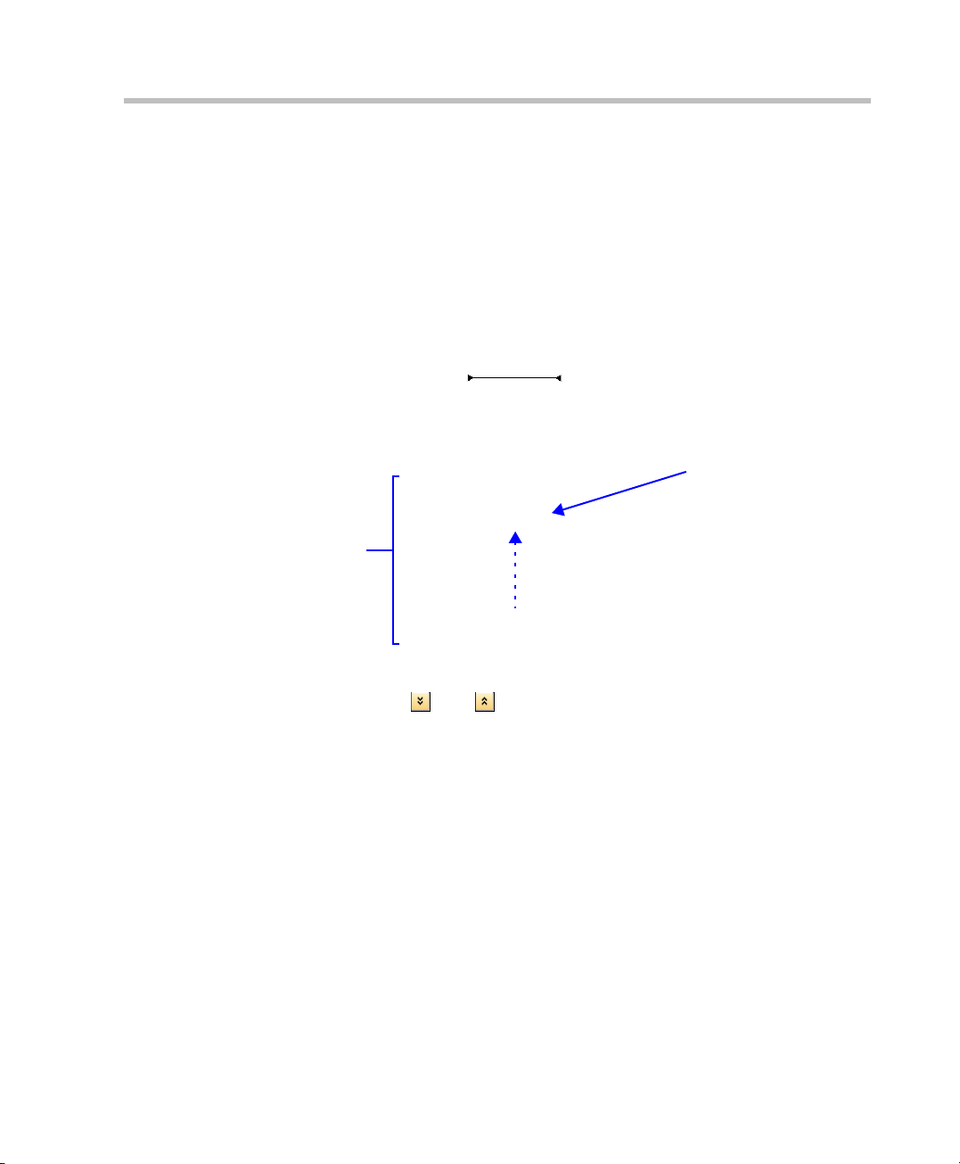
Port Usage Gauge
The Port Usage Gauge indicates the number of ports in use. It also indicates
the number of ports licensed for the system.
The red area indicates the capacity usage threshold. The usage threshold
Administrator
represents a percentage of the total number of ports available. The red
D
area flashes and a System Alert is generated when port usage reaches or
exceeds the threshold.
The default port usage threshold is 80% and can be set by the system
administrator.
Ports In Use Ports In System
Viewing Permissions
Chairperson
Operator
D
D
Usage Indicator
Usage Threshold
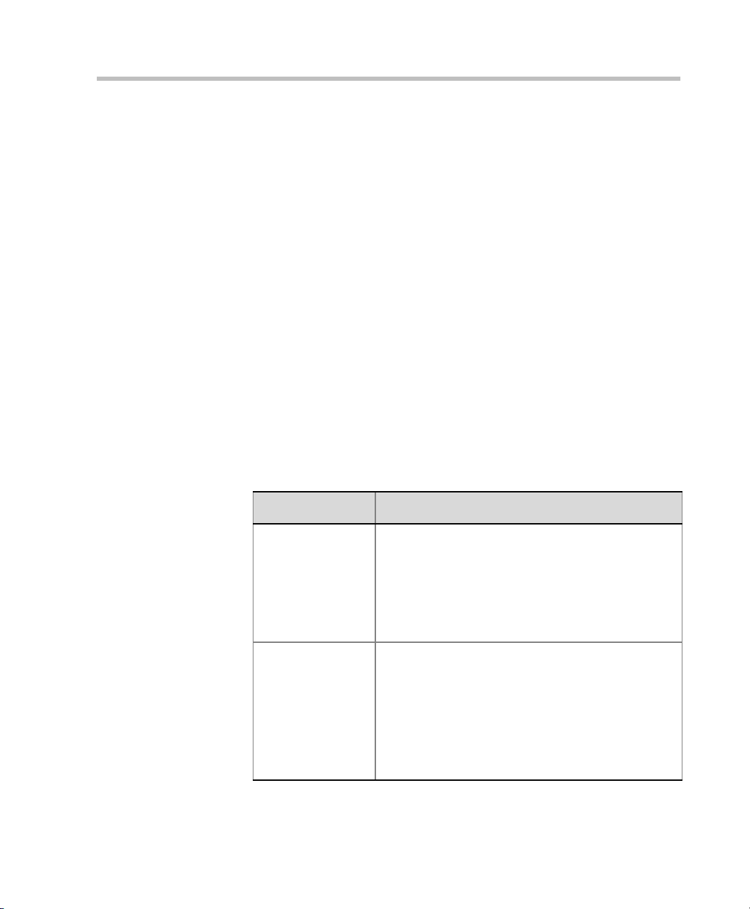
MCU State
The MCU State indicator displays one of the following:
• – The MCU is functioning normally.
Administrator
• – The MCU has a minor problem but users can
D
keep working.
• – The MCU has a major problem. MCU behavior
could be effected and attention is required.
3-7
Page 42

Chapter 3-Basic Operation
Address Book
The Address Book is a list of Participants and Groups that have been defined
on the RMX. The information in the address book enables RMX users to
easily assign participants to conferences.
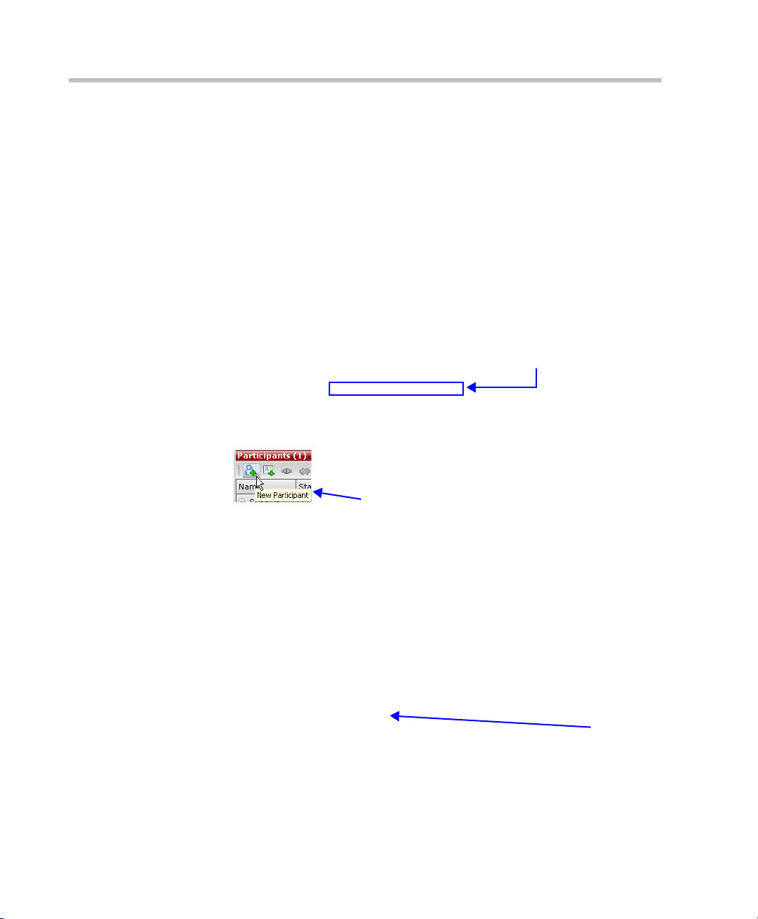
The Address Book toolbar contains six buttons:
• New Participant
• Delete Participant
•New Group
• Delete Group
• Import Address Book
• Export Address Book
Delete Participant
New Participant
New Group
Delete Group
Import Address Book
Export Address Book
3-8
Audio
Video
Group
Click
to hide
Address
Book
Address Book entries are listed according to:
• Type – whether an individual Participant or a Group of participants.
• Direction – Dial-in or Dial-out.
• Name – of the participant or group.
• IP Address – of the participant.
Page 43

Displaying and Hiding the Address Book
The first time you access the RMX Web Client, the Address Book pane is
displayed. You can hide it by clicking the anchor pin ( ) button.
The Address Book pane closes and a tab appears in the top right corner of
the screen.
Click the tab to re-open the Address Book.
Customizing the Main Screen
You can customize the main screen according to your preferences. Pane
sizes can be changed, column widths can be adjusted and data lists can be
sorted.
Polycom RMX 2000 Getting Started Guide
Click tab to open Address Book
Customization settings are automatically saved for each logged-in user.
The next time the RMX Web Client is opened, the settings appear as they were
when the user closed the application.
To re-size a pane:
 Move the pointer over the pane border and once the pointer becomes
a click and drag the pane border to the required size and release
the mouse button.
To adjust column width:
1 In the column header row, place the pointer on the vertical field-
separator bar of the column.
2 Once the pointer becomes a , click and drag the field separator bar
to the required column size and release the mouse button.
To sort the data by any field:
1 In the Conference List or Main List View pane, click on the column
heading of the field to be used for sorting.
3-9
Page 44

Chapter 3-Basic Operation
2 Click on the column heading to toggle its sort order.
To change the order of columns in a pane:
 Click the heading to be moved and drag it to the new position. When
To restore the RMX window to its default configuration:
 In the RMX menu, click View > Restore RMX Display Defaults.
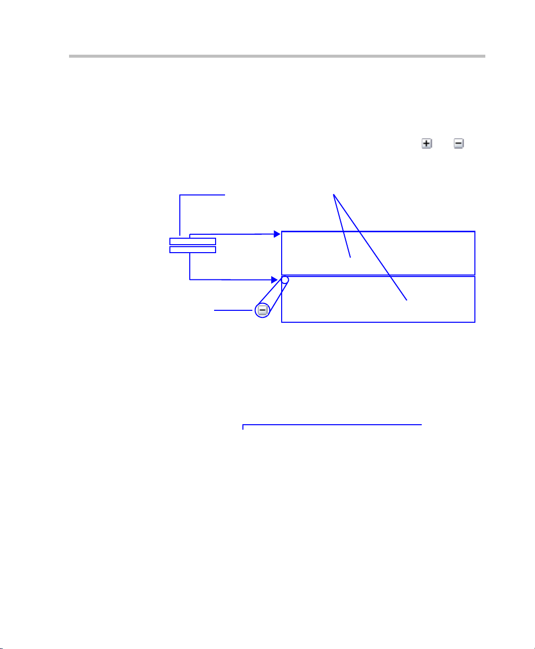
Customizing the RMX Management Pane
The RMX Management pane can be viewed either as a list or as a toolbar.
To switch between Toolbar and List Views:
 In the RMX Management pane, click the Toolbar View button to
 In Toolbar view, click the List View button to switch back to List View.
A or symbol appears in the column heading indicating the sort
order and that the list is sorted by this field.
a set of red arrows appears indicating the column’s new position,
release the mouse button.
switch to Toolbar View.
3-10
Toolbar View Button
List View
List View Button
Toolbar View
Page 45
Polycom RMX 2000 Getting Started Guide
You can move items between the Frequently Used and Rarely Used sections
depending on the operations you most commonly perform and the way
you prefer to work with the RXM Web Client.
This only works in List View because in Toolbar view, all items are
represented by icons.
To move items within and between the Frequently Used and Rarely
Used sections:
1 In the RMX Management pane click and drag the icon of the item that
you wish to move.
An indicator line ( ) appears indicating the new position
of the icon.
2 Release the mouse button when the icon is in the desired position.
The new position of the
Networks icon
List
View
The Frequently Used and Rarely Used sections can be expanded or collapsed
by clicking the and buttons.
3-11
Page 46

Chapter 3-Basic Operation
Starting a Conference
There are several ways to start a conference:
• Clicking the New Conference button in the Conferences pane,.
• Dialing in to a Meeting Room.
— A Meeting Room is a conference that is saved in the MCU. It
remains in passive mode until it is activated by the first
participant, or the meeting organizer, dialing in.
For more information about Meeting Rooms, see the Polycom RMX
2000 Administrator’s Guide, "Meeting Rooms” on page 2-1.
• Dialing in to an Ad Hoc Entry Queue which is used as the access
point to the MCU.
For a detailed description of Ad Hoc Entry Queues, see the RMX 2000
Administrator’s Guide, "Entry Queues” on page 3-1.
Starting a Conference from the Conference Pane
To start a conference from the Conference pane:
1 In the Conference pane, click the New Conference ( ) button.
The Conference – General dialog box opens.
3-12
Page 47
Polycom RMX 2000 Getting Started Guide
The system displays the conference’s default Name, Duration and the
default Profile, which contains the conference parameters and media
settings.
The RMX automatically allocates the conference ID, upon conference
start.
In most cases, you can accept the default conference ID and click OK,
or you can change the conference ID and click OK and the conference
is launched.
If you are the meeting chairperson or organizer using the RMX Web
Client to start your own meeting, you need to communicate the
default conference ID (or the one you created) to the other conference
participants so they can dial in.
You can use the General dialog box to modify the conference
parameters. If no defined participants are to be added to the
conference, or you do not want to add additional information, click
OK.
General Tab
2 Define the following parameters:
Table 3-2 New Conference – General Options
Field Description
Name The system automatically generates a unique
conference name. To modify it, enter a unique
conference name, using up to 80 chara c te rs. If the
same name is already used by another conference,
Meeting Room or Entry Queue, the RMX displays an
error message requesting you to enter a different
name. Note: This field is displayed in all tabs.
Profile The system displays the name of the default
Conference Profile. Select the required Profile from
the list.
The Conference Profile includes the Conference line
rate, media settings and general settings.For a
detailed description of Conference Profiles, see the
RMX 2000 Administrator’s Guide, "Conference
Profiles” on page 1-1.
3-13
Page 48

Chapter 3-Basic Operation
Table 3-2 New Conference – General Options (Continued)
Field Description
Duration Define the duration of the conference in hours using
the format HH:MM (default 01:00).
ID Enter the unique-per-MCU conference ID. If left
blank, the MCU automatically assigns a number
once the conference is launched. This ID must be
communicated to conference participants to enable
them to dial in.
Conference
Password
Chairperson
Password
Enter a password to be used by participants to
access the conference. If left blank, no password is
assigned to the conference. This password is valid
only in conferences that are configured to prompt for
a conference password.
Enter a password to be used by the RMX to identify
the Chairperson and grant him/her additional privileges. If left blank, no chairperson password is
assigned to the conference.
This password is valid only in conferences that are
configured to prompt for a chairperson password.
3 If all participants are undefined, dial-in and no additional
information is required for the new conference, click OK.
4 To add participants from the Participants Address Book or to define
participants (mainly dial-out participants) click the Participants tab.
3-14
Page 49

Participants Tab
This procedure is optional.
5 Click Participants.
The Participants tab opens.
Polycom RMX 2000 Getting Started Guide
Participants
List
6 Define the following parameters:
Table 3-3 New Conference – Participants Options
Field / Button Description
Participants List
Name Disp lays the participant’s name and an icon
representing the endpoint type: Audio Only or Video.
IP Address Indicates the IP address of the participant’s endpoint.
• For dial-out connection, displays the IP address of
the endpoint called by the Polycom RMX 2000.
• For dial-in connection, displays the participant’s IP
address used to identify and route the participant
to the appropriate conference.
3-15
Page 50

Chapter 3-Basic Operation
Table 3-3 New Conference – Participants Options (Continued)
Field / Button Description
Alias Name/SIP
Address
Displays the alias name of an H.323 endpoint or the SIP
URL.
Interface The network communication protocol used by the
endpoint to connect to the conference: H.323 or SIP.
Connection Dial-in – The participant dials in to the conference.
Dial-out – The RMX dials out to the participant.
Encryption Displays whether the endpoint uses encryption for its
media.
Auto (default setting) indicates that the endpoint must
connect according to the conference encryption setting.
Define a new participant.For more information on
Participant definition, see the RMX 2000 Administrator’s
Guide, "Adding a new participant to the Address Book”
on page 4-4.
Click to remove the selected participant from the
conference.
Click to add a participant from the Address Book to the
conference.
Lecturer This option is used to activate the Lecture mode. Select
the participant you want to designate as Lecturer from
the drop-down menu list of conference participants.
3-16
Page 51

Polycom RMX 2000 Getting Started Guide
To add participants from the Address Book:
7 In the Participants List, click the Add from Address Book button to
open the Participants Address Book.
8 In the Address Book, select the participants that you want to add to the
conference and click the Add button.
Standard Windows multiple selection techniques can be used in this
procedure.
9 The selected participants are assigned to the conference and appear
in the Participant List.
10 Select additional Participants or click Close to return to the
Participants tab.
3-17
Page 52

Chapter 3-Basic Operation
Using Drag & Drop to add Participants from the Address Book:
You can add participants to a conference directly from the Participants
Address Book without having to use the New Conference – Participants tab.
To drag & drop participants into the Participants List:
11 Open the Address Book.
12 Select, drag and drop the participant that you wish to add to the
conference directly from the Participant Address Book into the
Participant List.
Standard Windows multiple selection techniques can be used in this
procedure.
3-18
Info Tab
This procedure is optional.
To add information to the conference:
This information is written to the Conference Data Record (CDR) when the
conference is launched. Changes made to this information once the
conference is running are not saved to the CDR.
13 Click Info.
Page 53

The Information tab opens.
14 Enter the following information:
Table 3-4 New Conference – Info Options
Polycom RMX 2000 Getting Started Guide
Field Description
Info1, 2, 3 There are three information fields that allow you to
enter general information for the conference such as
company name, contact person etc...
Billing Enter the conference billing code if applicable.
15 Click OK.
The conference appears in the Conferences pane.
If no participants were defined or as long as no participants are
connected the conference’s Status is listed as empty and a warning
icon ( ) appears in the Status column.
The status changes when participants connect to the conference.
3-19
Page 54

Chapter 3-Basic Operation
2
assword
356
Connecting to a Conference
To dial into a conference or Meeting Room, participants must be provided
with a dialing string which can vary according to your network type,
conference password and chairperson password.
Participants dial the conference dial-in string and are connected to the
conference IVR Service. Once the correct information, such as the
conference password and chairperson password are entered, the
participants are connected to the conference.
IP Endpoint
SIP Endpoint
Maple_room@polycom.com
IP Endpoint
9
2
5
1
0
0
1
MCU
Prefix in
Gatekeeper - 925
Network
2
0
0
1
5
2
9
MCU
Maple_Room
Conference ID: 1001
Oak_Room
Conference ID: 100
P
: 71
Dial-in Connection via IVR System
The chairperson can use the chairperson password as the conference
password and does not need to enter the conference password.
Participant connecting to an HD conference must have HD capabilities and use
the same bit rate as defined for the conference, otherwise they will be
connected as Secondary (audio only participants).
Password: 34567
3-20
Page 55

Dial-in H.323 Participants
For H.323 participants, the dialing string is composed of the MCU prefix
in the Gatekeeper and the conference ID.
For example:
Gatekeeper Prefix 925
Conference ID 1001
Conference Name Maple_Room
 The participant dials
If there is no gatekeeper defined for the network, H.323 participants dial
the MCU’s signaling host IP address and the conference ID, separated
by
##.
For example:
MCU (Signaling Host) IP address
Conference ID 1001
 The participant dials 172.22.30.40##1001
Dial-in SIP Participants
Polycom RMX 2000 Getting Started Guide
9251001 or 925Maple_room
172.22.30.40
For SIP participants the dialing string is composed of the conference name
and domain name in the following format:
conference_name@domain_name
For example:
Maple_room@polycom.com
3-21
Page 56

Chapter 3-Basic Operation
2
assword
356
Conference Access Via an Entry Queue
Access via an Entry Queue allows all participants to dial the same entry
point that acts as a routing lobby. Once in the Entry Queue, participants
are guided to the conference according to the conference ID they enter.
IP Endpoint
IP Endpoint
SIP Endpoint
9
2
5
1
0
925DefaultEQ
@
Q
E
t
l
u
a
f
e
D
0
1
MCU
Gatekeeper - 925
m
o
c
.
m
o
c
y
l
o
p
Network
Prefix in
MCU
Name: DefaultEQ
Numeric ID: 1000
Maple_Room
Conference ID: 1001
1
0
0
1
2
0
0
1
Oak_Room
Conference ID: 100
P
Password: 34567
: 71
Figure 3-1: Dial-in Connecti o n vi a Ent r y Qu eu e
Dialing is done in the same way as for conferences, where the Entry
Queue ID/Name replaces the Conference ID/Name.
H.323 Participants
H.323 participants dial [Gatekeeper Prefix][Entry Queue ID/Name].
For example:
Gatekeeper Prefix 925
Entry Queue ID 1000
 H.323 participants dial
9251000
3-22
Page 57

Polycom RMX 2000 Getting Started Guide
H.323 participants can bypass the Entry Queue voice messages by adding
the correct Conference ID of destination conference to the initial dial
string:
[
Gatekeeper Prefix][EQ ID][##Destination Conference ID]
For example:
Conference ID 1001
 H.323 participants dial
9251000##1001
H.323 participants can also add the Conference Password to the initial
dial string:
[Gatekeeper Prefix][EQ ID][##Destination Conference
ID][##Password]
For example:
Conference ID 1001
Conference Password 34567
 H.323 participants dial
9251000##1001##34567
SIP Participants
Using an Entry Queue minimizes the number of conferences that require
registration with the SIP server and enables using one URI address for all
dial-in connections, using the format:
<Entry Queue name>@<domain name>
For example:
Entry Queue Name DefaultEQ
Domain Name polycom.com
 SIP participants dial DefaultEQ
@polycom.com
3-23
Page 58

Chapter 3-Basic Operation
Endpoint Names in the Video Layout
During conferences you can view the endpoint name in the endpoint’s
video layout windows. The MCU can display up to 33 characters of the
endpoint’s name, depending on the window’s layout (size).
The following is an example of endpoint name display in the Polycom
ViaVideo endpoint window:
3-24
Endpoint Name
The displayed name is determined as follows:
• The system displays the name that is defined at the endpoint.
• If the endpoint does not send its name:
— For a defined participant:
• The system displays the name from the participant
definition
— For an undefined H.323 participant:
•Display the H.323 ID alias
or display the E.164 alias
or display nothing if all the fields are empty
— For a SIP undefined participant:
• Display the SIP DisplayName field
or display the SIP Address (SIP application server)
or display the SIP ContactDisplay field
or display nothing if all the fields are empty
Page 59

Polycom RMX 2000 Getting Started Guide
• If the endpoint’s display name is changed in the RMX Web Client, it
overrides all the above.
To change the Display Name:
1 In the Participants list, double click the participant or right-click the
participant and select Participant Properties from the drop-down
menu.
The Participant Properties – Media Sources dialog box opens:
2 Enter the new Display Name in the Name field and click OK.
3-25
Page 60
Chapter 3-Basic Operation
Monitoring On Going Conferences
Conference monitoring enables you to keep track of conferences and their
participants: if all its participants are correctly connected and whether
errors or faults have occurred.
Monitoring and Operations Methods
Operation Selection
All Monitoring and Operations procedures performed during on going
conferences can be performed by either of two methods:
• Using the buttons in the toolbars.
Toolbar Buttons
3-26
Tool tip appears when cursor is positioned over button
• Right-clicking anywhere in the relevant pane and selecting an
operation from the menu.
Operations
Menu
Page 61
Polycom RMX 2000 Getting Started Guide
Using multi-select, you can monitor and perform simultaneous
operations on multiple participants in multiple conferences.
Multi-selected conferences are displayed as sublists in the Participants List
pane.
The sublists can be expanded and collapsed by clicking the and
sublist control buttons that appear next to the conference name in the
sublist headings.
Multi-selected
Conferences
Control button in
sublist header
Conference Level Monitoring
Conference level monitoring is available to the administrator, operator
and chairperson.
The Conference List pane displays information about ongoing conferences.
Participant Sublists
Status
One or more of the status indicators listed in Table 3-5 may appear in the
Status column.
3-27
Page 62

Chapter 3-Basic Operation
No status indicator means that the conference is running without
problems.
Table 3-5 Conferences – Monitoring Information
Field Description
Name
Displays conference name and type of conference:
•
– Video Conference
• – High Definition Video Conference
Status Displays the status of the ongoing conference.If there is
no problem with the participant’s connection no indication
is displayed.If one of the following statuses occur, the
appropriate indication, proceeded by a warning icon ( ).
• Audio – There is a problem with the participant’s
audio.
• Empty – No participant are connected.
• Faulty Connection – Participants are connected, but
the connection is problematic.
• Not Full – Not all the defined participants are
connected.
• Partially Connected – The connection process is not
yet complete; the video channel has not been
connected.
• Single Participant – Only one participant is
connected.
• Video – There is a problem with the participant’s
video.
ID The Conference ID assigned to the conference.
3-28
Start Time Conference start time.
End Time The time the conference is expected to end.
Page 63

Polycom RMX 2000 Getting Started Guide
Additional information about the conference can be viewed when
accessing the conference properties.
To monitor a conference:
In the Conference List pane, double click the name of the conference you
wish to monitor or right-click the conference and then click Conference
Properties.
The Conference Properties dialog box appears with the General tab open.
You can view all the conference’s properties but those that appear with a
gray background cannot be modified.
For a detailed description of Conference Level Monitoring, see the Polycom
RMX 2000 2000 Administrator’s Guide, "Conference Level Monitoring” on
page 5-3.
The Conferences pane displays the HD icon ( ) to indicate that the
conference is running in HD mode.
3-29
Page 64

Chapter 3-Basic Operation
Participant Level Monitoring
Participant Connection Monitoring
When a conference is selected in the Conference List, details of its
participants appear in the List pane.
The following participant indicators and properties are displayed:
Table 3-6 Participant Monitoring – Indicators and Properties
Field Description
Name Displays the name and type of the participant:
Audio Participant – Connected via IP phone.
Video Participant – Connected with audio and video
channels.
3-30
Status Displays the connection status of the participant:If there is
no problem with the participant’s connection no indication is
displayed.
Connected – The participant is successfully
connected to the conference.
Disconnected – The participant is disconnected
from the conference. This status applies only to
defined participants.
Waiting for Dial-in – The system is waiting for the
defined participant to dial into the conference.
Partially Connected – The connection process is
not yet complete; the video channel has not been
connected.
Faulty Connection – The participant is connected,
but problems occurred in the connection, such as
synchronization loss.
Page 65

Polycom RMX 2000 Getting Started Guide
Table 3-6 Participant Monitoring – Indicators and Properties
Field Description
Status (cont.) Secondary Connection – The endpoint’s video
channel cannot be connected to the conference and
the participant is connected only via audio.
Role Displays the participants role or function in the conference:
Chairperson – The participant is defined as the
conference chairperson. The chairperson can
manage the conference using touch-tone signals
(DTMF codes).
Lecturer – The participant is defined as the
conference Lecturer.
Lecturer and Chairperson – The participant is
defined as both the conference Lecturer and
Chairperson.
IP The participant’s IP address.
Alias Name/
The participant’s Alias Name or SIP URI.
SIP Address
Network The participant’s network connection type – H.323 or SIP.
Direction Dial-in – The participant dialed the conference.
Dial-out – The MCU dialed the participant.
Audio Displays the status of the participant’s audio channel:If
there is no problem with the participant’s audio connection
and the channel is neither muted or blocked, no indication is
displayed.
Muted – Audio channel is muted.
Blocked – Transmission of audio from the
conference to the participant is blocked.
3-31
Page 66

Chapter 3-Basic Operation
Table 3-6 Participant Monitoring – Indicators and Properties
Field Description
Video Displays the status of the participant’s video channel:If
Encryption In dicates that the end poin t is using encr yption f or it s
FECC Token Participant is the holder of the FECC token and has
there is no problem with the participant’s video connection
and the channel is neither suspended or secondary, no
indication is displayed.
Suspended – Video transmission from the endpoint
to the conference is suspended.
Secondary – Participant is connected only through
the audio channel due to problems with the video
channel.
connection to the conference.
Far End Camera Control capabilities.The FECC
token can be allocated to only one participant at a
time and remains un-allocated if no participant
requests it.
3-32
Content Token Participant is the holder of the Content token and has
content sharing permission.The Content token can
be allocated to only one participant at a time and
remains un-allocated if no participant requests it. For
more information about Content Sharing, see the
RMX 2000 Administrator’s Guide, "H.239” on
page 6-7.
For more information, see the RMX 2000 Administrator’s Guide,
"Participant Level Monitoring” on page 5-7.
Page 67

Polycom RMX 2000 Getting Started Guide
Operations Performed During On Going Conferences
Conference Level operations
Changing the Duration of a Conference
The duration of a conference is set when the new conference is created.
The default duration of a conference is 1 hour. All conferences running on
the Polycom RMX 2000 are automatically extended as long as there are
participants connected to the conference.
While a conference is running, it is possible to lengthen or shorten its
Duration by modifying its scheduled End Time.
To extend a conference manually:
1 In the Conference List pane, double-click the conference Name.
2 In the General tab, modify the End Time fields and click OK.
The End Time is changed and the Duration field is updated.
3-33
Page 68

Chapter 3-Basic Operation
To terminate a conference manually:
1 In the conference list, select the conference you wish to delete and
2 Click OK to terminate the conference.
Changing the Video Layout of a Conference
While the conference is running you can change the video layout and
select one of 24 video layouts supported by the RMX.
The initial video layout is selected in the conference Profile.
To change the video layout of a conference:
1 In the Conference Properties dialog box, select Video Settings.
click the Delete Conference ( ) button.
You are prompted for confirmation.
3-34
Video
Windows
Representation
Video
Layout
Options
Selected
Layout
Page 69

Polycom RMX 2000 Getting Started Guide
2 From the Video Layout options, select the Number of Windows to
display and the Video Layout thumbnail required and click OK.
Number of
Video
Windows
Video
Layout
Thumbnail
Selected
Layout
Video Forcing
The chairperson or operator can select which participant appears in each
of the video layout windows for any participant by using Video Forcing.
Conferences start with the layout defined in the Conference Profile.
Video Forcing applies to Dynamic Continuous Presence conferences.
Video Forcing works on two levels:
• Conference Level – Applies to all conference participants. All
participants have the same video layout.
• Participant Level – The participant’s video layout is changed. All
other conference participants’ video layouts are not affected.
Video Forcing can be cancelled by individual participants via Personal
Layout Control without affecting other participants.
For more information see “Personal Layout Control” on page 3-40.
Video Forcing Guidelines:
• A participant cannot appear in two or more windows at the same
time.
3-35
Page 70

Chapter 3-Basic Operation
• Participant level video forcing overrides conference level video
• A participant can view him/herself in a layout window, by selecting
• When different size video windows are used in video layouts such as
• When changing the Video Layout at the conference level, the video
• Windows that are not assigned any participant display the current
To video force a participant to a window:
1 In the Conference Properties dialog box, select the Video Settings tab.
2 Un-check the Auto Layout box.
3 In the window to which you want to force a participant, select the
forcing.
the Same Layout option.
1+2, 1+3, 1+4, etc., a participant can only be forced, in Personal Layout,
to a video window of the same size as that selected for him/her in
Conference Layout.
forcing settings are not applied to a new layout, and video switching
is audio-activated. The video forcing setting are saved and applied
the next time the layout is selected.
speaker and last speakers.
participant’s name from the list of conference participants.
3-36
Selected
Layout
4 Repeat step 3 to force participants to other windows.
List of
Conference
Participants
Video
Windows
Page 71

5 Click OK.
To cancel Video Forcing for a window:
 In the window’s Participants list, select Auto Select.
In such a case, switching between participants is audio activated.
Participant Level Operations
Participant Level Operations enable you to modify and control the
connections and statuses of participants in on going conferences.
Table 3-7 lists the Participant Level Operations that can be performed.
Table 3-7 Participant Level Operations
Polycom RMX 2000 Getting Started Guide
Menu
Option
New
Participant
Add
Participant
From
Address
Book
Connect
Participant
Disconnect
Participant
Delete
Participant
Mute
Audio
Unmute
Audio
Button Description
Define a new participant.For more information about
the New Participant dialog box tab, see Table 3-3 on
page 3-15.
Open the Address Book to select the participant for
the conference.For more information about the
Address Book, see RMX 2000 Administrator’s Guide,
"Address Book” on page 4-1.
Connect a disconnected defined dial-out participant
to the conference.
Disconnect the participant from the conference.
Delete the selected partici pants from the conference.
Mute the audio transmission from the participant to
the conference.The Audio Muted indicator appears in
the Participants List and the Unmute Audio button
( ) becomes active.
Participant’s audio transmission to the conference
resumes. The Mute Audio button ( ) becomes
active.
3-37
Page 72

Chapter 3-Basic Operation
Table 3-7 Participant Level Operations (Continued)
Menu
Option
Suspend
Video
Resume
Video
Block
Audio
Unblock
Audio
Add
Participant
to Address
Book
Button Description
Suspend the video transmission from the participant
to the conference. The suppressed participant’s video
is not transmitted to the conference but the participant
still receives conference video.The Suspend Video
indicator appears in the Participants List and the
Resume Video button ( ) becomes active.
Participant’s video transmission to the conference
resumes.The Suspend Video button becomes active
().
To block the audio transmission from the conference
to the participant. When blocked, the participant can
still be heard by the conference.The Audio Blocked
indicator appears in the Participants List and the
Unblock Audio button ( ) becomes active.
Conference audio transmission to the participant
resumes.The Block Audio button ( ) becomes
active.
Add selected participant’s details to the Participant
Address Book.
3-38
Abort
H.239
Session
Change to
Chairperson
Change to
Regular
Participant
Select to withdraw the Content Token from the
participant.
Define the selected participant as the conference
leader/chairperson.
Define the chairperson as a regular participant
without chair privileges.
Page 73

Polycom RMX 2000 Getting Started Guide
Table 3-7 Participant Level Operations (Continued)
Menu
Option
Participant
Properties
Button Description
Select for a detailed view of all Participant Properties.
For more information about Participant Properties,
see the RMX 2000 Administrator’s Guide, "Participant
Level Monitoring” on page 5-7.
Video Forcing
Video Forcing Guidelines:
See "Video Forcing Guidelines:” on page 3-35.
To video force a participant to a window:
1 In the Participants list, double click the participant or right-click the
participant and select Participant Properties from the drop-down
menu.
The Participant Properties – Media Sources dialog box opens:
List of
Conference
Participants
Selected
Layout
2 In the Layout Type menu, select Personal
3 In the window to which you want to force a participant, select the
participant’s name from the list of conference participants.
3-39
Page 74

Chapter 3-Basic Operation
4 Repeat step 3 to force participants to other windows.
5 Click OK.
To cancel Video Forcing for a window:
 In the Layout Type menu, select Conference.
In such a case, switching between participants is audio activated.
Personal Layout Control
Personal Layout Control With the RMX Web Client
RMX users can use the RMX Web Client to the change the
of individual participants without affecting the
participants.
To change a participant Video Layout:
1 In the Participants list, double click the participant or right-click the
Video Layouts
Video Layouts of other
participant and select Participant Properties from the drop-down
menu.
The Participant Properties – Media Sources dialog box opens:
Video
Windows
Representation
3-40
Number of
Video
Windows
Selected
Layout
Video
Layout
Thumbnail
2 In the Layout Type drop-down menu, select Personal
3 Select the number of Video Windows.
4 Select the Video Layout
Page 75

Polycom RMX 2000 Getting Started Guide
5 Click OK.
To cancel Video Forcing for a window:
 In the Layout Type menu, select Conference.
The participants Video Layout reverts to that of the conference.
Personal Layout Control With Click&View
With the Click&View application, participants can change their
Personal
Layouts via DTMF codes entered from their endpoints. This option is
available only if the Click&View option is selected in the IVR Service used
in the conference.
To change Personal Layout with Click&View:
1 Enable Click&View – on the endpoint’s keypad, enter .
The Click&View application is displayed on the screen.
When using a Polycom VSX endpoint a must be entered to enable the
keypad. The full Click&View entry sequence is: , .
3-41
Page 76

Chapter 3-Basic Operation
2 On the endpoint’s keypad, press the number corresponding to the
The Personal Layout options menu is displayed on the video screen.
number of video squares you wish to select.
For example, if you want a four-square video layout, press .
The video window layout of your screen changes to the first fourwindow layout as follows:
3-42
Repeated presses of the key, within eight seconds, cycles through
the following series of four-square layout options:
options:
Pressing an any multi-square layout forces the current speaker to
the top left window.
Pressing in full view forces the next participant to full view.
Pressing returns the video layout to the conference layout.
Page 77
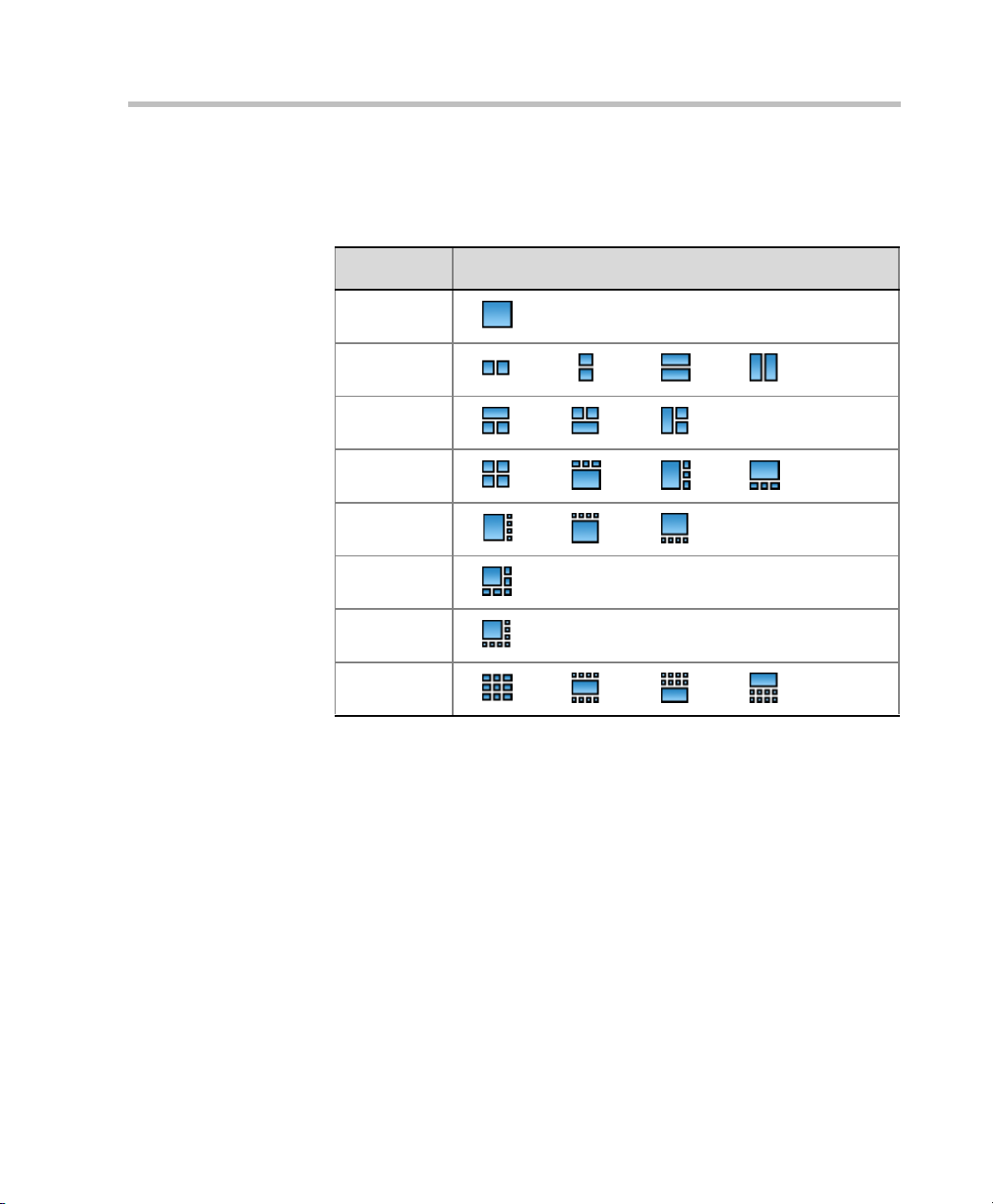
Polycom RMX 2000 Getting Started Guide
The following table summarizes the Video Layout options available
via Click&View.
Table 3-8 Video Layout Options
DTMF Code Layout Optio ns
1
2
3
4
5
6
8
9
Conference Control Using DTMF Codes
Participants and chairpersons can manage their connection to ongoing
conferences from their endpoints, using touch-tone signals (DTMF codes)
from their endpoints.
Chairpersons can also control an ongoing conference using DTMF codes.
Permissions for DTMF actions to be performed by all conference
participants or by chairperson only are configured in the Conference IVR
Service assigned to the conference.
For more information about IVR Services see "Defining a New IVR Service”
on page 9-9.
Table 3-9 below contains a list of DTMF Codes.
3-43
Page 78

Chapter 3-Basic Operation
.
Table 3-9 Conference IVR Service Properties - DTMF Codes
Operation DTMF String Permission
Mute My Line *6 All
Unmute My Line #6 All
Increase Broadcast Volume *9 All
Decrease Broadcast Volume #9 All
Mute All Except Me *5 Chairperson
Cancel Mute All Except Me #5 Chairperson
Change Password *77 Chairperson
Mute Incoming Participants *86 Chairperson
Unmute Incoming Participants #86 Chairperson
Play Help Menu *83 All
3-44
Enable Roll Call *32 Chairperson
Disable Roll Call #32 Chairperson
Roll Call Review Names *33 Chairperson
Roll Call Stop Review Names #33 Chairperson
Terminate Conference *87 Chairperson
Start Click&View ** All
Change To Chairperson *78
Increase Listening Volume *76
Decrease Listening Volume #76 All
Override Mute All Configurable All
All
All
Page 79
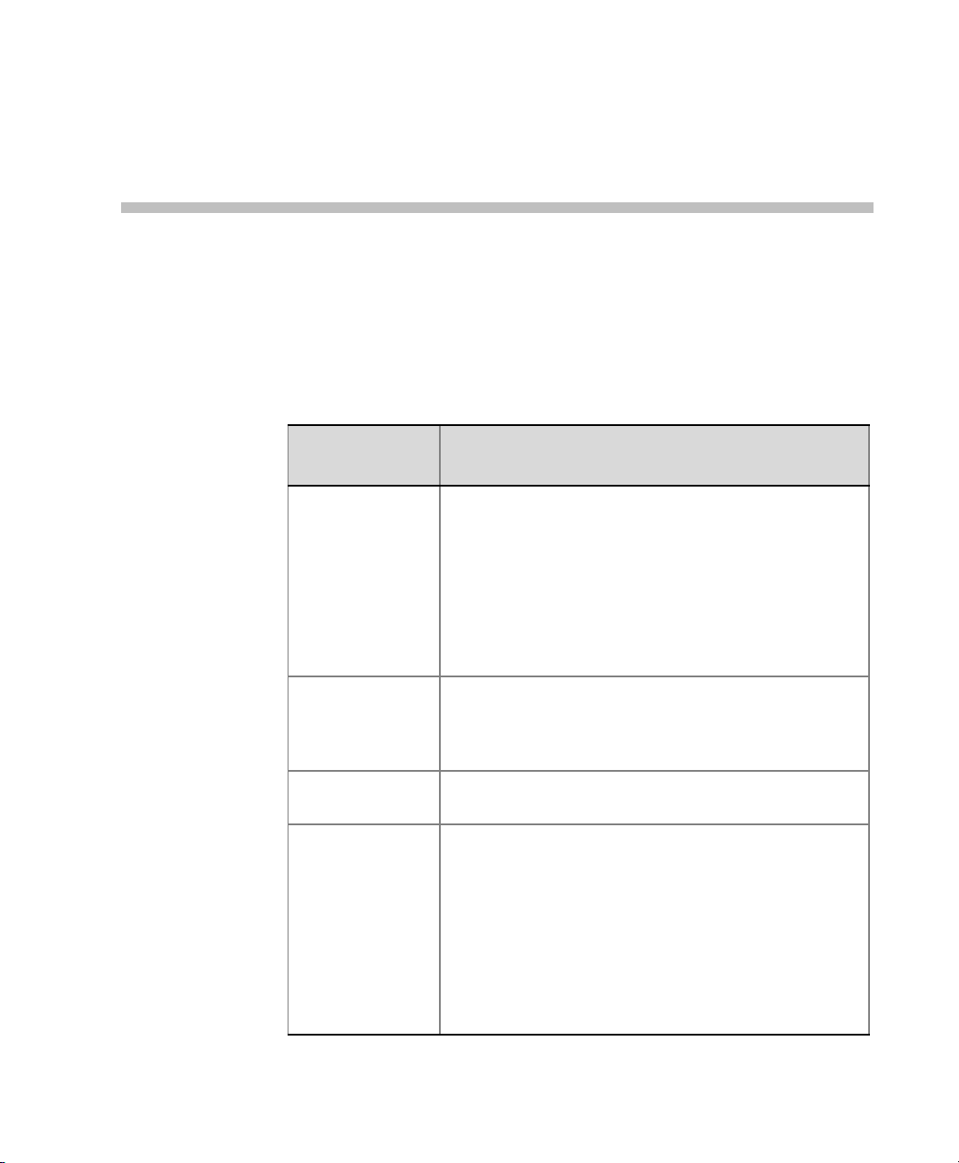
Glossary
This appendix lists the terms and abbreviations that are related to the
Polycom RMX 2000, and are commonly used in the RMX 2000
documentation
Appendix A
.
Abbreviation/
Term
Bandwidth Defines the information carrying capacity of a channel. In
Bps, Kbps Bits and kilobits per second; a unit of bandwidth, that is
Carrier A telephone or other company that provides
CIF, 4CIF, QCIF Common Intermediate Format, an optional part of the
Explanation
analog systems, it is the difference between the highest
frequency that a channel can carry and the lowest,
measured in hertz. In digital systems, bandwidth is
measured in bits per second. The larger a connection's
bandwidth, the more data can be transmitted in a given
amount of time, allowing for greater video resolution and
more sites in a conference. For more information, see
Line Rate.
the amount of data that can flow during one second over a
communications line (using a transmission medium).
1 Kbps=1000 Bps
telecommunication transmission services.
ITU-T's H.261 and H.263 standards. CIF specifies 288
non-interlaced luminance lines, that contain 176 pixels.
CIF can be sent at frame rates of 7.5, 10, 15, or 30 per
second. When operating with CIF, the amount of data to
transmit cannot exceed 256 K bits (where K equals
1024).The CIF video format has the capacity to transmit
video images of 352x288 pixels at 36.45 Mbps and 30
frames per second. A 4CIF format has four times the
capacity of CIF; QCIF has quarter the capacity of CIF.
Page 80

Appendix A-Glossary
Abbreviation/
Term
Explanation
Codec Coder-decoder. A device that converts voice and video
into digital code, and vice versa. Refers to the endpoint
video camera and video board that are used for
videoconferencing.
Conference C onnection between two or more endpoints exchanging
video and audio information. If only two endpoints are
involved, a conference is called point-to-point and no
MCU is required. If more than two endpoints are involved,
it is called a multipoint conference, and an MCU
(Multipoint Control Unit) is required as the management
system. For more information, see MCU.
DTMF Dual Tone Multi Frequency. A system of coded signals
used by touch-tone telephones in which a specific sound,
frequency or tone is assigned to each key so that the
signal can be easily recognized by a computer. The codes
enable data input and control of voice-processing
systems. DTMF signals can pass through the entire
connection to the destination device and therefore are
used for remote control after the connection with the MCU
is established.
Endpoint A hardware device, or set of devices, that can call, and be
called by an MCU or another endpoint. For example, an
endpoint can be a phone, a camera and microphone
connected to a PC or an integrated Room System
(conferencing system).
A-2
FECC Far End Camera Control. In certain video cameras, the
accompanying software that enables a participant to
control a remote camera. Used in Continuous Presence
video conferences in conjunction with the LSD option. For
more information, see LSD.
Frame A group of bits that make up an elementary block of video
data for transmission by certai n p rotocols.
Frame Rate The number of video frames displayed on-screen during
one second, measured in fps (frames per second).
G.711 ITU-T audio algorithm, 64Kbps, 3.4 kHz.
Page 81

Polycom RMX 2000 Administrator’s Guide
Abbreviation/
Term
Explanation
G.722 ITU-T audio algorithm, 64Kbps, 7 kHz.
G.728 ITU-T audio algorith m, 16Kbps, 3.4 kHz.
Gatekeeper A type of server that performs two main functions:
translates LAN alias addresses of terminals and gateways
to IP addresses and provides bandwidth management.
H.221 ITU-T standard that defines how to multiplex video, audio,
control, and user data into one serial bit stream.
H.230 ITU-T standard that defines simple multipoint control
systems procedures and describes network maintenance
functions.
H.231 ITU-T standard that defines a set of MCU functions and
operational requirements.
H.242 ITU-T standard that defines initiation of communications
between systems and capabilities negotiation procedures.
H.243 ITU-T standard that defines initiation of communications
between systems and capabilities negotiation procedures
in multipoint conferences.
H.261 ITU-T standard that defines the Px64 video coding
algorithm.
H.263 ITU-T standard that provides improved compression and
quality of video images at a line rate lower than 384 Kbps.
This standard is not supported by all codecs.
H.264* A proprietary Polycom Video compression standard.
H.264 ITU-T standard that provides improved compression and
quality of video images in lower line rate connections and
is part of the Highest Common mechanism in Video
Switching conferences.
H.320 ITU-T standard that defines how the H-series video
conferencing recommendations work together.
H.323 ITU-T standard for audio, video and data communications
across IP-based (LAN) networks, including the Internet.
A-3
Page 82

Appendix A-Glossary
Abbreviation/
Term
Explanation
IP Internet Protocol. The working protocol that forms the
basis of the internet.
ISDN Integrated Services Digital Network. A set of protocol and
interface standards (voice, video and data) that comprise
a telephone network. There are two types of ISDN lines:
BRI and PRI.
ITU-T Standard International Telecommunications Union,
Telecommunication Standardization Sector (formerly
CCITT). An international group that produces official
standards for telecommunications.
LAN Local Area Network. A group of computers and other
devices linked via a network’s operating system.
Line Rate The amount of bandwidth used by a communication
device, measured in Kbps (kilobits per second).
LDAP Ligh tweight Directory Access Protocol.
MCU Multipoint Control Unit. Device which allows more than
two sites to be connected in a video conference.
Null modem cable A serial cable designed to eliminate the need for
communication equipment when two digital devices are
directly connected to each other.
A-4
Participant A person using an endpoint to connect to a conference.
When using a Room System, several participants use a
single endpoint.
QCIF Qua rter CIF. A video format with image size of 176x144
pixels that transmits 9.115 Mbps at 30 frames per second
(a quarter of the capacity of CIF). For more information,
see CIF.
QoS Quality of Service. QoS defines the performance of a
network service, such as the average delay between
packets.
RS-232 A standard for serial interface connection.
Page 83

Polycom RMX 2000 Administrator’s Guide
Abbreviation/
Term
Explanation
SIP Session Initiation Protocol. An application-layer protocol
designed to work over IP networks. A SIP service defines
the properties and the IP addresses of the SIP network
components.
T1 Line An 1.5 Mb digital switched line used in the United States.
ToS Type of Service. ToS defines optimization tagging for
routing audio and video packets.
WAN Wide Area Network. A communications network that
services a geographical area larger than the LAN.
Whiteboard An on-screen shared notebook for placement of shared
documents.
A-5
Page 84

Appendix A-Glossary
A-6
 Loading...