

Page 1

MGC WebCommander
Web Server Manager
User’s Guide
Ve rsion 9.0
Page 2

Copyright © 2007 Polycom, Inc.
All Rights Res erved
Catalog No. DOC2137C
Version 9.0
Proprietary and Confidential
The information contained herein is the sole intellectual property of Polycom, Inc. No distribution, reproduction or
unauthorized use of these materials is permitted without the expressed written consent of Polycom, Inc. Information
contained herein is subject to change without notice and does not represent commitment of any type on the part of
Polycom, Inc. Polycom and Accord are registered trademarks of Polycom, Inc.
Notice
While reasonable effort was made to ensure that the information in this document was complete and accurate at the time
of printing, Polycom, Inc., can n ot assume responsib ility for any errors. Ch an ges and/or correcti ons to th e information
contained in this document may be incorporated into future issues.
Page 3

Table of Contents
Before You Begin . . . . . . . . . . . . . . . . . . . . . . . . . . . . . . . . . . 1-1
Overview . . . . . . . . . . . . . . . . . . . . . . . . . . . . . . . . . . . . . . . . . . . . . . . 1-1
MGC Web Server Architecture . . . . . . . . . . . . . . . . . . . . . . . . . . 1-1
The Network Server . . . . . . . . . . . . . . . . . . . . . . . . . . . . . . . . . . 1-2
About this User’s Guide . . . . . . . . . . . . . . . . . . . . . . . . . . . . . . . . . . . 1-4
Prerequisites . . . . . . . . . . . . . . . . . . . . . . . . . . . . . . . . . . . . . . . . . . . . 1-5
Conventions . . . . . . . . . . . . . . . . . . . . . . . . . . . . . . . . . . . . . . . . . . . . 1-5
MGC Web Server Manager Basics . . . . . . . . . . . . . . . . . . . . . 2-1
Starting the MGC Web Server Manager Application . . . . . . . . . . . . . 2-3
The Web Server Manager Toolbar . . . . . . . . . . . . . . . . . . . . . . . 2-6
Upgrading from a Previous Version . . . . . . . . . . . . . . . . . . . . . . 2-7
Displaying the Database Tables . . . . . . . . . . . . . . . . . . . . . . . . . . . . 2-10
Connecting to the MGC Web Server . . . . . . . . . . . . . . . . . . . . . . . . 2-12
Connecting/Disconnecting to/from an MCU . . . . . . . . . . . . . . . . . . 2-13
Connecting to an MCU . . . . . . . . . . . . . . . . . . . . . . . . . . . . . . . 2-13
MCU Statuses . . . . . . . . . . . . . . . . . . . . . . . . . . . . . . . . . . . 2-14
Disconnecting from an MCU . . . . . . . . . . . . . . . . . . . . . . . . . . 2-14
Setting the Communication Parameters . . . . . . . . . . . . . . . . . . . . . . 2-15
Setting Defau lts . . . . . . . . . . . . . . . . . . . . . . . . . . . . . . . . . . . . 3-1
Defining Conference Defaults . . . . . . . . . . . . . . . . . . . . . . . . . . . . . . 3-3
Defining Participant Defaults . . . . . . . . . . . . . . . . . . . . . . . . . . . . . . 3-36
Defining MGC Manager Defaults . . . . . . . . . . . . . . . . . . . . . . . . . . 3-49
User Defined Defaults . . . . . . . . . . . . . . . . . . . . . . . . . . . . . . . . 3-51
Managing the Default Sets . . . . . . . . . . . . . . . . . . . . . . . . . . . . . . . . 3-55
Defining a Default Set as Global Defaults Set . . . . . . . . . . . . . 3-56
Assigning a Default Set to other Users . . . . . . . . . . . . . . . . . . . 3-57
Designating a Database as the Private or Global Default
Database . . . . . . . . . . . . . . . . . . . . . . . . . . . . . . . . . . . . . . . . . . 3-58
Default Conference Templates . . . . . . . . . . . . . . . . . . . . . . . . . 3-58
Options Settings . . . . . . . . . . . . . . . . . . . . . . . . . . . . . . . . . . . 4-1
i
Page 4

Table of Contents
Auto Cascade . . . . . . . . . . . . . . . . . . . . . . . . . . . . . . . . . . . . . . . . . . . 4-2
Auto Cascading Mechanisms . . . . . . . . . . . . . . . . . . . . . . . . . . . 4-2
Chairperson Activation . . . . . . . . . . . . . . . . . . . . . . . . . . . . 4-3
Implementation of Chairperson DTMF features . . . . . . . . . 4-3
Auto Cascading Guidelines . . . . . . . . . . . . . . . . . . . . . . . . . . . . 4-4
Auto Cascade Configuration . . . . . . . . . . . . . . . . . . . . . . . . . . . . 4-4
Configuring the Cascading Links using the Web Server
Manager . . . . . . . . . . . . . . . . . . . . . . . . . . . . . . . . . . . . . . . . 4-5
MCU Redundancy . . . . . . . . . . . . . . . . . . . . . . . . . . . . . . . . . . . . . . . 4-8
Redundancy Guidelines . . . . . . . . . . . . . . . . . . . . . . . . . . . . . . . 4-9
MCU Redundancy Configuration . . . . . . . . . . . . . . . . . . . . . . . 4-10
MCU Backup . . . . . . . . . . . . . . . . . . . . . . . . . . . . . . . . . . . . . . . . . . 4-12
Defining the Backup Parameters . . . . . . . . . . . . . . . . . . . . . . . 4-12
Automatic Email Language Formatting . . . . . . . . . . . . . . . . . . . . . . 4-14
Configuring the Sender’s & Meeting Organizer’s Default E-mail
Addresses . . . . . . . . . . . . . . . . . . . . . . . . . . . . . . . . . . . . . . . . . . . . . 4-21
Application Error Information . . . . . . . . . . . . . . . . . . . . . . . . . . . . . 4-24
Administrator Email Notification Settings . . . . . . . . . . . . . . . . . . . . 4-26
Administrator’s Tasks . . . . . . . . . . . . . . . . . . . . . . . . . . . . . . . 5-1
Defining an MCU . . . . . . . . . . . . . . . . . . . . . . . . . . . . . . . . . . . . . . . . 5-1
Viewing the MCUs List . . . . . . . . . . . . . . . . . . . . . . . . . . . . . . . 5-4
Sorting the MCUs List . . . . . . . . . . . . . . . . . . . . . . . . . . . . . 5-4
Defining a New Label . . . . . . . . . . . . . . . . . . . . . . . . . . . . . . . . . . . . 5-5
Viewing the Labels List . . . . . . . . . . . . . . . . . . . . . . . . . . . . . . . 5-6
Sorting the Labels List . . . . . . . . . . . . . . . . . . . . . . . . . . . . . 5-6
Defining Permissions . . . . . . . . . . . . . . . . . . . . . . . . . . . . . . . . . . . . . 5-7
Viewing the Permissions List . . . . . . . . . . . . . . . . . . . . . . . . . . 5-18
Sorting the Permissions List . . . . . . . . . . . . . . . . . . . . . . . . 5-19
Predefined Permissions . . . . . . . . . . . . . . . . . . . . . . . . . . . . . . . 5-19
Defining a New User . . . . . . . . . . . . . . . . . . . . . . . . . . . . . . . . . . . . 5-24
Viewing the Users List . . . . . . . . . . . . . . . . . . . . . . . . . . . . . . . 5-30
Sorting the Users List . . . . . . . . . . . . . . . . . . . . . . . . . . . . . 5-30
Automatically Adding Authenticated Windows Users to the Users
List . . . . . . . . . . . . . . . . . . . . . . . . . . . . . . . . . . . . . . . . . . . . . . 5-31
ii
Page 5

Manually Adding Windows Users to the Users List . . . . . . . . . 5-32
Assigning Users to Groups . . . . . . . . . . . . . . . . . . . . . . . . . . . . 5-33
Ad Hoc Conferencing and Conference Access Using
WebCommander for Authentication . . . . . . . . . . . . . . . . . . . . . 5-36
Ad Hoc Conferencing using WebCommander Server as the
External Database Application for Conferenc e Initiation
Authentication . . . . . . . . . . . . . . . . . . . . . . . . . . . . . . . . . . . 5-37
Conference Access Authentication Request using
WebCommander as the External Database Application . . . 5-40
Conference Access - Chairperson Password Authentication
Request using WebCommander as the External Database
Application . . . . . . . . . . . . . . . . . . . . . . . . . . . . . . . . . . . . . 5-42
Defining Groups . . . . . . . . . . . . . . . . . . . . . . . . . . . . . . . . . . . . . . . . 5-45
Defining a New Group . . . . . . . . . . . . . . . . . . . . . . . . . . . . . . . 5-46
Setting the Access Rights to the Group . . . . . . . . . . . . . . . . . . . 5-48
Default Group . . . . . . . . . . . . . . . . . . . . . . . . . . . . . . . . . . . . . . 5-50
New Private Groups . . . . . . . . . . . . . . . . . . . . . . . . . . . . . . . . . 5-51
Defining Personal Scheduler Templates . . . . . . . . . . . . . . . . . . . . . . 5-54
Refreshing the Database List . . . . . . . . . . . . . . . . . . . . . . . . . . . . . . 5-55
Refreshing the Database . . . . . . . . . . . . . . . . . . . . . . . . . . . . . . . . . . 5-56
Appendix A: Using a Web Portal to Link with the
WebCommand e r . . . . . . . . . . . . . . . . . . . . . . . . . . . . . . . . . . . A-1
Embedding the WebCommander in the Web Portal . . . . . . .A-3
Creating the CustomerUser Table . . . . . . . . . . . . . . . . . . . . . A-3
Creating the Links from the Web Portal to the
WebCommander . . . . . . . . . . . . . . . . . . . . . . . . . . . . . . . . . .A-4
Appendix B: Monitoring a Conference in the WebCommander
using a URL or Form . . . . . . . . . . . . . . . . . . . . . . . . . . . . . . . . B-1
Optional Parameter Scenario Description . . . . . . . . . . . . . . .B-1
URL Format . . . . . . . . . . . . . . . . . . . . . . . . . . . . . . . . . . . . .B-2
iii
Page 6

Table of Contents
iv
Page 7
Before You Begin
I
(
)
r
Overview
The MGC Web Server Manager application is the user interface to the
MGC Web Server. It allows the user to communicate via the Web Server
with the MCUs. It provides dat abase access via the Web pages and manages
the Web site that contains the reservation pages.
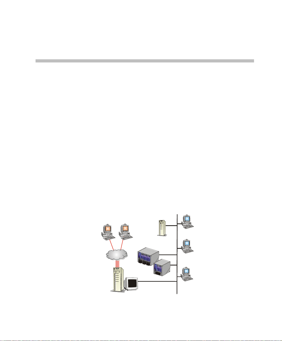
MGC Web Server Architecture
The MGC Web site is a location on a computer network. It contains
reservation information in the form of pages that can be accessed by users
logging into the site with browser applications such as Microsoft Internet
Explorer or Netscape Communicator.
The Internet client connects to the Web site located on the Internet server
and, via the MGC Web Server, gains access to the reservation pages, the
database tables, and the MCU that runs the conference.
nternet users
Access the
MGC WebComman der
site via Internet Browser
1
MGC Manage
Application
MGC Manager
Application
MGC Manager
Application
LAN
Hosts the:
* MGC Web Server
* MGC Web Server
Manager application
* MGC WebCommander
site
Database Server
Internet
Internet Server and
optional
Public Database
MCUs
1-1
Page 8
Chapter 1 - Before You Begin
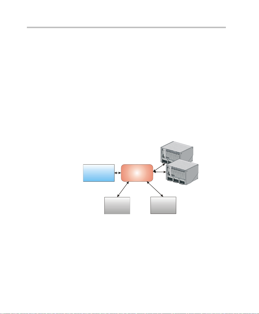
The Network Server
The network server contains the following applications:
• Database Server (SQL server or the Access application): enables
access to various database tables, such as MCU list, Users list, and
Groups
• Internet Information Services (IIS) Server: runs the Web pages and
enables users to access these pages via the Internet and make
conference reservations
• MGC Web Server: communicates with the IIS server, the Database
server, and the MCUs. This is the core of all the data exchange
performed in the Web site. Using the MGC Web Server Manager
application, users manage the MCUs connected to the Server, add
database accesses via the Web pages, and manage the reservation
pages.
1-2
MGC Web
Server
Manager
Application
Internet
Information
System
MGC
Web Server
Database
Server
The SQL server and the IIS server can be installed on separate servers,
however it is recommended that all three server-applications be installed on
the same network computer.
Page 9

MGC Web Server Manager User’s Guide
From the MG C WebCommander Server Manager the following tasks are
performed:
• Connect/disconnect MCUs
• Define access rights (Permissions) to the various modules of t he MGC
Web Server Manager application
• Define Groups to organize the dat ab ase. Users can onl y acc ess Gr oups
to which they are assigned. Reservation and Participant templates are
created from within a Group and can be viewed only by Users who
have access rights to that Group.
• Define the MGC Web Server Manager Users and their access rights
• Define the conference, participant and general system default
parameters. Users cannot modify most of these parameters if they do
not have the appropriate access rights.
This guide describes the MGC Web Server Manager features.
1-3
Page 10

Chapter 1 - Before You Begin
About this User’s Guide
The MGC WebCommander Web Server Manager User Guide includes the
following topics:
• Chapter 1 - Overview
Provides a general description of MGC WebCommander Server
Manager, its configuration and its main features.
• Chapter 2 - MGC WebCommander Server Manager Basics
Includes information you need to get the MGC WebCommander
Server Manager application running and describes the application's
main window, menu, toolbar, displaying the database tables,
connecting to the MGC Web Server and connecting to MCUs.
• Chapter 3 - Setting Defaults
Includes step-by-step instructions for setting up and managing default
sets for conference templates, participant templates, User Defined field
titles and various system parameters.
• Chapter 4 - Options Settings
Information you need to configure the Optional Settings of the Web
Server Manager.
• Chapter 5 - Administrator’s Tasks
Includes step-by-step instructions for defining new MCUs,
Permissions, Groups, Users, Labels and MGC Personal Scheduler
templates. These tasks can be performed by users with system
administrator permission only.
• Appendix A - Using a Web Portal to Link with the
WebCommander
Three WebCommander conferencing features can be accessed from a
Web Portal via links that are available in the Web Portal
• Appendix B - Monitoring a Conference in the WebCommander
using a URL or Form
You can open a moni tor in g window of a sin gle conference in any Webbased application by adding the conference URL to that application.
1-4
Page 11

Prerequisites
This document assumes that the user has the following knowledge:
• Familiarity with the Windows NT environment and interface
• Basic knowledge of video conferencing concepts
Conventions
Before using the MGC WebCommander Server Manager application, it
is important to unders tand t he te rms and co nventi ons use d in this Guide.
• The term "Double-click" is used when you need to click twice on an
• The term "Select" or "Click" is used to highlight a part of the window,
• The term "Right-click" is used when you press the right mouse button
• The term "Click OK" means that you can either click the OK button
• Keyboard keys appear in capital letters, between these two symbols
• The plus sign (+) between two key n ames indicate s that you must p ress
• Bold type appearing in the tex t, or in a procedure ind icates the word o r
• Italic type appearing in the text or in a proce dure indi cates the name of
• Tips and notes appear in a different typeface:
MGC Web Server Manager User’s Guide
entry to modify it.
dialog box or menu, to be changed with your next action.
on an entry to open a pop-up menu.
with the mouse, or press the <Enter> key on the keyboard.
< >. For example, the Shift key appears as <Shift>.
and hold down one key while pressing down the second key. For
example, "press <Alt>+<P> means that you press and hold down the
Alt key while you press the P key.
the character that you should type into a t ext box from the keyboar d. It
is also used to indicate the name of the menu, button or function that
you should select.
menu, dialog box or field from which an option should be selected or
into which parameters should be entered.
This is an example of notes that you may encounter throughout this Guide.
1-5
Page 12

Chapter 1 - Before You Begin
1-6
Page 13
MGC Web Server Manager Basics
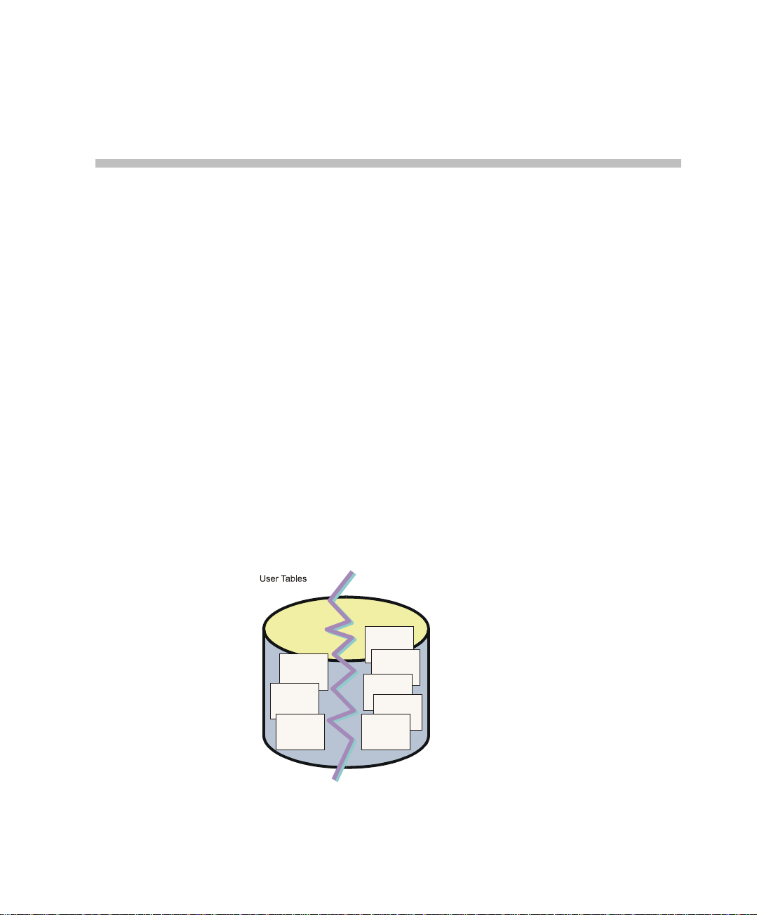
The MGC Web Server Manager enables users access to the database. The
database is divided into two modules:
• Administrative tables – the configuration tables that enable the
administrator and users who have the right to modify these tables to
define MCUs, system Defaults, Labels, Permissions, Users and Groups.
In addition, the administrator can perform maintenance and
configuration tasks relating to the database itse lf. The configuration is
performed through the MGC Web Server Manager application.
• User T ables – This m odule is divided into two segm ents: P artici pants &
Conference Templates and Master Templates. The Participants an d
Conference T emplates segmen t includes the Participant and Conference
templates that are organized in Groups. Users can only man age
templates assigned to Groups to which they have access rights. The
Groups and their access rights are defined in the MGC Web Server
Manager module. The Master Templates segment includes Master
templates that are organized in Master Template Groups (usually other
than the Participants and Conference Template Groups).
Administrative
Tables
2
Master
Templates
Table
Participants
Table
Reservations
Table
Database
Labels Table
MCUs T able
Permissions
Table
Users Table
Groups Table
2-1
Page 14

Chapter 2 - MGC Web Server Manager Basics
Important!
When both the MGC WebCommander and the MGC Manager applications
use the same database, the administrator tables defined in the MGC Web
Server Manager will apply to the MGC Database Manager and vice versa.
Therefore, the various tables may include parameters that apply only to the
WebCommander and others that will apply only to the MGC Manager. Users
may access the database via the MGC Web Server Manager or the MGC
Database Manager and perform changes in the administrator tables. These
changes will apply to both applications.
This manual describes the various Web Server Manager tables and their
configurations.
2-2
Page 15
MGC Web Server Manager User’s Guide
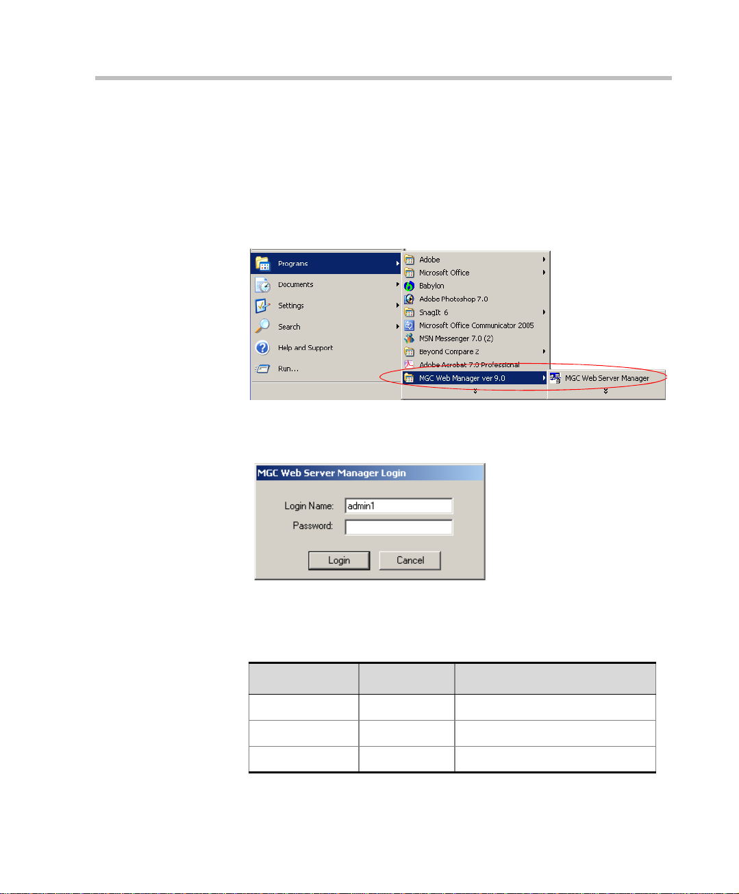
Starting the MGC Web Server Manager Application
To start the MGC Web Server Manager application:
1. On the Start – Programs menu, click MGC Web Manager ver 9.0, and
then click MGC Web Server Manager.
The Database Login dialog box opens.
2. Enter your Login Name and Password as defined in the database.
The MGC Web Server Manager is installed with the following default
login names and passwords:
Table 2-1: Default Users
User Name Password Permission Type
admin1 123 Administrator
oper1 123 Operator
user1 123 Moderator
2-3
Page 16
Chapter 2 - MGC Web Server Manager Basics
T able 2-1: Default Users
User Name Password Permission Type
user2 123 Moderator (Monitoring Only)
part1 123 Participant
These users differ in the functions they are allowed to perform and the
information they can access. For a detailed description of each of the
default permission types, see Chapter 4, Permissions.
When accessing the MGC Web Server Manager application for the first
time, it is recommended to log in as an administrator, to be able to define
various defaults, permissions and new users.
3. Click OK.
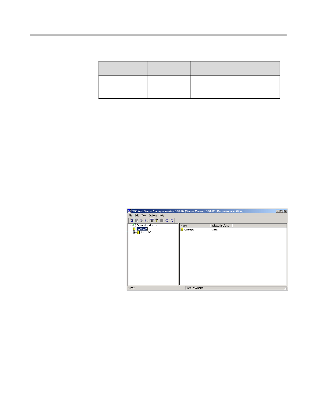
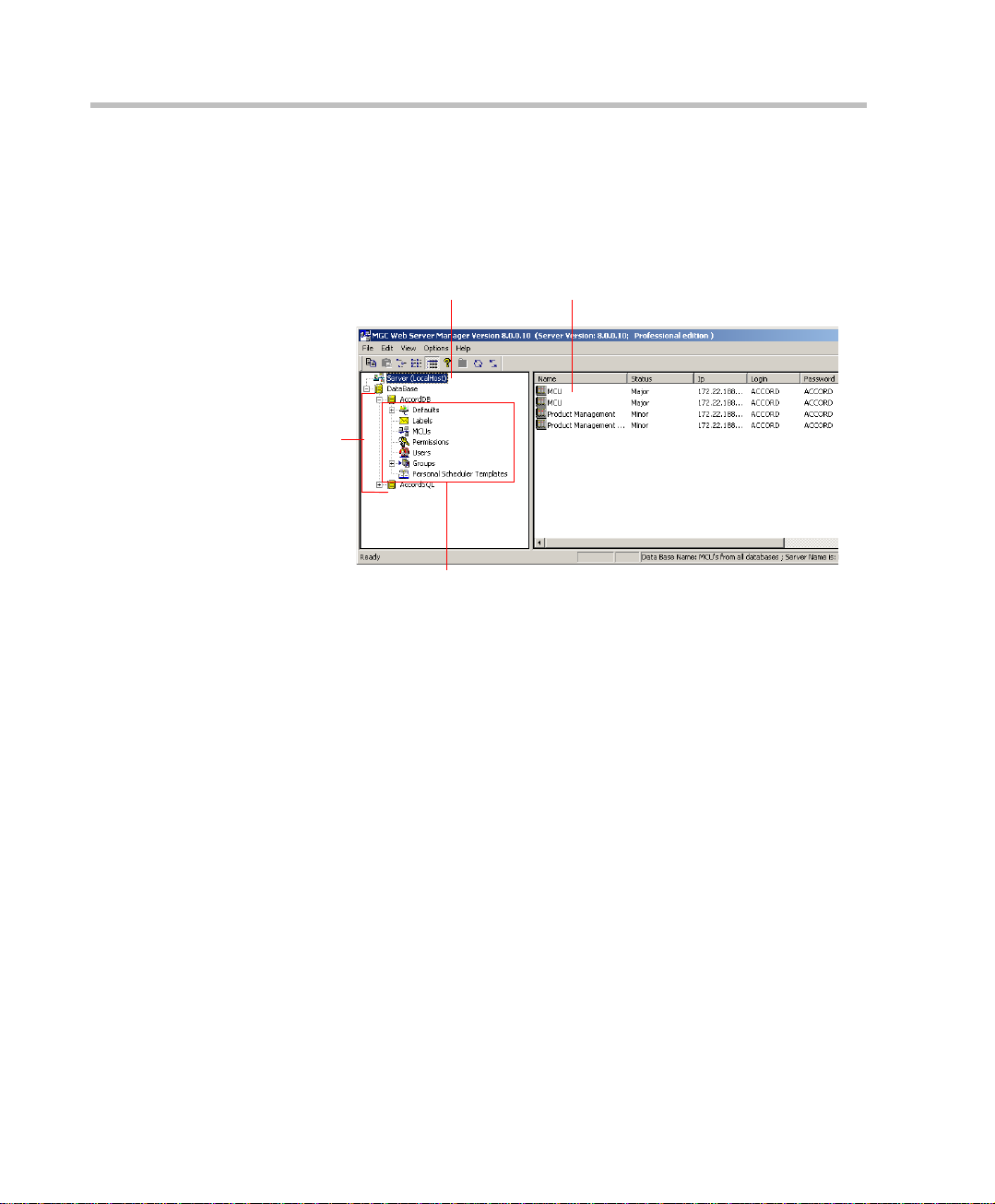
The MGC Web Server Manager window opens.
The MGC Web Server. The Web Server is
currently disconnected from MGC Web
Server Manager application
List of the
databases
registered in the
ODBC (even if
the database is
not registered in
the Web Server
Manager
Database)
2-4
Now you can add/modify entries in the various databases tables, such as
MCUs, Defaults, Groups, Permissions, Users, Master Groups and
Labels.
Page 17
MGC Web Server Manager User’s Guide
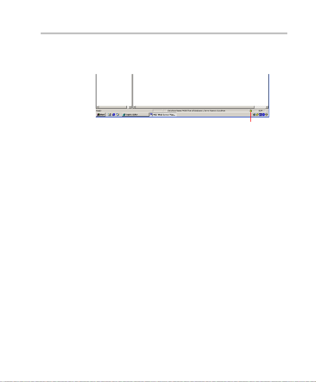
When Secure Mode is enabled for the WebCommander environment, the
Secure Mode is indicated by a lock icon that appears in the right corner
of the Status bar of the Web Server Manager application.
Secure Mode indication
To connect or disconnect MCUs to/from the MGC Web Server Manager
application you must first connect to the MGC Web Server. For more
information, see “Connecting to the MGC Web Server” on page 2-12.
2-5
Page 18
Chapter 2 - MGC Web Server Manager Basics
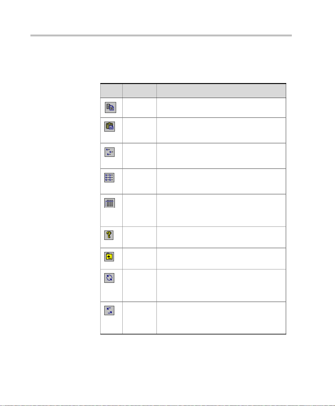
The Web Server Manager Toolbar
The following buttons appear in the Web Server Manager toolbar:
Icon Name Description
Copy Copies the selected record from a Web Server
Manager table to the clipboard.
Paste Pastes an entry from the clipboar d to the se lected
table. This option is enable d when the t able
category is selected in the Browser area.
Small
Icons
List Lists each of the table entries using a small icon
Details Click this button to show the det ails of each of the
Help Displays the About window indicating the version
Up one
level
Refresh
Database
List
Refresh
Database
Lists each of the table entries using a small icon
and the entry name. The list is displayed
horizontally.
and the entry name. The list is displayed
vertically.
table entries. The details are displayed in a table
format allowing you to sort the list according to a
selected column.
number of the Web Server Manager application.
Use to move one level up in the database tree.
Updates the databases list used by the system
when a datab as e was added to the OD BC li st v ia
the Control Panel and not from within the Web
Server Manager application.
Use to view changes that were made to the
database by other users, or via the MGC
Database manager, particularly when modifying
the Groups table.
2-6
Page 19
Upgrading from a Previous Version
When upgrading from a previous version of the MGC Web Server Manager,
the old database is saved during the installation procedure. If there are
discrepancies in the number of fields between the old and the new databases,
the system queries whether to update the existing database to the new format.
To upgrade the MGC Web Server Manager:
1. Start the MGC Web Server Manager application.
2. Log in as described in “Starting the MGC Web Server Manager
Application” on page 2-3.
When logging in the first t im e after the installation, the system prompts
you whether to update the databases installed in the system.
Windows 95/98 do not support Unicode, therefore when upgrading from a
previous version, the language tables will not be upgraded. In such a case,
perform the upgrade from a computer where Windows NT/2000 is installed.
3. Select Yes to automatically update the database (recommended), or No to
leave the database unchanged. If you select No, new entries to the
database via the MGC Web Server Manager will not be saved.
MGC Web Server Manager User’s Guide
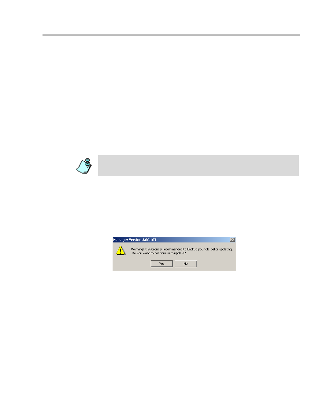
If you have selected Yes, a dialog box opens, informing you that it is
recommended to backup the database before updating them (as
precaution in case the update process fails for any reason).
4. (Optional) Backup the database. (The backup process is described in the
MGC WebCommander Release Notes document).
5. To continue with the update process, click Yes.
If you select No, the update process will be aborted and you will have to
restart once you are ready.
2-7
Page 20
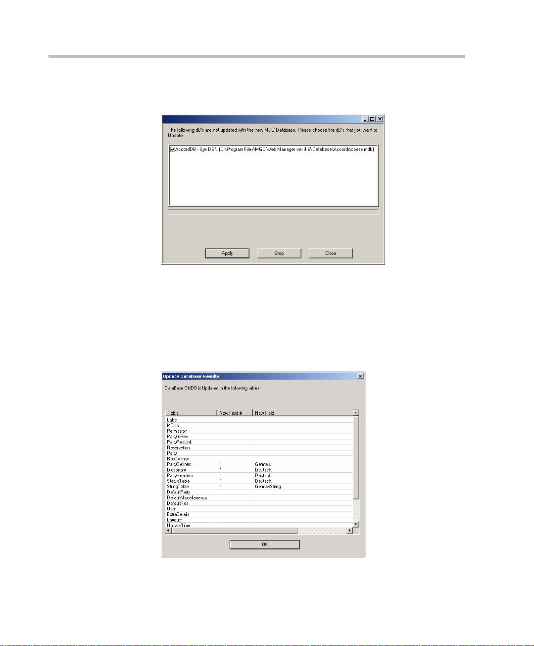
Chapter 2 - MGC Web Server Manager Basics
The Update Databases dialog box is displayed, indicating which
databases require updating.
It is recommended to update all the databases you intend to use.
To cancel the update of a database, clear the check box next to that
database name.
6. Click the Apply button to update the selected databases.
The updating process may take time, depending on the size of the
database. At the end of the process, the Update Database Results dialog
box opens, listing the fields that were updated.
2-8
Page 21

MGC Web Server Manager User’s Guide
The Update Database Results dialog box is displayed only in Windows 95/98
environment. It is not displayed when the Operating System is Windows 2000/
NT.
7. Click OK to return to the Update Databases dialog box.
When you open the MGC Web Server Manager for the first time after an
upgrade and you have not yet updated the database, you can do it later using
the Add/Remove Connection to the ODBC from the Options menu.
8. In the Update Database dialog box, click Close to exit the update
process.
2-9
Page 22
Chapter 2 - MGC Web Server Manager Basics
Displaying the Database Tables
In the MGC Web Server Manager window, click th e plus [+] icon next to the
icon of the database whose tables to display.
Browser Area
Database
Tables
These tables are displayed only when an
administrator is logged in
Status Area
The database tree is displayed. The tree categories, which represent the
database tables, change according to the permission assigned to the user who
logged into the database. If the user does not have a permission to read and
write all tables, the user will only be able to view and modify the Default
tables that s/he owns. Users with full access rights to the database
(administrators) will be able to view and add new entries to all database
tables. These tables can then be used by all the database users.
The following tables are available in the database tree:
• Defaults – Enables users to define conference, participant and general
system default parameters. In addition, you can define whether the User
Defined fields will ap pear in the M GC Manager and WebCommander
applications, and if yes, the titles of these fields in the MGC Manager
application. Users with permission to modify the database (Database
Configuration option is checked in the Permissions dialog box) ca n
define default settings to be used by all the MGC Web Server Manager
users. Users without the permission to modify the database tables can
define private default sets, for their exclusive use.
2-10
Page 23

MGC Web Server Manager User’s Guide
• Labels – Used to define labels. The labels may be assigned to
conferences and participants, mainly for sorting purposes. Only users
with the permission to configure the databa se may manage the La bels
table.
• MCUs – Enables the definition of MCUs that handle the multipoint
video conferencing. Only users with the permission to configure the
database m ay manage the MCUs list .
• Permissions – Used to define the access rights to var ious modules of the
MGC WebCommander and the MGC Web Server Manager applications
and perform various tasks. Only users with the permission to configure
the database may define or modify Permissions.
• Users – Enables the definition of the MGC WebCommander and the
MGC Web Server Manager users. Each user is assigned the appropriate
permissions, which defines his/her access rights to the system functions.
The User definition is also used for Ad Hoc conferencing when the
WebCommander is used as the external database for conference creat ion
and conference access au thentica tion. In addi tion it enabl es you to assi gn
access rights to the various groups defined in the Groups table. Only
users with the permission to configure the database may manage the
Users table.
• Groups – Enables the definition of groups to which users are assigned.
The conference templates and participant templates are also assigned to a
Group and can be viewed, modi fied, de leted or used to sta rt a confer ence
only by users who have access ri ght s to t hat Group . T he Group s enhance
the system security, giving the user access only to data that s/he is
allowed to view.
• Personal Scheduler Templates - Enables the definition of Personal
Scheduler Reservation Templates which are used by users of the MGC
Personal Scheduler application. The MGC Personal Scheduler
application is a pl ug-in to M icros oft Out look, enabli ng use rs t o sc hedule,
via Microsoft Outlook, conferences on the MCU in the same manner as
scheduling regular meetings.
2-11
Page 24
Chapter 2 - MGC Web Server Manager Basics
Connecting to the MGC Web Server
The MGC Web Server Manager application is the link between the MCUs
and the MGC Web Server. Therefore, the MGC Web Server Manager
application must first connect to the MGC Web Server before the connection
to the MCU may be in itiated.
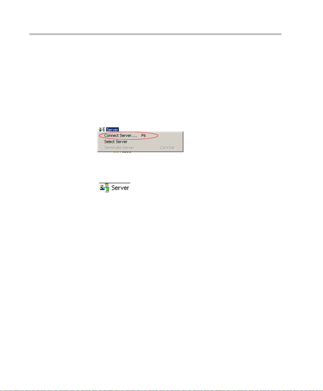
To connect to the Web Server:
1. In the Browser area, right-click the Server icon, and then click Connect
Server.
When the MGC Web Server is connected to the MGC Web Server
Manager application, the X is removed from the Server icon and a
blinking green LED indicates that the server is active.
2-12
Page 25
MGC Web Server Manager User’s Guide
Connecting/Disconnecting to/from an MCU
Once the MCUs are defined in the database, you can connect to an MCU.
This step is mandatory in order to run conferences, and it can be performed
only after the MGC We b Server Manager is connected to the MGC Web
Server. If all MCUs or the MGC Web Server are disconnected, remote users
cannot run conferences via the Web. For more details on how to define a new
MCU, see Chapter 5, “Defining an MCU” on page 5-1.
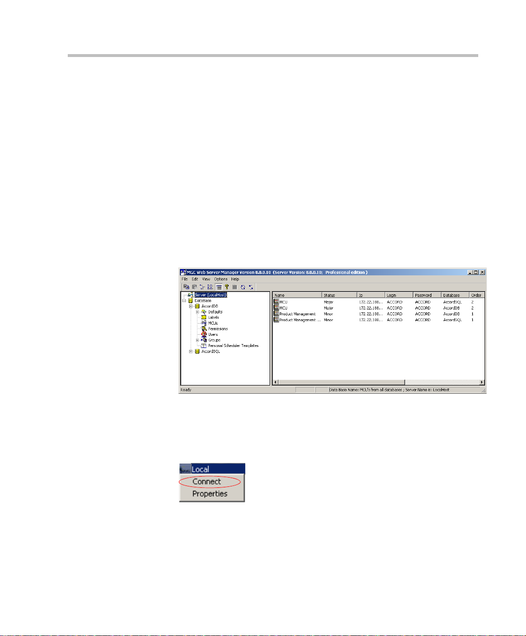
Connecting to an MCU
To connect to an MCU:
1. In the Browser area, click the Server icon to display the list of MCUs
currently defined in the MGC Web Server Manager application.
The MCUs list contains all the MCUs currently defined in all the
databases set in the Web Server Manager application. If the same MCU
is defined in two databas es, it will appear twice in the MCUs list.
2. In the Status area, right-click the MCU icon and then click Connect.
The system connects to the selected MCU. The MCU status that appears
in the Status area changes first to Connecting, during the connection
procedur e and then to Normal at the end of the connection procedure.
2-13
Page 26
Chapter 2 - MGC Web Server Manager Basics
MCU Statuses
The possible MCU statuses are described in the following table:
Table 2-2: MCU Status Options
Status Description
Connecting Connection in progress.
Normal The connection is OK and the MC U is in the Normal s t ate.
Start-up The connection is OK and the MCU is starting up.
Resetting
Low Memory The system has used up all its memory resource. In such
Bad Connection The connection betw e en th e MGC Manager and th e MC U
Major
Minor
Disconnecting from an MCU
To disconnect from an MCU:
1. In the Browser area, click the Server icon to display the list of M CUs
currently defined in the MGC Web Server Manager application.
2. Right-click the MCU icon and then click Disconnect.
The MCU is resetting.
a case, disconnect all running conferences and reset the
MCU.
is lost due to LAN problems.
A major error occurred, such as a c ard was re mo ved fro m
the MCU. Consult the system administrator.
A minor error occurred. Consult the system administrator.
2-14
The system disconnects the selected MCU and the MCU status that
appears in the Status area changes to Disconnected.
Page 27
MGC Web Server Manager User’s Guide
Setting the Communication Parameters
Sometimes there may be a communication problem between the Web Server
and the MCUs. One of the options to overcome this problem may be to
change the communication parameters between the MCUs and the Web
Server. Use discretion and consult your support engineer before modifying
these parameters.
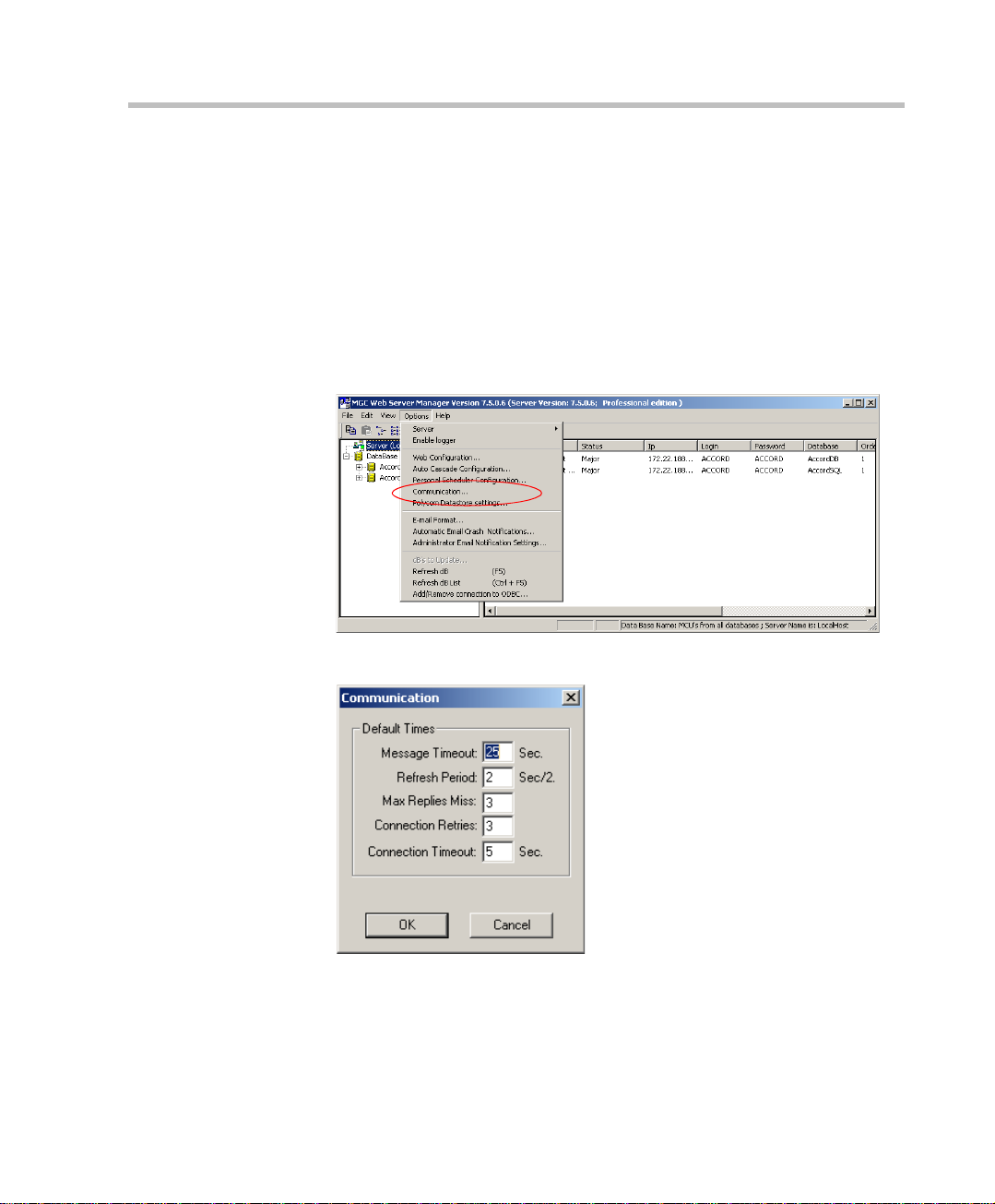
To modify the Communication parameters:
1. On the Options menu, click Communication.
The Communication dialog box opens.
2-15
Page 28

Chapter 2 - MGC Web Server Manager Basics
2. Define the following parameters:
Table 2-3: Communication Param et ers
Field Description
Message Timeout If no message is receiv ed from the M CU for the time
Refresh The frequency at which the MCU information in the
Max Replies Miss The number of messages that are sent and not
period specified in this field, an error is triggered.
Default value is 25 seconds. A higher value should
be entered when the connection is slow or all the
slots in the MCU are occupied. In these cases, the
recommended value is 120 seconds.
MGC Manager screen is updated. The refresh rate
is half of the seconds entered here. The default
value is 2, which means that the information is
refreshed every second (2/2=1).
received before a connection problem is triggered
and the system considers the connection as lost.
2-16
Connection
Retries
Connection
Timeout
3. Click OK.
The number of times the Web Server attempts to
establish a connection with an MCU following a
disconnection, or connection loss. Minimum value
should be 1.
The number of seconds the MGC Manager will wait
after each connection attempt for connection
confirmation. Default value is 5. If the connection is
slow, the recommended value is 25.
Page 29

Setting Default s
The MGC Web Server Manager applicat ion and MGC Manag er – Database
Manager application enable users to customize their system to their needs
by defining default values for reservations, participants and general system
parameters. The default sets may be stored in a centralized database or in a
local database.
When the WebCommander user defines a new conference (reservation, On
Going or a template) or a new participant, each parameters displays the
default value taken from the active Defaults set. It minimizes the need to
define all the parameters and it allows users to modify specific parameters,
as needed.
Default sets may be defined for the following categories:
• Conference Defaults – A list of all the conference parameters.
• Participant Defaults – A list of all the participant parameters.
• MGC Manager Defaults – General system parameters that apply only
to the MGC Manager. These parameters can also be defined in the
MGC Web Server if the same database is used by both applications.
• User Defined Fields – These paramet ers are u sed t o defin e whether t o
show the User Defined fields in the conference and participant
properties and the titles of these fields to be loaded in the MGC
Manager application.
3
The MGC Web Server Manager includes five default templates which are
stored in the Default Group. These templates are in addition to the
Reservation Defaults and enables end users to further automate the
conference scheduling process. For more details, see Chapter 5, “Defining
Groups” on page 5- 45.
3-1
Page 30
Chapter 3 - Setting Defaults
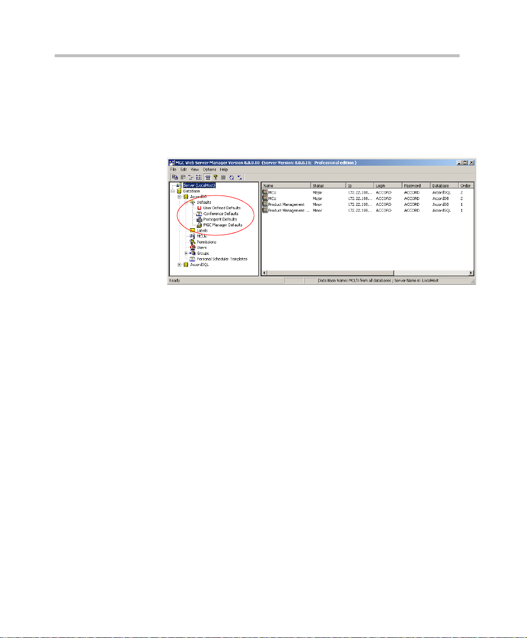
To display the defaults categories:
1. Once you are logged into the MGC Web Server Manager, click t he plus
2. Click the plus [+] icon next t o the Defaults icon to display the Defaults
[+] icon to expand the database tree.
categories.
3-2
Page 31

Defining Conference Defaults
The Conference Defaults are used to define the default values of new
conference templates created via the WebCommander application.
To define the Conference Defaults:
1. Right-click the Conference Defaults icon, and then click Add New
Conference Default.
The Conference Properties – Settings1 dialog box opens.
MGC Web Server Manager User’s Guide
2. In the Res Name box, enter the name of the Reservation Defaults set
being created.
3-3
Page 32

Chapter 3 - Setting Defaults
3. Define the following fields:
Table 3-1: Reservation Defaults - Settings1 Parameters
Option Description
Conf. Entry
Password
Web/Chairperson
Password
Numeric ID A Numeric ID is a unique number assigned to a
Enter a numeric password that will be used by the
conference participants to connect to the
conference.
It is recommended to leave this field blank to let
the WebCommander user to enter the password,
or MCU to automatically allocate a numeric
password.
Enter a numeric password that will be used by the
meeting organizer/chairperson to connect to the
conference (special privileges may be available to
the conference chairperson). The same password
is also used to view the conference properties
using the Web browser, once the conference is
started (in the Meeting Director module).
It is recommended to leave this field blank to let
the WebCommander user to enter the password,
or MCU to automatically allocate a numeric
password.
conference identifying it to the system. It can be
used by the partic ipant s to be routed a nd to access
the conference.
It is recommended to leave this field blank, to let
either the WebCommande r user or the MCU
assign one, otherwise, all conferences and Entry
Queues will the same default number, resulting in
error messages. If you assign a number, the MCU
cannot automatically assign one instead.
3-4
Billing The conference billing code as assigned to the
conference by your reservation system or
allocated to the conference chairperson o r c ontact
person.
It is recommended to leave th is field blank , to allow
the WebCommander user enter a unique billing
code during the conference initiation.
Page 33

MGC Web Server Manager User’s Guide
Table 3-1: Reservation Defaults - Settings1 Parameters (Continued)
Option Description
Remarks Using up to 300 characters, you may enter any
text regarding the conference. This text will be
included with the confere nce properties and is also
saved to the CDR file as part of the conference
record to be retrieved later.
Media Select whether the default co nfe rence is an Audio
only conference usi ng the V oi cePlus featur es or an
Video, Audio conference that may include both
audio only and video participants.
The selection of the media affects the availability
of options during the conference template
definition.
If Audio Look and Feel is configured in the Web
Configuration function, the Media is automatically
set to Audio.
Network Select whether the participants in the conference
use IP only or may different networks. When
selecting IP only, the Software CP option is
enabled in the Video Session box.
User Defined 1-3 The three User Defined fields enable you to enter
general information for the conference, such as
the company name, the contact person name, the
contact person’s E-mail or telephone number, or
any required information.
The titles of the User Defined fields can be
modified in the Database Manager -> Defaults ->
User Defined Defaults and loaded to the MGC
Manager application.
When starting a co nferenc e from the N ew Meeti ng
window you canno t define thes e fields (unles s they
were defined in the template used to start the new
conference), howeve r can define this information
during the On Going conference .
Notes:
• The User Def i ned fields are displayed only if
the Show User Defined Fields in Conference
Parameters box is selected in the Server
Manager -> Defaults ->User Defined Defaults.
3-5
Page 34

Chapter 3 - Setting Defaults
Table 3-1: Reservation Defaults - Settings1 Parameters (Continued)
Option Description
User Defined 1-3
(con’t)
Line Rate Specify the transfer rate in Kbps.
• If you have modified the titles of the User
Defined fields the new titles cannot be
displayed in the WebCommander application/
You can manually modify these titles in the
appropriate table (language) in the Access or
SQL database application.
In a Video Switching conference, you must select
the highest transfer rate common to all
participants. For example, if two part icipants can
connect at a transfer rate of 384 Kbps and one
participant can connect at a transfer rate of 128
Kbps, set the Line Rate to 2B or 128 Kbps (2B in
Bonding mode). In a conference with participants
from mixed networks (ISDN and H.323), the line
rate defined for the ISDN partic ipant is the line rat e
that will be used for the H .323 p a rtic ipant. The line
rate currently supported for H.323 is E1. In high
rates, the capacity of the H.323 Network card
changes. For more details, see the MGC
Hardware and Installation Guide, Chapter 4.
In Transcoding and Continuous Presence
conferences, the line ra te is defi ned for eac h of the
participants se parately. The conference line rat e
apply only to those participants whose Line Rate
was set to Auto. In such a case, set the conference
line rate to the highe st transfer r ate possible by the
endpoints connecting in Auto mode. Maximum
transfer rate in Transcoding and Continuous
Presence modes is 1920 Kbps (E1). In Software
Continuous Presence (SWCP) the Line Rate is set
for conferences and represents the transmission
rate from the MCU to the endpoint (combined
video rate and audio rate). For more details
regarding the Line Rate settings for Software CP
conferences, see MGC Manager User’s Guide
Volume II, Chapter 1.
3-6
Page 35

MGC Web Server Manager User’s Guide
Table 3-1: Reservation Defaults - Settings1 Parameters (Continued)
Option Description
Line Rate (con’t) Note: The high line rate transmission is enabled
with the standard vide o c ard (v ers io n 1 .43 an d u p)
or with the Video+ card. The line rate of incoming
ISDN/H.323 calls can be automatically detected
and the participant can be connected according to
his/her capabilities, without prior setting of the
endpoint’s line rate during conference setup. In
such a case, the conference Line Rate is the
maximum rate for the participant connection. For
more details, see MGC Manager User’s Guide
Volume II, Chapter 1.
Audio Alg Select the preferred audio al gorithm. The availa ble
audio algorithms are: 8 (G.729/G.723.1), 16
(G.728/Siren7), 24 (Siren14/G.722.1/Siren7), 32
(Siren14/G.722.1/Siren7), 48 (Siren14/G.722/
G.711), 56 (G.722/G.711), or 56 (G.711).
Siren 7 and Siren1 4 are Pol ycom prop riet ary audio
algorithms. Siren14 can be used only if the MCU is
configured to Wideband.
To support Siren14 , The system must include:
• The appropriate Polycom settings to support
Siren14.
• An Audio+ card must be installed in the MCU.
If the conference is set to Siren14 and the
endpoints cannot connect in Siren14, G.722.1 is
used instead.
The option 8 (G.729/G. 723.1) is available on ly in IP
Only (VOIP and video) conferences.
In Video Switching conferences, all of the
participants must use the same audio algorithm.
Participants with endpoints that do not supp ort th e
algorithm selected for the conference are
connected as Secondary (Audio only). If the
conference line rate is set to 2B or 128 Kbps, to
achieve the bes t audi o and vide o qual ity s elec t the
appropriate audio algorithm for all the participants
in the following order: G.728, G.722, G.711.
3-7
Page 36

Chapter 3 - Setting Defaults
Table 3-1: Reservation Defaults - Settings1 Parameters (Continued)
Option Description
Audio Alg (con’t) When Siren7 (16, 24 or 32 bit) is available, select
the audio algorithm in the following order: Siren 7
(16), G.728, G .72 2, G.71 1, Si ren7 16 bit and G.728
algorithms are interchangeable, and a participant
using either one will be fully connected when one
of them is selected as the audio algorithm.
If the conference li ne rate i s higher t han 12 8 Kbp s,
to achieve the best audio and video quality, select
the audio algorithm in the following order: G.722.1
(32), G.722.1 (24), G.722 / G711.
In Transcoding or Continuous Presence
conferences, you can set the audio algorithm to
any of the available audio al gorit hms as in a Vide o
Switching conference.
In Transcoding or Continuous Presence
conferences, you can set the audio algorithm to
any of the available audio al gorit hms as in a Vide o
Switching conference. If set to "Auto", the system
will try to connect the participants using the best
possible audio algorithm selecting it in the order
described for Video Switching conferences.
In Audio Only conferences , the default algorithm is
G.711 (56).
In a VOIP (Audio Only, IP Only) conference, you
can choose between the default G.711 (56) and
the G.729/G.723.1 (8) audio algorithm.
3-8
VTX1000 The VTX 1000 is a high quality, Wide Band PSTN
conference phone that can be used with the
Polycom MCU . During endpoint capabilities
exchanges a modem is used and the G.722.2
algorithm implemented. the VTX 1000 users are
allocated resources during the conference.
Select the checkbox when using VTX1000
endpoints.
Note: The system.cfg flag, VTX10 00=YES and the
Entry Queue must be enabled in the MGC
Manager.
Page 37

MGC Web Server Manager User’s Guide
Table 3-1: Reservation Defaults - Settings1 Parameters (Continued)
Option Description
Restricted Select this option if all the participants are using
Restricted lines whos e Line Rat e for ea ch chan nel
is 56 Kbps instead of 64 Kbps.
If not all the participant use restricted lines, the
Restrict option should be selected only in the
participant settings.
SilenceIT Select the Silence IT check box to enable this
feature. When a noisy line is detected and an
Audio participant is muted, a message is played,
informing the other participants that one of them
was muted due to the noisy line. Silence IT must
be enabled in the IVR Service to be enabled for
new conferences. If Silence IT is not enabled in
the IVR the conference definition is rejected.
Conference On
Port
Select the Conference On Port settin g, when you
want conferences to use a singl e vi deo port on the
MCU. It enables the selection of a video layout for
the conference, but all the conference participants
see the same layout and the same participants,
that is, also the speaker can see himself/herself.
Personal layout selection is not available in this
mode and the video quality is determined by the
highest common video parameters and video line
rate.
The following modes are not available for
conferences set to Conference On Port.
• Lecture Mode
• Personal Layout
• Cascading
For more information, see MGC WebCommander
User’s Guide, Chapter 7.
3-9
Page 38

Chapter 3 - Setting Defaults
Table 3-1: Reservation Defaults - Settings1 Parameters (Continued)
Option Description
T.120 Rate Select the desired T.120 data transfer rate. The
lower the rate the slower the transfer rate and the
response time.
The same T.120 rate must be set for all the
conference participants. The highest rate common
to all participants should be selected.
Select None to disable the T.120 mode.
If the conference Line Rate is set to 2B, the
following T.120 rates are available for selection:
• MLP - 6.4k
• MLP - 14.4k
• MLP - 16k
• MLP - 22.4k
• MLP - 24k
• MLP - 30.4k
• MLP - 32k
• MLP - 38.4k
• MLP - 40k
• MLP - 46.4k
• MLP - 14.4k
• MLP - 62.4k
Note:
Selecting a higher T.120 rate when the confe rence
Line Rate is 2B or 128 Kbps, results in a loss of
video quality.
If the conference is set to a higher Line Rate, the
following T.120 rates are available:
• HMLP - 64k
• HMLP - 128k
3-10
FECC/LSD Rate Using certain video cameras and their
accompanying software, a par ticipant may control
a far-end camera. This field is used to define the
LSD mode.
Page 39

MGC Web Server Manager User’s Guide
Table 3-1: Reservation Defaults - Settings1 Parameters (Continued)
Option Description
Video Session Sele ct the app ropriate Video Session:
Video Switching - To set a conference in which all
the participants use the same video and audio
formats, by setting the communication p aram eters
to the common capabilities. Whenever a
participant starts to speak, he/she appears on all
screens as the conference is a voice activated
video switching con ference. All participants view
the participant who is the speaker. Up to 16 or 30
participant s (if at least one Audio Brid ge i s set to 1/
30) can take part in a Video Switching conference
using the standard Audio card. Up to 100
participants a t 128Kbps can take part in a
conference running on the Audio+ card.
Transcoding - To set a conference in which
participants use different video, audio and data
formats, maintaining the highest video and audio
capability each particip ant can achiev e with his/her
codec. Like Video Switching, the current speaker
is displayed on all terminals.
3-11
Page 40

Chapter 3 - Setting Defaults
Table 3-1: Reservation Defaults - Settings1 Parameters (Continued)
Option Description
Video Session
(con’t)
Continuous Presence (CP) - A Continuous
Presence conference is a conference in which
several partici pants can be viewed simu ltaneous ly .
Each participant uses their own endpoint’s
capabilities, thus maintaining the highest video,
audio and data capability that can be achieved. If
the number of participants is less than or equal to
the number of participants displayed, each
participant can see all of the other participants.
When selecting Continuous Presence the
following layout options are available:
• Classic
• Quad Views
• Software
Classic - Classic Continuous Presence used the
standard Video card. 21 video layouts are
available in this mode.
Quad Views - The Quad Vie ws mode req uir es the
Video+ card. It includes layouts for large video
conferences. This mode should be selected when
the conference includes 10 par tic pants or more.
Software - Software Continuous Presence is
implemented in IP ne twork s onl y and is a soft w are
solution that resembles the Continuous Presence
feature in terms of functionality, without using
video card resources. Software CP combines four
incoming QCIF streams with fixed video bitrate
from four different participants into one outgoing
CIF stream. In Software CP conferences only two
types of Video Layout formats are available: 2x1
and 2x2. If the conference includes less than 5
participants, one of the participant's layout
windows is grayed out.
For more details , see MGC M anager Use r’s Guide
Volume II, Chapter 1.
3-12
Page 41

MGC Web Server Manager User’s Guide
Table 3-1: Reservation Defaults - Settings1 Parameters (Continued)
Option Description
Pro-Motion Pro-Motion is enabled only in the Video Switching
mode.
Pro-Motion is a video encoding mechanism that
improves the video quality in Video Switching
conferences, set to NTSC or PAL (4CIF)
resolution. Select either 50 Fields (PAL) or 60
Fields (NTSC).
Pro-Motion is sent t o th e e ndpoint at 60 Fields Per
Second (FPS) for NTSC and 50 FPS for PAL
systems. The interlaced video mechanism takes
two separate video frames and merges them into a
single frame.
Note:
When a conference is set to any Pro-Motion
option, endpoints sending a Pro-Motion video
resolution (for example, NTSC instead of PAL or
vice-versa) or that do not send a Pro-Motion
resolution, connect as Secondary (Audio Only).
3-13
Page 42

Chapter 3 - Setting Defaults
Table 3-1: Reservation Defaults - Settings1 Parameters (Continued)
Option Description
Dual Stream Mode In this mode, one of the endpoi nts s ends two v ideo
streams: Video and data. The video streams are
handled differently by the receiving endpoint. The
different streams may be shown on separate
screens.
Select one of the following options:
None - The Dual Video mode is unavailable. In
such a case Video Protocol is set to Auto.
H.239 and People+Content - H.239 and
People+Content are very similar in function, but
differ in the type of signaling us ed for each
protocol. People+Content is the Polyc om
proprietary protocol while H.239 is the industry
standard. When an endpoi nt can suppo rt both
H.239 and People+Content protocols, H.239 is
selected as the preferred communications
protocol.
In the Reservation Template Settings - Dual
Stream mode drop down box, three H.239
People+Content (H.239/P+C) Video streaming
formats are available:
Graphics - for standard graphics
Hi-res Graphics - for high qualit y disp lay or h ighly
detailed graphics
Live Video - for video clips or li v e video display
128 Kbps is the minimum Line Rate setting for a
H.239/People+Content conference. When the
Content channel opens, the required bit r ate is
taken from the video channel bit rate, and may
affect the quality of the transmitted video quality.
The bit rate allocated to the Content channel
depends on the conference type and the
conference line rate, where the minimum is
64 Kbps, and increases i n multiple of 64 Kbps. The
bite rate allocation is dynamic and when the
Content channel closes, the video bit rate is
restored to its maximum.
People+Content in a Cascading conference is
enabled only for Video Switching IP Only
conferences, in a Star Cascaded topology.
3-14
Page 43

MGC Web Server Manager User’s Guide
Table 3-1: Reservation Defaults - Settings1 Parameters (Continued)
Option Description
Dual Strea m Mode
(con’t)
H.239 and People+Content supports the following
features:
• Entry Queues
• Highest Common Phase 2
• H.264
• 4CIF
• Encryption
• FECC (H.320 and H.323)
Limitations
• In Continuous Presence conferences -
Software and Quad View modes are disabled
• H.239 is not supported in:
• ISDN (H.320) calls
• H.320 Cascading confe rences
• MIH Cascading conferences
• Simple cascading conf ere nc es
• T.120 conferences
• Double Gateway configurations
Using this feature the People video s tream an d the
Content video stream are treated differently by the
endpoints. For more information, see
WebCommander User Guide Chapter 7, “Dual
Stream Mode” on page 7-11.
People and Content V0 - Polycom proprietary
technology that works mainly with PictureTel
endpoints. Content, Annex N, Annex P and Annex
F are automatically checked by default.
DuoVideo - Dual Stream mode available with
T andberg endpoints in which one conference is set
as the video conference and the other as the
presentation conference. Select this option to
define the presentation conference.
Polycom Visual Concert PC/FX - Available with
Polycom Viewstation or Viewstati o n FX endpoints.
Select this option to enable the Visual Concert
option for the conference. Annexes can be
selected.
3-15
Page 44

Chapter 3 - Setting Defaults
Table 3-1: Reservation Defaults - Settings1 Parameters (Continued)
Option Description
Video Format CIF and QCIF are video formats used in video
conferencing systems. Video Format specifies the
data rate (in number of fr ames per seco nd) and
the resolution of each frame (number of lines in a
frame and the number of pixels in each line).
Video Format is enabled only in Video Switching
mode and when th e Video Protocol is set to H.261
or H.263.
CIF (Common Intermediate Format) - Each frame
contains 288 lines and 352 pixels per line. The
data rate is up to 30 frames per second (FPS)
QCIF (Quarter Common Intermediate Format) Each frame contains 144 lines and 176 pixels per
line (it is one-fourth the resolution of CIF).
This field is disabled if the Video Protocol field is
set to Auto.
• Using the H.261 protocol, you can selec t Auto ,
QCIF, or CIF.
Select Auto to allow the system to select the
video format for the conference according to
the partici pants' capabil ities and enable the
dynamic adjustment of the highest common
video reso lution. In such a case, the system
will connect all the participants in CIF format.
3-16
Page 45

MGC Web Server Manager User’s Guide
Table 3-1: Reservation Defaults - Settings1 Parameters (Continued)
Option Description
Video Format
(con’t)
If one of th e participants' endpoints does not
support CIF, the conference video format will
change to QCIF for all the participants.
• Using the H.263 protocol, you can select one
of the following options : Auto, QCIF, CIF, 4CIF,
16CIF, VGA, SVGA, XGA and NTSC.
4CIF - High Quality 4 CIF video reso lution ava ilable
in Continuous Presence conferences running at
512 Kbps or higher line rates. In this mode, the
endpoints t ransmit CI F (or QCIF) and rece ive 4CIF
images from the MCU. In full screen layout (1x1),
endpoints that can send 4CIF images will also
receive and view 4CIF images from the MCU.
In 4CIF CP conferences, you can select the
Quality of the screen display depending on the
video transmission:
Sharpness - Optimized for details. The video
picture does not change frequently, but it includes
details that you want to display in higher
resolution. For example, when displaying still
images, presentations, or capturing people.
Motion - Optimized for motion. The video pictures
change frequently and display movement, for
example, a sporting event where the camera is
moved around, people moving around, etc.
NTSC (National Television Standards Committee)
- Each frame contains 525 lines and up to 16
million colors.
VGA (Variable Graphics Array) - 640 x 480
resolution
SVGA (Super Variable Graphics Array) - 800 x 600
pixel resolution
XGA (eXtend ed Graphics Array) - 1024 x 768 pix el
resolution
VGA, SVGA, XGA and NTSC options are
important for displa ying conten t when sele cting the
People and Content mode. Typically the People
resolution is CIF with a frame rate of up to 30
frames per second, w hil e th e Con tent res ol uti on is
VGA, SVGA, XGA or NTSC.
3-17
Page 46

Chapter 3 - Setting Defaults
Table 3-1: Reservation Defaults - Settings1 Parameters (Continued)
Option Description
Frame Rate The Frame Rate is enabled only in Video
Switching mode and the V id eo Protocol is set to
H.261 or H.263. If you have selected QCIF, CIF,
4CIF, 16CIF, VGA, SVGA, XGA, or NTSC, select
the number of fram es per sec ond rate to defin e the
quality of the video transmission. 7.5 indicates a
video quality of lower than 30 frames per second.
Select Auto to enable the dynamic adjustment of
the conference frame rate to the highest common
rate.
This field is disabled if the Video Form at field is set
to Auto.
Video Protocol The Video Protocol, Video Format and QCIF
Frame Rate are parameters that determine the
highest common video used by all the conference
participants. The Video Protocol determ ine s the
video compression standard used by the
endpoints.
Auto - Select this option to let the system
automatically select the appropriate compression
method and enable the dy nam ic ad jus tm en t of the
highest common video algorithm. In such a case,
when a participant leaves the conference, the
MCU adjusts the common video to the highest
level for the remaining connected participants.
This setting overrides the Video Protocol se ttin g s
in the Participants Properties - Advanced dialog
box as the dynamic mode settings are forced by
the MCU.
H261 - The video compression standard
mandatory to all endpoints.
H263 - A compression standard that provides
improved video quality at a line rate lowe r than 384
Kbps. This standard is not supported by all
endpoints. If H.263 is selected in Video Switching
conferences, all participants must be connected
using this protocol. Participants whose endpoint
does not support H.263 are connected as
Secondary.
3-18
Page 47

MGC Web Server Manager User’s Guide
Table 3-1: Reservation Defaults - Settings1 Parameters (Continued)
Option Description
Video Protocol
(con’t)
H264* - H.264* incorporates DCT (H.263)
compression principles, but is provided at half the
bit rate. H.264* pro vi des C IF/ 4C IF vid eo us ing lo w
bit rates and implements a fixed video rate when
the video stream of the endpoint becomes active
("people "). The endpoint that supports H.264* is
iPower.
H264 - The H.264 standard provides better
compression of video images in lower line rate
connections and is part of the Highest Common
mechanism in Video Switching conferences.
When the conference line rate is up to 384Kbps,
and the Video Protocol i s set to Auto (in bo th VSW
and CP conferences) the system tries to connect
the participant using H.264 video protocol first.
Only if the endpoint does not support H.264, the
system tries to connec t the pa rticip ant using H. 263
or H.261.
When H.264 is selected, the Video Format is
disabled and set to Auto.
Notes:
• When selecting the H.261 or H.263, the system
regards it as a fixed format and disables the
dynamic adjustment of the highest common
video.
• The dynamic adjustment of the video protocol
applies only to H.320 (ISDN) participants.
The dynamic adjustment of the video protoc ol
supports only 30 frames per sec ond in CIF forma t.
All other H.263 capabilities are disabled.
3-19
Page 48

Chapter 3 - Setting Defaults
Table 3-1: Reservation Defaults - Settings1 Parameters (Continued)
Option Description
Annexes Annexes are additions to the Video Format when
using H.263 Video Protocol, increasing the quality
of the video display.
Annexes N, P and F are enabled only when you
are in Video Switching mode and the Video
Protocol is set to H.263. The Vide o Format ma y be
set to QCIF, CIF, 4CIF, 16CIF, VGA, SVGA, XGA,
or NTSC.
When Video Format is set to Auto, the system
selects the appropriate annexes according to the
endpoint's capabilities. The annexes are required
in the Dual Stream mode, but may also be
selected independently.
• Annex F - Advanced Prediction Mode. This
annex enables the transmitting encoder to use
four motion vectors fo r e ve ry m ac ro block (one
motion vector per block). A macro block is a
piece of the picture that contains four blocks.
Without this annex, the transmitting encoder
can only choose one motion vector for optimal
prediction of the macro block.
• Annex N - Reference Picture Selection Mode.
This annex enables the conference to recover
efficiently after transmission errors have
occurred in the macro bloc ks , an d repo rted via
a relevant message to the speaker encoder.
• Annex P - Reference Picture Re-sampling.
This annex enable s the tran smitting encoder to
apply a re-sampling process to the previous
decoded reference picture in ord er to genera te
a warped picture, for use in predicting the
current picture. The main purp ose of this annex
is to support the relationship of the current
picture to a previous picture, wh ich had a
different source format, such as CIF, QCIF,
4CIF, etc.
3-20
Page 49

MGC Web Server Manager User’s Guide
Table 3-1: Reservation Defaults - Settings1 Parameters (Continued)
Option Description
Chair Control Chair Control is an option that enables an endpoint
to control the conference and other conference
participants. This option is used to enable the
Chair Control. This option is enabled when the
Cascade field is set to None.
Cascade Cascade is an option that enables you to run a
conference that is connected directly to other
conferences (these conferences are not
connected directly to ea ch other). The co nferences
may run on different MCU’s or on the same MCU
(for large conferences that exceed the maximum
number of participants per conference). This
option is used to enable and select the cascading
mode.
Master Name When setting a Slave conference, the Cascading
option should b e se t to Slave, and the nam e of the
participant that acts as the link to the Master
conference is select ed from the Master drop-down
list.
3-21
Page 50

Chapter 3 - Setting Defaults
Table 3-1: Reservation Defaults - Settings1 Parameters (Continued)
Option Description
Roll Call Roll Call is a feature of the IVR Message Service
used to record the participants name and play it
back when entering and leaving a conf eren ce .
The chairperson can request the system to play
the names of all connected conference
participants at the beginning of the conference, or
at any time during the conference.
This option may be enabled only when the Roll
Call option is enabled in the IVR Service assigned
to the conference. When enabled for the
conference, the participant records his/her name
upon connection to the conference and the
chairperson may request a roll call in which the
recorded names of all conference participants are
played back to the conference.
If Entry Tone and Exit Tone are enabled for the
conference, participant name is played when the
participant enters or leaves the conference.
If Roll Call option is disabled for the conference bu t
enabled in the assigned IVR Service, the
participant name is recorded as the Roll Call may
be enabled during the on going conference , but roll
call cannot be requested.
3-22
Entry Tone Select this option to enable the Entry Tone, which
is played when a participant (audio or video)
connects to the conference. This tone is heard by
all the participants currently connected to the
conference (but not by the co nnect ing p artici pan t).
The tone is embedded in the MCU software.
Note: If Roll Call is enabled for the conf erence, the
Entry Tone is replaced by a playback of the
recorded participant name.
Page 51

MGC Web Server Manager User’s Guide
Table 3-1: Reservation Defaults - Settings1 Parameters (Continued)
Option Description
End Time Tone
n Min
Select this option to e nable the En d of C onferen ce
reminder tone to be played once, to all the
connecte d participants, n minutes before the end
of the conference. This tone is dif fe ren t from oth er
tones. The tone is embedded in the MCU's
software.
Note: If the automatic extension of the conference
is enabled for the MCU in the “confer.cfg” file,
selecting this option also enables the automatic
extension of the conference duration for this
conference. For more details see the MGC
Administrator’s Guide, Chapter 5.
Exit To ne Sele ct this op tio n to en able the Exit Tone, which is
heard by all the connected participants when a
participant leaves the conference. This tone is
different from other tones. It is embedded in the
MCU's software.
Note: If Roll Call is en abled for th e conferen ce, the
Entry Tone is replaced by a playback of the
recorded participant name.
3-23
Page 52

Chapter 3 - Setting Defaults
4. Click the Settings2 tab to display additional parameters.
3-24
The Attended and AV Msg Name fields change to IVR and IVR Msg
Name if Audio is selected as the Media in the Settings1 tab.
5. Define the following parameters:
Table 3-2: Reservation Defaults - Settings2 Parameters
Option Description
Attended Select one of the following options:
None - No Attended services are used during the
audio only conference.
Page 53

MGC Web Server Manager User’s Guide
Table 3-2: Reservation Defaults - Settings2 Parameters (Continued)
Option Description
Attended (cont.) Welcome (No Wait) - Sele ct this optio n for a Greet
& Guide conference in which the participant is
greeted by an audio message and after a predefined period, and automatically connects to the
appropriate conference.
Attended (Wait) - Sel ec t this opt ion for a att end ed
conference in which a participant is greeted by an
audio message, and then is assisted by the
operator who connects him/her to the appropriate
conference.
IVR - The IVR Service enables control over the
conference from the participant or chairperson
endpoint using touch-tone codes (DTMF).
Select this option to assign an IVR Service to the
conference. This option can only be selected if an
Audio+ card is installed on the MCU.
If the IVR Service check box is cleared and the
Entry Queue Access check box (in the General
tab) is checked, the participant connects to the
conference directly from the Entry Queue.
If both the IVR check box and the Entry Queue
Access check box (General Tab) are cleare d, dial in participants can only connect to the conference
once dialing the conference dial-in number (Meet
Me conference) or if they are defined prior to the
conference start. When you enable the IVR field
the following parameter check boxes become
available:
• Start Conf. Requires Chairperson
• Terminate After Chairperson Exits
• Enable Invite
• Roll Call
3-25
Page 54

Chapter 3 - Setting Defaults
Table 3-2: Reservation Defaults - Settings2 Parameters (Continued)
Option Description
AV Message
Name
Auto Termination Select this check box to automatically terminate
If you have selected the IVR Service in the
Attended field, type the nam e of the IVR Serv ice. If
left blank, the system uses the default IVR Service.
If you have selected a Welcome (No Wait) or
Attended conference, type the name of the AV
Service. The AV Service is defined in the MGC
Manager application. If left blank, the system uses
the default AV Message Service.
the conference by the MCU when:
• No participant has connecte d to the conferenc e
during a predefined time period
Or
• All the participant s ha ve di sc on nec ted from the
conference and the conference is idle for a
predefined time period
Before First Join x
Min
This option is enabled when the Auto Termination
option is selected.
Enter the number of minutes th at shou ld p ass from
the conference start time without any connected
participant, before the co nferenc e is consi dered as
idle. If no participant has joined the conference
during this period, it will be automatically
terminated by the MCU.
3-26
After Last Quit x
Min
This option is enabled when the Auto Termination
option is selected.
Enter the number of minutes th at shou ld p ass from
the time the last participant disconnected from the
conference, before the conference is considered
as idle. If the conferenc e remains idle and no other
participant joins in during this period, the
conference will be automatically terminated by the
MCU.
Page 55

MGC Web Server Manager User’s Guide
Table 3-2: Reservation Defaults - Settings2 Parameters (Continued)
Option Description
Entry Queue
Access
An Entry Queue is a spec ial rou ting lo bby q ueu e to
which one or more dial-in numbers are assigned.
When callers dial the assigned number, they
access a queue where they wait to be connec ted to
the conference. While waiting in the queue, they
hear the audio messages and prompts, and
interact with the system using touch-tone signal
(DTMF codes). The par ticipa nts ma y be connected
automatically to the conference if they have
provided the required conferen ce p as s word, or
they will wait for the Operator’s assistance if
enabled for the Entry Queue and if requested by
the caller.
Select this check box to force participants to
access the conference via an Entry Queue. When
selected, the partici pa nt must dia l the Entry Qu eue
dial-in number and enter the correct conferen ce
password in order to be transferred to this
conference.
Note: If this confe ren ce is also s et as Meet Me Per
Conf to which a separate dial-in number is
assigned, the participant can also connect directly
to the conference using this number.
To save the dial-in numb er, do not select Meet Me
Per Conf.
Meet Me Per Conf Select this check box to enable the Meet Me Per
Conference option. When selecting this option, the
Meet Me Per C onference tab appears.
The Meet Me Per Conference option allows
“undefined” parti cipan ts to c onnec t to a c onferen ce
by dialing a pre-defined conference number.
“Undefined” participants are participants that were
not defined prior to the conference start.
Auto Add This option is enabled when the Meet Me Per Conf
option is selected. It allows dial-in participants to
automatically connect to the appro priate
conferen ce, without prior setting of the participant
parameters.
3-27
Page 56

Chapter 3 - Setting Defaults
Table 3-2: Reservation Defaults - Settings2 Parameters (Continued)
Option Description
Min x Parties Available only when the Meet Me Per Conf. and
Auto Add options are checked. It lets you reserve
resources for the specified number of dial-in
participant s . Thi s n um ber i ncl ud es t he defined and
undefined participants. Additional participants
(defined and undefined) will be able to connect to
the conference as long as there are available
resources o r the Max Parties limit is met.
Max Parties This option is used to control the number of
participants that can connect to a conference.
Select the maximum number of participants that
can automatically con nect to the co nference. If y ou
select Auto, the number of participants that can
connect to the conference is limited only by the
availability of the MCU resources and the
maximum number of parti ci p an t s per co nference.
This option is useful in “Meet Me Per Conference”
with “Auto Add” participants.
3-28
Meeting Rooms Select this option to set the reservation as a
Meeting Room.
Limited
Sequences
This option is enabled when the Meeting Room
option is selecte d. Sele ct this check box to limi t the
number of times the Meeting Room will be
activated. When the check box is cleared, the
conference will rema in i n “s le ep m od e” i nde finitely,
and can always be activated. When this option is
selected, select the number of times the Meeting
Room can be activated. Entering 2 means that the
Meeting Room may be activated twice, but it will
remain passive during the period of inactivity.
Page 57

MGC Web Server Manager User’s Guide
Table 3-2: Reservation Defaults - Settings2 Parameters (Continued)
Option Description
Start Conf.
Requires
Chairperson
Terminate afte r
Chairperson Exits
Encryption Encryption is a process of disguising information
Select this check box to indicate that the
conference will only start when the Chairperson
connects to the confer ence. Participants that
connect to the conference before the chairperson
are placed on hold and hear background music.
Once the chairperson connects to the conference,
the participants are automatically connected t o the
conference.
When the check box is cleared, the conference
starts at its predefined time or when the first
participant connects to it.
Select this check box to automatically terminate
the conference once the conference Chairperson
disconnects from the conference.
into “ciphertext,” or dat a that will be unint elligi ble to
an unauthorized person attempting access to the
media.
In the WebComman der th e b eha vio r of t he s ys tem
at a conference and participant level is dependant
on MCU system.cfg flag settings set in the MGC
Manager.
In the Web Server Manager encryption must be
enabled in the Default -Conference Defaults by
selecting the Settings2 - Encryption box. In the
Participants Def aults - Settings2 you can select t he
appropriate Encryption default setting - Auto/On/
Off.
Encryption supports all types of audio and video
conferences including ISDN and IP participants.
The following guidelines apply to encryption:
• Encrypted can b e e nab le d a t the conference or
participants lev el
• Endpoints must support both AES 128
encryption and DH 1024 key-exchange
standards to encrypt and to join an encrypted
conference
3-29
Page 58

Chapter 3 - Setting Defaults
Table 3-2: Reservation Defaults - Settings2 Parameters (Continued)
Option Description
Encryption
(continued)
• Encrypted conferences with ISDN participants
require the installation of MUX+ card on the
MCU
• Encrypted conferences with IP participants
require the installation of IP+ card on the MCU
• The encryption feature supports all conference
types, including: Cascading, People and
Content, Operator, Meeting Rooms, Entry
Queues, and Ad Hoc conferences
• In a cascaded encrypted conference it is
important that the Link between the
conferences is encrypted
Talk Hold Time Indicate the minimum period, in seconds, that a
participant has to speak to become the main
speaker. During this period, no other participant is
allowed to become the main speaker. This
parameter is designed to preven t pa rtic ipants from
becoming the main speakers by coughing or
laughing, and to a void fast and frequent chan ges of
the main speakers.
Audio Mix Depth Indicate the num ber of the lou dest voic es speaking
at the same time that will be heard. The value 3
indicates that the three loudest participants
speaking at the same time will be heard.
3-30
Lecture Type Select the Lecture Modes from the drop-down list:
• None - Select this option to dis able the Lecture
Mode option.
• Lecture Mode - Enables the speaker to be
seen by al l other participants in full screen.
While the lecturer is speaking, the system
automatically switches between participants in
a predefined time interval, showing them
sequentially on his/her endpoint monitor.
Note: Lecture Mode is disabled when Same
Layout is selected.
Page 59

MGC Web Server Manager User’s Guide
Table 3-2: Reservation Defaults - Settings2 Parameters (Continued)
Option Description
Lecture Mode
(con’t.)
• Lecture Show - One-way communication
mode in which conference participants see and
hear the conference lecturer, however they are
not seen or heard by the lecturer (one way
communication).
Notes:
• Lecturer selection is mandatory at the
reservation stage and Lecture Show is
enabled only when one is selected. The
lecturer cannot be changed or deleted
during the On Going conference.
Full screen (1X1) format is the only video layout
that can be selected for Lecture Show.
• Presentation Mode - In Continuous Presence
conferences the syst em automatically display s
the active speaker full screen on all the
conference participant monitors while the
layout of the current speaker displays the
previous speaker of the conference. When
another particip a nt st a rts talking, the
Presentation M ode is cancell ed and conferenc e
returns to its predefined video layout.
In a COP conference, when the speaker
becomes the conference presenter, the
conference layout is automatically set to 1x1
(full screen) and all participants including the
active speaker view this layout.
• If the speaker is an Audio Only participant
(in a video conference), the Presentation
Mode is disabled for that participant.
• Video Forcing apply whil e the c onfere nce is
in normal speaker mode. When
Presentation Mode is activated, only the
lecturer can set the video forcing and it
applies only to the conference layout.
• During an On Going conference set to
Presentation Mode that is running on the
standard Video card, asymmetric conference
layouts are unavailable for selection.
3-31
Page 60

Chapter 3 - Setting Defaults
Table 3-2: Reservation Defaults - Settings2 Parameters (Continued)
Option Description
Lecture Mode
(con’t.)
Timer Select this check box to activate the automatic
Interval Enter the number of seconds a participant is
Lecturer Name Used to select the Lecturer name. This option is
Same Layout Select this check box to enable the Same Layout
• When a conference set to both Auto Layout
and Presentation Mode is run on the Standard
Video card, the definition of the layouts
selected for Auto Layout changes. For more
details, see MGC Administrators Guide,
Chapter 5.
switching of the participants displayed in the video
windows shown on the lecturer screen. It also
enables the Interval option.
displayed in the video window on the lecturer
monitor before switching to the next participant.
not applicable during the defaults definition.
feature.
Same Layout is a feature that “sets” and imposes
an identical video layout for all participants. During
the reservation stage, the moderator is able to
select a specific layout of his choice and apply the
selected layout settings to all conference
participants. It allows conference participants to
view his/her own video image.
When Same Layout is enabled during the
reservation stage, conference participants can
view his/her own vi deo im age to en sure th at ima ge
projection is of a reasonable quality (for example:
distance, focus, ligh tning, pos ture, and
presentation).
3-32
Page 61

MGC Web Server Manager User’s Guide
Table 3-2: Reservation Defaults - Settings2 Parameters (Continued)
Option Description
Auto Layout In Auto Layout the system automatically selects
the conference layout based on the number of
participants participating in the conference. With
Auto Layout, when a new video participant is
connected/disconnected, the conference layout
automatically changes format to refle ct the new
number of video participants. Audio Only
participants do not affect the selected layout.
• Software CP conferences cannot be set to Auto
Layout.
• The Auto Layout feature can be used with
Lecture Mode (for the lecturer display), but
cannot be enabled with Lecture Show.
• Auto Layout can be used with Same Layout
and Conference on Port (COP). In this mode,
the system selects the layout as if one
additional participant was added to the
conference to show the self view of the
speaker.
Owner The name of the user who has crea ted the Default s
set or to whom the administrator has assigned the
default set.
Duration Enter the conference length using the format
HH:MM. For example, to define a duration of 30
minutes, enter 0:30 and to enter the duration of 90
minutes, enter 01:30.
Dial-Out Manually Select this check box to designate an operator-
controlled dial-out conference connection. If DialOut Manually is checked, the operator monitoring
the conference need s t o m anu ally connect each o f
the participant s to th e confere nce. The parti cipan t s
remain on standby until the operator finishes
connecting all the participants to the conference,
otherwise, the partic ipant s will connect a t the same
time when the conference starts and becomes an
On Going conference.
3-33
Page 62

Chapter 3 - Setting Defaults
Table 3-2: Reservation Defaults - Settings2 Parameters (Continued)
Option Description
Lock Select this check box to lock the conference and
prevent dial-in participants from joining the
conference once t he co nferenc e has st arted. Clea r
this check box to unlock the conference and allow
dial-in participants to join the conference. A locked
conference can be unlocked during an On Going
conference.
On Hold Select this check box to place the conference on
hold when it is started.
When a conference is on hold, all participants hear
background music. When selected at the
reservation stage, o nce the confe rence is st arted, it
is automatically p laced on hold an d the partic ipant s
hear music upon connection to the conference.
A conference can be also be placed on hold and
released during an on going conference from the
Meeting Director window or by the chairperson
using the appropriate DTMF code from his/her
touch-tone telephone.
3-34
Mute “Meet Me”
Parties
Select this check box to mute undefined dial-in
“Meet Me” participants.
Once connected to the conference they are
automatically muted by the MCU to prevent
background noises until all the participants are
connected. In addition, if a lecture takes place it
assures that late arriva ls will no t disr upt the le cture.
The Mute “Meet Me” Parties option may be
disabled and enabled during the on going
conference (in the Meeting Director window) or via
the telephone using the appropriate DTMF code.
Enable Party Select this option to enable the Invite feature
during an on going Audio Only conference. It
enables the chairperson to request a line and dialout to invite participants to join the conference.
Page 63

MGC Web Server Manager User’s Guide
Table 3-2: Reservation Defaults - Settings2 Parameters (Continued)
Option Description
Background/
Layout Border/
Speaker Notation
Recording Enable Recording
Recording Link
Name
If the conference is handled by the Video+ card,
you can add visual effects such as borders and
colors, to the video layouts display on the
endpoints.
The following modification options are available:
• Background color - the color displayed when a
video layout is empty. This may happen when
the video layout contains more windows than
connected participants.
• Layout Border - the borders frame of each
window in the video layout. The thickness of
the border is fixed.
• Speaker Indicatio n - you can use a different
color for the border to highlight the window of
the current speaker.
Enables the recording of audio in a audio or video
conferen ce by an exter nal recorder. The setting in
the Default Reservation/ Start Recording define
when the conference recorder is activated when
the conference is On Going.
Select this check box to enable the conference
recorder.
The name of a recording link defined in the MGC
Manager.
Start Re cording Select one of the following settings for activa ting
the a recorder:
• Immediately
• Upon Request
When set to Immediately the first participant to
enter the conference, activates the conference
recorder.
When Upon Request is the selected default the
conference chairperson or the Operator can
manual activate the conference recorder fro m the
On Going Conference recording pane. For more
information see
3-35
Page 64

Chapter 3 - Setting Defaults
6. Click OK to confirm and store the new Conference Defaults set.
Defining Participant Defaults
The Participant Defaults are used to define the default va lu es of pa rameters
in the new participant templates created in the WebCommander application.
To define the Participant Defaults:
1. Right-click the Participant Default icon, and then click Add
Participant Defaults.
The Party Properties -Settin gs1 dialog box opens.
3-36
2. In the Name box, enter the name of the participant defaults set.
Page 65

MGC Web Server Manager User’s Guide
3. Define the following parameters:
Table 3-3: Participant Defaults - Settings1 Parameters
Option Description
Name En ter the participant’s name using numerals and
characters only. You must give each participant a
distinct name.
Interface Type Select the Interface Type. Select ISDN if the
participant c onnect s via ISDN li nes, T1-CAS if t he
participant connects via T1-CAS lines, ATM if the
participant i s using the ATM network, H.323 or SIP
if the participant is connected via LAN, and MPI if
the participant is connected via serial connection.
Note: SIP participan t s req uire th e IP+ c ard se ries,
hardware version 4.24 or above.
Connection Type Select the app ropr iate connection type from the
drop-down list.
The MGC WebCommander allows you to set up
conference dialing according to three connection
types:
Dial-in - The participant phones the MCU at
conference time. You inform the participant of the
MCU’s phone num ber . When se lecting this o ption,
the Meet Me Per options are enabled.
Do not select this option if your default
participant’s connection type is T1-CAS as only
undefined T1-CAS participants can connect to
conferences.
Dial-out - The MCU calls the participant at
conference time. The participant’s phone number
may be entered later, when setting up the
conference.
If the Manual Dial Out option in the Schedule tab
of the conference settings is cleared, the MCU
automatically calls the participant at conference
time. If this option is checked, the operator calls
the participant.
Direct - T he pa rticip ant s are c onnect ed direc tly to
the MCU through an ISDN leased line. No dialing
is required for direct connections.
3-37
Page 66

Chapter 3 - Setting Defaults
Table 3-3: Participant Defaults - Settings1 Parameters (Continued)
Option Description
Participant Phone
Numbers
This field applies to the ISDN/T1-CAS, Dial-out
connection type, or to ISDN, Dial-in Meet Me Per
MCU option (when selected). Type the
participant’ s phone number (i ncludin g country an d
area codes when required) to be dialed by the
operator when connecting the participant to the
conference. Add a semicolon (;) between
numbers when several numbers are to be
assigned to a participant. For example,
92511111;9251112;….;xxxx.
If the Meet Me Per MCU option is selected, type
the phone number by which the participant is
identified (CLI number). This number is used by
the MCU to route the caller to the appropriate
conference.
MCU Numbers This field applies only to the ISDN, Dial-in, Meet
Me per MCU-Conference connection type. Enter
the phone number the participant should dial to
connect to the MCU.
If left blank, the MCU automatically assigns a dialin number (from the lis t of dia l i n n umbers defined
in the Network Service) when the conference
starts.
Participant
Bonding
This field applies only to the ISDN, Dial-out
connection type, and should be used only if
Bonding is the selected Aggregation type for the
participant.
Enter a single number for all the aggregated
channels. The system will automatically assign
the appropriate phone numbers to the remaining
channels.
If left blank, the MCU automatically assigns the
first number that appears in the Partic ipa nt Phone
Number field when the conference starts.
3-38
Page 67

MGC Web Server Manager User’s Guide
Table 3-3: Participant Defaults - Settings1 Parameters (Continued)
Option Description
Meet me per This field applies only to the ISDN, Dial-in
connection type.
Party - The particip an t di als a u ni que dia l n um ber
for each group of channels he will use.
Channel - The participant dials a different dial
number for each channel.
MCU – A single phone number is assigned to all
the conferences running on a certain MCU. The
MCU phone number is entered in the Network
Service – Span and Phones dialog box.
The participants are routed to the appropriate
conferences according to their ph one numbers
(CLI) which are entered in the Participant Phon e
Numbers. When a participant dials in to the
conference using the MCU number, the PBX
identifies the originating party number and routes
the participant to the appropriate conference
accordingly.
This option should be used only with PBXs
supporting the CLI (Caller ID) option.
User Defined 1-4 There are 4 User Defined fields that en able you t o
enter general information for the participant, such
as the participant’s: E-mail address, telephone
number , comp an y n ame, lo catio n, or any requi red
information.
The titles of the User Defined fields can be
modified in the Database Manager/Web Server
Manager-> Defaults -> User De fined Def ault s and
can be loaded only to the MGC Manager
application.
Note: The User Defined fields are displayed only
if the Show User Defined Fields in Participant
Parameters box is selected in the Web Ser ver
Manager -> Defaults ->User Defined Defaults.
3-39
Page 68

Chapter 3 - Setting Defaults
Table 3-3: Participant Defaults - Settings1 Parameters (Continued)
Option Description
User Identifier
String sent to the
Recording system
Enter the string sent to the Recording System via
DTMF codes that identifies the recording. This
identifier string is used later by the user
connecting to the con ference rec order We b site to
identify the recording and retrieve it.
You need a unique User Identifier String for each
recording. The User Identifi er Stri ng can consist of
one of the following options:
• a series of numbers. In such a case all the
recordings will have the same number
assigned to them
• n - Enter n to as sign the co nference Nu meric
ID or the Conference password to the
recording as the identifying stri ng .
• l - Enter i to assign the conference
Chairperson password to the recording as the
identifying string.
• b - Enter b to assign the conference billing
code to the recording as the identifying string.
Volume Select the volume in which the participant’s audio
is transmitted to the conference. The volume
scale is from 1 to 10, where 1 is the weakest and
10 is the strongest. The volume of each endpoint
at the time of connection is 5. One movement of
the volume slider incre ases or decreases the
volume by one unit. Each un it is equ ivale nt to 3db.
3-40
Listening Volume Select the volume in which the conference audio
is heard by the participant. The volume scale is
from 1 to 10, whe re 1 is the weakes t a nd 1 0 i s th e
strongest. The volume of each endpoint at the
time of connection is 5. One movement of the
volume slider increases or decreases the volume
by one unit. Each unit is equivalent to 3db.
Page 69

MGC Web Server Manager User’s Guide
Table 3-3: Participant Defaults - Settings1 Parameters (Continued)
Option Description
Owner Displays the name of the us er to whom the defau lt
set is assigned. This field is disabled for users
without permission to modify (write) database
tables. Users with Administrator rights (that can
read and write database tables) can assign the
defaults se t to any registered user. The Owner
name may be used for filtering.
VIP Click this check box to designate the participant
as VIP. This status is used to indicate (an icon)
participants who need special attention during the
conference.
4. Click the Settings2 tab to display addi tional parameters .
The Party Pro perties – Settings2 dialog box opens.
3-41
Page 70

Chapter 3 - Setting Defaults
5. Define the following parameters:
Table 3-4: Participant Defaults - Settings2 parameters
Option Description
Aggregation This fi eld appli es to ISDN c onnections only. Select
the aggregation method:
H221 – The standard communication protocol, in
which a different phone number is assigned to
each channel.
Bonding - A communication protocol that
aggregates from two up to thirty 64-kbps B
channels together t o look li ke one la rge bandw idth
channel.
Multi-Rate – A communication protocol in which
channels are aggregated to form one dedicated
line. The MGC Manager currently su pports
aggregation of 6 channels to form one line of 384Kbps rate (64 X 6=384). In such a case, the
network ensures that all six chann els are
synchronized and there are no intervals between
the arrivals of the da ta packets.
Auto – Click this option to connect the participant
according to his/he r capabiliti es. When con necting
to the conference, the endpoint and the MCU
exchange capabilities. During this exchange, the
MCU identifies the aggregation mode used by the
endpoint and connects it accordingly.
3-42
Number of
Channels
This field applies only to ISDN/ATM connections.
Indicate the number of channels the pa r ticipant
uses for the connection.
Select “auto” to use the conference’s Line Rate
setting. This is also the mode recommended for
ATM conferences.
Select the appropriate number of channels to
force the system to use the participant settings.
Page 71

MGC Web Server Manager User’s Guide
Table 3-4: Participant Defaults - Settings2 parameters (Continued)
Option Description
Video Protocol Select the Video compress io n standard:
H261 – The video compression standard
mandatory to all codecs.
H263 - A compression standard that provides
improved video quality at a line rate lower than
384 Kbps. This standard is not supported by all
codecs.
Auto - select this option t o use the con ference’s
Video Protocol settings.
Voice This field applies to ISD N and H.323 connections .
Select Data for dat a, audio an d video tra nsmission
(using the H.221 protocol).
For audio only transmission, select Voice. This
option is automatically selected for T1-CAS
participants.
Recording You can designate one participant designated as a
recording port (that is, a telephone to which a
recording device may be connected). The
recording port is used to record the audio
conference.
Select None for a standard participant.
Select Dial-up to designate this participant as a
recording port.
Auto Detect This field appl ies only to ISDN connectio ns. Check
this option to enable th e automatic detec tion of the
line rate of incoming ISDN calls by the MGC
WebCommander and connect the participant
accordingly without prior settings of the line rate
during conference setup. The participant can be
connected in a line rate of up to the line rate set for
the conference.
3-43
Page 72

Chapter 3 - Setting Defaults
Table 3-4: Participant Defaults - Settings2 parameters (Continued)
Option Description
Enhanced Video The MGC Manager can provide hig h q ual ity v ide o
(30 frames per second for incoming and outgoing
video streams) for line rates up to T1/ E1 in
Transcoding and Continuous Presence
conferences. This is done by allocating two video
codecs to the participant instead of one. One of
the video codecs is used for encoding, while the
other is used for decoding the incoming video
stream.
Select this check box to enable the high quality
video feature for th e participant .
Note:
• To work with 30 frames per second the High
Frame Rate flag in the system.cfg must be
enabled.
• To work with bit rates higher than 768 Kbps,
the High Bit Rate flag in the system.cfg must
be enabled.
3-44
AGC The Auto Gain Control (AGC) is the system
default.
Clear this check box to disable the Auto Gain
Control (AGC) for the participant.
The Auto Gain Control mechanism regulates
noise and audio volume by keeping the received
signal to all participants balanced. Different
endpoints and phones produce different types of
source noise and volume. The Auto Gain Control
mechanism can be applied to all incoming audio
streams prior to mixing, thereby dynamically
changing the amplification of the input signal
providing a constant output amplitude.
Page 73

MGC Web Server Manager User’s Guide
Table 3-4: Participant Defaults - Settings2 parameters (Continued)
Option Description
Encryption In the Participants Defaults - Settings2 you can
select the appropriate Encryption default setting -
Auto/On/Off.
Choose any of the following Encryption options:
• Auto - When participants connect to a
conference, the conference/Entry Queue
encryption settings are automatically applied
to the participant. For example, when a
conference/Entry Queue is set to encryption
the participant is also encrypted (if the flag in
the MGC Manager
ALLOW_ENCRYPT_IN_PARTY_LEVEL is set
to YES).
• On - enables encryption at the participant
level (if the flag MGC Manager
ALLOW_ENCRYPT_IN_PARTY_LEVEL is set
to YES).
• Off - disables encryption
Note: Undefined participants are connected with
the Participant Encryption option set to Auto,
inheriting the Conferenc e/En try Qu eue encryption
setting.
Restrict Only This field appl ies only to ISDN c onnections. Select
this check box if the participant is using a
restricted line whose transfer rate per channel is
56 Kbps (instead of 64 Kbps). This option is valid
for a Transcoding or Continuous Presence
conference only.
H323 Participant Participant IP
Address
H323 Participant Signaling Port
H323 Participant Alias Name
Enter th e default IP address for endpoints.
This field should not be mod ified unle ss a dif ferent
signaling port was configured during installation
and connection to the network.
Select the participant’s alias type and then enter
the alias of the endpoint.
3-45
Page 74

Chapter 3 - Setting Defaults
Table 3-4: Participant Defaults - Settings2 parameters (Continued)
Option Description
H323 Participant Alias Type
SIP Address
SIP Address
Type
Select the format of the alias from the drop down
list. Only E.164 and H.323 ID are supported.
sip: [user name]@[domain].
Note that the SIP URI adheres to URI rules: no
spaces or special characters such as commas,
quotation marks, inverted tags and so forth either
in the user name or in the domain part.
[To compare to H.323, which uses the endpoint location
for identifying the participant, in SIP participants can
change locations but still be addressed as long as they
continuously refresh their registrations with the proxy.
The proxy forwards invitees to their current location.
SIP URI: A SIP URI uses the format of an email
address, typically containing a username and a
host name, sip:user@host. For example,
sip:dan@polycom.com.
TEL URL: "Tel" means that a voice call is op ene d.
TEL URL may be used when the UA does not
wish to specify the domain that should interpret a
telephone number that has bee n input by the user .
Rather, each domain through which the request
passes would be given that opportunity. As an
example, a user in an airp ort might log in and send
requests through an outbo und proxy in the airport.
If they enter "411" (this is the phone number for
local directory assistance in the United States),
that needs to be in terp reted and processed b y the
outbound proxy in the ai rport , not the user's home
domain. In this case, tel:411 would be the right
choice.
3-46
H323 Participant Video Bit Rate
KBits/sec
This option is enabled if the Auto Video Bit Rate
option is cleared. It allows you to specify the
specific video transfer rate (multiples of 100 bits/
sec is recommended) for the participants. This
option defaults to the conference setting when
adding a new participant during an On Going
conference.
Page 75

MGC Web Server Manager User’s Guide
Table 3-4: Participant Defaults - Settings2 parameters (Continued)
Option Description
H323 Participant Auto Video Bit
Select this option to use the video transfer rate
defined for the conference.
Rate
Enable PSTN Dial-inPSTN participants are able dial-in into an H.323
Meet Me Per Conference using the ISDN MeetMe Service number. For example, by calling
9251437, the ISDN’s Meet-Me Service number, a
3G cellular phone PSTN participant can connect
as a H.323 dial-in participant to the Meet Me Per
Conference.
However, when the participant dials the IP service
prefix using the gatekeeper he/she can enter the
Numeric ID (NID), conference name, or Meet Me
Per Conference ISDN number and connect as an
H.323 video participant.
Service Name Type the nam e of the parti cipant’ s service pro vider
exactly as it is defined in the Network Ser v ice
function (the system is case se nsi tiv e).
If left blank, the default Network Service is used,
depending on the select ed C onnection Type. If the
selected Connection Type is ISDN, the default
ISDN Network Service is used. If the selected
Connection Type is H323, the default H323
Network Service is used.
Sub-Service Name This field applies only to ISDN connections.
If a sub-service is used, type the sub-service
name exactly as i t appe ars in the Network Service
definition.
If left blank, the default sub-service is used.
Node Type This option is always set to Terminal.
3-47
Page 76

Chapter 3 - Setting Defaults
6. Click OK to confirm the new set.
Table 3-4: Participant Defaults - Settings2 parameters (Continued)
Option Description
Num-type This field applies only to ISDN connections.
Select the program type from the drop-down list.
The available options are Unknown, National,
International, Network Specific, Subscriber,
abbreviation and Taken from Service. These
options represent the programs provided by the
carrier and are defined in the Network Service.
Select Taken from Service to indicate that the
program should be taken from the Network
Service definition.
3-48
Page 77

MGC Web Server Manager User’s Guide
Defining MGC Manager Defaults
To define the MGC Manager Defaults:
1. Right-click the MGC Manager Defaults icon, and then click Add
MGC Manager Defaults.
The MGC Manager Defaults dialog box opens.
2. In the Name box, enter the name of the defaults set.
3. The Owner field displays the name of the user to which the default set
is assigned. This field is disabled for users with no permission to
modify (write) database tables. Users with Administrator permission
(can read and write all da tabase tables) can assign the defaults set to
any registered user.
4. Define the following parameters:
Table 3-5: MGC Manager Defaults parameters
Option Description
General Defaults Save Participant – When enabled, the Save
Participant checkbox will appear in the Participant
Properties dialog box enabling the user to save
the participant properties to a User Template file.
3-49
Page 78

Chapter 3 - Setting Defaults
Table 3-5: MGC Manager Defaults parameters (Continued)
Option Description
General Defaults
(cont.)
Conference
Templates in DB
Linked Party – When enabled, the Linked Party
checkbox will appear in the Particip ant Properties
dialog box enabling the user to save the
participant properties to the database. When
disabled, participants defined during conference
definition will be embedded participants only. For
more details regarding linked and embedded
participants, refer to Chapter 3 of the MGC User’s
Guide.
Linked Party Message – When enabled, the
system will display a warning message when
closing the Properties dialog box of a linked
participant without saving the parameters to the
database.
Show Time in DB Conference Templates –
When enabled, the system will display the
Schedule tab in the Properties dia log box of a
Conference template defined in the dat abase. Th is
enables the user to add the time that the
conference should start. This option may later be
used to filter conferences that should start on a
specific day. Note that this date and time are not
used to automatically st art the conference from the
database template on the scheduled date.
Show Past Time as Current Time – When
enabled, the system will autom ati cal ly updat e the
start date and time of an existing Conference
template to the current date (even if the original
start date and time are in the past). Note that when
filtering conferences according to the start date
and time, the conference will retain the past date
and time unless it is updated. This option is
enabled only when the Show Time in DB
Conference Templates check box is checked.
3-50
Page 79

User Defined Defaults
You can select whether to display the User Defined fields in the conference
and participant properties dialog boxes in the MGC Manager and the
WebCommander applications .
You can define the titles of the User Defined fields. These titles replace the
default titles (User Defined 1, 2 and 3) when the Database Manager
Defaults are loaded to the MGC Manager application. These titles do not
appear in the WebCommander unless they were modified directly in the
Language database (via the database application; Microsoft Access or
SQL).
The User Defined fields are saved to the CDR file using the default names.
The new titles that you define in the Database Manager -> User Defined
Defaults are for display purposes only.
To define the User Defined Defaults:
1. Expand the Defaults tree, right-click the User Defined Defaults icon,
and then click the Add User Defined Default.
MGC Web Server Manager User’s Guide
3-51
Page 80

Chapter 3 - Setting Defaults
The User Defined dialog box opens.
3-52
2. Define the following parameters:
Table 3-6: User Defined parameters description
Field Description
Name Enter the name of the User Defined default set.
Owner Enter the name of the owner of this set. Only the
owner and the administrator with the appropriate
permission will be able to modify this set.
Leave this field blank to a ssign this set to the curren t
logged in user.
Page 81

MGC Web Server Manager User’s Guide
Table 3-6: User Defined parameters description (Continued)
Field Description
Show
Reservations User
Defined Fields
Select this check box to display the User Defined
fields in the Conference Properties - General dialog
box. If you clear this check box, all three User
Defined fields will be hidden.
Show Participants
User Defined
Fields
Select this check box to display the User Defined
fields in the Participant Properties - Identification
dialog box. If you clear this check box, all four User
Defined fields will be hidden.
Reservation Titles User Defined 1, 2 and 3 - using up to 25 characters
enter the text to be displayed as the title of the User
Defined fields in the Conference Properties -
General dialog box. These titles replace the default
titles (User Defined 1, etc.) If left blank, the default
titles are displayed.
Note: The titles of the User Defined fields appear
only in the MGC Manager application. In the
WebCommander application, only the default titles
are shown.
Participant Titles User Defined 1, 2 and 3 - using up to 25 characters
enter the text to be displayed as the title of the User
Defined fields in the Participant Properties -
Identification dialog box. These titles replace the
default titles (User Defined 1, etc.) If left blank, the
default titles are displayed.
Note: The titles of the User Defined fields appear
only in the MGC Manager application. In the
WebCommander application, only the default titles
are shown.
3-53
Page 82

Chapter 3 - Setting Defaults
3. Click OK.
You can define several sets. All the sets are considered to be personal sets
which only you can us e. If you hav e ad ministrator rights you can designate one
set as a public set. Thi s set m ay be lo aded to the MGC Manager ap pl ica tio n by
all the Web Server Manager and Database Manager users.
The new User Defined Defaults set is added to the list.
3-54
Page 83

Managing the Default Sets
The MGC Web Server Manager application is installed with an embedded
Defaults set. If no Defaults set is defin e d as the Global Defaults set, the
embedded Defaults set is active.
A Defaults set may be set as Private o r Global Defaults. A Global Defaults
set is a default set that will apply to all the database users. A Private
Defaults set applies only to users wh om it is specifically allocated a s the
Private Defaults set, and is used instead of the Global Defaults set.
The administrator can select one of the default sets defined in the database
as the Global Defaults set. However , the datab ase users can also define on e
of their default sets as Private Defaults set. In such a case, the user will be
able to use this set instead of the Global Default set.
Only one Defaults set may be defined as Private Defaults set. Selecting
another Defaults set as Private Defaults Set automatically cancels the
current Private Set. One set may be defined as both Global and Private
Defaults set.
The selection of the Global and Private Default set is done separately for
each Defaults category.
If more than one database is i nstal le d, the syst em loads t he P rivate d efaul ts
from the database designated as Private and the Global Defaults from the
database designated as Global. Therefore you must define the database
from which you want to load the Private Defaults set as Private and the
database from which you want to load the Glob al defaul t set as Gl obal. You
may define the same database as both Global and Private. In that case, the
Global Defaults set and the Private Defaults set will be taken from the same
database.
You can also designate a database as Private Default and another database
as Global Default. When a user loads the Global o r the Pr ivate defau lts, it i s
loaded from either the Private or Global Default database according to the
selected Default set. For example, if you select to load the Private Default
set, it will be loaded from th e database designated as the Private Defaults
database.
Using the right-click pop-up menu you can also delete a default set or
change the default set parameters.
MGC Web Server Manager User’s Guide
3-55
Page 84

Chapter 3 - Setting Defaults
To define Default set as Private set:
• In the Status area, right-click the icon of the Default s set, and then click
Set As Private Default.
The appropriate indi cat i on a ppear s in the Status area an d a check mark
appears next to the Set As Private Default option.
Defining a Default Set as Global Defaults Set
Only the administrator can define a set as Global default.
To define a Default set as Global:
• In the Status area, right-click the Defaults set icon, and then click Set
As Global Default.
3-56
The appropriate indi cat i on a ppear s in the Status area and a check mark
appears next to the Set As Global Default option.
Page 85

Assigning a Default Set to other Users
Only the administrator can assign default sets to other participants.
To assign a Default set to other users:
1. In the Status area, right-click the icon of the default set to be assigned
to other participants, and th en click Set Default to Users.
The Add Default to Users dialog box opens.
MGC Web Server Manager User’s Guide
The system displays the list of users currently defined in the database.
2. Select the check boxes of the users to which to assign the default set.
To select all users, click the Select All button.
3. Click OK.
The appropriate indication appears in the Status area.
3-57
Page 86

Chapter 3 - Setting Defaults
Designating a Database as the Private or Global Default Database
Only the administrator can assign a Private or Global Default Database.
1. In the Browser area, right-click the database icon to be designated as
the Private or Global Default database.
A pop-up menu appears.
2. Click Set As Private Default to designate this database as the source
for the Private Default set, or click Set As Global Default to designate
this database as the source for the Global Default set.
3. A check mark next to the selected option indicates which option is
active.
To define the database as both Private and Global, select both options
repeating steps 1 and 2.
Default Conference Templates
Five Conference templates, representing each of the main types of
conferences, are included the Default Group in the database th at is shipped
with the WebCommander. The parameters defined in each of these
conferences represent the most commonly used properties for the specific
type of conference.
For more information about Default Conference templates, see Chapter 5,
“Default Group” on page 5-50.
3-58
Page 87

Options Settings
In the Web Server Manager Options menu, the following topics are listed:
• Web Configuration - For further information, see the MGC Web
Manager, Installation and Configuration Guide, Chapter 5.
• Auto Cascade Configuration - see “Auto Cascade” on page 4-2.
• Redundancy Configuration
• Backup Configuration
• Personal Scheduler Config urat ion - For further information, see the
MGC Personal Scheduler, Quick Start Guide, Chapter 2.
• Communication - For further information, see Setting the
Communication Para m eters in Chapter 2 of this manual.
• Polycom Datastore Settings - For furth e r information, see the MGC
Web Manager, Installation and Configuration Guide, Chapter 5.
• Automatic Email Format - see Customize e-mail settings.
• Automatic Email Cras h Notifications - see Send Debugging
information to your next level of support.
• Administrator Email Notification Settings - see Send an e mail to the
administrator after an Reservation, New Meeting or Conference is
created.
4
4-1
Page 88

Chapter 4 - Options Settings
Auto Cascade
The Auto Cascade feature enables automatic cascading of conferences. Both
audio only and video conferences can be cascaded.
The automatic cascading of conferences is beneficial in distributed MCU
environment, when MCUs are installed in different locations. A maximum of
six conferences can be Auto Cascaded into one conference. The MCU
network can support multiple Auto Cascaded conferences simultaneously.
Auto Cascading Mechanisms
The Ad Hoc Cascade is part of the Central Server Service that is installed as
part of the MGC Web Server Professional installation. The Central Server
Service monitors all the MCUs that are defined and connected in the MGC
Web Server Manager. When two or more MCUs are running a conference
with the same Conference Numeric ID, the Central Server Service checks if
the conferences are already cascaded. If there are no connected cascading
links, it will automatically connect the conferences using pre-defined
cascading links. If at a later stage an additional MCU running a conference
with the same Numeric ID is identified, it will add this conference to the
cascaded conferences.
The links between the MCUs and other configuration parameters are defined
using the MGC Web Server Manager. A primary link is defined between each
pair of MCUs to be included in the Auto Cascade. A secondary link can
optionally be defined for use as a backup if the primary link fails.
4-2
Selection of the Master Conference
The conferences are cascaded in a star configuration - one master and up to
five slaves. The master conference is selected when cascading first takes
place between two or more conferences.
If chairperson activation is enabled in the Auto Cascade configuration in the
MGC Web Server Manager, then the master conference is determined as
follows:
• If one of the conferences has a participant who is defined as a
chairperson, and none of the other conferences has a chairperson, the
conference with the chairperson will be assigned as the master
conference.
Page 89

• If none of the conferences has a chairperson, then the conference that is
running on the MCU which is highest in the MCUs table in the Web
Server Manager will be assigned as the master conference.
• If there is more than one conference with a chairperson, then the
conference with a chairperson that is running on the MCU which is
highest in the MCUs table in the Web Server Manager will be assigned
as the master conference.
If chairperson activation is disabled, then the conference that is running on
the MCU which is highest in t he MCUs tabl e in the Web Server Manager will
be assigned as the master conference.
Chairperson Activation
If chairperson activation is enabled in the Auto Cascade configuration in the
MGC Web Server Manager, then the cascaded conference can implement the
“Start when the chairperson connects”, and “Terminate conference after the
chairperson exits” features, provided these options are selected in the
individual conferences.
Starting the Conference to be Cascaded
If the “Start only when the chairperson connects” option is implemented,
participants in all conferences will be placed on hold until a chairperson joins
one of the conferences.
Terminating a Cascading Conference
If the “Terminate conference after the chairperson exits” option is
implemented, all conferences will be terminated when there is no longer a
chairperson connected to a conference. In addition, the system will terminate
a slave conference when it no longer has any live participants, and will
terminate the master conference when no participants are connected and no
slave conferences with connected participants are still connected to it.
Implementation of Chairperson DTMF features
The following chairperson DTMF actions are implemented across the MCUs:
• Mute all but me
• Terminate the conference
• Place the conference on hold
• Lock and unlock the conference
• Secure the conference and release a secured conference
4-3
Page 90

Chapter 4 - Options Settings
Auto Cascading Guidelines
• To enable the Auto Ca scading, the Conference Numeric ID routing mode
is required, therefore the system.cfg flag
IVR section
NO on all MCUs.
• H.239/People + Content is not supported with Auto Cascading.
• The Auto Cascade feature can only be implemented for the database
assigned as the Global Default in the Web Server Manager. To assign a
database as the Global Default, right-click on the database and select the
Set as Global defa ult option.
• The MGC Manager and WebCommander monitoring is per MCU,
therefore cascaded conferences are monitored as separate conferences
and not as one large conference
• Operator assistance is per MCU.
• The following chairperson actions are not implemented across MCUs:
Voting, Question and Answers, Replay Roll Call, Change password.
• All the MCUs must have IVR/DTMF licenses.
• In Continuous Presence conferences, the layout must be set to full
screen.
• For H.263 4CIF and H.264 Continuous Presence conferences, the link
will be defined as H.263 CIF.
- QUICK_LOGIN_VIA_ENTRY_QUEUE must be set to
in the GREET AND GUIDE/
Auto Cascade Configuration
The configuration of the Auto C ascading environmen t invo lves conf igura tion
in both the MGC Web Server Manager and in the MGC Manager application.
MGC WebCommander Professional installation is required. You are required to
install and configure the WebCommander and Web Server Manager application.
On the MGC Manager you are required to configure the Entry Queue for Ad Hoc
Cascading.
• In the MGC Web Server Manager application, define the properties of
Cascading Links between the MCUs in the Auto Cascade configuration
table.
4-4
Page 91

• In the MGC Manager application, for each MCU define an Ad Hoc Auto
Cascade Entry Queue. The cascaded link is established when one MCU
dials the connection string of the Entry Queue defined on the second
MCU followed by the Conference Numeric ID. Calls to Auto Cascade
Entry Queues will be considered as MCU calls and no IVR will be
played.
For more information refer to the MGC Manager User’s Guide Volume
II, Ad Hoc Cascading.
It is recommended to set up identical Ad Hoc Ent ry Queu es and Pro files on each
MCU, so that the cascaded conferences will have the same properties.
Configuring the Cascading Links using the Web Server Manager
The Web Server Manager is used to set up the properties of the primary and
optionally, the secondary links between MCU’s.
Before con figuring the Cascading Links, you must define all the MCUs that will
be included in the Auto Cascading environment.
To Configure the MCU Cascade Links:
1. In the main W eb Server Manag er window , sel ect the database assigned as
the Global Default.
2. On the Options menu, click Auto Cascade Configuration.
4-5
Page 92

Chapter 4 - Options Settings
3. Select the Enable Cascade Links check box.
The Cascade Links List dialog box opens.
4-6
When enabled, the system displays the list of primary and secondary
links between each two MCUs defined in the MCUs table of the Web
Server Manager.
Page 93

4. Define the cascaded link parameters for the primary lin ks, and option ally
for the secondary links. For each cascaded link define the following
parameters:
Table 4-1: Cascaded Link Paramete rs
Column Description
Link Priority Indicates whether this row contains a primary or
secondary link definition.
Source MCU The name and IP address of the first MCU.
Direction Contains an icon indicating the dialing direction of the
link between the MCUs, as follows:
The destin ation MCU dials to the source MCU.
The source MCU dials to the destination MCU.
Click the icon to reverse the link direction.
Destination MCU The name and IP address of the second MCU.
Network Type Select the type of the network to be used to connect the
two MCUs from the list: ISDN, IP (H.323), MPI, SIP or
T1-CAS.
Connection String Enter the string that will be used to connect to the Auto
Cascade Entry Queue on the second MCU as follows:
• For ISDN and MPI, specify the Entry Queue dial-in
number.
• For H.323 and SIP specify the Network Service
Prefix followed by the Entry Queue Numeric ID.
5. In the Redial At te mpts field, specify the number of attempts to recon nect
to the destination Auto Cascade Entry Queue when the connection fails.
6. Select the Chairperson Activation check box to enable the chairperson
features “start only when the chairperson connects” and “terminate
conference after the chairperson exits” in Auto Cascaded conferences.
7. Click OK.
4-7
Page 94

Chapter 4 - Options Settings
MCU Redundancy
The Central Server Service is designed to monitor th e activity of assigned
pairs of MCUs, so if one MCU in th e pai r enc ount er s a p robl em t hat prevents
it from running conferences, the other MCU will take over smoothly.
In Central Server Service environment, as described in Figure 4-1, MCU A
and MCU B are both registered in the gatekeeper with the same prefix and
they are designated as backup to each other in the WebCommander Central
Server Service.
The Central Server Service monitors both MCUs. When a new on going
conference is created on one MCU (for examp le, MCU A), th e Central S erver
Service automatically copies this conference to the second MCU (for
example, MCU B) with the prefix *bck_. In the same way, when new
reservations and Meeting Rooms are created on one MCU they are
automatically copied to the second MCU.
Gatekeeper
MCU A Prefix - 70
MCU B Prefix - 70
Conferences list
Meeting Rooms list
Reservations list
Primary MCU (A)
MCU Prefix in GK - 70
On Going Conference abc
Figure 4-1: Central Server Service Environment
WebCommander
(central server)
Routes the calls from MCU A to MCU B
PBX (ISDN)
Backup MCU (B)
MCU Prefix in GK - 70
On Going Conference *bck_abc
4-8
Page 95

When one MCU is down (for example, power shortage), the gatekeeper will
identify that one MCU (A) is unavailable and will automatically forward the
calls to the second MCU (B). The participants are connected to the
conference that was copied from MCU A with the same name.
When the first MCU (A) is up and running again, the gatekeeper will connect
the participants to conferences running on MCU A. If a conference with the
same ID is now running on both MCUs (for example, if MCU A recovered
quickly, participants that connected later were connected to MCU A), the
system will automatically cascade both conferences (using the Auto Cascade
feature) to create one conference. This will eliminate the need to disconnect
and reconnect participants to a single conference.
If the origin conference i s ter minated o n one MCU its ba ckup conferen ce will
be automatically terminated on the second MCU.
In the same way, if ISDN PBX is configured to route calls from one MCU to
another according to MCU availability, the same behavior will occur.
The Central Server Service is disabled in Secure Mode.
Redundancy Guidelines
• ISDN and IP Network Services must have the same configuration (for
example, MCU Prefix in gatekeeper , dial -in numbers range, etc.) on both
MCUs.
• Conference Profiles, Entry Queue and IVR Services must be iden tical on
both MCUs.
• Entry Queues must be identical on both MCUs.
• The following conference parameters are copied from the source MCU
to the target MCU (backup):
— Conference duration
— Passwords (chairperson and conference entry)
— User Defined fields
— Billing Code
— Lecture Mode parameters
— Layout and Auto Layout
4-9
Page 96

Chapter 4 - Options Settings
• The following conference parameters are NOT copied:
• If a new conference is started or scheduled on one MCU, and the MCU
• Defined participants are not copied between MCUs and they must be
• If the conference is cascaded, it cannot be monitored as one conference.
• If the parameters of one con ference are updated, they w ill be
• The CDR files are separate on each MCU. A backup conference is
When MCU Redunda ncy i s ena bled, do not enter d ata in th e f ield “Us er Defin ed
3” as it is reserved for the Central Server Service intern al use .
— Remarks and Remarks History
— Lecturer Name (as the backup conference does not include
participants)
— Video Forcing (as the backup conference does not include
participants)
failed before the conference was backed up on the second MCU, this
conference will not be backed up.
added manually to the backup conferences.
automatically updated also in the backup conference.
identified by its prefix and when activated it will contain participants.
MCU Redundancy Configuration
1. Click Start-Programs > MGC Web Manager ver 9.0 > MGC Web
Server Manager.
The Login window is displayed.
2. Enter your User Name and Password and click OK.
MGC Web Server Manager window opens .
3. If required, add new MCUs to the list.
4. On the Options menu, click Redundancy Configurat ion.
The system displays a list of paired MCUs currently defined in the Web
Server Manager.
4-10
Page 97

5. Select the MCU pair(s) that you want to use to backup each other.
6. Click OK.
From this point on, all conferences, Meetin g Room and Reservations wi ll
be mirrored between the MCUs in the select pairs.
4-11
Page 98

Chapter 4 - Options Settings
MCU Backup
The Central Server Servic e enables you t o schedule automati c system backu p
of selected MCUs. The automatic backup includes:
• System configuration (including Network Services and IVR Services)
• Meeting Rooms
• Reservations
• Conference Profiles
• Entry Queues
Defining the Backup Parameters
The backup interval and target path are defined once. It is important to
connect the WebCommander Server and MCUs prior to the definition of the
backup parameters as the first backup is performed when the definition is
completed.
To define the Backup parameters:
1. Click Start-Programs > MGC Web Manager ver 9.0 > MGC Web
Server Manager.
The Login window is displayed.
4-12
2. Enter your User Name and Password and click OK.
MGC Web Server Manager window opens .
3. If required, right click the Server icon and then click Connect Server.
4. If required, add new MCUs to the list and connect them to the server.
5. On the Options menu, click Backup Configuration.
The Backup configuration dialog box is displayed.
Page 99

6. Select the Interval in which the backups will be performed.
7. In the Target Path, click the Browse button to select the destination disk/
folder where the backed up files will be stored.
8. Click OK.
The system automatically performs the first backup of all the connected
MCU.
The information is saved to the selected target path (disk), creating a
folder whose name is derived from the MCU IP address. For each
backup, the system creates a folder with t he suf fix _generation _n where
n is the backup number and in which the dat, cfg and msg folders are
stored. If the backup fails for any reason (for example, if the MCUs are
not connected or the WebCommander server is not active), the suffix
Corrupted is added to the backup folder name in the format _generation
_n_corrupted.
4-13
Page 100

Chapter 4 - Options Settings
Automatic Email Language Formatting
In the MGC W eb Server Manager you can customize the language and defau lt
email format of a new Meeting, configuring the email settings for the
WebCommander and Personal Scheduler.
You can customize the language and the text of the e-mail sent t o p artici pan ts
with the conference invitation. The customization applies to Meeting
invitations sent from the WebCommander and Personal Scheduler.
To change the format of an email:
1. In the MGC Web Server Manager, Options menu, sele ct E- mail Format.
4-14
 Loading...