

Page 1

MGC
Administrator’s Guide
Version 7.5
Page 2

Copyright © 2006 Polycom, Inc.
All Rights Res erved
Catalog No. DOC2067F
Version 7.5
Proprietary and Confidential
The information contained herein is the sole intellectual property of Polycom, Inc. No distribution, reproduction or unauthorized
use of these materials is permitted without the expressed written consent of Polycom, Inc. Information contained herein is subject
to change without not ic e and does not represent comm it m ent of any type on the part of Polycom, Inc. Polycom and Accord are
registered trademarks of Polycom , In c.
Notice
While reasonable effort was made to ensure that the information in this document was complete and accurate at the time of
printing, Polycom, Inc. can not assum e responsibility for any errors. Ch anges and/or corrections to the i nformation contained in
this document may be inc orporated into future issu es.
Page 3

Canadian Department of Communications (EC) Declaration of Conformity
Polycom, Inc. declares th at the MGC-50/MGC-100 wit h N ET-8 card is in conformity with the following relevant harmoniz ed
standards:
EN 60950: 1992 Including Amendments 1,2,3 & 4
EN 55022: 1994
EN 50082: 1997
and follows the provisions of the Council Directive 1999/EC on radio and telecom m uni cation terminal equipment and the
recognition of its conformity.
Notice: The Industry Canada label identifies certified equipment. This certification means that the equipment meets
telecommunication network protective, operational and safety requirements as prescribed in the appropriate Terminal Equipment
Technical Requirements document(s). The D ep art ment does not guarantee the e qui pment will operate to the use r's satisfaction.
Before installing this equipment, users should ensure that it is permissible to be connected to the facilities of the local
telecommunications company. The equipment must also be installed using an acceptable method of connection. The customer
should be aware that com pliance with the above conditions may not prevent deg radation of service in some situa ti ons.
Repairs to certified equipment malfunctions, may give the telecommunica tions company cause to requ est the user to disconnect
the equipment.
Users should ensure for their ow n protection that the electrical ground connections of the power utility, telephone lines and
internal metallic water pipe system, if present, are connected together. This precaution may be particularly important in rural
areas.
Caution: Users should not atte mpt to make such connections themselves, but should conta ct the appropriate ele ctr ic in sp ec tion
authority, or electrician, as appropriate.
Page 4

Page 5

Table of Contents
Before You Begin . . . . . . . . . . . . . . . . . . . . . . . . . . . . . . . . . . 1-1
Scope of Manual . . . . . . . . . . . . . . . . . . . . . . . . . . . . . . . . . . . . . . . . . . . .1-1
Contents . . . . . . . . . . . . . . . . . . . . . . . . . . . . . . . . . . . . . . . . . . . . . . . . . . .1-2
Conventions . . . . . . . . . . . . . . . . . . . . . . . . . . . . . . . . . . . . . . . . . . . . . . . .1-4
List of Abbreviations . . . . . . . . . . . . . . . . . . . . . . . . . . . . . . . . . . . . . . . . .1-5
Installation and Configuration Workflow . . . . . . . . . . . . . . . . . . . . . . . . .1-6
Software Installation . . . . . . . . . . . . . . . . . . . . . . . . . . . . . . . . 2-1
MGC Manager Software Installation . . . . . . . . . . . . . . . . . . . . . . . . . . . .2-2
First Entry IP Configuration . . . . . . . . . . . . . . . . . . . . . . . . . . . . . . . . . . .2-7
MCU Definition . . . . . . . . . . . . . . . . . . . . . . . . . . . . . . . . . . . . . . . . . . . . .2-7
Defining a Secured (SSL) Connection to the MCU . . . . . . . . . . . .2-10
Viewing the MCU Connection Type in the MGC Manager
Application . . . . . . . . . . . . . . . . . . . . . . . . . . . . . . . . . . . . . . . .2-16
MGC Configuration - Setting the MCU Date and Time . . . . . . . . . . . . .2-17
Modifying the MCU Local Time for Daylight Savings . . . . . . . . .2-20
MGC Unit Software Installation . . . . . . . . . . . . . . . . . . . . . . . . . . . . . . .2-21
Dongle Information . . . . . . . . . . . . . . . . . . . . . . . . . . . . . . . . . . . . . . . . .2-26
Manual Installation of the Default Message Services . . . . . . . . . . . . . . .2 -28
Command Line Launch . . . . . . . . . . . . . . . . . . . . . . . . . . . . . . . . . . . . . .2-31
Windows Registry Access . . . . . . . . . . . . . . . . . . . . . . . . . . . . . . . .2-31
Defining Network Services . . . . . . . . . . . . . . . . . . . . . . . . . . . 3-1
Defining an ISDN Network Service . . . . . . . . . . . . . . . . . . . . . . . . . . . . .3-3
Settings Dialog Box . . . . . . . . . . . . . . . . . . . . . . . . . . . . . . . . . . . . . .3-4
PRI Settings Dialog Box . . . . . . . . . . . . . . . . . . . . . . . . . . . . . . . . . .3-6
Defining Sub-Services . . . . . . . . . . . . . . . . . . . . . . . . . . . . . . . .3-8
Span Definition Dialog Box . . . . . . . . . . . . . . . . . . . . . . . . . . . . . .3-10
Spans and Phones Dialog Box . . . . . . . . . . . . . . . . . . . . . . . . . . . . .3-14
Defining Spans . . . . . . . . . . . . . . . . . . . . . . . . . . . . . . . . . . . . .3-15
Defining Dial-In Numbers . . . . . . . . . . . . . . . . . . . . . . . . . . . .3-17
Defining the Gateway Range . . . . . . . . . . . . . . . . . . . . . . . . . . 3 -18
Completing the ISDN Network Service Definition . . . . . . . . .3-19
Defining ISDN Leased Lines . . . . . . . . . . . . . . . . . . . . . . . . . . . . .3-19
MGC Administrator’s Guide
i
Page 6

Table of Contents
Defining ISDN Non-Facility Associated Signaling (NFAS) . . . . . 3-24
Assigning the ISDN Network Service to the NET-T1/NET-E1
Card . . . . . . . . . . . . . . . . . . . . . . . . . . . . . . . . . . . . . . . . . . . . . . . . .3-29
Assigning the ISDN Network Service to the Net-2/Net-4/Net-8
Card . . . . . . . . . . . . . . . . . . . . . . . . . . . . . . . . . . . . . . . . . . . . . . . . .3-34
Defining a T1-CAS Network Service . . . . . . . . . . . . . . . . . . . . . . . . . . . 3-39
Defining a new T1-CAS Network Service . . . . . . . . . . . . . . . . . . . 3-40
Completing the T1-CAS Network Service Definition . . . . . . . . . . 3 -45
Assigning the T1-CAS Network Service to the Net-2/Net-4/Net-8
Card . . . . . . . . . . . . . . . . . . . . . . . . . . . . . . . . . . . . . . . . . . . . . . . . .3-46
Defining an IP Network Service . . . . . . . . . . . . . . . . . . . . . . . . . . . . . . . 3-51
Defining an IP Network Service . . . . . . . . . . . . . . . . . . . . . . . . . . . 3-54
Defining SIP Servers . . . . . . . . . . . . . . . . . . . . . . . . . . . . . . . . 3 -77
Assigning Network Services to the IP/IP+ Cards . . . . . . . . . . . . . . 3-93
Setting the Default IP Network Service . . . . . . . . . . . . . . . . . . . . . 3-97
Defining an MPI Network Service . . . . . . . . . . . . . . . . . . . . . . . . . . . . . 3-99
Defining a New MPI Network Service . . . . . . . . . . . . . . . . . . . . . 3-101
Assigning the MPI Network Service to the MPI Network Interface
Module . . . . . . . . . . . . . . . . . . . . . . . . . . . . . . . . . . . . . . . . . . . . . 3-109
Defining an ATM Network Service . . . . . . . . . . . . . . . . . . . . . . . . . . . 3-112
Data Flow . . . . . . . . . . . . . . . . . . . . . . . . . . . . . . . . . . . . . . . . . . . 3-113
ATM Setup Flow . . . . . . . . . . . . . . . . . . . . . . . . . . . . . . . . . . . . . .3-114
Defining a New ATM Network Service . . . . . . . . . . . . . . . . . . . . 3-114
Completing the ATM Service Definition . . . . . . . . . . . . . . . . . . . 3-121
Assigning the ATM Network Service to the ATM Network Interface
Module . . . . . . . . . . . . . . . . . . . . . . . . . . . . . . . . . . . . . . . . . . . . . 3-121
Modifying a Network Service . . . . . . . . . . . . . . . . . . . . . . . . . . . . . . . .3-124
Setting the Default Network Service . . . . . . . . . . . . . . . . . . . . . . . . . . . 3-130
Deleting a Network Service . . . . . . . . . . . . . . . . . . . . . . . . . . . . . . . . . 3-131
MCU Card Management . . . . . . . . . . . . . . . . . . . . . . . . . . . . . . 4-1
Managing the Functional Module Cards (MGC-50/MGC-100/MGC+50/
MGC+100) . . . . . . . . . . . . . . . . . . . . . . . . . . . . . . . . . . . . . . . . . . . . . . . .4-2
Listing the Installed Modules . . . . . . . . . . . . . . . . . . . . . . . . . . . . . .4-7
Viewing the Common Card Parameters . . . . . . . . . . . . . . . . . . . . .4-10
Viewing the NET-T1/NET-E1 Card Properties . . . . . . . . . . . . . . .4-12
Viewing the Net-2/Net-4/Net-8 Card Properties . . . . . . . . . . . . . . .4-14
ii
Page 7

MGC Administrator’s Guide
Viewing the IP/IP+ Card Properties . . . . . . . . . . . . . . . . . . . . . . . .4-16
Common Parameters . . . . . . . . . . . . . . . . . . . . . . . . . . . . . . . . .4-17
IP-Network Parameters . . . . . . . . . . . . . . . . . . . . . . . . . . . . . . .4-18
DNS . . . . . . . . . . . . . . . . . . . . . . . . . . . . . . . . . . . . . . . . . . . . .4-20
H.323 . . . . . . . . . . . . . . . . . . . . . . . . . . . . . . . . . . . . . . . . . . . . .4-22
SIP . . . . . . . . . . . . . . . . . . . . . . . . . . . . . . . . . . . . . . . . . . . . . . .4-24
LAN . . . . . . . . . . . . . . . . . . . . . . . . . . . . . . . . . . . . . . . . . . . . .4-26
Viewing and Configuring the MUX Module Specific Properties . . 4-29
Viewing and Configuring the MUX+ Module Specific Properties . 4-32
Viewing and Configuring the Audio Module Specific Properties . 4-34
Viewing the Audio+ Module Specific Properties . . . . . . . . . . . . . .4-38
Viewing the Video Module Specific Properties . . . . . . . . . . . . . . .4-40
Viewing the Video+ Module Specific Properties . . . . . . . . . . . . . .4-44
Viewing the Data Module Specific Properties . . . . . . . . . . . . . . . .4-47
Changing a Data Unit Type . . . . . . . . . . . . . . . . . . . . . . . . . . .4-49
Listing the Ports for each Data Unit . . . . . . . . . . . . . . . . . . . . .4-49
Resetting, Enabling and Disabling Units . . . . . . . . . . . . . . . . . . . . . . . . .4-50
Removing a Card From the MCU . . . . . . . . . . . . . . . . . . . . . . . . . . . . . .4-52
Resetting a Card . . . . . . . . . . . . . . . . . . . . . . . . . . . . . . . . . . . . . . . . . . .4-53
IP and Video+ Reset Card and Self Recovery . . . . . . . . . . . . . . . . .4-53
MCU System Man a g e me n t . . . . . . . . . . . . . . . . . . . . . . . . . . . 5-1
MCU Resource Report . . . . . . . . . . . . . . . . . . . . . . . . . . . . . . . . . . . . . . .5-3
Resources Report - Network Area . . . . . . . . . . . . . . . . . . . . . . . . . . .5-5
Network Area Parameters description . . . . . . . . . . . . . . . . . . . .5-6
Resources Report - Media Resources Area . . . . . . . . . . . . . . . . . . . .5-8
Media Resources Area Parameters Description . . . . . . . . . . . . .5-8
Port-Unit Allocation Area . . . . . . . . . . . . . . . . . . . . . . . . . . . . . . . .5-15
Viewing the Resource Report using Filters . . . . . . . . . . . . . . . . . . .5-16
MCU Faults Report . . . . . . . . . . . . . . . . . . . . . . . . . . . . . . . . . . . . . . . . .5-18
Verifying the MCU Properties . . . . . . . . . . . . . . . . . . . . . . . . . . . . . . . .5-22
Modifying the MCU's IP Configuration . . . . . . . . . . . . . . . . . . . . . . . . .5-25
Reset MCU . . . . . . . . . . . . . . . . . . . . . . . . . . . . . . . . . . . . . . . . . . . . . . .5-27
Remove MCU . . . . . . . . . . . . . . . . . . . . . . . . . . . . . . . . . . . . . . . . . . . . .5-28
Telnet . . . . . . . . . . . . . . . . . . . . . . . . . . . . . . . . . . . . . . . . . . . . . . . . . . . .5-29
IP Terminal . . . . . . . . . . . . . . . . . . . . . . . . . . . . . . . . . . . . . . . . . . . . . . .5-29
iii
Page 8

Table of Contents
XPEK Silent Mode . . . . . . . . . . . . . . . . . . . . . . . . . . . . . . . . . . . . . 5-34
HTTP and FTP File Transfer Modes . . . . . . . . . . . . . . . . . . . . . . . . . . . .5-35
SNMP (Simple Network Management Protocol) . . . . . . . . . . . . . . . . . .5-37
MIB (Management Information Base) Files . . . . . . . . . . . . . . . . . .5-37
Standard MIBS . . . . . . . . . . . . . . . . . . . . . . . . . . . . . . . . . . . . . 5-38
Private MIBS . . . . . . . . . . . . . . . . . . . . . . . . . . . . . . . . . . . . . .5-38
Support for MIB-II Sections . . . . . . . . . . . . . . . . . . . . . . . . . . .5-39
The MGC-MIB . . . . . . . . . . . . . . . . . . . . . . . . . . . . . . . . . . . . . 5-39
Traps . . . . . . . . . . . . . . . . . . . . . . . . . . . . . . . . . . . . . . . . . . . . . . . . 5-41
Status Traps . . . . . . . . . . . . . . . . . . . . . . . . . . . . . . . . . . . . . . . 5-42
Status Trap Content . . . . . . . . . . . . . . . . . . . . . . . . . . . . . . . . . 5-43
Status Trap Timer . . . . . . . . . . . . . . . . . . . . . . . . . . . . . . . . . . .5-43
Enabling the SNMP Option and Configuring the Status Traps . . . 5-44
Defining the SNMP Parameters in the MGC Manager . . . . . . . . . . 5-46
Dongle Information . . . . . . . . . . . . . . . . . . . . . . . . . . . . . . . . . . . . . . . . . 5-54
MCU Utilities . . . . . . . . . . . . . . . . . . . . . . . . . . . . . . . . . . . . . . . . . . . . . 5 -55
Send File . . . . . . . . . . . . . . . . . . . . . . . . . . . . . . . . . . . . . . . . . . . . . 5-56
Send Configuration File . . . . . . . . . . . . . . . . . . . . . . . . . . . . . . . . .5-58
Get File . . . . . . . . . . . . . . . . . . . . . . . . . . . . . . . . . . . . . . . . . . . . . . 5-58
Edit “version.txt” . . . . . . . . . . . . . . . . . . . . . . . . . . . . . . . . . . . . . . . 5-58
Edit “system.cfg” . . . . . . . . . . . . . . . . . . . . . . . . . . . . . . . . . . . . . .5-60
System.cfg Flags . . . . . . . . . . . . . . . . . . . . . . . . . . . . . . . . . . . . 5-61
Edit “confer.cfg” . . . . . . . . . . . . . . . . . . . . . . . . . . . . . . . . . . . . . . .5-92
Confer.cfg Flags . . . . . . . . . . . . . . . . . . . . . . . . . . . . . . . . . . . . 5-93
Backup Configuration . . . . . . . . . . . . . . . . . . . . . . . . . . . . . . . . . . . 5-98
Restore Configuration . . . . . . . . . . . . . . . . . . . . . . . . . . . . . . . . . . 5-100
Reservations Backup and Restore . . . . . . . . . . . . . . . . . . . . . . . . .5-102
Restoring Reservations and Meeting Rooms . . . . . . . . . . . . .5-105
Download MCU Software . . . . . . . . . . . . . . . . . . . . . . . . . . . . . . .5-108
Retrieving Diagnostic Files . . . . . . . . . . . . . . . . . . . . . . . . . . . . . . . . . . 5-109
System Diagnostic Files . . . . . . . . . . . . . . . . . . . . . . . . . . . . . . . . 5-109
IP Card Diagnostic Files . . . . . . . . . . . . . . . . . . . . . . . . . . . . . . . .5-111
Video+ Logger . . . . . . . . . . . . . . . . . . . . . . . . . . . . . . . . . . . . . . .5-115
Creating the Video+ Logger Files . . . . . . . . . . . . . . . . . . . . .5-115
Logger Diagnostic Files . . . . . . . . . . . . . . . . . . . . . . . . . . . . . . . .5-119
iv
Page 9

MGC Administrator’s Guide
The Logger Files . . . . . . . . . . . . . . . . . . . . . . . . . . . . . . . . . . .5-119
Retrieving the Logger Files . . . . . . . . . . . . . . . . . . . . . . . . . .5-120
Audio+ Logger . . . . . . . . . . . . . . . . . . . . . . . . . . . . . . . . . . . . . . .5-124
Creating the Audio+ Logger Files . . . . . . . . . . . . . . . . . . . . .5-124
MUX+ Logger File . . . . . . . . . . . . . . . . . . . . . . . . . . . . . . . . . . . .5-128
Creating the MUX+ Logger Files . . . . . . . . . . . . . . . . . . . . . .5-128
Clocking . . . . . . . . . . . . . . . . . . . . . . . . . . . . . . . . . . . . . . . . . . . . . . . .5-132
Clocking in Serial Environment . . . . . . . . . . . . . . . . . . . . . . . . . .5-135
Audio Look & Feel . . . . . . . . . . . . . . . . . . . . . . . . . . . . . . . . . . . . . . . .5 -136
Setting the Default Communications Parameters . . . . . . . . . . . . . . . . .5-137
Faults Alert . . . . . . . . . . . . . . . . . . . . . . . . . . . . . . . . . . . . . . . . . . . . . .5-139
Marking Faulty Participants in Red . . . . . . . . . . . . . . . . . . . . . . . . . . . .5-140
Monitoring All Conferences . . . . . . . . . . . . . . . . . . . . . . . . . . . . . . . . .5-142
Configurable Shortcut Keys . . . . . . . . . . . . . . . . . . . . . . . . . . . . . . . . .5-144
Audio Alert Event Indications . . . . . . . . . . . . . . . . . . . . . . . . . . . . . . . .5-147
Configuring Event Indications . . . . . . . . . . . . . . . . . . . . . . . . . . . .5-147
Viewing the Event Indications in the Indication Log Window . . .5-159
Saving the Events Log to File . . . . . . . . . . . . . . . . . . . . . . . . .5-159
Clearing the Events Log . . . . . . . . . . . . . . . . . . . . . . . . . . . . .5-160
Defining Operators . . . . . . . . . . . . . . . . . . . . . . . . . . . . . . . . . 6-1
Listing the Operators Defined in the System . . . . . . . . . . . . . . . . . . . . . . .6-2
Adding a New Operator to the System . . . . . . . . . . . . . . . . . . . . . . . . . . .6-3
Deleting an Operator . . . . . . . . . . . . . . . . . . . . . . . . . . . . . . . . . . . . . . . . .6-5
Changing an Operator’s Password . . . . . . . . . . . . . . . . . . . . . . . . . . . . . .6-6
Operator Connections . . . . . . . . . . . . . . . . . . . . . . . . . . . . . . . . . . . . . . . .6-8
Viewing Operator Connections . . . . . . . . . . . . . . . . . . . . . . . . . . . . .6-8
Remote Operator Alert . . . . . . . . . . . . . . . . . . . . . . . . . . . . . . . . . . . . . .6-10
Configuring the Gateway . . . . . . . . . . . . . . . . . . . . . . . . . . . . 7-1
The GW-45 . . . . . . . . . . . . . . . . . . . . . . . . . . . . . . . . . . . . . . . . . . . . . . . .7-2
The GW-25 . . . . . . . . . . . . . . . . . . . . . . . . . . . . . . . . . . . . . . . . . . . . . . . .7-2
GW-25/GW-45 Main Features . . . . . . . . . . . . . . . . . . . . . . . . . . . . . . . . .7-3
System Specifications . . . . . . . . . . . . . . . . . . . . . . . . . . . . . . . . . . . . . . . .7-4
Minimum Requirements . . . . . . . . . . . . . . . . . . . . . . . . . . . . . . . . . .7-4
Software Requirements . . . . . . . . . . . . . . . . . . . . . . . . . . . . . . . .7-4
Network Requirements . . . . . . . . . . . . . . . . . . . . . . . . . . . . . . . .7-4
v
Page 10

Table of Contents
Peripherals . . . . . . . . . . . . . . . . . . . . . . . . . . . . . . . . . . . . . . . . . 7-5
Network Alias . . . . . . . . . . . . . . . . . . . . . . . . . . . . . . . . . . . . . . .7-5
Protocol Requirements . . . . . . . . . . . . . . . . . . . . . . . . . . . . . . . . . . . 7-5
Calling Methods Using a Single Gateway . . . . . . . . . . . . . . . . . . . . . . . . 7-6
H.320 to H.323 Calls . . . . . . . . . . . . . . . . . . . . . . . . . . . . . . . . . . . . .7-6
Destinations . . . . . . . . . . . . . . . . . . . . . . . . . . . . . . . . . . . . . . . . 7-6
Address Book . . . . . . . . . . . . . . . . . . . . . . . . . . . . . . . . . . . . . . .7-8
Forwarding Service . . . . . . . . . . . . . . . . . . . . . . . . . . . . . . . . . .7-9
ISDN-IP Methods Summary . . . . . . . . . . . . . . . . . . . . . . . . . . 7-12
H.323 to H.320 or H.323 Calls . . . . . . . . . . . . . . . . . . . . . . . . . . . . 7 -13
Address Book IP-to-ISDN . . . . . . . . . . . . . . . . . . . . . . . . . . . .7-13
Address Book IP-to-IP . . . . . . . . . . . . . . . . . . . . . . . . . . . . . . . 7 -16
Session Profile IP-to-ISDN . . . . . . . . . . . . . . . . . . . . . . . . . . .7-18
Session Profile IP-to-IP . . . . . . . . . . . . . . . . . . . . . . . . . . . . . . 7-18
TCS4 for Two Single Gateways . . . . . . . . . . . . . . . . . . . . . . . . . . .7-21
Calling Methods Using the Double Gateway . . . . . . . . . . . . . . . . . . . . . 7-22
H.323 to H.323 to H.320/H.323 Calls . . . . . . . . . . . . . . . . . . . . . . . 7-22
H.323 Endpoint Over an H.323 Back bone to H.320 Endpoint, Using
Profiles . . . . . . . . . . . . . . . . . . . . . . . . . . . . . . . . . . . . . . . . . . . 7-22
H.323 Endpoint Over an H.323 Back bone to H.323 Endpoint, Using
Profiles . . . . . . . . . . . . . . . . . . . . . . . . . . . . . . . . . . . . . . . . . . . 7-24
H.323 Endpoint Over an H.323 Back bone to H.320 Endpoint, Using
the Address Book . . . . . . . . . . . . . . . . . . . . . . . . . . . . . . . . . . . 7-25
H.323 Endpoint Over an H.323 Back bone to H.323 Endpoint, Using
the Address Book . . . . . . . . . . . . . . . . . . . . . . . . . . . . . . . . . . . 7-26
H.323 to H.320 to H.323 Calls . . . . . . . . . . . . . . . . . . . . . . . . . . . . 7-27
H.323 Endpoint Over an H.320 Back bone to H.323 Endpoint, Using
the Address Book . . . . . . . . . . . . . . . . . . . . . . . . . . . . . . . . . . . 7-27
H.323 Endpoint Over an H.320 Back bone to H.323 Endpoint, Using
Destinations . . . . . . . . . . . . . . . . . . . . . . . . . . . . . . . . . . . . . . . 7 -29
H.323 Endpoint Over an H.320 Back bone to H.323 Endpoint, Using
Forwarding Services . . . . . . . . . . . . . . . . . . . . . . . . . . . . . . . . .7-30
H.320 to H.323 to H.320/H.323 Calls . . . . . . . . . . . . . . . . . . . . . . . 7-31
H.320 Endpoint Over an H.323 Back bone to H.323 Endpoint, Using
Address Book . . . . . . . . . . . . . . . . . . . . . . . . . . . . . . . . . . . . . .7-32
H.320 Endpoint Over an H.323 Back bone to H.320 Endpoint, Using
Address Book . . . . . . . . . . . . . . . . . . . . . . . . . . . . . . . . . . . . . .7-33
vi
Page 11

MGC Administrator’s Guide
H.320 Endpoint Over an H.323 Back bone to H.323 Endpoint, Using
Profile (with TCS4) . . . . . . . . . . . . . . . . . . . . . . . . . . . . . . . . . 7 -34
H.320 Endpoint Over an H.323 Back bone to H.320 Endpoint, Using
Profile . . . . . . . . . . . . . . . . . . . . . . . . . . . . . . . . . . . . . . . . . . . .7-35
Gateway Session Profiles . . . . . . . . . . . . . . . . . . . . . . . . . . . . . . . . . . . .7-37
Gateway Configuration . . . . . . . . . . . . . . . . . . . . . . . . . . . . . . . . . . . . . .7-38
Planning the Gateway Configuration . . . . . . . . . . . . . . . . . . . . . . .7-38
Configuration Outline . . . . . . . . . . . . . . . . . . . . . . . . . . . . . . . . . . .7-38
Defining Gateway Delimiters . . . . . . . . . . . . . . . . . . . . . . . . . . . . .7-39
System.cfg Flag Configuration . . . . . . . . . . . . . . . . . . . . . . . . .7-39
Setting the Gateway Parameters . . . . . . . . . . . . . . . . . . . . . . . .7-40
Defining Gateway Session Profiles . . . . . . . . . . . . . . . . . . . . . . . . .7-43
Defining and Viewing the Endpoint Address Book . . . . . . . . . . . .7-48
Defining H.320 Routing Services . . . . . . . . . . . . . . . . . . . . . . . . . .7-54
Defining Routing Services Properties . . . . . . . . . . . . . . . . . . . .7-57
Routing Method - Address Book . . . . . . . . . . . . . . . . . . . . . . .7-62
Defining the Properties of Forwarding Services . . . . . . . . . . . .7-66
Double Gateway . . . . . . . . . . . . . . . . . . . . . . . . . . . . . . . . . . . . . . . . . . .7-68
Defining the Remote Gateway . . . . . . . . . . . . . . . . . . . . . . . . . . . .7-69
Defining a Gateway Link . . . . . . . . . . . . . . . . . . . . . . . . . . . . . . . .7-71
Audio and Video Conversion Tools . . . . . . . . . . . . . . . . . . . . 8-1
Recording an Audio Message . . . . . . . . . . . . . . . . . . . . . . . . . . . . . . . . . .8-3
Converting the Audio Message Files into MGC Format Files . . . . . . . . .8-7
Creating the Welcome Video Slide . . . . . . . . . . . . . . . . . . . . . . . . . . . . . .8-9
Converting the Image into a *raw Image File . . . . . . . . . . . . . . . . . .8-9
Converting the Video Slide into MGC File Format . . . . . . . . . . . .8-12
Appendix A: F au l ts . . . . . . . . . . . . . . . . . . . . . . . . . . . . . . . . . A-1
Fault Category - File . . . . . . . . . . . . . . . . . . . . . . . . . . . . . . . . . . . . . . . . A-1
Fault Category - Reservation . . . . . . . . . . . . . . . . . . . . . . . . . . . . . . . . . . A-3
Fault Category - Card . . . . . . . . . . . . . . . . . . . . . . . . . . . . . . . . . . . . . . . A-4
Fault Category - Exceptions . . . . . . . . . . . . . . . . . . . . . . . . . . . . . . . . . . A-9
Fault Category - General . . . . . . . . . . . . . . . . . . . . . . . . . . . . . . . . . . . . A-10
Fault Category - Assert . . . . . . . . . . . . . . . . . . . . . . . . . . . . . . . . . . . . . A-13
Fault Category - Startup . . . . . . . . . . . . . . . . . . . . . . . . . . . . . . . . . . . . A -13
Appendix B: PPP Setup . . . . . . . . . . . . . . . . . . . . . . . . . . . . . B-1
vii
Page 12

Table of Contents
Software Setup . . . . . . . . . . . . . . . . . . . . . . . . . . . . . . . . . . . . . . . . . . . . .B-1
COMMx . . . . . . . . . . . . . . . . . . . . . . . . . . . . . . . . . . . . . . . . . . . . . .B-3
Hardware Setup . . . . . . . . . . . . . . . . . . . . . . . . . . . . . . . . . . . . . . . . . . . . .B-4
Modem Setup . . . . . . . . . . . . . . . . . . . . . . . . . . . . . . . . . . . . . . . . . .B-4
Direct Line Setup . . . . . . . . . . . . . . . . . . . . . . . . . . . . . . . . . . . . . . .B-5
PC Setup for PPP Support . . . . . . . . . . . . . . . . . . . . . . . . . . . . . . . . . . . . .B-7
Modem Connection Setup . . . . . . . . . . . . . . . . . . . . . . . . . . . . . . . .B-7
Direct Connection Setup . . . . . . . . . . . . . . . . . . . . . . . . . . . . . . . . .B-7
Setting up your PC - Detailed Description . . . . . . . . . . . . . . . . . . .B-11
Windows 2000 - Network Connection Settings . . . . . . . . . . . . . . .B-16
Windows 2000 - Advanced Network Settings . . . . . . . . . . . . .B-19
Appendix C: Performance Monitoring NET-T1/Net-E1 . . . . .C-1
Automatic Performance Monitoring . . . . . . . . . . . . . . . . . . . . . . . . .C-2
Manual Performance Monitoring . . . . . . . . . . . . . . . . . . . . . . . . . . .C-4
Handling the Performance Monitoring Errors . . . . . . . . . . . . . . . . .C-8
Appendix D: The Falcon Diagnostic Tool . . . . . . . . . . . . . . .D-1
Test Description . . . . . . . . . . . . . . . . . . . . . . . . . . . . . . . . . . . . . . . . . . . D-3
Using the Falcon Diagnostic Tool . . . . . . . . . . . . . . . . . . . . . . . . . . . . . . D-8
Falcon Main Window . . . . . . . . . . . . . . . . . . . . . . . . . . . . . . . . . . . D-9
Main Menu . . . . . . . . . . . . . . . . . . . . . . . . . . . . . . . . . . . . . . . D-10
Connecting to an MCU . . . . . . . . . . . . . . . . . . . . . . . . . . . . . . . . . D-13
Adding an MCU to the Network . . . . . . . . . . . . . . . . . . . . . . . . . . D-14
Running Diagnostic Tests . . . . . . . . . . . . . . . . . . . . . . . . . . . . . . . D-15
Post Testing Procedure for MGC-25 Units . . . . . . . . . . . . . . D-21
Test Results . . . . . . . . . . . . . . . . . . . . . . . . . . . . . . . . . . . . . . . . . . D-21
Disconnecting from the Falcon Diagnostic Tool . . . . . . . . . . . . . D-22
Test Glossary . . . . . . . . . . . . . . . . . . . . . . . . . . . . . . . . . . . . . . . . . . . . . D-24
Log File Report Examples . . . . . . . . . . . . . . . . . . . . . . . . . . . . . . . . . . . D-25
Appendix E: IP Network Components . . . . . . . . . . . . . . . . . .E-1
viii
Page 13

Before You Begin
Scope of Manual
This manual describes the MGC Manager software insta llation, the
configuration procedures and advanced system settings procedures. It is
intended for service engineers and system administrators who need to
configure, manage and maintain the MGC unit.
Only users (MGC Manager operators) with Suppressor rights can perform MGC
Manager configurati on task s. In addition the us er must hav e Superuser right s on
the computer on which the MGC Manager application is running, or any other
permission than enables the application to access the Registry (read/write) and
read/write files on the C: drive (root directory) and under the Windows directory
folder.
Detailed information on using the system, including starting and shutting
down the system, is provided in the MGC Manager User’s Guide Volume I
and Volume II.
This manual assumes the user has knowledge of the following:
• Familiarity with the Windows 95/98/2000/NT/XP environment and
interface
• Basic knowledge of video conferencing concepts and terminology
• Basic knowledge of the MGC Manager application
1
1-1
Page 14

Chapter 1 - Before You Begin
Contents
The MGC Administrator’s Guide includes the following chapters:
• Chapter 1 - Before You Begin
• Chapter 2 - Software Installation
• Chapter 3 - Defining Network Services
• Chapter 4 - MCU Card Management
• Chapter 5 - System Management
• Chapter 6 - Defining Operators
Provides a general description of the MGC unit, its system requirements
and its prerequisites, and describes the topics and conventions to be
found in this manual.
Includes step-by-step instructions for installing the MGC Manager
software, downloading the software to the MGC unit, and configuring
the IP address of the MGC unit.
Includes step-by-step instructions for defining Network Services that
supply ISDN and T1-CAS lines, ATM, IP, Serial or leased lines to the
MGC unit. In addition, it describes the assignment of the Network
Service to the appropriate Network module installed in the MCU.
Describes how to:
— List the installed functional modules (cards)
— View and configure functional module parameters
— Reset the functional modules and their units
— Remove and restore a functional module
Describes how to use various utilities provided with the system to
perform tasks such as:
— View the system resources status
— Use various MCU Utilities to view and modify configuration files
residing on the MCU’s hard disk
— Work wit h the MCU in general
— Access the MCU with IP Terminal
— Set the communication default parameters
Provides instructions for defining new MGC Manager operators and
managing the operators connected to the system
1-2
Page 15

MGC Administrator’s Guide
• Chapter 7 - Configuring the Gateway
Describes the various routing methods and provides step-by-step
instructions for configuring the gateway.
• Chapter 8 - Audio and Video Conversion Tools
Describes how to use the Greet and Guide tool s to crea te audio messa ges
and video slides and how to convert them into the MGC format.
• Appendix A - Faults
Lists the fault codes and their descriptions.
• Appendix B - PPP Setup
Describes how to establish TCP/IP communication between the MGC
Manager and the MCU via a telephone line, modem or serial connection.
• Appendix C - Performance Monitoring Net-T1/Net-E1
Describes how to monitor the performance of the ISDN lines connected
to the Net-T1/Net-E1.
• Appendix D - The Falcon Diagnostic Tool
Describes how to use the Falcon diagno stic tool which is an add-on t o the
MGC application that enables you to run diagnostic tests on the hardware
and software of the MGC-25, MGC-50 and the MGC-100 units.
1-3
Page 16

Chapter 1 - Before You Begin
Conventions
Before using this manual, it is important for you to understand the terms and
conventions used:
• The term “Double-click” is used when you need to activate a menu
• The term “Select” or “Click” is used to highlight a part of the window,
• The term “Right-click” is used when you press and release the right
• The term “Click OK” means that you can either click the OK button with
• Keyboard keys appear in capital letters, between these two symbols < >.
• The plus sign (+) between two key names indicates that you must press
• Bold type appearing in the text, or in a procedure indicates the word or
• Italic type appearing in the text or in a procedure indicates the name of
• Tips and not es are indicated by an icon and appear in a special forma t on
command or a command button in the dialog box.
dialog box or menu that you want to be changed with your next action.
mouse button to open a pop-up menu.
the mouse, or press the <Enter> key on the keyboard.
For example, the Shift key appears as <Shift>.
and hold down one key while pressing down the second key. For
example, “press <Alt>+<P> means that yo u p r ess an d h old do wn t he Alt
key while you press the P key.
the character that you should type into a text box or the name of the
menu, command, option or button that you should select.
the menu, dialog box or field from which an op tion should be select ed or
into which parameters should be entered, or an icon name.
a gray background. For example:
1-4
This is an example of the type of note that you encounter in this Administrator’s
Guide.
Page 17

List of Abbreviations
Following is the list of abbreviations used throughout this manual:
Table 1-1: List of Abbreviations
API Application Programming Interface
CSU Channel Service Un it
DPR Dual Port Ram
ESD E lectro-Static Discharge
HDLC High-level Data Link Control
HSD High Speed Data
IP Internet Protocol (H.323 and SIP)
LAN Local Area Network
LED Light Emitting Diode
MGC Administrator’s Guide
LSD L ow Speed Data
MCU Multipoint Cont rol Unit
MPI Multi Protocol Interface
MUX Multiplexer
PBX Private Branch Exchange
PRI Primary Rate Interface
TCP Transmission Control Protocol
TDM Time Division Multiplexing
UIF User Interface
1-5
Page 18
Chapter 1 - Before You Begin
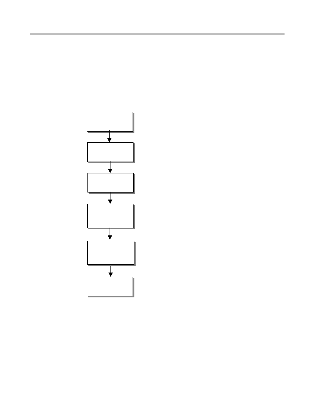
Installation and Configuration Workflow
The MGC configuration includes the following main steps: Hardware
Installation, Software Instal l at io n, Network Ser vi ces defi ni ti on and t he MGC
unit configuration. The hardware installation is described in the MGC
Hardware and Installation Guide. The remaining steps are described in this
guide as illustrated in the following chart.
Hardware
Installation
First Entry MCU
IP Configuration
MGC Manager
Software
Installation
MGC Software
Upgrade
(Optional)
MCU definition
in the MGC
Manager
Network Services
Definition
MGC Hardware Guide,
Chapter 2
MGC Hardware Guide,
Chapter 2
MGC Administrator’s Guide,
Chapter 2
MGC Administrator’s Guide,
Chapter 2
(Only for users upgrading from a
previous version)
MGC Administrator’s Guide,
Chapter 2
MGC Administrator’s Guide,
Chapter 3
1-6
Figure 1-1: Installation and Configuration Workflow
Page 19
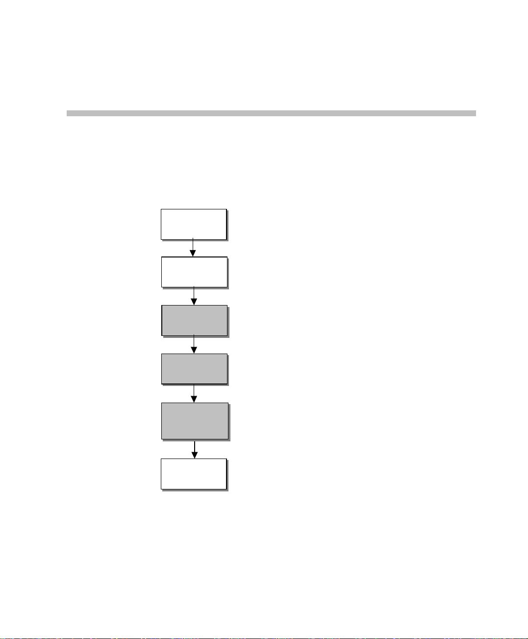
Sof t ware Installation
This chapter describes the MGC Manager software installation and the
definition of the MCU(s) in the MGC Manager application.
2
Hardware
Installation
First Entry MCU
IP Configuration
MGC Manager
Software
Installation
MGC Software
Upgrade
MCU definition
in the MGC
Manager
Network Services
Definition
MGC Hardware Guide,
Chapter 2
MGC Hardware Guide,
Chapter 2
MGC Administrator’s Guide,
Chapter 2
MGC Administrator’s Guide,
Chapter 2
MGC Administrator’s Guide,
Chapter 2
MGC Administrator’s Guide,
Chapter 3
Figure 2-1: Installation and Configuration Workflow - Software Installation
2-1
Page 20
Chapter 2 - Software Installation
Only users (MGC Manager operators) with Superuser rights can perform MGC
Manager configurat ion t asks. In additi on the use r mus t ha ve Sup eruse r right s on
the computer on which the MGC Manager application is running, or any other
permission than enables the application to access the Registry (read/write) and
read/write files on the C: drive (root directory) and under the Windows directory
folder.
MGC Manager Software Installation
To set up conferences and control the MGC unit you need to install the MGC
Manager software on your computer.
Close all programs before insta lli ng the MG C Mana ger so f tw are .
To install the MGC Manager software:
The MGC Manager software installation procedure is identical for new
installations and for upgrade s from previ ous vers ion s.
2-2
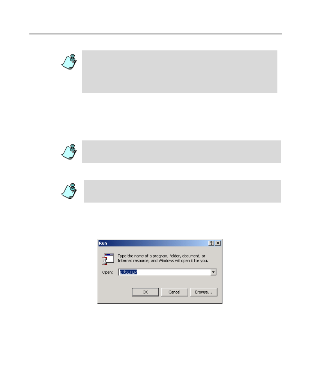
1. Insert the software CD into the CD drive.
2. On the Start menu, click Run.
The Run dialog box opens.
3. Type D:\SETUP (where D is the name of the CD drive) and click OK.
Page 21
MGC Administrator’s Guide
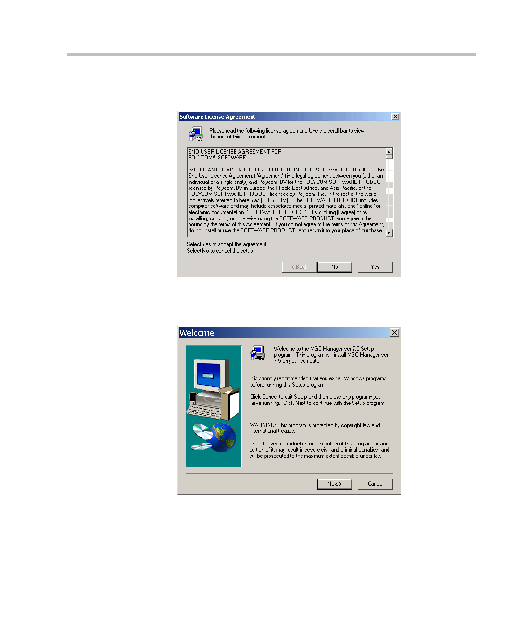
The installation wizard starts a nd the Software License Agreement
window opens.
4. Click Yes to accept the software license terms.
The Welcome screen opens.
5. Read the notices and then click Next.
2-3
Page 22
Chapter 2 - Software Installation
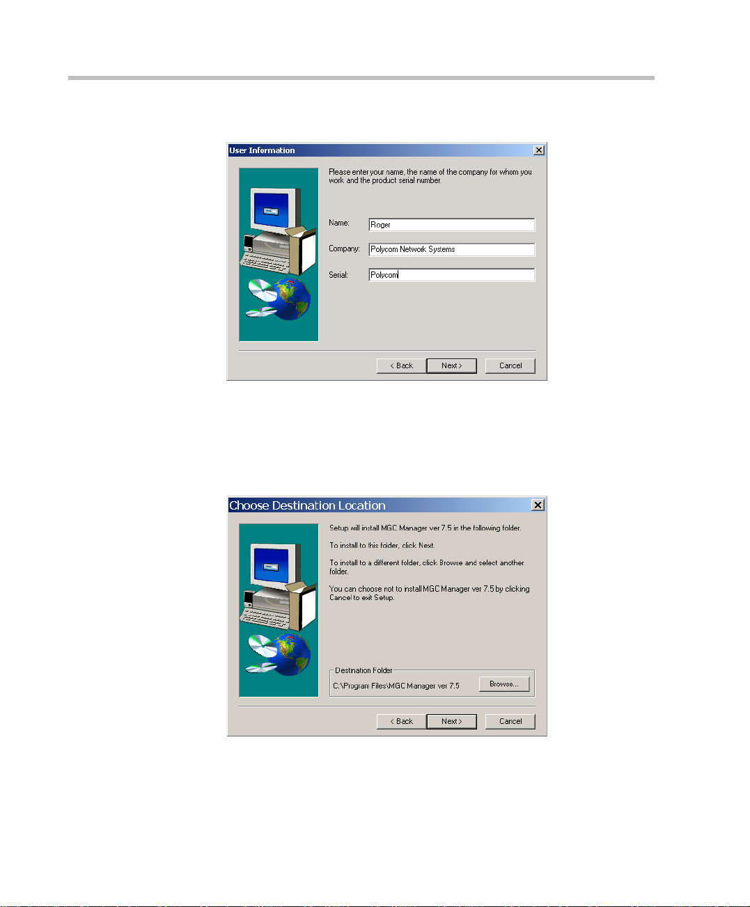
The User Information screen opens.
6. Type your name and the name of your company in the appropriate text
boxes.
For a standard installation, enter Polycom in the Serial box.
Click Next.
2-4
The Choose Destination Location screen opens.
Page 23
MGC Administrator’s Guide
7. Select the directory in which to install the MGC Manager software. To
accept the default directory, click Next.
To change the directory, click Browse, choose the directory in which to
install the software, and then click Next.
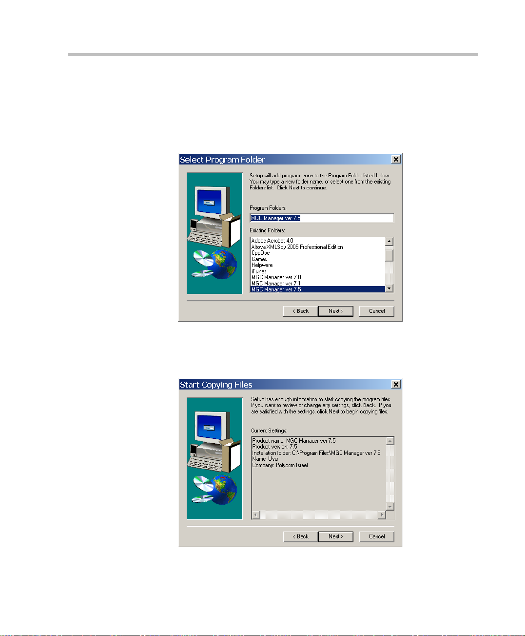
The Select Program Folder screen opens.
8. Select the Program fo lder in which to install the M G C Manager’s icons.
To accept the default folder, click Next.
The Start Copying Files screen opens.
2-5
Page 24
Chapter 2 - Software Installation
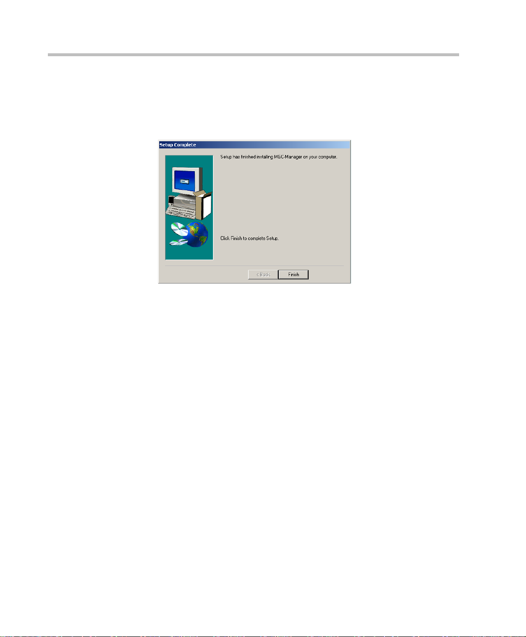
9. To change an installation setting, click Back until the appropriate screen
appears. Click Next to start copying the files to your hard disk.
When the installation procedure has finished, the Setup Complete screen
opens.
10. Click Finish.
The MGC Manager software is now installed on your computer.
2-6
Page 25

First Entry IP Configuration
During the hardware installation process, a network IP address should have
been assigned to the MCU. The IP address must be properly assigned to the
MCU in order for the MGC Manager to connect to it. For more in formation
about First IP Configuration on the MCU, refer the MGC Hardware and
Installation Guide, Chapter 2.
Another method to connect to t he MC U and modi fy its IP conf igurati on i s via
a telephone line with a modem or direc tl y via a ser i al co nnect i on. F or det ai ls,
see "Appendix B: PPP Setup".
MCU Definition
The MGC Manager can connect to several MGC unit simultaneously. The
first time you run the MGC Manager application, or when a new MCU is
added to your configuration, you must define the MCU’s connection
parameters to enable the communication between the MGC Manager and the
MGC unit.
MGC Administrator’s Guide
The MGC unit must be installed and its IP address properly configured before
defining its connection parameters in the MGC Manager application.
To define an MGC unit in the MGC Manager application:
When opening the MGC Manager application, the Reservations in Acc ordD B
window opens automatically. Click on any area of the MGC Manager window to
move the Reservations in Accord DB window to the back.
1. In the MGC Manager Browser pane, right-click the MCUs Network icon,
and then click New MCU.
2-7
Page 26
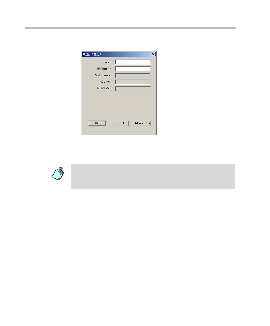
Chapter 2 - Software Installation
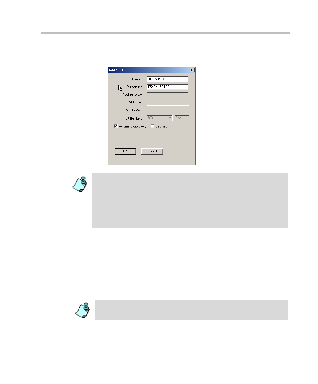
The Add MCU dialog box opens.
2. In the Name box, enter the name of the MCU. Specify a name that clearly
identifies the MCU.
3. In the IP Address box type the IP Address of the MCU.
2-8
The IP address must be ide ntica l to the on e conf igured i n the MC U durin g first IP
Configuration. For more details, see t he MGC-25 Get ting Started Guide,
MGC+50/100 Gettin g Started Guide and MGC-50/100 H ardwa re and Installation
Manual.
4. If you are not using a secured (SSL) connection between the MGC
Manager and the MCU, and if you let t he system aut omatical ly select t he
port for communication and d ata t ransacti ons betwe en them, you can use
the system defaults and end the MCU definition.
Click OK.
5. To override the automatic port selection and manually define the port
number between the MCU and the MGC Manager, click the Advanced
button.
Page 27
MGC Administrator’s Guide
The Port Number field, and the Automatic Discovery and Secured check
boxes, appear in the Add MCU dialog box.
The Port Number field id enti fie s the MCU port to which the MGC Manag er i nit ial ly
connects. If the Automatic Discovery option is enabled, then after initially
connecting to the MCU, the system checks the system configuration file
(system.cfg) for the preferred port settings. The preferred port is defined in the
GENERAL section of the system.cfg file, in the PREFERRED_PORT flag. If the
preferred port differs from the currently connected port, then the system
disconnects and reconnects using the preferred port and replaces the Port
Number with the preferred port.
6. To manually define the Port Number, clear the Automatic Discovery
check box.
7. In the Port Number field, select the listening port number from the drop
down list. The default port number is 5001. The Internet Assigned
Numbers Authority (IANA) has assigned port number 1205 to MCUs In
new installations, it is re com mended to select the IANA port (1205).
If you are upgrading an existing installation and you do not wish to
change the firewall configuration, use the default setting (5001).
To define a secured connection betw een the MGC Ma nager an d the MC U, refer
to “Defining a Secured (SSL) Connection to the MCU” on page 2-10.
8. Click OK.
2-9
Page 28
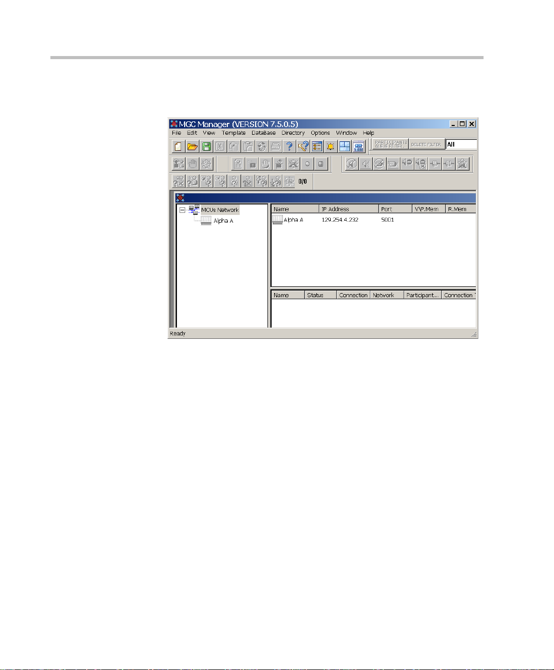
Chapter 2 - Software Installation
The Add MCU dialog box closes. A new icon with the specified MCU
name appears in the Browser pane, below the MCUs Network icon.
9. To connect to an MCU, see the MGC Manager User's Guide, Volume I,
Chapter 3, “Connecting to an MCU”.
Defining a Secured (SSL) Connection to the MCU
SSL (Secure Socket Layer) enables secure HTTP connection on MCUs with
XPEK Operating Systems. An SSL Certificate is required to enable SSL-level
security for the MCU’s connection to external applications. SSL uses a third
party, that is the Certificate Authority, to identify HTTP transactions and
secure them using the HTTPS protocol.
The SSL certificate must be obtained on first connection to the MCU, once
the MCU is defined in the MGC Manager application.
2-10
Page 29
MGC Administrator’s Guide
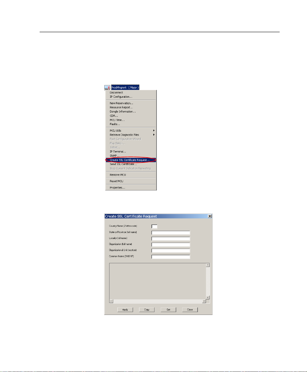
To obtain the SSL certificate:
1. Connect to the MCU.
2. Right-click the unit’s icon or name, and then click C reate SSL
Certificate Request.
The Create SSL Certificate Request dialog box opens, where you can
enter data for the request and apply.
2-11
Page 30
Chapter 2 - Software Installation
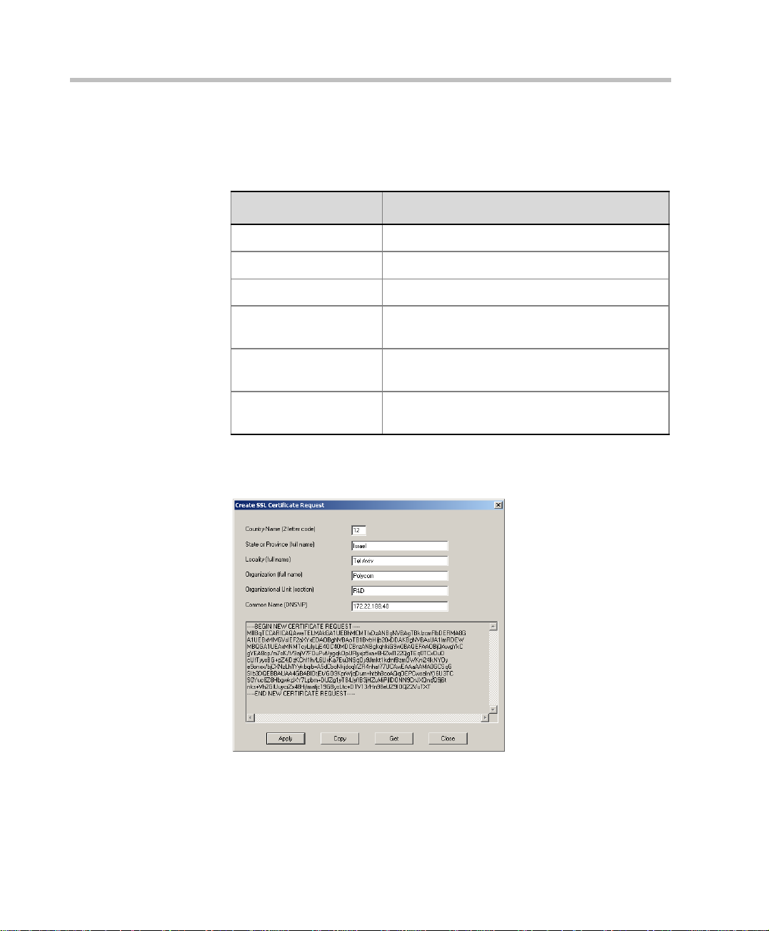
3. Enter information for all the following fields, as they are mandatory for
the request:
Table 2-1: SSL Certificate Request - Required Information
Field Description
Country Enter any 2 letter code for the country name.
State or Province Enter the full name of the state or province.
Locality Enter the full name of the town/city/location.
Organization Enter the full name of your organization for
which the certificate will be issue d.
Organizational Unit Enter the full name of the unit (group or division)
for which the certificate will be issued.
Common Name
(DNS/IP)
Enter the DNS or the IP address of the MCU.
4. Click Apply.
The new certificate request appears in the details box.
5. Click Copy, then click Close.
For a previously defined MCU for which SSL has been obtained before,
click Get to get the latest certificate re quest from the MCU.
2-12
Page 31

MGC Administrator’s Guide
6. In the browser, access your preferred certificate authority (for example,
http://www.thawte.com and select from the quick login box: Certificate
Status), paste the certificate request from MCU and submit.
The authority issues the SSL certificate, and sends the certificate by text
to you by E-mail.
7. When the E-mail with the c ertificate arrives from the authority, select the
text and click Copy.
8. Back in the MGC Manager application, right-click the MCU’s icon and
click Send SSL Certificate.
The Send SSL Certificate dialog box opens.
9. Paste the certificate’s text in the Send SSL Certificate window.
2-13
Page 32

Chapter 2 - Software Installation
10. Click Send.
The MCU validates the certificate.
— If the certificate is not valid, an error message appears.
— If the certificate matches the private key, and the task is completed, a
11. Res et the MCU.
The system has access to the SSL-secured port 443.
If the preferred port or preferred secured port differs from the currently
connected port, then the system disconnects and reconnects using the
preferred port or the preferred secured port, and replaces the Port
Number with the preferred port or preferred secured port.
To enable a Mandatory and Secure connection to the MCU:
1. Before connecting the MCU, right-click the MCU icon and click MCU
Utils, then click Edit “system.cfg”.
The SysConfig dialog box opens.
2. In the GENERAL section, set the following flags:
confirmation message indicating that the certificate was created
successfully is disp la yed.
2-14
— SECURED_PORT_MANDATORY_FOR_API=YES
— SECURED_PORT_MANDATORY_FOR_FILE=YES
— PREFERRED_SECURED_PORT=443
3. Click OK and then reset the MCU.
4. Right-click the MCU icon and then click Properties.
Do not connect to the MCU. When yo u right -cl ick the MC U, the MC U should be
disconnected and the icon appear grey.
The Properties dialog box opens.
Page 33

MGC Administrator’s Guide
5. Click Advanced.
The Port Number field, and the Automatic Discovery and Secured check
boxes, appear in the Properties dialog box.
6. Clear the Automatic Discovery check box.
7. In the Port Number box that is enabled, enter port 443.
8. Select the Secured check box to enable mandatory security.
9. Click OK.
2-15
Page 34

Chapter 2 - Software Installation
10. Connect to the MCU.
When reconnected, the MCU uses the secured port.
After reconnecting, it is highly recommended to change the login password.
Viewing the MCU Connection Type in the MGC Manager Application
When mandatory security is enabled, on first connection after the reset, th e
MCU will automatically use onl y the preferred SS L-secure d port 443, and th e
HTTPS protocol. The HTTPS protocol is indicated in the Connections list
Protocol column under the MCU Configuration icon. Port 443 and the
Secured (the lock) icon are indicated in the MGC Manager window’s status
bar.
2-16
Page 35

MGC Administrator’s Guide
MGC Configuration - Setting the MCU Date and Time
The first time you install t he MCU, if you are movi ng t he MC U to a different
location, or if the MCU is located in a different time zone from the MGC
Manager, you have to set the MCU date and time to synchronize the MGC
Manager.
The time format used in the MGC Manager is taken from the Operating System
installed on the PC running the MGC Manager. This allows 12-hour AM/PM and
24-hour formats to be used.
You can set the MCU time manually, or automatically either by updating it
according to the MGC Manager application or synchronizing it with an
external NTP server. The synchronization with an external NTP server is
available only for MCUs with XPEK operating syst em and it en ables accurate
time calculation that is essential for cascaded or recurring conferences.
To set the MCU date and time:
1. Connect to the MCU.
2. Once connected, right-click the MCU icon, and then click MCU Time.
2-17
Page 36

Chapter 2 - Software Installation
The MCU GM T Time dialog box opens.
The Use NTP Server check box and field is only displayed in XPEK Systems.
You cannot set the MCU’s time or connect to the NTP server, when there are
On Going conferences on the bridge.
2-18
3. The following fields are available:
Table 2-2: MCU GMT Time Options
Field Description
MCU GMT Date From the calendar, first select the month/year and
then click the day of the month.
MCU Local Time Displays the MCU’s current local time settings.
The local time is calculated according to the MCU
GMT Time and the MCU GMT Offset.
MCU GMT Time Displays the MCU’s current GMT time settings.
T o ma nually mo dify the GMT T ime, clic k on the hours
or minutes section of th e time and either use the
scroll arrows to change the value, or enter the new
value.
Page 37

MGC Administrator’s Guide
Table 2-2: MCU GMT Time Options
Field Description
MCU GMT Offset Displays the currently defined time zone differe nce.
To manually modify the GMT Offset, click on the
scroll arrows to change the value, or enter the new
value.
Note: GMT offset can be set in minutes, for example:
5 hours and 45 minutes.
Get Oper
Time&GMT
Get Oper Time Click this button to automatically update the MCU's
Use NTP Server This field is only applicable to XPEK systems.
Operator Local
Time and Date
Operator GMT
Offset
Click this button to automatically update the MCU's
Date, Time and time zone to match the MGC
Manager’s date, time and time zone settings.
Time and Date to match the MGC Mana ger’s time
and date settings (without GMT offset).
Select this check box to sy nchroniz e the time with an
NTP server. Enter the IP address of the required
NTP server.
Displays the local date and time as set in the MGC
Manager (this time is taken from the Windows
operating system).
The time zone dif feren ce as set in the M GC Mana ger
(this time is taken from the Windows operating
system).
To set the time on th e MCU using an NTP Server:
1. In the MCU GMT Offset box, enter the time difference between the MCU
Local Time and MCU GMT Time.
2. Select the Use NTP Server check box, and enter the IP address of the
NTP server.
3. Click OK.
NTP Server synchronization may take up to an hour. All time-related
settings, such as the scheduled Starting Time of Reservations, are
adjusted.
2-19
Page 38

Chapter 2 - Software Installation
To set the time on the MCU automatically, using the MGC Manager time
settings:
1. Click the Get Oper Time&GMT button or Get Oper Time button.
2. Click OK.
To set the time on the MCU Manually:
1. In the MCU GMT Time box, enter the appropriate MCU GMT time by
either clicking on the scroll arrows to change the value, or retyping the
new value.
2. Set the MCU GMT Offset (hours), by clicking the scroll arrows to change
the value, or retyping the new value.
3. Click OK.
Modifying the MCU Local Time for Daylight Savings
To modify the MCU Local Time for daylight savings:
1. In the MCU Time dialog box, change the MCU GMT Offset.
The MCU local time will be changed accordingly. For example, if the
Local MCU Time shows 11:00 and the MCU GMT Offset is set to 2,
changing the MCU GMT Offset to 1 will change the MCU Local Time to
10:00. The MCU GMT Time will remain unchanged.
2. Click OK.
2-20
Page 39

MGC Unit Software Installation
When upgrading the soft ware f r om a pr ev io us v e rs io n, you need to download
the new MCU version to the MCU unit. This process may also be required
when replacing or upgrading the control unit of the MCU.
Before you upgrade the MGC unit software, it is important to backup all
reservations in the MCU . This i s to safeguard against reservatio ns being lost. For
more details, see Chapter 5, “Backing up Reservations” on page 5-102.
To install the MCU software:
1. Select the MCU to which you want to download software.
2. On the File menu, click Download MCU Software.
Alternatively, right-click the MCU icon, clic k MCU Utils, and then click
Download MCU Software.
MGC Administrator’s Guide
2-21
Page 40

Chapter 2 - Software Installation
A message is displayed reminding you th at you must have a vali d dongl e
attached to the MCU.
3. Click OK.
The Logon dialog box opens.
The Login Name and Password of the current logged in operator are
entered by default. If required, enter another login name and password.
4. Click OK to login or Cancel to continue without logging in.
If you have selected Cancel, a message is displayed indicating that
connection will be established without login. Click YES to cont i nue.
The Software Installation dialog box opens, with the selected MCU
displayed in the MCU List box.
2-22
5. Select the Install Default Services check box to download the default
IVR Service and Entry Queue Service. The default IVR Service is in
English and is named IVR75. The default Entry Queue Service is in
English and is named EQ75. You can manually install the default
English IVR Service and Entry Queue Service or the English and
Spanish IVR and Entry Queue Services. For more information , s ee
“Manual Installation of the Default Message Services” on page 2-28.
Page 41

MGC Administrator’s Guide
6. You can download software to all MCUs l iste d in the MCU List in one
operation.
Make sure that all MCUs to update appear in the MCU List.
To add an MCU to the list:
a. Click the Add MCU button.
The Add MCU dialog box opens.
b. In the MCU Name box, type the name of the MCU.
c. In the MC U IP box type the IP address of the MCU.
d. The Login and Password fields are filled with the login name and
password of the logged in operator.
e. Click OK.
The Add MCU dialog box closes and the name of the MCU is
added to the MCU list.
To remove an MCU from the list:
a. In the MCU List, click the MCU to remove.
b. Click the Remove MCU button.
The MCU Name is removed from the MCU List.
7. In the Enter path to source files box, type the full path to the folder
containing the software version. Alternatively, click the Browse button
and use the standard W ind ows techniques t o select the Folder containing
the software.
2-23
Page 42

Chapter 2 - Software Installation
This folder is named Vaaa.bbb, where aaa is the MGC Manager version
number, and bbb is the MCU version number.
You need to select the folder containing the latest version number, and not the
sub-folder labeled Disk 1.
2-24
8. Click OK.
The software version’s path is displayed in the Enter path to source files
box.
Page 43

MGC Administrator’s Guide
9. To install only selected files, do the following:
a. Click the Custom button.
The Custom dialog box opens listing the files that can be installed
on the MCU. All the files are checked (sel ected). Only checked files
are copied to the MCU.
b. To change the selection of all files, click Toggle All.
c. Select the check box of a file to select or clear its selection.
d. When you are finished selecting the files you want to install, click
OK.
The Custom dialog box closes and you are returned to the Software
Installation dialog box.
10. Click the Install button to start the installation procedure.
• After you have successfully installed the latest software version, it may be
necessary to restore th e backed up file s. For mo re inform ation o n backi ng up
and restoring reservations, see Chapter 5, ”Reservations Backup and
Restore” on page 5-102.
• When you upgrade the MCU’s software, the existing card configuration files
are automatically restored.
• If you are upgrading from version 5.x or 6.x, after the completion of the
upgrade process, you must manually update the existing Entry Queue
Services by adding the voice message files prompting for the conference
Numeric ID, otherwise the participants are placed on hold and cannot move
to the target conferences.
• If you have installed the Default Services during the MCU Software
installation and you do not need to manually install additional Message
Services (such as the Spanish IVR Message Service), reset the MCU at the
end of the MCU software installation process.
2-25
Page 44

Chapter 2 - Software Installation
Dongle Information
The MGC-50/100 is shipped with a serial dongle installed on COM1 of the
rear panel. The MGC-25 is shipped with a serial dongle installed on parallel
port of the rear panel.
To verify if you have a dongle your are required to inspect the rear panel of
the MCU as shown in Figure 3.
2-26
Figure 3: MCU-100 & MCU-25 rear panels and their dongles
Page 45

MGC Administrator’s Guide
removed or dam aged.
be void if seal label is
Product warr a nty will
WARNI N G
POLYCOM
LAN
VGA
MOUSE
KEYBOARD
COM2
ALARMS
COM1
R
Figure 4: MCU+ 50 rear panel and dongle location
The dongle on the MGC+ 100 is located in the identical location. On both
the MGC+ 50/100, an additional bracket is installed together with the
dongle. For more i nformation on the inst allation and rem oval of the don gle
on the MGC+ 50/100, refer to the MGC+ Hardware and Installation
Manual.
The Dongle was introduced on the MCU and MGC Manag er in versi on 5.02.
Each dongle installed on the MCU is backward compatible with current or
previous MGC Manager versions.
Only customers with an active Polycom Premier Family Maintenance
Agreement are entitled to upgrade a version for free.
When upgrading the MGC Manag er version, you are r equired to upgr ade your
Dongle. For details of the dongle upgrade procedure, refer to the Release
Notes of the relevant version.
2-27
Page 46

Chapter 2 - Software Installation
Manual Installation of the Default Message Services
The MGC software kit is shipped with the voice messages required for the
default Entry Queue Service and the default IVR Message Service. These
messages can be autom atically installed on the MCU during the software
installation. You can also manually install the default Message Servi ces at the
end of the installation process.
The MGC software and documentati on CD contains two IVR Service folders:
• English
• English and Spanish
The Automatic installatio n of Messa ge services d uring MCU soft ware upda te
automatically installs the English only Message services. The manual
installation process enables you to install the English and Spanish Message
Services as well as the English only. When you install the English and
Spanish IVR Services, two separate IVR Services are created on the MCU
and the English IVR Service is automatically set as the default IVR Service.
To restore the Default IVR Service:
The default Message Services are installed using the Restore Configuration
utility.
2-28
Restoring the IVR Services overwrites existing IVR Services.
1. Right-click the MCU icon, click MCU Utils, and then click Restore
Configuration.
The Restore Configuration dialog box opens.
2. Enter the path to the folder containing the configuration files to be
installed, or click the Browse button to locate them.
Page 47

MGC Administrator’s Guide
If you have selected Browse, the Browse for Folder dialog box opens,
enabling you to select the source folder.
3. From the version 7.5x software folder, select English V75 IVR or
English and Spanish V75 IVR folder, according to the required
Message Service, and click OK.
The system returns to the Restore dialog box.
4. Click OK to continue.
The Restore dialog box is displayed.
The system lists the configuration folder (CFG box) and the audio files
(Msg box) used in the IVR Service.
5. Click the Select All button.
6. Click OK to install the default Message Servic es on the MCU.
7. At the end of the Restore process, a message is displayed indicating that
the MCU must be reset to be able to use the new Message Services.
8. Click OK and reset the MCU.
2-29
Page 48

Chapter 2 - Software Installation
After the completion of the upgrade process, you must manually update the
Existing Entry Queue Services by adding the voice message files prompting for
the conference Numeric ID, otherwise the pa rticipants are placed on hold and
cannot move to the target conferences.
2-30
Page 49

Command Line Launch
The MGC Manager can be launched by other applications using the
Command Line Instruction.
When accessing the MGC Manager from an external application, the
application must read the “.exe” file name stored in the Windows registry.
After reading the file and version name, the IP address, MCU name, user
login name and password are added.
Windows Registry Access
The Windows Registry uses the following format:
HKEY_LOCAL_MACHINE \ SOFTWARE \ POLYCOM \
MGC_MANAGER \ Versions\VerX.Y
MGC Manager launch format requires the full path and name of the specific
MGC Manager version, including IP, MCU name, User login and password.
For example:
c:\ProgramFiles\MGCMa nager\ O perWS .exe ip=172.22.168.135
MCUname= Alpha12 login=POLYCOM psw=POLYCOM
MGC Administrator’s Guide
Spaces (character) are forbidden between the argument name, the '='
character and the version value.
Activate the application and connect. When the MGC Manager window
opens, a single MCU is displayed.
The MGC Manager can be activated using the Windows Start menu as
illustrated in the Run window:
2-31
Page 50

Chapter 2 - Software Installation
2-32
Page 51

Defining Network Services
3
Hardware
Installation
First Entry MCU
IP Configuration
MGC Manager
Software
Installation
MGC Software
Upgrade
MCU definition
in the MGC
Manager
Network Services
Definition
Providers of communic ation services such a s telephone carriers use dif ferent
communication protocols, lines, equipment and configurations. This can be
true even in different regions of the same country.
The MGC unit is designed to work with different service providers/
communication lines. In particular, the MGC unit can be connected to any
public or private network that supplies ISDN lines, ISDN leased lines,
T1–CAS lines, ATM connections or IP connections. These include long
distance carrier services and local area services. In addition, the MGC unit
may be connected to a serial network usin g the MPI ser ial networ k inter face
card.
To enable the MCU to connect participants using any of the following
networks: ISDN, PSTN, T1-CAS, ISDN-NFAS, ISDN-Leased Lines, IP,
serial connection (MPI) and ATM, the network parameters must be defined
in the Network Services. You must also set up the network parameters
whenever you:
• Connect the MGC unit to a switch in a new site
• Add a new switch to an existing site
• Add ISDN/T1–CAS lines to the system
• Connect the MGC to an additional LAN zone
• Change the network properties
Only MGC Manager operators with Superuser rights can perform MGC
Manager configuration tasks. In addition, the user must have Superuser rights
on the computer on which the MGC Manager application is running, or any
other permission than enables the application to access the Registry (read/
write) and read/write files on the C: drive (root directory), under the Windows
directory folder.
3-1
Page 52

Chapter 3 - Defining Network Services
ISDN Network Service
The Net-2/4/8 Network card installed in the MCU interfaces between the
MGC unit and the ISDN switch. The Network Service is used to define the
properties of the switch and the ISDN lines running from the switch to the
ISDN Network card. Each group of ISDN lines having the same
characteristics and originating from the same ISDN switch, will be assigned
to the same Network Service. The ISDN Network Service is also used for
connections via PSTN, leased lines and NFAS configuration of ISDN lines.
T1–CAS Network Service
The Net-2/4/8 Network card installed in the MCU interfaces between the
MGC unit and T1–CAS lines. The T1–CAS Network Service is used to
define the properties of the switch and the T1–CAS lines running from the
switch to the Net-2/4/8 Network card.
IP (H.323 and SIP) Network Service
The IP Network Service defines the properties of the IP network and the IP
cards (installed in the MCU) used for connecting IP (H.323 and SIP)
endpoints to the conference. Several of the network components are used by
both H.323 and SIP endpoints to connect to the conference, and the same IP
card is used for H.323 and SIP connections.
3-2
ATM Network Service
The ATM Network card installed in the MCU interfaces between the MGC
unit and the ATM Network (FVC), usually via a UNI address router (V-Gate).
The Network Service is used to define the properties of the ATM switch and
the V-Ga te to which the MGC unit is c onnected.
MPI Serial Network Service
The MGC unit may be connected to endpoints over a serial connection using
the V.35, RS-449 and RS-530 serial standards. The MPI-8 Network Interface
module together with the MPI box interfaces between the serial equipment
and the MGC unit. The MPI Network Service is used to define the properties
of the serial connections between the MGC unit and the data communication
equipment.
Page 53

Defining an ISDN Network Service
The MCU may be connected to ISDN lines provided by different carriers.
Each carrier has unique characteristics, and may have different pricing
programs. T o use th ese lines, together with the carrier’s special prog rams, you
need to first obtain the relevant information from the carrier and then define
their parameters in the MGC Manager applica tion.
To define a New ISDN Network Service connection:
1. Connect the MGC Manager to the MCU. For m ore information, see the
MGC Manager User's Guide, Volume I, Chapter 3, “Connecting to an
MCU”.
2. In the Browser pane, expand the MCU tree.
3. Expand the MCU Configuration tree.
4. Expand the Network Services tree.
The list of Network Services is displayed.
MGC Administrator’s Guide
5. Right-click the Network Services - ISDN icon, and then click New
Network Service.
3-3
Page 54

Chapter 3 - Defining Network Services
The New Network Services configuration wizard opens. The wizard
displays a series of dialog boxes.
— To display the next dialog box, click on Next.
— To display the previous dialog box, click Back.
Settings Dialog Box
The first dialog box displayed by the wizard is used to identify the
network service to the system.
3-4
6. Define the Settings parameters as follows:
Table 3-1: Settings Dialog Box Options
Field Description
Net Service Name Specify the service provider’s (carrier) name or any
other name you choose, using up to 20 characters.
The Network Servi ce Na me id enti fie s the service to
the system.
Page 55

MGC Administrator’s Guide
Table 3-1: Settings Dialog Box Options
Field Description
Span Type Spans are ISDN lines supplied by the service
provider to the MCU. You can define each span as a
separate Network Service, or you can define all the
spans from the same carrier under the same
Network Service.
Select the span typ e from the drop-down list; select
either T1 (usually in the U.S., h as 23 B c hannels + 1
D channel), or E1 (usually in Europe, has 30 B
channels + 1 D channel).
The MCU may contain several network cards. A
Net-E1/Net-T1 card may be connected to two
spans; both spans must be of the same span type.
A Net-2/4/8 card may be connected to 2, 4 or 8
spans respectively with both spans types connected
to it.
Service Type Select the service typ e from th e drop-d own list . The
following options are available:
• PRI (Primary Rate Interface) - default selection
for all ISDN lines that are not leased lines
• Leased-24 - leased line applicable to T1 lines
• Leased-30 or Leased -31 - leased line ap plicable
to E1 lines.
For a detailed description of the ISDN Leased lines
Network Service definition, see “Defining ISDN
Leased Lines” on page 3-19.
NFAS (Non-Facility
Associated
Signaling)
Select the NFAS check box to define a network
service using ISDN-NFAS lines. For more
information on this option, see “Defining ISDN
Non-Facility Associated Signaling (NFAS)” on
page 3-24.
7. Click Next.
The PRI Settings dialog box opens.
3-5
Page 56

Chapter 3 - Defining Network Services
PRI Settings Dialog Box
The the PRI Settings dialog box enables you to define the properties of
the PRI Service Type.
3-6
If you do not need to define a sub-service, you can use the defaults, and just
click
Next to display the subsequent dialog box.
8. Define the PRI Settings properties as follows:
Table 3-2: PRI Settings Dialog Box Options
Field Description
Default num-type The num-type defines ho w the sy ste m ha ndl es the
dialing digits. For exam ple , if you type ei ght di ali ng
digits, the num-type defines whether this number is
national or international. If the PRI lines are
connected to the MCU via a network switch, the
selection of the Num Type is used to route the call
to a specific PRI line.
If you want the network to interp ret the dialing di gits
for routing the call, select Unknown.
Page 57

MGC Administrator’s Guide
Table 3-2: PRI Settings Dialog Box Options
Field Description
Num-plan Set the type of signaling (Number Plan) that the
MGC unit will use for this service—for example,
ISDN or telex. Enter the number plan according to
information given by the service prov id er.
For video conferencing purposes, select the ISDN.
Voice Indicate the frequency of the data being sent.
For practical purposes, the Voice option is set to
3.1 KHz as it is the more widely used frequency.
However, it is important to make sure that the
system receiving the voice data is set to the same
frequency as that of the data being sent.
Sub Services Some service providers (carriers) may have
several service programs that can be used. They
may also use a backup service provider in case of
malfunction in the ISDN network. You may define
several service programs as sub-services and set
one of them as the default.
If the PRI lines are connected to the MCU via a
network switch, the sub-service may be used to
route the calls to a certain service provider.
The Sub-Service list displays the list of currently
defined sub services . To select the service pro gram
to be used for the PRI line channels, click the Add
button. The Sub-Service dialog box opens.
T o remove a service program f rom the li st, highl ight
it in the list box and click the Del button. The
selected sub-service is removed from the list.
To set a service program as the default, highlight it
in the list box and click the Default button. The
selected sub-service becomes the default service
program for the current service provider. The word
“default” appears in parentheses next to the subservice’s name.
To edit the parameters of a sub-service, doubleclick its name in the sub-services list. The Sub-
Service dialog box opens.
3-7
Page 58

Chapter 3 - Defining Network Services
9. If you are not defining a sub-service or if you have completed the subservice definition, c lick Next to continue.
The Span Definition dialog box opens.
Defining Sub-Services
10. This step is required only if your ISDN network includes a sub-service,
otherwise, skip these steps.
In the PRI Settings dialog box, in the Sub Services section, click the Add
button to add the sub-servi ce, or double-clicked the Su b Ser v ice name t o
edit its param eters. The Sub Service dialog box opens.
3-8
a. Fill in the Sub Service dialog box as follows:
Table 3-3: Sub Service Dialog Box Options
Field Description
Name Type the name of the sub-service using up to 20
characters. This name identifies the sub-service.
Dial-out Prefix Type the prefix that your PBX needs to dial out in
order to use this service program. Leave this field
blank if a dial-out prefix is not required.
Page 59

Table 3-3: Sub Service Dialog Box Options
Field Description
MGC Administrator’s Guide
Information
Element
Net Specific Select the desired service program from the drop-
Backup Dial-Out For future release.
For future release.
down list . The servic e programs are listed
according to the service providers.
If no special specification is required, select the
NULL option.
b. Click OK.
The Sub Service dialog box closes and you are returned to the PRI
Settings dialog box.
c. Click Next.
The Span Definition dialog box opens.
3-9
Page 60

Chapter 3 - Defining Network Services
Span Definition Dialog Box
The Span Definition dialog box is used to define the PRI span technical
properties. The default values displayed for the Span’s technical
parameters are appropriate for most ISDN networks, therefore, you can
skip their definition by clicking Next to mov e to the subsequ ent wind ow.
If you do not know the technical prop erties of y our span , try th ese values
first.
3-10
The Leased L ine s s ection of this di alog box is disa bl ed, unle ss you have sp ecif ied
Leased Lines as the Service Type in the Settings tab. For more details about
Leased Lines definition, see “Defining ISDN Leased Lines” on page 3-19.
11. Define the Span Definition properties as foll ows:
Table 3-4: Span Definition Dialog Box Options
Field Description
Framing Framing refers to the frame format used by the
carrier for the network interface.
Select th e appropriate option from the drop-down
list.
Page 61

MGC Administrator’s Guide
Table 3-4: Span Definition Dialog Box Options
Field Description
Framing (cont.) If a span type of T1 is specified in the Settings
dialog box, the following Framing values are
available:
• ESF (Extended Super Frame format of 24
frames, which provides enh anc ed
performance). This is the system default
• ESF ZBTSI
• SF SLC96
• SF
If a span type of E1 is specified in the Settings
dialog box, the following framing values are
available:
• CRC4 Si = FEBE (default)
• CRC4 Si = 1
• BASIC, noCRC4
Line Length Indicates the distance between the MCU and the
PBX.
Select the desired option from the drop-down list.
If T1 is specified as the span type in the Settings
dialog box, the following Line Length values are
available:
• 0-133 ft. (0.0 dB)
• 133-266 ft. (-7.5 dB)
• 266-399 ft. (-15.0 dB)
• 399-533 ft. (-22.5 dB)
• 533-655 ft. (-30.0 dB)
If E1 is specified as the span type in the Settings
dialog box, the Line Length value is 0 by default.
3-11
Page 62

Chapter 3 - Defining Network Services
Table 3-4: Span Definition Dialog Box Options
Field Description
Framing (cont.) If a span type of T1 is specified in the Settings
Line Length Indicates the distance between the MCU and the
dialog box, the following Framing values are
available:
• ESF (Extended Super Frame format of 24
frames, which provides enhanced
performance). This is the system default
• ESF ZBTSI
• SF SLC96
• SF
If a span type of E1 is specified in the Settings
dialog box, the following framing values are
available:
• CRC4 Si = FEBE (default)
• CRC4 Si = 1
• BASIC, noCRC4
PBX.
Select the desired option from the drop-down list.
If T1 is specified as the span type in the Settings
dialog box, the following Line Length values are
available:
• 0-133 ft. (0.0 dB)
• 133-266 ft. (-7.5 dB)
• 266-399 ft. (-15.0 dB)
• 399-533 ft. (-22.5 dB)
• 533-655 ft. (-30.0 dB)
If E1 is specified as the span type in the Settings
dialog box, the Line Length value is 0 by default.
3-12
Page 63

MGC Administrator’s Guide
Table 3-4: Span Definition Dialog Box Options
Field Description
Side Select the desired option from the drop-down list.
The following options are available:
• User side (default)
• Network side
• Symmetric side
Note:
If the PBX is configured on the network side, then
the MGC unit must be configured as the user side,
and vice versa, or both must be configured
symmetrically.
Line Codin g Indicates how the bits are sent on a PRI line.
Select the desired option from the drop-down list.
If T1 is specified as the span type in the Settings
dialog box, the following Line Coding values are
available:
• B8ZS (default) - Bipolar 8-Zero Substitution
• B7ZS
• AMI - Alternate Mark Inversion with zero code
suppression
The difference between these modes is the way
eight consecutive zeros enabling information
synchronization are encoded.
If E1 is specified as the span type in the Settings
dialog box, the following Line Coding values are
available:
• HDB3 (default) - Fours z ero s a re rep lac ed by a
code
• AMI - Alternate Mark Inversion with zero code
suppression
3-13
Page 64

Chapter 3 - Defining Network Services
Table 3-4: Span Definition Dialog Box Options
Field Description
Switch Type Select the desired brand and revision level of
RCV Threshold RCV Threshold refers to the minimum detectable
equipment installed in the telephone company’s
central office.
If T1 is specified as the span type, the following
Switch Type values are av ailable:
• AT&T 4ESS
• AT&T 5ESS
• Northern Telecom DMS-100
• Northern Telecom DMS-250
• Ericsson MD110 U.S.
• Siemens U.S.
If E1 is specified as the span type, the following
Switch Type values are available:
• Ericsson MD110 International
• Euro ISDN
signal in a T1 or E1 span on the Net-2/4/8 card
FALC component. This option is used to increase
the signal on E1 or T1 spans when the system
detects a very low signal.
Select the desired threshold values from the list.
The following values are available:
• THRESHOLD 0 (by default)
• THRESHOLD 1
• THRESHOLD 2
• THRESHOLD 3
Note: When you modify the threshold values a
warning is displayed, advising you t o obtain
authorization from system support.
Click OK to confirm the modification.
3-14
Leased Lines The Leased Lines list is enabled when you select
Leased as the Service Type in the Settings dialog
box. For more information on how to configure the
leased line connection, see “Defining ISDN Leased
Lines” on page3-19.
Page 65

12. Click Next to continue.
The Spans and Phones dialog box opens.
Spans and Phones Dialog Box
This dialog box is used to assign circuit id entificat ion numbers and the di al-in
phone number ranges to be used in dial-in conferences. Circuit orders are
automatically assigned to spans. The dial-in phone numbers are allocated to
the MCU by your service provider (carrier) and should be obtained from the
service provider. You specify the range of dial-in numbers in the Spans and
Phones dialog box by en tering the first and last number s in the ran ge. You can
define several ranges for the same span.
MGC Administrator’s Guide
T o define
a span
The number used
to identify the
MCU
To remove a
span
To define a dial-in phone
numbers range
To delete a
currently
defined dial-in
numbers range
T o allocate dialin numbers for
Gateway calls
To delete
allocated dial-in
numbers for
Gateway calls
List of dial-in
phone numbers
and their
ranges
allocated to the
Gateway
3-15
Page 66

Chapter 3 - Defining Network Services
13. Define the Spans and Phones parameters as follows:
Table 3-5: Spans and Phone Dialog Box Options
Field Description
Span Displays the existing definitions of circuit
Dial In Phone Num Lists the phone numbers that will be used for dialing
MCU Number Type a number that will identify the MC U when call ing
identification numbers and circuit orders. If only one
service provider is used , define all the PRI lines here.
For each span that is connected to the MCU and is
included in this Network Service, click the Plus
button to define the new sp ans. Th e Add Span dialog
box opens. For more details see Table 3-6 on
page 3-16.
in, as allocated to the MCU by the service provider.
To define additional dial-in number ranges see
“Defining Dial-In Numbers” on page 3-17.
the participants in dial-out conferences. This number
should be obtained from your system administrator.
The MCU Number is also used in conferences when
the Meet Me Per MCU option is selected as the
connection type for participants.
3-16
Gateway Range Displays the dial-in numbers allocated to Gateway
calls. Click the Plus button to allocate dial-in
ranges to the gateway. The Gateway Phone
Numbers dialog box opens. For more details see
“Defining the Gateway Range” on page 3-18.
If you have selected the NFAS option in the Settings dialog box, an
additional field is displayed in the Spans list. See “Defining ISDN
Non-Facility Associated Signaling (NFAS)” on page 3-24.
Defining Spans
14. To assign circuit identification numbers and orders:
a. In the Spans pane of the Span and Phone dialog box, click the Plus
button.
Page 67

The Add Span dialog box opens.
b. Define the Circuit ID parameters:
Table 3-6: Add Span Dialog Box Options
Field Description
MGC Administrator’s Guide
Circuit ID The Circuit Identification is a logical number used to
identify the span to the MGC Manager. This number
is later used to assign the span to the network card.
Enter any positive intege r from 0 to 65535, t o be used
as the circuit identification number in the MGC
Manager.
Note:
If other services are already defined, make sure to
use numbers other than those already assigned to
the existing services.
Circuit Order The Circuit Order determines the order in which the
MCU uses the spans to dial out. The Circuit Order is
assigned automatically by the system according to
the order in which the spans are added.
In dial-out connections, when the operator calls the
participant, the MGC unit allocates ports from the
spans starting with the span having the lowest
number and the lowest port number within that span.
c. Click OK.
3-17
Page 68

Chapter 3 - Defining Network Services
The Add Span dialog box closes and you are returned to the Spans
and Phones dialog box.
To delete a circuit identificati on entry :
• In the Spans pane, click the Circuit Identification entry you want to
delete and then click the Minus button.
The entry is deleted.
Defining Dial-In Numbers
15. You specify the range of dial-in numbers by entering the first and last
numbers in the range. You can define several ranges for the same span.
To define the dial-in numbers range:
a. In the Spans and Phones dialog box, in the Dial In Phone Numbers
section, click the Plus button.
The Add Phone Num dialog box opens.
3-18
b. In the First Phone Number box, enter the first number in the range
of dial-in numbers.
c. In the Last Phone Number box, enter the last number in the range of
dial-in numbers.
d. Click OK.
Page 69

MGC Administrator’s Guide
The dialog box closes. You are returned to the Spans and Phones
dialog box. The number range appears in the Dial-In Phone
Numbers list.
e. Repeat steps a-d for each number range you need to enter.
To delete a dial-in number entry:
• In the Dial In Phone Number section, click the entry to delete and then
click the Minus button.
• Click Yes when prompted to confirm the deletion.
The entry is deleted.
Sorting the dial-in number list:
Y o u can change the order in whi ch dial-in phon e number ent ries are display ed
by doing the following:
• Click the First Number heading to sort the list in ascending order
according to the First Number value of the entries.
• Click the Last Number heading to sort the list in ascending order
according to the Last Number value of the entries.
Defining the Gateway Range
16. The dial-in numbers to be used for Gateway connections are all ocat ed to
the MCU by your service providers. The range of dial-in numbers
allocated to Gateway calls must differ from the dial-in number ranges
allocated to multipoint conferencing. To define the Gateway dial-in
numbers range:
a. In the Spans and Phones dialog box, in the Gateway Range section,
click the Plus button.
The Gateway Phone Numbers dialog box opens.
3-19
Page 70

Chapter 3 - Defining Network Services
b. In the First Phone Number box, enter the first number in the range
of gateway dial-in numbers.
c. In the Last Phone Number box, enter the last number in the range of
gateway dial-in numbers.
d. Click OK.
The dialog box closes. You are returned to the Spans and Phones
dialog box. The number range appears in the Gateway Range list.
Completing the ISDN Network Service Definition
Once you have finished filling in all the Wizards screens, click the Finish
button in the Spans and Phones dialog bo x .
The data you have specified will b e vali dated, after which the ISDN Network
Service will be added to the list of ISDN network services of the MCU.
Defining ISDN Leased Lines
With Le ased lines t wo or more por ts are dedi cated to one endpoin t, dependi ng
on the required Line Rate. Each port provides a line rate of 64 Kbps. When
using Line Rates of 128 Kbps, two port s will be assigned to t he endpoint with
leased lines. The endpoint connects directly to the conference, once the
connection is initia ted.
1. Expanded the MCU Configuration tree.
3-20
1. Expanded the Network Services tree.
2. Right-click the Network Services – ISDN icon, and then click New
Network Service.
Page 71

MGC Administrator’s Guide
The Network Service wizard displays the Settings dialog box.
3. Define the Net Service Name and Span Type as you would for a standard
line. For details, see “Settings Dialog Box” on page 3-4.
4. In the Service Type list, select Leased-24 for T1 , or
Leased-30/ Leased-31 for E1.
5. Click Next to continue.
3-21
Page 72

Chapter 3 - Defining Network Services
The Span Definition dialog box opens.
6. Define the applicable span technical properties in the left pane of the
dialog box. For details, see “Span Definition Dialog Box” on page 3-10.
3-22
The Leased Lines pane of the Span Definition dialog box is used to
configure leased lines. The Leased Lines pane is active only if you have
selected one of the leased lines options in the Service Type field in the
Settings dialog box.
To add lines:
a. In the Span Definition dialog box, Leased Line pane, click the New
button.
The Leased Lines dialog box opens:
Page 73

MGC Administrator’s Guide
Leased lines are communication lines that are dedicated to specific
participants. In the Leased Lines dialog box, you select the
participants that will be as signed to this line. The number of ports
allocated to each participant determines the line rat e to be used in
multiples of 64 Kbps, and it depends on the endpoint capabilities.
For example, if the participant's capabilities a llow a line rate of 384
Kbps (6B), the participant will be assigned six (ports).
b. In the Partici pa nt Name box, enter the participant name.
c. In the First Port box, enter the sequential number of the first port
(channel) in the range of channels to be assigned to this participant.
d. In the Last Port box, enter the sequential number of the last port
(channel) in the range of ports (channels) to be assigned to this
participant.
For example, if the line rate to be assigned to t his participant is
384Kbps, assign 6 ports. If this is the first participant you are
defining, you may define the range by indicating the first port as
number 1 and the last port as number 6. However, if this participant
is not the first participant to be defined, the first port number will
have to be the next available sequential number. For example, if the
last port defined for a participant is 16, the first port number to be
assigned to this participant is 17.
e. Click OK.
The participant’s name is added to the Leased Lines list.
f. Repeat steps a to f to define additional participants using this leased
line.
To modify a participant’s configuration:
•In the Leased Lines list, double-click the part ici pan t name.
The Leased Lines dialog box opens.
• Define the participant's param e ters as described in steps 7.b to 7.f.
To dele te a participant’s configuration:
•In the Leased Lines list, highlight the participant name, and then
click the Delete button.
The participant is rem oved from the Leased Lines list.
7. Select the Restricted check box if the endpoints support a li ne r at e o f 56
Kbps per channel, instead of 64 Kbps.
3-23
Page 74

Chapter 3 - Defining Network Services
8. Click Next to continue.
The Spans and Phones dialog box opens.
When defining leased lines, the Dial In Phone Num pane is disabled, as
there is no need to define dial-in phone numbers. The participants are
connected directly.
You can connect more than one PRI leased line per Network Service.
The span definition is identical to the standard T1 definition. For details,
see “Spans and Phones Dialog Box” on page 3-14.
The leased line is always open to the MCU and no dialing is required.
For this reason the MCU Number field is disabled.
For definition of the Gateway Range see the “Spans and Phones Dialog
Box” on page 3-14.
9. Click Finish to complete the Networ k Service definition.
3-24
Page 75

MGC Administrator’s Guide
Defining ISDN Non-Facility Associated Signaling (NFAS)
Non-Facility Associated Signaling (NFAS) only applies to T1 lines and can
be configured in two different ways, depending on the ISDN network cards
installed in your MCU.
Each T1 span has 23 B channels for tra nsferring audio, vide o, or dat a and one
D channel. The D channel acts as a signaling channel, and controls the call
activity.
In systems using NFAS, when you have a Net-2/4/8 card installed in your
system, only one D channel is used. The other spans share the D channel, and
this enables each additional PRI line to use the D channel as a B channel for
audio, video, or data.
The span containing the D channel is called t he Master. The remaining sp ans,
which share this D channel are called Slaves, and the number of B channels
on each Slave line is increased to 24.
The Net-8 card has certain limitations in that you cannot aggregate PRI lines
from another Net-8 card. This means that the maximum number of Slave
spans that can share a Master span is seven, allowing for eight spans in total.
If you are using a Net-T1 card, several PRI lines on different cards may be
aggregated to create one span. In such a case, one D channel controls the call
activity for all the aggregated PRI lines - the Master. The remaining D
channels are used to transfer call data (video and audio data), hence
increasing the number of B channels (from 23 to 24 channels for each Slave
PRI line) that can be used for video conferencing. You can, however,
aggregate Slave spans from different Net-T1 cards to share with one Master.
Theoretically, you can have up to 10 Net-T1 cards having 19 Slaves sharing
with a Master (20 spans in tota l). H owever, it is not practical to have s o many
Net-T1 cards connected to an MCU at any given time.
3-25
Page 76

Chapter 3 - Defining Network Services
To define an NFAS Network Service:
1. In the Settings dialog box select the NFAS check box.
2. Define the remaining settings parameters as described for standard PRI
lines. For details, see “Settings Dialog Box” on page 3-4.
3-26
3. Select Next.
The PRI Settings dialog box opens.
Define the service provider’s parameters as for standard PRI lines. For
details, see “PRI Settings Dialog Box” on page 3-6.
4. Select Next.
The Span Definition dialog box opens.
Define the technical span parameters as for standard PRI lines. For
details, see “Span Definition Dialog Box” on page 3-10.
5. Select Next.
Page 77

MGC Administrator’s Guide
The Spans and Phones dialog bo x opens, displaying the NFAS ID field in
the Spans pane.
6. In the Spans pane, click the Plus button.
The Add Span dialog box opens.
3-27
Page 78

Chapter 3 - Defining Network Services
7. Enter Circuit ID numbers for each span, as per PRI lines.
The Circuit Order is ass ig ned aut om ati cal ly by the s yste m a cc ordi ng to th e ord er
in which the spans are added.
Y o u can c hange the sp an ord er (if the re are se ver al sp ans d efined in the s ystem)
using the Set Before or Set After buttons. These buttons are enabled when the
NFAS option was enabled in the Settings dialog box and you define several PRI
spans to be used as part of the NFAS service.
To do so:
• Click the name of a circuit in the Circuits Order list, which is to be adjacent to
the circuit you are defining.
The circuit’s entry is highlighted.
• To insert the new circuit, do one of the following:
• Click Set Before to insert the new circuit before the highlighted entry.
• Click Set After to insert the new circuit after the highlighted entry.
8. In the NFAS ID bo x, en te r th e NFAS ID number for the span that you are
defining.
9. Select the Master or Slave option, which is applicable to the span that
you are defining.
3-28
— Master - T he D-channel of the first PRI line that will be used to
control the data flow for all the PRI lines bundled as NFAS.
— Slave - The PRI line that is used for data transfer (audio and video
information), increasing th e line rate that can be used to ru n
conferences.
• There are certain li mitati ons when using a Net-8 card. The firs t number should
be that of the Master, and is always 0. The order in which you define the
remaining PRI lines (the Slaves) determines the order in wh ich the lines will be
used for running conferen ces. The NFAS ID number of the first Slave is 1. The
ID numbers for each successive PRI line that is added as a Slave is
sequentially increased by 1.
• If you are using a Net-T1 card, the NFAS ID number that you allocate to the
Master and Slave PRI lines is not important. It is however recommended that
you enter 0 for the Master and increase this number by one sequentially, for
every additional Slave that you define.
• The ID numbers assigned to each span must be identical to the ID numbers
configured on the switch in order for the system to recognize the data flow on
each channel.
Page 79

MGC Administrator’s Guide
10. Click OK.
The Add Span dialog box closes and you are returned to the Spans and
Phones dialog box.
11. To define additional NFAS spans, repeat steps 3 to 7.
12. Define the dial-in phone ranges as described in “Defining Dial-In
Numbers” on page 3-17.
13. Click Finish to complete the Network Service definition.
3-29
Page 80

Chapter 3 - Defining Network Services
Assigning the ISDN Network Service to the NET-T1/NET-E1 Card
To connect the MCU to the ISDN network, you need to configure the
Network Interface Module in conjunction with the ISDN Network Services
defined in the MGC Manager.
The label on the Network functional module indicates the card type.
To assign the ISDN Network Service to the Network Interface module
(Net-T1/Net-E1 Card):
1. Expand the MCU tree.
2. Expand the MCU Configuration tree.
3. Expand the Cards tree.
The Cards list is display ed below the Cards icon.
3-30
Page 81

MGC Administrator’s Guide
4. In the Browser pane, right-click the slot containing the Net-E1/T1 card,
indicated by PRI48 and PRI64, and then click Properties.
Alternatively, double-click the slot containing the card.
The Card Settings – Common Parameters dialog box opens.
The Common Parameters describe the basic card settings; Slot Number,
Card Type, Hardware Version Number, Software Version Number, and
Serial number. For more information, see Chapter 4, “Viewing the
Common Card Paramete rs” on page 4-10.
These settings are for viewing purposes only and cannot be modified in
this tab.
3-31
Page 82

Chapter 3 - Defining Network Services
The Status box displays all error messages relating to the card.
The Conference box displays the names of conferences that are currently
being run by this card.
5. Click the Network Parameters tab.
The Card Settings - Network Parameters dialog box opens, displaying
the settings that are specific to the Net-T1/Net-E1 Network Interface
module.
3-32
The Net-T1/Net-E1 ISDN Network Interface module supports up to two
PRI connections. Both of these connections must be of the same type;
either T1 or E1. One Net-T1/Net-E1 Network Interface module in each
system serves as the “master clock,” which synchronizes the system
clock with the network clock. A second Net-T1/Net-E1 Network
Interface module provides a backup clock, which is used if the master
clock fails. For more information see Chapter 5, “Clocking” on
page 5-132.
Page 83

MGC Administrator’s Guide
For the system to recogniz e the PRI line t ha t c onn e cts to the Net- T 1/ NetE1 Network Interface card you have to assign the PRI l ine 's ci rcui t ID as
defined in the ISDN Network Services to the Ne t-T1/Net-E1 Network
Interface module.
6. Fill in the Span A section as follows:
a. Clear the Null Configuration check box to indicate that a PRI line
is connected to the Network Interface Module.
b. In the Circuit ID box, enter the circuit ID as defined in the Network
Service-Span and Phones dialog box. According to the selected
Circuit ID, an ISDN Network service is assigned to the network
card. Each span can be assigned a different ISDN Network Service.
c. Click Apply.
The name of the network service appears in the Service Name box.
7. Click OK.
To configure the Net-T1/Net-E1 ISDN network span as primary or
backup clock:
1. In the Browser pane, click the slot containing the ISDN Network
Interface module (PRI) to configure in the Status pane, or click the plus
[+] icon next to the Card icon to expand its units tree.
If you clicked the slot, the module’s units and configuration are
displayed in the Status pane. If you expanded the units tree, the units are
displayed in the Browser pane.
3-33
Page 84

Chapter 3 - Defining Network Services
2. Right-click the unit you want to configure. Depending on the card clock
source assignment (if primary or backup) the following options appear.
3. Click the desired option.
Table 3-7: Network Interface Unit (ISDN) - Configuration Options
Option Description
Set as Primary
Clock Source
Cancel Primary
Clock Source
Set As Backup
Clock Source
Cancel Backup
Clock Source
Sets this unit as the primary clock source. For furth er
information, see Chapter 5, “Clocking” on
page 5-132.
Stops this unit from acting as the primary clock
source. For further information, see Chapter 5,
“Clocking” on page 5-132.
Sets this unit as the backup clock source. For further
information, see Chapter 5, “Clocking” on
page 5-132.
Stops this unit from acting as the backup clock
source. For further information, see Chapter 5,
“Clocking” on page 5-132.
After setting the network clock, a Warning message box opens, advising
you to reset your MCU.
The configuration changes take effect only after the next MCU reset or
startup, and are shown in the Configured Clock column in the Status
pane.
3-34
Page 85

MGC Administrator’s Guide
Assigning the ISDN Network Service to the Net-2/Net-4/Net-8 Card
In order to connect the MC U to the ISDN network switch, you need to assig n
the ISDN Network Service to the appropriate span of the Net-2/Net-4/Net-8
Network Interface module. In addition, you may define which span in the
network interface card will be use d as the pr imary clock and which one as the
backup clock to synchronize with the network clock.
To assign the ISDN Network Service to the Net-2/Net-4/Net-8 Network
Interface module:
1. Expand the MCU tree.
2. Expand the MCU Configuration tree.
3. Expand the Cards tree.
The Cards list is displayed below the Cards icon.
3-35
Page 86

Chapter 3 - Defining Network Services
4. In the Browser pane, right-click the slot containing the
Net-2/4/8 card, and then click Properties.
Alternatively, double-click the slot containing the card.
The Card Settings – Common Pa rameters dialog box opens.
3-36
The Common Parameters describe the basic card settings: Slot Number,
Card Type, Hardware Version Number, Software Version Number, and
Serial number. For more information, see Chapter 4, “Viewing the
Common Card Parameters” on page 4-10.
The Status box displays all the error message s related to the card.
The Conferences box displays the names of conferences which are
currently active.
These settings are for viewing purposes only and cannot be modified in
this tab.
Page 87

MGC Administrator’s Guide
5. Click the Net-8 Network Parameters tab.
The Card Settings - NET-8 Network Parameters dialog box opens,
displaying the settings that are specific to the Net-2/Net-4/Net-8
Network Interface module.
The Net-2/Net-4/Net-8 Network Interface module supports up to eight
PRI connections depending on the card model installed in the MCU.
These connections may be either T1 or E1. Any of these spans may be
set as the “master clock,” which synchronizes the system clock to the
network clock, or “backup clock, which is used if the master clock fails.
For the system to recognize the PRI lines that connect to the Network
card you must assign the Circuit ID of the PRI line defined in Network
Service to the appropriate span in the Card Settings - Net-8 Network
Parameters. Not all spans may currently be in use. In such a case, only
the spans being used are configured. Different Network Services may be
defined for each of the spans being used. Alternatively, the same
Network Service may be used for all the spans. In such a case, different
circuit IDs must be defined for each span in the Network service.
3-37
Page 88

Chapter 3 - Defining Network Services
6. To assign a Circuit ID to the appropriate span:
a. In the Span n box (where n is the span number on the Net-2/Net-4/
Net-8 module to which the PRI line is connected), clear the Null
Configuration check box to enable the span.
b. In the Circuit ID box, enter the circuit ID as defined in the Network
Service-Span and Phones dialog box. According to the selected
Circuit ID, the Network Service is assigned to the network card.
Each span can be assigned a different Network Service.
c. Click Apply.
The name of the network service appears in the Service Name box.
7. Click OK.
To configure a Net-2/Net-4/Net-8 span as primary or backup clock:
1. In the Browser pane, click the slot containing the Net-2/Net-4/Net-8
ISDN Network Interface module (PRI) to configure in the Status pane, or
click the plus [+] icon next to the Card icon to expand its units tree.
If you clicked the slot, the module’s units and configuration are
displayed in the Status pane.If you expanded the units tree, the units are
displayed in the Browser pane. Each unit represents a span in the
Network Interface Module.
3-38
Page 89

MGC Administrator’s Guide
2. Right-click the unit (span) to configure.
A menu appears.
3. Click one of the following options to set up the clock source for the
system.
Table 3-8: Net-2/Net-4/Net-8 Unit Configuration Options
Option Description
Set as Primary
Clock Source
Cancel Primary
Clock Source
Set As Backup
Clock Source
Cancel Backup
Clock Source
Sets this unit as the primary clock source. For
further information, see Chapter 5, “Clocking” on
page 5-132.
Stops this unit from acting as the primary clock
source. For further information, see Chapter 5,
“Clocking” on page 5-132.
Sets this unit as the backup clock source. For
further information, see Chapter 5, “Clocking” on
page 5-132.
Stops this unit from acting as the backup clock
source. For further information, see Chapter 5,
“Clocking” on page 5-132.
After setting the clock source, a Warning message box opens, instructing
you to reset your MCU.
The configuration changes take eff ect only after the next MCU reset or
start up, and they are shown in the Config ur ed Clo ck column in the Status
pane.
3-39
Page 90

Chapter 3 - Defining Network Services
Defining a T1-CAS Network Service
Channel Associated Signaling (CAS), is a method of signaling performed on
a traffic channel rather than on a dedicated signaling channel (as in ISDN).
T1-CAS Network Service allows connection of Audio Only participants and
is intended for VoicePlus configurations or MCUs running Audio Only
conferences using T1-CAS lines.
T1-CAS participants may take part in a video conference as Audio Only
participants if the MCU is configured accordingly.
T1-CAS is supported only with Audio+ 12/24, Audio+24/48 and Audio+48/96.
To configure the MCU to work with T1-CAS:
To enable participant connection over T1-CAS lines the following
components must be configured:
• Set the appropriate flags in the “system.cfg” file. For more de tails,
Chapter 5, ”Section NET8_PARAMETERS” on page 5-87 and
Chapter 5, “Section T1-CAS-PARAMETERS” on page 5-86.
• Define a T1-CAS Network Service.
• Assign the T1-CAS Network Service to the Net-2/4/8 card.
• Set a T1-CAS Span as the network clock source.
3-40
Page 91

Defining a new T1-CAS Network Service
1. In the Browser pane, expand the MCU tree, and then expand the MCU
Configuration tree.
2. Expand the Network Services tree.
3. Right-click the Network Services - T1-CAS icon, and then click New
T1-CAS Service.
MGC Administrator’s Guide
The New Network Services configuration wizard opens.
3-41
Page 92

Chapter 3 - Defining Network Services
4. Define the following parameters:
Table 3-9: Settings Dialog Box Options
Field Description
T1-CAS Service
Name
Framing Framing refers to the frame format used by the
Specify the service name using up to 20
characters. The Network Service Name identifies
the service to the system.
carrier for the network interface. Select the
appropriate option from the drop-down list.
• ESF (Extended Super Frame). This is the
system default.
• ESF ZBTSI
• SF SLC96
• SF
Line Length Indicates the distance between the MCU and the
PBX. Select the desired option from the list:
• 0-133 ft. (0.0 dB)
• 133-266 ft. (-7.5 dB)
• 266-399 ft. (-15.0 dB)
• 399-533 ft. (-22.5 dB)
• 533-655 ft. (-30.0 dB)
Side Select the desired option from the list:
• Customer Interface (default)
• Network Interface
Note: If the PBX is configured on the netwo rk side,
the MGC unit must be configured as the customer
side, and vice versa.
3-42
Line Coding Indicates how the bits are sent on a PRI line.
Select the desired option from the list.
• B8ZS - Bipolar 8-Zero Substitution (default)
• B7ZS
• AMI - Alternate Mark Inversion with zero code
suppression
Signaling Mode
• Select the E&M Wink Start option.
Page 93

MGC Administrator’s Guide
Table 3-9: Settings Dialog Box Options
Field Description
RCV Threshold This option is used to increase the signal on T1
spans when the system detects a very low signal.
Select the desired threshold values from the list:
• THRESHOLD 0 (default)
• THRESHOLD 1
• THRESHOLD 2
• THRESHOLD 3
Note: When you modify the threshold values a
warning box i s displayed, advising you t hat you
need to obtain authorization from the system
support.
5. Click Next to continue.
The Spans and Phones dialog box opens.
T o define
a span
To remove a
span
To define a dial-in phone
number range
To remove a
dial-in phone
number range
This dialog box is used to assign circuit identification numbers and the
dial-in phone number range to be used in dial-in conferences.
3-43
Page 94

Chapter 3 - Defining Network Services
Circuit orders are automatically assigned to spans. The dial-in phone
numbers are allocated to the MCU by the service provider (carrier).
Gateway Sessions are not supported with T1-CAS lines.
6. Define the Spans and Phones parameters as follows:
Table 3-10: Span and Phone Dialog Box Options
Field Description
Spans Displays the existing definitions of circuit
Dial In Phone Num Lists the phone numbers that will be used for dialing
identification numbers and circuit orders. Click the
plus button to define the new spans.
in, as allocated to the MCU by the service provider.
Click the plus button to define a new dial-in phone
range.
3-44
7. To assign circuit identification numbers and orders:
a. In the Spans and Phones dialog box, in the Spans section, click the
Plus button.
The Add Span dialog box opens.
Page 95

MGC Administrator’s Guide
b. Define the Circuit Id.
Table 3-11: Add Span Dialog Box Options
Field Description
Circuit ID The Circuit Identification is a logical number used to
identify the span to the MGC Manager. This number
is later used to assign the span to the network card.
Type any pos itive intege r from 0 to 65535, to be used
as the circuit identification number in the MGC
Manager.
Note:
If other services are already defined, make sure to
use numbers other than those already assigned to
the existing services.
Circuits Order The Circuit Order determines the order in which an
MCU uses the spans to dial out. The Circuit Order is
assigned automatically by the system according to
the order in which the spans are added.
In dial-out connections the MGC allocates ports from
the spans starting with the sp an hav in g the low es t
number and the lowest port number within that span.
c. Once you have defined all the identification numbers click OK.
The Add Span dialog box closes and you are returned to the Spans
and Phones dialog box.
To delete a circuit identification entry:
— In the Spans pane, click the Circuit Identification entry, and then
click the Minus button.
The entry is deleted.
8. To define the dial-in phone number range:
a. In the Dial-in Phones pane of the Spans and Phones dialog box,
click the Plus button.
3-45
Page 96

Chapter 3 - Defining Network Services
The Add Phone Num dialog box opens.
b. Enter the first number and the last number in the phone numbers
range and click OK.
The phone numbers range is added to the Dial-in Phones pane of the
Spans and Phones dialog box.
Completing the T1-CAS Network Service Definition
3-46
9. Once you have finished filling in all the Wizards screens, in the Spans
and Phones dialog box, click the Finish butto n.
The data you have specified will be validated, after which the T1-CAS
Network Service will be added to the lis t of T1- CAS network servic es of
the MCU.
Page 97

MGC Administrator’s Guide
Assigning the T1-CAS Network Service to the Net-2/Net- 4/Net-8 Card
In order to connect the MCU to the network switch, you need to assign the
T1-CAS Network Service to the appropriate span of the Ne t-2/Net-4/Net-8
Network Interface module.
It is not possib le to mix an ISDN Netw ork Se rvi ce and a T1-CAS Network Serv ic e
on the same Net-2/Net-4/Net-8 Network Interface module. Therefore, the Net-2/
Net-4/Net-8 card can only be used with either ISDN or T1-CAS Network Service.
Before you assign the T1-CAS Network Service to the card, you must set the
following ‘system.cfg’ flag: in the NET8_PARAMETERS section, set
NET8_DEFAULT_TYPE = to T1-CAS.
In addition, you may define which span in the network interface card is used
as the primary clock and which one as the backup clock in order to
synchronize with the network clock.
T o assign the T1-CAS Network Service to the Net-2/Net-4/Net-8 Network
Interface module:
1. In the Browser pane, right-click the slot containing the Net-2/4/8 card,
and then click Properties. Alternatively, double-click the slot containing
the card.
3-47
Page 98

Chapter 3 - Defining Network Services
The Card Settings – Common Pa rameters dialog box opens.
3-48
The Common Parameters describe the basic card settings.
The Status box displays all the error message s related to the card.
The Conferences box displays the names of conferences which are
currently active.
2. Click the Net-8 Network Parameters tab.
Page 99

MGC Administrator’s Guide
The Card Settings NET-8 Network Parameters dialog box opens.
The Net-2/Net-4/Net-8 Network Interface module supports 2/4/8
T1-CAS spans depending on the card model. Any of these spans may be
set as the “master clock,” which synchronizes the system clock to the
network clock, or “backup clock, which is used if the master clock fails.
Only the spans being used are configured. The same Network Service
may be used for all the spans. In such a case, different circuit IDs must b e
defined for each span in the Network Service.
• It is not possible to mix an ISDN and a T1-C AS Netw ork Servi ce on the same
Net-2/Net-4/Net-8 Network Interface module. If an ISDN and a T1-CAS
Network Service are mixed on the same Network card an error message is
displayed.
• Net-T1 module does not support a T1-CAS Network Service.
3. To assign a Circuit ID to the appropriate span:
a. In the Span “n” box, clear the Null Configuration check box to
enable the span.
3-49
Page 100

Chapter 3 - Defining Network Services
b. In the Circuit ID box, enter the circuit ID as defined in the Network
Service–Spans and Phones dialog box. According to the selected
Circuit ID, the Network Service is assigned to the network card.
Each span can be assigned a different Network Service.
c. Click Apply.
The name of the network service appears in the Service Name box.
4. Click OK.
To configure a Net-2/Net-4/Net-8 span as primary or backup clock:
1. In the Browser pane, click the slot containing the Net-2/Net-4/Net-8
ISDN Network Interface module (PRI) to configure in the Status pane, or
click the plus [+] icon next to the Card icon to expand its units tree.
If you clicked the slot, the module’s units and configuration are
displayed in the Status pane.If you expanded the units tree, the units are
displayed in the Browser pane. Each unit represents a span in the
Network Interface Module.
3-50
2. Right-click the unit (span) to conf igure.
A menu appears.
 Loading...