

Page 1

Polycom
®
KIRK
®
Wireless Server 6000
Installation and
Configuration Guide
14168000 Version 3.0
Page 2

KIRK Wireless Server 6000 Installation and Configuration Guide
Copyright © Polycom, Inc.
All Rights Reserved
Catalog No. 14168000
Version 3.0
Proprietary and Confidential
The information contained herein is the sole intellectual property of Polycom, Inc. No distribution,
reproduction or unauthorized use of these materials is permitted without the expressed written consent of
Polycom, Inc. Information contained herein is subject to change without notice and does not represent
commitment of any type on the part of Polycom, Inc. Polycom and Accord are registered trademarks of
Polycom, Inc.
Notice
While reasonable effort was made to ensure that the information in this document was complete and
accurate at the time of printing, Polycom, Inc., cannot assume responsibility for any errors. Changes and/or
corrections to the information contained in this document may be incorporated into future issues.
ii
Page 3

Contents
Preface
Introduction to KIRK Wireless Server 6000
Contents
Important Information Before You Begin . . . . . . . . . . . . . . . . . . . . . . . . . . 1–1
Chapter Overview . . . . . . . . . . . . . . . . . . . . . . . . . . . . . . . . . . . . . . . . . . . . . . 1–2
Related Documentation . . . . . . . . . . . . . . . . . . . . . . . . . . . . . . . . . . . . . . . . . 1–4
Acronyms . . . . . . . . . . . . . . . . . . . . . . . . . . . . . . . . . . . . . . . . . . . . . . . . . . . . . 1–5
Components of the KIRK Wireless Server 6000 Solution . . . . . . . . . . . . . 2–2
KIRK Wireless Server 6000 . . . . . . . . . . . . . . . . . . . . . . . . . . . . . . . . . . . 2–2
Wireless Bands . . . . . . . . . . . . . . . . . . . . . . . . . . . . . . . . . . . . . . . . . . . . . 2–3
KIRK Media Resource . . . . . . . . . . . . . . . . . . . . . . . . . . . . . . . . . . . . . . . 2–3
Codec Module . . . . . . . . . . . . . . . . . . . . . . . . . . . . . . . . . . . . . . . . . . . . . . 2–4
KIRK Base Station . . . . . . . . . . . . . . . . . . . . . . . . . . . . . . . . . . . . . . . . . . . 2–4
KIRK Repeater . . . . . . . . . . . . . . . . . . . . . . . . . . . . . . . . . . . . . . . . . . . . . . 2–5
KIRK Handset . . . . . . . . . . . . . . . . . . . . . . . . . . . . . . . . . . . . . . . . . . . . . . 2–6
Auto Login and Handover . . . . . . . . . . . . . . . . . . . . . . . . . . . . . . . . 2–6
KIRK SIO Application Interface . . . . . . . . . . . . . . . . . . . . . . . . . . . . . . . 2–6
KIRK Maintenance Software . . . . . . . . . . . . . . . . . . . . . . . . . . . . . . . . . . 2–7
Administrative Computer . . . . . . . . . . . . . . . . . . . . . . . . . . . . . . . . . . . . 2–7
Requirements for the KIRK Wireless Server 6000 Solution . . . . . . . . . . . . 2–7
KIRK Wireless Server 6000/KIRK Media Resources . . . . . . . . . . . . . 2–7
Environmental Requirements . . . . . . . . . . . . . . . . . . . . . . . . . . . . . 2–7
Electrical Requirements . . . . . . . . . . . . . . . . . . . . . . . . . . . . . . . . . . 2–8
KIRK Base Stations and KIRK Repeaters . . . . . . . . . . . . . . . . . . . . . . . 2–8
Environmental Requirements . . . . . . . . . . . . . . . . . . . . . . . . . . . . . 2–8
Electrical Requirements for Base Station . . . . . . . . . . . . . . . . . . . . 2–9
Electrical Requirements for Repeater . . . . . . . . . . . . . . . . . . . . . . . 2–9
KIRK Handsets . . . . . . . . . . . . . . . . . . . . . . . . . . . . . . . . . . . . . . . . . . . . 2–10
Environmental Requirements . . . . . . . . . . . . . . . . . . . . . . . . . . . . 2–10
Electrical Requirements . . . . . . . . . . . . . . . . . . . . . . . . . . . . . . . . . 2–10
KIRK Maintenance Software . . . . . . . . . . . . . . . . . . . . . . . . . . . . . . . . . 2–10
Software Requirements . . . . . . . . . . . . . . . . . . . . . . . . . . . . . . . . . 2–10
Installation Prerequisites . . . . . . . . . . . . . . . . . . . . . . . . . . . . . . . . . . . . . . . 2–11
11
Page 4

KIRK Wireless Server 6000 Installation and Configuration Guide
Deploying KIRK Wireless Server 6000
Recommendations for KIRK Base Station/KIRK Repeater Placement . . 3–2
Deployment of a KIRK Wireless Server 6000 Multi-Cell . . . . . . . . . . . . . . 3–3
Sync over Air . . . . . . . . . . . . . . . . . . . . . . . . . . . . . . . . . . . . . . . . . . . . . . . 3–3
Examples of Synchronization Chains . . . . . . . . . . . . . . . . . . . . . . . . . . 3–4
Sync Chain With One Sync Master (Primary Sync Ways) . . . . . 3–5
Sync Chain With Alternative Sync Ways . . . . . . . . . . . . . . . . . . . . 3–6
Sync Chain With and Without Alternative Sync Ways . . . . . . . . 3–9
Installing KIRK Wireless Server 6000 and KIRK Media
Resource
Description of KWS6000/KIRK Media Resource . . . . . . . . . . . . . . . . . . . . 4–2
Types and Part Numbers . . . . . . . . . . . . . . . . . . . . . . . . . . . . . . . . . . . . . 4–2
KWS6000 Types and Part Numbers . . . . . . . . . . . . . . . . . . . . . . . . 4–2
KIRK Media Resource Types and Part Numbers . . . . . . . . . . . . . 4–2
KWS6000/KIRK Media Resource Appearance and Components . . 4–3
KWS6000/KIRK Media Resource LED Indicators . . . . . . . . . . . . . . . . 4–5
Front Cover . . . . . . . . . . . . . . . . . . . . . . . . . . . . . . . . . . . . . . . . . . . . . 4–5
Faceplate . . . . . . . . . . . . . . . . . . . . . . . . . . . . . . . . . . . . . . . . . . . . . . . 4–5
KWS6000/KIRK Media Resource - Reset Button . . . . . . . . . . . . . . . . . 4–6
Resetting the KWS6000/KIRK Media Resource Hardware . . . . 4–6
Installing the KWS6000/KIRK Media Resource . . . . . . . . . . . . . . . . . . . . . 4–7
12
Installing KIRK Codec Module
Description of KIRK Codec Module . . . . . . . . . . . . . . . . . . . . . . . . . . . . . . . 5–2
KIRK Codec Module Type and Part Number . . . . . . . . . . . . . . . . . . . 5–2
KIRK Codec Module Appearance . . . . . . . . . . . . . . . . . . . . . . . . . . . . . 5–2
Installing the KIRK Codec Module . . . . . . . . . . . . . . . . . . . . . . . . . . . . . . . . 5–3
Installing KIRK Base Station
KIRK Base Station Description . . . . . . . . . . . . . . . . . . . . . . . . . . . . . . . . . . . 6–1
KIRK Base Station provides RF Channels to KIRK Handsets . . . . . . 6–1
KIRK Base Station Types and Part Numbers . . . . . . . . . . . . . . . . . . . . 6–2
KIRK Base Station Appearance and Components . . . . . . . . . . . . . . . . 6–2
KIRK Base Station LED Indicators . . . . . . . . . . . . . . . . . . . . . . . . . . . . . 6–4
Front Cover . . . . . . . . . . . . . . . . . . . . . . . . . . . . . . . . . . . . . . . . . . . . . 6–4
Faceplate . . . . . . . . . . . . . . . . . . . . . . . . . . . . . . . . . . . . . . . . . . . . . . . 6–4
KIRK Base Station - Reset Button . . . . . . . . . . . . . . . . . . . . . . . . . . . . . . 6–5
Resetting the KIRK Base Station Hardware . . . . . . . . . . . . . . . . . 6–5
Installing the KIRK Base Station . . . . . . . . . . . . . . . . . . . . . . . . . . . . . . . . . . 6–5
Page 5

Wall Mounted (Vertical) Installation RF Coverage . . . . . . . . . . . . . . . 6–5
Recording the Installation Information . . . . . . . . . . . . . . . . . . . . . . . . . . . . 6–6
Installing KIRK Repeater
KIRK Repeater Description . . . . . . . . . . . . . . . . . . . . . . . . . . . . . . . . . . . . . . 7–1
KIRK Repeater provides RF Channels to KIRK Handsets . . . . . . . . . 7–1
KIRK Repeater Types and Part Numbers . . . . . . . . . . . . . . . . . . . . . . . 7–2
KIRK Repeater - Appearance and Components . . . . . . . . . . . . . . . . . 7–3
KIRK Repeater LED Indicators . . . . . . . . . . . . . . . . . . . . . . . . . . . . . . . . 7–3
Installing the KIRK Repeater . . . . . . . . . . . . . . . . . . . . . . . . . . . . . . . . . . . . . 7–4
Environmental requirements . . . . . . . . . . . . . . . . . . . . . . . . . . . . . . 7–4
Recording the Installation Information . . . . . . . . . . . . . . . . . . . . . . . . . . . . 7–6
Checking Indicators . . . . . . . . . . . . . . . . . . . . . . . . . . . . . . . . . . . . . . . . . . . . . 7–6
Powering the KIRK Repeater . . . . . . . . . . . . . . . . . . . . . . . . . . . . . . . . . . . . . 7–6
Power Options . . . . . . . . . . . . . . . . . . . . . . . . . . . . . . . . . . . . . . . . . . . . . 7–6
Programming a KIRK Repeater with the KIRK Programming Kit . . . . . 7–7
Content of the KIRK Programming Kit Repeater . . . . . . . . . . . . . . . . 7–7
Set up of the Hardware for Repeater Programming . . . . . . . . . . . . . . 7–8
Programming the KIRK Repeater with the ServiceTool . . . . . . . . . . . 7–8
Use of KIRK Repeater With External Antenna . . . . . . . . . . . . . . . . . . . . . 7–17
Synchronization Ways . . . . . . . . . . . . . . . . . . . . . . . . . . . . . . . . . . . . . . 7–17
Contents
Preparing KIRK Handset for Use
KIRK Handset Description . . . . . . . . . . . . . . . . . . . . . . . . . . . . . . . . . . . . . . . 8–1
KIRK Handset Types and Part Numbers . . . . . . . . . . . . . . . . . . . . . . . 8–2
KIRK Charger Types and Part Numbers . . . . . . . . . . . . . . . . . . . . . . . 8–2
Power Supply Types and Part Numbers . . . . . . . . . . . . . . . . . . . . . . . . 8–3
Installing Battery . . . . . . . . . . . . . . . . . . . . . . . . . . . . . . . . . . . . . . . . . . . . . . . 8–4
Installing Battery on KIRK 4020/KIRK 4040/KIRK 4080 Handsets . 8–4
Installing Battery on KIRK 5020 and KIRK 5040 Handsets . . . . . . . . 8–5
Charging KIRK Handsets . . . . . . . . . . . . . . . . . . . . . . . . . . . . . . . . . . . . . . . . 8–6
Using the Charger . . . . . . . . . . . . . . . . . . . . . . . . . . . . . . . . . . . . . . . . . . . 8–6
Charging Battery . . . . . . . . . . . . . . . . . . . . . . . . . . . . . . . . . . . . . . . . . . . . 8–8
KIRK 4020/KIRK 4040 and KIRK 4080 Handsets . . . . . . . . . . . . . 8–8
KIRK 5020/5040 Handsets . . . . . . . . . . . . . . . . . . . . . . . . . . . . . . . . 8–9
Retrieving the Serial Number of the KIRK Handset . . . . . . . . . . . . . . . . 8–10
Retrieving Serial Number on KIRK 4020/KIRK 4040/KIRK 4080
Handsets . . . . . . . . . . . . . . . . . . . . . . . . . . . . . . . . . . . . . . . . . . . . . . . . . 8–11
Retrieving Serial Number on KIRK 5020/5040 Handsets . . . . . . . . 8–12
13
Page 6

KIRK Wireless Server 6000 Installation and Configuration Guide
Basic Network Configuration
Recommended Network Configuration . . . . . . . . . . . . . . . . . . . . . . . . . . . . 9–1
Assigning DHCP Server Options . . . . . . . . . . . . . . . . . . . . . . . . . . . . . . . . . 9–2
Assigning DHCP Server Reservations . . . . . . . . . . . . . . . . . . . . . . . . . . . . . 9–2
Configuring KIRK Wireless Server 6000
Powering up the KWS6000 Server and Media Resource . . . . . . . . . . . . . 10–1
Connecting a Computer to the KWS6000 . . . . . . . . . . . . . . . . . . . . . . . . . . 10–2
Accessing the Web Based Administration Page . . . . . . . . . . . . . . . . . . . . 10–2
How to Change Internet Protocol Properties using Windows XP . 10–3
How to Access the Administration Page . . . . . . . . . . . . . . . . . . . . . . 10–5
Entering a System User Name and Password . . . . . . . . . . . . . . . 10–6
Configuring a KIRK Wireless Server 6000 Using Static IP Address . . . 10–7
General Configuration . . . . . . . . . . . . . . . . . . . . . . . . . . . . . . . . . . . . . . 10–8
Wireless Server Configuration . . . . . . . . . . . . . . . . . . . . . . . . . . . . . . . 10–9
Built-In Media Resource Configuration . . . . . . . . . . . . . . . . . . . . . . . 10–9
SIP Configuration . . . . . . . . . . . . . . . . . . . . . . . . . . . . . . . . . . . . . . . . . 10–10
Security Configuration . . . . . . . . . . . . . . . . . . . . . . . . . . . . . . . . . . . . . 10–12
Configuring a KIRK Wireless Server 6000 Using DHCP . . . . . . . . . . . . 10–13
General Configuration . . . . . . . . . . . . . . . . . . . . . . . . . . . . . . . . . . . . . 10–13
Wireless Server Configuration . . . . . . . . . . . . . . . . . . . . . . . . . . . . . . 10–14
Built-In Media Resource Configuration . . . . . . . . . . . . . . . . . . . . . . 10–15
SIP Configuration . . . . . . . . . . . . . . . . . . . . . . . . . . . . . . . . . . . . . . . . . 10–15
Security Configuration . . . . . . . . . . . . . . . . . . . . . . . . . . . . . . . . . . . . . 10–15
Checking Indicators . . . . . . . . . . . . . . . . . . . . . . . . . . . . . . . . . . . . . . . . . . . 10–15
Making a Back-Up of the Configuration File . . . . . . . . . . . . . . . . . . . . . . 10–15
14
Configuring KIRK Media Resources
Powering up the KIRK Media Resource . . . . . . . . . . . . . . . . . . . . . . . . . . . 11–1
Connecting a Computer to the KIRK Media Resource . . . . . . . . . . . . . . 11–2
Accessing the Web Based Administration Page . . . . . . . . . . . . . . . . . . . . 11–2
How to Change Internet Protocol Properties using Windows XP . 11–3
How to Access the Administration Page . . . . . . . . . . . . . . . . . . . . . . 11–5
Entering a System User Name and Password . . . . . . . . . . . . . . . 11–5
Configuring a KIRK Media Resource Using DHCP . . . . . . . . . . . . . . . . . 11–6
Configuring a KIRK Media Resource Using Static IP Address . . . . . . . 11–7
General Configuration . . . . . . . . . . . . . . . . . . . . . . . . . . . . . . . . . . . . . . 11–7
Media Resource Configuration . . . . . . . . . . . . . . . . . . . . . . . . . . . . . . . 11–7
Checking Indicators . . . . . . . . . . . . . . . . . . . . . . . . . . . . . . . . . . . . . . . . . . . . 11–7
Page 7

Making a Back-Up of the Configuration File . . . . . . . . . . . . . . . . . . . . . . . 11–8
Configuring KIRK Base Station
Powering up the KIRK Base Station . . . . . . . . . . . . . . . . . . . . . . . . . . . . . . 12–1
Connecting a Computer to the KIRK Base Station . . . . . . . . . . . . . . . . . . 12–2
Accessing the Web Based Administration Page . . . . . . . . . . . . . . . . . . . . 12–3
How to Change Internet Protocol Properties using Windows XP . 12–3
How to Access the Administration Page . . . . . . . . . . . . . . . . . . . . . . 12–5
Entering a System User Name and Password . . . . . . . . . . . . . . . 12–5
Configuring a KIRK Base Station Using DHCP . . . . . . . . . . . . . . . . . . . . 12–6
General Configuration . . . . . . . . . . . . . . . . . . . . . . . . . . . . . . . . . . . . . . 12–7
Security Configuration . . . . . . . . . . . . . . . . . . . . . . . . . . . . . . . . . . . . . . 12–7
Sync. Ways Configuration . . . . . . . . . . . . . . . . . . . . . . . . . . . . . . . . . . . 12–8
Configuring a KIRK Base Station Using Static IP Address . . . . . . . . . . . 12–9
General Configuration . . . . . . . . . . . . . . . . . . . . . . . . . . . . . . . . . . . . . 12–10
Base Station Configuration . . . . . . . . . . . . . . . . . . . . . . . . . . . . . . . . . 12–11
Security Configuration . . . . . . . . . . . . . . . . . . . . . . . . . . . . . . . . . . . . . 12–11
Sync. Ways Configuration . . . . . . . . . . . . . . . . . . . . . . . . . . . . . . . . . . 12–11
Checking Indicators . . . . . . . . . . . . . . . . . . . . . . . . . . . . . . . . . . . . . . . . . . . 12–11
Making a Back-Up of the Configuration File . . . . . . . . . . . . . . . . . . . . . . 12–11
Contents
KIRK Handset Registration and Subscription
Registering KIRK Handsets . . . . . . . . . . . . . . . . . . . . . . . . . . . . . . . . . . . . . 13–1
Subscribing KIRK Handsets . . . . . . . . . . . . . . . . . . . . . . . . . . . . . . . . . . . . . 13–3
KIRK 4020/4040/4080-Handset . . . . . . . . . . . . . . . . . . . . . . . . . . . . . . 13–3
Subscribing Handsets . . . . . . . . . . . . . . . . . . . . . . . . . . . . . . . . . . . 13–6
Subscribing a Handset to Different Systems . . . . . . . . . . . . . . . . 13–6
KIRK 5020/5040/ Handset . . . . . . . . . . . . . . . . . . . . . . . . . . . . . . . . . . 13–7
Creating Login (Subscribing Handset) . . . . . . . . . . . . . . . . . . . . . 13–8
Subscribing a Handset to Different Systems . . . . . . . . . . . . . . . . 13–9
KIRK Handset Management
Viewing Handset/User Configuration . . . . . . . . . . . . . . . . . . . . . . . . . . . 14–2
Searching for Handset/User Information . . . . . . . . . . . . . . . . . . . . . . . . . 14–2
Unsubscribing KIRK Handsets . . . . . . . . . . . . . . . . . . . . . . . . . . . . . . . . . . 14–3
KIRK 4020/4040/4080 Handset . . . . . . . . . . . . . . . . . . . . . . . . . . . . . . 14–3
KIRK 5020/5040 Handset . . . . . . . . . . . . . . . . . . . . . . . . . . . . . . . . . . . 14–4
Removing KIRK Handsets from the List (Deregistering) . . . . . . . . . . . . 14–4
Changing User Configurations . . . . . . . . . . . . . . . . . . . . . . . . . . . . . . . . . . 14–6
Exporting Handset Registration Data . . . . . . . . . . . . . . . . . . . . . . . . . . . . . 14–7
15
Page 8

KIRK Wireless Server 6000 Installation and Configuration Guide
Restoring Handset Registration Data . . . . . . . . . . . . . . . . . . . . . . . . . . . . . 14–9
Importing Handset Registration Data - CSV Format . . . . . . . . . . . . . . . 14–11
Adjusting the KIRK Handset . . . . . . . . . . . . . . . . . . . . . . . . . . . . . . . . . . . 14–13
Content of the KIRK Programming Kit Handset . . . . . . . . . . . . . . . 14–13
Set up of the Hardware for KIRK Handset Adjustment . . . . . . . . . 14–14
Adjusting the KIRK Handset with the ServiceTool . . . . . . . . . . . . . 14–14
System Management
KIRK Wireless Server 6000 . . . . . . . . . . . . . . . . . . . . . . . . . . . . . . . . . . . . . . 15–2
Changing System User Name and Password . . . . . . . . . . . . . . . . . . . 15–2
Reading System Information . . . . . . . . . . . . . . . . . . . . . . . . . . . . . . . . 15–3
General Status Information . . . . . . . . . . . . . . . . . . . . . . . . . . . . . . 15–3
Logs Information . . . . . . . . . . . . . . . . . . . . . . . . . . . . . . . . . . . . . . . 15–4
Wireless Server Information . . . . . . . . . . . . . . . . . . . . . . . . . . . . . 15–5
Reading Statistics . . . . . . . . . . . . . . . . . . . . . . . . . . . . . . . . . . . . . . . . . . 15–6
Wireless Server . . . . . . . . . . . . . . . . . . . . . . . . . . . . . . . . . . . . . . . . 15–6
Media Resource . . . . . . . . . . . . . . . . . . . . . . . . . . . . . . . . . . . . . . . . 15–7
Base Station . . . . . . . . . . . . . . . . . . . . . . . . . . . . . . . . . . . . . . . . . . . 15–8
Active Calls . . . . . . . . . . . . . . . . . . . . . . . . . . . . . . . . . . . . . . . . . . . . 15–8
Abnormal Releases . . . . . . . . . . . . . . . . . . . . . . . . . . . . . . . . . . . . . 15–8
Traffic Distribution . . . . . . . . . . . . . . . . . . . . . . . . . . . . . . . . . . . . . 15–9
Making a Back-Up of the Configuration File . . . . . . . . . . . . . . . . . . 15–10
Restoring Configuration File . . . . . . . . . . . . . . . . . . . . . . . . . . . . . . . . 15–12
Updating the KIRK Wireless Server 6000 . . . . . . . . . . . . . . . . . . . . . 15–13
Updating KIRK Wireless Server 6000 Firmware . . . . . . . . . . . 15–13
Restarting the KIRK Wireless Server 6000 . . . . . . . . . . . . . . . . . . . . 15–14
Operating System of KIRK Wireless Server 6000 . . . . . . . . . . . 15–15
KIRK Wireless Server 6000 . . . . . . . . . . . . . . . . . . . . . . . . . . . . . . 15–16
Administration Server . . . . . . . . . . . . . . . . . . . . . . . . . . . . . . . . . 15–16
KIRK Media Resource . . . . . . . . . . . . . . . . . . . . . . . . . . . . . . . . . . . . . . . . . 15–17
Changing System User Name and Password . . . . . . . . . . . . . . . . . . 15–17
Reading System Information . . . . . . . . . . . . . . . . . . . . . . . . . . . . . . . 15–18
General Status Information . . . . . . . . . . . . . . . . . . . . . . . . . . . . . 15–18
Logs Information . . . . . . . . . . . . . . . . . . . . . . . . . . . . . . . . . . . . . . 15–19
Reading Statistics . . . . . . . . . . . . . . . . . . . . . . . . . . . . . . . . . . . . . . . . . 15–21
Updating the KIRK Media Resource Firmware . . . . . . . . . . . . . . . . 15–21
Updating KIRK Media Resource Firmware . . . . . . . . . . . . . . . 15–21
KIRK Base Station . . . . . . . . . . . . . . . . . . . . . . . . . . . . . . . . . . . . . . . . . . . . 15–23
Changing System User Name and Password . . . . . . . . . . . . . . . . . . 15–23
Reading System Information . . . . . . . . . . . . . . . . . . . . . . . . . . . . . . . 15–24
General Status Information . . . . . . . . . . . . . . . . . . . . . . . . . . . . . 15–24
Logs Information . . . . . . . . . . . . . . . . . . . . . . . . . . . . . . . . . . . . . . 15–25
16
Page 9

Reading Statistics . . . . . . . . . . . . . . . . . . . . . . . . . . . . . . . . . . . . . . . . . 15–26
Sync State of Base Station . . . . . . . . . . . . . . . . . . . . . . . . . . . . . . . . . . 15–26
Checking Sync State . . . . . . . . . . . . . . . . . . . . . . . . . . . . . . . . . . . 15–27
Updating the KIRK Base Station Firmware . . . . . . . . . . . . . . . . . . . 15–28
Updating KIRK Base Station Firmware . . . . . . . . . . . . . . . . . . . 15–28
Messaging over MSF
Description of Different Types of MSF Messages . . . . . . . . . . . . . . . . . . . 16–1
Sending Text Messages . . . . . . . . . . . . . . . . . . . . . . . . . . . . . . . . . . . . . . . . . 16–3
Regulatory Notices
International Regulatory and Product Information . . . . . . . . . . . . . . . . . 17–1
Important Safety Instructions and Product Information . . . . . . . . . . . . . 17–7
Open Source Software Notice
Open Source Software Notice . . . . . . . . . . . . . . . . . . . . . . . . . . . . . . . . . . . 18–1
Contents
17
Page 10

KIRK Wireless Server 6000 Installation and Configuration Guide
18
Page 11

Preface
1
This guide is intended for qualified technicians who will install, configure and
maintain the KIRK Wireless Server 6000 (KWS6000) Solution. To qualify to
install the KWS6000 Solution, you must have successfully completed the
KWS6000 technical training. The guide provides all the necessary information
for successful installation and maintenance of the wireless solutions.
This includes the installation and configuration of:
• KIRK Wireless Server 6000
• KIRK Media Resource
• KIRK Codec Module
• KIRK Base Station
• KIRK Repeater
• KIRK Handset
The Installation Guide also provides you with information about:
• Web based Administration Page of the KWS6000, media resource and base
station
Important Information Before You Begin
This guide assumes the following:
• that users have a working knowledge of the call handlers operations
• that the call handler is installed and initialized and is working correctly
• that you have a working knowledge of deployment in general
• that a site survey has been conducted and that the installer has access to
these plans
Note
The site survey should determine the number of handsets and how many
RF channels are needed.
1–1
Page 12

KIRK Wireless Server 6000 Installation and Configuration Guide
Chapter Overview
Where is it? What is it about? When to use it?
Chapter 2 Introduction to KIRK
Wireless Server
Chapter 3 Deploying the KIRK
Wireless Server 6000
Chapter 4 Installing KIRK Wireless
Server 6000 and KIRK
Media Resource
Chapter 5 Installing KIRK Codec
Module
Chapter 6 Installing KIRK Base
Station
Chapter 7 Installing KIRK Repeater To learn about the KIRK Repeater
Chapter 8 Preparing KIRK Handset
for Use
Chapter 9 Basic Network
Configuration
6000
To learn about the different
components in a typical KWS6000
configuration.
To learn how to deploy a KWS6000
Multi-cell installation.
To learn about KWS6000/KIRK
Media Resource and to install it.
To learn about the KIRK Codec
Module and to install it in a KIRK
Media Resource.
To learn about the KIRK Base
Station and to mount it onto wall
indoors.
and to mount repeater onto wall or
ceiling indoors.
To prepare KIRK Handsets for use,
installing and charging battery.
To learn about DHCP and TCP/IP
Setup and to assign options to
DHCP server.
1–2
Chapter 10 Configuring KIRK
Wireless Server 6000
Chapter 11 Configuring KIRK Media
Resource
To power up the KWS6000,
connect a computer to the
KWS6000, access the web based
Administration Page and configure
the KWS6000 using DHCP or
TCP/IP Setup.
To power up the KIRK Media
Resource, connect a computer to
the KIRK Media Resource, access
the web based Administration Page
and configure the KIRK Media
Resource using DHCP or TCP/IP
Setup.
Page 13

Where is it? What is it about? When to use it?
Preface
Chapter 12 Configuring KIRK Base
Station
To power up the KIRK Base
Station, connect a computer to the
KIRK Base Station, access the web
based Administration Page and
configure the KIRK Base Station
using DHCP or TCP/IP Setup.
Chapter 13 KIRK Handset
Registration and
To register and subscribe KIRK
Handsets.
Subscription
Chapter 14 KIRK Handset
Management
To unsubscribe and deregister
KIRK Handsets. To change user
configuration and adjust handsets.
Chapter 15 System Management To define and view different
settings of the system, reading
statistics, making a backup of
configuration file, updating system
software, and resetting the system.
Chapter 16 Messaging over MSF To enable the MSF messages
function.
Chapter 17 Regulatory Notices To learn about safety regulation for
the KWS6000.
Chapter 18 Open Source Software
Notice
To provide information about the
Open Source Software.
0
1–3
Page 14

KIRK Wireless Server 6000 Installation and Configuration Guide
Related Documentation
For further information about the KWS6000 not covered by this manual, refer
to the following documentation:
Subject Documentation
Deployment Kit Deployment Guide
Handset Operation Handset User’s Guide
Pre and Mid Call
Services
Release Notes Every softare release is accompanied by a release
Pre and Mid Call Services User Guide
note. The release note describes software changes,
bug fixes, outstanding issues, and hardware
compability considerations for the new software
release.
Read the release note before you begin a software
upgrade!
To obtain the release note, see www.polycom.com
1–4
Page 15

Acronyms
Preface
AC Authentication Code
ARI no. Access Rights Identity - Serial number of the KWS6000
CLI Command Line Interface
dB Decibels (deciBells)
DECT Digital Enhanced Cordless Telecommunications
DHCP Dynamic Host Configuration Protocol
DNS Domain Name System
e.i.r.p. Equivalent Isotropic Radiated Power
GAP Generic Access Profile
HW PCS Hardware Product Change Status - Hardware edition
IP Internet Protocol
IPEI International Portable Equipment Identity - Serial number of the
handset - SN
IWU Inter Working Unit
KWS KIRK Wireless Server
KWS6000 KIRK Wireless Server 6000
LAN Local Area Network
LED Light Emitting Diode
MAC Media Access Control - hardware address of a device connected to
a network
MTU Maximum Translation Unit
MWI Message Weighing Indication
NIC Network Interface Card
NTP Network Time Protocol
PBX Private Branch eXchange
PCS Product Change Status (Edition)
PoE Power over Ethernet
PP Portable Parts - wireless handset
RSSI Received Signal Strength Indicator
RTP Real-time Transport Protocol
SIP Session Initiated Protocol
SW PCS Software Product Change Status - Software edition
TFTP Trivial File Transfer Protocol
UDP User Datagram Protocol
1–5
Page 16

KIRK Wireless Server 6000 Installation and Configuration Guide
VoIP Voice over Internet Protocol
WLAN Wireless Local Area Network
WRFP Wireless Radio Fixed Part - Wireless Repeater
1–6
Page 17
2
Introduction to KIRK Wireless Server 6000
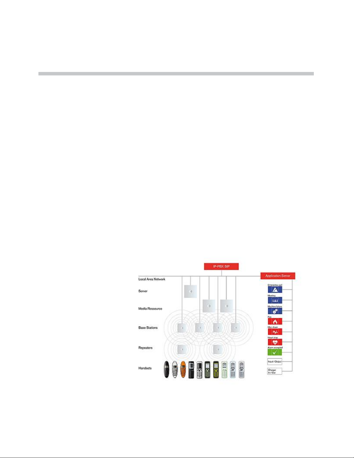
This section provides a description of the KWS6000 solution.
A typical KWS6000 configuration includes a number of the following
components, in addition to the KWS6000:
• Media resources
• Base stations
• Repeaters
• Handsets and accessories
Figure 2-1 Overview of the Whole Solution
2–1
Page 18

KIRK Wireless Server 6000 Installation and Configuration Guide
This section provides information about:
• “Components of the KIRK Wireless Server 6000 Solution” on page 2-2
• “Requirements for the KIRK Wireless Server 6000 Solution” on page 2-7
• “Installation Prerequisites” on page 2-11
Components of the KIRK Wireless Server 6000 Solution
This section provides information about:
• “KIRK Wireless Server 6000” on page 2-2
• “Wireless Bands” on page 2-3
• “KIRK Media Resource” on page 2-3
• “KIRK Base Station” on page 2-4
• “KIRK Repeater” on page 2-5
• “KIRK Handset” on page 2-6
• “KIRK Maintenance Software” on page 2-7
• “Administrative Computer” on page 2-7
KIRK Wireless Server 6000
Below you will find an overview of the system capacity of the KWS6000.
Table 2-1 Overview of System Capacity
Description Capacity
Max. number of base stations.
Note: A minimum of 1 base station is required, as the KWS6000
does not have a built-in radio.
Max. number of simultaneous calls on each base station 11
Max. number of repeaters on each base station 6
Max. number of simultaneous calls on a KWS6000/media resource
(G.711)
Max. number of media resources 32
Max. number of simultaneous calls with 32 media resources 1024
255
32
2–2
Page 19

Introduction to KIRK Wireless Server 6000
Table 2-1 Overview of System Capacity
Description Capacity
Wireless Bands
Max. number of simultaneous calls on each KWS6000/media
resource with Codec Module
Max. number of simultaneous calls with 32 media resources with
Codec Module.
24
768
Note: If the Codec Module is used, it is recommended to
install it in al media resources.
Max. number of registered handsets
4096
The KWS6000 controls the wireless infrastructure. It manages media
resources, base stations, repeaters and the IP interface to the call handler.
The communication protocol between the KWS6000 and the call handler is SIP
A KWS6000 is installed directly on the LAN and must be managed as part of
the corporate network.
For more information about the KWS6000, refer to “Deploying KIRK Wireless
Server 6000” on page 3-1, “Installing KIRK Wireless Server 6000 and KIRK
Media Resource” on page 4-1 and “Configuring KIRK Wireless Server 6000”
on page 10-1.
The wireless solution supports two wireless bands, allowing operation in
various countries and regions. Supported wireless bands are:
• ETSI DECT (1880-1900 Mhz), referred to as DECT
• USA DECT (1920-1930 Mhz), referred to as 1G9
The wireless band used by a KWS6000 solution is determined by the base
stations and handsets ordered with the solution.
KIRK Media Resource
The media resource performs media conversion between the call handler and
the KWS6000 and is the media termination point for incoming and outgoing
calls.
A maximum of 32 media resources can be added to KWS6000. Each media
resource adds 32 voice channels to the system. It furthermore handles the
media stream from the SIP server and voice is thus distributed from the KIRK
Media Resource to the KIRK IP Base Station. Adding 32 media resources
makes it possible to have 1024 calls at the same time.
Note
KWS6000 contains one media resource.
2–3
Page 20

KIRK Wireless Server 6000 Installation and Configuration Guide
Codec Module
It is possible to install a Codec Module in the media resource. The Codec
Module adds a number of codecs, allowing the wireless server to interface to
G.729A/G.723.1 and other codec standards.
Note
KIRK Base Station
When installing a Codec Module, the media resource only adds 24 voice
channels to the system. Adding 32 media resources with codec modules
makes it possible to have 768 calls at the same time.
For more information about media resources, refer to “Installing KIRK
Wireless Server 6000 and KIRK Media Resource” on page 4-1 and
“Configuring KIRK Media Resources” on page 11-1.
For more information about installing the Codec Module, refer to “Installing
KIRK Codec Module” on page 5-1.
The base stations are positioned in the area to send and receive calls between
the wireless server and the handset. The base station contains internal
antennas and handles 11 speech channels simultaneously. A base station is
able to synchronize with other base stations. When the base station is
synchronized with other base stations, a person speaking in a handset can
move between base stations without any interference.
Transmission length is up to 100 meters/329 feet according to IEEE 802.3u on
a twisted pair cable, e.g. cat.5e. The base station is a class 1 PoE device (802.3af)
and must be powered accordingly (maximum power supply consumption
3.0W according to PoE 802.3af). The radius coverage of the base station is up
to 90 meters/295 feet indoor and up to 300 meters/984 feet outdoor, with a
handset in line-of-sight.
2–4
Coverage area decreases depending on choice of building materials and
obstructive elements. To ensure proper coverage in the areas required, it is
necessary to conduct a site survey and deployment by certified technicians.
For more information about deployment, refer to the Deployment Guide
accompanying the Deployment Kit.
For more information about the base station, refer to “Installing KIRK Base
Station” on page 6-1 and “Configuring KIRK Base Station” on page 12-1.
Page 21

KIRK Repeater
Introduction to KIRK Wireless Server 6000
The repeater can be used to extend the coverage area in a wireless solution.
Depending on the repeater type, it can be mounted either on the wall or on the
ceiling. The wireless repeater is used in areas with limited voice traffic, where
cabling is difficult. The repeater does not increase the number of traffic
channels, but increases the coverage area established with the base station. Up
to three repeaters can be placed in cascade formation directing coverage in a
certain direction.
The base station can support up to 6 repeaters.
For more information about the repeater, refer to “Installing KIRK Repeater”
on page 7-1.
2–5
Page 22

KIRK Wireless Server 6000 Installation and Configuration Guide
KIRK Handset
The handset is a lightweight, ergonomically designed wireless unit that
includes an LCD display and keypad.
The handset is a portable unit compatible with DECT GAP standard.
The handset is designed to provide the subscriber with most of the features
available for a wired phone, in addition to its roaming and handover
capabilities.
The KWS6000 supports up to 4096 registered handsets.
For more information about the handset, refer to “Preparing KIRK Handset for
Use” on page 8-1, “KIRK Handset Registration and Subscription” on page 13-1
and “KIRK Handset Management” on page 14-1.
Auto Login and Handover
Auto login refers to the ability to log on to more than one system, enabling you
to use the same handset on up to 10 different systems. If a handset is
subscribed to two or more systems, you can use Auto Login type A or Auto
Login type B to change between the systems automatically:
• Auto Login type A is used if a handset is subscribed to two or more
systems. Auto Login A should only be used in separate systems without
overlaps.
• Auto Login type B is used if a handset is subscribed to two systems only.
Auto Login B can be used in separate systems which are overlapping each
other.
Note
Auto Login type B is only supported in 4020/4040/4080 Handsets.
For more information about Auto Login, refer to “Subscribing KIRK
Handsets” on page 13-3.
Handover refers to the ability to move between the coverage areas of different
radio units on the same system while talking, without interruptions in the
conversation.
KIRK SIO Application Interface
The SIO Application Interface is a communication platform allowing text
messaging between the wireless server and a handset. With the SIO API,
which is a fundamental part of all our solutions, and a third party application
program, the customer is offered a wide range of usage opportunities in a
variety of vertical markets.
2–6
Page 23

KIRK Maintenance Software
The following software application for the installation and maintenance of the
KWS6000 Solution is provided:
• ServiceTool
Used for programming of the repeater, adjustment of the handset and
software download to repeater/handset.
Introduction to KIRK Wireless Server 6000
Note
ServiceTool is not used for adjustment of the 5020 Handset.
The ServiceTool application can be downloaded from
www.polycom.com.
Administrative Computer
An administrative computer is required for configuration and maintenance of
the KWS6000, media resource and base station. This computer may be
temporarily connected directly to the device or to the network. A dedicated
computer is not required.
Requirements for the KIRK Wireless Server 6000 Solution
This section provides information about the environmental and electrical
requirements and software requirements for the KWS6000 solution.
KIRK Wireless Server 6000/KIRK Media Resources
Note
Environmental Requirements
The installation area must:
• be clean, free of traffic and excess dust, dry, and well ventilated
• be within the temperature ranges of 10°C and 40°C/50°F and 104°F
• be between 20% and 80% non-condensing relative humidity
The installation area must be of sufficient height from the floor to prevent
water damage.
2–7
Page 24

KIRK Wireless Server 6000 Installation and Configuration Guide
Electrical Requirements
The following electrical requirements must be met:
• Power consumption: 8V/500 mA
• Typical power consumption: 5W per unit
• The supplied power for the AC adaptor power supply must be 110 to 240
ac nominal, 50/60 Hz.
• Power supply must be LPS
KIRK Base Stations and KIRK Repeaters
Environmental Requirements
• Avoid installing base stations and repeaters on large concrete or marble
columns because these columns affect radio coverage. If possible, place the
base station a minimum of one meter/3.3 feet from these types of columns.
• Do not install a base station or repeater with the antenna housings near
metal objects. Be careful not to damage existing wiring or panels.
• Do not position base stations and repeaters in ducts, plenums, or hollow
spaces used to transport environmental air except where the duct, plenum
or hollow space is created by a suspended ceiling having lay-in panels.
When you need more than one base station in a cell to meet traffic
requirements, position the base stations at the same cell center.
• Keep the base station and repeater away from steel constructions.
• Do not position base stations and repeaters directly on metallic surfaces. If
possible, place the base station a minimum of one meter/3.3 feet from
these types of surfaces.
• Do not position base station and repeaters behind furniture.
• Only position base stations and repeaters where the signal is needed.
• The installation area must be clean, free of traffic and excess dust, dry, and
well ventilated.
• The installation area must be within the temperature ranges of 10°C and
40°C/50°F and 104°F.
• The installation area must be between 20% and 80% non-condensing
relative humidity.
2–8
Page 25

Introduction to KIRK Wireless Server 6000
• Minimum distance between two base stations varies depending on
material and construction of buildings, but there must always be
synchronization chains and radio coverage overlap between the two base
stations or handover between radio units. The time it takes a person to
cross the common coverage area must be 10 seconds or more, as the
handset needs time to scan for an alternative base station.
Electrical Requirements for Base Station
The following electrical requirements must be met:
• The base station operates on standard twisted pair ethernet cable - e.g.
minimum Cat.5e - to prevent disturbances from other equipment.
• Maximum power supply consumption is 3.0W (IEEE 802.3af class 1
device).
• The max. radiated output power for the antenna is 10mW e.i.r.p/channel.
Electrical Requirements for Repeater
• The supplied power (power supply) for the charger must be 110 V to 120
V ac nominal (or 220 V to 230 V ac nominal), 50/60 Hz.
2–9
Page 26

KIRK Wireless Server 6000 Installation and Configuration Guide
KIRK Handsets
Environmental Requirements
• The area where the handset is used must be within the temperature ranges
of 0°C and 40°C/32°F and 104°F.
• For correct battery charging, the room temperature must be between 0°C
and 25°C/32°F and 77°F. Therefore, the handset must not be placed in
direct sunlight. The battery has a built-in heat sensor which will stop
charging if the battery temperature is too high.
• For battery information, refer to “Installing Battery” on page 8-4.
• The area where the handset is used must be between 20% and 80%
non-condensing relative humidity.
Electrical Requirements
The following electrical requirement must be met:
• The supplied power (power supply) for the charger must be 110 V to 120
V ac nominal (or 220 V to 230 V ac nominal), 50/60 Hz.
KIRK Maintenance Software
This section describes the computer requirements to run the installation and
maintenance tools of the handset and repeater.
Software Requirements
• OS: Windows 2000 (SP4), Windows XP (SP2), Windows Vista
• CPU: Minimum 400MHz (2000/XP), 1GHz (Vista)
• RAM: Minimum 256 MB (2000/XP), 1 GB (Vista)
• GPU/Display: XGA (1024x768)
• Harddisk: Minimum recommended harddisk size by OS and other
installed applications + 25 MB free space for the application.
Note
Depending on other applications running on the system, CPU, RAM and
harddisk may vary.
2–10
Page 27

Installation Prerequisites
Introduction to KIRK Wireless Server 6000
Note
Ensure that a site survey and deployment have been conducted and that the
installer has access to these plans before proceeding any further. For more
information about deployment, refer to “Deploying KIRK Wireless Server
6000” on page 3-1.
Before you start the installation you need to find the following information
and perform the following tasks:
• ARI codes (serial numbers) for the KWS6000 (see label on the rear of the
KWS unit)
• Serial numbers for handsets. Refer to “Retrieving the Serial Number of the
KIRK Handset” on page 8-10.
• AC codes (authentication codes)
The AC is a customer-defined optional subscription pin code of a
maximum of eight digits for the individual handset. The AC can be used
when connecting the handset to the KWS.
• Repeaters:
Mark each repeater with the number of the related base station. This way
you can easily configure the system on site.
• Handsets:
To use the handsets, you must first install the radio infrastructure, e.g.
base stations and repeaters to transmit and receive radio signals to and
from the handsets. There are no direct connections between the handset
and the system. For more information about base station and repeater
installation, refer to “Installing KIRK Base Station” on page 6-1 and
“Installing KIRK Repeater” on page 7-1.
• Charging battery
When charging the handset battery for the first time, leave the handset in
the charger for 14 - 16 hours to ensure that the battery is fully charged and
the handset ready for use. Refer to “Charging KIRK Handsets” on
page 8-6.
2–11
Page 28

KIRK Wireless Server 6000 Installation and Configuration Guide
2–12
Page 29

Deploying KIRK Wireless Server 6000
Before you install the KWS6000 solution, it is necessary to perform a complete
site survey and determine the exact location of KWS6000, base stations,
repeaters and number of handsets required.
A well planned installation should start with an RF coverage site survey. A site
survey is designed to determine the optimal location for base stations and
repeaters and the amount of wireless voice traffic to be supported by the
installation (i.e., how many handsets must maintain voice conversations at the
same time, in any given area).
3
Due to the unexpected nature of RF propagation in an indoor environment, an
actual on-site test must be performed before the installation is complete. While
an extensive guide to effective RF coverage planning is outside the scope of
this manual, the following points should be taken into consideration when
planning the site, prior to base station and repeater installation:
• The base station/repeater provides typical RF coverage of up to 50
meters/164 feet in a typical indoor office environment and up 300
meters/984 feet in an open area (line-of-sight), extending in all directions
from the base station/repeater. The exact coverage range depends on the
building architecture, wall material and surroundings.
• The wireless solution can support a maximum of 4096 handsets.
• The wireless solution supports a maximum of 255 base stations.
• Handset handover: handsets can move between coverage areas of base
stations and repeaters while receiving continuous service and maintaining
conversations in progress.
• For efficient handover of conversations between base stations, deploy base
stations with wide overlap between them (i.e., plan for some areas to be
covered by more than one base station). Overlaps are necessary to
maintain seamless handover and to establish synchronization chains. A
good example may be a cafeteria during lunch hour where temporary
3–1
Page 30

KIRK Wireless Server 6000 Installation and Configuration Guide
concentrations of handsets may occur. The overlap carries the excess call
load to adjacent base station to provide uninterrupted services to
subscribers.
• Typically, installations such as office buildings, hotels and hospitals
should be equipped with base stations/repeaters on several floors to
create uniform and complete RF coverage.
• Open areas can be covered with a sparse network of base stations. In such
applications, the base stations/repeaters cover an extended range due to
the extended line-of-sight RF propagation capability.
• Ensure that there is not a residential DECT system (home DECT) on the
site.
This section provides information about:
• “Recommendations for KIRK Base Station/KIRK Repeater Placement” on
page 3-2
• “Deployment of a KIRK Wireless Server 6000 Multi-Cell” on page 3-3
Recommendations for KIRK Base Station/KIRK Repeater Placement
• In large halls, the base station/repeater (wall) should be installed
vertically in the middle of the space below the drop ceiling.
• In corridors, the base station/repeater (wall) should be installed vertically
preferably at corridor intersections where propagation patterns follow the
corridor patterns. The base station/repeater should point towards the
corridor and preferably in the middle height between the floor and the
actual ceiling. In case there are high objects in the area, the base
station/repeater (wall) should be installed above those objects but still
kept distant from the ceiling.
• The repeater (ceiling) should be installed in the middle of corridors and
small rooms.
• In multi-story buildings, base stations/repeaters may be installed on
opposite sides of the floors to take advantage of the floor-to-floor
coverage. The coverage design cannot rely entirely on floor-to-floor
propagation; each case must be verified due to variations in local
attenuation patterns.
• If the building contains a central open space area with windows to the
other areas, base stations/repeaters may be installed in this open space to
provide a good coverage for the rooms in the inner circle on all floors (e.g.
hotels).
3–2
Page 31

Deploying KIRK Wireless Server 6000
• If a base station/repeater (wall) hangs vertically on a wall, the RF coverage
in front of the base stations/repeaters is twice as large as the coverage at
the rear. When a base station/repeater is installed on the outside of an
outer wall, the RF coverage behind it is strongly attenuated by the wall.
• Base stations/repeaters should not be installed near large metallic objects.
• Reinforced concrete structures have a high attenuation factor inside the
building. They decrease the RF coverage range of the base
stations/repeaters and therefore requires a higher number of base
stations/repeaters in the building. Lighter types of construction require
fewer base stations since attenuation figures are considerably lower.
0
Deployment of a KIRK Wireless Server 6000 Multi-Cell
Sync over Air
Note
Note
This section only contains deployment information specific to the
KWS6000. For more information about deployment in general, refer to the
Deployment Guide accompanying the Deployment Kit. The Deployment
Guide provides instructions on how to use the Deployment Kit to
determine the most suitable locations for the different radio units.
As a user moves from one base station radio coverage area to another, the call
must be handed over to the next radio unit. To create handover between radio
units it is necessary to establish synchronization chains. For more information
about synchronization chains, refer to “Examples of Synchronization Chains”
on page 3-4. If the synchronization between radio units is lost, then handover
is not possible and ongoing calls will be terminated.
Each base station must be placed within the radio coverage area of at least
one other base station or repeater (radio units).
3–3
Page 32

KIRK Wireless Server 6000 Installation and Configuration Guide
Examples of Synchronization Chains
Certain rules must be taken into consideration when establishing
synchronazation chains:
• The distance over which synchronization can take place is limited to a
distance similar to a loss of max. 25 dB. If the loss of signal is higher than
25 dB, there is no guarantee that synchronization is stable.
Note
Note
Note
It is recommended that a base station synchronizes with at least two other
radio units, that an alternative sync way is defined to ensure system
redundancy. If the primary sync way is not working, then the alternative
sync way takes over and the synchronization chain is not broken.
Synchronization chains for the KWS6000 Solution can be made with base
stations and repeaters.
As you can only configure a repeater to synchronize on one radio ID, it is
not possible to define alternative sync ways for repeaters.
As the KWS6000 uses the DECT interface to synchronize on, one base station
is configured as the Sync Master.
This section provides information about:
• “Sync Chain With One Sync Master (Primary Sync Ways)” on page 3-5
• “Sync Chain With Alternative Sync Ways” on page 3-6
• “Sync Chain With and Without Alternative Sync Ways” on page 3-9
3–4
Page 33

Deploying KIRK Wireless Server 6000
Sync Chain With One Sync Master (Primary Sync Ways)
Figure 3-1 Synchronization Chain
• The synchronization chain must always overlap with the base station to
sync on.
• No.0 is the Sync Master (can be numbered 0-255).
• Other radio units are connected to the Sync Master through the
synchronization chain.
• If one of the radio units in the synchronization chain is not working, then
the synchronization chain is broken and the system will be unstable.
Figure 3-2 Synchronization Chain Layout without Alternative Sync Ways
• No. 0 is the Sync Master (can be numbered 0-255).
Note: It is recommended to place the Sync Master in the middle of the
building.
• Green line: Shows the primary sync ways.
• Brown line: Only handover overlap is needed.
Note: It is recommended to make a site planner. Every base station must
be numbered with Radio ID, Primary sync Radio ID, and Alternative
sync Radio ID.
3–5
Page 34

KIRK Wireless Server 6000 Installation and Configuration Guide
Sync Chain With Alternative Sync Ways
Figure 3-3 Synchronization Chain with Alternative Sync Ways
• No. 0 is the Sync
Master (can be numbered 0-255).
• No. 10 and No. 20: Primary and alternative sync on No. 0.
• No. 11: Primary sync on No. 10 and alternative sync on No. 21.
• No. 21: Primary sync on No. 20 and alternative sync on No. 11.
3–6
Page 35

Deploying KIRK Wireless Server 6000
In the example below, base station No. 10 is down. As a consequence, base
station No. 11 must use the alternative sync way on No. 21.
Figure 3-4 Synchronization Chain with Alternative Sync Ways
• No. 0 is the Sync Master (can be numbered 0-255).
• No. 10 and No. 20: Primary and alternative sync on No. 0.
• No. 11: Primary sync on No. 10 and alternative sync on No. 21.
• No. 21: Primary sync on No. 20 and alternative sync on No. 11.
Figure 3-5 Synchronization Chain with Alternative Sync Ways
• No. 0 is the Sync Master (can be numbered 0-255).
• No. 10, No. 20, No. 30, and No. 40: Primary and alternative sync on No. 0.
• No. 11: Primary sync on No. 10 and alternative sync on No. 21.
• No. 21: Primary sync on No. 20 and alternative sync on No. 11.
• No. 31: Primary sync on No. 30 and alternative sync on No. 41.
• No. 41: Primary sync on No. 40 and alternative sync on No. 31.
3–7
Page 36

KIRK Wireless Server 6000 Installation and Configuration Guide
Figure 3-6 Synchronization Chain Layout with Alternative Sync Ways
• No. 0 is the Sync Master (can be numbered 0-255).
Note: It is recommended to place the Sync Master in the middle of the
building.
• Green line: Shows the primary sync ways.
• Red line: Shows the alternative sync ways.
Note: It is recommended to make a site planner. Every base station must
be numbered with Radio ID, Primary sync Radio ID, and Alternative
sync Radio ID.
3–8
Page 37

Deploying KIRK Wireless Server 6000
Sync Chain With and Without Alternative Sync Ways
Figure 3-7 Synchronization Chain With and Without Alternative Sync Ways
• No. 0 is the Sync
Master (can be numbered 0-255).
• No. 10 and No. 20: Primary and alternative sync on No. 0.
• No. 11, No. 12 and No. 13: Only primary sync.
• No. 14 and No. 15: Primary sync and alternative sync.
• No. 21, No. 22 and No. 23: Only primary sync.
• No. 41: Primary sync on No. 40 and alternative sync on No. 31.
• No. 11 and No. 21: Only handover overlap (Marked with green).
3–9
Page 38

KIRK Wireless Server 6000 Installation and Configuration Guide
Figure 3-8 Synchronization Chain With Repeaters
• No. 0 is the
Sync Master (can be numbered 0-255).
• No. 10 and No. 20: Primary and alternative sync on No. 0.
• No. 74, No. 138 and No. 202: Repeater - no alternative sync possible.
• No. 14 and No. 15: Primary sync and alternative sync on repeater.
• No. 84, No. 148 and No. 212: Repeater - no alternative sync possible.
• No. 24 and No. 25: Primary sync and alternative sync.
• No. 74 and No. 84: Only handover overlap (Marked with green).
3–10
Page 39

4
Installing KIRK Wireless Server 6000 and KIRK Media Resource
This section provides a description of the KWS6000 and media resource. The
section also provides information about resetting the KWS6000 hardware
using the Reset button on the KWS6000/media resource faceplate.
Note
The installation of a media resource is optional. Installation of a media
resource will augment the number of simultaneous voice calls supported by
a stand-alone server.
Before you install the equipment, ensure that a site planner defines the
locations of the KWS6000 and media resources.
This section contains the following information:
• “Description of KWS6000/KIRK Media Resource” on page 4-2
• “Installing the KWS6000/KIRK Media Resource” on page 4-7
4–1
Page 40

KIRK Wireless Server 6000 Installation and Configuration Guide
Description of KWS6000/KIRK Media Resource
This section contains information about:
• “KWS6000 Types and Part Numbers” on page 4-2
• “KWS6000/KIRK Media Resource Appearance and Components” on
page 4-3
• “KWS6000/KIRK Media Resource LED Indicators” on page 4-5
• “KWS6000/KIRK Media Resource - Reset Button” on page 4-6
Types and Part Numbers
KWS6000 Types and Part Numbers
The KWS6000 contains RF circuitry that comply with the local band standards:
ETSI DECT and USA DECT 6.0. The table below includes a list of available
KWS6000 and their part numbers.
Table 4-1 KIRK Wireless Server 6000 Part Numbers
Variants of KIRK Wireless Server 6000 Part Number
KIRK Wireless Server 6000 1.8/1.9 GHz
• with SIP Protocol
For more information about SIP variants go to
www.polycom.com
02344100
KIRK Media Resource Types and Part Numbers
The media resource contains RF circuitry that comply with the local band
standards: ETSI DECT and USA DECT 6.0. The table below includes a list of
available media resources and their part numbers.
Table 4-2 KIRK Media Resource Part Numbers
Variants of KIRK Media Resources Part Number
KIRK Media Resource 1.8/1.9 GHz
• with SIP Protocol
02344200
4–2
Page 41

Installing KIRK Wireless Server 6000 and KIRK Media Resource
KWS6000/KIRK Media Resource Appearance and Components
The KWS6000/media resource front cover includes the following:
• LED that indicates the operating status of the unit
Figure 4-1 KWS6000/Media Resource - Front view
LED
4–3
Page 42

KIRK Wireless Server 6000 Installation and Configuration Guide
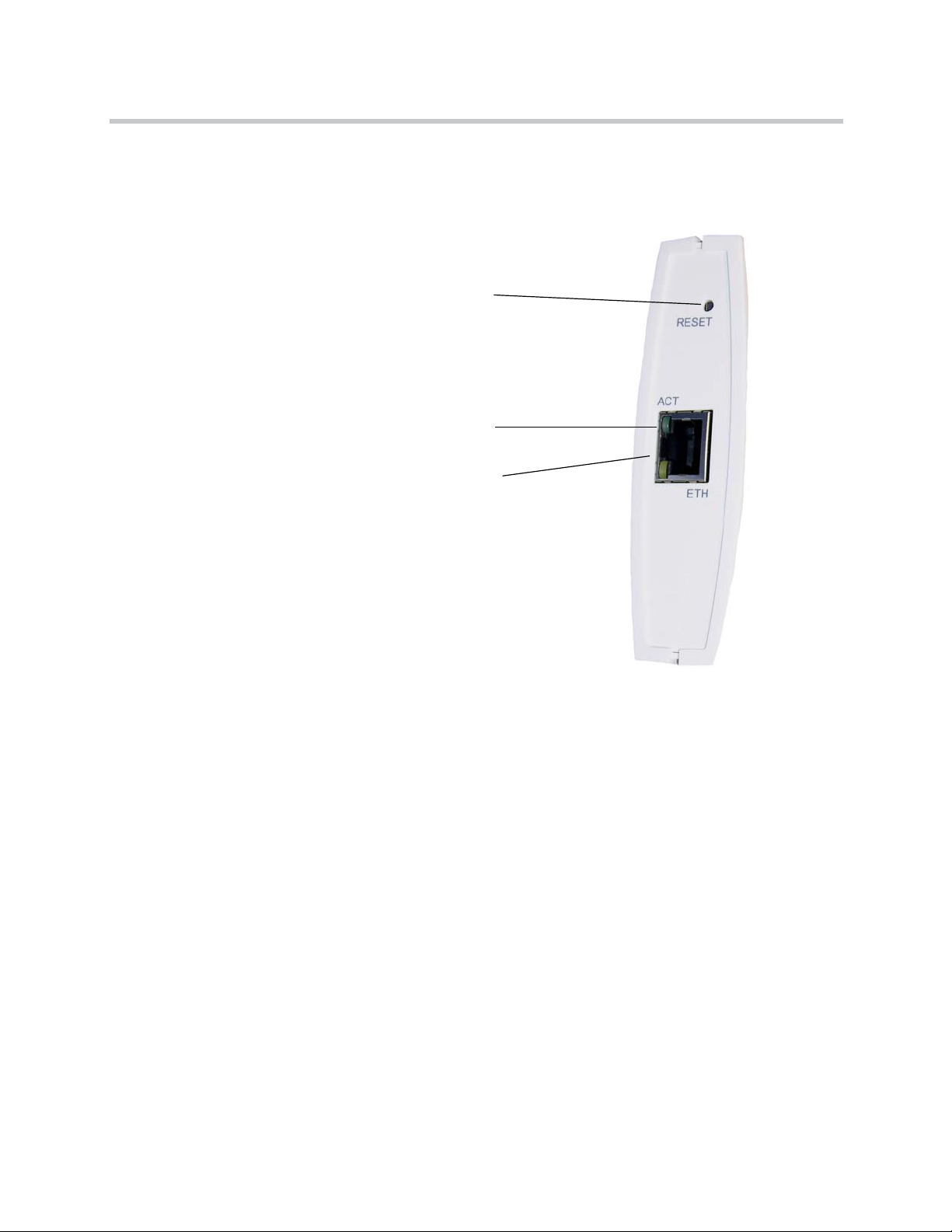
The KWS6000/media resource faceplate includes the following (see figure
below).
Figure 4-2 KWS6000/Media Resource - Faceplate
Reset Button
ETH Port
LINK/Activity Indicator
Power Supply
Power Indicator
For information about the Reset button, refer to “Resetting the
KWS6000/KIRK Media Resource Hardware” on page 4-6.
4–4
Page 43

Installing KIRK Wireless Server 6000 and KIRK Media Resource
KWS6000/KIRK Media Resource LED Indicators
Front Cover
The KWS6000/media resource front cover has one indicator describing the
faults and failures of the device. The indicator is off when the KWS6000/media
resource is not powered. The LED flashes when the KWS6000/media resource
initializes. The indicator is on when the KWS6000/media resource is
operating.
Table 4-3 LED Indicator Description - Front Cover
LED Indicator Meaning
Steady green OK and idle
Slow green flashing OK and active voice call
Fast green flashing Active, in operation with the maximum active
connections (busy)
Slow red flashing Missing media resource or base station (if it is a
media resource: missing connection to
KWS6000)
Fast red flashing Error
Steady red Reset/shutdown in progress
Steady red for 5 seconds
followed by fast red flashing
Reset to factory settings
Faceplate
Table 4-4 LED Indicator Description - Faceplate
LED Indicator Meaning
LINK/Activity Indicator - green Link layer software has established
connection
LINK/Activity Indicator - green
flashing
Power Indicator - green KWS6000 is connected to Power
Activity
4–5
Page 44

KIRK Wireless Server 6000 Installation and Configuration Guide
KWS6000/KIRK Media Resource - Reset Button
It is possible to restart or reset the KWS6000/media resource by pressing the
Reset button on the faceplate of the KWS6000/media resource. For description
of the faceplate, refer to “Faceplate” on page 4-5.
Resetting the KWS6000/KIRK Media Resource Hardware
This section contains a description of the different actions that take place when
pressing the Reset button.
Table 4-5 Reset Button Description
Press button Action
Short press (2 to 5 sec.) System restarts when button is released.
Long press (5 to 9 sec.)
until front LED flashes
red, then release button
Resets the system to factory default settings (original
IP settings and empty user data base) and restarts the
system.
Firmware version is not affected.
4–6
Page 45

Installing KIRK Wireless Server 6000 and KIRK Media Resource
Installing the KWS6000/KIRK Media Resource
The KWS6000/media resource is suitable for mounting indoors on a wall.
1 Mount the KWS6000/media resource on the wall, using the anchors and
screws provided.
Note: When you place the KWS6000/media resource on the screws,
ensure that the screws do not touch the printed circuit board.
Figure 4-3 KWS6000/Media Resource Wall Mounting
2 Connect the wire into the RJ45 plug on the KWS6000/media resource.
4–7
Page 46

KIRK Wireless Server 6000 Installation and Configuration Guide
4–8
Page 47

Installing KIRK Codec Module
This section provides a description of the Codec Module and describes how to
unpack and install it in a media resource. The Codec Module adds a number
of codecs, allowing the wireless server to interface to G.729A/G.723.1 and
other codec standards.
5
Note
When installing a Codec Module, the media resource only adds 24 voice
channels to the system. Adding 32 media resources with codec cards makes
it possible to have 768 calls at the same time.
For more information about media resources, refer to “Installing KIRK
Wireless Server 6000 and KIRK Media Resource” on page 4-1.
This section contains the following information:
• “Description of KIRK Codec Module” on page 5-2
• “Installing the KIRK Codec Module” on page 5-3
5–1
Page 48

KIRK Wireless Server 6000 Installation and Configuration Guide
Description of KIRK Codec Module
This section contains information about:
• “KIRK Codec Module Type and Part Number” on page 5-2
• “KIRK Codec Module Appearance” on page 5-2
KIRK Codec Module Type and Part Number
Table 5-1
Codec Module for KIRK Wireless Server 6000 Part Number
KIRK Codec Module 1.8/1.9 GHz (conforms with standard
DECT markets)
KIRK Codec Module Part Number
KIRK Codec Module Appearance
Figure 5-1 Codec Module
02344300
5–2
Page 49

Installing the KIRK Codec Module
This section describes how to install the Codec Module in a media resource.
Installing KIRK Codec Module
Note
Installation must be performed by authorized personal only and must be
performed at an approved ESD workstation.
How to install the Codec Module
1 Power off the media resource.
2 Remove the cover of the media resource carefully:
— Place the media resource face down on a desk.
— Apply sufficient pressure to the tabs located at each of the four corners
of the unit while gently lifting the cover from the chassis.
— Once separated, set the front cover aside in a safe location.
3 Snap the two support posts into the printed circuit board of the media
resource.
4 Carefully insert the Codec Module into the Codec Module connector and
the two support posts on the printed circuit board.
Figure 5-2 Installing Codec Module on Pinted Circuit Board
5 Replace the cover by aligning the tabs with the proper positions and
gently press the cover onto the chassis until the tabs lock into place.
6 Connect the LAN cable to the media resource.
7 Power up the media resource.
5–3
Page 50

KIRK Wireless Server 6000 Installation and Configuration Guide
8 When accessing the web based Administration Page of the KWS6000
under Administration/Media Resource, you can now see that more
codecs are available.
For information about accessing the web based Administration Page, refer
to “Accessing the Web Based Administration Page” on page 10-2.
5–4
Page 51

Installing KIRK Base Station
This section provides information about the base station and how to install it.
Before you install the equipment, ensure that a site planner defines the location
of the base stations.
This section includes information about:
• “KIRK Base Station Description” on page 6-1
• “Installing the KIRK Base Station” on page 6-5
• “Recording the Installation Information” on page 6-6
6
KIRK Base Station Description
This section contains information about:
• “KIRK Base Station provides RF Channels to KIRK Handsets” on page 6-1
• “KIRK Base Station Types and Part Numbers” on page 6-2
• “KIRK Base Station Appearance and Components” on page 6-2
• “KIRK Base Station LED Indicators” on page 6-4
• “KIRK Base Station - Reset Button” on page 6-5
KIRK Base Station provides RF Channels to KIRK Handsets
The base station is a compact device that contains RF circuitry and
transmit/receive antennas. The main function of the base station is to provide
audio and data communication between the handsets and the KWS6000. The
base station supports 11 RF channels for DECT or USA DECT bands.
Note
The base station is also termed by some manufacturers as the RFP (Radio
Fixed Part).
6–1
Page 52

KIRK Wireless Server 6000 Installation and Configuration Guide
The RF communication is provided according to the band standard at the site:
• Base station - DECT provides 11 RF channels of 1.8 GHz, DECT standard,
used in Europe, Australia and South America.
• Base station - USA DECT provides 11 RF channels of the 1.9 GHz, USA
DECT standard, used in North America.
KIRK Base Station Types and Part Numbers
The base station contain RF circuitry that comply with the local band
standards: UPCS, DECT, or ETSI DECT. The table below includes a list of
available base stations and their part numbers.
Table 6-1 KIRK Base Station Part Numbers
Variants of KIRK Base Stations Part Number
KIRK Base Station 12 1.8 GHz (conforms with standard
DECT markets)
KIRK Base Station 12 1.9 GHz (for North America) 02337301
KIRK Base Station Appearance and Components
The base station front cover includes the following:
• LED that indicates the operating status of the unit
Figure 6-1 Base Station - Front view
02337300
LED
6–2
Page 53
Installing KIRK Base Station
The base station faceplate includes the following (see figure below).
Figure 6-2 Base Station - Faceplate
Reset Button
LINK/Activity Indicator
ETH Port (Power supply
by PoE)
For information about the Reset button, refer to “Resetting the KIRK Base
Station Hardware” on page 6-5.
6–3
Page 54

KIRK Wireless Server 6000 Installation and Configuration Guide
KIRK Base Station LED Indicators
Front Cover
The base station front cover has one indicator describing the base station faults
and failures. The indicator is off when the base station is not powered. The
LED flashes when the base station initializes. The indicator is on when the base
station is operating.
Table 6-2 LED Indicator Description - Front Cover
LED Indicator Meaning
Steady green OK and idle
Slow green flashing OK and active voice call
Fast green flashing Active, in operation with the
Slow red flashing Missing media resource or base
maximum active connections
(busy)
station (if it is a media resource:
missing connection to KWS6000)
Fast red flashing Error
Steady red Reset/shutdown in progress
Steady red for 5 seconds
followed by fast red flashing
Reset to factory settings
Faceplate
Figure 6-3 LED Indicator Description - Faceplate
LED Indicator Meaning
LINK/Activity Indicator - green Link layer software has
established connection
LINK/Activity Indicator - green
flashing
Power Indicator - green KWS6000 is connected to Power
Activity
6–4
Page 55

KIRK Base Station - Reset Button
It is possible to restart or reset the base station by pressing the Reset button on
the faceplate of the base station. For description of the faceplate, refer to
“Faceplate” on page 6-4.
Resetting the KIRK Base Station Hardware
This section contains a description of the different actions that take place when
pressing the Reset button.
Table 6-3 Reset Button Description
Press button Action
Short press (2 to 5 sec.) System restarts when button is
Installing KIRK Base Station
released.
Long press (5 to 9 sec.) until
front LED flashes red, then
release button
Resets the system to factory default
settings (original IP settings and
empty user data base) and restarts
the system.
Firmware version is not affected.
Installing the KIRK Base Station
The base station is suitable for mounting indoors on a wall.
Note
Wall Mounted (Vertical) Installation RF Coverage
Before beginning the installation, determine the position of the base station
for best coverage. The coverage depends on the construction of the
building, architecture, and the choice of building materials. Refer to
“Environmental Requirements” on page 2-8 for more information about
environmental requirements for base stations.
For best RF coverage, the base station must be mounted vertically on walls.
The antennas must always be kept perpendicular to the floor.
Caution:
The base station must not be installed at any angle other than vertical. If the
base station is placed upside-down, the coverage area of the base station is
decreased by 40 - 50% and it might not transmit or receive effectively.
6–5
Page 56

KIRK Wireless Server 6000 Installation and Configuration Guide
Caution:
Do not mount the base station on soft surfaced walls such as those covered
with canvas, metal or sponge-like materials.
1 Mount the base station on the wall using the anchors and screws
accompanying the product.
Note: When you place the base station on the screws, ensure that the
screws do not touch the printed circuit board.
Figure 6-4 Base Station Wall Mounting
2 Connect the RJ45 plug to the ethernet connector at the bottom of the base
station.
00
Figure 6-5 Base Station - Ethernet Connector
Recording the Installation Information
After completing the installation of the base stations, record the location of
each base station and add a descriptive text in the Administration Page of the
KWS6000 under Administration/Base stations.
6–6
Page 57

Installing KIRK Repeater
This section provides information about the repeater and how to unpack and
install it. Installing repeaters requires a software installation as well as a
hardware installation.
Before you install the equipment, ensure that a site planner defines the location
of the repeaters.
This section includes information about:
• “KIRK Repeater Description” on page 7-1
• “Installing the KIRK Repeater” on page 7-4
• “Recording the Installation Information” on page 7-6
7
• “Checking Indicators” on page 7-6
• “Powering the KIRK Repeater” on page 7-6
• “Programming a KIRK Repeater with the KIRK Programming Kit” on
page 7-7
KIRK Repeater Description
This section contains information about:
• “KIRK Repeater provides RF Channels to KIRK Handsets” on page 7-1
• “KIRK Repeater Types and Part Numbers” on page 7-2
• “KIRK Repeater - Appearance and Components” on page 7-3
• “KIRK Repeater LED Indicators” on page 7-3
KIRK Repeater provides RF Channels to KIRK Handsets
The KIRK Repeater is a building block to be used to extend the coverage area
in a KIRK solution. The repeater does not increase the number of traffic
channels, however it provides a larger physical spreading of the traffic
channels and thereby increases the coverage area established with the KIRK
7–1
Page 58

KIRK Wireless Server 6000 Installation and Configuration Guide
Base Stations.The repeaters are mainly used in areas with limited traffic. The
KIRK Repeater is available with either 2 or 4 voice channels. It is wireless and
does not need physical connection to the KIRK Wireless Server, making it very
easy to install. The repeaters can be supplied with an external antenna making
it possible to create radio coverage in a remote area without cabling to the rest
of the installation.
Note
The repeater is also termed by some manufacturers as the WRFP (Wireless
Radio Fixed Part).
The RF communication is provided according to the band standard at the site:
• Repeater - DECT provides four RF channels of 1.88 GHz, DECT standard,
used in Europe, Australia and South America.
• Repeater - USA DECT provides four RF channels of 1.9 GHz, USA DECT
standard, used in North America.
KIRK Repeater Types and Part Numbers
The repeater contains RF circuitry that comply with the local band standards:
UPCS, DECT, or ETSI DECT. The wall mounted repeater and the ceiling
mounted repeater is available as a full slot repeater. A full slot repeater covers
four simultaneous speech channels. These channels are borrowed from the
attached base station, and are not additional channels to the total number of
channels on the system.
The table below includes a list of available repeaters and their part numbers.
Table 7-1 KIRK Repeater - Wall - Part Number
Variants of KIRK Repeaters Part Number
7–2
KIRK Repeater 1.8 GHz, 2 channels 0244 0300
KIRK Repeater Residential 1.8 GHz, 4 channels 0233 4600
KIRK Repeater Business 1.8 GHz, 4 channels 0233 4601
KIRK Repeater Business 1.9 GHz, 4 channels 0233 8200
KIRK Repeater with external antenna 1.8 GHz,
2 channels
KIRK Repeater with external antenna 1.8 GHz,
4 channels
KIRK Repeater with external antenna 1.9 GHz,
4 channels
0244 0000
0244 1600
0244 0200
Page 59

KIRK Repeater - Appearance and Components
The repeater connection panel includes the following:
• Power supply connection (connection for programming the repeater as
well).
Note: The power supply for the repeater is to be ordered separately (Part
no. 84642602).
• Antenna connector for repeaters supplied with external antenna
connection.
Note: The external antenna incl. antenna cable is to be ordered separately
(part no. 02319505).
• LED that indicates whether or not the unit is functioning.
Figure 7-1 Repeater
Installing KIRK Repeater
KIRK Repeater LED Indicators
The repeater has one LED indicator describing the repeater operations: The
indicator is off when the repeater is not powered. When the LED flashes after
the repeater has been powered, sync has still not been established. As soon as
sync has been established the LED is on. Each time a handset connects to the
repeater, the LED flashes shortly. Each time a handset makes handover to a
repeater, the LED flashes shortly.
LED
7–3
Page 60

KIRK Wireless Server 6000 Installation and Configuration Guide
Installing the KIRK Repeater
Before beginning the installation, determine the position of the repeater for
best coverage. The coverage depends on the construction of the building,
architecture, and the choice of building materials.
Environmental requirements
• Avoid installing repeaters on large concrete or marble columns because
these columns affect radio coverage. If possible, place the base station a
minimum of one meter/3.3 feet from these types of columns.
• Do not install a repeater with the antenna housings near metal objects. Be
careful not to damage existing wiring or panels.
• Do not position repeaters in ducts, plenums or hollow spaces used to
transport environmental air except where the duct, plenum or hollow
space is created by a suspended ceiling having lay-in panels.
• Keep the repeater away from steel constructions.
• Do not position repeaters directly on metallic surfaces. If possible, place
the base station a minimum of one meter/3.3 feet from these types of
surfaces.
Note
Note
• Do not position repeaters behind furniture.
• Only position repeaters where the signal is needed.
• The installation area must be clean, free of traffic and excess dust, dry, and
well ventilated.
• The installation area must be within the temperature ranges of 10°C and
40°C/50°F and 104°F.
• The installation area must be between 20% and 80% non-condensing
relative humidity.
The repeater does not add channels, it only adds additional coverage area.
The repeater can be registered on the system 1) when placed within the coverage
area of a base station 2) when placed within the coverage area of an
already-installed repeater or 3) when placed outside the coverage area using an
external antenna.
For best RF coverage, the repeater must be mounted vertically on walls. The
antennas must always be kept perpendicular to the floor.
7–4
Page 61
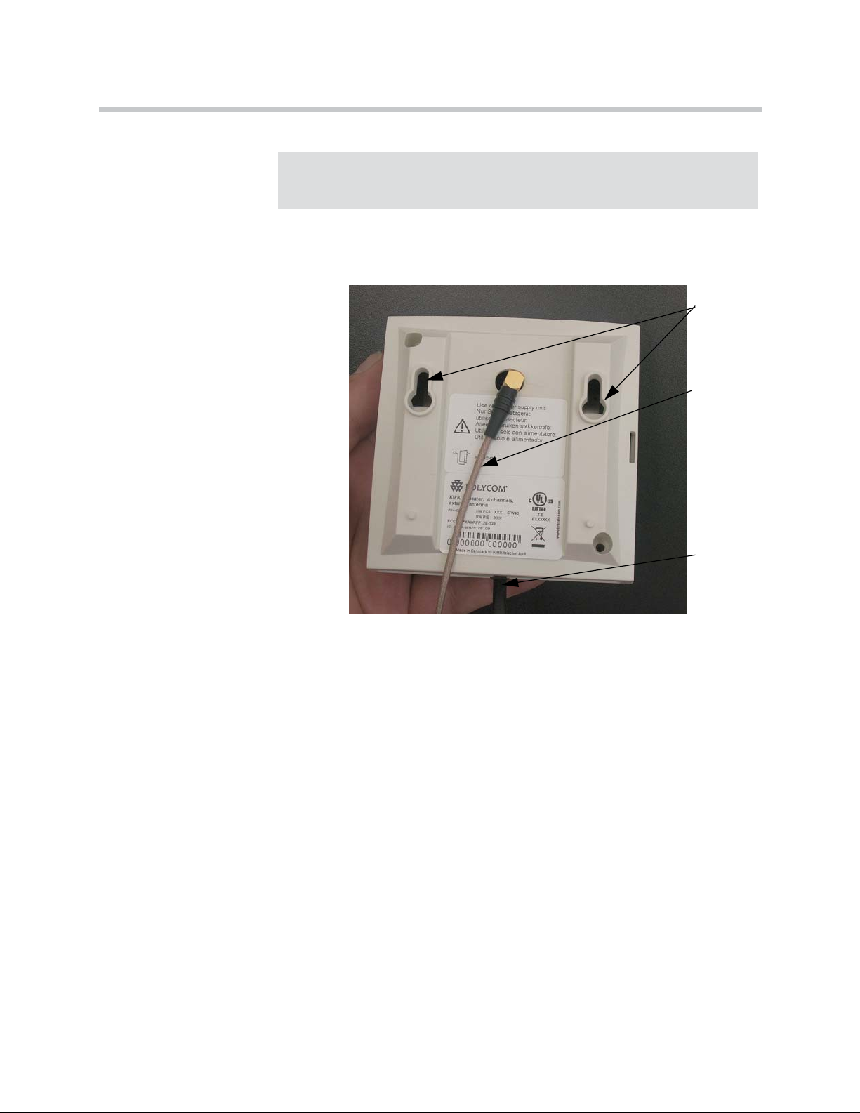
Installing KIRK Repeater
Caution
The repeater must not be installed at any angle other than vertical. If the
repeater is placed upside-down, the coverage area of the repeater is
decreased by 40 - 50% and it might not transmit or receive effectively.
Figure 7-2 Connect Power to the Bottom of the Repeater and External Antenna
Cable to the Rear of the Repeater
1 Connect the power supply cable into the RJ11 connector in the bottom of
the repeater. For repeaters with external antenna, connect the external
antenna cable to the antenna connector in the rear of the repeater as well.
2 Mount the repeater onto the wall using the screws accompanying the
repeater.
7–5
Page 62

KIRK Wireless Server 6000 Installation and Configuration Guide
Figure 7-3 Repeater and External Antenna Installed on the Wall
Only for repeaters supplied
with external antenna
connection)
RepeaterExternal Antenna
Holes for
wall
mounted
screws
External
antenna
cable (only
for repeaters
supplied
with
external
antenna
connection
Note: The external antenna used for the transmitter is to be
fixed-mounted on indoor permanent structures providing a separation
distance of at least 20 cm / 8 inches from all persons during normal
operation and must not be co-located or operating in conjunction with
any other antenna or transmitter. The maximum radiated output power is
1W e.i.r.p. For more information and technical support, please refer to
www.polycom.com.
Recording the Installation Information
After completing the installation of the repeaters, record the location of each
repeater.
Checking Indicators
Verify that the repeater LED indicator is continuously on, indicating that the
repeater is functional.
Power
supply
cable
Powering the KIRK Repeater
Power Options
The power supply for the repeater is 9VDC, 300mA.
7–6
Page 63

Programming a KIRK Repeater with the KIRK Programming Kit
This section provides information about:
• “Content of the KIRK Programming Kit Repeater” on page 7-7
• “Set up of the Hardware for Repeater Programming” on page 7-8
• “Programming the KIRK Repeater with the ServiceTool” on page 7-8
Content of the KIRK Programming Kit Repeater
The Programming Kit Repeater (Part no. 02319508) consists of:
• splitter
• serial cable
Installing KIRK Repeater
Note
For programming the repeater you also need the programming software
(ServiceTool) and the power supply for the repeater. The ServiceTool is
not part of the Programming Kit Repeater but can be downloaded from
www.polycom.com. The power supply for the repeater is to be ordered
separately (Part no. 84642602).
Figure 7-4 Programming Kit Repeater
Splitter
Serial cable
7–7
Page 64

KIRK Wireless Server 6000 Installation and Configuration Guide
Set up of the Hardware for Repeater Programming
1 Unplug the repeater power supply and insert the splitter.
2 Connect the repeater power supply to the splitter and the mains. LED
flashes.
Note: Ensure that you have the appropriate power supply for the local
requirements.
3 Connect the serial cable to the splitter and Com port of your computer.
The repeater is now ready for programming via the ServiceTool.
Note: The above mentioned order of the set up (point 1, 2 and 3) is
important.
Programming the KIRK Repeater with the ServiceTool
The ServiceTool is the tool you access from your desktop and use for repeater
programming, handset adjustment and software download to the handset and
repeater.
The ServiceTool identifies the type of repeater, and with this software it is
possible to program the KIRK Repeater to connect to the KIRK DECT Radio
Infrastructure solutions.
Before you start programming the repeater, ensure that the repeater is
connected to the computer and the mains.
In a single cell solution the numbers assigned to the repeaters must be between
2 and 7. The number of the base station is default set to 1.
In a multi cell solution, the numbering of the base stations and repeaters has to
follow the numbering in the table below.
Table 7-2 Repeater Numbering in a Multi Cell Solution
Base Station Repeater 1 Repeater 2 Repeater 3
0 64 128 192
1 65 129 193
2 66 130 194
3 67 131 195
4 68 132 196
5 69 133 197
6 70 134 198
7 71 135 199
8 72 136 200
9 73 137 201
7–8
Page 65

Table 7-2 Repeater Numbering in a Multi Cell Solution
Base Station Repeater 1 Repeater 2 Repeater 3
10 74 138 202
11 75 139 203
12 76 140 204
13 77 141 205
14 78 142 206
15 79 143 207
16 80 144 208
17 81 145 209
18 82 146 210
19 83 147 211
20 84 148 212
21 85 149 213
22 86 150 214
23 87 151 215
24 88 152 216
25 89 153 217
26 90 154 218
27 91 155 219
28 92 156 220
29 93 157 221
30 94 158 222
31 95 159 223
32 96 160 224
33 97 161 225
34 98 162 226
35 99 163 227
36 100 164 228
37 101 165 229
38 102 166 230
39 103 167 231
40 104 168 232
41 105 169 233
42 106 170 234
43 107 171 235
44 108 172 236
Installing KIRK Repeater
7–9
Page 66

KIRK Wireless Server 6000 Installation and Configuration Guide
Table 7-2 Repeater Numbering in a Multi Cell Solution
Base Station Repeater 1 Repeater 2 Repeater 3
45 109 173 237
46 110 174 238
47 111 175 239
48 112 176 240
49 113 177 241
50 114 178 242
51 115 179 243
52 116 180 244
53 117 181 245
54 118 182 246
55 119 183 247
56 120 184 248
57 121 185 249
58 122 186 250
59 123 187 251
60 124 188 252
61 125 189 253
62 126 190 254
63 127 191 255
64 128 192 0
65 129 193 1
66 130 194 2
67 131 195 3
68 132 196 4
69 133 197 5
70 134 198 6
71 135 199 7
72 136 200 8
73 137 201 9
74 138 202 10
75 139 203 11
76 140 204 12
77 141 205 13
78 142 206 14
79 143 207 15
7–10
Page 67

Table 7-2 Repeater Numbering in a Multi Cell Solution
Base Station Repeater 1 Repeater 2 Repeater 3
80 144 208 16
81 145 209 17
82 146 210 18
83 147 211 19
84 148 212 20
85 149 213 21
86 150 214 22
87 151 215 23
88 152 216 24
89 153 217 25
90 154 218 26
91 155 219 27
92 156 220 28
93 157 221 29
94 158 222 30
95 159 223 31
96 160 224 32
97 161 225 33
98 162 226 34
99 163 227 35
100 164 228 36
101 165 229 37
102 166 230 38
103 167 231 39
104 168 232 40
105 169 233 41
106 170 234 42
107 171 235 43
108 172 236 44
109 173 237 45
110 174 238 46
111 175 239 47
112 176 240 48
113 177 241 49
114 178 242 50
Installing KIRK Repeater
7–11
Page 68

KIRK Wireless Server 6000 Installation and Configuration Guide
Table 7-2 Repeater Numbering in a Multi Cell Solution
Base Station Repeater 1 Repeater 2 Repeater 3
115 179 243 51
116 180 244 52
117 181 245 53
118 182 246 54
119 183 247 55
120 184 248 56
121 185 249 57
122 186 250 58
123 187 251 59
124 188 252 60
125 189 253 61
126 190 254 62
127 191 255 63
128 192 0 64
129 193 1 65
130 194 2 66
131 195 3 67
132 196 4 68
133 197 5 69
134 198 6 70
135 199 7 71
136 200 8 72
137 201 9 73
138 202 10 74
139 203 11 75
140 204 12 76
141 205 13 77
142 206 14 78
143 207 15 79
144 208 16 80
145 209 17 81
146 210 18 82
147 211 19 83
148 212 20 84
149 213 21 85
7–12
Page 69

Table 7-2 Repeater Numbering in a Multi Cell Solution
Base Station Repeater 1 Repeater 2 Repeater 3
150 214 22 86
151 215 23 87
152 216 24 88
153 217 25 89
154 218 26 90
155 219 27 91
156 220 28 92
157 221 29 93
158 222 30 94
159 223 31 95
160 224 32 96
161 225 33 97
162 226 34 98
163 227 35 99
164 228 36 100
165 229 37 101
166 230 38 102
167 231 39 103
168 232 40 104
169 233 41 105
170 234 42 106
171 235 43 107
172 236 44 108
173 237 45 109
174 238 46 110
175 239 47 111
176 240 48 112
177 241 49 113
178 242 50 114
179 243 51 115
180 244 52 116
181 245 53 117
182 246 54 118
183 247 55 119
184 248 56 120
Installing KIRK Repeater
7–13
Page 70

KIRK Wireless Server 6000 Installation and Configuration Guide
Table 7-2 Repeater Numbering in a Multi Cell Solution
Base Station Repeater 1 Repeater 2 Repeater 3
185 249 57 121
186 250 58 122
187 251 59 123
188 252 60 124
189 253 61 125
190 254 62 126
191 255 63 127
192 0 64 128
193 1 65 129
194 2 66 130
195 3 67 131
196 4 68 132
197 5 69 133
198 6 70 134
199 7 71 135
200 8 72 136
201 9 73 137
202 10 74 138
203 11 75 139
204 12 76 140
205 13 77 141
206 14 78 142
207 15 79 143
208 16 80 144
209 17 81 145
210 18 82 146
211 19 83 147
212 20 84 148
213 21 85 149
214 22 86 150
215 23 87 151
216 24 88 152
217 25 89 153
218 26 90 154
219 27 91 155
7–14
Page 71

Table 7-2 Repeater Numbering in a Multi Cell Solution
Base Station Repeater 1 Repeater 2 Repeater 3
220 28 92 156
221 29 93 157
222 30 94 158
223 31 95 159
224 32 96 160
225 33 97 161
226 34 98 162
227 35 99 163
228 36 100 164
229 37 101 165
230 38 102 166
231 39 103 167
232 40 104 168
233 41 105 169
234 42 106 170
235 43 107 171
236 44 108 172
237 45 109 173
238 46 110 174
239 47 111 175
240 48 112 176
241 49 113 177
242 50 114 178
243 51 115 179
244 52 116 180
245 53 117 181
246 54 118 182
247 55 119 183
248 56 120 184
249 57 121 185
250 58 122 186
251 59 123 187
252 60 124 188
253 61 125 189
Installing KIRK Repeater
7–15
Page 72

KIRK Wireless Server 6000 Installation and Configuration Guide
Table 7-2 Repeater Numbering in a Multi Cell Solution
Base Station Repeater 1 Repeater 2 Repeater 3
254 62 126 190
255 63 127 191
Note
Repeater and base station numbers must not be the same. Neither can the
repeater have a number similar to another base station or another repeater
in a situation where common overlap is present between the actual units
(Numbers with red colour show where numbering could be identical
between different units). If this occurs, handover between the different
units is not possible.
Table 7-3 Example of a Normal Base Station/Repeater Configuration
Numbering of base stations and repeaters in a normal configuration
First repeater No. of base station + 64
Base to synchronize on: Number of base station
Second repeater No. of base station + 128
Base to synchronize on: Number of base station
Third repeater No. of base station + 192
Base to synchronize on: Number of base station
Table 7-4 Example of Repeater Jump Configuration
Numbering of repeaters in a repeater jump configuration
First repeater in chain No. of base station + 64
Base to synchronize on: Number of base station
Second repeater in chain No. of base station + 128
Base to synchronize on: Number of previous repeater
Third repeater in chain No. of base station + 192
Base to synchronize on: Number of previous repeater
7–16
For more information about programming the repeater with the ServiceTool,
refer to the Help File in the ServiceTool. The ServiceTool is to be downloaded
from www.polycom.com.
Page 73
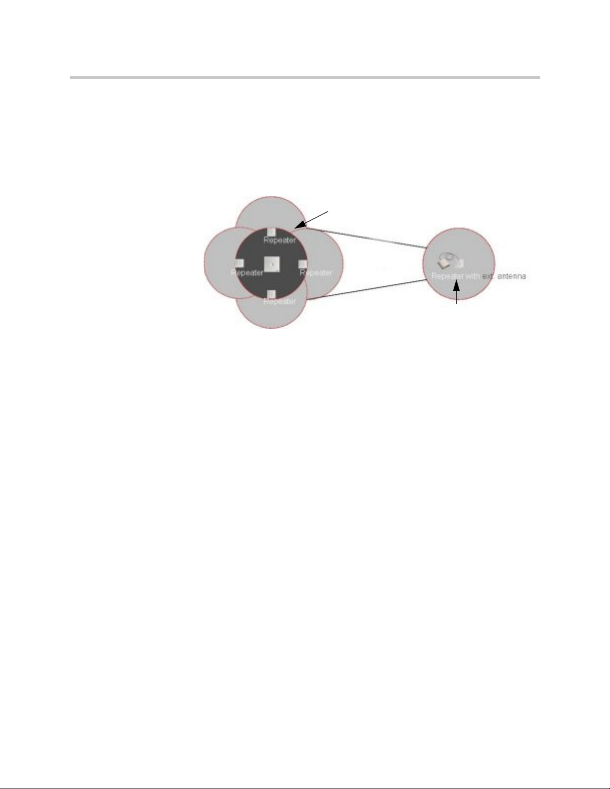
Use of KIRK Repeater With External Antenna
If radio coverage between a base station and a repeater is not needed, it is
possible to synchronize between the radio units using a repeater with external
antenna.
Figure 7-5 Use of Repeaters
Use of KIRK Repeaters
without External Antenna
Installing KIRK Repeater
The distance from the repeaters without external antenna to the base station
must correspond to a RSSI loss of maximum 25dB.
Be aware that inside the area named “radio link” there is no radio coverage,
and therefore a wireless handset cannot be used in this area.
The distance between the base station and the repeater with external antenna
depends on the type of antenna used as well as on the signal attenuation
created by surroundings such as buildings, trees, etc.
Synchronization Ways
The repeater with external antenna, 4 channels, can be programmed to obtain
synchronization on two radio units (base station, wireless server or repeater).
If a situation occurs where the primary sync for some reason breaks down, the
repeater will obtain sync on the alternative sync.
Base Station
Radio Link
Use of KIRK Repeater
Be aware that the primary sync has priority; the alternative sync is only in use
as long as the primary sync is down.
7–17
Page 74

KIRK Wireless Server 6000 Installation and Configuration Guide
7–18
Page 75

Preparing KIRK Handset for Use
This section provides information about how to prepare the handset for use,
to install and charge the battery and how to retrieve the serial numbers on the
different handsets.
This section includes information about:
• “KIRK Handset Description” on page 8-1
• “Installing Battery” on page 8-4
• “Charging KIRK Handsets” on page 8-6
• “Charging KIRK Handsets” on page 8-6
• “Retrieving the Serial Number of the KIRK Handset” on page 8-10
8
Note
Note
For more information on the different handsets, refer to the handset user
guides.
The charger and the power supply for the charger are to be ordered
separately (refer to “KIRK Charger Types and Part Numbers” on page 8-2
and “Power Supply Types and Part Numbers” on page 8-3 for information
on part numbers).
KIRK Handset Description
The handset is a lightweight, ergonomically designed wireless unit that
includes and LCD display and keyboard.
8–1
Page 76

KIRK Wireless Server 6000 Installation and Configuration Guide
KIRK Handset Types and Part Numbers
Table 8-1 Variants of KIRK Handsets
Variants of KIRK Handsets
Handset sets from one of the following categories
(including batteries):
KIRK 4020 Handset
KIRK 4040 Handset
KIRK 4080 Handset
KIRK 5020 Handset
KIRK 5040 Handset
KIRK 6020 Handset
KIRK 6040 Handset
KIRK 7010 Handset
KIRK 7020 Handset
KIRK 7040 Handset
KIRK Charger Types and Part Numbers
Table 8-2 Variants of KIRK Charger
Variants of KIRK Chargers
KIRK Single Charger (For KIRK 4020 and KIRK 4040)
(Part no. 84642462)
KIRK Single Charger (For KIRK 4080)
(Part no. 84642458) (EU, UK)
KIRK Single Charger - Ordinary (For KIRK 5020/5040)
(Part no. 84642472)
8–2
Page 77

Table 8-2 Variants of KIRK Charger
Variants of KIRK Chargers
KIRK Single Charger - USB (For KIRK 5020/5040)
(Part no. 84642472)
kIRK Single Charger - Ordinary (For KIRK 6020/6040)
(Part no. 84642488)
USB cable (Part no. 84642489)
KIRK Single Charger - Ordinary (For KIRK 7010/20/40)
(Part no. 84642493) (countries outside US)
USB cable (Part no. 84642494)
Power Supply Types and Part Numbers
Table 8-3 Variants of Power Supplies
Preparing KIRK Handset for Use
Variants of Power Supplies
Power Supply (For KIRK 4020, 4040 and 4080)
(Part no. 84642602)
Power Supply (For KIRK 5020(/5040)
(Part no. 84642601)
Power Supply (For KIRK 6020/6040/7010/7020/7040)
(Part no. 84642601)
8–3
Page 78

KIRK Wireless Server 6000 Installation and Configuration Guide
Installing Battery
Read the following information before you handle the batteries:
• Do not replace the batteries in potentially explosive environments, such as
rooms where flammable liquids or gases are present.
• The battery will explode if disposed of in a fire.
• Do not charge the batteries unless you use the approved charger and the
proper batteries.
• Only use battery type 84743411 in the 4020 Handset and 4040 Handset. Do
not use these batteries with other products. These batteries were designed
specifically for use with the 4020 Handset and 4040 Handset and the
charger ONLY. Improper use of the batteries may result in fire hazard.
• Only use battery type 84743418 (ICP73048) in the 5020 Handset. Do not
use this battery with other products. This battery was designed
specifically for use with the 5020 Handset and the charger ONLY.
Improper use of the battery may result in fire hazard.
• Only use battery type 84743424 (ICP73048) in the 5020 Handset. Do not
use this battery with other products. This battery was designed
specifically for use with the 5020 Handset and the charger ONLY.
Improper use of the battery may result in fire hazard.
• Do not do anything that would cause the battery to short circuit.
• Do not let the battery or the charger come into contact with conductive
metal objects.
Installing Battery on KIRK 4020/KIRK 4040/KIRK 4080 Handsets
..
Note
Warning
The battery is connected to the handset when it is shipped from the factory.
The battery in a 4080 Handset must not be removed in a potentially
explosive atmosphere. Only use battery type 84743416 in the 4080
Handset.
8–4
Page 79

Preparing KIRK Handset for Use
This section describes how to install the battery on a 4020/4040/4080 Handset.
1 To change the battery unscrew the plate on the rear of the handset to
access the battery compartment. Use a normal screw driver.
2 Insert the screwdriver into the small crack behind the blind cover and
break to open the handset.
Figure 8-1 Remove Back Cover from Handset with Screw Fastener
3 Place the battery plug in the slot in the battery box.
4 Insert battery with the label readable.
5 Replace the back cover.
Installing Battery on KIRK 5020 and KIRK 5040 Handsets
This section describes how to install the battery on a 5020 Handset.
1 To install the battery press down the back cover and slide it towards the
bottom of the handset.
Figure 8-2 Remove Back Cover from Handset
2 Lift off back cover.
8–5
Page 80

KIRK Wireless Server 6000 Installation and Configuration Guide
3 Insert battery with the label readable.
4 Replace the back cover by pressing the back cover back in the locked
position (when you hear a click the back cover is in position).
Charging KIRK Handsets
Using the Charger
Each handset is charged through the use of a handset charger, a compact
desktop unit designed to charge and automatically maintain the correct
battery charge levels and voltage.
The charger for the 4020/4040/4080 Handset is powered by an AC (115VAC
or 230VAC) adapter that supplies the 9VDC at 230mA charger requirement.
The charger for the 5020 Handset is powered by an AC (110VAC to 240VAC)
adapter that supplies the 8VDC at 350mA charger requirement.
Figure 8-3 Single Charger for 4020 Handset and 4040 Handset
8–6
Page 81

Figure 8-4 Single Charger for 4080 Handset
Figure 8-5 Single Charger for 5020 Handset
Preparing KIRK Handset for Use
Figure 8-6 Single Charger for 5040 Handset
8–7
Page 82

KIRK Wireless Server 6000 Installation and Configuration Guide
Charging Battery
KIRK 4020/KIRK 4040 and KIRK 4080 Handsets
When charging the battery for the first time, it is necessary to leave the handset
in the charger for 14 - 16 hours before the battery is fully charged and the
handset ready for use.
Warning
Note
Do not charge 4080 Handset in a potentially explosive atmostphere. Use
only the dedicated charger (orange) for charging of 4080 Handset.
During normal operation, it takes approximately 3 1/2 hours to charge the
handset from fully discharged to its full capacity.
• Place the handset in the charger.
For correct charging, be sure the room temperature is between 0°C and
25°C/32°F and 77°F. Do not place the handset in direct sunlight. The
battery has a built-in heat sensor which will stop charging if the battery
temperature is too high.
If the handset is turned off when placed in charger, only the LED indicates
the charging. When handset is turned off, the LED flashes at a low
frequency while charging and lights constantly when the charging is
finished. There will be no reaction for incoming calls.
If the handset is turned on when charging, the display shows the charging
status. It will not vibrate. B-answer is inactive. The handset reacts
normally for incoming calls. The display goes back to normal mode when
fully charged.
It is necessary to recharge the battery when the display shows BATTERY
LOW, or if the handset cannot be turned on. When the battery is fully
discharged, up to 10 minutes may pass before charging begins (display lights
up). When the charger begins the charging, status is shown on the display if
the handset is turned on.
8–8
The handset displays a progress indicator bar that shows how fully charged
the battery is.
The handset LED gives the following indication:
Page 83

Preparing KIRK Handset for Use
• LED continuously on - handset is fully charged
• LED flashing - handset is charging
KIRK 5020/5040 Handsets
When charging the battery for the first time, it is necessary to leave the handset
in the charger for 14 - 16 hours before the battery is fully charged and the
handset ready for use.
Note
During normal operation, it takes approximately four hours to charge the
handset from fully discharged to its full capacity.
• Place the handset in the charger.
For correct charging, be sure the room temperature is between 0°C and
40°C/32°F and 104°F. Do not place the handset in direct sunlight. The
battery has a built-in heat sensor which will stop charging if the battery
temperature is too high.
If the handset is turned off when placed in charger, nothing indicates the
charging. There will be no reaction for incoming calls.
If the handset is turned on when charging, the display shows a blue
charging icon. The charging icon turns green when fully charged (when
handset is removed from charger, the charging icon disappears). It will not
vibrate. B-answer is inactive. The handset reacts normally for incoming
calls.
It is necessary to recharge the battery when the handset display shows the
battery low icon, or if the handset cannot be turned on.
8–9
Page 84

KIRK Wireless Server 6000 Installation and Configuration Guide
Retrieving the Serial Number of the KIRK Handset
To enable service to the handset, the serial number must be programmed into
the system database via the web based Administration Page of the KWS6000.
(For more information, refer to “Registering KIRK Handsets” on page 13-1).
The serial number (IPEI number) of each handset is found either on a label,
which is placed behind the battery, or on the packaging label.
To show the serial number on the handset display (4020 Handset/4040 and
4080 Handset), press *99984*, and then press ; the serial number appears on
the handset display. Press < for 5 seconds to exit the menu.
To show the serial number on the handset display (5020/5040 Handset), press
Menu, select Status and then select Firmware version. Press exit to exit the
menu.
8–10
Page 85

Preparing KIRK Handset for Use
Retrieving Serial Number on KIRK 4020/KIRK 4040/KIRK 4080 Handsets
This section describes how to retrieve the serial number on a 4020/4040/4080
Handset.
1 Use a screwdriver to unscrew the plate on the rear of the handset to
access the battery compartment.
2 The plate on the rear of the 4080 Handset must not be removed in a
potentially explosive atmostphere.
3 Insert the screwdriver into the small crack behind the blind cover and
press to open the handset.
Figure 8-7 Remove Back Cover from Handset with Screw Fastener
Note
4 Lift the battery and read the serial number.
5 Replace battery and back cover.
To show the serial number on the handset display, press *99984*, and then
press
; the serial number appears on the handset display. Press < for 5
seconds to exit the menu.
8–11
Page 86

KIRK Wireless Server 6000 Installation and Configuration Guide
Retrieving Serial Number on KIRK 5020/5040 Handsets
This section describes how to retrieve the serial number on a 5020 Handset.
1 Press down the back cover and slide it towards the bottom of the handset.
Figure 8-8 Remove Back Cover from Handset
2 Lift off back cover.
3 Lift the battery and read the serial number.
4 Replace battery and back cover.
Note
To show the serial number on the handset display (5020 Handset), press Menu,
select Status and then select Firmware version. Press exit to exit the menu.
8–12
Page 87

Basic Network Configuration
This section provides you with information on basic network configuration.
Basic network settings can be derived from a DHCP server or entered
manually through TCP/IP Setup.
Using DHCP the device requests and obtains an available IP address from a
DHCP server. The device also obtains other parameters such as the default
gateway, subnet mask, DNS server, Time server and other IP parameters from
the DHCP server.
Using manual TCP/IP Setup the IP addresses and other networking
parameters are entered manually through the web based Administration
Page. The static IP addresses are unique, provided and managed by your
system administrator.
9
This section contains information about:
• “Recommended Network Configuration” on page 9-1
• “Assigning DHCP Server Options” on page 9-2
• “Assigning DHCP Server Reservations” on page 9-2
Recommended Network Configuration
When configuring a KWS6000 Solution, it is strongly recommended to
configure:
• KWS6000 using static IP address
• Media resources using DHCP
• Base stations using DHCP
Note
When using DHCP on base stations and media resources, the KWS6000
must have either a static IP address or IP address reservations assigned to
the DHCP server.
9–1
Page 88

KIRK Wireless Server 6000 Installation and Configuration Guide
If the KWS6000 Solution is configured as recommended above, it is possible to
assign options to the DHCP server making it extremely easy to configure all
media resources and base stations. For more information about assigning
options to the DHCP server, refer to “Assigning DHCP Server Options” on
page 9-2.
If the KWS6000 is configured using DHCP, it is necessary to assign a
reservation for the device on the DHCP server. For more information about
assigning reservations to the DHCP server, refer to “Assigning DHCP Server
Reservations” on page 9-2.
Assigning DHCP Server Options
You can provide information about the static IP address of the KWS6000 in the
DHCP server through DHCP options. When defining the IP address of the
KWS6000 in the DHCP server, all media resources and base stations are
configured automatically.
Below you will find a description of how to assign options to a DHCP server
when opening a DHCP server console (MS 2000/2003 DHCP Server):
• When adding a new class you must enter the following information:
— Display name: KIRK IP6000
— Description: KIRK Wireless Server 6000 Solution
— ASCII: KIRK.IP6000 (case sensitive)
• When adding a new option you must enter the following information:
— Name: KWS6000
— Type: String
— Code: 43
• Select options 43.
• Enter the IP address of the KIRK Wireless Server 6000.
Assigning DHCP Server Reservations
If the KWS6000 is configured using DHCP, it is necessary to assign a
reservation for the device on the DHCP server.
9–2
Page 89

10
Configuring KIRK Wireless Server 6000
This section provides you with information on how to power up the KWS6000
and connect the unit to a computer. It also provides information on how to
configure a KWS6000 through the web based Administration Page using
either DHCP or static IP address.
Note
The KWS6000 is pre-configured to use a static IP address.
This section includes information about:
• “Powering up the KWS6000 Server and Media Resource” on page 10-1
• “Connecting a Computer to the KWS6000” on page 10-2
• “Accessing the Web Based Administration Page” on page 10-2
• “Configuring a KIRK Wireless Server 6000 Using Static IP Address” on
page 10-7
• “Configuring a KIRK Wireless Server 6000 Using DHCP” on page 10-13
• “Checking Indicators” on page 10-15
• “Making a Back-Up of the Configuration File” on page 10-15
Powering up the KWS6000 Server and Media Resource
After installing the KWS6000 server you need to power up the unit using:
• Power supply for KWS6000: 8VDC, 1 W maximum when using local
power supply.
Note
The power supply for the KWS6000 is to be ordered separately (Part no.
84642600).
10–1
Page 90

KIRK Wireless Server 6000 Installation and Configuration Guide
Connecting a Computer to the KWS6000
The KWS6000 communicates with the computer through a cross-over patch
cable.
Note
The LAN port of the KWS6000 is a RJ45 connector.
Figure 10-1 Cross-over patch cable (RJ45)
1 Connect the cross-over patch cable to the computer.
2 Connect the cross-over patch cable to the ETH port of the KWS6000.
Accessing the Web Based Administration Page
In order for your computer to communicate with the KWS6000 it is necessary
to change the computer’s Internet Protocol Properties to use the following:
10–2
Page 91

Configuring KIRK Wireless Server 6000
• IP address: 192.168.0.2
• Sub-net mask: 255.255.255.0
How to Change Internet Protocol Properties using Windows XP
1 From the Start menu, point to Connect to and then click Show all
connections.
A Network Connections window appears.
10–3
Page 92

KIRK Wireless Server 6000 Installation and Configuration Guide
2 Under Lan or High-Speed Internet, right-click on Local Area
Connection and click Properties.
A Local Area Connection Properties dialog box appears.
Figure 10-2 Local Area Connection Properties dialog box
3 In the General tab, select Internet Protocol (TCP/IP), and then click
Properties.
An Internet Protocol (TCP/IP) Properties dialog box appears.
Figure 10-3 Internet Protocol Properties dialog box
10–4
Page 93

4 Click Use the following IP address, and then type 192.168.0.2 in the IP
address field.
5 In the Subnet mask field, type 255.255.255.0.
6 Click OK.
You can now reach the KWS6000 using a standard web browser.
How to Access the Administration Page
The web based Administration Page is accessed through a standard web
browser.
1 Open a web browser.
2 In the browsers Address bar, type http://192.168.0.1, and then press
ENTER.
The KWS6000 Administration Page appears.
Figure 10-4 Main page of the Administration Page for wireless server
Configuring KIRK Wireless Server 6000
10–5
Page 94

KIRK Wireless Server 6000 Installation and Configuration Guide
Entering a System User Name and Password
First time you access the Administration Page, you need to log on with user
name and a password.
Note
The default user name of the system is admin and the default password of
the system is ip6000. It is strongly recommeded to change the password,
refer to “Changing System User Name and Password” on page 15-2.
Figure 10-5 Adm. Page: Enter Network Password dialog box
1 In the User Name field, type admin.
2 In the Password field, type ip6000.
3 Click OK.
10–6
Page 95

Configuring KIRK Wireless Server 6000
Configuring a KIRK Wireless Server 6000 Using Static IP Address
This section describes how to configure a KWS6000 using static IP address.
Note
The KWS6000 is pre-configured to use a static IP address. It is strongly
recommended to configure the KWS6000 using static IP address.
Figure 10-6 KWS6000 installation
For information on accessing the web based Administration Page, refer to
“Accessing the Web Based Administration Page” on page 10-2.
This section contains information about:
• “General Configuration” on page 10-8
• “Wireless Server Configuration” on page 10-9
• “Built-In Media Resource Configuration” on page 10-9
• “SIP Configuration” on page 10-10
• “Security Configuration” on page 10-12
10–7
Page 96

KIRK Wireless Server 6000 Installation and Configuration Guide
General Configuration
On the Configuration/General page you define IP, DNS and NTP settings for
the KWS6000.
1 Click Configuration, and then click General.
Figure 10-7 Adm. Page WS: Configuration/General page
2 Click Use Static IP Address.
3 In the IP Addr field, type the IP address of the KWS6000.
4 In the Netmask field, type a new network mask (optional).
Contact your system administrator for more information.
5 In the Gateway field, type the IP address of the default gateway
(optional).
The default gateway serves as an access point to another network.
Contact your system administrator for more information.
6 In the MTU field (Maximum Translation Unit), type the size of the largest
packet, that your network protocol can transmit (optional).
7 In the Domain field, type the domain name of the system (optional).
8 In the Server field (under DNS - Domain Name System), type the IP
address of the DNS server (optional).
9 In the Server field (under NTP - Network Time Protocol), type the IP
address of the NTP server from which the system will obtain the current
time (optional).
10 From the Time Zone list, select the wanted time zone (optional).
11 Click Save to save your general configuration data.
10–8
Page 97

Wireless Server Configuration
On the Configuration/Wireless Server page you configure the KWS6000 to
allow subscription. If the system does not allow subscription, it is not possible
to subscribe a handset.
1 Click Configuration, and then click Wireless Server.
2 Select the Subscription Allowed check box (optional).
Note: If not selected, you cannot subscribe a handset.
3 Click Save.
Built-In Media Resource Configuration
On the Configuration/Media Resource page you configure the built-in Media
Resource.
Configuring KIRK Wireless Server 6000
1 Click Configuration, and then click Media Resource.
Figure 10-8 Adm. Page WS: Configuration/Media Resource page
2 In the Host field, type localhost if you want to activate the built-in media
resource.
3 Click Save.
10–9
Page 98

KIRK Wireless Server 6000 Installation and Configuration Guide
SIP Configuration
On the Configuration/SIP page you define general SIP settings, information
about authentication, DTMF signalling, message waiting indication and
media.
1 Click Configuration, and then click SIP.
Figure 10-9 Adm. Page WS: Configuration/SIP page
10–10
2 In the Local Port field, type the local port number.
The default local port number is 5060.
Note: The local port is the port on which the KWS6000 listens for
incoming SIP-signalling.
3 In the Default Domain field, type the name of the domain.
Note: If no user specific domain is configured, the handsets registered on
the KWS6000 will use the default domain as the domain part of the SIP
URI; e.g. John Doe <sip:1234@somecompany.com>.
4 In the Proxy field, type a SIP proxy (optional).
Note: The proxy is the SIP URI of the SIP-proxy. The KWS6000 will route
all outgoing SIP signalling to the proxy, e.g. SIP registrations and
outgoing calls.
Page 99

Configuring KIRK Wireless Server 6000
5 In the Registation Expire(sec) field, type the number of seconds before a
SIP registration will be renewed.
The default value is 3600.
6 In the Max Forwards field, type a value (optional).
The default value is 70.
7 From the SIP Type of Service list, select between Nothing, Low delay,
Reliability, Throughput and Minimum cost.
The default setting is Nothing.
8 In the Default User field, type the user name.
9 In the Default Password field, type the password (optional).
Note: If no handset specific authentication user name/password is
configured, handsets registered on the KWS6000 will use the default user
name/password for authentication.
10 Select the Send as RTP check box (Real-time Transport Protocol), if you
want the keypad signalling sent as RTP packets with DTMF code
(optional).
11 Select the Send as SIP Info check box, if you want the keypad signalling
sent as SIP INFO (optional).
12 In the Tone Duration(msec) field, type the time length of the tone in
miliseconds.
The default value is 270.
13 Select the Enable Indication check box, if you want to handle MWI
message (optional).
14 Select the Enable Subscription check box, if you want to subscribe to
MWI indications from the SIP proxy (optional).
15 In the Subscription Expire(sec) field, type a value.
The default value is 3600.
16 From the Packet Duration(msec) list, select between 10, 20 and 40.
17 From the Media Type of Service list, select between Nothing, Low delay,
Reliability, Throughput and Minimum cost.
The default setting is Nothing.
18 In the
Port Range Start field, type a value.
The default value is 58000.
19 In the Codec priority fields, define the priorities of codecs.
20 Click Save to save your SIP configuration data.
10–11
Page 100

KIRK Wireless Server 6000 Installation and Configuration Guide
Security Configuration
It is possible to change the password for the unit from the
Configuration/Security page.
1 Click Configuration, and then click Security (optional).
Figure 10-10Adm. Page: Configuration/Security page
2 In the Current password field, type the current password.
3 In the New username field, type a new username.
4 In the New password field, type a password.
5 In the New password again, type the password again.
6 Click Allow remote logging if it should be possible to perform remote
logging (Useful in case of problem solving).
7 Click Save.
10–12
 Loading...