

Page 1

Version 1.0 | September 2010 | 14205700-Hd.1.0
Polycom® KIRK
®
Wireless Server 2500
Installation Guide
Page 2

ii Polycom, Inc.
Copyright © Polycom, Inc.
All Rights Reserved
Proprietary and Confidential
The information contained herein is the sole intellectual property of Polycom, Inc. No distribution,
reproduction or unauthorized use of these materials is permitted without the expressed written consent
of Polycom, Inc. Information contained herein is subject to change without notice and does not represent
commitment of any type on the part of Polycom, Inc. Polycom and Accord are registered trademarks of
Polycom, Inc.
Notice
While reasonable effort was made to ensure that the information in this document was complete and
accurate at the time of printing, Polycom, Inc., cannot assume responsibility for any errors. Changes
and/or corrections to the information contained in this document may be incorporated into future issues.
Page 3

Polycom, Inc. 1
Contents
Contents
1 KWS2500 Installation . . . . . . . . . . . . . . . . . . . . . . . . . . . . . 3
Installing the KWS2500 . . . . . . . . . . . . . . . . . . . . . . . . . . . . . . . . . . . . . . . . . . . . . 3
Specifications . . . . . . . . . . . . . . . . . . . . . . . . . . . . . . . . . . . . . . . . . . . . . . . . . . 3
KWS 2500 Components . . . . . . . . . . . . . . . . . . . . . . . . . . . . . . . . . . . . . . . . . 4
Connections . . . . . . . . . . . . . . . . . . . . . . . . . . . . . . . . . . . . . . . . . . . . . . . . . . . 6
General Installation Information . . . . . . . . . . . . . . . . . . . . . . . . . . . . . . . . . . 8
Installing the KWS 2500 on a Flat Surface . . . . . . . . . . . . . . . . . . . . . . . . . . 8
Installing the KWS2500 on a Wall . . . . . . . . . . . . . . . . . . . . . . . . . . . . . . . . . 8
Connecting the KWS2500 Cables . . . . . . . . . . . . . . . . . . . . . . . . . . . . . . . . . 9
Installing Interface Cards and CPU Cards . . . . . . . . . . . . . . . . . . . . . . . . . 10
2 Replacing Components . . . . . . . . . . . . . . . . . . . . . . . . . . . 15
Component Replacement . . . . . . . . . . . . . . . . . . . . . . . . . . . . . . . . . . . . . . . . . . 15
Component Replacement Precautions . . . . . . . . . . . . . . . . . . . . . . . . . . . . 15
3 Regulatory Notices . . . . . . . . . . . . . . . . . . . . . . . . . . . . . . 17
International Regulatory and Product Information . . . . . . . . . . . . . . . . . . . . 17
Important Safety Instructions and Product Information . . . . . . . . . . . . . . . . 20
A RJ45 Wiring . . . . . . . . . . . . . . . . . . . . . . . . . . . . . . . . . . . 29
B Cable Connections . . . . . . . . . . . . . . . . . . . . . . . . . . . . . . 31
Analogue Interface Card . . . . . . . . . . . . . . . . . . . . . . . . . . . . . . . . . . . . . . . 31
Base Station Interface Card . . . . . . . . . . . . . . . . . . . . . . . . . . . . . . . . . . . . . 31
RJ45 Pins . . . . . . . . . . . . . . . . . . . . . . . . . . . . . . . . . . . . . . . . . . . . . . . . . . . . . 32
Tables . . . . . . . . . . . . . . . . . . . . . . . . . . . . . . . . . . . . . . . 33
Figures . . . . . . . . . . . . . . . . . . . . . . . . . . . . . . . . . . . . . . 35
Index . . . . . . . . . . . . . . . . . . . . . . . . . . . . . . . . . . . . . . . . 37
Page 4

Polycom Kirk Wireless Server 2500 Installation Guide
2 Polycom, Inc.
Page 5

Polycom, Inc. 3
1
KWS2500 Installation
This guide describes how you install the KIRK Wireless Server 2500.
Installing the KWS2500
The KWS2500 can be installed on a flat surface or on a wall. Before you start the
installation, place the KWS2500 on a stable flat surface in the selected location,
and inspect the package for any damage and report it to the reseller or
distributor immediately.
Specifications
Important Please review all the safety instructions for important safety and
regulatory information
Table 1-1 Physical Dimensions
Physical dimensions
Height 177mm
Width 194 mm
Depth 328 mm
Weight 1.16 kg (excl. power supply)
Table 1-2 Power Supply
Power supply
AC Input 100-240 VAC, 50/60 Hz
Page 6
Polycom KIRK Wireless Server 2500 Installation Guide Installing the KWS2500
4 Polycom, Inc.
KWS2500 Components
The following table contains all KWS2500 parts and their part numbers.
Table 1-3 Power Consumption
Power consumption
Typical AC Power Consumption 45 Watt
Max. AC Power Consumption Max 60 Watt
Table 1-4 Environment
Environment
Operating temperature 0°C - 40°C (22° - 104°F)
Storage temperature -30°C - 70°C (40° - 158°F)
Relative humidity 20% - 80% Non condensing
Operating altitude Up to 2000 m (6,500 ft)
Operating ESD level 4 KV
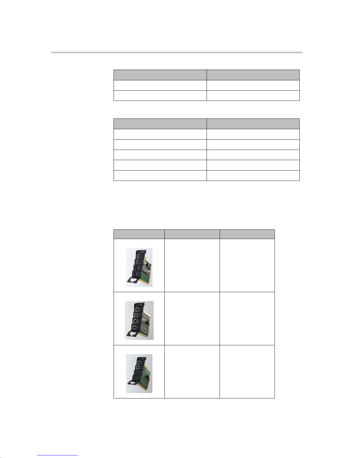
Table 1-5 KWS2500 Components
Picture Description Part Numbers
Base Station Interface
card (8 base stations)
0233 9100
Analogue Interface
card (16 lines)
0233 9200
Analogue Interface
card (8 lines)
0233 9220
Page 7
Polycom, Inc. 5
Installing the KWS2500 KWS2500 Installation
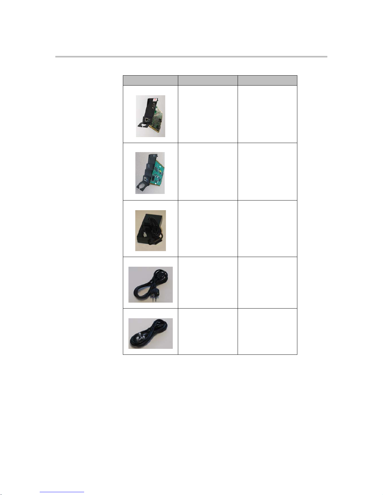
CPU card 0233 9600
Media Resource Card 0233 9700
Mains adaptor 8476 9904 - AV only
EU mains cable 8468 7013
UK mains cable 8468 7014
Table 1-5 KWS2500 Components
Picture Description Part Numbers
Page 8
Polycom KIRK Wireless Server 2500 Installation Guide Installing the KWS2500
6 Polycom, Inc.
Connections
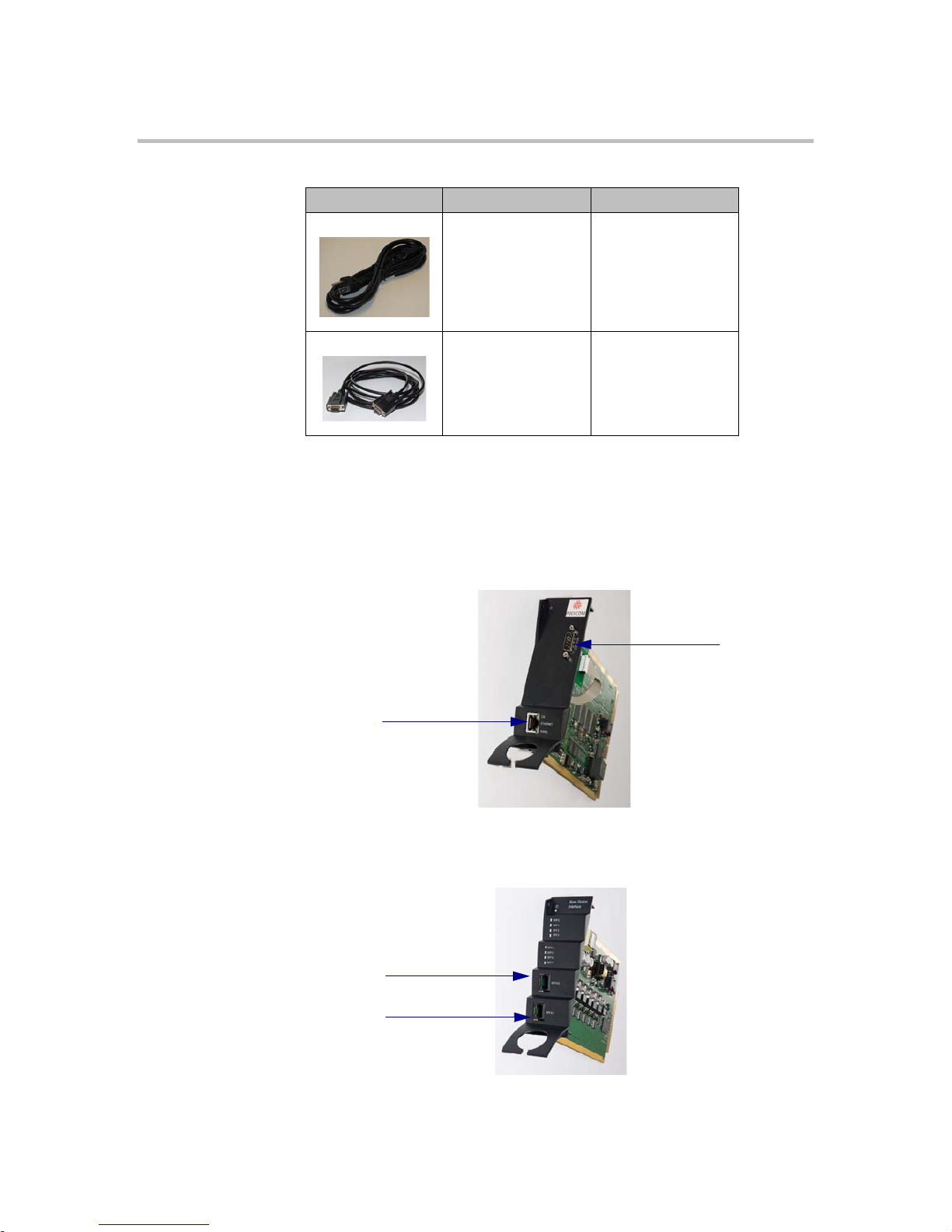
Figure 1-1 CPU Card Connections
Figure 1-2 RJ45 Connections for Base Stations
US mains cable 8468 7015
RS232 cable 13281100
Table 1-5 KWS2500 Components
Picture Description Part Numbers
Ethernet
RS232
A: RJ45 Connection
B: RJ45 Connection
Page 9
Polycom, Inc. 7
Installing the KWS2500 KWS2500 Installation
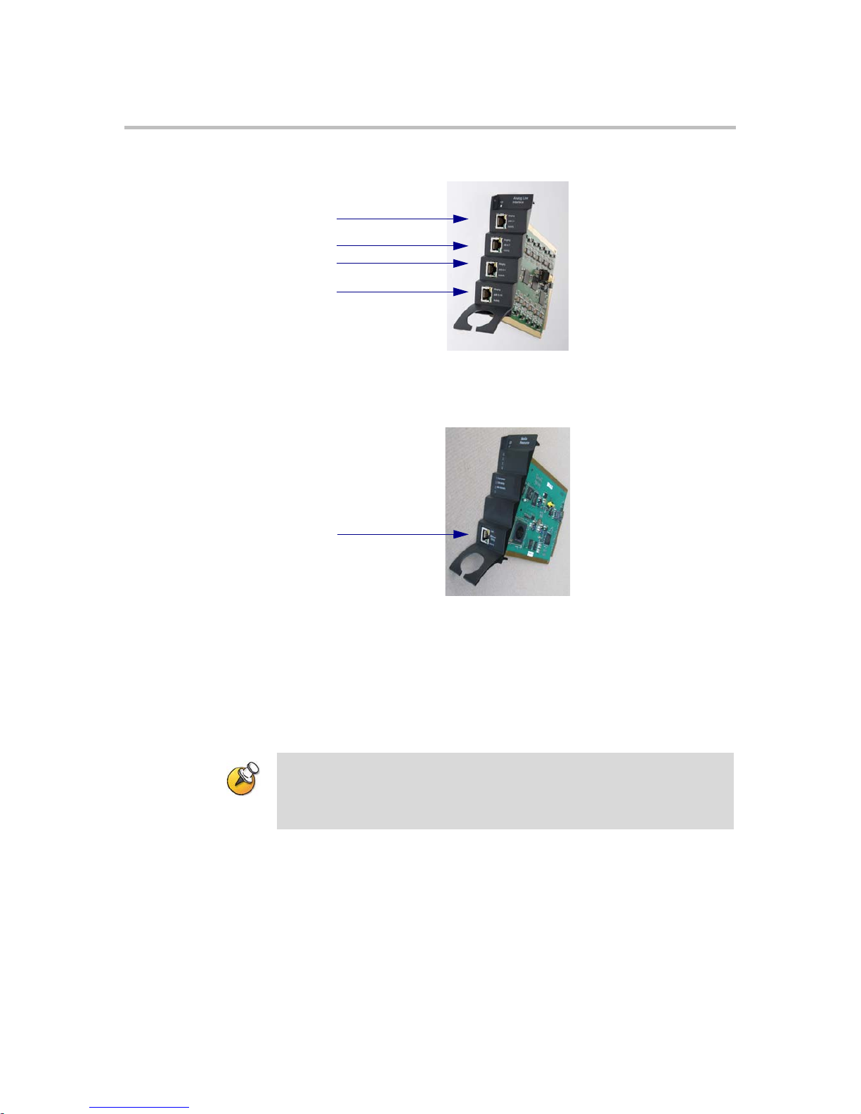
Figure 1-3 RJ45 Connections for AB Lines
Figure 1-4 Media Resource Card Connection
General Installation Information
General Mounting Safety Precautions
• Keep the area around the KWS2500 clean and free of clutter.
• Decide on a suitable surface that will hold the KWS2500 unit. It should be
situated in a clean, dry, and dust-free area that is well ventilated. Avoid
areas where heat, electrical noise, and electromagnetic fields are generated.
• Place it near an earthed power outlet.
A RJ45 Connection
B RJ45 Connection
D RJ45 Connection
C RJ45 Connection
A Ethernet
Important Electrical shock hazards from the telecommunication network
and AC mains are possible with this equipment. To minimize risk to service
personnel and users, the system must be connected to an outlet with a
third-wire earth connection.
Page 10

Polycom KIRK Wireless Server 2500 Installation Guide Installing the KWS2500
8 Polycom, Inc.
Installing the KWS2500 on a Flat Surface
Before you start installation, take notice of the following safety precautions.
Flat Surface Mounting Safety Precautions
• Ensure the surface can support the weight of the unit.
• Never install the KWS2500 on the floor.
• Never place anything on top of the KWS2500. The top plate must be free to
allow sufficient cooling.
To Install the KWS2500 on a Flat Surface
1 Remove the KWS2500 from its package.
2 Before placing the unit, carefully turn it upside down and mount the four
rubber pads supplied in the package. One must be placed at each corner of
the bottom plate.
3 Place it on a clean, flat, horizontal surface.
Installing the KWS2500 on a Wall
Before you start installation, take notice of the following safety precautions.
Wall Mounting Safety Precautions
• Ensure the wall quality is good enough for holding the unit. Avoid
high-porous surfaces, joints and similar.
• Never use countersunk screws.
• Leave at least 10 centimeter of free air above the unit for ventilation.
Connecting the KWS2500 Cables
When the KWS2500 has been mounted, the cables can be connected.
Cable Safety Precautions
Before you connect the cables, ensure to take the following electrical safety
precautions.
• Always use an earthed socket for power.
• Use a power cord with protective earth (PE) connection suitable for the
country where it is being used and with the appropriate local approvals.
• Power supply cables must be connected prior to connecting any interface
cables.
Page 11

Polycom, Inc. 9
Installing the KWS2500 KWS2500 Installation
• The interface cables must be removed before any interface card is removed
or replaced.
• When unplugging power, unplug AC mains power first before unplugging
the power connector from the KWS2500.
• The AC adapters must never be hanging by their own weight in the AC
mains connector or the output connector.
To Connect Power Cable
The KWS2500 has one power plug on the back panel.
1 Plug a suitable power cord into the AC power adapter.
2 Insert the AC power adapter output connector firmly into the socket on
the KWS2500 so that the retention clip snaps to the plug.
3 Plug the AC power adapter into mains.
4 When powering down the unit, the power connector must be unplugged
to ensure the unit is completely powered off.
Installing Interface Cards and CPU Cards
Before you install an interface or a CPU card ensure to take the following
precautions.
Safety Precautions
Cards contain static sensitive circuitry and may be destroyed or damaged by
electrostatic discharge (ESD).
• Make sure you re using proper ESD equipment to prevent damage to the
system.
• Fill all empty slots with blanking front plates to close the front.
To Install Interface Cards
1 With two hands, gently slide the interface card into the unit. Give it a
gentle push on the last centimeter so that it enters the backplane connector
properly.
Avoid pushing on the front connectors - push only on the plastic parts at
the top and bottom.
Page 12

Polycom KIRK Wireless Server 2500 Installation Guide Installing the KWS2500
10 Polycom, Inc.
Figure 1-5 Installing Interface Cards
2 Plug the interface cables into the card as described in “Connecting
Interface Cables” on page 11.
To Install C P U C a rds
1 Ensure that the KWS2500 is powered off completely.
2 With two hands, gently slide the card into the unit. Give the card a gentle
push on the last centimeter so that it enters the backplane connector
properly.
Avoid pushing on the front connectors - push only on the plastic parts at
the top and bottom.
Page 13

Polycom, Inc. 11
Installing the KWS2500 KWS2500 Installation
Figure 1-6 Installing CPU card
3 Plug the interface cables into the card as described in “Connecting
Interface Cables” on page 11.
4 Connect the KWS2500 to a PC using theRS232 cable.
5 Connect the power and reboot the unit.
Connecting Interface Cables
The front interface of the KWS2500 is provided with connectors for the different
interfaces provided. Please see the KWS2500 User Guide for the actual pin-out
of the different connectors.
The cables can be harnessed in two ways as shown in the following figures
depending on the installation requirements.
Page 14

Polycom KIRK Wireless Server 2500 Installation Guide Installing the KWS2500
12 Polycom, Inc.
Figure 1-7 Harnessing cables to the back and out
Page 15

Polycom, Inc. 13
Installing the KWS2500 KWS2500 Installation
Figure 1-8 Harnessing cables to the side and out.
Regardless of which way is used for harnessing, you must guide the cables
through the opening in the plastic front. This ensures safe retention of the cable.
Page 16

Polycom KIRK Wireless Server 2500 Installation Guide Installing the KWS2500
14 Polycom, Inc.
Page 17

Polycom, Inc. 15
2
Replacing Components
The KWS2500 is designed to minimize down-time. Several components can be
replaced while the system is up.
Component Replacement
The following components are hot-swappable:
• Interface cards
• AC adapters
The following require a power down of the system:
• Backplane
• CPU card
Before replacing any components, take notice of the component replacement
precautions.
Component Replacement Precautions
• Cards contain static sensitive circuitry and may be destroyed or damaged
by electrostatic discharge (ESD.)
• All maintenance tasks must be performed by qualified, authorized
personnel only.
• Use only original replacement parts.
• Make sure you are using proper ESD equipment, to prevent damage to the
system.
• Fill all empty slots with blanking front plates to close the front.
Page 18

Polycom KIRK Wireless Server Installation Guide Component Replacement
16 Polycom, Inc.
Replacing Interface and CPU cards
To Replace a New Hot-swappable Card
1 Ensure the KWS2500 unit is properly earthed.
2 Unplug all interface cables on the card that needs to be replaced, noticing
which goes where.
3 Remove the cables from the opening in the plastic front.
4 With two hands, gently pull out the card.
5 Gently slide the new card into the unit. Give it gentle push on the last
centimeter so that it enters the backplane connector properly. Avoid
pushing on the front connectors, push only on the plastic parts at the top
and bottom.
6 Plug the interface cables into the card.
To Replace or Install a New CPU Card
1 Power off the KWS2500 completely.
2 Ensure the KWS2500 unit is properly earthed.
3 Unplug all interface cables on the card.
4 Remove the cables from the opening in the plastic front.
5 With two hands, gently pull out the card.
6 Gently slide the new card into the unit. Give it gentle push on the last
centimeter so that it enters the backplane connector properly. Avoid
pushing on the front connectors, push only on the plastic parts at the top
and bottom.
7 Plug the interface cables into the card.
8 Connect power and reboot the unit.
Replacing the Backplane
The backplane cannot be replaced on-site. The KWS2500 will have to be
returned for repair or be replaced with a new one. If a new KWS2500 is to be
installed, you can move the cards from the faulty KWS2500 to the new one.
T
Page 19

Polycom, Inc. 17
3
Regulatory Notices
This section contains important safety regulations for the KWS2500.
International Regulatory and Product Information
United States Federal Communication
Commission (FCC)
Part 15: Class A Statement. This equipment has
been tested and found to comply with the limits for a
Class A digital device, pursuant to Part 15 of the FCC
Rules. Test limits are designed to provide reasonable
protection against harmful interference when the
equipment is operated in a commercial environment.
This equipment generates, uses and can radiate
radio-frequency energy and, if not installed and used
in accordance with the instruction manuals, may
cause harmful interference to radio communications.
Operation of this equipment in a residential area is
likely to cause harmful interference, in which case the
user will be required to correct the interference at his
or her own expense.
Part 68: Network Registration Number. This
equipment is registered with the FCC in accordance
with Part 68 of the FCC Rules. This equipment is
identified by the FCC registration number.
If requested, the FCC registration Number and REN
must be provided to the telephone company.
Any repairs to this equipment must be carried out by
Polycom Inc. or our designated agent. This
Page 20

Polycom KIRK Wireless Server 2500 Installation Guide International Regulatory and Product Information
18 Polycom, Inc.
stipulation is required by the FCC and applies during
and after the warranty period.
United States Safety Construction Details:
o All connections are indoor only.
o No direct connections to public networks.
o Unit is intended for RESTRICTED ACCESS
LOCATION.
o Unit is to be installed in accordance with the
National Electrical Code.
o The branch circuit overcurrent protection shall
be rated 20 A for the AC system.
o This equipment has a maximum operating
ambient of 40°C,
CE Mark R&TTE Directive
Polycom Inc., declares that the Polycom KWS 2500 is
in conformity with the following relevant harmonized
standards:
EN 60950-1:2006
EN 55022:2006
EN 55024:1998, A1:2002, A2:2003
Following the provisions of the Council Directive
1999/CE on radio and telecommunication terminal
equipment and the recognition of its conformity.
This KIRK product has been marked with
the CE mark. This mark indicates
compliance with EEC Directives 89/336/EEC,
73/23/EEC 1999/5/EC. A full copy of the
Declaration of Conformity can be obtained
from Polycom Ltd, 270 Bath Road, Slough,
Berkshire, SL1 4DX, UK.
The WEEE Marking on this equipment
indicates that the product must not be
disposed of with unsorted waste, but must
be collected separately.
Page 21

Polycom, Inc. 19
International Regulatory and Product Information Regulatory Notices
Canadian Department of Communications
This Class [A] digital apparatus complies with
Canadian ICES-003.
Notice: The Industry Canada label identifies certified
equipment. This certification means that the
equipment meets telecommunication network
protective, operational and safety requirements as
prescribed in the appropriate Terminal Equipment
Technical Requirements document(s). The
Department does not guarantee the equipment will
operate to the user's satisfaction.
Before installing this equipment, users should ensure
that it is permissible to be connected to the facilities
of the local telecommunications company. The
equipment must also be installed using an acceptable
method of connection. The customer should be
aware that compliance with the above conditions may
not prevent degradation of service in some situations.
Repairs to certified equipment malfunctions, may give
the telecommunications company causes to request
the user to disconnect the equipment.
Users should ensure for their own protection that the
electrical ground connections of the power utility,
telephone lines and internal metallic water pipe
system, if present, are connected together. This
precaution may be particularly important in rural
areas.
Caution: Users should not attempt to make such
connections themselves, but should contact the
appropriate electric inspection authority, or
electrician, as appropriate.
Page 22

Polycom KIRK Wireless Server 2500 Installation Guide Important Safety Instructions and Product Information
20 Polycom, Inc.
Important Safety Instructions and Product Information
Before using your telephone equipment, you should always follow basic safety
instruction to reduce the risk of fire, electrical shock and injury to persons, and
damage to property.
1 Read and understand all instructions
2 Follow all warnings and instructions including those marked on the
product
3 Unplug this product before cleaning. Do not use liquid cleaners or aerosol
cleaners. Use damp cloth for cleaning
4 Do not install the telephone equipment in the bathroom or near a wash
bowl, kitchen sink, or laundry tub, in a wet basement, or near a swimming
pool
5 The product should be operated only from the type of power source
indicated on the instructions. If you are not sure of the type of power
supply, consult your dealer or local power company.
6 Do not overload wall outlets and extension cords as this can result in fire
or electrical shock.
7 Never push objects of any kind into this product through cabinet slots as
they may touch dangerous voltage points or short out parts that could
result in fire, electrical shock, or injury. Never spill liquid of any kind into
this product.
8 To reduce the risk of electrical shock or burns, do not disassemble this
product. Opening or removing covers may expose you to dangerous
voltages, dangerous electrical current, or other risks. Incorrect reassemble
can cause electrical shock when the appliance is subsequently used. If the
product need repair, consult your dealer.
9 This product does not support connections to outside plant.
10 Refer servicing to qualified service personnel under the following
conditions:
If liquid has been spilled into the product
If the product has been exposed to rain or water
If the product does not operate normally when following the operating
instructions in the manual. Adjust only those controls that are covered
by the operation instructions. Improper adjustment of other controls
may result in damage and will often require extensive work by qualified
service personnel to restore the product to normal operation.
If the product has been dropped or cabinet has been damaged
If the product exhibits a distinct change in performance
Page 23

Polycom, Inc. 21
Important Safety Instructions and Product Information Regulatory Notices
Warning
1 Avoid using telephone during an electrical storm. There may be a risk of
electrical shock from lightning
2 Do not use the telephone to report a gas leak in the vicinity of the leak
3 Do not place the unit near microwave ovens, radio equipment, or
non-ground connected televisions. These appliances may cause electrical
interference to the base or handset
4 Installation must be performed in accordance with all relevant national
wiring rules
5 Plug acts as Disconnect Device - The socket outlet to which this apparatus
is connected must be installed near the equipment and must always be
readily accessible
6 The system will not operate in the event of a blackout. Please keep a
backup phone for emergencies
Intrinsic safety
Do not install the unit in conditions where there is a danger of electrically
ignited explosions.
Exposure to sunlight, heat and moisture
Do not expose the unit to direct sunlight for long periods. Keep away from
excessive heat and moisture.
Spare parts and accessories
Use only approved spare parts and accessories. The operation of non-approved
parts cannot be guaranteed and may even cause damage.
RF compliance information
The users manual or instruction manual for an intentional or unintentional
radiator shall caution the user that changes or modifications not expressly
approved by the party responsible for compliance could void the user’s
authority to operate the equipment.
NOTICES
FCC Note: This device complies with Part 15 of the FCC rules. Operation is
subject to the following two conditions: (1) This device may not cause harmful
interference, and (2) this device must accept any interference received,
including interference that may cause undesired operation.
Page 24

Polycom KIRK Wireless Server 2500 Installation Guide Important Safety Instructions and Product Information
22 Polycom, Inc.
IC Note: Operation is subject to the following two conditions: (1) This device
may not cause interference, and (2) this device must accept any interference,
including interference that may cause undesired operation of the device. The
term “IC:” before the certification /registration number only signifies that the
Industry Canada technical specifications were met.
Privacy of communications may not be ensured when using this telephone.
Information to user: The users manual or instruction manual for an intentional
or unintentional radiator shall caution the user that changes or modifications
not expressly approved by the party responsible for compliance could void the
user’s authority to operate the equipment.
Polycom® Product Warranty Statement
The software included in this Product (including, without limitation, firmware
and all updated thereto, including any software that may be downloaded
electronically via the internet or otherwise (the “Software”) is licensed, not
sold. Customer shall not reverse compile, disassemble or otherwise reverse
engineer, embed within any other software product, or modify in any manner
with respect thereto, the Software in whole or in part.
THE TERMS AND CONDITIONS APPLICABLE TO POLYCOM’S
LIMITED WARRANTY ARE AS SET FORTH BELOW (AND ARE ALSO
INCLUDED IN THE DOCUMENTATION PACKAGED WITH NEW
POLYCOM PRODUCTS):
LIMITED WARRANTY. Polycom warrants to the end user (“Customer”) that
the product will be free from defects in workmanship and materials, under
normal use and service, for one year, or such longer period as Polycom may
announce publicly from time to time for particular products, from the date of
purchase from Polycom or its authorized reseller. Polycom’s sole obligation
under this express warranty shall be, at Polycom’s option and expense, to
repair the defective product or part, deliver to Customer an equivalent product
or part to replace the defective item, or if neither of the two foregoing options
is reasonably available, Polycom may, in its sole discretion, refund to Customer
the purchase price paid for the defective product. All products that are replaced
will become the property of Polycom. Replacement products or parts may be
new or reconditioned. Polycom warrants any replaced or repaired product or
part for ninety (90) days from shipment, or the remainder of the initial warranty
period, whichever is longer. Products returned to Polycom must be sent
prepaid and packaged appropriately for safe shipment, and it is recommended
that they be insured or sent by a method that provides for tracking of the
package. Responsibility for loss or damage does not transfer to Polycom until
the returned item is received by Polycom. The repaired or replaced item will be
shipped to Customer, at Polycom's expense, not later than thirty (30) days after
Polycom receives the defective product, and Polycom will retain risk of loss or
damage until the item is delivered to Customer.
EXCLUSIONS. Polycom will not be liable under this limited warranty if its
testing and examination disclose that the alleged defect or malfunction in the
product does not exist or results from:
• Failure to follow Polycom's installation, operation, or maintenance
instructions.
Page 25

Polycom, Inc. 23
Important Safety Instructions and Product Information Regulatory Notices
• Unauthorized product modification or alteration.
• Unauthorized use of common carrier communication services accessed
through the product.
• Abuse, misuse, negligent acts or omissions of Customer and persons under
Customer's control; or
• Acts of third parties, acts of God, accident, fire, lighting, power surges or
outages, or other hazards.
WARRANTY EXCLUSIVE. IF A POLYCOM PRODUCT DOES NOT
OPERATE AS WARRANTED ABOVE, CUSTOMER'S SOLE REMEDY FOR
BREACH OF THAT WARRANTY SHALL BE REPAIR, REPLACEMENT, OR
REFUND OF THE PURCHASE PRICE PAID, AT POLYCOM'S OPTION. TO
THE FULL EXTENT ALLOWED BY LAW, THE FOREGOING WARRANTIES
AND REMEDIES ARE EXCLUSIVE AND ARE IN LIEU OF ALL OTHER
WARRANTIES, TERMS, OR CONDITIONS,
EXPRESS OR IMPLIED, EITHER IN FACT OR BY OPERATION OF LAW,
STATUTORY OR OTHERWISE, INCLUDING WARRANTIES, TERMS, OR
CONDITIONS OF MERCHANTABILITY, FITNESS FOR A PARTICULAR
PURPOSE, SATISFACTORY QUALITY, CORRESPONDENCE WITH
DESCRIPTION, AND NON-INFRINGEMENT, ALL OF WHICH ARE
EXPRESSLY DISCLAIMED. POLYCOM NEITHER ASSUMES NOR
AUTHORIZES ANY OTHER PERSON TO ASSUME FOR IT ANY OTHER
LIABILITY IN CONNECTION WITH THE SALE, INSTALLATION,
MAINTENANCE OR USE OF ITS PRODUCTS.
SUPPORT & SERVICE AGREEMENTS. If you purchased your product from
a Polycom Authorized Reseller, contact the Authorized Reseller for
information about support and service agreements applicable to your product.
For information on Polycom service, go to the Polycom web site
www.polycom.com, products and services menu, or call 1-800-765-9266,
outside the US call 1-
408-526-9000, or your local Polycom Office, as listed on the Polycom Web site.
LIMITATION OF LIABILITY. TO THE FULL EXTENT ALLOWED BY LAW,
POLYCOM EXCLUDES FOR ITSELF AND ITS SUPPLIERS ANY LIABILITY,
WHETHER BASED IN CONTRACT OR TORT (INCLUDING NEGLIGENCE),
FOR INCIDENTAL, CONSEQUENTIAL, INDIRECT, SPECIAL, OR
PUNITIVE DAMAGES OF ANY KIND, OR FOR LOSS OF REVENUE OR
PROFITS, LOSS OF BUSINESS, LOSS OF INFORMATION OR DATA, OR
OTHER FINANCIAL LOSS ARISING
OUT OF OR IN CONNECTION WITH THE SALE, INSTALLATION,
MAINTENANCE, USE, PERFORMANCE, FAILURE, OR INTERRUPTION OF
ITS PRODUCTS, EVEN IF POLYCOM OR ITS AUTHORIZED RESELLER HAS
BEEN ADVISED OF THE POSSIBILITY OF SUCH DAMAGES, AND LIMITS
ITS LIABILITY TO REPAIR, REPLACEMENT, OR REFUND OF THE
PURCHASE PRICE PAID, AT POLYCOM'S OPTION. THIS DISCLAIMER OF
LIABILITY FOR DAMAGES WILL NOT BE AFFECTED IF ANY REMEDY
PROVIDED HEREIN SHALL FAIL OF ITS ESSENTIAL PURPOSE.
Page 26

Polycom KIRK Wireless Server 2500 Installation Guide Important Safety Instructions and Product Information
24 Polycom, Inc.
DISCLAIMER. Some countries, states, or provinces do not allow the exclusion
or limitation of implied warranties or the limitation of incidental or
consequential damages for certain products supplied to consumers, or the
limitation of liability for personal injury, so the above limitations and
exclusions may be limited in their application to you. When the implied
warranties are not allowed to be excluded in their entirety, they will be limited
to the duration of the applicable written warranty. This warranty gives you
specific legal rights which may vary depending on local law.
GOVERNING LAW. This Limited Warranty and Limitation of Liability shall
be governed by the laws of the State of California, U.S.A., and by the laws of the
United States, excluding their conflicts of laws principles. The United Nations
Convention on Contracts for the International Sale of Goods is hereby excluded
in its entirety from application to this Limited Warranty and Limitation of
Liability.
END-USER LICENSE AGREEMENT FOR POLYCOM SOFTWARE
IMPORTANT - READ CAREFULLY BEFORE USING THE SOFTWARE
PRODUCT:
This End-User License Agreement ("Agreement") is a legal agreement between
you (either an individual or a single entity) and Polycom, B.V
for the
POLYCOM
® SOFTWARE PRODUCT licensed by Polycom, B.V in Europe, the
Middle East, Africa, and Asia Pacific, or the POLYCOM
SOFTWARE PRODUCT
licensed by Polycom, Inc. in the rest of the world (collectively referred to herein
as “POLYCOM”). The SOFTWARE PRODUCT includes computer software as
attached hereto and may include associated media, printed materials, and
"online" or electronic documentation ("SOFTWARE PRODUCT"). By clicking “I
agree” or by installing, copying, or otherwise using the SOFTWARE
PRODUCT, you agree to be bound by the terms of this Agreement. If you do
not agree to the terms of this Agreement, do not install or use the SOFTWARE
PRODUCT, and return it to your place of purchase for a full refund.
The
SOFTWARE PRODUCT is protected by copyright laws and international
copyright treaties, as well as other intellectual property laws and
treaties. The
SOFTWARE PRODUCT is licensed (not sold) to you, and its use is
subject to the terms o
f this Agreement.
1. GRANT OF LICENSE.
Subject to the terms of this Agreement, POLYCOM grants to you a
non-exclusive license to install and use the SOFTWARE PRODUCT on the
POLYCOM product with which this SOFTWARE PRODUCT is supplied (the
“PRODUCT”). You may use the SOFTWARE PRODUCT only in connection
with the use of the PRODUCT. You are not permitted to lease, rent, distribute
or sublicense the SOFTWARE PRODUCT or to use the SOFTWARE PRODUCT
in a time-sharing arrangement or in any other unauthorized manner. Further,
no license is granted to you in the human readable code of the SOFTWARE
PRODUCT (source code). Except as provided below, this License Agreement
does not grant you any rights to patents, copyrights, trade secrets, trademarks,
or any other rights in respect to the SOFTWARE PRODUCT.
2. DESCRIPTION OF OTHER RIGHTS AND LIMITATIONS.
Page 27

Polycom, Inc. 25
Important Safety Instructions and Product Information Regulatory Notices
2.1 Limitations on Reverse Engineering, Decompilation, and Disassembly.
You may not reverse engineer, decompile, or disassemble the SOFTWARE
PRODUCT, except and only to the extent that such activity is expressly
permitted by applicable law notwithstanding this limitation. The SOFTWARE
PRODUCT is licensed as a single product. Its component parts may not be
separated for use on more than one PRODUCT.
2.2 Back-up. Except as expressly provided for under this Agreement you may
not copy the SOFTWARE PRODUCT; except, however, you may keep one copy
of the SOFTWARE PRODUCT and, if applicable, one copy of any previous
version, for back-up purposes, only to be used in the event of failure of the
original. All copies of the SOFTWARE PRODUCT must be marked with the
proprietary notices provided on the original SOFTWARE PRODUCT. You may
not reproduce the supporting documentation accompanying the SOFTWARE
PRODUCT.
2.3 Modifications. You may not modify, translate or create derivative works of
the SOFTWARE PRODUCT.
2.4 Proprietary Notices. You may not remove or obscure any proprietary
notices on or in the SOFTWARE PRODUCT or the supporting documentation.
2.5 Software Transfer. You may permanently transfer all of your rights under
this Agreement, provided you retain no copies, you transfer all of the
SOFTWARE PRODUCT (including all component parts, the media and printed
materials, any upgrades, this Agreement, and, if applicable, the Certificate of
Authenticity), and the recipient agrees to the terms of this Agreement. If the
SOFTWARE PRODUCT is an upgrade, any transfer must include all prior
versions of the SOFTWARE PRODUCT. However, if the SOFTWARE
PRODUCT is marked “Not for Resale” or “NFR”, you may not resell it or
otherwise transfer it for value.
2.6 Copyright. All title and copyrights in and to the SOFTWARE PRODUCT
(including but not limited to any images, photographs, animations, video,
audio, music, text, and "applets" incorporated into the SOFTWARE
PRODUCT), the accompanying printed materials, and any copies of the
SOFTWARE PRODUCT are owned by POLYCOM or its suppliers. The
SOFTWARE PRODUCT is protected by copyright laws and international treaty
provisions. Title, ownership rights, and intellectual property rights in the
SOFTWARE PRODUCT shall remain in POLYCOM or its suppliers. Title and
related rights in the content accessed through the SOFTWARE PRODUCT is
the property of such content owner and may be protected by applicable law.
This Agreement gives you no rights in such content.
2.7 Confidentiality. The SOFTWARE PRODUCT contains valuable proprietary
information and trade secrets of POLYCOM and its suppliers and you shall
protect the confidentiality of, and avoid disclosure and unauthorized use of, the
SOFTWARE PRODUCT.
2.8 Dual-Media Software. You may receive the SOFTWARE PRODUCT in
more than one medium. Regardless of the type or size of medium you receive,
you may use only one medium that is appropriate for your single PRODUCT.
You may not use or install the other medium on another PRODUCT.
2.9 Reservation. POLYCOM reserves all rights in the SOFTWARE PRODUCT
not expressly granted to you in this Agreement.
Page 28

Polycom KIRK Wireless Server 2500 Installation Guide Important Safety Instructions and Product Information
26 Polycom, Inc.
3. SUPPORT SERVICES.
POLYCOM may provide you with support services related to the SOFTWARE
PRODUCT("SUPPORT SERVICES "). Use of SUPPORT SERVICES is governed
by the POLYCOM policies and programs described in the POLYCOM provided materials. Any supplemental software code provided to you as part
of the SUPPORT SERVICES is considered part of the SOFTWARE PRODUCT
and is subject to the terms and conditions of this Agreement. With respect to
technical information you provide to POLYCOM as part of the SUPPORT
SERVICES, POLYCOM may use such information for its business purposes,
including for product support and development. POLYCOM will not utilize
such technical information in a form that personally identifies you.
4. TERMINATION.
Without prejudice to any other rights, POLYCOM may terminate this
Agreement if you fail to comply with any of the terms and conditions of this
Agreement. In such event, you must destroy all copies of the SOFTWARE
PRODUCT and all of its component parts. You may terminate this Agreement
at any time by destroying the SOFTWARE PRODUCT and all of its component
parts.
5. UPGRADES.
If the SOFTWARE PRODUCT is labeled as an upgrade, you must be properly
licensed to use the software identified by POLYCOM as being eligible for the
upgrade in order to use the SOFTWARE PRODUCT. A SOFTWARE
PRODUCT labeled as an upgrade replaces and/or supplements the software
that formed the basis for your eligibility for the upgrade. You may use the
resulting upgraded SOFTWARE PRODUCT only in accordance with the terms
of this Agreement. If the SOFTWARE PRODUCT is an upgrade of a component
of a package of software programs that you licensed as a single product, the
SOFTWARE PRODUCT may be used and transferred only as part of that single
SOFTWARE PRODUCT package and may not be separated for use on more
than one PRODUCT.
6. WARRANTY AND WARRANTY EXCLUSIONS.
6.1 Limited Warranty. POLYCOM warrants that (a) the SOFTWARE
PRODUCT will perform substantially in accordance with the accompanying
documentation for a period of ninety (90) days from the date of receipt by you,
and (b) any SUPPORT SERVICES provided by POLYCOM shall be
substantially as described in applicable written materials provided to you by
POLYCOM, and POLYCOM support engineers will make commercially
reasonable efforts to solve any problem issues. POLYCOM does not warrant
that your use of the SOFTWARE PRODUCT will be uninterrupted or error free,
or that all defects in the SOFTWARE PRODUCT will be corrected. POLYCOM's
sole obligation under this express warranty shall be, at POLYCOM's option and
expense, to refund the purchase price paid by you for any defective software
product which is returned to POLYCOM with a copy or your receipt, or to
replace any defective media with software which substantially conforms to
applicable POLYCOM published specifications. Any replacement SOFTWARE
PRODUCT will be warranted for the remainder of the original warranty period
or thirty (30) days, whichever is longer.
Page 29

Polycom, Inc. 27
Important Safety Instructions and Product Information Regulatory Notices
6.2 Warranties Exclusive. IF THIS SOFTWARE PRODUCT DOES NOT
OPERATE AS WARRANTED ABOVE, YOUR SOLE REMEDY FOR BREACH
OF THAT WARRANTY SHALL BE REPAIR, REPLACEMENT, OR REFUND
OF THE PURCHASE PRICE PAID, AT POLYCOM'S OPTION. TO THE FULL
EXTENT ALLOWED BY LAW, THE FOREGOING WARRANTIES AND
REMEDIES ARE EXCLUSIVE AND ARE IN LIEU OF ALL OTHER
WARRANTIES, TERMS, OR CONDITIONS, EXPRESS OR IMPLIED, EITHER
IN FACT OR BY OPERATION OF LAW, STATUTORY OR OTHERWISE,
INCLUDING WARRANTIES, TERMS, OR CONDITIONS OF
MERCHANTABILITY, FITNESS FOR A PARTICULAR PURPOSE,
SATISFACTORY QUALITY, CORRESPONDENCE WITH DESCRIPTION,
AND NON-INFRINgeMENT, ALL OF WHICH ARE EXPRESSLY
DISCLAIMED. POLYCOM NEITHER ASSUMES NOR AUTHORIZES ANY
OTHER PERSON TO ASSUME FOR IT ANY OTHER LIABILITY IN
CONNECTION WITH THE SALE, INSTALLATION, MAINTENANCE OR
USE OF THIS SOFTWARE PRODUCT. POLYCOM SHALL NOT BE LIABLE
UNDER THIS WARRANTY IF ITS TESTING AND EXAMINATION
DISCLOSE THAT THE ALLEGED DEFECT OR MALFUNCTION IN THE
SOFTWARE PRODUCT DOES NOT EXIST OR WAS CAUSED BY YOUR OR
ANY THIRD PERSON'S MISUSE, NEGLECT, IMPROPER INSTALLATION
OR TESTING, UNAUTHORIZED ATTEMPTS TO MODIFY THE PRODUCT,
OR ANY OTHER CAUSE BEYOND THE RANGE OF THE INTENDED USE,
OR BY ACCIDENT, FIRE, LIGHTNING, POWER CUTS OR OUTAGES,
OTHER HAZARDS, OR ACTS OF GOD.
7. LIMITATION OF LIABILITY.
TO THE MAXIMUM EXTENT PERMITTED BY APPLICABLE LAW, IN NO
EVENT SHALL POLYCOM OR ITS SUPPLIERS BE LIABLE FOR ANY
SPECIAL, INCIDENTAL, INDIRECT, OR CONSEQUENTIAL DAMAGES
WHATSOEVER (INCLUDING, WITHOUT LIMITATION, DAMAGES FOR
LOSS OF BUSINESS PROFITS, BUSINESS INTERRUPTION, LOSS OF
BUSINESS INFORMATION, OR ANY OTHER PECUNIARY LOSS) ARISING
OUT OF THE USE OF OR INABILITY TO USE THE SOFTWARE PRODUCT
OR THE PROVISION OF OR FAILURE TO PROVIDE SUPPORT SERVICES,
EVEN IF POLYCOM HAS BEEN ADVISED OF THE POSSIBILITY OF SUCH
DAMAGES. IN ANY CASE, POLYCOM'S ENTIRE LIABILITY SHALL BE
LIMITED TO THE GREATER OF THE AMOUNT ACTUALLY PAID BY YOU
FOR THE SOFTWARE PRODUCT OR U.S. $5.00. PROVIDED, HOWEVER, IF
YOU HAVE ENTERED INTO A POLYCOM SUPPORT SERVICES
AGREEMENT, POLYCOM'S ENTIRE LIABILITY REGARDING SUPPORT
SERVICES SHALL BE GOVERNED BY THE TERMS OF THAT AGREEMENT.
8. DISCLAIMER.
Some countries, states, or provinces do not allow the exclusion or limitation of
implied warranties or the limitation of incidental or consequential damages for
certain products supplied to consumers, or the limitation of liability for
personal injury, so the above limitations and exclusions may be limited in their
application to you. When the implied warranties are not allowed to be excluded
in their entirety, they will be limited to the duration of the applicable written
warranty. This warranty gives you specific legal rights which may vary
depending on local law.
9. EXPORT CONTROLS.
Page 30

Polycom KIRK Wireless Server 2500 Installation Guide Important Safety Instructions and Product Information
28 Polycom, Inc.
The SOFTWARE PRODUCT may not be downloaded or otherwise exported or
re-exported (i) into (or to a national or resident of) Cuba, Iraq, Libya, North
Korea, Yugoslavia, Iran, Syria, Republic of Serbia, or any other country to
which the U.S. has embargoed goods; or (ii) to anyone on the U.S. Treasury
Department’s list of Specially Designated Nationals or the U.S. Commerce
Department's Table of Denial Orders. By downloading or using the
SOFTWARE PRODUCT, you are agreeing to the foregoing and you are
representing and warranting that you are not located in, under the control of,
or a national or resident of any such country or on any such list. If you obtained
this SOFTWARE PRODUCT outside of the United States, you are also agreeing
that you will not export or re-export it in violation of the laws of the country in
which it was obtained.
10. MISCELLANEOUS.
10.1 Governing Law. This Agreement shall be governed by the laws of the State
of California as such laws are applied to agreements entered into and to be
performed entirely within California between California residents, and by the
laws of the United States. The United Nations Convention on Contracts for the
International Sale of Goods (1980) is hereby excluded in its entirety from
application to this Agreement.
10.2 General. This Agreement represents the complete agreement concerning
this license and may amended only by a writing executed by both parties. If any
provision of this Agreement is held to be unenforceable, such provision shall be
reformed only to the extent necessary to make it enforceable.
10.3 Contact. If you have any questions concerning this Agreement, or if you
desire to contact POLYCOM for any reason, please contact the POLYCOM
office serving your country.
10.4 U.S. Government Restricted Rights. The SOFTWARE PRODUCT and
documentation are provided with RESTRICTED RIGHTS. The SOFTWARE
PRODUCT programs and documentation are deemed to be "commercial
computer software" and "commercial computer software documentation",
respectively, pursuant to DFAR Section 227.7202 and FAR 12.212(b), as
applicable. Any use, modification, reproduction, release, performance, display
or disclosure of the SOFTWARE PRODUCT programs and/or documentation
by the U.S. Government or any of its agencies shall be governed solely by the
terms of this Agreement and shall be prohibited except to the extent expressly
permitted by the terms of this Agreement. Any technical data provided that is
not covered by the above provisions is deemed to be "technical
data-commercial items” pursuant to DFAR Section 227.7015(a). Any use,
modification, reproduction, release, performance, display or disclosure of such
technical data shall be governed by the terms of DFAR Section 227.7015(b).
Page 31

Poycom, Inc. 29
A
RJ45 Wiring
The following table sshows the assignments of wire pairs to plug and socket
pins of the RJ45 cable.
Table A-1 RJ45 cable wiring
Pin Pair Wiring Connector AConnector BConnector
C
Connector
D
12 tip 1 5 9 13
22ring 1 5 9 13
33 tip 2 6 10 14
41ring 0 4 8 12
51 tip 0 4 8 12
6 3 ring 2 6 10 14
74 tip 2 7 11 15
8 4 ring 3 7 11 15
Page 32

Polycom KIRK Wireless Server 2500 Installation Guide
30 Polycom, Inc.
Page 33

Polycom, Inc. 31
B
Cable Connections
Analogue Interface Card
Base Station Interface Card
Base stations
Extensions from
the PBX
RJ45 to the KWS2500
(CLIP facing DOWN)
RJ45 to the KWS2500
CLIP facing DOWN
Page 34

Polycom KIRK Wireless Server 2500 Installation Guide
32 Polycom, Inc.
RJ45 Pins
Figure B-1 RJ45 Pin Position
Page 35

Polycom, Inc. 33
Tables
Table 1-1 Physical Dimensions . . . . . . . . . . . . . . . . . . . . . . . . . . . . . . . . . . . . . . . . . . 3
Table 1-2 Power Supply . . . . . . . . . . . . . . . . . . . . . . . . . . . . . . . . . . . . . . . . . . . . . . . 3
Table 1-3 Power Consumption . . . . . . . . . . . . . . . . . . . . . . . . . . . . . . . . . . . . . . . . . . 4
Table 1-4 Environment . . . . . . . . . . . . . . . . . . . . . . . . . . . . . . . . . . . . . . . . . . . . . . . . 4
Table 1-5 KWS2500 Components . . . . . . . . . . . . . . . . . . . . . . . . . . . . . . . . . . . . . . . . 4
Table A-1 RJ45 cable wiring . . . . . . . . . . . . . . . . . . . . . . . . . . . . . . . . . . . . . . . . . . . . 29
Page 36

Polycom KIRK Wireless Server 2500 Installation Guide
34 Polycom, Inc.
Figures
Figure 1-1 CPU Card Connections . . . . . . . . . . . . . . . . . . . . . . . . . . . . . . . . . . . . . . . 6
Figure 1-2 RJ45 Connections for Base Stations . . . . . . . . . . . . . . . . . . . . . . . . . . . . . 6
Figure 1-3 RJ45 Connections for AB Lines . . . . . . . . . . . . . . . . . . . . . . . . . . . . . . . . . 7
Figure 1-4 Media Resource Card Connection . . . . . . . . . . . . . . . . . . . . . . . . . . . . . . 7
Figure 1-5 Installing Interface Cards . . . . . . . . . . . . . . . . . . . . . . . . . . . . . . . . . . . . . 10
Figure 1-6 Installing CPU card . . . . . . . . . . . . . . . . . . . . . . . . . . . . . . . . . . . . . . . . . . 11
Figure 1-7 Harnessing cables to the back and out . . . . . . . . . . . . . . . . . . . . . . . . . . 12
Figure 1-8 Harnessing cables to the side and out. . . . . . . . . . . . . . . . . . . . . . . . . . . 13
Figure B-1 RJ45 Pin Position . . . . . . . . . . . . . . . . . . . . . . . . . . . . . . . . . . . . . . . . . . . . 32
Page 37

35
Index
E
Environment 3
F
Flat surface installation 8
I
Interface cable connection 11
Interface card installation 9
P
Physical dimensions 3
Power cables, connecting 8
Power consumption 3
Power supply 3
S
Safety
Cables 8
Flat surface installation 8
Interface and CPU cards 9
Wall mounting 8
Specifications 3
Page 38

Page 39

Page 40

14205700, Hd.1.0. Rasmussens Bogtrykkeri, Ringkøbing
 Loading...