

Page 1

®
Polycom
KIRK Repeater
Installation and
Configuration Guide
14183300 Version 1
Page 2

KIRK Repeater, Installation and Configuration Guide
Copyright © Polycom, Inc.
All Rights Reserved
Catalog No. 14183300
Version 1
Proprietary and Confidential
The information contained herein is the sole intellectual property of Polycom, Inc. No distribution,
reproduction or unauthorized use of these materials is permitted without the expressed written consent of
Polycom, Inc. Information contained herein is subject to change without notice and does not represent
commitment of any type on the part of Polycom, Inc. Polycom and Accord are registered trademarks of
Polycom, Inc.
Notice
While reasonable effort was made to ensure that the information in this document was complete and
accurate at the time of printing, Polycom, Inc., cannot assume responsibility for any errors. Changes and/or
corrections to the information contained in this document may be incorporated into future issues.
ii
Page 3

Contents
Installing KIRK Repeater
Contents
Contents 1
KIRK Repeater Description . . . . . . . . . . . . . . . . . . . . . . . . . . . . . . . . . . . . . . 1–1
KIRK Repeater provides RF Channels to KIRK Handsets . . . . . . . . . 1–1
KIRK Repeater Types and Part Numbers . . . . . . . . . . . . . . . . . . . . . . . 1–2
KIRK Repeater - Appearance and Components . . . . . . . . . . . . . . . . . 1–3
KIRK Repeater LED Indicators . . . . . . . . . . . . . . . . . . . . . . . . . . . . . . . . 1–4
Installing the KIRK Repeater . . . . . . . . . . . . . . . . . . . . . . . . . . . . . . . . . . . . . 1–4
Environmental requirements . . . . . . . . . . . . . . . . . . . . . . . . . . . . . . 1–5
Recording the Installation Information . . . . . . . . . . . . . . . . . . . . . . . . . . . . 1–7
Checking Indicators . . . . . . . . . . . . . . . . . . . . . . . . . . . . . . . . . . . . . . . . . . . . . 1–7
Powering the KIRK Repeater . . . . . . . . . . . . . . . . . . . . . . . . . . . . . . . . . . . . . 1–7
Power Options . . . . . . . . . . . . . . . . . . . . . . . . . . . . . . . . . . . . . . . . . . . . . 1–7
Programming a KIRK Repeater with the KIRK Programming Kit . . . . . 1–7
Content of the KIRK Programming Kit Repeater . . . . . . . . . . . . . . . . 1–7
Set up of the Hardware for Repeater Programming . . . . . . . . . . . . . . 1–8
Programming the KIRK Repeater with the ServiceTool . . . . . . . . . . . 1–9
Use of KIRK Repeater With External Antenna . . . . . . . . . . . . . . . . . . . . . 1–18
Synchronization Ways . . . . . . . . . . . . . . . . . . . . . . . . . . . . . . . . . . . . . . 1–18
Regulatory Notices
International Regulatory and Product Information . . . . . . . . . . . . . . . . . . 2–1
Important Safety Instructions and Product Information . . . . . . . . . . . . . . 2–6
11
Page 4

Installing KIRK Repeater
This section provides information about the repeater and how to unpack and
install it. Installing repeaters requires a software installation as well as a
hardware installation.
Before you install the equipment, ensure that a site planner defines the location
of the repeaters.
This section includes information about:
• “KIRK Repeater Description” on page 1-1
• “Installing the KIRK Repeater” on page 1-4
• “Recording the Installation Information” on page 1-7
1
• “Checking Indicators” on page 1-7
• “Powering the KIRK Repeater” on page 1-7
• “Programming a KIRK Repeater with the KIRK Programming Kit” on
page 1-7
KIRK Repeater Description
This section contains information about:
• “KIRK Repeater provides RF Channels to KIRK Handsets” on page 1-1
• “KIRK Repeater Types and Part Numbers” on page 1-2
• “KIRK Repeater - Appearance and Components” on page 1-3
• “KIRK Repeater LED Indicators” on page 1-4
KIRK Repeater provides RF Channels to KIRK Handsets
The KIRK Repeater is a building block to be used to extend the coverage area
in a KIRK solution. The repeater does not increase the number of traffic
channels, however it provides a larger physical spreading of the traffic
channels and thereby increases the coverage area established with the KIRK
1–1
Page 5

KIRK Repeater, Installation and Configuration Guide
Base Stations.The repeaters are mainly used in areas with limited traffic. The
KIRK Repeater is available with either 2 or 4 voice channels. It is wireless and
does not need physical connection to the KIRK Wireless Server, making it very
easy to install. The repeaters can be supplied with an external antenna making
it possible to create radio coverage in a remote area without cabling to the rest
of the installation.
Note
The repeater is also termed by some manufacturers as the WRFP (Wireless
Radio Fixed Part).
The RF communication is provided according to the band standard at the site:
• Repeater - DECT provides four RF channels of 1.88 GHz, DECT standard,
used in Europe, Australia and South America.
• Repeater - USA DECT provides four RF channels of 1.9 GHz, USA DECT
standard, used in North America.
KIRK Repeater Types and Part Numbers
The repeater contains RF circuitry that comply with the local band standards:
UPCS, DECT, or ETSI DECT. The wall mounted repeater and the ceiling
mounted repeater is available as a full slot repeater. A full slot repeater covers
four simultaneous speech channels. These channels are borrowed from the
attached base station, and are not additional channels to the total number of
channels on the system.
The table below includes a list of available repeaters and their part numbers.
Table 1-1 KIRK Repeater - Wall - Part Number
1–2
Variants of KIRK Repeaters Part Number
KIRK Repeater 1.8 GHz, 2 channels
(Supported on KWS300, KWS500, KWS600 and
KWS600v3 single cell).
KIRK Repeater Residential 1.8 GHz, 4 channels
(Supported on KWS300, KWS500, KWS600 and
KWS600v3 single cell).
KIRK Repeater Business 1.8 GHz, 4 channels
(Supported on KWS300, KWS500, KWS600,
KWS600v3 single and multi cell, KWS1500, KWS3000
and KWS6000).
KIRK Repeater Business 1.9 GHz, 4 channels
(Supported on KWS300, KWS500, KWS600,
KWS600v3 single and multi cell, KWS1500, KWS3000
and KWS6000).
0244 0300
0233 4600
0233 4601
0233 8200
Page 6

Installing KIRK Repeater
Table 1-1 KIRK Repeater - Wall - Part Number
Variants of KIRK Repeaters Part Number
KIRK Repeater with external antenna 1.8 GHz,
2 channels
(Supported on KWS300, KWS500, KWS600,
KWS600v3 single and multi cell, KWS1500, KWS3000
and KWS6000).
KIRK Repeater with external antenna 1.8 GHz,
4 channels
(Supported on KWS300, KWS500, KWS600,
KWS600v3 single and multi cell, KWS1500, KWS3000
and KWS6000).
KIRK Repeater with external antenna 1.9 GHz,
4 channels
(Supported on KWS300, KWS500, KWS600,
KWS600v3 single and multi cell, KWS1500, KWS3000
and KWS6000).
KIRK Repeater - Appearance and Components
The repeater connection panel includes the following:
• Power supply connection (connection for programming the repeater as
well).
Note: The power supply for the repeater is to be ordered separately (Part
no. UK version: 84642421, Part no. EU version: 84642420, Part no. US
version: 84642432).
0244 0000
0244 1600
0244 0200
• Antenna connector for repeaters supplied with external antenna
connection.
Note: The external antenna incl. antenna cable is to be ordered separately
(part no. 02319505).
• LED that indicates whether or not the unit is functioning.
1–3
Page 7

KIRK Repeater, Installation and Configuration Guide
LED
Figure 1-1 Repeater
KIRK Repeater LED Indicators
The repeater has one LED indicator describing the repeater operations. The
indicator is off when the repeater is not powered. The LED flashes when the
repeater initializes, and it is on when the repeater is in sync. The LED flashes
each time a connected handset is off or on hook or makes handover from or to
a repeater.
Installing the KIRK Repeater
Before beginning the installation, determine the position of the repeater for
best coverage. The coverage depends on the construction of the building,
architecture, and the choice of building materials.
1–4
Page 8

Installing KIRK Repeater
Environmental requirements
• Avoid installing repeaters on large concrete or marble columns because
these columns affect radio coverage. If possible, place the base station a
minimum of one meter/3.3 feet from these types of columns.
• Do not install a repeater with the antenna housings near metal objects. Be
careful not to damage existing wiring or panels.
• Do not position repeaters in ducts, plenums or hollow spaces used to
transport environmental air except where the duct, plenum or hollow
space is created by a suspended ceiling having lay-in panels.
• Keep the repeater away from steel constructions.
• Do not position repeaters directly on metallic surfaces. If possible, place
the base station a minimum of one meter/3.3 feet from these types of
surfaces.
• Do not position repeaters behind furniture.
• Only position repeaters where the signal is needed.
• The installation area must be clean, free of traffic and excess dust, dry, and
well ventilated.
Note
Note
Caution
• The installation area must be within the temperature ranges of 10°C and
40°C/50°F and 104°F.
• The installation area must be between 20% and 80% non-condensing
relative humidity.
The repeater does not add channels, it only adds additional coverage area.
The repeater can be registered on the system 1) when placed within the coverage
area of a base station 2) when placed within the coverage area of an
already-installed repeater or 3) when placed outside the coverage area using an
external antenna.
For best RF coverage, the repeater must be mounted vertically on walls. The
antennas must always be kept perpendicular to the floor.
The repeater must not be installed at any angle other than vertical. If the
repeater is placed upside-down, the coverage area of the repeater is
decreased by 40 - 50% and it might not transmit or receive effectively.
1–5
Page 9
KIRK Repeater, Installation and Configuration Guide
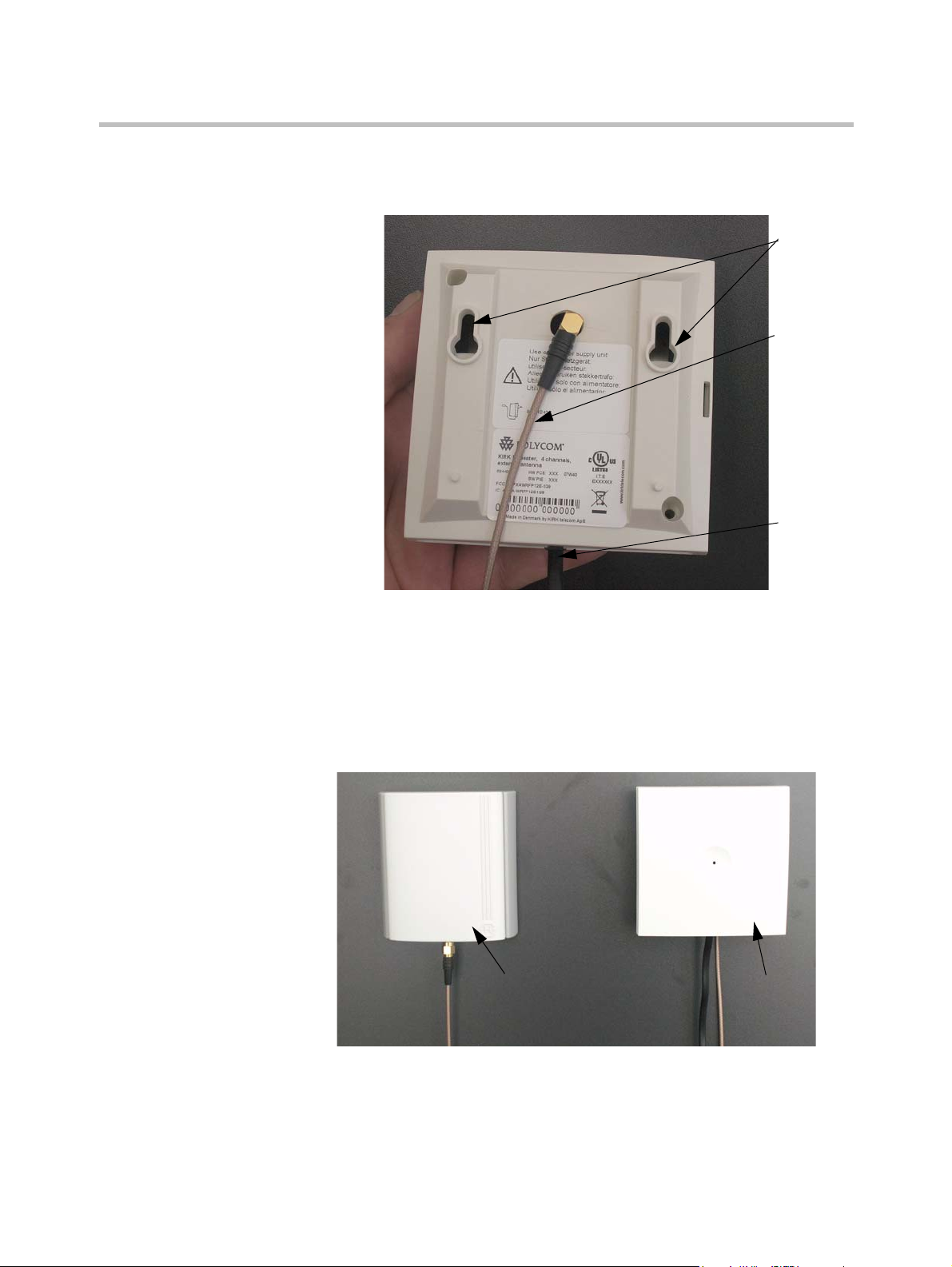
RepeaterExternal Antenna
(Only for repeaters supplied
with external antenna
connection)
Figure 1-2 Connect Power to the Bottom of the Repeater and External Antenna
Cable to the Rear of the Repeater
Holes for
wall
mounted
screws
External
antenna
cable (only
for repeaters
supplied
with
external
antenna
connection
Power
supply
cable
1 Connect the power supply cable into the RJ11 connector in the bottom of
the repeater. For repeaters with external antenna, connect the external
antenna cable to the antenna connector in the rear of the repeater as well.
2 Mount the repeater onto the wall using the screws accompanying the
repeater.
Figure 1-3 Repeater and External Antenna Installed on the Wall
1–6
Page 10

Note: The external antenna used for the transmitter is to be
fixed-mounted on indoor permanent structures providing a separation
distance of at least 20 cm / 8 inches from all persons during normal
operation and must not be co-located or operating in conjunction with
any other antenna or transmitter. The maximum radiated output power is
1W e.i.r.p. For more information and technical support, please refer to
www.polycom.com.
Recording the Installation Information
After completing the installation of the repeaters, record the location of each
repeater.
Checking Indicators
Verify that the repeater LED indicator is continuously on, indicating that the
repeater is functional.
Installing KIRK Repeater
Powering the KIRK Repeater
Power Options
The power supply for the repeater is 9VDC, 300mA.
Programming a KIRK Repeater with the KIRK Programming Kit
This section provides information about:
• “Content of the KIRK Programming Kit Repeater” on page 1-7
• “Set up of the Hardware for Repeater Programming” on page 1-8
• “Programming the KIRK Repeater with the ServiceTool” on page 1-9
Content of the KIRK Programming Kit Repeater
The Programming Kit Repeater (Part no. 02319508) consists of:
1–7
Page 11

KIRK Repeater, Installation and Configuration Guide
Splitter
Serial cable
• splitter
• serial cable
Note
For programming the repeater you also need the programming software
(ServiceTool) and the power supply for the repeater. The ServiceTool is
not part of the Programming Kit Repeater but can be downloaded from
www.polycom.com. The power supply for the repeater is to be ordered
separately (Part no. UK version: 84642421, Part no. EU version:
84642420, Part no. US version: 84642432).
Figure 1-4 Programming Kit Repeater
Set up of the Hardware for Repeater Programming
1 Unplug the repeater power supply and insert the splitter.
2 Connect the repeater power supply to the splitter and the mains. LED
flashes.
Note: Ensure that you have the appropriate power supply for the local
requirements.
3 Connect the serial cable to the splitter and Com port of your computer.
The repeater is now ready for programming via the ServiceTool.
Note: The above mentioned order of the set up (point 1, 2 and 3) is
important.
1–8
Page 12

Programming the KIRK Repeater with the ServiceTool
The ServiceTool is the tool you access from your desktop and use for repeater
programming, handset adjustment and software download to the handset and
repeater.
The ServiceTool identifies the type of repeater, and with this software it is
possible to program the KIRK Repeater to connect to the KIRK DECT Radio
Infrastructure solutions.
Before you start programming the repeater, ensure that the repeater is
connected to the computer and the mains.
In a single cell solution the numbers assigned to the repeaters must be between
2 and 7. The number of the base station is default set to 1.
In a multi cell solution, the numbering of the base stations and repeaters has to
follow the numbering in the table below.
Table 1-2 Repeater Numbering in a Multi Cell Solution
Base Station Repeater 1 Repeater 2 Repeater 3
0 64 128 192
1 65 129 193
2 66 130 194
3 67 131 195
4 68 132 196
5 69 133 197
6 70 134 198
7 71 135 199
8 72 136 200
9 73 137 201
10 74 138 202
11 75 139 203
12 76 140 204
13 77 141 205
14 78 142 206
15 79 143 207
16 80 144 208
17 81 145 209
18 82 146 210
19 83 147 211
20 84 148 212
21 85 149 213
Installing KIRK Repeater
1–9
Page 13

KIRK Repeater, Installation and Configuration Guide
Table 1-2 Repeater Numbering in a Multi Cell Solution
Base Station Repeater 1 Repeater 2 Repeater 3
22 86 150 214
23 87 151 215
24 88 152 216
25 89 153 217
26 90 154 218
27 91 155 219
28 92 156 220
29 93 157 221
30 94 158 222
31 95 159 223
32 96 160 224
33 97 161 225
34 98 162 226
35 99 163 227
36 100 164 228
37 101 165 229
38 102 166 230
39 103 167 231
40 104 168 232
41 105 169 233
42 106 170 234
43 107 171 235
44 108 172 236
45 109 173 237
46 110 174 238
47 111 175 239
48 112 176 240
49 113 177 241
50 114 178 242
51 115 179 243
52 116 180 244
53 117 181 245
54 118 182 246
55 119 183 247
56 120 184 248
1–10
Page 14

Table 1-2 Repeater Numbering in a Multi Cell Solution
Base Station Repeater 1 Repeater 2 Repeater 3
57 121 185 249
58 122 186 250
59 123 187 251
60 124 188 252
61 125 189 253
62 126 190 254
63 127 191 255
64 128 192 0
65 129 193 1
66 130 194 2
67 131 195 3
68 132 196 4
69 133 197 5
70 134 198 6
71 135 199 7
72 136 200 8
73 137 201 9
74 138 202 10
75 139 203 11
76 140 204 12
77 141 205 13
78 142 206 14
79 143 207 15
80 144 208 16
81 145 209 17
82 146 210 18
83 147 211 19
84 148 212 20
85 149 213 21
86 150 214 22
87 151 215 23
88 152 216 24
89 153 217 25
90 154 218 26
91 155 219 27
Installing KIRK Repeater
1–11
Page 15

KIRK Repeater, Installation and Configuration Guide
Table 1-2 Repeater Numbering in a Multi Cell Solution
Base Station Repeater 1 Repeater 2 Repeater 3
92 156 220 28
93 157 221 29
94 158 222 30
95 159 223 31
96 160 224 32
97 161 225 33
98 162 226 34
99 163 227 35
100 164 228 36
101 165 229 37
102 166 230 38
103 167 231 39
104 168 232 40
105 169 233 41
106 170 234 42
107 171 235 43
108 172 236 44
109 173 237 45
110 174 238 46
111 175 239 47
112 176 240 48
113 177 241 49
114 178 242 50
115 179 243 51
116 180 244 52
117 181 245 53
118 182 246 54
119 183 247 55
120 184 248 56
121 185 249 57
122 186 250 58
123 187 251 59
124 188 252 60
125 189 253 61
126 190 254 62
1–12
Page 16

Table 1-2 Repeater Numbering in a Multi Cell Solution
Base Station Repeater 1 Repeater 2 Repeater 3
127 191 255 63
128 192 0 64
129 193 1 65
130 194 2 66
131 195 3 67
132 196 4 68
133 197 5 69
134 198 6 70
135 199 7 71
136 200 8 72
137 201 9 73
138 202 10 74
139 203 11 75
140 204 12 76
141 205 13 77
142 206 14 78
143 207 15 79
144 208 16 80
145 209 17 81
146 210 18 82
147 211 19 83
148 212 20 84
149 213 21 85
150 214 22 86
151 215 23 87
152 216 24 88
153 217 25 89
154 218 26 90
155 219 27 91
156 220 28 92
157 221 29 93
158 222 30 94
159 223 31 95
160 224 32 96
161 225 33 97
Installing KIRK Repeater
1–13
Page 17

KIRK Repeater, Installation and Configuration Guide
Table 1-2 Repeater Numbering in a Multi Cell Solution
Base Station Repeater 1 Repeater 2 Repeater 3
162 226 34 98
163 227 35 99
164 228 36 100
165 229 37 101
166 230 38 102
167 231 39 103
168 232 40 104
169 233 41 105
170 234 42 106
171 235 43 107
172 236 44 108
173 237 45 109
174 238 46 110
175 239 47 111
176 240 48 112
177 241 49 113
178 242 50 114
179 243 51 115
180 244 52 116
181 245 53 117
182 246 54 118
183 247 55 119
184 248 56 120
185 249 57 121
186 250 58 122
187 251 59 123
188 252 60 124
189 253 61 125
190 254 62 126
191 255 63 127
192 0 64 128
193 1 65 129
194 2 66 130
195 3 67 131
196 4 68 132
1–14
Page 18

Table 1-2 Repeater Numbering in a Multi Cell Solution
Base Station Repeater 1 Repeater 2 Repeater 3
197 5 69 133
198 6 70 134
199 7 71 135
200 8 72 136
201 9 73 137
202 10 74 138
203 11 75 139
204 12 76 140
205 13 77 141
206 14 78 142
207 15 79 143
208 16 80 144
209 17 81 145
210 18 82 146
211 19 83 147
212 20 84 148
213 21 85 149
214 22 86 150
215 23 87 151
216 24 88 152
217 25 89 153
218 26 90 154
219 27 91 155
220 28 92 156
221 29 93 157
222 30 94 158
223 31 95 159
224 32 96 160
225 33 97 161
226 34 98 162
227 35 99 163
228 36 100 164
229 37 101 165
230 38 102 166
231 39 103 167
Installing KIRK Repeater
1–15
Page 19

KIRK Repeater, Installation and Configuration Guide
Table 1-2 Repeater Numbering in a Multi Cell Solution
Base Station Repeater 1 Repeater 2 Repeater 3
232 40 104 168
233 41 105 169
234 42 106 170
235 43 107 171
236 44 108 172
237 45 109 173
238 46 110 174
239 47 111 175
240 48 112 176
241 49 113 177
242 50 114 178
243 51 115 179
244 52 116 180
245 53 117 181
246 54 118 182
247 55 119 183
248 56 120 184
249 57 121 185
250 58 122 186
251 59 123 187
252 60 124 188
253 61 125 189
254 62 126 190
255 63 127 191
1–16
Note
Repeater and base station numbers must not be the same. Neither can the
repeater have a number similar to another base station or another repeater
in a situation where common overlap is present between the actual units
(Numbers with red colour show where numbering could be identical
between different units). If this occurs, handover between the different
units is not possible.
Page 20

Installing KIRK Repeater
Table 1-3 Example of a Normal Base Station/Repeater Configuration
Numbering of base stations and repeaters in a normal configuration
First repeater No. of base station + 64
Base to synchronize on: Number of base station
Second repeater No. of base station + 128
Base to synchronize on: Number of base station
Third repeater No. of base station + 192
Base to synchronize on: Number of base station
Table 1-4 Example of Repeater Jump Configuration
Numbering of repeaters in a repeate r jump configuration
First repeater in chain No. of base station + 64
Base to synchronize on: Number of base station
Second repeater in chain No. of base station + 128
Base to synchronize on: Number of previous repeater
Third repeater in chain No. of base station + 192
Base to synchronize on: Number of previous repeater
For more information about programming the repeater with the ServiceTool,
refer to the Help File in the ServiceTool. The ServiceTool is to be downloaded
from www.polycom.com.
1–17
Page 21

KIRK Repeater, Installation and Configuration Guide
Base Station
Radio Link
Use of KIRK Repeaters
without External Antenna
Use of KIRK Repeater with external Antenna
Use of KIRK Repeater With External Antenna
If radio coverage between a base station and a repeater is not needed, it is
possible to synchronize between the radio units using a repeater with external
antenna.
Figure 1-5 Use of Repeaters
Synchronization Ways
The distance from the repeaters without external antenna to the base station
must correspond to a RSSI loss of maximum 25dB.
Be aware that inside the area named “radio link” there is no radio coverage,
and therefore a wireless handset cannot be used in this area.
The distance between the base station and the repeater with external antenna
depends on the type of antenna used as well as on the signal attenuation
created by surroundings such as buildings, trees, etc.
The repeater with external antenna, 4 channels, can be programmed to obtain
synchronization on two radio units (base station, wireless server or repeater).
If a situation occurs where the primary sync for some reason breaks down, the
repeater will obtain sync on the alternative sync.
Be aware that the primary sync has priority; the alternative sync is only in use
as long as the primary sync is down.
1–18
Page 22

Regulatory Notices
This section contains important safety regulations for the KIRK Repeaters.
International Regulatory and Product Information
This KIRK product has been
marked with the CE mark. This
mark indicates compliance with
EEC Directives 89/336/EEC,
73/23/EEC 1999/5/EC. A full
copy of the Declaration of
conformity can be obtained from
Polycom Ltd, 270 Bath Road,
Slough, Berkshire, SL1 4DX, UK.
2
The WEEE Marking on this
equipment indicates that the
product must not be disposed of
with unsorted waste, but must be
collected separately.
Cesky [Czech]: Polycom (UK) Ltd tímto prohlašuje, že tento KIRK
Repeater je ve shode se základními požadavky a
dalšími príslušnými ustanoveními smernice
1999/5/ES.
Dansk [Danish]: Undertegnede Polycom (UK) Ltd erklærer herved, at
følgende KIRK Repeater overholder de væsentlige
krav og øvrige relevante krav i direktiv 1999/5/EF.
2–1
Page 23

KIRK Repeater, Installation and Configuration Guide
Deutsch
[German]:
Hiermit erklärt Polycom (UK) Ltd, dass sich das
Gerät KIRK Repeater in Übereinstimmung mit den
grundlegenden Anforderungen und den übrigen
einschlägigen Bestimmungen der Richtlinie
1999/5/EG befindet.
Eesti [Estonian]: Käesolevaga kinnitab Polycom (UK) Ltd seadme
KIRK Repeater vastavust direktiivi 1999/5/EÜ
põhinõuetele ja nimetatud direktiivist tulenevatele
teistele asjakohastele sätetele.
English: Hereby, Polycom (UK) Ltd. declares that this KIRK
Repeater is in compliance with the essential
requirements and other relevant provisions of
Directive 1999/5/EC.
Español
[Spanish]:
Por medio de la presente Polycom (UK) Ltd declara
que el KIRK Repeater cumple con los requisitos
esenciales y cualesquiera otras disposiciones
aplicables o exigibles de la Directiva 1999/5/CE.
Ελληνική
[Greek]:
ΜΕ ΤΗΝ ΠΑΡΟΥΣΑ Polycom (UK) Ltd ΔΗΛΩΝΕΙ
ΟΤΙ KIRK Repeater ΣΥΜΜΟΡΦΩΝΕΤΑΙ ΠΡΟΣ
ΤΙΣ ΟΥΣΙΩΔΕΙΣ ΑΠΑΙΤΗΣΕΙΣ ΚΑΙ ΤΙΣ ΛΟΙΠΕΣ
ΣΧΕΤΙΚΕΣ ΔΙΑΤΑΞΕΙΣ ΤΗΣ ΟΔΗΓΙΑΣ
1999/5/ΕΚ.
Français
[French]:
Par la présente Polycom (UK) Ltd déclare que
l'appareil KIRK Repeater est conforme aux exigences
essentielles et aux autres dispositions pertinentes de
la directive 1999/5/CE.
Italiano [Italian]: Con la presente Polycom (UK) Ltd dichiara che
questo KIRK Repeater è conforme ai requisiti
essenziali ed alle altre disposizioni pertinenti stabilite
dalla direttiva 1999/5/CE.
Íslenska
(Icelandic):
Hér með lýsir Polycom (UK) Ltd yfir því að KIRK
Repeater er í samræmi við grunnkröfur og aðrar
kröfur, sem gerðar eru í tilskipun 1999/5/EC
Latviski
[Latvian]:
Ar šo Polycom (UK) Ltd deklare, ka KIRK Repeater
atbilst Direktivas 1999/5/EK butiskajam prasibam un
citiem ar to saistitajiem noteikumiem.
Lietuviu
[Lithuanian]:
Šiuo Polycom (UK) Ltd deklaruoja, kad šis KIRK
Repeater atitinka esminius reikalavimus ir kitas
1999/5/EB Direktyvos nuostatas.
Nederlands
[Dutch]:
Hierbij verklaart Polycom (UK) Ltd dat het toestel
KIRK Repeater in overeenstemming is met de
essentiële eisen en de andere relevante bepalingen
van richtlijn 1999/5/EG.
2–2
Page 24

Regulatory Notices
Malti [Maltese]: Hawnhekk, Polycom (UK) Ltd, jiddikjara li dan
KIRK Repeater jikkonforma mal-htigijiet essenzjali u
ma provvedimenti ohrajn relevanti li hemm
fid-Dirrettiva 1999/5/EC.
Magyar
[Hungarian]:
Alulírott, Polycom (UK) Ltd nyilatkozom, hogy a
KIRK Repeater megfelel a vonatkozó alapvetõ
követelményeknek és az 1999/5/EC irányelv egyéb
elõírásainak.
Norsk
[Norwegian]:
Polycom (UK) Ltd erklærer herved at utstyret KIRK
Repeater er i samsvar med de grunnleggende krav og
øvrige relevante krav i direktiv 1999/5/EF.
Polski [Polish]: Niniejszym Polycom (UK) Ltd oswiadcza, ze KIRK
Repeater jest zgodne z zasadniczymi wymaganiami
oraz innymi stosownymi postanowieniami
Dyrektywy 1999/5/WE
Português
[Portuguese]:
Polycom (UK) Ltd declara que este KIRK Repeater
está conforme com os requisitos essenciais e outras
disposições da Directiva 1999/5/CE.
Slovensko
[Slovenian]:
Polycom (UK) Ltd izjavlja, da je ta KIRK Repeater v
skladu z bistvenimi zahtevami in ostalimi
relevantnimi dolocili direktive 1999/5/ES.
Slovensky
[Slovak]:
Polycom (UK) Ltd týmto vyhlasuje, že KIRK
Repeater splna základné požiadavky a všetky
príslušné ustanovenia Smernice 1999/5/ES.
Suomi [Finnish]: Polycom (UK) Ltd vakuuttaa täten että KIRK
Repeater tyyppinen laite on direktiivin 1999/5/EY
oleellisten vaatimusten ja sitä koskevien direktiivin
muiden ehtojen mukainen.
Svenska
[Swedish]:
Härmed intygar Polycom (UK) Ltd att denna KIRK
Repeater står i överensstämmelse med de väsentliga
egenskapskrav och övriga relevanta bestämmelser
som framgår av direktiv 1999/5/EG.
Explosive Device Proximity Warning
Warning. Do not operate your wireless network device
near unshielded blasting caps or in an explosive
environment unless the device has been modified to be
especially qualified for such use.
2–3
Page 25

KIRK Repeater, Installation and Configuration Guide
Waarschuwin g Gebruik dit draadloos netwerkapparaat alleen in de
Varoitus Älä käytä johdotonta verkkolaitetta
Attention Ne jamais utiliser un équipement de réseau sans fil
Warnung Benutzen Sie Ihr drahtloses Netzwerkgerät nicht in
buurt van onbeschermde ontstekers of in een
omgeving met explosieven indien het apparaat
speciaal is aangepast om aan de eisen voor een
dergelijk gebruik te voldoen.
suojaamattomien räjäytysnallien läheisyydessä tai
räjäytysalueella, jos laitetta ei ole erityisesti
muunnettu sopivaksi sellaiseen käyttöön.oen.
à proximité d'un détonateur non blindé ou dans un
lieu présentant des risques d'explosion, sauf si
l'équipement a été modifié à cet effet.
der Nähe ungeschützter Sprengkapseln oder
anderer explosiver Stoffe, es sei denn, Ihr Gerät
wurde eigens für diesen Gebrauch modifiziert und
bestimmt.
Avvertenza Non utilizzare la periferica di rete senza fili in
prossimità di un detonatore non protetto o di
esplosivi a meno che la periferica non sia stata
modificata a tale proposito.
Advarsel ikke bruk den trådløse nettverksenheten nært inntil
uisolerte fenghetter eller i et eksplosivt miljø med
mindre enheten er modifisert slik at den tåler slik
bruk.
Aviso Não opere o dispositivo de rede sem fios perto de
cápsulas explosivas não protegidas ou num
ambiente explosivo, a não ser que o dispositivo
tenha sido modificado para se qualificar
especialmente para essa utilização.
¡Advertencia! No utilizar un aparato de la red sin cable cerca de
un detonador que no esté protegido ni tampoco en
un entorno explosivo a menos que el aparato haya
sido modificado con ese fin.
Varning! Använd inte den trådlösa nätverksenheten i
närheten av oskyddade tändhattar eller i en
explosiv miljö om inte enheten modifierats för att
kunna användas i sådana sammanhang.
2–4
Page 26

Regulatory Notices
Appropriate RF
safety/installation information
The repeater is intended to be installed by authorized personal. The repeater shall be installed in
accordance with FCC rules.
WARNING
This is a class A product. In a domestic environment this product may cause radio
interference in which case the user may be required to take adequate measures.
The above warning is inserted for regulatory reasons. If any customer believes
that they have an interference problem, either because their KIRK product seems
to cause interference or suffers from interference, they should contact their
distributor immediately. The distributor will assist with a remedy for any problems
and, if necessary, will have full support from Polycom.
Safety
WARNING!
Only qualified service personnel may install this equipment. The instructions in this
manual are intended for use by qualified service personnel only.
Only qualified persons should service the system.
The installation and service of this hardware is to be performed only by service
personnel having appropriate training and experience necessary to be aware of
hazards to which they are exposed in performing a task and of measures to minimize
the danger to themselves or other persons.
Electrical shock hazards from the telecommunication network and AC mains are
possible with this equipment. To minimize risk to service personnel and users, the
system must be connected to an outlet with a third-wire Earth.
Service personnel must be alert to the possibility of high leakage currents becoming
available on metal system surfaces during power line fault events near network lines.
These leakage currents normally safely flow to Protective Earth via the power cord.
Therefore, it is mandatory that connection to an earthed outlet is performed first and
removed last when cabling to the unit. Specifically, operations requiring the unit to be
powered down must have the network connections (exchange lines) removed first.
2–5
Page 27

KIRK Repeater, Installation and Configuration Guide
Important Safety Instructions and Product Information
Before using your telephone equipment, you should always follow basic
safety instruction to reduce the risk of fire, electrical shock and injury to
persons, and damage to property.
1 Read and understand all instructions
2 Follow all warnings and instructions including those marked on the
product
3 Unplug this product before cleaning. Do not use liquid cleaners or
aerosol cleaners. Use damp cloth for cleaning
4 Do not install the telephone equipment in the bathroom or near a wash
bowl, kitchen sink, or laundry tub, in a wet basement, or near a
swimming pool
5 The product should be operated only from the type of power source
indicated on the instructions. If you are not sure of the type of power
supply, consult your dealer or local power company.
6 Do not overload wall outlets and extension cords as this can result in fire
or electrical shock.
7 Never push objects of any kind into this product through cabinet slots as
they may touch dangerous voltage points or short out parts that could
result in fire, electrical shock, or injury. Never spill liquid of any kind into
this product.
8 To reduce the risk of electrical shock or burns, do not disassemble this
product. Opening or removing covers may expose you to dangerous
voltages, dangerous electrical current, or other risks. Incorrect reassemble
can cause electrical shock when the appliance is subsequently used. If the
product need repair, consult your dealer.
9 This product does not support coneections to outside plant.
10 Refer servicing to qualified service personnel under the following
conditions:
If liquid has been spilled into the product
If the product has been exposed to rain or water
If the product does not operate normally when following the operating
instructions in the manual. Adjust only those controls that are covered by
the operation instructions. Improper adjustment of other controls may
result in damage and will often require extensive work by qualified
service personnel to restore the product to normal operation.
If the product has been dropped or cabinet has been damaged
If the product exhibits a distinct change in performance
2–6
11 Avoid using telephone during an electrical storm. There may be a risk of
electrical shock from lightning
Page 28

Regulatory Notices
12 Do not use the telephone to report a gas leak in the vicinity of the leak
13 Do not place the unit near microwave ovens, radio equipment, or
non-ground connected televisions. These appliances may cause electrical
interference to the base or handset
14 The unit must be installed on a hard, plane surface and connected to a
functional 120 volt AC power net adapter and plug the adapter into the
power outlet
15 The system will not operate in the event of a blackout. Please keep a
backup phone for emergencies
Intrinsic safety
Do not install the unit in conditions where there is a danger of electrically
ignited explosions.
Exposure to sunlight, heat and moisture
Do not expose the unit to direct sunlight for long periods. Keep away from
excessive heat and moisture.
Spare parts and accessories
Use only approved spare parts and accessories. The operation of
non-approved parts cannot be guaranteed and may even cause damage.
RF compliance information
The users manual or instruction manual for an intentional or unintentional
radiator shall caution the user that changes or modifications not expressly
approved by the party responsible for compliance could void the user’s
authority to operate the equipment.
NOTICES
FCC Note: This device complies with Part 15 of the FCC rules. Operation is
subject to the following two conditions: (1) This device may not cause harmful
interference, and (2) this device must accept any interference received,
including interference that may cause undesired operation.
IC Note: Operation is subject to the following two conditions: (1) This device
may not cause interference, and (2) this device must accept any interference,
including interference that may cause undesired operation of the device. The
term “IC:” before the certification /registration number only signifies that the
Industry Canada technical specifications were met.
2–7
Page 29

KIRK Repeater, Installation and Configuration Guide
Information to user: The users manual or instruction manual for an
intentional or unintentional radiator shall caution the user that changes or
modifications not expressly approved by the party responsible for compliance
could void the user’s authority to operate the equipment.
LIMITED WARRANTY
This limited, non-transferable warranty is provided to the original purchaser.
The product is warranted to be free from defects in materials and
workmanship under normal installation, use and service for a period of one (1)
year from the date of purchase as shown on the purchaser’s receipt.
Our obligation under this warranty is limited to repair or replacement (at our
option) of the product or any part(s) which are defective provided that the
product is returned to the original place of purchase or an authorized service
location during the warranty period. Products returned must be accompanied
by a copy of the purchase receipt. In the absence of a purchase receipt, the
warranty period shall be one (1) year from the date of manufacture. Repair or
replacement of the product is your sole and exclusive remedy.
If the product is repaired, reconditioned component parts or materials may be
used. If the product is replaced, we may replace it with a new or reconditioned
product of the same or similar design. The repaired product will be warranted
for either (a) 90 days or (b) the remainder of the original one (1) year warranty
period, whichever is longer.
This warranty does not apply to the defects outside of our control, including
but not limited to acts of God, fire, flood and damage while in transit to service
facility. We do not warranty that the product will be compatible with any
telephone equipment, systems or party lines.
This warranty shall be void if the product is damaged as a result of
defacement, misuse, abuse, neglect, accident, destruction or alteration of the
serial number, improper electrical voltages or currents, repair, alteration or
maintenance by any person or party other than our authorized service facility,
or any violation of instructions furnished by us.
This warranty is also void if this product is removed from the country in which
it was purchased by the original purchaser, if it is used in a country in which
it is not registered for use, or if it is used in a country for which it was not
designed. Due to variations in telephone systems and communications laws,
this product may be illegal for use in some countries. We assume no
responsibilities for damages or penalties incurred resulting from the use of this
product in a manner or location other than that for which it was intended.
THIS LIMITED WARRANTY IS IN LIEU OF ALL OTHER WARRANTIES
EXPRESS OR IMPLIED. ANY IMPLIED WARRANTIES INCLUDING BUT
NOT LIMITED TO THE IMPLIED WARRANTIES OF MERCHANTABILITY
AND FITNESS FOR A PARTICULAR PURPOSE, SHALL BE LIMITED TO
THE DURATION OF THIS WRITTEN LIMITED WARRANTY. WE
DISCLAIM ANY LIABILITY FOR DAMAGES FOR LOSS OF USE OF THE
PRODUCTS, LOSS OF TIME, INCONVENIENCE, INJURY TO ANY
2–8
Page 30

Regulatory Notices
PERSON, OR DAMAGE TO PROPERTY CAUSED BY THE PRODUCT, LOSS
OF REVENUE OR PROFIT OR DAMAGES FOR ANY FAILURE TO
PERFORM. IN NO EVENT SHALL WE BE LIABLE FOR ANY SPECIAL,
INCIDENTAL, PUNITIVE OR CONSEQUENTIAL DAMAGES EVEN IF WE
ARE ADVISED OF THE POSSIBILITY OF SUCH DAMAGES.
Some states do not allow limitations on how long an implied warranty lasts,
so the above limitations may not apply to you. This warranty is the sole and
exclusive warranty provided for the product. There are no other express
warranties. This warranty gives you specific legal rights, and you may also
have other rights, which vary from state to state.
2–9
Page 31

KIRK Repeater, Installation and Configuration Guide
2–10
 Loading...