

Page 1

Alcatel–Polycom Video Telephony:
IP Touch Instant Video Solution
Deployment Guide
Phase 1
Page 2

Copyright © 2006 Polycom, Inc.
All Rights Reserved
Catalog No. DOC2332A
Ve r s i o n 1. 0
Proprietary and Confidential
The information contained herein is the sole intellectual property of Polycom, Inc. and Alcatel. No distribution, reproduction or
unauthorized use of these materials is permitted without the expressed written consent of Polycom, Inc. and Alcatel. Information
contained herein is subject to change without notice and does not represent commitment of any type on the part of Polycom, Inc.
and Alcatel. Polycom and Accord are registered trademarks of Polycom, Inc.
Notice
While reasonable effort was made to ensure that the information in this document was complete and accurate at the time of
printing, Polycom, Inc., cannot assume responsibility for any errors. Changes and/or corrections to the information contained in
this document may be incorporated into future issues.
Page 3

Alcatel Instant Video Solution Deployment Guide
Table of Contents
Overview . . . . . . . . . . . . . . . . . . . . . . . . . . . . . . . . 1-1
About this Guide .................................................................................... 1-3
Alcatel Components Configuration . . . . . . . . . . . . 2-1
Call Server - OmniPCX Enterprise Configuration ............................. 2-1
Prerequisites .................................................................................... 2-2
Global Configuration ..................................................................... 2-2
Trunk Group Management ........................................................... 2-6
SIP Gateway Management ............................................................ 2-8
SIP External Gateway Management ............................................ 2-8
Prefix Management ........................................................................ 2-9
Network Routing Table Management ....................................... 2-10
SIP Authentication Configuration ............................................. 2-10
SIP Users Declaration ........................................................... 2-11
Transfer Timer .............................................................................. 2-13
API Framework Configuration .......................................................... 2-15
Before you Begin ........................................................................... 2-15
Alcatel API Installation ................................................................ 2-16
FlexLM License File ...................................................................... 2-17
Services Configuration ................................................................. 2-17
Call Server Configuration ................................................... 2-17
Presentation Server Configuration .................................... 2-18
User Declaration in the Web Administration Tool .......... 2-19
IVAS Video Application ...................................................................... 2-20
IVAS Configuration ..................................................................... 2-21
Video Application Declaration ........................................... 2-21
IVAS (Omega) Parameters .................................................. 2-22
PRS Parameters ..................................................................... 2-23
Polycom RAS200A and SIP Parameters ............................ 2-24
Polycom Components Configuration . . . . . . . . . . . 3-1
Polycom RAS200A Configuration ....................................................... 3-1
Installing the Polycom RAS200A ................................................. 3-2
i
Page 4

Setting up the System Through the Internet .............................. 3-2
Configuring RAS200A Locally ............................................. 3-2
Configuring RAS200A using a web connection ................. 3-3
Configure the PC Network Settings to Connect RAS200A ...... 3-3
Logging in the First Time .............................................................. 3-4
Obtaining Software Licensing Information ................................ 3-7
Changing the Password ................................................................. 3-8
Viewing or Changing Profiles ...................................................... 3-9
Changing the Configuration ....................................................... 3-10
Setting up MGC Devices ............................................................. 3-12
PVX VOA Configuration ..................................................................... 3-14
PVX VOA Installation .................................................................. 3-14
Starting Polycom PVX VOA on Computer Startup ................. 3-15
Setting the PVX VOA to Auto Answer ..................................... 3-15
Specifying the Polycom RAS200A Settings .............................. 3-15
Specifying SIP Settings ................................................................ 3-16
VSX Configuration ............................................................................... 3-17
MGC Unit Configuration .................................................................... 3-19
Assigning Network Services to the IP/IP+ Cards ................... 3-37
Setting the Default IP Network Service .................................... 3-40
Testing and Validation . . . . . . . . . . . . . . . . . . . . . .4-1
Testing the Alcatel Components .......................................................... 4-1
API Framework .............................................................................. 4-1
Testing the Polycom Components ....................................................... 4-2
Before You Test ............................................................................... 4-2
Verifying the Polycom RAS200A Configuration and
Connectivity .................................................................................... 4-2
Communication Protocols and Ports Summary . . . 5-1
ii
Page 5
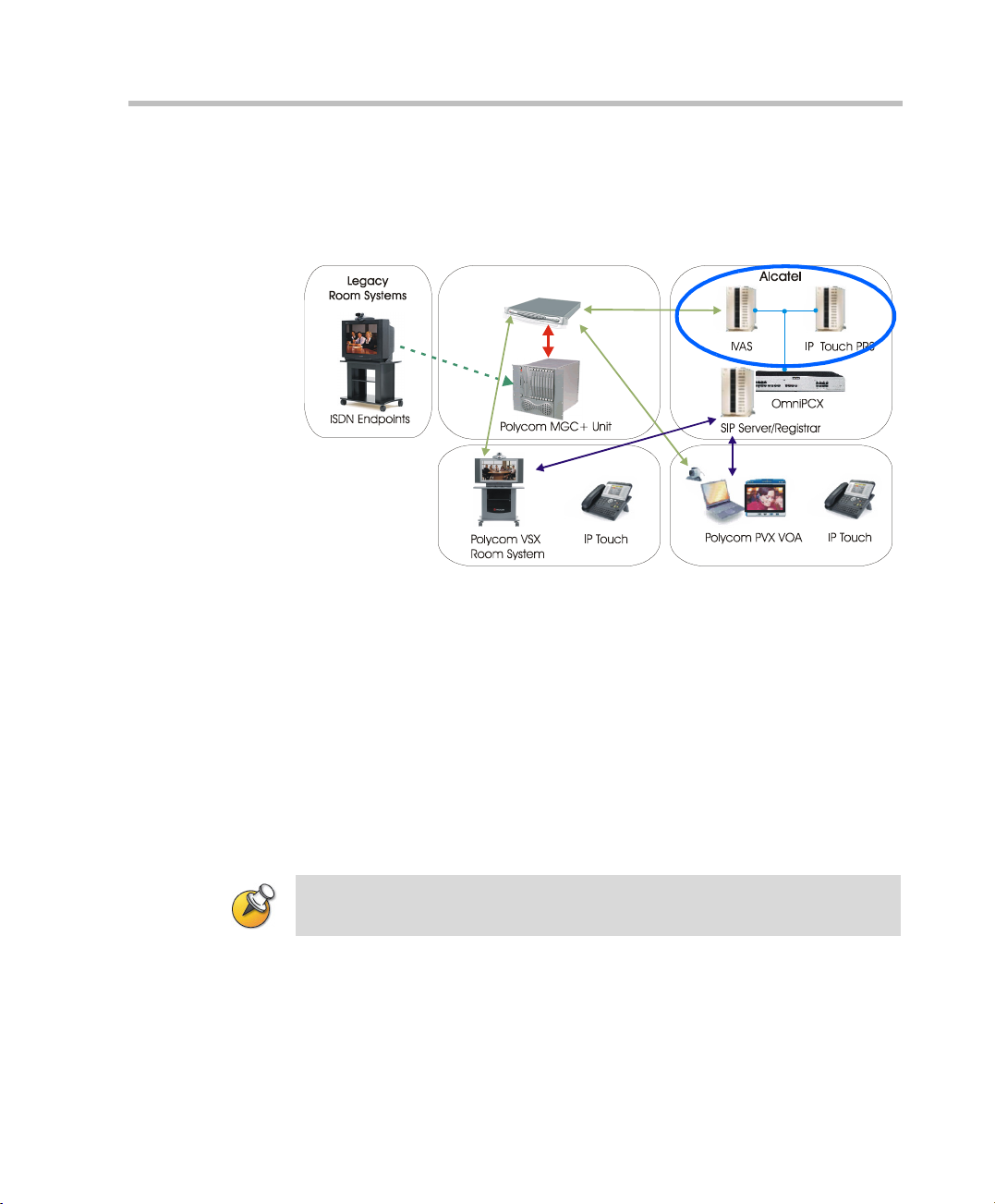
Overview
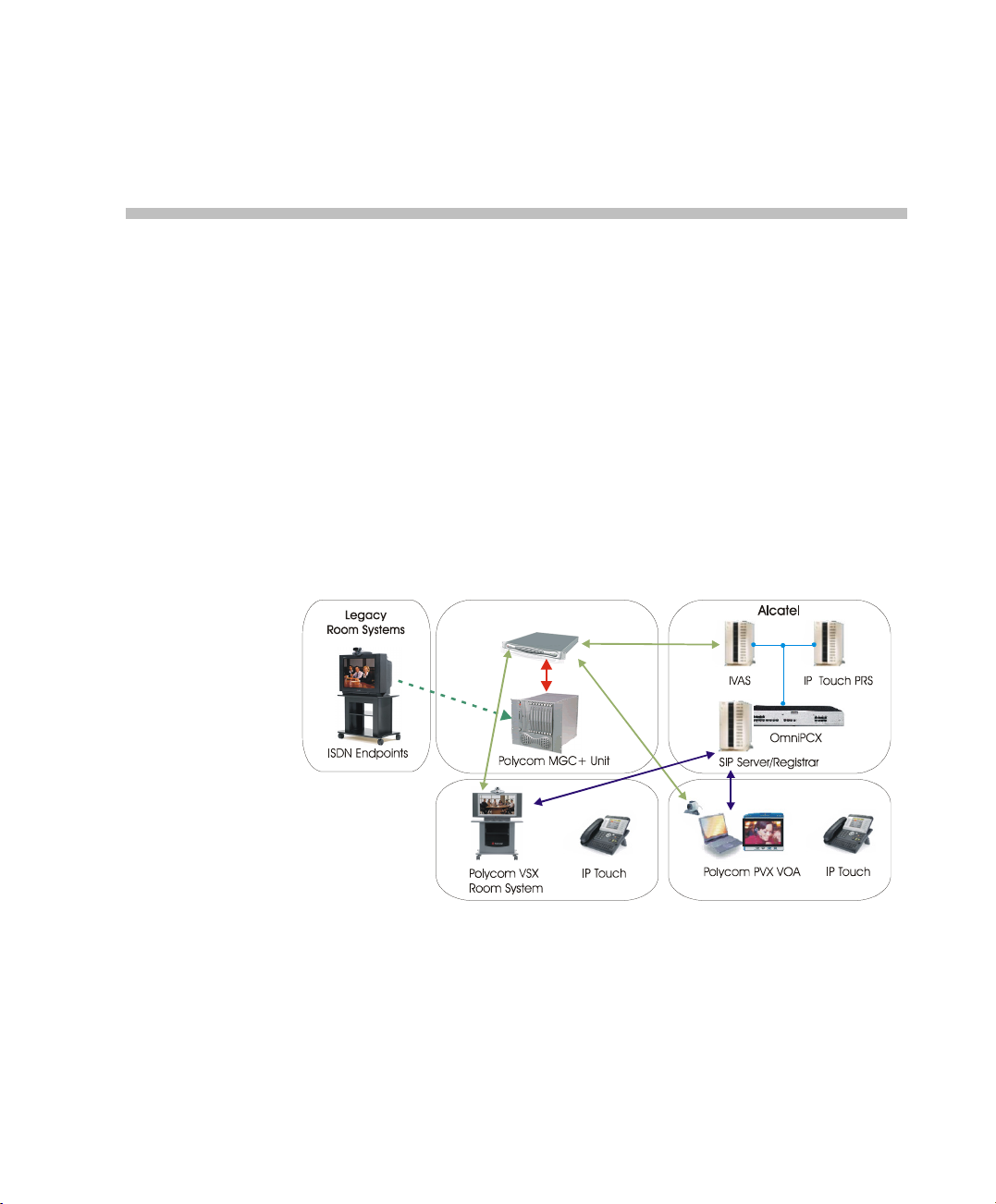
The Alcatel Instant Video Solution is a seamless integration of Alcatel IP
telephony with Polycom video conferencing systems that enables ondemand video conferencing from an IP Touch phone with Polycom PVX
VOA and VSX video endpoints. This solution is based on Alcatel IP Touch
phone connected to the OmniPCX Enterprise PBX and interfacing with
the Polycom components through the Alcatel IVAS server.
Polycom RAS200A is a Polycom Conferencing Application Server (PCAS)
functioning as the front-end and door way into the Polycom video
domain. It orchestrates the set up of P2P and multipoint video calls
involving Polycom video endpoints and MGC MCU(s).
1
Polycom RAS 200A
Figure 1-1 Solution Architecture
1-1
Page 6

Chapter 1-Overview
The following Polycom and Alcatel components are part of the integrated
solution:
Alcatel components:
• IVAS (Instant Video Application Server)
The application (a tomcat webapps) installed on a a separate server or
on top of the API Framework server. The IVAS server manages the
users and controls the application. In addition, it receives the
dynamic view of the IPTouch phone state (OTS), displays the
dynamic screens on the IPTouch phone (PRS), receives actions from
the IPTouch phone, and establishes the video communications via
Polycom RAS200A. IVAS initiates the video sessions through
Polycom RAS200A and receives video-related information and
notifications from the Polycom RAS200A.
• API Framework server
The following Alcatel components are used:
— FLEXLM (License server)
— PRS (Presentation server)
— OTS (Open Telephony Server)
The API Framework is included in the Omni Touch Unified
Communication application if this application is present.
— OmniPCX Enterprise Call Server
The Call Server manages the IP Touch phones and acts as SIP
Gateway and Proxy/Registrar for the solution
1-2
Polycom components:
• Polycom RAS200A (Polycom Conferencing Application Server PCAS)
It is the "doorway" to Polycom video scenarios, including P2P and
multipoint. Depending on the scenario being executed, Polycom
RAS200A interacts with the other Polycom components.
• Polycom PVX VOA (PVX Video Only Alcatel)
Polycom's desktop video application running on the user's PC. It is
managed by Polycom RAS200A and in this solution, it is associated
with the user's IPTouch phone. The PVX VOA P2P and multipoint
video call establishment / termination is controlled by Polycom
RAS200A.
Page 7

• Polycom VSX room systems
A family of high quality video room system devices that are used for
P2P and multipoint video calls.
•MGC Video MCU
A family of Audio/video MCUs such as MGC-25 and MGC+50/100.
In the Alcatel IP Touch Instant Video solution, the MGC unit’s task is
to host the multipoint video conferencing. In this solution (and
configuration), the MGC unit enables SIP and ISDN connections to
the same conference. Therefore the MGC unit can be used to bridge
the integrated environment with legacy equipment such as ISDN
video endpoints. The Polycom RAS200A interfaces with the MGC
unit through the MGC API. It can manage a pool of MGC MCUs,
making best use of the available conferencing resources allocating
conferences ad-hoc to run on most appropriate MGC.
About this Guide
This guide describes the steps required to upgrade the installed Alcatel
Network with (IPTouch phones) to video conferencing by adding the
required Polycom video components. It includes step-by-step instructions
for setting up the required Alcatel and Polycom components.
This guide is organized according to the required configuration
workflow, detailing the steps required to configure the Alcatel
components (Chapter 2) and the Polycom components (Chapter 3). In
addition, it describes the testing and validation processes to ensure
seamless operation of this solution (Chapter 4).
The following configuration procedures are described in the Alcatel
Instant Video Solution Deployment Guide:
Alcatel Instant Video Solution Deployment Guide
Chapter 2-Alcatel Side configuration
This chapter describes the steps and procedures required to modify the
configuration of the Alcatel components to add video to voice calls.
• Call Server - OmniPCX Enterprise configuration. It describes how to
create a SIP gateway and manage several IP Touch sets. It includes
the following steps:
— Global configuration
— Trunk group management
— SIP Gateway management
— SIP External Gateway management
1-3
Page 8

Chapter 1-Overview
— Prefix management
— Network routing table management
— SIP User declaration
— Transfer timer
• API Framework configuration. It details the steps required to deploy
an API Framework and to manage its services. It includes the
following steps:
— Running the API Setup program
— Services configuration
• Call Server configuration
• Presentation Server configuration
— Restart services
• User declaration in the Web Administration
• IVAS (Omega) Video Application
The goal is to deploy the third party framework using third party
installation with alcatelomega.xml deployment file and to manage
the Omega application. This installation is performed on a dedicated
system or API system whose name is <ThirdPartyHost>
— IVAS (Omega) configuration
1-4
Chapter 3 - Polycom side configuration
This chapter describes the steps and procedures required to configure the
Polycom RAS200A to the Alcatel environment and manage the
communication with the video endpoints as well as the conferencing
MCU. In addition, it describes the steps required to adjust the video
endpoint configuration to the Alcatel-Polycom integrated video solution.
• Video Management Components
— Polycom RAS200A installation
— Polycom RAS200A configuration
— Configuring the Unified Conferencing Bridge (MGC)
• Video Endpoint
— PVX VOA configuration
— VSX Configuration
Chapter 4 - Verification and Testing
This chapter describes the steps and procedures required to verify that the
Alcatel Instant Video Solution is configured correctly so P2P and
multipoint video can be carried out.
Page 9
Alcatel Components Configuration
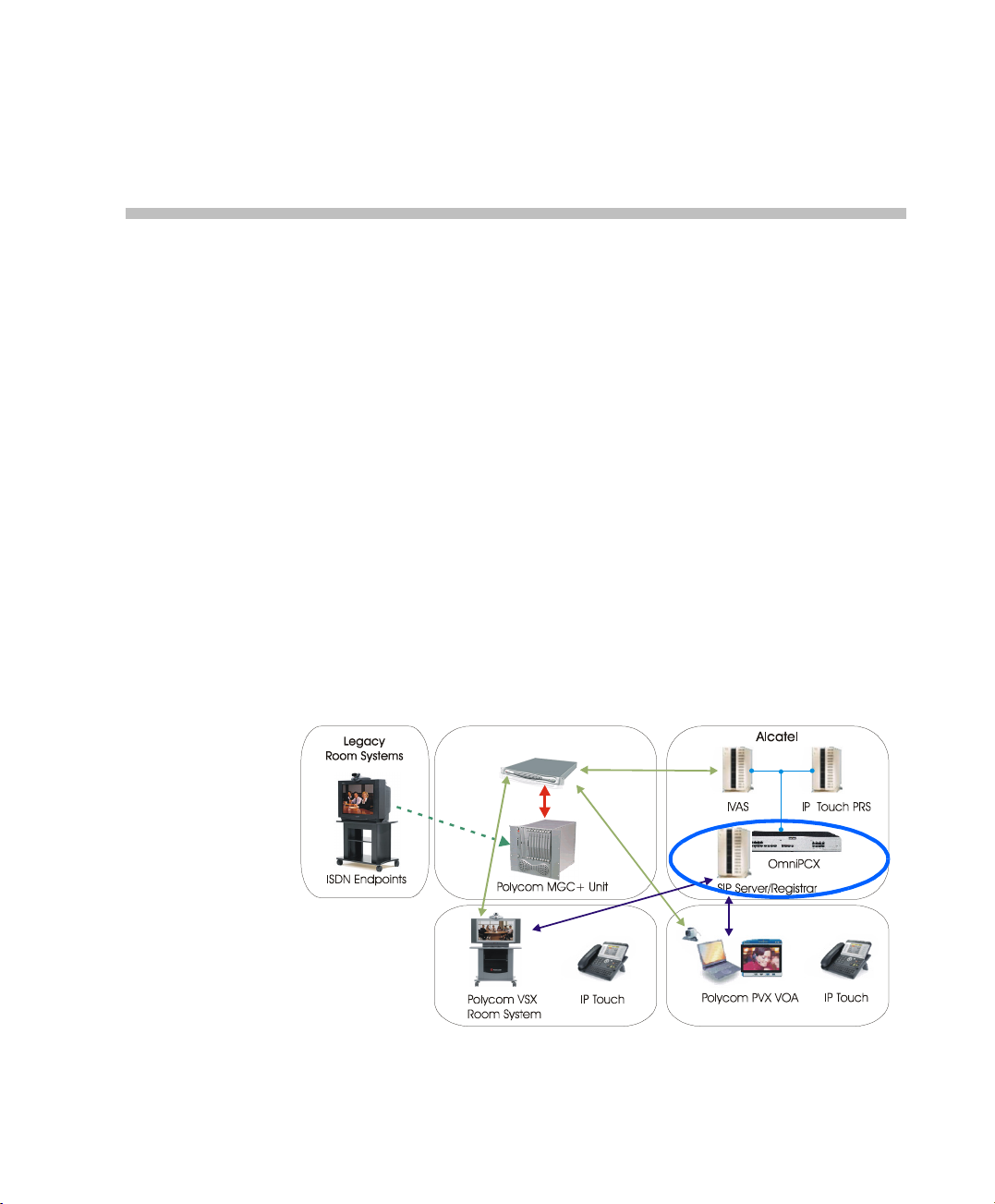
This chapter describes the steps and procedures required to add video
using Polycom components to an audio only installed Alcatel network in
which the OmniPCX and IP Touch phones are already installed and
configured. It assumes prior knowledge of the Alcatel environment and
its configuration.
Call Server - OmniPCX Enterprise Configuration
This section describes how to create a SIP gateway and manage several IP
touch sets.
2
Polycom RAS 200A
Figure 2-1 Solution Architecture
2-1
Page 10
Chapter 2-Alcatel Components Configuration
Prerequisites
To perform the following procedures the following hardware is required:
• A rack (3, 6 or 9 positions)
• A CS card (call handling server)
• A GD card in position 0 (Gateway CPU to have voice compressors)
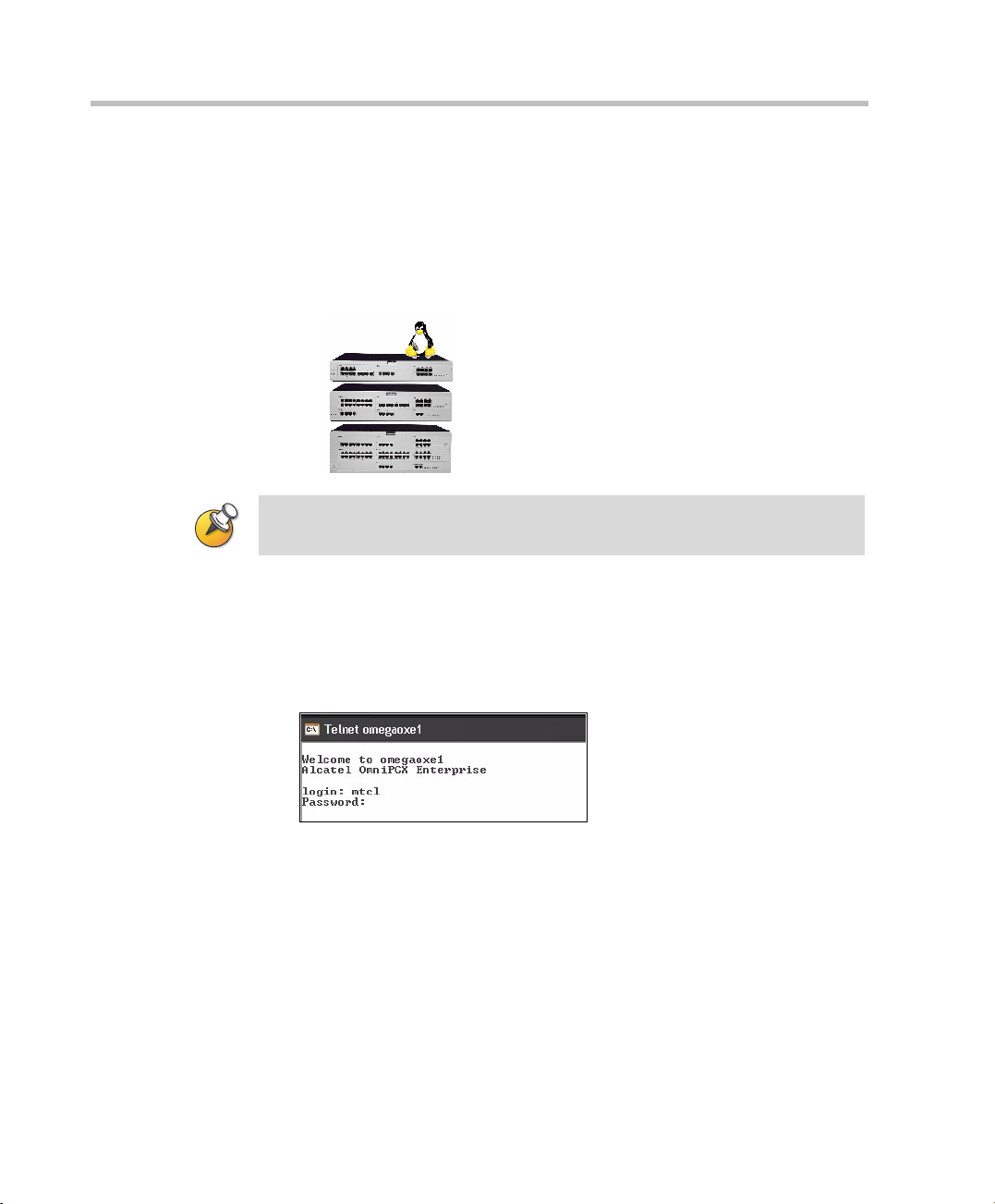
The Call Server software must be version R7.1f5.401.6 or later.
The solution is only supported on IP Touch phones 4068, 4038 or 4028.
Global Configuration
2-2
1 Connect to the call server using Telnet with the login name and
password provided by Alcatel.
telnet call_server_name.
Page 11
Alcatel Instant Video Solution Deployment Guide
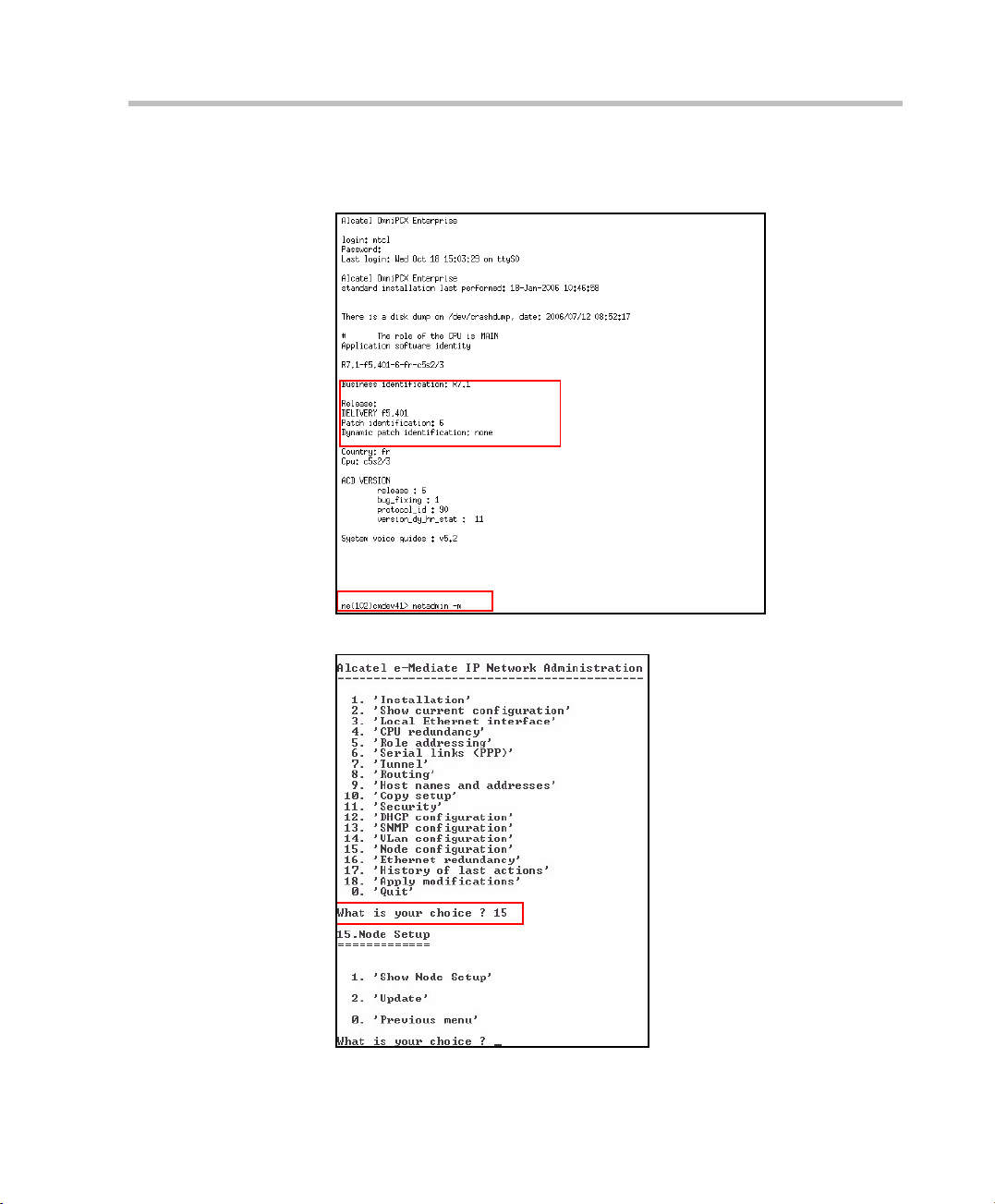
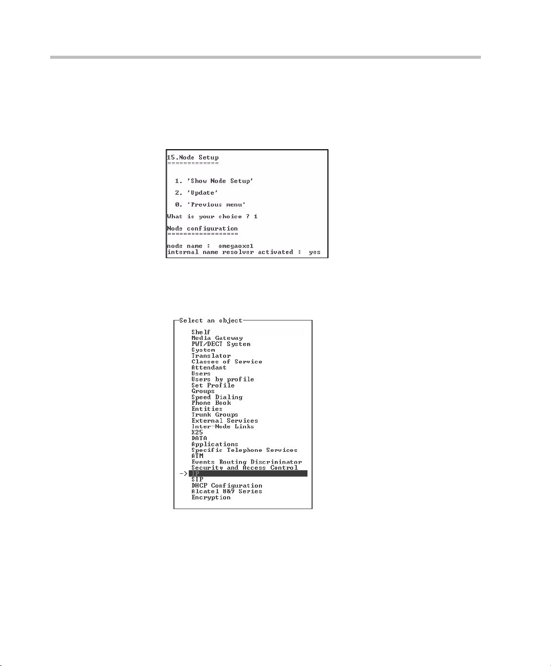
2 To configure the node, enter:
netadmin -m
3 Enter 15.
2-3
Page 12
Chapter 2-Alcatel Components Configuration
4 In the Node Setup, enter 1 to configure the Node.
5 In the Node Configuration, enter the node attributes as follows:
node name = call_server_name
Internal name resolver activated: yes
The following Call Server configuration procedure is performed using
“mgr”.
6 In the Object list, select IP > IP Parameters.
2-4
Page 13
Alcatel Instant Video Solution Deployment Guide
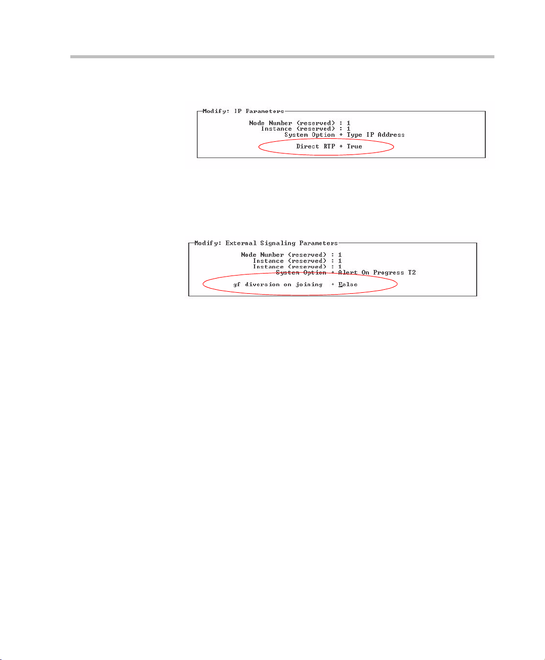
7 In the Modify IP Parameters, set the RTP direct field to True.
8 In the Object list, select System > Other System Param. > External
Signaling Parameters.
9 To ensure correct forwarding operation, set the parameter gf diversion
on joining to False.
2-5
Page 14

Chapter 2-Alcatel Components Configuration
Trunk Group Management
The following Call Server configuration procedure is performed using
“mgr”.
1 Create a trunk group. For example:
2-6
2 To manage virtual access, select Trunk groups > Trunk group >
Virtual access for SIP.
3 In the Number of SIP access field, enter 2.
Two SIP accesses allow 60 simultaneous calls for a trunk group.
Page 15

Alcatel Instant Video Solution Deployment Guide
4 In the IP compression type field, select G.711.
2-7
Page 16
Chapter 2-Alcatel Components Configuration
SIP Gateway Management
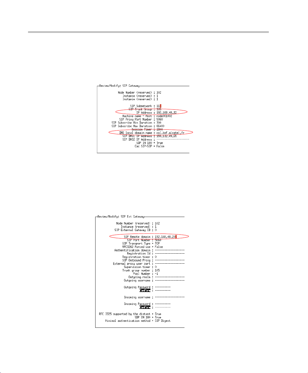
1 In the Objects list, select SIP > SIP Gateway.
2 Define the SIP Server IP Address and the DNS local domain name.
SIP External Gateway Management
1 In the Objects list, select SIP > External Gateways.
2 In the Remote domain field, enter the domain name of the Polycom
RAS200A. This address must be well informed in the Polycom
RAS200A host.
2-8
Page 17
Prefix Management
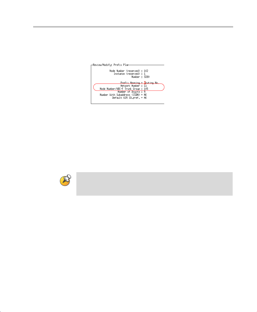
1 In the Objects list, select Translator > Prefix plan.
2 In the Network Number field, enter the subnetwork number of the SIP
gateway.
3 In the Trunk Group field, enter the number of the trunk group
previously created.
4 In the Number and Number of digits fields, provide the classification
plan. Here it is 2000 to 2099. This is the range of numbers to be used
to call the VSX. This range of numbers is used by IVAS and RAS200A
to initiate the transfer of the audio part when the video conference is
established from the IP-Touch (associated to the VSX) to the VSX.
Alcatel Instant Video Solution Deployment Guide
• The Prefix to use with VSX (routing table) must be in the range 0-9 and must
not include * # A B C D.
• The VSX prefix value is needed for the IVAS configuration, and thus must be
known before IVAS installation.
2-9
Page 18
Chapter 2-Alcatel Components Configuration
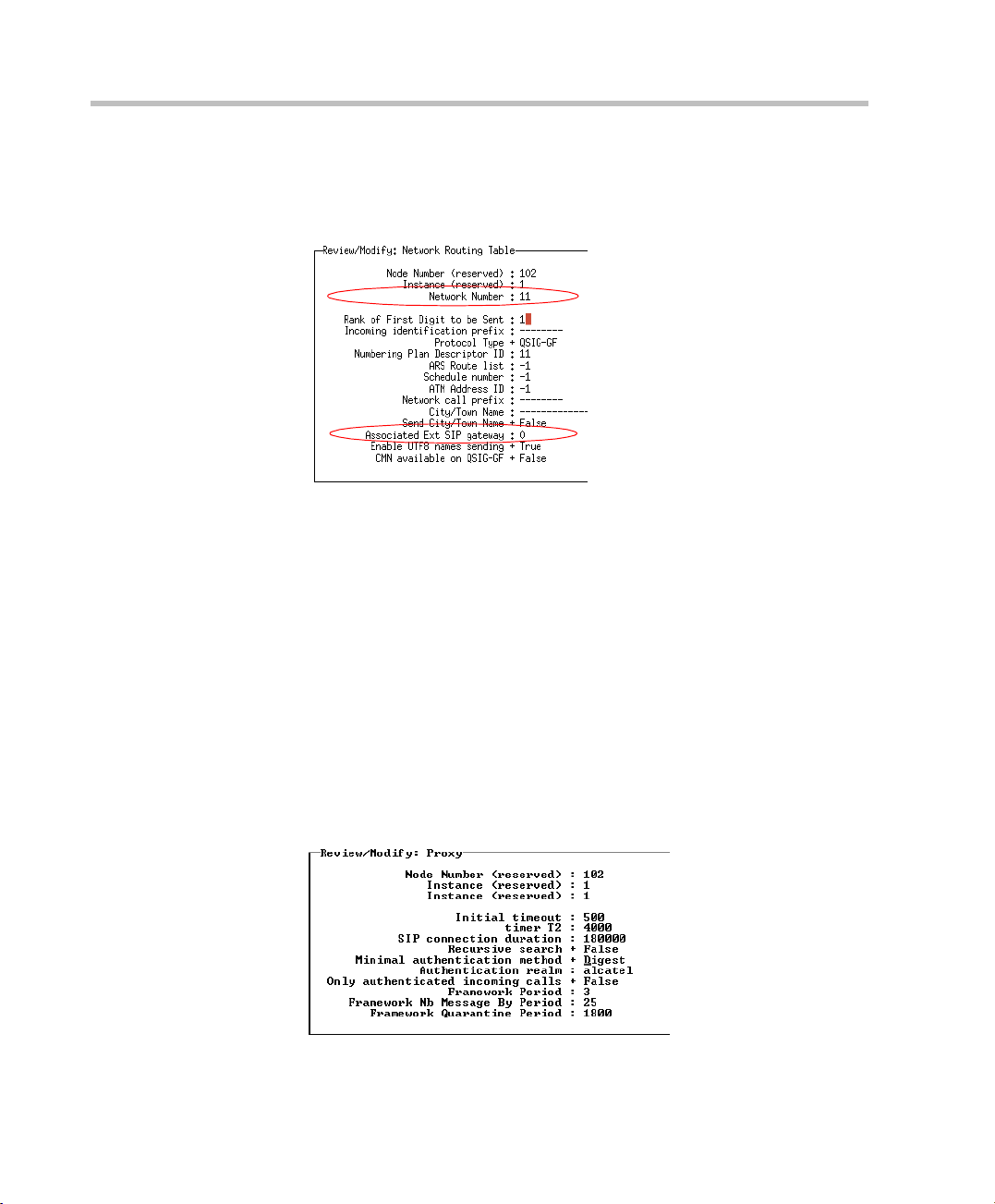
Network Routing Table Management
1 In the Objects list, select Translator > Network Routing Table.
2 In the Network Number field, enter the subnetwork number of the SIP
gateway.
3 In the Associated SIP gateway field, enter the instance of the external
gateway.
SIP Authentication Configuration
SIP authentication is not mandatory but recommended. Configure the SIP
proxy authentication:
1 In the Objects list, select SIP > Proxy.
2-10
Page 19
Alcatel Instant Video Solution Deployment Guide
2 In the Minimal authentication method field, select Digest.
3 In the Authentication realm, enter 50-character (maximum) string
describing the security domain on which users must authenticate
themselves.
SIP Users Declaration
When working in SIP \Authentication mode, each video-enabled user
must be defined (in Alcatel domain) so when registering with the SIP
server / registrar through the video client, the users are challenged for
authentication using their predefined user name / password (make sure
that SIP user licenses are available on the system). RAS200A (PCAS) must
also be defined as a user to be able to authenticate. Make sure that you set
it as a new user in the SIP proxy.
The MGC MCU is not "visible" / routable through the Alcatel SIP proxy
and holds all SIP communication through RAS200A.
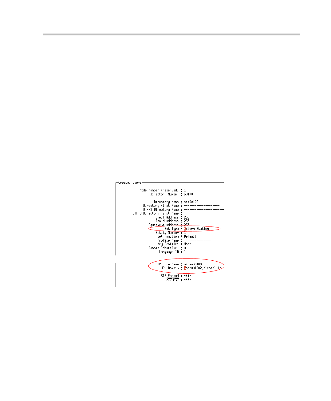
1 In the Objects list, select Users>Create.
2 In the Directory Number field, enter free number from OXE
numbering plan.
3 In the Set Type field, select Extern station
2-11
Page 20
Chapter 2-Alcatel Components Configuration
4 Verify the current fields.
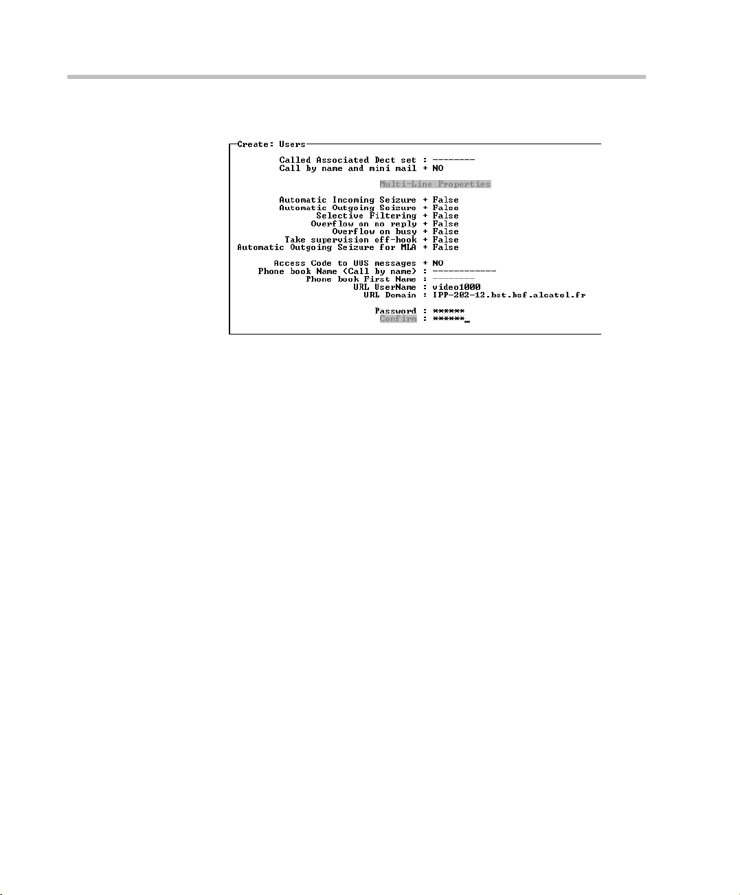
5 In the URL UserName field, enter the SIP name. When adding
RAS200A user, enter PCAS as the URL UserName.
6 In the URL Domain field, enter the SIP domain.
The URL UserName@URL Domain and password must be the same
as the URL and password defined in the video endpoint
configuration.
The default password for RAS200A is 123456. Enter this password
when defining a RAS200A user.
To modify the default password:
a login remotely to RAS200A and edit the following configuration
file: C:/Program Files/Polycom/Alcatel/bin/SipModule/cfg/
cs_private_cfg_rel.xml.
b Look for password tag under digest and change the default
123456 string to a new alphanumeric password.
c Save the file and reboot RAS200A server.
After modifying the password in RAS200A configuration file,
you must also change it for the RAS200A user you declared in
the SIP Proxy.
2-12
Page 21
Transfer Timer
The default Transfer Timer value must be changed if a VSX endpoint will
be used in this deployment.
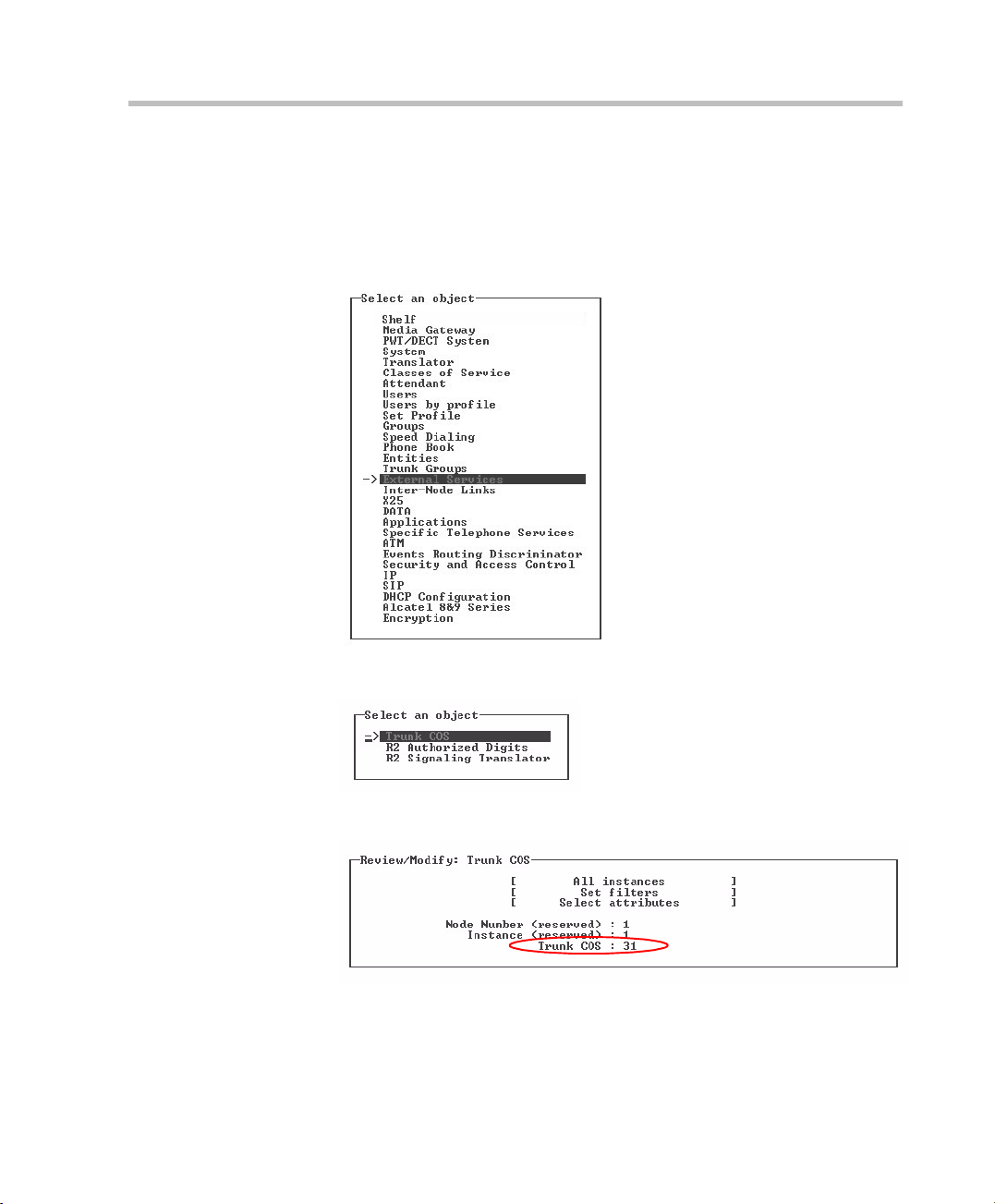
1 Using mgr, select External Services.
Alcatel Instant Video Solution Deployment Guide
2 Select Trunk COS.
3 In the Trunk COS field, enter 31 and confirm.
2-13
Page 22
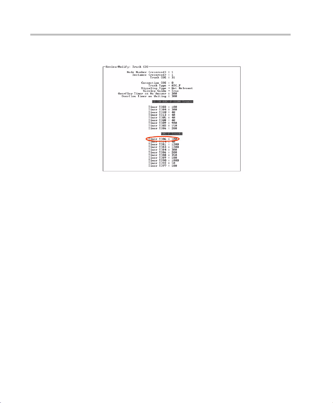
Chapter 2-Alcatel Components Configuration
4 Change the Timer T306 to 100 (instead of 40).
2-14
Page 23
Alcatel Instant Video Solution Deployment Guide
API Framework Configuration
This section describes how to deploy the API Framework and manage its
services.
Polycom RAS 200A
Before you Begin
• To install the software you must be logged in with Administrator
privileges.
• It is recommended to start the configuration procedure with a freshly
installed Windows 2003 Server.
• to start the administration part you must get a license file named
"alcotuc.lic".
• Uninstall IIS before beginning the installation. If the IIS components
are installed, they conflict with Apache2.
The software version is API Framework -R3.0.000.021, or
OTUC-R4.0.000.022a or later
2-15
Page 24

Chapter 2-Alcatel Components Configuration
Alcatel API Installation
Windows Services control Panel must be closed before installing the Alcatel API
software.
1 Insert the Alcatel API CDRom.
Installation wizard opens. If it doesn't, launch the installation process
using "setup.exe".
2 In the Welcome window appears. Click Next to continue.
3 Accept the license terms.
4 Select the installation modes: Expert or Update.
In the Update mode, a list of component is automatically selected and
cannot be modified.
In the Expert mode you can select the components to be installed.
The following picture shows the components that should be selected
for the video solution.
2-16
5 Follow the on-screen instructions to complete the installation
procedure.
The API software is installed in the following path:
C:/Documents and Settings/<admin-user>/OmniTouch/InstallLog.
6 Select the Reboot option and click Finish at the end of the setup.
The computer automatically reboots.
Page 25

After rebooting and logging in, you must set the license file and then start
the services configuration.
Scripts are available to start, stop and view the status of all windows API
suite. The scripts are located under <Install-Path>/scripts/services.
Three shortcuts "Alcatel API Services status", "Start Alcatel API Services"
and "Stop Alcatel API Services" are added to your desktop.
FlexLM License File
1 In the Windows Services panel, stop the Alcatel Flexlm Service.
2 Go to the Flexlm installation directory.
3 Remove the default license file "alcotuc.lic".
4 Copy your license file to that directory, and rename it "alcotuc.lic".
5 In the Windows Services panel, start the Alcatel Flexlm Service.
If the installed license file is incorrect, the Flexlm Service and the administration
part cannot be started.
Alcatel Instant Video Solution Deployment Guide
Services Configuration
1 In your Web browser, enter the following URL:
http://<hostname>/webAdmin
2 In the Login page, enter admin in both username and password fields
and then click Log In to access the Administration Home Page.
Call Server Configuration
3 Modify the Call Server name:
.
2-17
Page 26

Chapter 2-Alcatel Components Configuration
Presentation Server Configuration
4 To create your IP Touch applications, on the second PRS Application
Management page click Create.
2-18
5 Set the application index, identifier (this identifier is used in the
configuration file of IVAS (Omega)) and registration URL and then
click Create.
6 The URL registration in Windows environment is:
http://<ThirdPartyHost>:8090/omega/PrsNotification
and in Linux environment:
http://localhost:8083/omega/PrsNotification.
7 Start the OTS maintenance tool (<Install-Path>/OmniPCXTSA/
Tools/Maintenance/Tsa_Maintenance"), and check through menu
"300" that all the items are OK.
At this point, users can be created.
Page 27

Alcatel Instant Video Solution Deployment Guide
User Declaration in the Web Administration Tool
Before performing this procedure, all IP Touch users must be declared in
the Call Server.
8 In the Web browser, enter the following URL:
http://<hostname>:8080/webAdmin
9 In the Login page, enter admin in both username and password fields
and then click Log In to access the Administration Home Page.
10 Click Users to access the User Management page.
11 Create the users with "My Phone (Web Services)" right.
If you cannot set "My phone (Web Services)" user right, it may be because the
telephone number is unknown. In such a case, you may need to reload the
users:
1 Start the tool "~\OmniPCXTSA\Tools\Maintenance\ Tsa_Maintenance.exe.
2 Select option 13 (Dump Phone Book).
3 Select option 5 (Load from acapi).
2-19
Page 28

Chapter 2-Alcatel Components Configuration
IVAS Video Application
The video application is installed by the provided setup file by
performing the following steps:
1 Launch the setup.exe from the third party IVAS CD.
The Installation Wizard appears.
2 Follow the on-screen installation instructions:
— When prompted for the deployment file, select:
• AlcatelOmega.xml on Windows 2003 server
• AlcatelOmegaXP.xml on Windows XP server
— When prompted for the machine, select the machine where IVAS
server must be installed.
2-20
Page 29

IVAS Configuration
Video Application Declaration
1 In the API framework, Web Admin page, select Applications and
then Create.
Alcatel Instant Video Solution Deployment Guide
2 Enter a Display Name (for example, myvideo or instantvideo, etc.)
3 Enter the Administration URL in the following format:
http://<ThirdPartyHost>:8090/XguiML-engine/
AlcatelOmegaMngt/index.gui.xml?
server=<ThirdPartyHost>&port=8090
4 Confirm.
2-21
Page 30

Chapter 2-Alcatel Components Configuration
5 Select Applications and then click the Configure button.
The IVAS configuration page appears.
IVAS (Omega) Parameters
6 In the Omega Parameters page, define the following parameters:
2-22
Page 31

Alcatel Instant Video Solution Deployment Guide
a In the Omega host and Port fields, enter the IP address and port
number of the IVAS server.
b In the Omega inactivity timeout field, use the default value.
c Enter the API framework host name and port.
d Enter the API framework administrator login name and
password.
e Enter the Flexlm server host name and port (license server)
Never enter "localhost" as the host name, use the IP address.
7 Click Next.
PRS Parameters
8 In the PRS Parameters page, define the following parameters:
.
a Enter the PRS host name and use the default PRS port value
(should be 2011)
2-23
Page 32

Chapter 2-Alcatel Components Configuration
b Enter the PRS application ID for IVAS (Omega). For details, see
"Presentation Server Configuration” on page 2-18.
c Use the default value for Popup timeouts.
9 Click Next.
Polycom RAS200A and SIP Parameters
10 In the PCAS Parameters page, define the following parameters:
2-24
a Enter the Polycom RAS200A IP address and port number.
b Enter the SIP proxy address, the SIP registrar address and the SIP
domain.
c Enter the extension range that will be used for VSX devices. For
details, see "Prefix Management” on page 2-9.
11 Click Finish.
12 Click Continue to restart the “Tomcat extserver” on the
<ThirdPartyHost> where IVAS (Omega) is hosted.
Page 33

Polycom Components Configuration
This chapter describes the steps and procedures required to configure the
various Polycom entities in order to use video with the installed Alcatel
deployment. It assumes prior experience with the Polycom components.
For a detailed description of all the configuration and installation
procedures, see the appropriate Polycom guides.
Polycom RAS200A Configuration
This section describes the procedure for installing and setting up the
Polycom RAS200A server for the first time. The Polycom RAS200A is
shipped with a basic configuration that has to be modified according to
the specific deployment network properties.
3
Polycom RAS 200A
Figure 3-1 Solution Architecture
3-1
Page 34

Chapter 3-Polycom Components Configuration
Polycom RAS200A allows you to add Polycom PVX VOA video and VSX
Room Systems to the Alcatel deployment. Depending on the call type,
Polycom RAS200A interacts with Polycom PVX VOA desktop systems,
Polycom VSX systems, and Polycom MGC unified conferencing bridges.
Installing the Polycom RAS200A
Install the Polycom RAS200A server in your site. For a detailed
description of the installation process see the Polycom RAS200A server
Getting Started Guide.
Setting up the System Through the Internet
Polycom RAS200A must be configured and set up to your network before
its functionality can be accessed. Once these tasks are accomplished, the
unit can be accessed remotely from any web browser within your
network.
RAS200A can be configured in one of the following methods:
• Connecting a monitor, keyboard and mouse to the unit and
configuring it locally.
• Configuring the unit from a different PC using a web connection.
3-2
Configuring RAS200A Locally
To configure RAS200A locally make sure that a monitor, keyboard and
mouse are available.
1 Connect a monitor, keyboard and mouse to RAS200A unit and turn it
on.
2 Login to Windows XP using the user name “Administrator” and the
password “polycom”
3 Launch the Internet Explorer browser.
4 Login to RAS200A and complete the First Time Setup. For more
information, see "Logging in the First Time” on page 3-4.
5 If you have already connected RAS200A to the target IP network
restart it. Otherwise, turn RAS200A off, connect it to the target IP
network and then power it back up.
Page 35

Alcatel Instant Video Solution Deployment Guide
Configuring RAS200A using a web connection
You can also configure RAS200A through a web connection initiated from
a different PC. To configure RAS200A in this way do one of the following:
• Connect RAS200A directly to an ethernet port on the PC via a
crossover cable.
• Connect both RAS200A and the PC to the same ethernet switch (or
hub) using standard ethernet cables.
Then perform the following steps:
1 Make sure both RAS200A and the PC are turned on.
2 Configure the PC network settings to connect to RAS200A. For more
information, see "Configure the PC Network Settings to Connect
RAS200A” on page 3-3.
3 From the PC, launch an Internet Explorer browser and type the
default system IP address (192.168.1.254) into the address field.
4 Login to RAS200A and complete the First Time Setup. For more
information, see "Logging in the First Time” on page 3-4.
5 Turn RAS200A off, connect it to the target IP network and then
power it back up.
Configure the PC Network Settings to Connect RAS200A
Configure the Network Settings of the PC by changing the TCP/IP
properties so that it can communicate RAS200A. These steps are not
required if you configure RAS200A locally.
Change the TCP/IP settings to the following values, as described next:
• IP Address: 192.168.1.37
• Subnet Mask: 255.255.255.0
The steps below assume you are using Microsoft Windows XP. If you have a
different Windows version, the steps may be somewhat different.
To configure network settings:
1 Record the original IP address and subnet mask of your computer, so
that you can restore these values after you have finished system
setup.
3-3
Page 36

Chapter 3-Polycom Components Configuration
2 From the Start menu, choose Control Panel > Network Connections
> Local Area Connection Properties.
3 Select Internet Protocol (TCP/IP), and then click Properties.
4 In the Internet Protocol (TCP/IP) Properties dialog box, enter these
settings:
— IP address: 192.168.1.37
— Subnet mask: 255.255.255.0
— Default gateway: Leave blank, or do not change.
— Preferred DNS server: Leave blank, or do not change.
— Alternate DNS server: Leave blank, or do not change.
5 Click OK twice to close the Internet Protocol (TCP/IP) Properties and
Local Area Connection Properties dialog boxes.
Logging in the First Time
Polycom RAS200A provides a default Administrator’s password for the
configuration process. After you have completed system setup, you can
change the default password.
3-4
To access the Polycom RAS200A
1 Open Microsoft Internet Explorer and type the RAS200A’s IP address
in the Address field.
2 When the Login screen appears, enter the default Administrator’s
password, admin.
Page 37

Alcatel Instant Video Solution Deployment Guide
3 Click Login.
The First Time Setup - Welcome screen appears.
4 Read the license agreement and click Accept to accept the terms and
continue.
The First Time Setup - System Information screen appears.
5 Enter the information for your RAS200A system. If you are not sure
what values to use, contact your IT administrator.
Table 3-1 System Setup Parameters
Field Description
System Name Enter the NetBIOS name of the Windows server.
The name must contain 6 to 16 characters. Dashes
and underscores may be included in the name.
IP Address Enter the unit’s static IP address according to your
network setting, replacing the factory default IP
address.
Subnet Mask Enter the network subnet mask for the server.
Default Gateway Enter the static IP address of the gateway to be used
by the server.
DNS Server Enter the IP address of the DNS Server to be used
by the server.
Current Date Enter the current date for the system.
Current Time Enter the current time for the system.
3-5
Page 38

Chapter 3-Polycom Components Configuration
Table 3-1 System Setup Parameters
Field Description
Server Time Zone Set the time zone according to the server’s location.
Auto adjust for
daylight savings?
Select this check box if you want the time to be
automatically adjusted for daylight savings.
6 Click Next.
The First Time Setup - Completed screen appears.
7 Click Next and follow the on-screen instructions that request that you
restart the RAS200A server to apply the new system parameters.
3-6
Page 39

Alcatel Instant Video Solution Deployment Guide
Obtaining Software Licensing Information
To work with the Polycom RAS200A, the appropriate license activation
key must be configured. The license activation key is obtained from
Polycom by providing the Polycom RAS200A license number and serial
number.
To obtain a software license activation key from Polycom:
1 Locate and record the Polycom RAS200A serial number:
____________________.
To locate the serial number:
— Log in to Polycom RAS200A as the Administrator.
— Choose System Setup > Licensing.
The serial number appears in the middle of the Licensing screen.
2 Go to http://extranet.polycom.com/.
3 Log in or click New User Account to register with the site.
4 Go to Polycom Resource Center Home > Product Activation.
5 Enter the software license number listed on the license certificate and
the serial number you recorded in step 1.
6 Click Generate.
7 When the activation key appears, record it in the space provided:
8
__________-__________-_________-___________
__________-__________-_________-___________
To enter the activation key in Polycom RAS200A:
1 Go to System Setup > Licensing.
2 On the Licensing screen, enter the new activation key and click Add.
The activation key and license appear in the list.
3-7
Page 40

Chapter 3-Polycom Components Configuration
Changing the Password
Make sure you change the administrative system password after you
have completed the first time setup.
To change the password
1 Open Internet Explorer and log in to the Polycom RAS200A server.
2 Go to System Setup > Change Password.
3 In the Change Password screen, enter the new password, confirm it,
and then click Update.
3-8
Page 41

Viewing or Changing Profiles
The Polycom RAS200A uses a profile to create conferences on the MGC
and can create a profile automatically when you add an MGC to the
Polycom RAS200A.
You can only view or change the profile name.
To view or change the current profile name
1 Go to System Settings > Profiles.
The current profile name appears in the Profiles screen.
2 In the Profiles screen, enter the name of the new profile in the Profile
Name field, and click Update.
Alcatel Instant Video Solution Deployment Guide
3-9
Page 42

Chapter 3-Polycom Components Configuration
Changing the Configuration
After the first time setup is finished, you can change the Polycom
RAS200A configuration. Log in to the Polycom RAS200A using the
Administrator’s password (the default password is
To change Polycom RAS200A settings
1 Go to System Setup > System Settings.
2 In the System Settings screen, enter required changes and click
Update.
admin)
.
3-10
If you change the IP address, the system requests that you restart the Polycom
RAS200A.
In this screen, you specify the following information:
Table 3-2 System Settings Parameters
Item Description
System Name Defines the NetBIOS name of the Windows
server. Must be between 6 and 16 characters
long; dashes and underscores are valid
characters.
IP Address Defines the static IP address of the server.
Page 43

Alcatel Instant Video Solution Deployment Guide
Table 3-2 System Settings Parameters
Item Description
Subnet Mask Defines the network’s subnet mask for the
server’s IP address.
Default Gateway Defines the static IP address of the server’s
gateway.
DNS Server Defines the static IP address of the DNS server.
Current Date Specifies the current system date of the
Polycom RAS200A. Modifying the date affects
also the date of the server running the
RAS200A.
Current Time Specifies the current system time of the
Polycom RAS200A. Modifying the time affects
also the time of the server running the
RAS200A.
System Time Zone Specifies the time zone in which the system
resides.
Auto adjust for daylight
savings
Select this check box to adjust the clock
automatically for daylight savings.
3-11
Page 44

Chapter 3-Polycom Components Configuration
Setting up MGC Devices
To monitor and manage MGC devices, you must add them to the
Polycom RAS200A server.
To add MGC devices:
1 Go to Directory Setup > Devices.
The List of MGC Devices screen appears. In this screen, you can add,
change, and delete MGC devices.
3-12
The Polycom RAS200A only lists MGC devices that have been added to it. You
manually register the MGCs by adding them to the List of MGC Devices screen.
2 Click Add.
Page 45

Alcatel Instant Video Solution Deployment Guide
The Add Device screen appears.
3 In the Device Name field, enter the name of the MGC unit that you are
defining.
4 In the IP Address field, enter the IP address of the MGC controller.
5 In the Admin User ID field, enter the administrative user’s login ID for
the MGC unit.
6 In the Password field, enter the password for connecting to the MGC
unit.
7 In the Priority drop-down list, select High, Medium, or Low. The
priority specifies the order of MGCs to use when you have multiple
MGCs.
8 Click Update.
9 Repeat steps 3 through 8 to add multiple MGCs.
3-13
Page 46

Chapter 3-Polycom Components Configuration
PVX VOA Configuration
Polycom RAS 200A
Figure 3-2 Solution Architecture
Polycom PVX VOA software application for video conferencing works in
conjunction with your PC and a USB camera.
PVX VOA Installation
A special PVX version (PVX VOA) is required for this Polycom-Alcatel
integrated solution. The PVX VOA software application should be
downloaded from RAS200A server.
PVX VOA installation requires admin privileges. After installation it can be used
by any user using the PC. Be sure to login with an admin account before
installing PVX VOA. For more details see the PVX VOA 8.0.2 Release Notes
document that can be downloaded from RAS200A (from the same page as the
installation file).
To download and install PVX VOA:
1 Launch an Internet Explorer browser and enter the RAS200A IP
address in the Address field.
2 Click the Downloads link on the upper right corner of the page.
3 Click the PVX VOA Software Version 8.0.2 option, and then select to
save the file to your local computer.
3-14
Page 47

Alcatel Instant Video Solution Deployment Guide
4 After the download is completed, double click the installation file and
follow the steps in the PVX VOA installation wizard.
Starting Polycom PVX VOA on Computer Startup
It is recommended that you set PVX VOA to start automatically every
time you power on your PC. The main Polycom PVX window will
automatically open when you receive a call, or you can manually open it
by right-clicking the PVX VOA icon in the Windows taskbar notification
area.
To start Polycom PVX VOA automatically when you power on your PC:
1 From the Main screen, click Setup > General.
2 Select the Auto-start Application in Background check box.
3 If you want to prevent other applications from covering the Main
Polycom PVX window when you use it, select the Always on Top
option.
Setting the PVX VOA to Auto Answer
It is recommended that you set the PVX VOA to answer incoming video
calls automatically whenever the system is not in a call. When a call comes
in, you hear a short ringing sound, and then the call connects.
To set the system to answer calls automatically:
1 From the Main screen, click Setup > General.
2 Click the Call Settings tab.
3 Select the Auto-Answer check box.
Specifying the Polycom RAS200A Settings
To add Polycom PVX VOA video to calls placed using the Alcatel
IPTouch phone, Polycom PVX VOA desktop systems must be registered
with Polycom RAS200A. This is done by specifying the parameters of the
Polycom RAS200A server in the PVX application. Once the Polycom
RAS200A parameters are defined, the PVX VOA searches the Polycom
RAS200A server and when it finds it, registers with it and starts sending
reports.
3-15
Page 48

Chapter 3-Polycom Components Configuration
To specify Polycom RAS200A settings in the PVX application:
1 From the Main page, click Setup > PCAS.
2 In the PCAS Mode box, select Specify to indicate that the system uses
the PCAS server address you enter on this page.
3 Enter the Polycom RAS200A Server Address to use.
Specifying SIP Settings
The Alcatel Instant Video Solution is SIP based; all video sessions (P2P
and multipoint) are established using SIP. The use of video is available
only when your system is registered to a Polycom RAS200A server. The
Polycom RAS200A server automatically provides most of the SIP settings
for your video endpoints as part of the endpoint registration.
In this procedure you define the user name and password that are used
for authentication with the Polycom RAS200A. All other SIP-related
parameters are set by Polycom RAS200A and you are not required to
define them.
To specify SIP settings:
1 From the Main screen, click Setup > PCAS > SIP.
2 Enter the User Name and Password that you use to log in to the SIP
server.
3-16
Page 49

VSX Configuration
Figure 3-3 Solution Architecture
To use a VSX room system in this Alcatel-Polycom Instant Video solution,
the system must have software version 8.5.1 or later and must be registered
with the Polycom RAS200A (Polycom Conferencing Application Server).
Alcatel Instant Video Solution Deployment Guide
Polycom RAS 200A
To register the VSX system with Polycom RAS200A and define the
required SIP settings:
1. Go to System > Admin Settings > Network > IP > SIP Settings.
2. Configure the following settings:
Table 3-3 SIP Settings Properties
Setting Description
User Name Specifies the system’s SIP name defined by the
system administrator, for example
austin1@oxe_polycom. This name is required for
authentication with the SIP server.
Password Specifies the password that authenticates the
system to the Registrar Server. This password is
required for authentication with the SIP server.
3-17
Page 50

Chapter 3-Polycom Components Configuration
Table 3-3 SIP Settings Properties
Setting Description
PCAS Specifies how to register to the Polycom RAS200A
(Polycom Conferencing Application Server). If the
VSX does not register with the RAS200A, it cannot
be used in this solution.
• Auto — System automatically finds the Polycom
RAS200A.
• Specify — To enter the Polycom RAS200A IP
address or name, for example
pcas.companyname.xxxx, or 10.11.12.13.
• Off — Calls do not use the Polycom RAS200A.
PCAS Server
Address
If Specify was selected, enter the Polycom
RAS200A IP address or name. If PCAS is set to
Auto, the system displays the server address in this
field. When a PCAS Server Address is configured,
Registrar Server and Proxy Server are set
automatically.
The following illustration shows an example of the SIP and PCAS
Settings screen.
3-18
Page 51

MGC Unit Configuration
This section assumes that the MGC unit is already installed and was
added to the MCUs Network list in the MGC Manager application.
To use the MGC MCU in an Alcatel network, the MGC unit must have
software version 7.5.0 or later.
Polycom RAS 200A
Alcatel Instant Video Solution Deployment Guide
Figure 3-4 Solution Architecture
To define the IP Network Service in the MGC Manager application:
1 In the Browser pane, expand the MCU tree.
2 Expand the MCU Configuration tree.
3 Expand the Network Services tree.
A list of Network Service types is displayed.
4 Right-click the Network Services – IP icon, and then click New IP
Service.
3-19
Page 52

Chapter 3-Polycom Components Configuration
The Setting dialog box opens.
3-20
5 Define the following fields:
Table 3-4 Settings Dialog Box Options
Field Description
Service Name Specify the service name using up to 20 characters.
Service Type IP service is set to Ethernet and it cannot be
changed.
Protocol For Alcatel Instant Video Solution select SIP for a
SIP-only Network Service
Network
DHCP-Obtain IP
Address
Automatically
Select this check box to use a DHCP server for
automatic assignment and tracking of IP addresses
to the conference devices.
Page 53

Alcatel Instant Video Solution Deployment Guide
Table 3-4 Settings Dialog Box Options (Continued)
Field Description
Subnet Mask Enter the subnet mask of the MCU’s IP card. If the
DHCP is used, the subnet mask is automatically
retrieved from the DHCP server and cannot be
modified.
Default Router Enter the IP address of the default router. If the
DHCP is used, the IP address of the default router is
automatically retrieved from the DHCP server and
cannot be modified. If there are several routers that
are used, add their IP addresses to the Static Routes
table.
Static Routes
Routes Table Displays the list of static routes currently defined in
the system. Up to five routers can be defined in
addition to the Default router. You can define one
router with different destinations.
To add a router to the Static Routes table, click the
plus [+] button. For more details see "Defining Static
Routes” on page 3-21. To delete a router from the
Static Routes table select the router to remove, and
then click the minus (-) button.
Quality Of Service
Quality Of Service The QoS parameters are based on required priority
for video conferencing. To change the defaults click
the Quality of Service button.
Defining Static Routes
6 To define a static route:
a Click the plus [+] button.
3-21
Page 54

Chapter 3-Polycom Components Configuration
The Add Route dialog box opens.
b Define the following fields:
Table 3-5 Add Router Dialog Box Options
Field Description
Router IP Enter the IP address of the router and its
Remote IP The IP address of the packet destination.
subnetwork.
• If Host is selected in the Ty pe field, enter the IP
address of the endpoint.
• If Network is selected in the Typ e field, enter the
components of the IP address indicating the
segment of the other network.
3-22
Type Select the type of router connection:
• Network – defines a connection to a router
segment in another network.
• Host – defines a direct connection to an
endpoint found on another network.
c Click OK.
The system returns to the Settings dialog box, displaying the
added static route.
Defining Quality of Service
QoS can be measured and guaranteed in average delay between packets,
the variation in delay, and the transmission error rate. Currently, two QoS
methods are supported: DiffServ and Precedence. These methods differ in
the way the packet’s priority is encoded in the packet header.
Page 55

Alcatel Instant Video Solution Deployment Guide
7 To define Quality of Service parameters:
a Click the Quality of Service button.
The QoS of Ethernet Service dialog box opens.
b Define the following fields:
Table 3-6 QoS of Ethernet Service Dialog Box Options
Field Description
Enable Select the Enable check box to implement QoS for
marking outgoing IP packets, either according to the
DiffServ standard or the IP Precedence mechanism.
If the Enable check box is cleared, QoS is not
implemented.
3-23
Page 56

Chapter 3-Polycom Components Configuration
Table 3-6 QoS of Ethernet Service Dialog Box Options (Continued)
Field Description
DiffServ and
Precedence
DiffServ and Precedence are two methods for
encoding the packet’s priority. The priority set here
for audio and video packets should match the
priority set in the router.
• Select DiffServ when the network router uses
DiffServ for priority encoding.
Note: If you select DiffServ but your router does
not support this standard, IP packets queue on
the same communication links with data packets.
This non-prioritized queueing greatly increases
the latency and jitter in their delivery.
• Select Precedence when the network router
uses Precedence for priority encoding, or when
you are not sure which method is used by the
router.
Note: If you are not sure which QoS policy your
router supports, select Precedence combined
with None in the TOS field. Precedence is the
default mode as it is capable of providing priority
services to all types of routers, as well as being
currently the most common mechanism.
Audio and Video You can prioritize audio and video IP packets to
ensure that all participants in the conference hear
and see each other clearly.
Select the desired priority. The scale is from 0 to 5,
where 0 is the lowest priority and 5 is the highest.
The recommended priority for both audio and video
is 4 to ensure that the delay for both packets is the
same and audio and the video packets are
synchronized and to avoid lip sync.
3-24
Page 57

Alcatel Instant Video Solution Deployment Guide
Table 3-6 QoS of Ethernet Service Dialog Box Options (Continued)
Field Description
TOS Select the TOS mode:
• Delay – The recommended default for video
conferencing; prioritized audio and video packets
are delivered with minimal delay.
• None – No optimization definition is applied.
This is a compatibility mode in which routing is
based on Precedence priority settings only.
Select None if you do not know which standard your
router supports.
c Click OK to apply your settings and return to the Settings dialog
box.
8 Click Next.
The DNS Settings dialog box opens.
3-25
Page 58

Chapter 3-Polycom Components Configuration
9 Define the following parameters:
Table 3-7 DNS Settings Dialog Box Options
Field Description
Use DNS Servers For Alcatel Instant Video Solution select Off.
DNS Name
Local Domain
Name
10 Click Next.
The SIP dialog box opens.
This field is disabled when the DNS Server is set to
Off.
3-26
11 In the Server section, select Configure SIP Server manually and then
click the SIP Servers button.
Page 59

Alcatel Instant Video Solution Deployment Guide
The SIP Settings dialog box opens.
12 In the SIP Transport Type field
, select TCP as the protocol that is used
for signaling between the MCU and the RMX 2000 or the endpoints.
13 In the Preferred SIP Server section, select Off as no SIP server is used
(the RAS200A is not considered as SIP server).
14 Click OK.
The SIP dialog box reappears.
15 In the SIP dialog box keep the default values of the remaining options
and click Next.
16 Click Next.
The Security dialog box opens.
The Security dialog box lists the authenticated entities registered with
the preferred proxy.
No authentication is performed on the MCU side, therefore this dialog box
should be skipped.
17 Click Next.
3-27
Page 60

Chapter 3-Polycom Components Configuration
The Span dialog box opens.
Adding a Span
a To add a span click the plus [+] button.
The IP SPAN dialog box opens.
3-28
Page 61

Alcatel Instant Video Solution Deployment Guide
This dialog box is used to define the IP card to which the IP
network is connected and that should be used with this Network
Service.
The IP+ cards and IP48 hardware version 4.41 and higher must be used for SIP
conferencing.
b Define the following fields:
Table 3-8 IP SPAN Dialog Box Options
Field Description
Circuit ID The circuit identification is a number used to identify
the card’s span, it can be any whole number
between 0 to 65535. This number is assigned to a
specific IP address. Therefore, when defining
several spans (different cards) each should be
assigned a different Circuit ID number.
The circuit ID must be unique per MCU.
The Circuit ID is used later to assign this Network
Service to the IP card.
IP Address The IP address of the IP network interface card
installed in the MCU. Each card has a specific IP
address. This address is assigned to the Circuit ID.
If the DHCP option is selected for this Network
Service, this field is disabled, and shows the address
0.0.0.0, as the IP address will be retrieved from the
DHCP.
Communication
Mode
Indicates the data transmission rate and duplex
mode. When set to Auto the system synchronizes
the data transmission rate according to the network.
You can also force the router to connect to the IP
card installed in the MCU at the following data
transmission rates according to the network’s
capabilities:
• 10 Mb Half Duplex
• 10 Mb Full Duplex
• 100 Mb Half Duplex
• 100 Mb Full Duplex
3-29
Page 62

Chapter 3-Polycom Components Configuration
Table 3-8 IP SPAN Dialog Box Options (Continued)
Field Description
Host Name The name of the computer on the domain network,
Fixed Ports & NAT Click this button to configure the firewall ports and
H.323
Alias These fields are not required in for Alcatel Instant
Type
c Click the Fixed Ports & NAT button to configure the NAT for
each span—as each mapped IP should be personally known to
the firewall—and the fixed signaling and media ports. Selecting
Fixed Ports allows you to define the ports that are allocated in
the firewall to multimedia (audio, video and data) conference
calls. These ports are used for the capabilities exchange messages
sent between the endpoint and the MCU during the
establishment of the connection between them. If these ports are
not defined in the system, ports are randomly allocated, which
can result in the firewall allocating a wider range of ports and
thus be vulnerable to unauthorized network access.
and that will be added to the local domain name to
identify the card by its host name, for example: IP1.
If the local domain name is polycom.com, the card
name will be IP1.polycom.com. A default host name
is suggested by the system.
NAT traversal. For details on this option, see "Fixed
Ports & NAT Dialog Box Options” on page 3-31.
Video Solution.
3-30
Page 63

Alcatel Instant Video Solution Deployment Guide
NAT (Network Address Translation) Traversal is a mechanism
used translate the internal IP address into a public IP address. In
this dialog box you define the external IP address that will be
used for the translation of the internal addresses.
d (Optional) Define the following fields.
Table 3-9 Fixed Ports & NAT Dialog Box Options
Field Description
Enable Fixed Ports
Enable Fixed Ports Select this check box to enable the configuration of
firewall ports used for softening, control and media
and definition of the number of concurrent calls in
the IP network service.
3-31
Page 64

Chapter 3-Polycom Components Configuration
Table 3-9 Fixed Ports & NAT Dialog Box Options (Continued)
Field Description
Number of calls Enter the Number of Calls based on the predicted
number of simultaneous incoming video calls that
require fixed port allocation and are handled by the
network and MCU, up to the maximum that can be
handled by the IP card (dependent on card type).
If you exceed the maximum number of calls
configured for the card an error message appears
listing the call range that can be entered.
Port Range
Definitions
The following general instructions apply to the
Signaling, Control, Audio, Video, data and FECC
fields. Individual field definitions follow the general
instructions.
Define the port ranges for each of the channels;
enter the first port for each channel and the system
automatically fills in the end of the assigned port
range. The IANA recommended port range is 49152
to 65535.
The network administrator configures the server and
allocates firewall ports based on network
requirements. In case of a firewall, the network
administrator calculates the number of ports that
should be allocated to video calls according to the
number of ports required for each media channel (13
in total) and the volume of incoming traffic via the
firewall (the number of simultaneous calls).
3-32
Page 65

Alcatel Instant Video Solution Deployment Guide
Table 3-9 Fixed Ports & NAT Dialog Box Options (Continued)
Field Description
Port Range
Definitions
(cont.)
For example: If each call is allocated 13 ports
(Signaling - 1, Control - 1, Audio - 2, Video - 4, and
Data - 5, for a total of 13 ports), and 6 simultaneous
calls are to be handled by the network, the total
number of ports that is required is 78 (6 x 13). If the
first allocated port is 1025, then the last port will be
2003 (1025 + 78 = 2003).
In this example port number 1037 has not been
allocated, as the starting range for audio and video
port allocation has to be an even number. If an odd
number is entered an error message appears to
remind you of this requirement.
Note: You can allocate the same port number to
different channels provided the numbers are in two
different protocols; one is in TCP and the other is in
UDP. For example you can allocate port numbers
2000-2009 to the Signaling channel in TCP and
ports 2000 -2002 to the Audio channel in UDP.
Signaling [TCP] Define the ports used for transferring call setup
messages. After you enter the beginning of the
range, the system automatically fills in the end of the
assigned range.
If the signaling port is set to 49181, and one
signaling port is allocated per call, and your total
number of calls is 6, then the last number allocated
by the system will be 49186 (inclusive numbering,
using the port numbers 49181, 49182, 49183,
49184, 49185 and 49186 = 6).
Control [TCP] Define the ports used for control messages (setup,
maintenance, and teardown of sessions). After you
enter the beginning of the range, the system
automatically fills in the end of the assigned range.
3-33
Page 66

Chapter 3-Polycom Components Configuration
Table 3-9 Fixed Ports & NAT Dialog Box Options (Continued)
Field Description
Audio [UDP],
Video [UDP]
Define the ports used for audio and video channels.
After you enter the beginning of the range, the
system automatically fills in the end of the assigned
range.
If the first audio port is 49182, and the number of
audio ports per call is two, the total number of
required ports for six simultaneous calls is 12.
Therefore, the last port number in the range is
49193.
Data [TCP] Define the ports used for transferring data packets:
file transfer, whiteboard, and application sharing.
The recommended port range is 49152 to 65535.
After you enter the beginning of the range, the
system automatically fills in the end of the assigned
range.
FECC [UDP] Define the ports used for FECC. After you enter the
beginning of the range, the system automatically fills
in the end of the assigned range.
When fixed ports are exhausted
Allocation ports
dynamically
Select this option to allocate any of the available
ports in the firewall to calls that exceed the number
of predicted simultaneous calls. These ports may not
be secured.
3-34
Reject Set the system to reject any request to open
additional ports and the call will be rejected.
If the volume of simultaneous calls exceeds the
specified number of calls and there are no available
ports in the firewall to handle the call, it is rejected by
the network server.
Page 67

Alcatel Instant Video Solution Deployment Guide
Table 3-9 Fixed Ports & NAT Dialog Box Options (Continued)
Field Description
NAT Traversal
Use Span External
Address
External IP
address
Notes: For a complete port configuration you define both the fixed ports
(signaling, media, etc.) and the relevant reserved ports. Make sure that the
following IANA registered ports reserved for system services have been
opened as part of your firewall’s definitions:
Define the method in which the public IP address is
mapped to the IP card’s internal address:
Off – No external IP address will be used. Select this
option for local calls, there is no need to use the
public IP address to identify the source and
destination for the messaging.
Specify – Select this option to manually define the
IP card’s public IP address.
Auto – The IP card’s public IP address is
automatically retrieved from the HTML Answer of the
external server.
http://videovideo.polycom.austin.com
The automatically retrieved IP address appears in
the IP Card Settings-IP-Network Parameters tab.
If you selected Specify, enter the IP card’s public IP
address.
.
• Port # 1720 – H.323 standard signaling port
• Port # 1719 – H.323 gatekeeper port
• Port # 1503 – T.120 port for incoming connections
• Port # 5060 –SIP standard signaling port
Entering a well-known port that the IANA has reserved for other applications in
your configuration is not allowed as it would result in system service failure. It is
highly recommended to use ports from the dynamic range defined by IANA.
18 Click OK to return to the Span dialog box.
The new span is added to the Spans table.
3-35
Page 68

Chapter 3-Polycom Components Configuration
19 In the Spans dialog box, click Finish to complete the IP Network
Service definition.
The new network service is added to the IP Network Services list.
3-36
The following icons are used to indicate the IP Network Service type:
Table 3-10: IP Network Service Icons
Icon Description
The Network Service supports both SIP and H.323
connections.
The Network Service supports only H.323
connections.
The Network Service supports only SIP connections.
Page 69

Alcatel Instant Video Solution Deployment Guide
Assigning Network Services to the IP/IP+ Cards
For each IP card installed in the MCU, you need to define which Network
Service is used, thereby defining the network properties connected to that
card.
Usually, one Network Service is used for all IP cards, enabling the MCU
to automatically manage the conferencing resources.
The association between the network properties and the IP cards is done
in two stages. In the first stage, while defining the IP Network Service,
you add all the IP cards that can use this Network Service (they are all
using the same IP network entities such as gatekeeper, DNS, SIP server or
DHCP). In the second stage, you define for each IP card which Network
Service it uses to manage conferencing calls.
For SIP conferences, or conferences that include SIP participants, IP+
cards from version 4.23 or higher are required.
To assign IP service settings to the IP card:
1 In the Browser area, expand the MCU tree.
2 Expand the MCU Configuration tree.
3 Expand the Cards tree.
3-37
Page 70

Chapter 3-Polycom Components Configuration
4 Double-click the IP card.
Alternatively, right-click the IP card icon, and then click Properties.
The Card Settings-Common Parameters dialog box opens.
3-38
The Common Parameters tab is for viewing purposes only.
Page 71

Alcatel Instant Video Solution Deployment Guide
5 Click the IP-Network Parameters tab.
6 In the IP-Network Parameters tab clear the Null Configuration
check box to enable assignment of the IP Network Service.
7 In the Circuit ID box enter the circuit ID that was defined for this
card in the IP Network Service—Spans dialog box. For additional
information on circuit IDs see "IP SPAN Dialog Box Options” on
page 3-29.
8 Click Apply.
9 The name of the IP Network Service is displayed in the Service Name
field.
3-39
Page 72

Chapter 3-Polycom Components Configuration
Setting the Default IP Network Service
When defining participants, the default Network Service is assigned to
the participant according to the participant’s connection type, unless you
explicitly assign a different one.
To designate an IP Network Service as the default IP Network Service:
1 In the Browser pane, connect to the MCU and expand its tree.
2 Expand the MCU Configuration tree.
3 Expand the Network Services tree.
4 Expand the IP Network Services tree.
5 Right-click the IP Network Service to be set as the default, and then
click Set As SIP Default.
3-40
The next time you access this menu, a check mark is added next to the
network service type to indicate its selection as default.
Page 73

Testing and Validation
Testing the Alcatel Components
API Framework
Use the same URL on Windows and Linux.
To see if the API Framework is correctly started:
1 Enter the following URL:
http://<APIhostname>/api
To manage /check the configuration of the Instant Video users:
1 In the Web browser, enter the following URL:
http://<APIhostname>/webAdmin
2 In the Login page, enter admin in both username and password fields
and then click Log In to access the Administration Home Page.
4
To supervise the IVAS (Omega) server:
1 Enter the following URL:
http://<ThirdPartyHost>:8090/omega/Supervision
— Displays the registered PVXs and VSXs and the actual status of
the users.
— Displays the active video sessions.
— Gives the status of the IVAS application.
To list the users seen by the OTS:
1 Enter the following command:
tsa_maintenance, then select option 47.
To list the SIP users registered in the OXE:
1 On the OXE command line, enter "sipregister".
Lists the registered PVX and VSX users.
4-1
Page 74

Chapter 4-Testing and Validation
Testing the Polycom Components
Follow these instructions to test the installation of the Polycom RAS200A
server.
Before You Test
Before you test the Polycom RAS200A server, make sure you have
completed the following tasks:
• Verify that the customer has VSX endpoints installed correctly. For
installation and configuration instructions, see the VSX endpoint’s
documentation.
• Using SIP, register with the OmniPCX server directly from the VSX.
• Make sure the SIP registration is successful.
• When you have multiple VSX endpoints, make a SIP call from one
VSX to another.
• Verify the Polycom RAS200A server has been configured correctly.
See the Polycom RAS200A Getting Started Guide for configuration
instructions.
Verifying the Polycom RAS200A Configuration and Connectivity
This section provides instructions for:
• Verifying the Polycom RAS200A server configuration
• Verifying the connection between the Polycom RAS200A server and
VSX endpoints
• Verifying the connection between the Polycom RAS200A server and
PVX VOA endpoints
• Verifying the connection between the Polycom RAS200A server and
MGC devices
To verify the Polycom RAS200A configuration:
1 Open Internet Explorer and enter the IP address of the Polycom
RAS200A server that you entered during first time setup.
2 Verify on the Login screen that the server’s status is “Ready.”
4-2
Page 75

Alcatel Instant Video Solution Deployment Guide
3 From Internet Explorer, open IVAS (Omega) Supervision to validate
that the IVAS (Omega) server can communicate with the Polycom
RAS200A server.
If an error occurs, contact Polycom Technical Support.
To verify the Polycom RAS200A can communicate with the VSX
endpoint:
1 Unregister the VSX from the OmniPCX server; erase the SIP registrar
and the SIP Proxy fields. In the VSX SIP Settings screen, set the PCAS
field to Specify and enter the RAS200A (PCAS) IP address.
2 Register the VSX with the Polycom RAS200A server directly through
the endpoint.
3 Make sure the VSX automatically registers with the OmniPCX server.
When the registration is successful, an appropriate message is
displayed. In addition, no alerts appear in the Diagnostic ->System
Status.
4 Open IVAS (Omega) Supervision and make sure that the user name
entered in the VSX endpoint also displays.
If an error occurs, make sure that the user is defined in the Alcatel API
Framework server.
5 Verify that the IPTouch telephones display the Video tab on screen.
6 When you have multiple VSX endpoints, make an audio call between
two IP Touch phones associated to the VSX endpoints and escalate
the call to video.
7 Make sure the video call connects successfully between the two VSX
endpoints.
To verify the Polycom RAS200A can communicate with the PVX VOA
endpoint:
1 From the Polycom RAS200A server, download and install software
for at least three PVX VOA endpoints. For installation and
configuration instructions, see the PVX endpoint’s documentation.
2 Register the endpoint with RAS200A by clicking Setup > PCAS,
selecting Specify and entering the RAS200A IP address.
4-3
Page 76

Chapter 4-Testing and Validation
3 Verify that the PVX VOA endpoint is registered with the Polycom
RAS200A and SIP servers; In the PVX Settings – SIP tab, verify the
registration status with the RAS200A and SIP servers.
4 Open IVAS (Omega) Supervision and make sure the user name
entered in the PVX VOA also displays.
5 Make sure the Video tab displays on the IPTouch telephone that is
associated with the PVX VOA.
6 Make an audio call between two IPTouch telephones that are
associated with the PVX VOA.
7 Add video to this call and make sure the video call connects
successfully.
8 Put an audio call on hold, then off hold, then transfer the call between
the two IPTouch telephones.
9 Make sure the video call follows the audio behavior.
To verify the Polycom RAS200A can communicate with the MGC:
1 Define the list of MGC devices in the Polycom RAS200A server. For
instructions, see the Polycom RAS200A Administrator’s Guide.
2 Verify the status for each MGC on the Polycom RAS200A server. The
correct status should be “Available.”
3 Using MGC Manager, verify that the Alcatel profile exists on each
MGC. For instructions, see the MGC documentation.
4 Start a three-way audio call among three IPTouch telephones that are
associated with PVX VOA endpoints.
5 Add video to this call, and using MGC Manager, verify the
conference has been created and the three endpoints have
successfully connected to the conference.
6 If you use the “Join-Me” scenario, verify that the Multipoint Key has
been entered in the VSX.
7 Test the “Join-Me” scenario and verify that it works correctly.
4-4
Page 77

Communication Protocols and Ports Summary
Table Table 5-1 lists the Communication Protocols and the default ports
used for data transmission between the various components in the
Alcatel-Polycom integrated solution environment.
Table 5-1 The communication Protocol and Port used in Alcatel-Polycom
Environment
5
Components
VSX <-> RAS200A HTTP port 80
RAS200A -> VSX SIP port 5060
PVX -> RAS200A HTTP port 80
RAS200A -> PVX HTTP port 3603
MGC -> RAS200A SIP port 5060
RAS200A -> MGC HTTP port 80
IVAS -> RAS200A HTTP port 80
RAS200A -> IVAS HTTP port 8090 (port defined by the
PVX, VSX, RAS200A <-> OXE SIP default port 5060
Communication Protocol and
Default Port
SIP port 5060
IVAS third party installation)
5-1
Page 78

Chapter 5-Communication Protocols and Ports Summary
5-2
 Loading...