

Page 1

Installing a Collaboration
System on the
Utility Cart
Page 2

Copyright © 2000-2002: Polycom, Inc.
.
Polycom, Inc., 4750 Willow Road, Pleasanton, CA 94588
www.polycom.com
Polycom and the Polycom logo are registered trademarks of Polycom, Inc. Venue and
System 4000 are trademarks of PictureTel Corporation.
All other product and company names are the trademarks or registered trademarks of their respective
owners.
The information contained in this document is subject to change without notice. Polycom assumes no
responsibility for technical or editorial errors or omissions that may appear in this document or for the use of
this material. Nor does Polycom make any commitment to update the information contained in this
document. This document contains proprietary information which is protected by copyright. All rights
reserved. No part of this document may be photocopied or reproduced in any form without the prior written
consent of Polycom, Inc.
Edition: 3725-50456
Warning: Changes or modifications to this unit not expressly approved by the party responsible for
compliance could void the user’s authority to operate the equipment.
This equipment has been tested and found to comply with the limits for a Class A digital device, pursuant
to Part 15 of the FCC Rules. These limits are designed to provide reasonable protection against harmful
interference when the equipment is operated in a commercial environment. This equipment generates,
uses, and can radiate radio frequency energy and, if not installed, operated, and maintained in
accordance with Polycom Corporation guides and manuals, may cause harmful interference to radio
communications. Operation of this equipment in a residential area is likely to cause harmful interference
in which case the user will be required to correct the interference at his own expense.
Shielded cables must be used with this unit to ensure compliance with the Class A FCC limits.
-001/A
Do you have any suggestions or comments on the documentation you
received? If so, please send them by e-mail to iDesign@polycom.com
Page 3
Before You Start
Make sure you read these important warnings before you start
unpacking your cart.
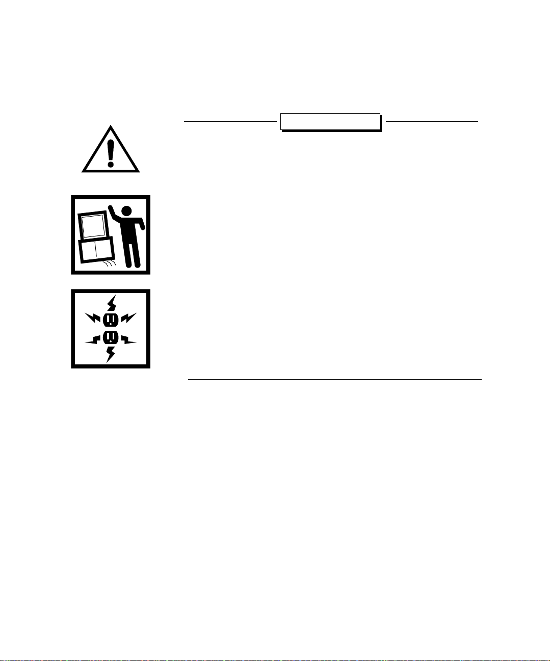
Warnings
❑ Heavy lifting required - To reduce the chance of personal
injury, you need at least two people to perform the lifting
required.
❑ In stall monitor as shown - Large video
monitors are very
heavy. Make sure that you mount the monitor as instructed.
❑ Avoid tipping - The Utility Cart
has been tested, and IEC 950
and UL-approved, for Polycom-approved 20- and 27-inch
monitors (22- and 29-inch monitors in Europe). If you use other
monitors, you must ensure that the Utility Cart cannot tip.
❑ Monitor Size - To reduce the chance of the cart tipping over, do
not use this cart with a monitor larger than 27-inch (29-inch in
Europe).
❑ Power cables and polarity - Use power cables and adapters
supplied by Polycom. Others may not have the correct polarity
or power ratings and may cause damage.
Note: You may need a flashlight while performing the
installation, depending on the lighting in the room.
3
Page 4

4
Page 5
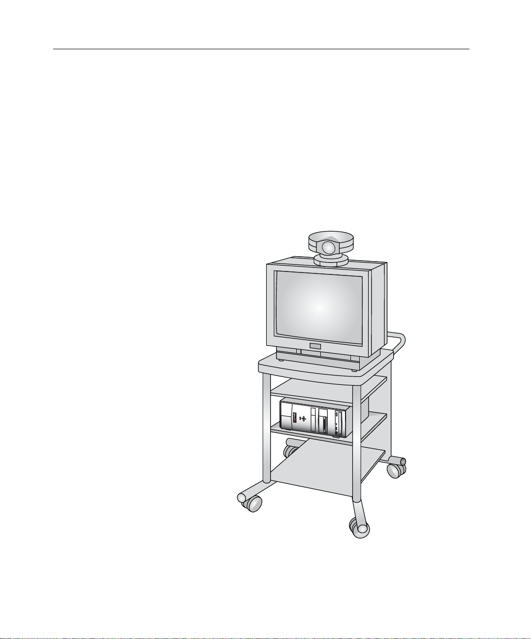
Installing a
Collaboration System
on the Utility Cart
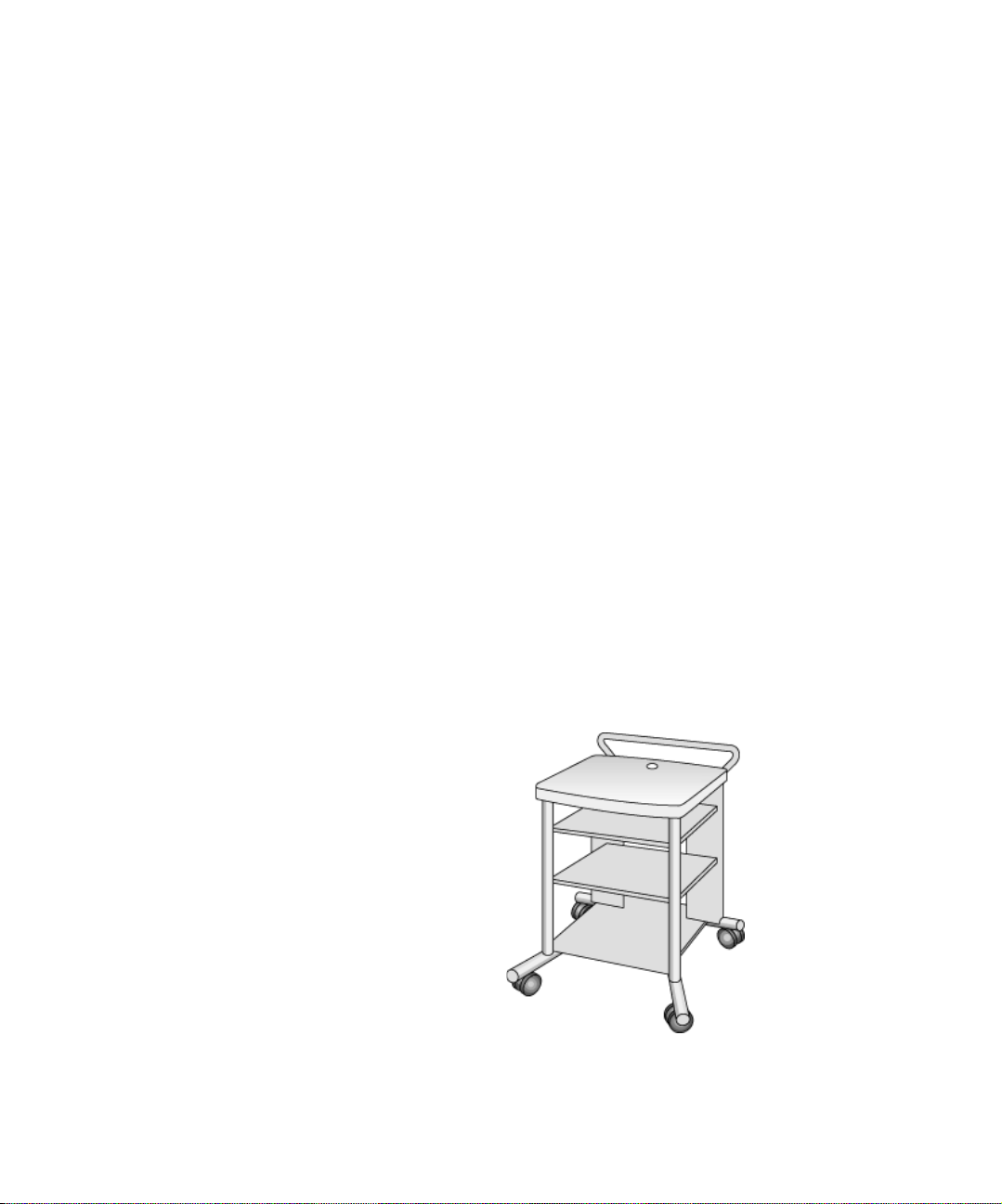
About this Booklet
This booklet provides instructions for installing a Polycom
collaboration system on a Utility Cart, including:
❑ Installing a comput er box or electronics module (page 6)
❑ Installing a 20- or 27-inch monitor (22- or 29-inch in Europe)
(page 9)
❑ Secu ring a 20- or 27-inch monitor (22- or 29-inch in Europe)
(page 11)
❑ Connecting the video cable (page 12)
❑ Connecting the audio cables (page 14)
❑ Connecting the power cables (page 17)
❑ Service and su pport (page 18)
5
Page 6
INSTALLING A COLLABORATION SYSTEM ON THE UTILITY CART
Installing the Computer Box or Electronics Module
Installing the iPower 900 Series Computer Box
The following sections describe how to install the computer box for
a iPower 900 Series system and the electronics module for a
Venue•2000™ system and a System 4000™ Series system.
To install the iPower 900 Series computer box:
1. Lock the wheels of the cart.
2. Place the computer box on the middle shelf.
6
Page 7

Installing the Computer Box or Electronics Module
Installing the Venue•2000 Electronics Module
To install the Venue•2000 electronics module:
1. Lock the wheels of the cart.
2. Place the electronics module on the middle shelf.
7
Page 8

INSTALLING A COLLABORATION SYSTEM ON THE UTILITY CART
a
b
c
Installing the System 4000 Series Electronics Module
To install the System 4000 Series electronics module:
1. Lock the wheels of the cart.
2. Pull and hold the shelf pins , at the front of the middle shelf, in
the out position.
3. Remove the middle shelf .
4. Place the electronics module on the bottom shelf in a vertical
position.
b
a
c
8
Page 9

Installing the Monitor
Installing the
Monitor
The following section describes how to install a Polycom-supplied
monitor onto the Utility Cart.
Note: If you are installing a second monitor for a iPower 900
Series system, be sure to install the camera onto the
NTSC or PAL monitor and not onto the VGA monitor. If
you are installing a second monitor for a System 4000
Series or Venue•2000 system, be sure to install the
camera onto the main monitor and not onto the graphics
monitor.
The required brackets and clamps are supplied with 20- or 27-inch
(22- or 29-inch in Europe) Polycom-supplied monitors. Use the
Polycom-supplied brackets to install these Polycom-suppl ied
monitors. The front bracket for the 27-inch (29-inch in Eur ope) VGA
monitor for the collaboration system is packaged separately, and it
should be used only for this Polycom-supplied monitor.
9
Page 10

INSTALLING A COLLABORATION SYSTEM ON THE UTILITY CART
c
To install a monitor:
1. Lock the wheels of the cart.
2. Position the front brackets so that the front corners of the
monitor will fit into the front brackets.
3. Install the screws through the brackets and into the top of the cart.
Tighten the screws.
4. With another person, place the monitor on the cart. Slide the
monitor toward the front brackets until the front corners of the
monitor fit into the brackets.
5. Position the rear clamp over the appropriate set of slots .
6. Install the screws from under the top of the cart and into the clamp.
Do not tighten the screws at this time.
a
b
b
c
c
a
a
a
10
Page 11

Securing the Monitor
a
b
c
Securing the
Monitor
To secure the monitor to the cart:
1. Slide the rear clamp forward.
2. Position the clamp into the indentation on the back of the
monitor.
3. Tighten the screws into the clamp.
b
a
c
11
Page 12

INSTALLING A COLLABORATION SYSTEM ON THE UTILITY CART
a
b
Connecting the Video Cable
Connecting the Video Cable to a iPower 900 Series System
This section describes how to connect the video cable to your
collaboration system.
If your monitor is different from the one in this illustration or if you
ordered a projector, refer to the documentation that you received
with the monitor or projector for information about connecting the
cables.
If you purchased an NTSC/PAL monitor, see the iPower 900 Series
Collaboration System Administrator’s Guide for information about
connecting the VGA cable in a dual-monitor system.
To connect the video cable to a iPower 900 Series system:
1. Connect one end of the VGA cable to the V GA connector on the
back of the monitor.
2. Thread the cable down through the hole on the back of the cart’s
top surface.
3. Connect the other end of the VGA cable to the VGA connector
on the back of the computer box.
4. Conceal any loo se cables b y placing them into the h ollow rear cart
legs.
a
o
8
1
A
8
4
2
1
7
4
ISDN
WAN
LAN
VCR
A/V
VGA
1
b
12
Page 13

Connecting the Video Cable
a
b
c
d
3
Connecting the Video Cable to a V enue•2000 or a System 4000
To connect the video cable to a Venue•2000 or a System 4000:
1. Plug one end of the video cable (yellow RCA plug) into the Video
Out connector ( for the System 4000 or for the Venue•2000)
on the back of the electronics module. For PAL systems, connect
the supplied SCART cable for both video and audio. (Audio/video
connector labels differ among monitors and may not appear as
shown.)
2. Thread the cable up through the hole on the back of the cart’s top
surface.
3. Plug the other end of the video cable into the Video In connector
( for the System 4000 or for the Venue• 2000) on the back of
the monitor.
4. Conceal any loo se cables b y placing them into the h ollow rear cart
legs.
System 4000
Venue•2000
c d
a
b
13
Page 14

INSTALLING A COLLABORATION SYSTEM ON THE UTILITY CART
a
aca
Connecting the Audio Cables
Connecting the Audio Cables to a iPower 900 Series System
This section describes how to connect the audio cables to your
system.
T o connect the audio cables to a iPower 900 Series sys tem when you
have a iPower 70 camera:
1. At the back of the collaboration system, plug the orange end of the
audio output cable into the orange Line Out connector on the
computer box.
2. Insert the red plug of the stereo adapter cable into the red
c
connector of the audio output cable .
3. On the same end of the stereo adapter cable , insert the white
plug into the white connector of the audio output cable .
4. Thread the stereo adapter cable up through the hole on the back
c
of the cart’s top surface.
5. Plug the remaining re d and white e nds of the st ereo adapte r cable
into the red and white connectors on the monitor.
d
b
8
d
o
8
1
A
8
4
2
1
7
4
ISDN
WAN
LAN
VCR
A/V
VGA
o
8
1
8
A
8
4
2
7
4
ISDN
WAN
A/V
b
14
c
a
Page 15

Connecting the Audio Cables
a
a
a
T o connect the audio cables to a iPower 900 Series sys tem when you
have a iPower 80 camera:
1. At the back of the collaboration system, plug the orange end of the
audio output cable into the orange Line Out connector on the
computer box.
b
2. Plug the single end of the black Y-adapter cable into the white
c
connector on the audio output cable .
3. Plug the end of the audio cable with the ferrite bead into one of
the connectors on the black Y-adapter cable .
4. Insert the red plug on the stereo adapter cable into the red
d
c
e
connector on the audio output cable .
5. On the same end of the stereo adapter cable , insert the white
plug into the remaining connector of the black Y-adapter cable .
6. Thread the stereo adapter cable and audio cable up through
e d
e
c
the hole on the back of the cart’s top surface.
7. Plug the remaining re d and white e nds of the st ereo adapte r cable
into the red and white connectors on the monitor.
8. Plug the other end of the audio cable into the white audio input
connector on the back of the iPower 80 camera.
f
f
8
d
e
o
8
1
A
8
4
2
1
7
4
ISDN
WAN
LAN
VCR
A/V
VGA
o
8
8
1
A
8
4
2
7
4
ISDN
WAN
A/V
b
a
c
15
Page 16

INSTALLING A COLLABORATION SYSTEM ON THE UTILITY CART
a
b
c
d
Connecting the Audio Cable to a V e nue•2000 or a System 4000
To connect the audio cable to a Venue•2000 or a System 4000:
1. Plug one end of the audio cable (white RCA plug) into the Audio
Out connector ( for the System 4000 or for the V enue•2000)
on the back of the electronics module. For PAL systems, the
SCART cable you connected in the previous section handles both
video and audio. (Audio/video labels differ among monitors and
may not appear as shown.)
2. Thread the cable up through the hole on the back of the cart’s top
surface.
3. Plug the other end of the audio cable into the mono or left chan nel
Audio In connector ( for the System 4000 or for the
Venue•2000) on the back of the monitor.
4. Conceal any loo se cables b y placing them into the h ollow rear cart
legs.
16
b
System 4000 Venue•2000
c d
a
b
Page 17

Connecting the Power Cables
a
b
Connecting the
Power Cables
To connect the power cables:
1. Thread the monitor power cable down through the hole on the
back of the cart’s top surface.
2. If you don’t have a power adapter cable, or if you have a iP ower 900
Series system, plug the monitor power cable directly into a wall
outlet and go to step 5.
3. If you have a power adapter cable connect it to the monitor
power cable.
4. Connect the power adapter cable to the power connector on the
electronics module.
5. Conceal any loo se cables b y placing them into the h ollow rear cart
legs.
6. If you are in the process of installing an entire collaboration
system, you may now return to y our collaboration system
installation instructions.
System 4000 Venue•2000
a
a
b
17
Page 18

INSTALLING A COLLABORATION SYSTEM ON THE UTILITY CART
Service and Support
For support or service, please contact your Polycom service
provider or call Polycom Technical Support. You can find phone
numbers for T echnical Support in your area at the Polycom web site,
www.polycom.com.
18
 Loading...