

Page 1

Installing the
™
iPower
70
Room Camera
Page 2

Copyright © 2000-2002: Polycom, Inc.
u
Polycom, Inc., 4750 Willow Road, Pleasanton, CA 94588
www.polycom.com
Polycomandthe Polycomlogoareregisteredtrademarksof Polycom,Inc. Concorde, Venue,and WorldCart
are trademarks of PictureTel Corporation.
Velcro is a registered trademark of Velcro USA, Inc.
All other company and product names are the trademarks or registeredtrademarks of their respective
owners.
The information contained in this document is subject to change without notice. Polycom assumes no
responsibilityfor technicalor editorial errors or omissionsthat may appear in this document or for the use of
this material. Nor does Polycom make any commitment to update the information contained in this
document. This document contains proprietary information which is protected by copyright. All rights
reserved. No part of this document may be photocopied or reproduced in any form without the prior written
consent of Polycom, Inc.
Edition: 3725-50453-001/A
Do you have any suggestionsor comments on the documentation yo
received? If so, pleasesend them by e-mail to iDesign@pictel.com.
Note: In this document, the term “monitor” i s used to refer to the NTSC or PALtelevision (TV) broadcast
receiver that is part of the collaboration system. These receivers are governed by different regulations than
computer monitors.
FCC Notice
This equipment has been tested and found to comply with the limits for a Class A digitaldevice, pursuant to
Part 15 of the FCC Rules. These limits are designed to provide reasonable protection against harmful
interference in a residential installation. This equipment generates, uses, and can radiate radio frequency
energy and, if not installed and used in accordancewith the instructions, may cause harmful interference to
radio communications. However, there is no guarantee that interferencewill not occur in a particular
installation. If this equipment does cause harmful interference to radioor television reception, which can be
determinedby turning the equipment off and on, the user is encouraged to try to correctthe interference by
one or more of the following measures:
-- Reorient or relocate the receiving antenna.
-- Increase the separation between the equipment and receiver.
-- Connect the equipment into an outlet on a circuit different from that to which the receiver is connected.
-- Consult the dealer or an experienced radio/TV technician for help.
The shielded cables provided with this equipment should be used to ensure compliance with the pertinent
RF emission limits governing this device. Where no cable is provided, shielded interconnection cables
should be used.
Notice to Canadian Users
This Class A digitalapparatus meets all requirements of the Canadian Interference-CausingEquipment
Regulations.
Cet appareil numérique de la classe A respecte toutes les dispositions du règlement sur les interférences
radioélectriquesdu Canada.
Page 3
Installing the
iPower 70
Room Camera
About this Booklet
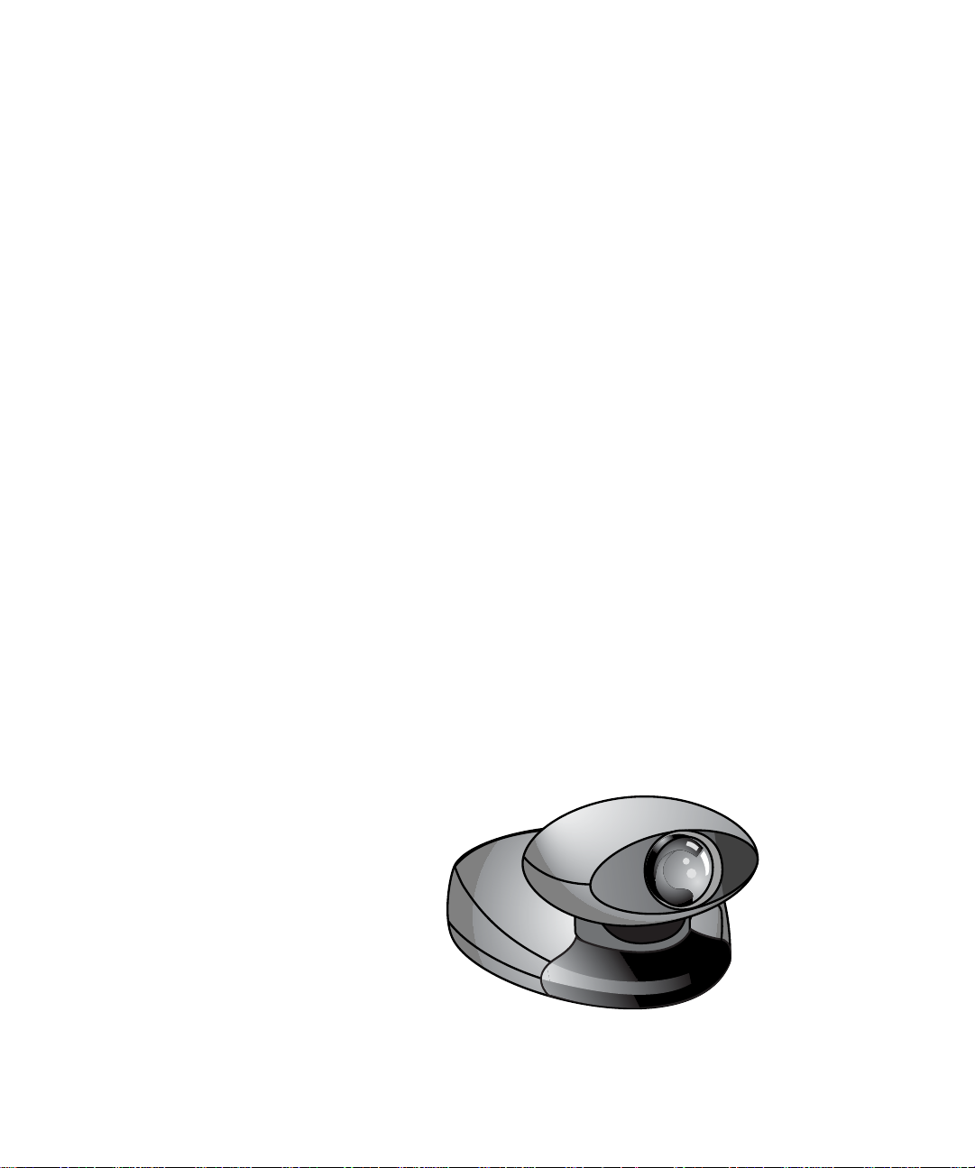
This booklet describes how to install the iPower® 70 room camera.
The iPower 70 is a pan-tilt-zoom (PTZ) camera that is used with a
iPower collaboration system as a main or an auxiliary camera.
This booklet contains information on:
❑ Before you install (page 4)
❑ Unpacking the box (page 5)
❑ Important note (page 6)
❑ Attaching the camera to a monitor (page 7)
❑ Connecting the camera cable to the collaboration
system (page 8)
❑ Connecting an additional power cable (page 9)
❑ Service and support (page 10)
❑ Specifications (page 10)
Refer to the collaboration system documentation for instructions on
how to use this camera.
3
Page 4

INSTALLING THE IPOWER 70 ROOM CAMERA
a
8
Before Installing
Before you begin this procedure, make sure you turn off
your collaboration system’s power switch.
To install this camera, you will need:
❑ The 8-pin camera cable (labeled with the icon on both
cable collars) that came with your collaboration system, the
WorldCart™, or the Premier Cart. (A camera cable is not
supplied with this camera.)
❑ One of the following systems:
• iPower 900 system, software version 1.0 or higher
• Concorde•4500™ system, software version 6.50 or higher
• Venue•2000™ system, software version 1.3.50 or higher
❑ A pencil
❑ A flashlight (optional)
Warning
a
4
Page 5

Unpacking the Box
Unpacking the
Box
To remove the camera from the box:
1. With two hands, grasp the outside edges of the packing material
and gently lift the unit from the box.
2. Carefully remove the camera from the packing material and place
it on a flat surface.
Caution
When lifting the iPower 70 camera, always lift the unit by its
base. Never lift the camera by its head.
Note: Before you continue with the installation of the camera,
please read the next section, “Important Note About
Moving the Camera.”
5
Page 6

INSTALLING THE IPOWER 70 ROOM CAMERA
Important Note AboutMovingthe Camera
The iPower 70 camera is designed to be controlled (moved) from the
collaboration system wireless keypad, the keyboard, or the remote
control. Be sure that your system is turned on before you move the
camera.
You should not manually move the camera from side to side (pan)
or up and down (tilt).
If you manually move the iPower 70 camera head, you may
experience unexpected camera pointing behavior when you use
camera presets.
To correct this condition, use the wireless keypad or the remote
control to do the following:
1. Press and hold the near-end right arrow button until the camera
rotatesasfarrightasitcan.
2. Press and hold the near-end left arrow button until the camera
rotates as far left as it can.
3. Press and hold the near-end up arrow button until the camera
moves up as far as it can.
4. Press and hold the near-end down arrow button until the camera
moves down as far as it can.
If the condition persists,
Power the collaboration system off and then on again.
6
Page 7
Attaching the Camera to a Monitor
Attaching the
Camera to a
Monitor
Note: If you are installing a second monitor for a iPower 900
system, be sure to install the iPower 70 camera on the
NTSC or PAL monitor and not on the VGA monitor. If
you are installing a second monitor for a Concorde•4500
or Venue•2000 system, be sure to install the iPower 70
camera on the main monitor and not on the graphics
monitor.
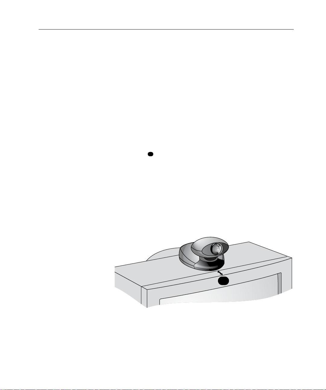
To attach the camera to the monitor:
1. Clean the top of the monitor using a dry cloth. This helps the
adhesive on the bottom of the Velcro
2. Without removing the backing from the adhesive strips, position
the camera on the top center of the monitor with the front base of
the camera within 0.75 inch (2 centimeters) of the front of the
monitor .
3. Witha pencil, markthe top of themonitor to indicate exactly where
you will be attaching the camera.
4. Remove the camera from the monitor and peel off the adhesive
backing from the Velcro strips.
5. Alignthe camera with the marks you made and firmly press it onto
the top of the monitor.
a
®
to adhere securely.
h
c
n
i
5
7
.
0
<
a
7
Page 8

INSTALLING THE IPOWER 70 ROOM CAMERA
a
8
b
8
c
8
8
Connecting the Camera Cable
Whenever you plug a cable into this camera, hold the
camera by its base, not by the camera head.
To connect the camera cable:
1. Plug the 8-pin camera cable (labeled with the icon on both
cable collars) into the 8-pin camera connector on the back of
the camera.
2. Locate the desired camera connector (labeled with the icon) on
the back of the collaboration system computer box or electronics
module . (Choose for main camera or for auxiliary
camera.)
3. Plug the other end of the camera cable into the desired camera
connector .
Caution
A
c
b
a
c
8
Page 9

Connecting an Additional Power Cable
a
Connecting an
Additional Power
Cable
Although the camera cable provides power to the iPower 70 camera,
if you are using a camera cable longer than 32.8 feet (10 meters), you
must use an additional power cable for the camera.
To connect an additional power cable:
1. Plug the additional power cable into the power connector on the
back of the camera .
2. Plug the other end of this cable into an appropriate power source.
If you are in the process of installing an entire collaboration system,
you may now return to your collaboration system installation
instructions.
If you are mounting this camera on a tripod, refer to the mounting
instructions included with your tripod mounting kit.
a
9
Page 10

INSTALLING THE IPOWER 70 ROOM CAMERA
Service and Support
Specifications
For support or service, please contact your Polycom service
provider or call Polycom Technical Support. You can find phone
numbers for Technical Support in your area at the Polycom web site,
www.polycom.com.
Physical Specifications
Dimensions: Length: 7.2 in. (18.3 cm)
Width: 7 in. (17.8 cm)
Height: 5.4 in. (13.7 cm )
Weight: 3.5 lb. (1.6 kg)
Operating and Nonoperating Environments
Temperature: Operating: 32° to 104° F (0° to 40° C)
Nonoperating: -40° to 158° F (-40° to 70° C)
Humidity: Operating: 15% to 75% (Noncondensing)
Nonoperating: 0% to 90% (Noncondensing)
10
Operating Specifications
Field of View: 66°
Pan Range: ±100°
Tilt Range: +15°/-30°
Zoom: 12x, autofocus
Resolution: 410,000 pixel, 0.25 in. (6 mm) CCD,
430 HTVL
Video Standard: NTSC or PAL
Power: +12V DC
 Loading...