

Page 1

Application Note
Polycom Installed
Voice Business
Group
September 2004
Polycom® Instant DesignerTM
Version 2.0
1
Page 2

Table of Contents
1. Introduction ................................................................................................................................... 3
2. What Polycom InstantDesigner does for you.......................................................................... 3
3. Getting Started with Polycom InstantDesigner....................................................................... 5
Step 1 – Select Inputs .........................................................................................7
Step 2 – Select Outputs.........................................................................................10
Step 3 – Sound Reinforcement Zones .....................................................................12
Step 4 – Create Zones ......................................................................................14
Step 5 – Set Zone Gains ........................................................................................15
Step 6 – Select Devices.........................................................................................17
Step 7 – Connect Inputs and Outputs ......................................................................18
Step 8 –Select Reports..........................................................................................19
Step 9 – Finish......................................................................................................23
4. InstantDesigner Results ............................................................................................................ 23
Input Settings ......................................................................................................24
Matrix Settings ....................................................................................................25
Macro Definitions.................................................................................................25
Logic mappings....................................................................................................28
5. Uploading to Vortex Devices .................................................................................................... 30
Setting Device ID’s ...............................................................................................31
Bussing the units..................................................................................................32
Connecting via RS232 ...........................................................................................32
6. Conclusion ................................................................................................................................... 35
7. Technical Support ...................................................................................................................... 36
Polycom Installed Voice Business group Contact Information.......................36
.
2
Page 3

1. Introduction
Polycom InstantDesigner™ release 2.0 is a revolutionary new way for
A/V integrators and consultants to quickly and accurately design audio and video
conferencing systems and sound reinforcement applications, with Polycom
Vortex
design software for Windows
guides the system designer through the steps required to create high performance
Vortex audio conferencing and sound reinforcement solutions.
The A/V integrator or consultant simply chooses the necessary inputs, outputs
(including the new Polycom VSX™ 7000 or VSX 8000 video codecs) and
optionally the sound reinforcement zones needed for the desired system, and
Polycom InstantDesigner automatically selects the appropriate Vortex devices
necessary to implement the system, maps the inputs and outputs to the devices,
and creates the Conference Composer design files required to implement the
design. It is easy to upload these design files to the Vortex devices to complete
the configuration. All of this can be done within a matter of minutes.
The Polycom InstantDesigner handles all the details of creating zone to zone
gains for sound reinforcement, configuring the acoustic echo cancellers,
interfacing to common audio and video equipment, bussing between devices,
configuring presets, creating volume control macros, and preconfiguring logic ports
for push to talk microphones.
®
audio and video products. A new addition to our Conference Composer™
®
, the patent pending Polycom InstantDesigner
Polycom InstantDesigner will change the way audio and video conferencing
systems are designed. The immediate benefits of using Polycom InstantDesigner
include
• Dramatically reduced design time – from hours to minutes (or less) which
means more profit to the A/V designer
• More consistent A/V designs – there is now a “Vortex expert” included with
every product purchased
• More satisfied end-users due to quicker and better installations
• Reduced learning curve for A/V specialists to confidently design larger
systems for any type of application.
Read more to learn how Polycom InstantDesigner will change the way you design
audio and video conferencing systems.
2. What Polycom InstantDesigner does for you
Polycom InstantDesigner release 2.0 encapsulates the design expertise of the
Vortex engineering team and the experience of thousands of successful audio and
video conferencing installations. We have learned both the easy way and the hard
way what works and how to best use the Vortex products. By making Polycom
InstantDesigner available to you, the A/V specialist, we want to make your job
easier and allow you to spend more time doing the things that can help your
3
Page 4

design and integration firm be more profitable. To give you an idea of how much
the design process can be accelerated, below is a partial list of what Polycom
InstantDesigner will do for you. With just a few mouse clicks, Polycom
InstantDesigner will automatically:
• Select the Vortex equipment necessary to implement the system
• Map the input and output equipment to Vortex inputs and outputs (e.g.,
lectern microphone is input 1 on Vortex EF2280:00)
• Set the input and output gains in the Vortex required to interface to the
selected input and output equipment (e.g., most video codecs typically
require 10dB of input gain, and 5dB of output attenuation)
• Configure the automatic microphone mixer for linked operation for larger
systems
• Create all the matrix crosspoints necessary to use the resulting system
(e.g., local audio is sent to the remote site and remote audio is played back
into the room)
• Create loudspeaker zones for sound reinforcement and allow you to specify
the microphones that are part of that zone and reinforced into other zones
• Make it easy to modify the zone to zone crosspoint gains needed for sound
reinforcement across zones
• Configure all the bussing across linked devices (e.g., local microphones are
automatically sent to all devices), including sound reinforcement zone gains
• Configure the acoustic echo cancellation (e.g., the echo canceller reference
is configured and all linked devices are configured to use the bus reference)
• Customize the text labels for all inputs and outputs including the bussing
signals
• Save the settings to Preset 16 and set the power-on preset on all devices
• Create macros for muting, unmuting, and volume control
• Create logic assignments making it easy to connect push-to-talk
microphones or other hardwired control systems
• Create a project summary of the wiring connections and necessary
equipment
• Create formatted PDF reports of your system configurations
• Create a zone to zone sound reinforcement summary report
• Create a signal routing report so you can see how the signals are routed
and bussed to create the appropriate sound reinforcement zones
• Create DXF drawings of your designs
• Upload the Conference Composer project to your Vortex devices
4
Page 5

The list keeps growing and growing. Imagine what you can do with Vortex
products now – perform more conference designs with your current team, create
new conferencing applications, build more expertise within your team, etc. If you
haven’t tried the Vortex products – you can’t afford not to.
Sit back, grab a cup of coffee, and learn how we are trying to make your job
easier.
3. Getting Started with Polycom InstantDesigner
To use Polycom InstantDesigner simply start Conference Composer. You will be
presented with the screen shown in Figure 1.
Figure 1. Conference Composer startup screen.
From here there are three choices
1. Autoscan for Devices retrieves the settings from the Vortex devices and
puts them into Conference Composer– this requires that you be connected
to a Vortex via an RS232 connection.
2. Create Project with Polycom InstantDesigner begins the instant design
process.
3. Open Existing Project opens a previously designed Vortex project.
Selecting Create Project with Polycom InstantDesigner will start the Polycom
InstantDesigner process and bring you to the screen in Figure 2. If you are
already running Conference Composer you may start Polycom InstantDesigner by
5
Page 6

selecting Polycom InstantDesigner from the Project menu or using the keyboard
shortcut of Ctrl-i.
Please note that at any step in the Polycom InstantDesigner process, the Polycom
InstantDesigner information can be saved to disk by clicking on the floppy disk
icon. This is a useful and recommended step in case changes need to be made to
the configurations within Polycom InstantDesigner after the initial design process
is complete.
Clicking the help icon will provide a step by step instruction guide for using the
InstantDesigner software.
Figure 2. Polycom InstantDesigner welcome screen.
From a high level perspective as shown in Figure 3 there are two paths through
the InstantDesigner software, depending on whether sound reinforcement is
required.
6
Page 7

Select
Inputs
Step 1
Step 4
Step 5
No Sound Reinforcement
Select
Devices
Connect Inputs and
Outputs
Use Sound
Reinforcement
Use Sound
Reinforcement
Define Zones
Set Zone
Reinforcement Levels
Connect Inputs and
Select
Outputs
?
Select
Devices
Outputs
Step 2
Step 3
Step 4
Step 5
Step 6
Step 7
Step 6
Create Conference
Composer Project
Create Zone Reports
Create Conference
Composer Project
Step 8
Step 9
Figure 3. The steps of using the InstantDesigner software – either 6 steps or 9 steps are
required depending on whether sound reinforcement is required for the design.
As we shall see, there are either 6 steps (without sound reinforcement) or 9 steps
required to design the complete audio and video conferencing system.
Click Next to start the wizardry of the Polycom InstantDesigner.
Step 1 – Select Inputs
The first step of Polycom InstantDesigner is to select the types and quantities of
inputs that are required in the audio design. The types of inputs that can be
selected include:
• Microphones – including table, ceiling, lectern, and wireless microphones
7
Page 8
• Program audio – including both stereo and monaural consumer and
professional playback devices such as DVD players and VCRs
• SoundStation VTX 1000™ for wideband telephony
• PSTN Telephone line interfaces for narrowband telephony interfaces
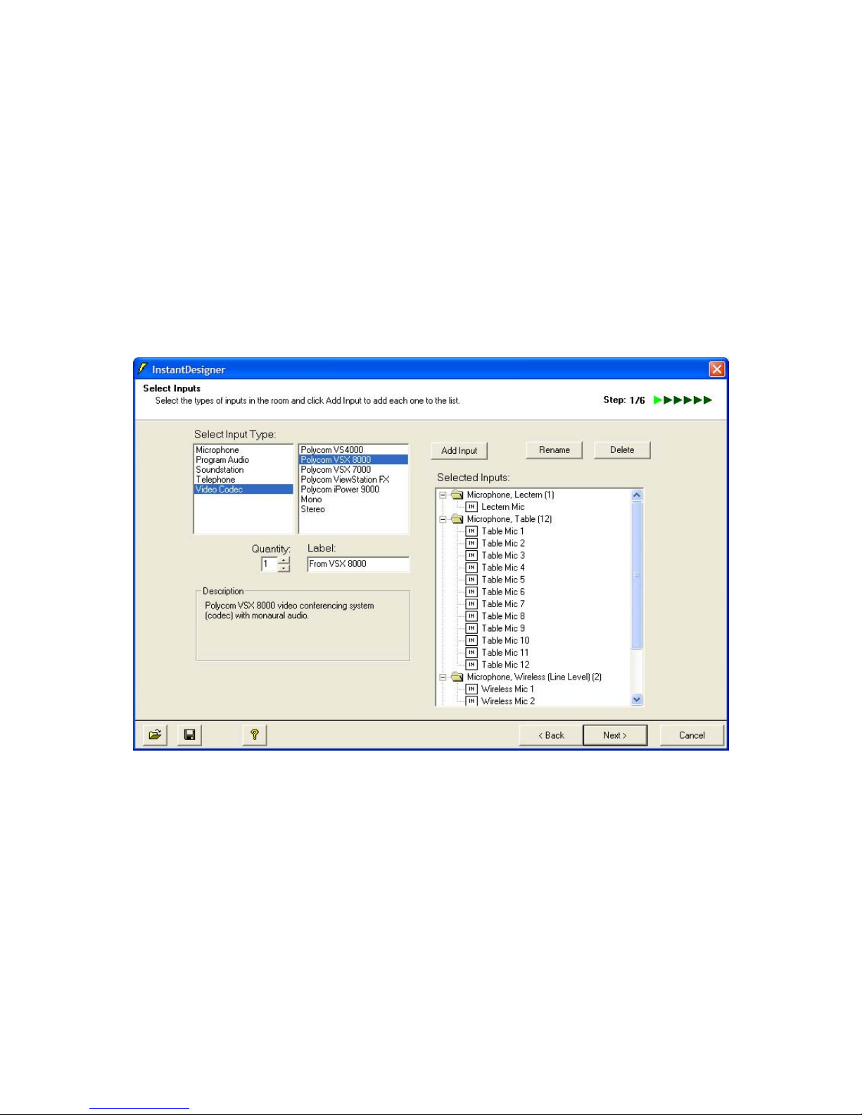
• Video codecs – including Polycom VSX™ 7000, VSX 8000, ViewStation
®,
and iPower™
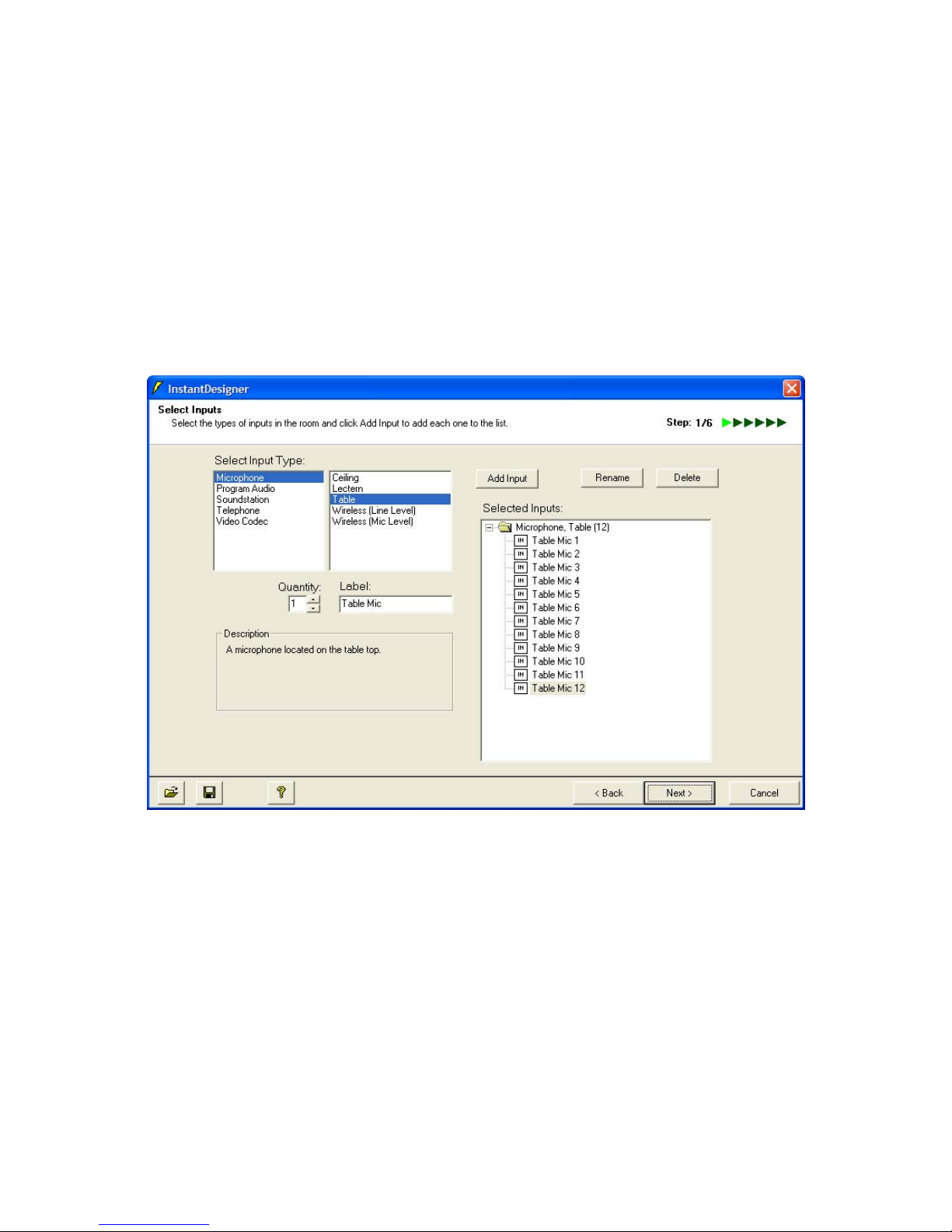
Select the types of input, such as Microphone and Table, choose the quantity,
adjust the text label, and then click Add Input. This will add the selected items to
the Selected Inputs text box as shown in Figure 4.
Figure 4. Polycom InstantDesigner Step 1 – Select Inputs.
In this application note, we will design a system that includes 12 table
microphones, a lectern microphone, two wireless microphones, a VSX 8000 video
codec, an analog phone line, stereo program audio, a monaural recorder, and an
assistive listening device. This room might look like the room in Figure 5.
8
Page 9

Zone 1 Zone 2 Zone 3
Figure 5. A typical 3 zone room including 12 tabletop microphones with imaginary lines showing the different loudspeaker zones.
9
Page 10
Please note that at any time during the Polycom InstantDesigner process you may
save your design to an InstantDesigner template file (*.idt) by selecting the floppy
icon on the lower left of the screen. The design specifications that you have
created up to that point can be restored from a saved file by selecting the folder
icon on the lower left of the screen. These Conference Composer template files
are different from the files that Conference Composer creates and can be used to
share your design intent with your team, subcontractors, etc. before the complete
Conference Composer project file is created.
After the input selections have been made, select Next to go to Step 2 – Select
Outputs.
Figure 6. Sample input selection with 12 table microphones, a lectern microphone, 2 wireless
microphones, stereo program audio, telephone interface, and a Polycom VSX 8000 video codec.
Step 2 – Select Outputs
The second step of Polycom InstantDesigner is to select the outputs that will be
used. By default, some outputs will already be selected, such as a telephony
output and a video codec output, if their respective inputs have been selected.
This automatic selection is shown in Figure 7.
The types of outputs that may be added to the system include:
• Assistive listening
10
Page 11
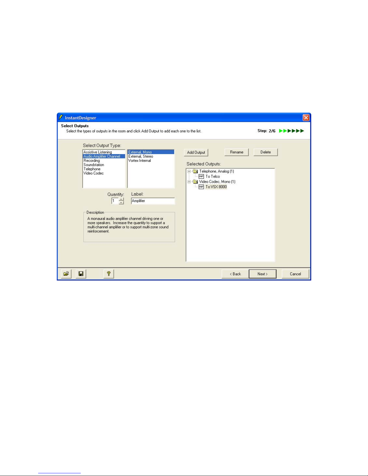
• Audio amplifier channels – including monaural and stereo amplifiers
• Recording outputs – including monaural and stereo outputs
• SoundStation VTX 1000
• PSTN Telephone outputs
• Video codecs – including Polycom VSX, ViewStation, and iPower
Figure 7. Polycom InstantDesigner Step 2 -- Select Outputs
Audio amplifier channels are the monaural audio channels that are used to drive
loudspeaker zones in the room. Multi-channel amplifiers are often used in practice
and can be specified by increasing the quantity field once the audio amplifier
channel has been selected. If stereo program audio is used with the system, a
stereo amplifier should be selected, even if the stereo pair will built from two
channels of a multi-channel amplifier. This will simplify the automatic sound
reinforcement routing in the next step. In the current example three zone
amplifiers (labeled Front Speakers, Mid Speakers, and Rear Speakers) have been
selected in addition to a stereo amplifier for the stereo program audio.
As with the input selection, select the type and quantity of outputs that are needed
for the design. In the design example in this application note the output selection
will look like Figure 8.
After the output selections have been made, click Next to go to Step 3 – Sound
Reinforcement Zones.
11
Page 12

Figure 8. Sample output selection with a telephone output, video codec output, stereo audio amplifier
for program audio, three mono amplifiers, mono recording output, and a mono assistive listening
output.
Step 3 – Sound Reinforcement Zones
The next step for InstantDesigner is to determine whether to use sound
reinforcement zones as shown in Figure 9. Sound reinforcement allows the
designer to create loudspeaker zones, place microphones into these zones, and
control the amount of reinforcement of the microphones into neighboring
loudspeaker zones. Microphones that are placed in a loudspeaker zone are NOT
reinforced into the same loudspeaker zone – the microphones will only be
reinforced into other loudspeaker zones.
Answering No to question posed in Step 3 will move the designer to the next step
in the process, Select Devices. This step is described in the section entitled Step 6
– Select Devices.
Answering Yes to the question posed in Step 3 will show the screen in Figure 10,
emphasizing that microphones from one loudspeaker zone will be reinforced into
other loudspeaker zones with the blue microphone audio and green microphone
audio indicating different loudspeaker zones. Answering Yes also increases the
number of steps in the process from 6 to 9 as additional information is required to
properly configure the loudspeaker zones (see Figure 3).
12
Page 13

Figure 9. Step 3 where the designer does NOT want to use sound reinforcement.
Figure 10. Step 3 where the designer does want to use sound reinforcement. Notice the microphone
and loudspeaker audio in the two zones.
13
Page 14

Figure 11. Default sound reinforcement zone definitions.
Once the designer has decided whether to use zoned sound reinforcement, the
next step, if reinforcement is required, will be to define the zones as shown in
Figure 11.
Step 4 – Create Zones
Reviewing the screen in Figure 11, notice that three amplifier zones were created,
matching the selection of three amplifier channels selected in Step 2. The zones
are labeled Zone 1, Zone 2, and Zone 3 and they include the amplifier channels:
Front Speakers, Mid Speakers, and Rear Speakers, respectively, corresponding to
the amplifier channel names selected previously. Please note that the stereo
amplifier channels are not included as zone amplifiers in the sound reinforcement
steps of Polycom InstantDesigner.
The microphones were automatically evenly divided into the loudspeaker zones
with 4 microphones being placed into each loudspeaker zone. If the design
requirements differ from this default, the microphones may be easily moved to the
desired zones by selecting Manually Define Sound Reinforcement Zones and
dragging the microphones into the appropriate zone.
A presenter zone was automatically created because presenter style microphones
(lectern and wireless microphones) were selected in Step 1. The presenter zone
has no amplifier associated with it, but includes the three microphones (lectern,
14
Page 15

wireless microphone 1 and wireless microphone 2) that are used for reinforcement
into the entire room through the three amplifier zones for this example. If the
design requires that the presenter microphones be physically located in a
loudspeaker zone (due to room layout constraints or design preference), it is
possible to either add these microphones to an existing zone (Zone 1, 2, or 3 as
shown in Figure 12). Please note if the presenter microphones are moved into
Zone 1, these microphones will not be reinforced into Zone 1 but will be reinforced
into Zone 2 and Zone 3 with the reinforcement levels to be specified in the next
step.
Figure 12. The presenter microphones (lectern, wireless 1, and wireless 2) were moved to Zone 1 in
this figure.
Continuing this example, we will leave the presenter microphones in the presenter
zone and the other microphones in their respective zones as shown in Figure 11.
The next step is to specify the amount of the sound reinforcement required across
zones.
Step 5 – Set Zone Gains
Step 5 (when using zoned reinforcement) allows the designer to specify the levels
used to reinforce microphones into different loudspeaker zones. As shown in
Figure 13, the microphone zones on the left include the microphone definitions for
each zone – holding the mouse over the zone name will show which microphones
are in that zone. The amplifier zones on the top represent the loudspeaker zones
15
Page 16

– holding the mouse over the zone name on the top will show which amplifier is in
that zone.
By default each zone of microphones is mapped to the remaining loudspeaker
zones with a gain of -30dB. In this zone matrix view, the columns are summed to
create the outputs to the loudspeaker amplifier zones. For example, in Figure 13,
the reinforcement for Zone 1 is the sum of the microphones in Zone 2 (attenuated
by 30dB) the microphones from Zone 3 (attenuated by 30dB), and the presenter
microphones (also attenuated by 30dB). Please note that the microphones from
Zone 1 are NOT included in the output for Zone 1 and consequently the crosspoint
is grayed out to minimize the occurrence of acoustic feedback from a microphone
in a zone being reinforced into the same zone.
Figure 13. Default Zone gain matrix for this example.
The reinforcement levels from microphones to loudspeaker zones can be adjusted
by left clicking on the appropriate crosspoint and adjusting the slider that appears
on the left. Figure 14 shows setting the Zone 2 to Zone 1 reinforcement level to 18dB.
The amount of reinforcement required will depend on the room design, the
physical separation between zones, and the style and placement of microphones
and loudspeakers. A conservative reinforcement level is recommended as a
starting point to minimize the incidence of acoustic feedback within the room.
After configuring the devices with the specified room reinforcement level, it is
possible to change the reinforcement levels either in the Vortex devices by
16
Page 17

manually adjusting crosspoint gains, or by re-running the InstantDesigner and
adjusting the zone matrix and re-uploading the configuration file to the Vortex
devices.
Figure 14. The reinforcement level for the microphones in Zone 2 to loudspeakers in Zone 1
is set to -18dB.
In Figure 14, the reinforcement level between adjacent zones was adjusted to
-18dB and the reinforcement level between zones two zones apart was -12dB.
These zone gains will be used to create the routing and mapping through the
Vortex matrix and bus matrices.
After the reinforcement levels have been specified, the next step is to determine
the equipment required to implement the design. If sound reinforcement was
used, this will be step 6; if sound reinforcement was not used, the next step will be
step 4.
Step 6 – Select Devices
The next step for InstantDesigner is to select the Vortex devices that are required
to implement the system. The two criteria for automatically selecting these
devices are minimum cost or minimum rack space. Minimum cost selects the
equipment with the lowest list price while minimum rack space selects the
equipment that requires the fewest rack spaces. The default method is to choose
the equipment that has the minimum cost, but there are times where the minimum
rack space selection may be preferable. For many systems, but not all, the two
results are the same.
17
Page 18

There is also an option for manually selecting the equipment in case there is
specific equipment to be used in the installation. To use this option, select Manual
and then select Add Device to add devices to the selection. To delete devices,
select the device and click Delete Device. Please note that if you manually select
devices and then select Automatically Select Devices, your manual selections will
be overwritten with the automatic selection.
In this example, the automatic method of selecting devices was used and the
resulting equipment list consists of 2 Vortex EF2280’s and 1 Vortex EF2201 as
shown in Figure 15. In addition to the device selection, this window shows the
number of unused microphones, line inputs, line outputs, and telephone
connections that are presently unused with the equipment selection. In our
example, there is 1 microphone input, 6 line level inputs and 16 line level outputs
available.
Select Next to go to Step 4 – Connecting Inputs and Outputs.
Figure 15. Polycom InstantDesigner Step 6 -- Selecting the devices shows the automatic equipment
selection.
Step 7 – Connect Inputs and Outputs
The next step for Polycom InstantDesigner is to determine how to connect the
inputs and outputs to the actual device inputs and outputs. This process is done
automatically, but the signals can be manually moved around – when not using
sound reinforcement – by selecting Manually Connect Inputs and Outputs and
dragging the appropriate input or output to the desired location.
18
Page 19

After mapping the inputs and outputs to the device inputs and outputs, Select Next
to go to Step 8 – Reports.
Figure 16. Polycom InstantDesigner Step 7 -- Connect Inputs and Outputs
Step 8 –Select Reports
When using sound reinforcement, there are two new reports that are available for
the system designer – a zone matrix report, and a signal routing report. These
report options are shown in Figure 17.
19
Page 20

Figure 17. The zone reports that can be generated when using sound reinforcement.
The zone matrix report is a spreadsheet that summarizes the zone reinforcement
gains for the inputs and outputs. An example of this report showing the zones,
zone inputs and outputs, zone reinforcement crosspoints, and the devices that
inputs are connected to is shown in Table 1. The zone matrix report is created at
Step 9 at the same time the complete Conference Composer design file is created.
20
Page 21

Table 1. The zone matrix report for the design example.
Device EF2280:00 EF2280:01 EF2280:00
Output
Zone
Zone
Zone 1 Table Mic 1
Mic Device
EF2280:00
Table Mic 2
Table Mic 3
Table Mic 4
EF2280:00
EF2280:00
EF2280:00
112
Zone 1 Zone 2 Zone 3
--
--
--
--
-18 -12
-18 -12
-18 -12
-18 -12
Zone 2 Table Mic 5
Table Mic 6
Table Mic 7
Table Mic 8
Zone 3 Table Mic 9
Table Mic 10
Table Mic 11
Table Mic 12
Presenter Lectern Mic
Wireless Mic 1
Wireless Mic 2
EF2280:01 -18
EF2280:01 -18
EF2280:01 -18
EF2280:01 -18
EF2280:00 -12 -18
EF2280:00 -12 -18
EF2280:00 -12 -18
EF2280:00 -12 -18
EF2280:01 -18 -12 -12
EF2280:01 -18 -12 -12
EF2280:01 -18 -12 -12
--
--
--
--
-18
-18
-18
-18
--
--
--
--
In addition to the zone matrix report, Table 2 shows a part of the zone routing
spreadsheet illustrating how the Zone 1 loudspeaker output is created from
microphone signals, codec, and phone add audio.
In this example, the Zone 1 output is built from the Zone 3 microphones
(attenuated 12dB), the telephone from the EF2201, the Zone 2 microphones
(attenuated by 18dB), the presenter microphones (attenuated by 8dB), and the
VSX 8000 video codec audio.
The report in Table 2 also shows the details on how the signals are bussed – for
instance the presenter microphones are transmitted on the X bus from EF2280:01
and input to EF2280:00 on input XB1, attenuated by 18dB and then fed into the
main matrix of EF2280:00 and summed together with the other signals to create
the Zone 1 loudspeaker output.
21
Page 22

Table 2. An example of the zone routing report showing how Zone 1 is built from the presenter microphones, Zone 3 microphones, Zone 2
microphones, the remote telephone audio, and the remote video audio.
Zone : Amplifier Gain Signal Gain Signal Gain Signal Gain Signal
Zone 1 : Front Speakers (EF2280:00 Output 1)
-12
Zone 3 : Table Mic 9 (EF2280:00 Input 5)
-12
Zone 3 : Table Mic 10 (EF2280:00 Input 6)
-12
Zone 3 : Table Mic 11 (EF2280:00 Input 7)
-12
Zone 3 : Table Mic 12 (EF2280:00 Input 8)
0 SubMix Phones (EF2280:00 Input PM0)
0 Bus Phones (EF2280:00 Input PB0)
0 Bus Phones (EF2201:00 Output P)
0
From Telco (EF2201:00 Input T)
0 - (EF2280:00 Input PB1)
0 - (EF2280:00 Input PB2)
0 - (EF2280:00 Input PB3)
0 - (EF2280:00 Input PB4)
0 - (EF2280:00 Input PB5)
0 - (EF2280:00 Input PB6)
0 - (EF2280:00 Input PB7)
0 Zone 1 (EF2280:00 Input WM1)
-18 Zone 2 (EF2280:00 Input WB1)
0 Zone 2 (EF2280:01 Output W)
0
Zone 2 : Table Mic 5 (EF2280:01 I
n
0 Zone 2 : Table Mic 6 (EF2280:01 I
n
0
Zone 2 : Table Mic 7 (EF2280:01 I
n
0
Zone 2 : Table Mic 8 (EF2280:01 I
n
0 Zone 1 (EF2280:00 Input XM1)
-18 Presenter (EF2280:00 Input XB1)
0 Presenter (EF2280:01 Output X)
0
Presenter : Lectern Mic (EF2280:
0
0
Presenter : Wireless Mic 1 (EF228
0
0
Presenter : Wireless Mic 2 (EF228
0
0 SubMix Mono (EF2280:00 Input YM1)
0 Bus Mono (EF2280:00 Input YB1)
0 Bus Mono (EF2280:01 Output Y)
0
From VSX 8000 (EF2280:01 Input
A
22
Page 23

These new sound reinforcement reports complement the existing summary reports
and cad drawings that are created automatically by Conference Composer.
Step 9 – Finish
The final step for Polycom InstantDesigner shows the equipment list and signal
connections for your review. The equipment and signal connection summary can
be saved as a text file by clicking the Export Summary button. Device inputs and
outputs that are not used are not listed in the design summary.
To create the Conference Composer design file, click Next.
Figure 18. Polycom InstantDesigner Step 9 of 9 – Finishing a design with sound reinforcement.
4. InstantDesigner Results
The final result from the Polycom InstantDesigner is the Conference Composer
configuration file (*.ccp) that can be uploaded to the Vortex devices. The result of
using Polycom InstantDesigner with our design example is shown in Figure 19.
The A/V specialist can simply set the device ID’s of the Vortex devices to match
the device ID’s in the project, connect the required Vortex devices together, and
upload the results to the Vortex devices for final system testing and configuration.
This process is described in Section 5.
23
Page 24

The Conference Composer file contains the appropriate Vortex configuration for all
input, automixer, matrix mixer, output, bussing, macro, and logic settings as
described next.
Figure 19. Polycom InstantDesigner automatically generates the Conference Composer project
file that can be uploaded to Vortex devices.
Input Settings
The Polycom InstantDesigner configures table top microphones to have phantom
power enabled and to have 48dB of gain (mic mode provides 33dB of gain, and
then an additional 15dB of gain is applied). Ceiling microphones are configured to
have 58dB of gain and to have phantom power enabled.
24
Page 25

Wireless microphones do not use phantom power and will have an input gain that
depends on whether they are mic level mode or line level mode.
Video codecs and other consumer-level audio equipment are automatically
configured to have 10dB of gain on the input and -10dB of gain on the output to
match the 0dBu nominal levels of the Vortex devices. The VSX 8000 codec
interfaces at 0dB input and 0dB output gains due to the use of professional signal
levels and balanced audio connections on the VSX 8000.
Matrix Settings
Polycom InstantDesigner automatically configures the matrix, the zone to zone
reinforcement gains, the acoustic echo canceller references, and the bussing
(when multiple Vortex devices are required). All microphone audio is sent to the
remote participants (video codec, telephony, etc.), and remote audio is sent to the
loudspeaker, and program audio is sent to left and right program audio
loudspeakers. The text labels that were initially selected are automatically used as
the text labels within Conference Composer.
Microphones are bussed appropriately to ensure they are available to all
connected devices and at the appropriate reinforcement level.
Macro Definitions
Polycom InstantDesigner will configure each Vortex device with a set of macros
that can be used for volume control of microphones, program audio, muting and
unmuting microphones, amplifier volume control, etc. In our example, the macros
are shown in Figure 20, and the complete set of macros that are created for the
Vortex EF2280 in this example is shown in Table 3.
25
Page 26

Figure 20. The macro tab in this example shows the set of macros that were automatically created for
Vortex EF2280 (device ID 00) by Polycom InstantDesigner
26
Page 27

Table 3. The macros that are created automatically for an EF2280 by the Polycom InstantDesigner.
Macro Name Description
Mics Up Increases the volume of the microphones by 1dB
Mics Down Decreases the volume of the microphones by 1dB
Mics Mute Mutes the microphones in all linked Vortex devices
Mics UnMute UnMutes the microphones in all linked Vortex devices
Program Up Increases the program audio inputs by 1dB
Program Down Decreases the program audio by 1dB
From Codec Up
From Codec Down
Amplifier Up
Amplifier Down
Amplifier Mute
Amplifier UnMute
Increases the incoming codec signal by 1dB
Decreases the incoming codec signal by 1dB
Increases the program audio amplifier volume by 1dB
Decreases the program audio amplifier volume by 1dB
Mutes the outputs of the program audio to the amplifier
UnMutes the outputs of the program audio to the amplifier
These macros may be executed via RS232 commands to the Vortex devices as
outlined in the command set document and in the Conference Composer Help file.
Typically, a control system such as an AMX
®
or Crestron® would send these
commands to execute the appropriate function. To mute the microphones in this
example, the control system would send the command
F00MACROX2↵
where ↵ is a carriage return.
This would execute Macro 2 in the Vortex EF2280 with device ID 00. Macro 2 in
this case would cause the microphones on both Vortex EF2280’s (ID’s 00 and 01)
to be muted.
To unmute the microphones, the control system would send the command
F00MACROX3↵
The way the macros are configured for the Vortex devices, it does not matter
whether macros 2 and 3 are executed on the Vortex EF2280 of device ID 00 or
device ID 01 – either device will mute or unmute the microphones on the other
device through the use of the BROADA command to forward the command to the
other linked Vortex devices.
27
Page 28

Logic mappings
In addition to creating the macros for many common functions, InstantDesigner
also creates logic input pin mappings that can execute these macros through
simple contact closures, such as the contacts from push-to-talk microphones or
toggle and push button switches that are wired to the logic ports on the devices.
In our example, the logic mappings are shown in Figure 21. Each microphone
input has an associated pin on the Vortex logic input port on the rear panel. In this
example, the table microphone 1 mute contact closure is wired to pin 1 with the
ground pin of the push-to-talk microphone connected to pin 25 of the logic input
connector. In this example, when input 1 is shorted to ground (pin 25), Macro 3
will be executed –unmuting the microphones. When input 1 is opened, Macro 2
will be executed – muting the microphones.
While muting microphones with push-to-talk microphones is important, knowing
the status of whether the microphones are muted is even more important.
InstantDesigner takes care of this for the A/V specialist by creating default logic
output status mappings that can be used to drive the LED on the microphone so
that the LED is “on” when the microphone is active (unmuted) and the LED is “off”
when the microphone is inactive (muted). The default mappings are shown in
Figure 22. Notice there are additional logic output mappings that can be used to
show the gating status of a microphone – if the microphone is gated “on”, the LED
could be turned on for that microphone.
For more information on how to wire push-to-talk microphones to the Vortex, open
the help file within Conference Composer and review the Application Notes section
for a detailed explanation.
28
Page 29

Figure 21. The default logic input definitions showing the microphone inputs and their associated
macros for muting and unmuting.
29
Page 30

Figure 22. The default logic output definitions showing the microphone inputs and their associated
macros for illuminating the LEDs on the microphones according to muting and gating status.
5. Uploading to Vortex Devices
Once Polycom InstantDesigner has created the complete Vortex configuration for
the desired audio design, the next step is to upload the settings to the Vortex
devices. When the system design requires more than one Vortex device, the first
step is to set the device ID’s of the devices to the settings that Polycom
InstantDesigner designates for those particular devices. The device ID settings
can be found on the left panel of the Conference Composer screen where each
device in the project is listed with its device ID. In this example, there will be a
30
Page 31

Vortex EF2201 at device ID 00, a Vortex EF2280 at device ID 00*, and a Vortex
EF2280 at device ID 01, as shown in Figure 23.
*Vortex EF2280 and Vortex EF2201 units can share a device ID, allowing you to
have up to 8 each of these devices in a linked system.
Figure 23. The device ID's of the Vortex equipment are highlighted in red.
Setting Device ID’s
The device ID’s can be configured from the front panel of each device. In this
example we simply need to set the device ID on one of the Vortex EF2280’s to 01.
31
Page 32

To do this, apply power to the Vortex EF2280 that needs to have its device ID
changed. Enter the front panel System Settings by pressing the “up” button on the
front panel until System Settings is shown on the LCD. Press the “enter” button to
enter this menu tree. Continue pressing the “up” button until the device ID of the
device is shown. By default, each device is set to Device ID 00. Press “enter” on
the front panel to make the device ID number flash. Press the “up” button to
increase the device ID to 01. Press “enter” again to make the device ID stop
flashing and to save the new device ID. The device ID has now been set to device
ID 01.
Bussing the units
Once the device ID’s are set properly, the devices can be bussed together using
the supplied EF bus cable. Each device’s EF bus out connector should be
connected to the next device’s EF bus in connector. Please note that the last
device should NOT be connected back to the first device and that bus terminators
are not required with Polycom Vortex devices.
Once the devices are connected, the remaining devices may be powered on.
After several seconds, the devices will boot up and display the default LCD menu.
If a Device ID conflict message is shown on the LCD, it means that more than one
of the same type of Vortex product has the same device ID. Please double-check
the device ID’s and recycle power on the devices.
Connecting via RS232
Finally, once the devices are bussed together, the Conference Composer design
file may be uploaded to the linked devices. Connect an RS232 cable from your
PC to the RS232 port on one of the linked Vortex devices. To specify which
RS232 port will be used, left click on the device chain, as shown in Figure 24, and
select the appropriate transport (such as Com 1, Com 2, etc.) as shown in Figure
25.
32
Page 33

Figure 24. To set the appropriate RS232 port, left click the device chain and select the
transport as shown in Figure 25.
Figure 25. Select the transport such as Com 1, etc., for your system. This will determine
how Conference Composer sends data to and from your devices.
After setting the appropriate transport, to upload the designed file, left-click on the
Project name on the upper left of the screen as shown in Figure 26. Next, select
the “Send to Device” button as shown in Figure 27. The result will be shown in
Figure 28.
Conference Composer will upload the settings to the devices, and then the
installed devices will be ready to be used.
33
Page 34

Figure 26. To upload the settings to the Vortexes, left click on the project name (highlighted in red) to
bring you to the main project page.
Figure 27. Click the Send to Device button on the lower left portion of the screen (highlighted in red) to
send the Vortex settings to the Vortex devices.
34
Page 35

Figure 28. The result of selecting the Send Settings to Device is a status bar showing that Conference
Composer is communicating to the appropriate devices.
6. Conclusion
Polycom InstantDesigner is a revolutionary new design tool that can significantly
reduce the amount of time required to design audio and video conferencing
systems with Vortex products. InstantDesigner release 2.0 includes significant
enhancements that greatly simplify the design of sound reinforcement
applications, allowing complicated sound reinforcement designs to be easily
created. The resulting configuration files incorporate the expertise of the Vortex
engineering team to create high quality audio and video conferencing designs.
By simply entering the signal inputs and the signal outputs, Polycom
InstantDesigner automatically selects the appropriate Vortex equipment, maps the
inputs and outputs to the Vortex devices, creates the inter-device bussing and the
zone to zone gains, and takes care of all the other details to create a Conference
Composer design file that can be uploaded to the Vortex devices.
To see how Polycom InstantDesigner can make your life easier, download a
version of Conference Composer today from the Polycom Resource Center
(http://extranet.polycom.com) and see how you can design your next job in less
time than it takes to drink a cup of coffee.
35
Page 36

7. Technical Support
For support on the Vortex product line, call toll-free (USA/Canada) 888-248-4143,
then select option 1, then option 3.
For exclusive Integrator and Consultant focused support (through our PASS
program), dial 1.408.474.2048; this number will get you help on video and Vortex
products.
For general technical support, dial 1.800.POLYCOM
Polycom Installed Voice Business group Contact Information
Our address is:
9040 Roswell Road
Suite 450
Atlanta, GA 30350
770-350-4140 Phone
770-350-4142 Fax
Copyright © 2004 Polycom, Inc.
Polycom, the Polycom logo, Vortex, and ViewStation are registered trademarks and SoundStation VTX 1000,
VSX, iPower, Conference Composer, and
and various countries. All other brand names, product names, and trademarks are the sole property of their
respective owners
InstantDesigner are trademarks of Polycom, Inc. in the USA
36
 Loading...