

Page 1

Integrator’s Reference Manual
®
for Polycom
HDX™ Systems
2.6 | April 2010 | 3725-23979-005/A
Page 2

Trademark Information
Polycom®, the Polycom “Triangles” logo, and the names and marks associated with Polycom’s products are
trademarks and/or service marks of Polycom, Inc., and are registered and/or common-law marks in the United
States and various other countries.
All other trademarks are the property of their respective owners.
Patent Information
The accompanying product is protected by one or more U.S. and foreign patents and/or pending patent
applications held by Polycom, Inc.
Customer Feedback
We are constantly working to improve the quality of our documentation, and we would appreciate your feedback.
Please send email to videodocumentation@polycom.com.
© 2010 Polycom, Inc. All rights reserved.
Polycom, Inc.
4750 Willow Road
Pleasanton, CA 94588-2708
USA
No part of this document may be reproduced or transmitted in any form or by any means, electronic or
mechanical, for any purpose, without the express written permission of Polycom, Inc. Under the law, reproducing
includes translating into another language or format.
As between the parties, Polycom, Inc., retains title to and ownership of all proprietary rights with respect to the
software contained within its products. The software is protected by United States copyright laws and international
treaty provision. Therefore, you must treat the software like any other copyrighted material (e.g., a book or sound
recording).
Every effort has been made to ensure that the information in this manual is accurate. Polycom, Inc., is not
responsible for printing or clerical errors. Information in this document is subject to change without notice.
ii
Page 3

About This Guide
The Integrator’s Reference Manual for Polycom HDX Systems is for system
integrators who need to configure, customize, manage, and troubleshoot
Polycom® HDX systems. The API commands in this guide are only applicable
to the Polycom HDX™ 9000 series and Polycom HDX™ 8000 HD systems.
Polycom, Inc. iii
Page 4

Integrator’s Reference Manual for Polycom HDX Systems About This Guide
iv Polycom, Inc.
Page 5

Contents
About This Guide . . . . . . . . . . . . . . . . . . . . . . . . . . . . . . . . iii
1 Room Integration
Setting Up a Room for Video Conferencing . . . . . . . . . . . . . . . . . . . . . . . . 1–1
Room Layout Examples . . . . . . . . . . . . . . . . . . . . . . . . . . . . . . . . . . . . . . 1–1
Setting Up the Room for Polycom People On Content™ . . . . . . . . . . 1–3
Polycom HDX Installation Precautions . . . . . . . . . . . . . . . . . . . . . . . . . 1–4
Integrating Video . . . . . . . . . . . . . . . . . . . . . . . . . . . . . . . . . . . . . . . . . . . . . . . 1–5
Connecting Polycom Cameras . . . . . . . . . . . . . . . . . . . . . . . . . . . . . . . . 1–5
Connecting Sony and ELMO Cameras . . . . . . . . . . . . . . . . . . . . . . . . 1–16
Connecting Vaddio and Canon Cameras . . . . . . . . . . . . . . . . . . . . . . 1–18
Integrating Audio and Content . . . . . . . . . . . . . . . . . . . . . . . . . . . . . . . . . . 1–20
Connecting a Computer to a Polycom HDX 9000 Series System . . 1–20
Connecting a Vortex® Mixer to a Polycom HDX 9000 Series System . .
1–23
Connecting a Polycom SoundStructure C-Series Mixer to a
Polycom HDX 9000 Series System . . . . . . . . . . . . . . . . . . . . . . . . . . . . 1–24
2 Cables
Network Cables . . . . . . . . . . . . . . . . . . . . . . . . . . . . . . . . . . . . . . . . . . . . . . . . 2–1
CAT 5e LAN Cable . . . . . . . . . . . . . . . . . . . . . . . . . . . . . . . . . . . . . . . . . . 2–1
LAN Cable . . . . . . . . . . . . . . . . . . . . . . . . . . . . . . . . . . . . . . . . . . . . . . . . . 2–3
ISDN Cable . . . . . . . . . . . . . . . . . . . . . . . . . . . . . . . . . . . . . . . . . . . . . . . . 2–4
Analog Telephone (POTS) Cable . . . . . . . . . . . . . . . . . . . . . . . . . . . . . . 2–6
V.35/RS-449/RS-530 Serial Adapter . . . . . . . . . . . . . . . . . . . . . . . . . . . 2–7
V.35 NIC Cable . . . . . . . . . . . . . . . . . . . . . . . . . . . . . . . . . . . . . . . . . . . . . 2–8
V.35 and RS-366 Serial Cable . . . . . . . . . . . . . . . . . . . . . . . . . . . . . . . . . 2–9
RS-449 and RS-366 Serial Cable . . . . . . . . . . . . . . . . . . . . . . . . . . . . . . 2–10
RS-530 with RS-366 Serial Cable . . . . . . . . . . . . . . . . . . . . . . . . . . . . . . 2–12
Video and Camera Cables . . . . . . . . . . . . . . . . . . . . . . . . . . . . . . . . . . . . . . 2–14
S-Video Cable . . . . . . . . . . . . . . . . . . . . . . . . . . . . . . . . . . . . . . . . . . . . . 2–14
BNC to S-Video Cable . . . . . . . . . . . . . . . . . . . . . . . . . . . . . . . . . . . . . . 2–15
Polycom, Inc. v
Page 6

Integrator’s Reference Manual for Polycom HDX Systems
BNC to S-Video Adapter . . . . . . . . . . . . . . . . . . . . . . . . . . . . . . . . . . . . 2–16
DVI to VGA Monitor Cable . . . . . . . . . . . . . . . . . . . . . . . . . . . . . . . . . . 2–17
HDMI Monitor Cable . . . . . . . . . . . . . . . . . . . . . . . . . . . . . . . . . . . . . . . 2–18
BNC Monitor Adapter Cable . . . . . . . . . . . . . . . . . . . . . . . . . . . . . . . . 2–19
Polycom HDX Component Monitor Cable . . . . . . . . . . . . . . . . . . . . . 2–20
HDX Component Video Cable . . . . . . . . . . . . . . . . . . . . . . . . . . . . . . . 2–21
DVI-D Monitor Cable . . . . . . . . . . . . . . . . . . . . . . . . . . . . . . . . . . . . . . . 2–22
Component A/V Monitor Cable . . . . . . . . . . . . . . . . . . . . . . . . . . . . . 2–23
HDCI Analog Camera Cable . . . . . . . . . . . . . . . . . . . . . . . . . . . . . . . . 2–24
HDCI Digital Camera Cable . . . . . . . . . . . . . . . . . . . . . . . . . . . . . . . . . 2–25
HDCI Camera Break-Out Cable . . . . . . . . . . . . . . . . . . . . . . . . . . . . . . 2–26
VCR/DVD Composite Cable . . . . . . . . . . . . . . . . . . . . . . . . . . . . . . . . 2–27
Composite Video Cable . . . . . . . . . . . . . . . . . . . . . . . . . . . . . . . . . . . . . 2–28
PowerCam Plus Primary Cable . . . . . . . . . . . . . . . . . . . . . . . . . . . . . . 2–29
HDCI PowerCam Cable . . . . . . . . . . . . . . . . . . . . . . . . . . . . . . . . . . . . . 2–30
HDCI PowerCam Plus Adapter Cable . . . . . . . . . . . . . . . . . . . . . . . . 2–31
HDCI VISCA Adapter Cable . . . . . . . . . . . . . . . . . . . . . . . . . . . . . . . . 2–32
HDCI Polycom EagleEye 1080 Camera Cable . . . . . . . . . . . . . . . . . . 2–33
HDCI Polycom EagleEye View Camera Cable . . . . . . . . . . . . . . . . . 2–34
HDCI Sony VISCA Adapter Cable . . . . . . . . . . . . . . . . . . . . . . . . . . . 2–35
HDCI EagleEye 1080 or Sony Adapter Cable . . . . . . . . . . . . . . . . . . . 2–36
PowerCam Primary Camera Cable . . . . . . . . . . . . . . . . . . . . . . . . . . . 2–37
PowerCam Break-Out Cable . . . . . . . . . . . . . . . . . . . . . . . . . . . . . . . . . 2–38
PowerCam Plus/VISCA Control Cable . . . . . . . . . . . . . . . . . . . . . . . 2–39
Audio Cables . . . . . . . . . . . . . . . . . . . . . . . . . . . . . . . . . . . . . . . . . . . . . . . . . 2–41
Polycom HDX Microphone Host Cable . . . . . . . . . . . . . . . . . . . . . . . 2–41
Polycom HDX Microphone Array Cable . . . . . . . . . . . . . . . . . . . . . . 2–43
Polycom HDX Microphone Array Cable Adapter . . . . . . . . . . . . . . 2–44
Custom Cabling for Polycom HDX Microphones . . . . . . . . . . . . . . . 2–46
Audio Adapter Cable . . . . . . . . . . . . . . . . . . . . . . . . . . . . . . . . . . . . . . . 2–49
Audio Cable . . . . . . . . . . . . . . . . . . . . . . . . . . . . . . . . . . . . . . . . . . . . . . . 2–50
Vortex Cable . . . . . . . . . . . . . . . . . . . . . . . . . . . . . . . . . . . . . . . . . . . . . . 2–51
3.5mm Screw Cage Connector . . . . . . . . . . . . . . . . . . . . . . . . . . . . . . . 2–52
Subwoofer Volume Attenuator . . . . . . . . . . . . . . . . . . . . . . . . . . . . . . 2–53
Serial Cables . . . . . . . . . . . . . . . . . . . . . . . . . . . . . . . . . . . . . . . . . . . . . . . . . . 2–54
Straight-Through Serial Cable . . . . . . . . . . . . . . . . . . . . . . . . . . . . . . . . . . . 2–54
Null Modem Adapter . . . . . . . . . . . . . . . . . . . . . . . . . . . . . . . . . . . . . . 2–56
vi Polycom, Inc.
Page 7

Contents
3Using the API
Using the API with an RS-232 Interface . . . . . . . . . . . . . . . . . . . . . . . . . . . . 3–1
Configuring the RS-232 Interface . . . . . . . . . . . . . . . . . . . . . . . . . . . . . . 3–1
Starting an API Session via an RS-232 Interface . . . . . . . . . . . . . . . . . 3–2
Using the API with the Department of Defense (DoD) Security Profile
Enabled . . . . . . . . . . . . . . . . . . . . . . . . . . . . . . . . . . . . . . . . . . . . . . . . . . . . 3–3
Using the API with a LAN Connection . . . . . . . . . . . . . . . . . . . . . . . . . . . . 3–3
Using the API Controller Code . . . . . . . . . . . . . . . . . . . . . . . . . . . . . . . . . . . 3–3
Additional API Resources . . . . . . . . . . . . . . . . . . . . . . . . . . . . . . . . . . . . . . . 3–4
Technical Support Contact Information . . . . . . . . . . . . . . . . . . . . . . . . 3–4
Feature Enhancement Request Web Site . . . . . . . . . . . . . . . . . . . . . . . . 3–4
Video Test Numbers . . . . . . . . . . . . . . . . . . . . . . . . . . . . . . . . . . . . . . . . 3–4
Knowledge Base . . . . . . . . . . . . . . . . . . . . . . . . . . . . . . . . . . . . . . . . . . . . 3–4
A/V Professionals Web Site . . . . . . . . . . . . . . . . . . . . . . . . . . . . . . . . . . 3–4
4 System Commands
About the API Commands . . . . . . . . . . . . . . . . . . . . . . . . . . . . . . . . . . . . . . . 4–2
Syntax Conventions . . . . . . . . . . . . . . . . . . . . . . . . . . . . . . . . . . . . . . . . . 4–2
Availability of Commands . . . . . . . . . . . . . . . . . . . . . . . . . . . . . . . . . . . 4–2
Command Response Syntax . . . . . . . . . . . . . . . . . . . . . . . . . . . . . . . . . . 4–3
Commands that Restart the System . . . . . . . . . . . . . . . . . . . . . . . . . . . . 4–5
Additional Tips . . . . . . . . . . . . . . . . . . . . . . . . . . . . . . . . . . . . . . . . . . . . . 4–5
! . . . . . . . . . . . . . . . . . . . . . . . . . . . . . . . . . . . . . . . . . . . . . . . . . . . . . . . . . . . . . . 4–7
abk (deprecated) . . . . . . . . . . . . . . . . . . . . . . . . . . . . . . . . . . . . . . . . . . . . . . . 4–9
addrbook . . . . . . . . . . . . . . . . . . . . . . . . . . . . . . . . . . . . . . . . . . . . . . . . . . . . . 4–12
addressdisplayedingab . . . . . . . . . . . . . . . . . . . . . . . . . . . . . . . . . . . . . . . . . 4–15
advnetstats . . . . . . . . . . . . . . . . . . . . . . . . . . . . . . . . . . . . . . . . . . . . . . . . . . . 4–16
alertusertone . . . . . . . . . . . . . . . . . . . . . . . . . . . . . . . . . . . . . . . . . . . . . . . . . . 4–18
alertvideotone . . . . . . . . . . . . . . . . . . . . . . . . . . . . . . . . . . . . . . . . . . . . . . . . . 4–19
all register . . . . . . . . . . . . . . . . . . . . . . . . . . . . . . . . . . . . . . . . . . . . . . . . . . . . 4–20
all unregister . . . . . . . . . . . . . . . . . . . . . . . . . . . . . . . . . . . . . . . . . . . . . . . . . . 4–22
allowabkchanges . . . . . . . . . . . . . . . . . . . . . . . . . . . . . . . . . . . . . . . . . . . . . . 4–23
allowcamerapresetssetup . . . . . . . . . . . . . . . . . . . . . . . . . . . . . . . . . . . . . . . 4–24
allowdialing . . . . . . . . . . . . . . . . . . . . . . . . . . . . . . . . . . . . . . . . . . . . . . . . . . 4–25
allowmixedcalls . . . . . . . . . . . . . . . . . . . . . . . . . . . . . . . . . . . . . . . . . . . . . . . 4–26
allowusersetup . . . . . . . . . . . . . . . . . . . . . . . . . . . . . . . . . . . . . . . . . . . . . . . . 4–27
amxdd . . . . . . . . . . . . . . . . . . . . . . . . . . . . . . . . . . . . . . . . . . . . . . . . . . . . . . . 4–28
answer . . . . . . . . . . . . . . . . . . . . . . . . . . . . . . . . . . . . . . . . . . . . . . . . . . . . . . . 4–29
areacode . . . . . . . . . . . . . . . . . . . . . . . . . . . . . . . . . . . . . . . . . . . . . . . . . . . . . 4–30
audiometer . . . . . . . . . . . . . . . . . . . . . . . . . . . . . . . . . . . . . . . . . . . . . . . . . . . 4–31
Polycom, Inc. vii
Page 8

Integrator’s Reference Manual for Polycom HDX Systems
audiotransmitlevel . . . . . . . . . . . . . . . . . . . . . . . . . . . . . . . . . . . . . . . . . . . . . 4–33
autoanswer . . . . . . . . . . . . . . . . . . . . . . . . . . . . . . . . . . . . . . . . . . . . . . . . . . . 4–35
autoshowcontent . . . . . . . . . . . . . . . . . . . . . . . . . . . . . . . . . . . . . . . . . . . . . . 4–36
backlightcompensation . . . . . . . . . . . . . . . . . . . . . . . . . . . . . . . . . . . . . . . . . 4–37
basicmode . . . . . . . . . . . . . . . . . . . . . . . . . . . . . . . . . . . . . . . . . . . . . . . . . . . . 4–38
bri1enable, bri2enable, bri3enable, bri4enable . . . . . . . . . . . . . . . . . . . . . 4–39
briallenable . . . . . . . . . . . . . . . . . . . . . . . . . . . . . . . . . . . . . . . . . . . . . . . . . . . 4–40
button . . . . . . . . . . . . . . . . . . . . . . . . . . . . . . . . . . . . . . . . . . . . . . . . . . . . . . . . 4–41
calendardomain . . . . . . . . . . . . . . . . . . . . . . . . . . . . . . . . . . . . . . . . . . . . . . . 4–45
calendarmeetings . . . . . . . . . . . . . . . . . . . . . . . . . . . . . . . . . . . . . . . . . . . . . . 4–46
calendarpassword . . . . . . . . . . . . . . . . . . . . . . . . . . . . . . . . . . . . . . . . . . . . . 4–51
calendarplaytone . . . . . . . . . . . . . . . . . . . . . . . . . . . . . . . . . . . . . . . . . . . . . . 4–52
calendarregisterwithserver . . . . . . . . . . . . . . . . . . . . . . . . . . . . . . . . . . . . . . 4–53
calendarremindertime . . . . . . . . . . . . . . . . . . . . . . . . . . . . . . . . . . . . . . . . . . 4–54
calendarresource . . . . . . . . . . . . . . . . . . . . . . . . . . . . . . . . . . . . . . . . . . . . . . 4–55
calendarserver . . . . . . . . . . . . . . . . . . . . . . . . . . . . . . . . . . . . . . . . . . . . . . . . 4–56
calendarshowpvtmeetings . . . . . . . . . . . . . . . . . . . . . . . . . . . . . . . . . . . . . . 4–57
calendarstatus . . . . . . . . . . . . . . . . . . . . . . . . . . . . . . . . . . . . . . . . . . . . . . . . . 4–58
calendaruser . . . . . . . . . . . . . . . . . . . . . . . . . . . . . . . . . . . . . . . . . . . . . . . . . . 4–59
calldetail . . . . . . . . . . . . . . . . . . . . . . . . . . . . . . . . . . . . . . . . . . . . . . . . . . . . . 4–60
calldetailreport . . . . . . . . . . . . . . . . . . . . . . . . . . . . . . . . . . . . . . . . . . . . . . . . 4–61
callencryption (deprecated) . . . . . . . . . . . . . . . . . . . . . . . . . . . . . . . . . . . . . 4–62
callinfo . . . . . . . . . . . . . . . . . . . . . . . . . . . . . . . . . . . . . . . . . . . . . . . . . . . . . . . 4–63
callstate . . . . . . . . . . . . . . . . . . . . . . . . . . . . . . . . . . . . . . . . . . . . . . . . . . . . . . 4–64
callstats . . . . . . . . . . . . . . . . . . . . . . . . . . . . . . . . . . . . . . . . . . . . . . . . . . . . . . 4–66
camera . . . . . . . . . . . . . . . . . . . . . . . . . . . . . . . . . . . . . . . . . . . . . . . . . . . . . . . 4–67
cameradirection . . . . . . . . . . . . . . . . . . . . . . . . . . . . . . . . . . . . . . . . . . . . . . . 4–70
camerainput . . . . . . . . . . . . . . . . . . . . . . . . . . . . . . . . . . . . . . . . . . . . . . . . . . 4–71
chaircontrol . . . . . . . . . . . . . . . . . . . . . . . . . . . . . . . . . . . . . . . . . . . . . . . . . . . 4–72
cmdecho . . . . . . . . . . . . . . . . . . . . . . . . . . . . . . . . . . . . . . . . . . . . . . . . . . . . . 4–74
colorbar . . . . . . . . . . . . . . . . . . . . . . . . . . . . . . . . . . . . . . . . . . . . . . . . . . . . . . 4–75
configchange (deprecated) . . . . . . . . . . . . . . . . . . . . . . . . . . . . . . . . . . . . . . 4–76
configdisplay . . . . . . . . . . . . . . . . . . . . . . . . . . . . . . . . . . . . . . . . . . . . . . . . . 4–77
configparam . . . . . . . . . . . . . . . . . . . . . . . . . . . . . . . . . . . . . . . . . . . . . . . . . . 4–79
configpresentation . . . . . . . . . . . . . . . . . . . . . . . . . . . . . . . . . . . . . . . . . . . . . 4–80
confirmdiradd . . . . . . . . . . . . . . . . . . . . . . . . . . . . . . . . . . . . . . . . . . . . . . . . 4–82
confirmdirdel . . . . . . . . . . . . . . . . . . . . . . . . . . . . . . . . . . . . . . . . . . . . . . . . . 4–83
contentauto . . . . . . . . . . . . . . . . . . . . . . . . . . . . . . . . . . . . . . . . . . . . . . . . . . . 4–84
contentsplash . . . . . . . . . . . . . . . . . . . . . . . . . . . . . . . . . . . . . . . . . . . . . . . . . 4–85
country . . . . . . . . . . . . . . . . . . . . . . . . . . . . . . . . . . . . . . . . . . . . . . . . . . . . . . 4–86
viii Polycom, Inc.
Page 9

Contents
cts . . . . . . . . . . . . . . . . . . . . . . . . . . . . . . . . . . . . . . . . . . . . . . . . . . . . . . . . . . . 4–87
daylightsavings . . . . . . . . . . . . . . . . . . . . . . . . . . . . . . . . . . . . . . . . . . . . . . . 4–88
dcd . . . . . . . . . . . . . . . . . . . . . . . . . . . . . . . . . . . . . . . . . . . . . . . . . . . . . . . . . . 4–89
dcdfilter . . . . . . . . . . . . . . . . . . . . . . . . . . . . . . . . . . . . . . . . . . . . . . . . . . . . . . 4–90
defaultgateway . . . . . . . . . . . . . . . . . . . . . . . . . . . . . . . . . . . . . . . . . . . . . . . . 4–91
dhcp . . . . . . . . . . . . . . . . . . . . . . . . . . . . . . . . . . . . . . . . . . . . . . . . . . . . . . . . . 4–92
dial . . . . . . . . . . . . . . . . . . . . . . . . . . . . . . . . . . . . . . . . . . . . . . . . . . . . . . . . . . 4–93
dialchannels . . . . . . . . . . . . . . . . . . . . . . . . . . . . . . . . . . . . . . . . . . . . . . . . . . 4–96
dialingdisplay . . . . . . . . . . . . . . . . . . . . . . . . . . . . . . . . . . . . . . . . . . . . . . . . . 4–97
diffservaudio, diffservfecc, diffservvideo . . . . . . . . . . . . . . . . . . . . . . . . . 4–98
directory . . . . . . . . . . . . . . . . . . . . . . . . . . . . . . . . . . . . . . . . . . . . . . . . . . . . . 4–99
display (deprecated) . . . . . . . . . . . . . . . . . . . . . . . . . . . . . . . . . . . . . . . . . . 4–100
displayglobaladdresses . . . . . . . . . . . . . . . . . . . . . . . . . . . . . . . . . . . . . . . . 4–102
displaygraphics . . . . . . . . . . . . . . . . . . . . . . . . . . . . . . . . . . . . . . . . . . . . . . 4–103
displayipext . . . . . . . . . . . . . . . . . . . . . . . . . . . . . . . . . . . . . . . . . . . . . . . . . 4–104
displayipisdninfo (deprecated) . . . . . . . . . . . . . . . . . . . . . . . . . . . . . . . . . 4–105
displayparams . . . . . . . . . . . . . . . . . . . . . . . . . . . . . . . . . . . . . . . . . . . . . . . 4–106
dns . . . . . . . . . . . . . . . . . . . . . . . . . . . . . . . . . . . . . . . . . . . . . . . . . . . . . . . . . 4–108
dsr . . . . . . . . . . . . . . . . . . . . . . . . . . . . . . . . . . . . . . . . . . . . . . . . . . . . . . . . . . 4–109
dsranswer . . . . . . . . . . . . . . . . . . . . . . . . . . . . . . . . . . . . . . . . . . . . . . . . . . . 4–110
dtr . . . . . . . . . . . . . . . . . . . . . . . . . . . . . . . . . . . . . . . . . . . . . . . . . . . . . . . . . . 4–111
dualmonitor . . . . . . . . . . . . . . . . . . . . . . . . . . . . . . . . . . . . . . . . . . . . . . . . . 4–112
dynamicbandwidth . . . . . . . . . . . . . . . . . . . . . . . . . . . . . . . . . . . . . . . . . . . 4–113
e164ext . . . . . . . . . . . . . . . . . . . . . . . . . . . . . . . . . . . . . . . . . . . . . . . . . . . . . . 4–114
echo . . . . . . . . . . . . . . . . . . . . . . . . . . . . . . . . . . . . . . . . . . . . . . . . . . . . . . . . 4–115
echocanceller . . . . . . . . . . . . . . . . . . . . . . . . . . . . . . . . . . . . . . . . . . . . . . . . 4–116
enablefirewalltraversal . . . . . . . . . . . . . . . . . . . . . . . . . . . . . . . . . . . . . . . . 4–117
enablekeyboardnoisereduction . . . . . . . . . . . . . . . . . . . . . . . . . . . . . . . . . 4–118
enablelivemusicmode . . . . . . . . . . . . . . . . . . . . . . . . . . . . . . . . . . . . . . . . . 4–119
enablepvec . . . . . . . . . . . . . . . . . . . . . . . . . . . . . . . . . . . . . . . . . . . . . . . . . . 4–120
enablersvp . . . . . . . . . . . . . . . . . . . . . . . . . . . . . . . . . . . . . . . . . . . . . . . . . . . 4–121
enablesnmp . . . . . . . . . . . . . . . . . . . . . . . . . . . . . . . . . . . . . . . . . . . . . . . . . . 4–122
encryption . . . . . . . . . . . . . . . . . . . . . . . . . . . . . . . . . . . . . . . . . . . . . . . . . . . 4–123
exit . . . . . . . . . . . . . . . . . . . . . . . . . . . . . . . . . . . . . . . . . . . . . . . . . . . . . . . . . 4–125
exportdirectory . . . . . . . . . . . . . . . . . . . . . . . . . . . . . . . . . . . . . . . . . . . . . . . 4–126
farcontrolnearcamera . . . . . . . . . . . . . . . . . . . . . . . . . . . . . . . . . . . . . . . . . 4–128
farnametimedisplay . . . . . . . . . . . . . . . . . . . . . . . . . . . . . . . . . . . . . . . . . . . 4–129
flash . . . . . . . . . . . . . . . . . . . . . . . . . . . . . . . . . . . . . . . . . . . . . . . . . . . . . . . . 4–130
gabk (deprecated) . . . . . . . . . . . . . . . . . . . . . . . . . . . . . . . . . . . . . . . . . . . . 4–131
gabpassword . . . . . . . . . . . . . . . . . . . . . . . . . . . . . . . . . . . . . . . . . . . . . . . . 4–134
Polycom, Inc. ix
Page 10

Integrator’s Reference Manual for Polycom HDX Systems
gabserverip . . . . . . . . . . . . . . . . . . . . . . . . . . . . . . . . . . . . . . . . . . . . . . . . . . 4–135
gaddrbook . . . . . . . . . . . . . . . . . . . . . . . . . . . . . . . . . . . . . . . . . . . . . . . . . . . 4–136
gatekeeperip . . . . . . . . . . . . . . . . . . . . . . . . . . . . . . . . . . . . . . . . . . . . . . . . . 4–139
gatewayareacode . . . . . . . . . . . . . . . . . . . . . . . . . . . . . . . . . . . . . . . . . . . . . 4–140
gatewaycountrycode . . . . . . . . . . . . . . . . . . . . . . . . . . . . . . . . . . . . . . . . . . 4–141
gatewayext . . . . . . . . . . . . . . . . . . . . . . . . . . . . . . . . . . . . . . . . . . . . . . . . . . 4–142
gatewaynumber . . . . . . . . . . . . . . . . . . . . . . . . . . . . . . . . . . . . . . . . . . . . . . 4–143
gatewaynumbertype . . . . . . . . . . . . . . . . . . . . . . . . . . . . . . . . . . . . . . . . . . 4–144
gatewayprefix . . . . . . . . . . . . . . . . . . . . . . . . . . . . . . . . . . . . . . . . . . . . . . . . 4–145
gatewaysetup . . . . . . . . . . . . . . . . . . . . . . . . . . . . . . . . . . . . . . . . . . . . . . . . 4–146
gatewaysuffix . . . . . . . . . . . . . . . . . . . . . . . . . . . . . . . . . . . . . . . . . . . . . . . . 4–147
gdsdirectory . . . . . . . . . . . . . . . . . . . . . . . . . . . . . . . . . . . . . . . . . . . . . . . . . 4–148
gendial . . . . . . . . . . . . . . . . . . . . . . . . . . . . . . . . . . . . . . . . . . . . . . . . . . . . . . 4–149
gendialtonepots (deprecated) . . . . . . . . . . . . . . . . . . . . . . . . . . . . . . . . . . 4–150
generatetone . . . . . . . . . . . . . . . . . . . . . . . . . . . . . . . . . . . . . . . . . . . . . . . . . 4–151
get screen . . . . . . . . . . . . . . . . . . . . . . . . . . . . . . . . . . . . . . . . . . . . . . . . . . . . 4–152
getcallstate . . . . . . . . . . . . . . . . . . . . . . . . . . . . . . . . . . . . . . . . . . . . . . . . . . 4–153
getconfiguredipaddress . . . . . . . . . . . . . . . . . . . . . . . . . . . . . . . . . . . . . . . 4–154
gmscity . . . . . . . . . . . . . . . . . . . . . . . . . . . . . . . . . . . . . . . . . . . . . . . . . . . . . 4–155
gmscontactemail . . . . . . . . . . . . . . . . . . . . . . . . . . . . . . . . . . . . . . . . . . . . . 4–156
gmscontactfax . . . . . . . . . . . . . . . . . . . . . . . . . . . . . . . . . . . . . . . . . . . . . . . . 4–157
gmscontactnumber . . . . . . . . . . . . . . . . . . . . . . . . . . . . . . . . . . . . . . . . . . . 4–158
gmscontactperson . . . . . . . . . . . . . . . . . . . . . . . . . . . . . . . . . . . . . . . . . . . . 4–159
gmscountry . . . . . . . . . . . . . . . . . . . . . . . . . . . . . . . . . . . . . . . . . . . . . . . . . . 4–160
gmsstate . . . . . . . . . . . . . . . . . . . . . . . . . . . . . . . . . . . . . . . . . . . . . . . . . . . . . 4–161
gmstechsupport . . . . . . . . . . . . . . . . . . . . . . . . . . . . . . . . . . . . . . . . . . . . . . 4–162
gmsurl . . . . . . . . . . . . . . . . . . . . . . . . . . . . . . . . . . . . . . . . . . . . . . . . . . . . . . 4–163
h239enable . . . . . . . . . . . . . . . . . . . . . . . . . . . . . . . . . . . . . . . . . . . . . . . . . . 4–164
h323name . . . . . . . . . . . . . . . . . . . . . . . . . . . . . . . . . . . . . . . . . . . . . . . . . . . 4–165
h331audiomode . . . . . . . . . . . . . . . . . . . . . . . . . . . . . . . . . . . . . . . . . . . . . . 4–166
h331dualstream . . . . . . . . . . . . . . . . . . . . . . . . . . . . . . . . . . . . . . . . . . . . . . 4–167
h331framerate . . . . . . . . . . . . . . . . . . . . . . . . . . . . . . . . . . . . . . . . . . . . . . . . 4–168
h331videoformat . . . . . . . . . . . . . . . . . . . . . . . . . . . . . . . . . . . . . . . . . . . . . 4–169
h331videoprotocol . . . . . . . . . . . . . . . . . . . . . . . . . . . . . . . . . . . . . . . . . . . . 4–170
hangup . . . . . . . . . . . . . . . . . . . . . . . . . . . . . . . . . . . . . . . . . . . . . . . . . . . . . . 4–171
history . . . . . . . . . . . . . . . . . . . . . . . . . . . . . . . . . . . . . . . . . . . . . . . . . . . . . . 4–172
homecallquality . . . . . . . . . . . . . . . . . . . . . . . . . . . . . . . . . . . . . . . . . . . . . . 4–173
homemultipoint (deprecated) . . . . . . . . . . . . . . . . . . . . . . . . . . . . . . . . . . 4–174
homerecentcalls . . . . . . . . . . . . . . . . . . . . . . . . . . . . . . . . . . . . . . . . . . . . . . 4–175
homesystem . . . . . . . . . . . . . . . . . . . . . . . . . . . . . . . . . . . . . . . . . . . . . . . . . 4–176
x Polycom, Inc.
Page 11

Contents
homesystemname . . . . . . . . . . . . . . . . . . . . . . . . . . . . . . . . . . . . . . . . . . . . 4–177
hostname . . . . . . . . . . . . . . . . . . . . . . . . . . . . . . . . . . . . . . . . . . . . . . . . . . . . 4–178
importdirectory . . . . . . . . . . . . . . . . . . . . . . . . . . . . . . . . . . . . . . . . . . . . . . 4–180
ipaddress . . . . . . . . . . . . . . . . . . . . . . . . . . . . . . . . . . . . . . . . . . . . . . . . . . . . 4–183
ipdialspeed . . . . . . . . . . . . . . . . . . . . . . . . . . . . . . . . . . . . . . . . . . . . . . . . . . 4–184
ipisdninfo . . . . . . . . . . . . . . . . . . . . . . . . . . . . . . . . . . . . . . . . . . . . . . . . . . . 4–186
ipprecaudio, ipprecfecc, ipprecvideo . . . . . . . . . . . . . . . . . . . . . . . . . . . . 4–187
ipstat . . . . . . . . . . . . . . . . . . . . . . . . . . . . . . . . . . . . . . . . . . . . . . . . . . . . . . . 4–188
isdnareacode . . . . . . . . . . . . . . . . . . . . . . . . . . . . . . . . . . . . . . . . . . . . . . . . . 4–189
isdncountrycode . . . . . . . . . . . . . . . . . . . . . . . . . . . . . . . . . . . . . . . . . . . . . 4–190
isdndialingprefix . . . . . . . . . . . . . . . . . . . . . . . . . . . . . . . . . . . . . . . . . . . . . 4–191
isdndialspeed . . . . . . . . . . . . . . . . . . . . . . . . . . . . . . . . . . . . . . . . . . . . . . . . 4–192
isdnnum . . . . . . . . . . . . . . . . . . . . . . . . . . . . . . . . . . . . . . . . . . . . . . . . . . . . 4–194
isdnswitch . . . . . . . . . . . . . . . . . . . . . . . . . . . . . . . . . . . . . . . . . . . . . . . . . . . 4–195
keypadaudioconf . . . . . . . . . . . . . . . . . . . . . . . . . . . . . . . . . . . . . . . . . . . . . 4–196
language . . . . . . . . . . . . . . . . . . . . . . . . . . . . . . . . . . . . . . . . . . . . . . . . . . . . 4–197
lanport . . . . . . . . . . . . . . . . . . . . . . . . . . . . . . . . . . . . . . . . . . . . . . . . . . . . . . 4–198
ldapauthenticationtype . . . . . . . . . . . . . . . . . . . . . . . . . . . . . . . . . . . . . . . . 4–199
ldapbasedn . . . . . . . . . . . . . . . . . . . . . . . . . . . . . . . . . . . . . . . . . . . . . . . . . . 4–200
ldapbinddn . . . . . . . . . . . . . . . . . . . . . . . . . . . . . . . . . . . . . . . . . . . . . . . . . . 4–201
ldapdirectory . . . . . . . . . . . . . . . . . . . . . . . . . . . . . . . . . . . . . . . . . . . . . . . . 4–202
ldapntlmdomain . . . . . . . . . . . . . . . . . . . . . . . . . . . . . . . . . . . . . . . . . . . . . 4–203
ldappassword . . . . . . . . . . . . . . . . . . . . . . . . . . . . . . . . . . . . . . . . . . . . . . . . 4–204
ldapserveraddress . . . . . . . . . . . . . . . . . . . . . . . . . . . . . . . . . . . . . . . . . . . . 4–205
ldapserverport . . . . . . . . . . . . . . . . . . . . . . . . . . . . . . . . . . . . . . . . . . . . . . . 4–206
ldapsslenabled . . . . . . . . . . . . . . . . . . . . . . . . . . . . . . . . . . . . . . . . . . . . . . . 4–207
ldapusername . . . . . . . . . . . . . . . . . . . . . . . . . . . . . . . . . . . . . . . . . . . . . . . . 4–208
linestate . . . . . . . . . . . . . . . . . . . . . . . . . . . . . . . . . . . . . . . . . . . . . . . . . . . . . 4–209
listen . . . . . . . . . . . . . . . . . . . . . . . . . . . . . . . . . . . . . . . . . . . . . . . . . . . . . . . . 4–210
localdatetime . . . . . . . . . . . . . . . . . . . . . . . . . . . . . . . . . . . . . . . . . . . . . . . . 4–211
marqueedisplaytext . . . . . . . . . . . . . . . . . . . . . . . . . . . . . . . . . . . . . . . . . . . 4–212
maxgabinternationalcallspeed . . . . . . . . . . . . . . . . . . . . . . . . . . . . . . . . . . 4–213
maxgabinternetcallspeed . . . . . . . . . . . . . . . . . . . . . . . . . . . . . . . . . . . . . . 4–214
maxgabisdncallspeed . . . . . . . . . . . . . . . . . . . . . . . . . . . . . . . . . . . . . . . . . 4–215
maxtimeincall . . . . . . . . . . . . . . . . . . . . . . . . . . . . . . . . . . . . . . . . . . . . . . . . 4–216
mcupassword . . . . . . . . . . . . . . . . . . . . . . . . . . . . . . . . . . . . . . . . . . . . . . . . 4–217
meetingpassword . . . . . . . . . . . . . . . . . . . . . . . . . . . . . . . . . . . . . . . . . . . . . 4–218
monitor1 (deprecated) . . . . . . . . . . . . . . . . . . . . . . . . . . . . . . . . . . . . . . . . . 4–219
monitor1screensaveroutput . . . . . . . . . . . . . . . . . . . . . . . . . . . . . . . . . . . . 4–220
monitor2 (deprecated) . . . . . . . . . . . . . . . . . . . . . . . . . . . . . . . . . . . . . . . . . 4–221
Polycom, Inc. xi
Page 12

Integrator’s Reference Manual for Polycom HDX Systems
monitor2screensaveroutput . . . . . . . . . . . . . . . . . . . . . . . . . . . . . . . . . . . . 4–222
mpautoanswer . . . . . . . . . . . . . . . . . . . . . . . . . . . . . . . . . . . . . . . . . . . . . . . 4–223
mpmode . . . . . . . . . . . . . . . . . . . . . . . . . . . . . . . . . . . . . . . . . . . . . . . . . . . . 4–224
mtumode . . . . . . . . . . . . . . . . . . . . . . . . . . . . . . . . . . . . . . . . . . . . . . . . . . . . 4–226
mtusize . . . . . . . . . . . . . . . . . . . . . . . . . . . . . . . . . . . . . . . . . . . . . . . . . . . . . 4–227
mute . . . . . . . . . . . . . . . . . . . . . . . . . . . . . . . . . . . . . . . . . . . . . . . . . . . . . . . . 4–228
muteautoanswer . . . . . . . . . . . . . . . . . . . . . . . . . . . . . . . . . . . . . . . . . . . . . 4–229
natconfig . . . . . . . . . . . . . . . . . . . . . . . . . . . . . . . . . . . . . . . . . . . . . . . . . . . . 4–230
nath323compatible . . . . . . . . . . . . . . . . . . . . . . . . . . . . . . . . . . . . . . . . . . . . 4–231
nearloop . . . . . . . . . . . . . . . . . . . . . . . . . . . . . . . . . . . . . . . . . . . . . . . . . . . . 4–232
netstats . . . . . . . . . . . . . . . . . . . . . . . . . . . . . . . . . . . . . . . . . . . . . . . . . . . . . . 4–233
nonotify . . . . . . . . . . . . . . . . . . . . . . . . . . . . . . . . . . . . . . . . . . . . . . . . . . . . . 4–234
notify . . . . . . . . . . . . . . . . . . . . . . . . . . . . . . . . . . . . . . . . . . . . . . . . . . . . . . . 4–235
ntpmode . . . . . . . . . . . . . . . . . . . . . . . . . . . . . . . . . . . . . . . . . . . . . . . . . . . . 4–238
ntpserver . . . . . . . . . . . . . . . . . . . . . . . . . . . . . . . . . . . . . . . . . . . . . . . . . . . . 4–239
numberofmonitors (deprecated) . . . . . . . . . . . . . . . . . . . . . . . . . . . . . . . . 4–240
numdigitsdid . . . . . . . . . . . . . . . . . . . . . . . . . . . . . . . . . . . . . . . . . . . . . . . . 4–241
numdigitsext . . . . . . . . . . . . . . . . . . . . . . . . . . . . . . . . . . . . . . . . . . . . . . . . . 4–242
ocsdirectory . . . . . . . . . . . . . . . . . . . . . . . . . . . . . . . . . . . . . . . . . . . . . . . . . 4–243
oobcomplete . . . . . . . . . . . . . . . . . . . . . . . . . . . . . . . . . . . . . . . . . . . . . . . . . 4–245
pause . . . . . . . . . . . . . . . . . . . . . . . . . . . . . . . . . . . . . . . . . . . . . . . . . . . . . . . 4–246
phone . . . . . . . . . . . . . . . . . . . . . . . . . . . . . . . . . . . . . . . . . . . . . . . . . . . . . . . 4–247
pip . . . . . . . . . . . . . . . . . . . . . . . . . . . . . . . . . . . . . . . . . . . . . . . . . . . . . . . . . 4–248
popupinfo . . . . . . . . . . . . . . . . . . . . . . . . . . . . . . . . . . . . . . . . . . . . . . . . . . . 4–250
preset . . . . . . . . . . . . . . . . . . . . . . . . . . . . . . . . . . . . . . . . . . . . . . . . . . . . . . . 4–251
pricallbycall . . . . . . . . . . . . . . . . . . . . . . . . . . . . . . . . . . . . . . . . . . . . . . . . . 4–253
prichannel . . . . . . . . . . . . . . . . . . . . . . . . . . . . . . . . . . . . . . . . . . . . . . . . . . . 4–254
pricsu . . . . . . . . . . . . . . . . . . . . . . . . . . . . . . . . . . . . . . . . . . . . . . . . . . . . . . . 4–256
pridialchannels . . . . . . . . . . . . . . . . . . . . . . . . . . . . . . . . . . . . . . . . . . . . . . . 4–257
priintlprefix . . . . . . . . . . . . . . . . . . . . . . . . . . . . . . . . . . . . . . . . . . . . . . . . . . 4–258
prilinebuildout . . . . . . . . . . . . . . . . . . . . . . . . . . . . . . . . . . . . . . . . . . . . . . . 4–259
prilinesignal . . . . . . . . . . . . . . . . . . . . . . . . . . . . . . . . . . . . . . . . . . . . . . . . . 4–260
primarycallchoice (deprecated) . . . . . . . . . . . . . . . . . . . . . . . . . . . . . . . . . 4–261
prinumberingplan . . . . . . . . . . . . . . . . . . . . . . . . . . . . . . . . . . . . . . . . . . . . 4–262
prioutsideline . . . . . . . . . . . . . . . . . . . . . . . . . . . . . . . . . . . . . . . . . . . . . . . . 4–263
priswitch . . . . . . . . . . . . . . . . . . . . . . . . . . . . . . . . . . . . . . . . . . . . . . . . . . . . 4–264
reboot . . . . . . . . . . . . . . . . . . . . . . . . . . . . . . . . . . . . . . . . . . . . . . . . . . . . . . . 4–265
recentcalls . . . . . . . . . . . . . . . . . . . . . . . . . . . . . . . . . . . . . . . . . . . . . . . . . . . 4–266
registerall (deprecated) . . . . . . . . . . . . . . . . . . . . . . . . . . . . . . . . . . . . . . . . 4–267
registerthissystem . . . . . . . . . . . . . . . . . . . . . . . . . . . . . . . . . . . . . . . . . . . . 4–268
xii Polycom, Inc.
Page 13

Contents
remotecontrol . . . . . . . . . . . . . . . . . . . . . . . . . . . . . . . . . . . . . . . . . . . . . . . . 4–269
remotemonenable . . . . . . . . . . . . . . . . . . . . . . . . . . . . . . . . . . . . . . . . . . . . 4–271
requireacctnumtodial . . . . . . . . . . . . . . . . . . . . . . . . . . . . . . . . . . . . . . . . . 4–272
resetsystem . . . . . . . . . . . . . . . . . . . . . . . . . . . . . . . . . . . . . . . . . . . . . . . . . . 4–273
roomphonenumber . . . . . . . . . . . . . . . . . . . . . . . . . . . . . . . . . . . . . . . . . . . 4–274
rs232 baud, rs232port1 baud . . . . . . . . . . . . . . . . . . . . . . . . . . . . . . . . . . . 4–275
rs232 mode, rs232port1 mode . . . . . . . . . . . . . . . . . . . . . . . . . . . . . . . . . . 4–276
rs366dialing . . . . . . . . . . . . . . . . . . . . . . . . . . . . . . . . . . . . . . . . . . . . . . . . . 4–278
rt . . . . . . . . . . . . . . . . . . . . . . . . . . . . . . . . . . . . . . . . . . . . . . . . . . . . . . . . . . . 4–279
rts . . . . . . . . . . . . . . . . . . . . . . . . . . . . . . . . . . . . . . . . . . . . . . . . . . . . . . . . . . 4–280
screen . . . . . . . . . . . . . . . . . . . . . . . . . . . . . . . . . . . . . . . . . . . . . . . . . . . . . . . 4–281
screencontrol . . . . . . . . . . . . . . . . . . . . . . . . . . . . . . . . . . . . . . . . . . . . . . . . . 4–282
secondarycallchoice (deprecated) . . . . . . . . . . . . . . . . . . . . . . . . . . . . . . . 4–283
serialnum . . . . . . . . . . . . . . . . . . . . . . . . . . . . . . . . . . . . . . . . . . . . . . . . . . . 4–284
session . . . . . . . . . . . . . . . . . . . . . . . . . . . . . . . . . . . . . . . . . . . . . . . . . . . . . . 4–285
setaccountnumber . . . . . . . . . . . . . . . . . . . . . . . . . . . . . . . . . . . . . . . . . . . . 4–286
setpassword . . . . . . . . . . . . . . . . . . . . . . . . . . . . . . . . . . . . . . . . . . . . . . . . . 4–287
showpopup . . . . . . . . . . . . . . . . . . . . . . . . . . . . . . . . . . . . . . . . . . . . . . . . . . 4–288
sleep . . . . . . . . . . . . . . . . . . . . . . . . . . . . . . . . . . . . . . . . . . . . . . . . . . . . . . . . 4–289
sleeptext . . . . . . . . . . . . . . . . . . . . . . . . . . . . . . . . . . . . . . . . . . . . . . . . . . . . . 4–290
sleeptime . . . . . . . . . . . . . . . . . . . . . . . . . . . . . . . . . . . . . . . . . . . . . . . . . . . . 4–291
snmpadmin . . . . . . . . . . . . . . . . . . . . . . . . . . . . . . . . . . . . . . . . . . . . . . . . . . 4–292
snmpcommunity . . . . . . . . . . . . . . . . . . . . . . . . . . . . . . . . . . . . . . . . . . . . . 4–293
snmpconsoleip . . . . . . . . . . . . . . . . . . . . . . . . . . . . . . . . . . . . . . . . . . . . . . . 4–294
snmplocation . . . . . . . . . . . . . . . . . . . . . . . . . . . . . . . . . . . . . . . . . . . . . . . . 4–295
snmpsystemdescription . . . . . . . . . . . . . . . . . . . . . . . . . . . . . . . . . . . . . . . 4–296
snmptrapversion . . . . . . . . . . . . . . . . . . . . . . . . . . . . . . . . . . . . . . . . . . . . . 4–297
soundeffectsvolume . . . . . . . . . . . . . . . . . . . . . . . . . . . . . . . . . . . . . . . . . . 4–298
spidnum . . . . . . . . . . . . . . . . . . . . . . . . . . . . . . . . . . . . . . . . . . . . . . . . . . . . 4–299
st . . . . . . . . . . . . . . . . . . . . . . . . . . . . . . . . . . . . . . . . . . . . . . . . . . . . . . . . . . . 4–301
subnetmask . . . . . . . . . . . . . . . . . . . . . . . . . . . . . . . . . . . . . . . . . . . . . . . . . . 4–302
sysinfo . . . . . . . . . . . . . . . . . . . . . . . . . . . . . . . . . . . . . . . . . . . . . . . . . . . . . . 4–303
systemname . . . . . . . . . . . . . . . . . . . . . . . . . . . . . . . . . . . . . . . . . . . . . . . . . 4–304
tcpports . . . . . . . . . . . . . . . . . . . . . . . . . . . . . . . . . . . . . . . . . . . . . . . . . . . . . 4–305
techsupport . . . . . . . . . . . . . . . . . . . . . . . . . . . . . . . . . . . . . . . . . . . . . . . . . . 4–306
teleareacode . . . . . . . . . . . . . . . . . . . . . . . . . . . . . . . . . . . . . . . . . . . . . . . . . 4–307
telenumber . . . . . . . . . . . . . . . . . . . . . . . . . . . . . . . . . . . . . . . . . . . . . . . . . . 4–308
telnetechoeol . . . . . . . . . . . . . . . . . . . . . . . . . . . . . . . . . . . . . . . . . . . . . . . . . 4–309
timediffgmt . . . . . . . . . . . . . . . . . . . . . . . . . . . . . . . . . . . . . . . . . . . . . . . . . . 4–310
typeofservice . . . . . . . . . . . . . . . . . . . . . . . . . . . . . . . . . . . . . . . . . . . . . . . . . 4–311
Polycom, Inc. xiii
Page 14

Integrator’s Reference Manual for Polycom HDX Systems
udpports . . . . . . . . . . . . . . . . . . . . . . . . . . . . . . . . . . . . . . . . . . . . . . . . . . . . 4–312
unregisterall (deprecated) . . . . . . . . . . . . . . . . . . . . . . . . . . . . . . . . . . . . . 4–313
usefixedports . . . . . . . . . . . . . . . . . . . . . . . . . . . . . . . . . . . . . . . . . . . . . . . . 4–314
usegatekeeper . . . . . . . . . . . . . . . . . . . . . . . . . . . . . . . . . . . . . . . . . . . . . . . . 4–315
usepathnavigator . . . . . . . . . . . . . . . . . . . . . . . . . . . . . . . . . . . . . . . . . . . . . 4–316
useroompassword . . . . . . . . . . . . . . . . . . . . . . . . . . . . . . . . . . . . . . . . . . . . 4–318
v35broadcastmode . . . . . . . . . . . . . . . . . . . . . . . . . . . . . . . . . . . . . . . . . . . . 4–319
v35dialingprotocol . . . . . . . . . . . . . . . . . . . . . . . . . . . . . . . . . . . . . . . . . . . . 4–320
v35num . . . . . . . . . . . . . . . . . . . . . . . . . . . . . . . . . . . . . . . . . . . . . . . . . . . . . 4–321
v35portsused . . . . . . . . . . . . . . . . . . . . . . . . . . . . . . . . . . . . . . . . . . . . . . . . 4–323
v35prefix . . . . . . . . . . . . . . . . . . . . . . . . . . . . . . . . . . . . . . . . . . . . . . . . . . . . 4–324
v35profile . . . . . . . . . . . . . . . . . . . . . . . . . . . . . . . . . . . . . . . . . . . . . . . . . . . 4–325
v35suffix . . . . . . . . . . . . . . . . . . . . . . . . . . . . . . . . . . . . . . . . . . . . . . . . . . . . 4–326
validateacctnum . . . . . . . . . . . . . . . . . . . . . . . . . . . . . . . . . . . . . . . . . . . . . . 4–327
vcbutton . . . . . . . . . . . . . . . . . . . . . . . . . . . . . . . . . . . . . . . . . . . . . . . . . . . . 4–328
vcraudioout . . . . . . . . . . . . . . . . . . . . . . . . . . . . . . . . . . . . . . . . . . . . . . . . . . 4–331
vcrrecordsource . . . . . . . . . . . . . . . . . . . . . . . . . . . . . . . . . . . . . . . . . . . . . . 4–332
version . . . . . . . . . . . . . . . . . . . . . . . . . . . . . . . . . . . . . . . . . . . . . . . . . . . . . . 4–333
vgaqualitypreference . . . . . . . . . . . . . . . . . . . . . . . . . . . . . . . . . . . . . . . . . . 4–334
videocallorder . . . . . . . . . . . . . . . . . . . . . . . . . . . . . . . . . . . . . . . . . . . . . . . 4–335
voicecallorder . . . . . . . . . . . . . . . . . . . . . . . . . . . . . . . . . . . . . . . . . . . . . . . . 4–336
volume . . . . . . . . . . . . . . . . . . . . . . . . . . . . . . . . . . . . . . . . . . . . . . . . . . . . . . 4–337
vortex . . . . . . . . . . . . . . . . . . . . . . . . . . . . . . . . . . . . . . . . . . . . . . . . . . . . . . . 4–339
waitfor . . . . . . . . . . . . . . . . . . . . . . . . . . . . . . . . . . . . . . . . . . . . . . . . . . . . . . 4–341
wake . . . . . . . . . . . . . . . . . . . . . . . . . . . . . . . . . . . . . . . . . . . . . . . . . . . . . . . . 4–342
wanipaddress . . . . . . . . . . . . . . . . . . . . . . . . . . . . . . . . . . . . . . . . . . . . . . . . 4–343
webmonitoring . . . . . . . . . . . . . . . . . . . . . . . . . . . . . . . . . . . . . . . . . . . . . . . 4–344
webport . . . . . . . . . . . . . . . . . . . . . . . . . . . . . . . . . . . . . . . . . . . . . . . . . . . . . 4–345
whoami . . . . . . . . . . . . . . . . . . . . . . . . . . . . . . . . . . . . . . . . . . . . . . . . . . . . . 4–346
A Room Design and Layout
Room Requirements . . . . . . . . . . . . . . . . . . . . . . . . . . . . . . . . . . . . . . . . . . . A–1
Walls . . . . . . . . . . . . . . . . . . . . . . . . . . . . . . . . . . . . . . . . . . . . . . . . . . . . . A–3
Windows . . . . . . . . . . . . . . . . . . . . . . . . . . . . . . . . . . . . . . . . . . . . . . . . . A–3
Ceiling Tiles . . . . . . . . . . . . . . . . . . . . . . . . . . . . . . . . . . . . . . . . . . . . . . . A–4
Air Conditioning . . . . . . . . . . . . . . . . . . . . . . . . . . . . . . . . . . . . . . . . . . . A–4
Interior Design and Finishes . . . . . . . . . . . . . . . . . . . . . . . . . . . . . . . . . . . . A–5
Furniture . . . . . . . . . . . . . . . . . . . . . . . . . . . . . . . . . . . . . . . . . . . . . . . . . A–5
Acoustics . . . . . . . . . . . . . . . . . . . . . . . . . . . . . . . . . . . . . . . . . . . . . . . . . . . . . A–5
Room Lighting . . . . . . . . . . . . . . . . . . . . . . . . . . . . . . . . . . . . . . . . . . . . . . . . A–6
xiv Polycom, Inc.
Page 15

Contents
Light Fixtures . . . . . . . . . . . . . . . . . . . . . . . . . . . . . . . . . . . . . . . . . . . . . A–7
Room Preparation Conclusion . . . . . . . . . . . . . . . . . . . . . . . . . . . . . . . A–8
Audio Elements . . . . . . . . . . . . . . . . . . . . . . . . . . . . . . . . . . . . . . . . . . . . . . . A–8
Audio Input . . . . . . . . . . . . . . . . . . . . . . . . . . . . . . . . . . . . . . . . . . . . . . . A–8
Audio Output . . . . . . . . . . . . . . . . . . . . . . . . . . . . . . . . . . . . . . . . . . . . A–10
Direction . . . . . . . . . . . . . . . . . . . . . . . . . . . . . . . . . . . . . . . . . . . . . . . . . A–10
Power . . . . . . . . . . . . . . . . . . . . . . . . . . . . . . . . . . . . . . . . . . . . . . . . . . . A–10
Range/Frequency Response . . . . . . . . . . . . . . . . . . . . . . . . . . . . . . . . A–11
Video Elements . . . . . . . . . . . . . . . . . . . . . . . . . . . . . . . . . . . . . . . . . . . . . . A–11
Video Projection for Use in Videoconference . . . . . . . . . . . . . . . . . . A–12
Cameras . . . . . . . . . . . . . . . . . . . . . . . . . . . . . . . . . . . . . . . . . . . . . . . . . A–12
Room Control Elements . . . . . . . . . . . . . . . . . . . . . . . . . . . . . . . . . . . . . . . A–13
B Status Messages
Status Display . . . . . . . . . . . . . . . . . . . . . . . . . . . . . . . . . . . . . . . . . . . . . . . . . . B–1
B Channel Status Message Example . . . . . . . . . . . . . . . . . . . . . . . . . . . . . . . B–1
C Polycom HDX 9000 Series Specifications
Back Panel Information . . . . . . . . . . . . . . . . . . . . . . . . . . . . . . . . . . . . . . . . . C–1
Inputs/Outputs . . . . . . . . . . . . . . . . . . . . . . . . . . . . . . . . . . . . . . . . . . . . . . . C–1
Audio Specifications . . . . . . . . . . . . . . . . . . . . . . . . . . . . . . . . . . . . . . . C–1
DTMF Dialing . . . . . . . . . . . . . . . . . . . . . . . . . . . . . . . . . . . . . . . . . . . . . . . . . C–2
Remote Control . . . . . . . . . . . . . . . . . . . . . . . . . . . . . . . . . . . . . . . . . . . . . . . C–3
RS-232 Serial Interface . . . . . . . . . . . . . . . . . . . . . . . . . . . . . . . . . . . . . . . . . . C–6
Index . . . . . . . . . . . . . . . . . . . . . . . . . . . . . . . . . . . . Index–1
Polycom, Inc. xv
Page 16

Integrator’s Reference Manual for Polycom HDX Systems
xvi Polycom, Inc.
Page 17
and Polycom EagleEye™
Polycom
Acoustic Panels
Acoustic Quality
Drapes
Dry Erase Board
Microphone
Polycom HDX System
HD camera
Flat Panel
Monitor 1
Flat Panel
Monitor 2
Polycom HDX
Media Center
Room Integration
Setting Up a Room for Video Conferencing
For detailed information about setting up a room for video conferencing, refer
to Room Design and Layout on page A-1 .
1
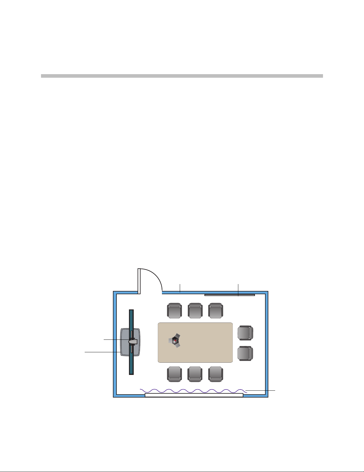
Room Layout Examples
Use the following diagrams as examples for setting up a conference room with
Polycom HDX systems. Polycom recommends that you contract an
experienced contractor to assure all the components operate as a single
cohesive system.
Small Conference Room
Polycom, Inc. 1–1
Page 18
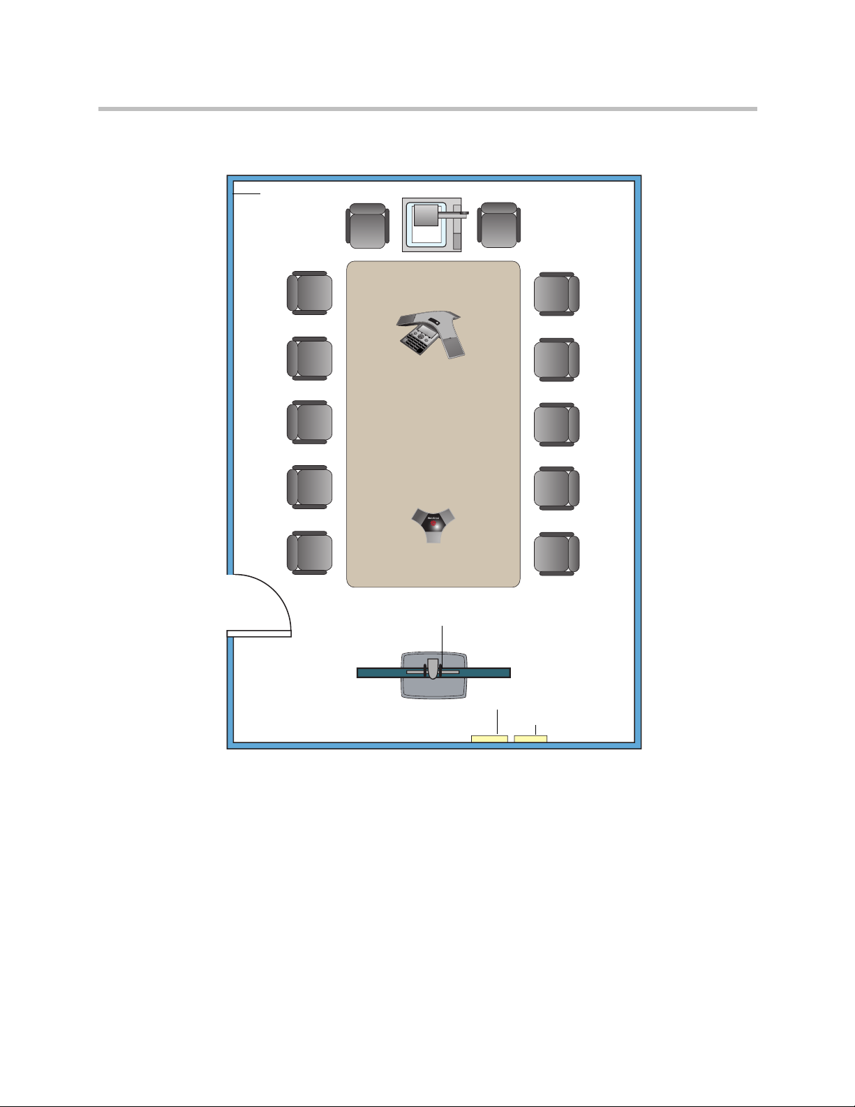
Integrator’s Reference Manual for Polycom HDX Systems
Document Camera
Polycom
Power Outlets
Network Outlets
Flat Panel
Flat Panel
Polycom HDX system
Acoustic Panels
Monitor 1
Monitor 2
Polycom HDX
Microphone
and EagleEye HD camera
Media Center
Polycom SoundStation®
IP 7000 Phone
Large Conference Room
7000
IP
tion
ta
dS
n
u
So
1–2 Polycom, Inc.
Page 19
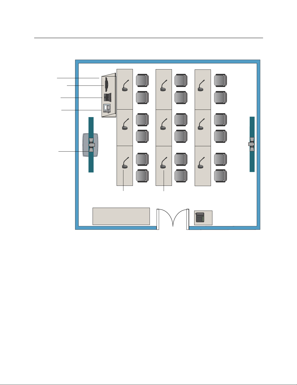
Classroom
Computer
Document
Monitor 1
Monitor for
Polycom
Camera 2
Table-Top Microphones
Teacher’s
Monitor 2
Touch Panel
VGA Out
Podium
Camera
HDX system
with EagleEye
HD camera
and Polycom
SoundStructure™
mixer
Room Integration
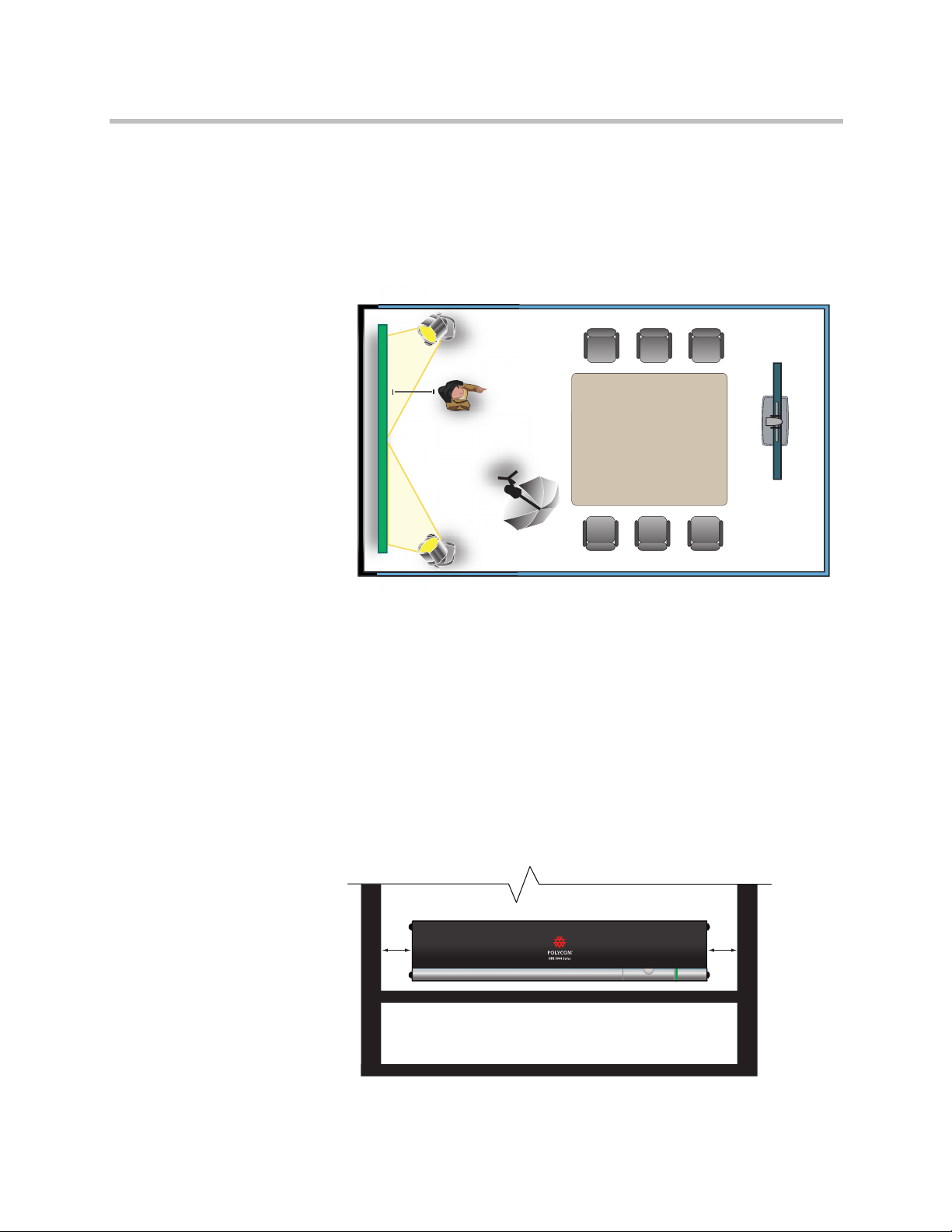
Setting Up the Room for Polycom People On Content™
For the best results, follow these guidelines for setting up Polycom People On
Polycom, Inc. 1–3
Content™:
• Use the Polycom EagleEye™ HD camera with Polycom HDX 9000 series
and Polycom HDX 8000 series systems. Polycom recommends using a
Polycom EagleEye HD or Polycom EagleEye HD 1080 camera with People
on Content. If you are using a Polycom EagleEye 1080 or Polycom
EagleEye View camera, activating People on Content automatically
reduces the resolution to 720p.
• Create a flat, consistent background color using a screen or matte-finish
paint in green or blue. Make sure the background does not have shadows
or glare.
Page 20
Integrator’s Reference Manual for Polycom HDX Systems
3 ft
250 W
250 W
250 W
Polycom HDX
system and
EagleEye HD
camera
• Make sure that the background and the presenter are well lit. For example,
use a minimum of two 250 W halogen lights on the background and one
on the presenter.
• Experiment with different room and lighting arrangements until the best
results are achieved.
You can find more information about configuring and using People On
Content in the User’s Guide for Polycom HDX Systems and in the Knowledge
Base on the Polycom web site.
Polycom HDX Installation Precautions
If you place the Polycom HDX series system in a cart or credenza, ensure that
there is proper ventilation for maintaining an ambient temperature of 40°C or
lower.
Polycom recommends ventilation gaps of at least 2 inches (50.80 mm) on the
left and right of the system with appropriate access to fresh air.
2”
2”
1–4 Polycom, Inc.
Page 21
Integrating Video
1
1
The following sections describe how to connect cameras to Polycom HDX
systems. After you connect a camera to a Polycom HDX system, refer to the
Administrator’s Guide for Polycom HDX Systems for information about
configuring the camera options in the user interface.
Connecting Polycom Cameras
You can connect Polycom HDX systems to a Polycom EagleEye 1080, Polycom
EagleEye HD, Polycom EagleEye View, Polycom PowerCam™, or PowerCam
Plus camera from Polycom, or to other supported cameras. Refer to the release
notes for the software release installed on the Polycom HDX system for a list
of supported PTZ cameras.
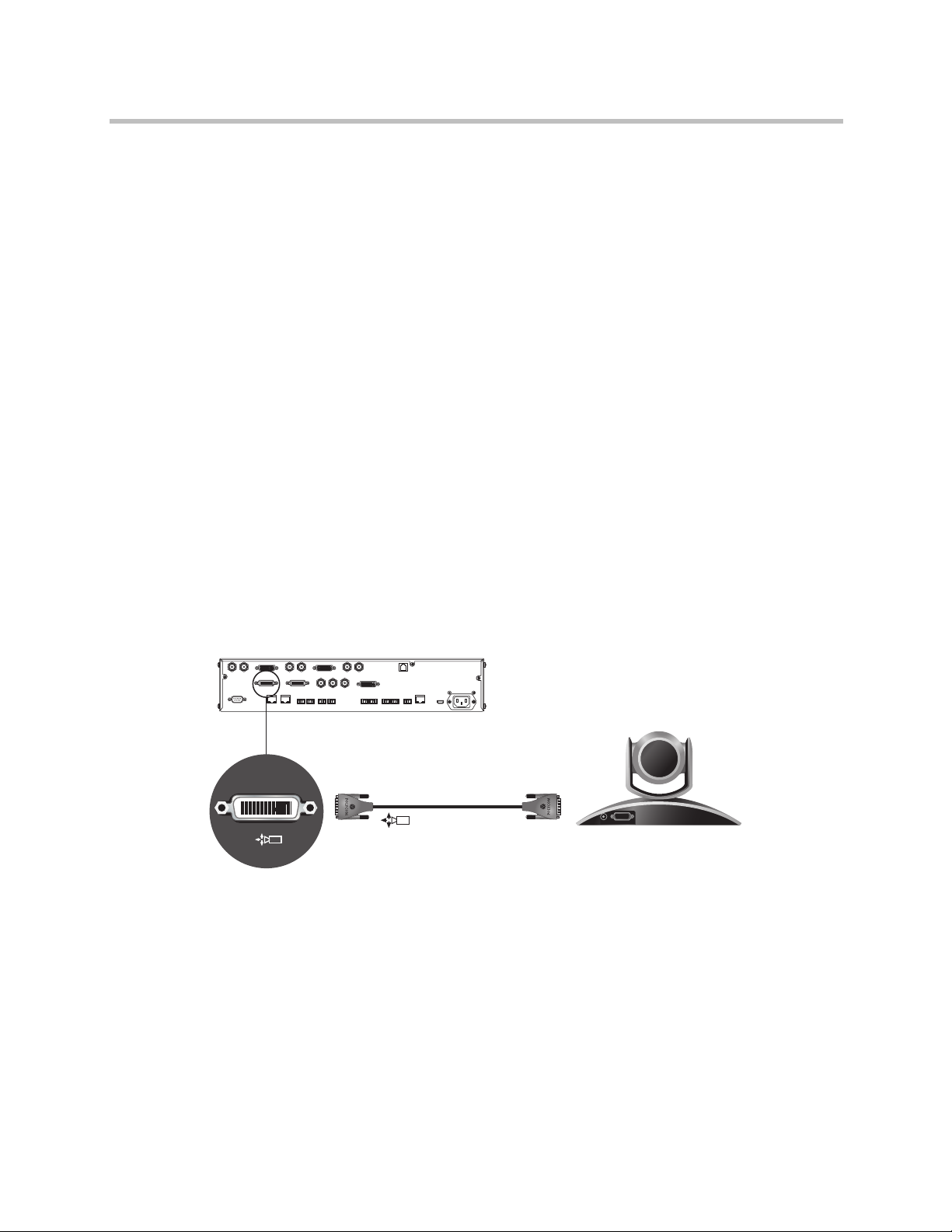
Polycom EagleEye HD Camera as the Main Camera up to 30 ft Away
Room Integration
You can connect a Polycom EagleEye HD camera (part number 8200-23600-001
or 8200-23610-001) to a Polycom HDX 9000 Series system as the main camera
using:
• HDCI Analog Camera Cable on page 2-24
Polycom, Inc. 1–5
Page 22
Integrator’s Reference Manual for Polycom HDX Systems
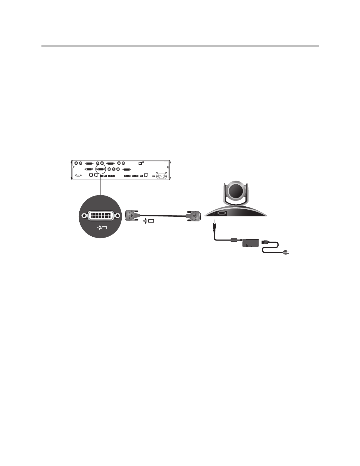
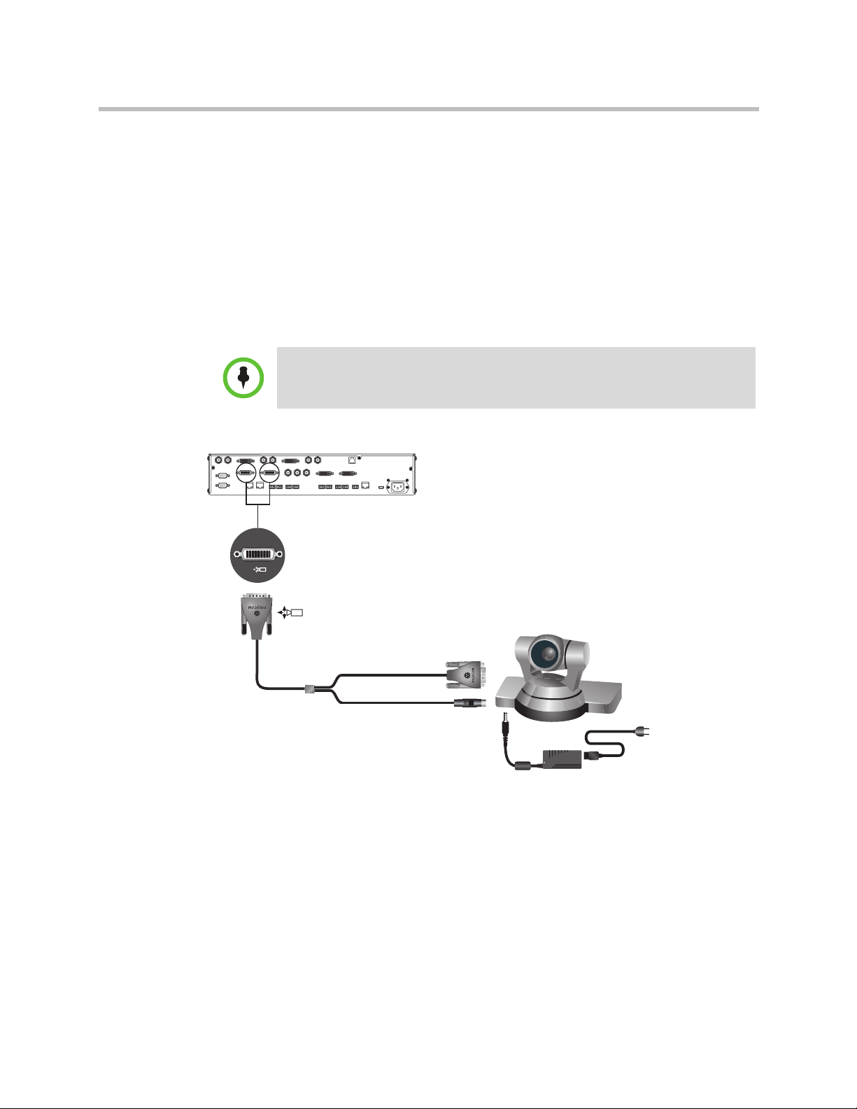
Polycom EagleEye HD Camera as the Second Camera up to 30 ft Away
You can connect a Polycom EagleEye HD camera (part number 8200-23600-001
or 8200-23610-001) to a Polycom HDX 9000 Series system as the second
camera using:
• HDCI Analog Camera Cable on page 2-24 .
• Power supply. Use only the approved power supply from Polycom (part
number 1465-52621-036). Do not exceed 12 Volts at 3 Amps. Verify the
polarity of the power supply as shown on the Polycom camera next to the
power supply input.
2
2
DC IN 12V
1–6 Polycom, Inc.
Page 23
Room Integration
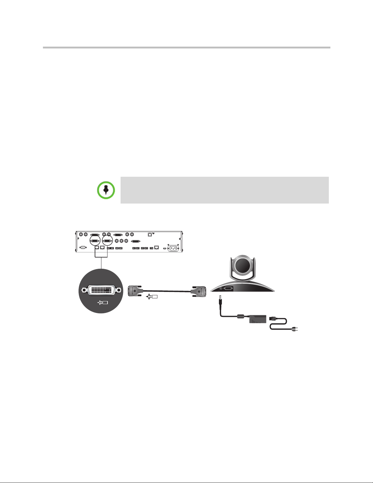
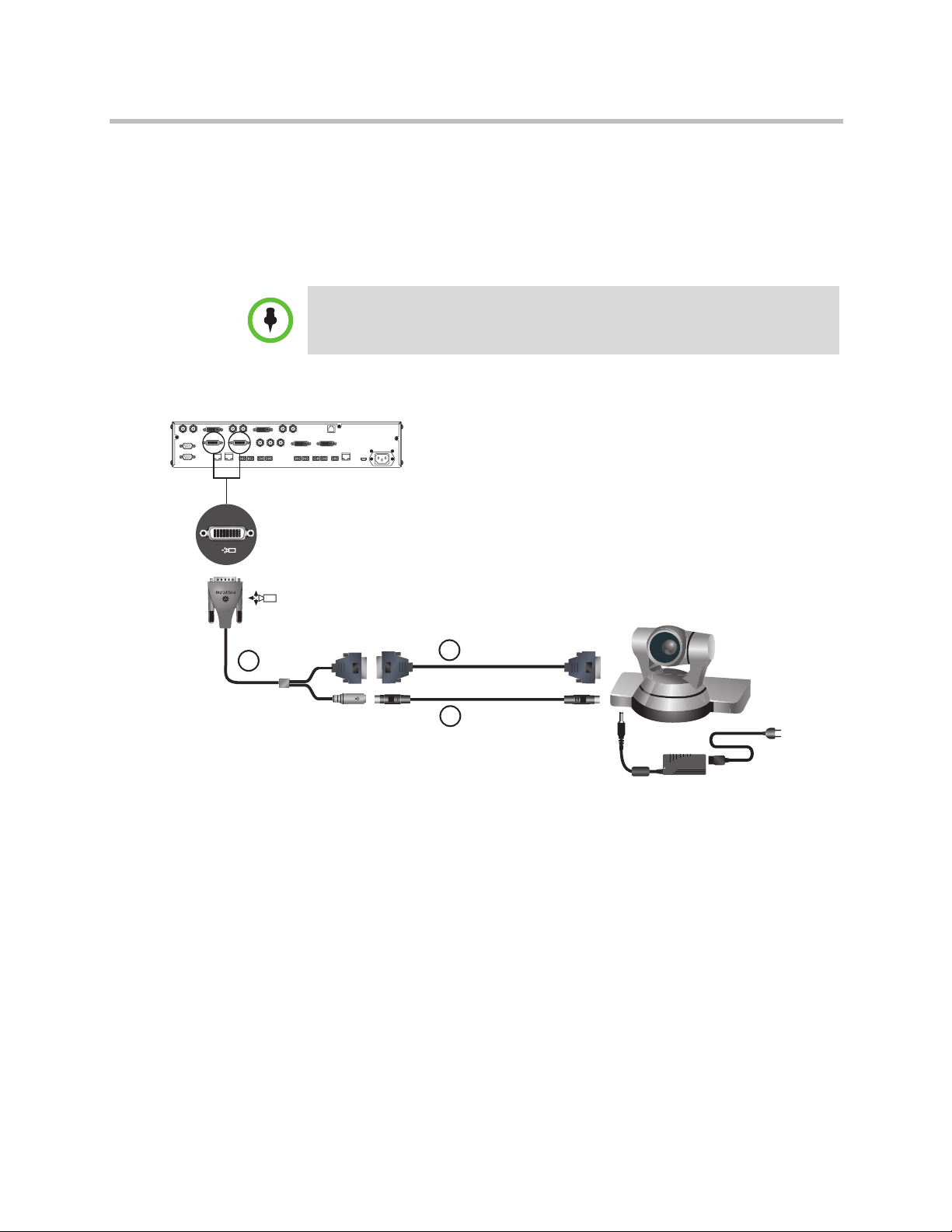
Polycom EagleEye HD Camera as the Main or Second Camera up to 100 ft Away
To connect a Polycom EagleEye HD camera (part number 8200-23600-001 or
8200-23610-001) to a Polycom HDX 9000 Series system more than 30 ft away:
Option 1
• HDCI Analog Camera Cable on page 2-24 .
• Power supply. Use only the approved power supply from Polycom (part
number 1465-52621-036). Do not exceed 12 Volts at 3 Amps. Verify the
polarity of the power supply as shown on the Polycom camera next to the
power supply input.
Polycom recommends this configuration when a custom cable length is not
required.
50 ft or 100 ft
DC IN 12V
Polycom, Inc. 1–7
Page 24
Integrator’s Reference Manual for Polycom HDX Systems
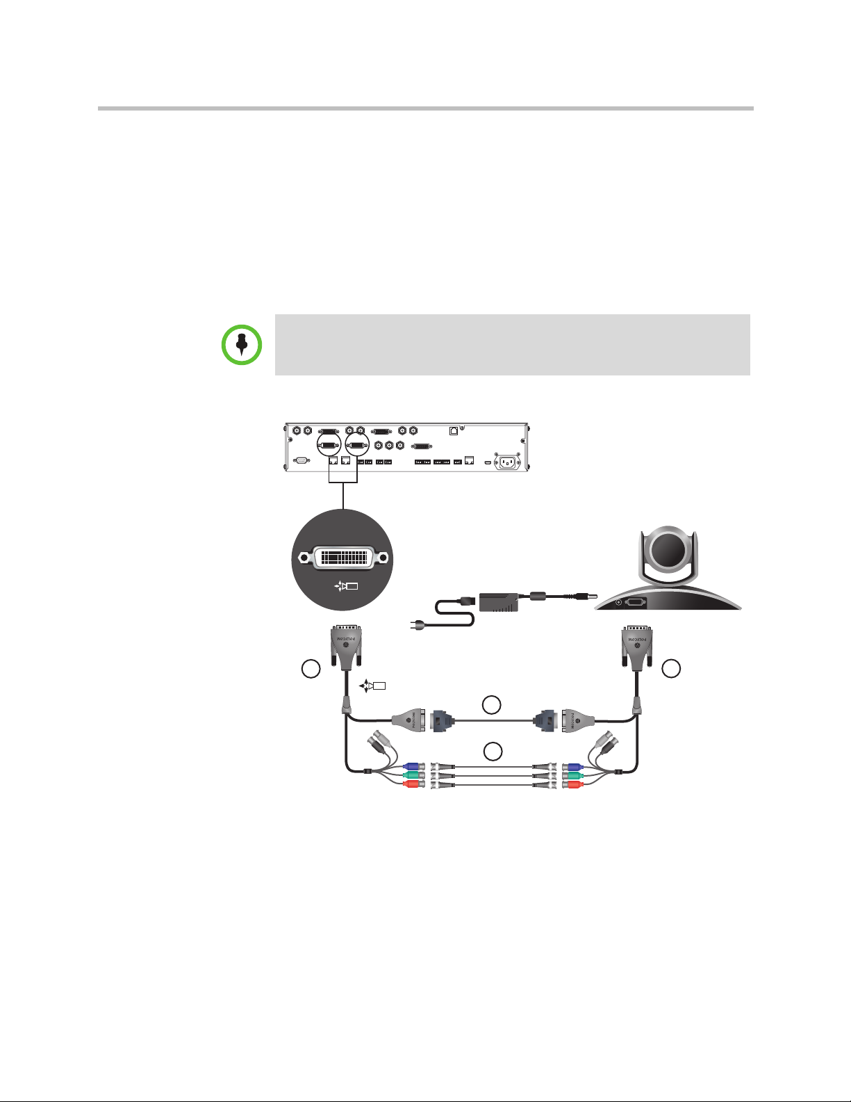
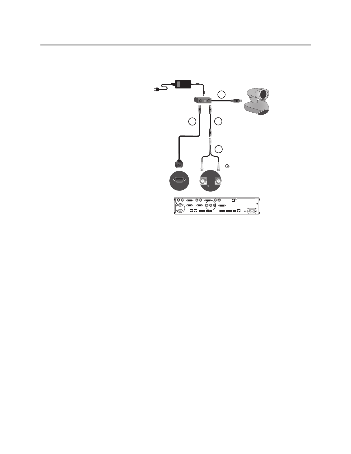
Option 2
• A—Two HDCI Camera Break-Out Cable on page 2-26 .
• B—Coaxial analog video cables
• C—DB-9 serial cable
• Power supply. Use only the approved power supply from Polycom (part
number 1465-52621-036). Do not exceed 12 Volts at 3 Amps. Verify the
polarity of the power supply as shown on the Polycom camera next to the
power supply input.
Polycom recommends this configuration when a custom cable length is required.
The BNC and serial cables can be built to custom lengths.
DC IN 12V
A
A
C
B
Optional, up to 100 ft
1–8 Polycom, Inc.
Page 25
Room Integration
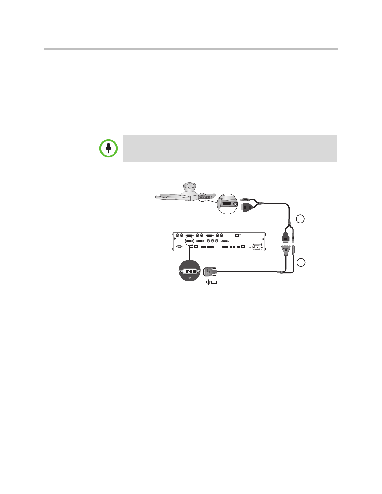
Polycom EagleEye 1080 or Sony EVI-HD1 PTZ as the Main or Second Camera
You can connect a Polycom EagleEye 1080 or Sony EVI-HD1 PTZ camera to a
Polycom HDX 9000 Series system as the main or second camera using:
Option 1
• HDCI Polycom EagleEye 1080 Camera Cable on page 2-33 (this cable is
compatible with the Sony EVI-HD1 PTZ camera)
Polycom recommends this configuration when a custom cable length is required.
Polycom, Inc. 1–9
Page 26
Integrator’s Reference Manual for Polycom HDX Systems
Up to 100 ft
C
A
B
Up to 100 ft
Option 2
• A—HDCI Sony adapter cable on page HDCI Sony VISCA Adapter Cable
on page 2-35 .
• B—VGA cable
• C—VISCA cable
Polycom recommends this configuration when a custom cable length is required.
1–10 Polycom, Inc.
Page 27
Room Integration
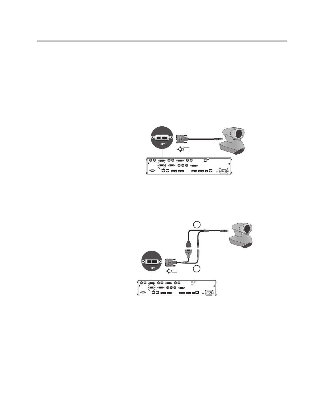
PowerCam as the Main Camera up to 10 ft Away
You can connect a PowerCam (part number 2215-50370-001) to a Polycom HDX
9001, Polycom HDX 9002, or Polycom HDX 9004 system as the main camera
up to 10 ft away using:
Option 1
• HDCI PowerCam Cable on page 2-30
1
1
Option 2
• A—PowerCam Primary Camera Cable on page 2-37
• B— HDCI PowerCam Plus Adapter Cable on page 2-31
A
1
1
B
Polycom, Inc. 1–11
Page 28
Integrator’s Reference Manual for Polycom HDX Systems
2
2
A
B
C
D
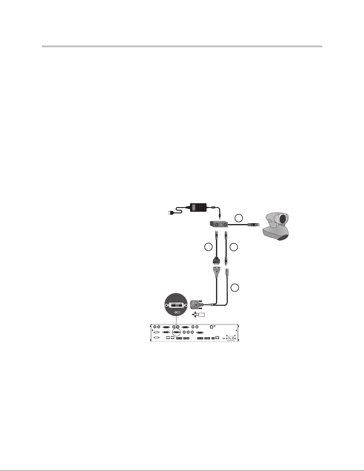
PowerCam as the Second Camera
The following kits are available, which include the power supply, PowerCam
Break-Out cable, 8-pin mini-DIN to DB-9 cable, and S-Video cable:
• 7230-22231-001 (50 ft)
• 7230-22232-001 (100 ft)
You can connect a PowerCam (part number 2215-50370-001) to a Polycom HDX
9001, Polycom HDX 9002, or Polycom HDX 9004 system as the second camera
using:
• A— PowerCam Break-Out Cable on page 2-38
• B— 8-pin mini-DIN to DB-9 on page 2-40
• C— S-Video Cable on page 2-14
• D— HDCI PowerCam Plus Adapter Cable on page 2-31
• Power Supply (part number 1465-52621-036)
You can connect a PowerCam (part number 2215-50370-001) to a Polycom HDX
9001, Polycom HDX 9002, or Polycom HDX 9004 system as the third camera
using:
• A— PowerCam Break-Out Cable on page 2-38
• B— 8-pin mini-DIN to DB-9 on page 2-40
• C— S-Video Cable on page 2-14
1–12 Polycom, Inc.
Page 29
• D—BNC to S-Video Cable on page 2-15
• Power Supply (part number 1465-52621-036)
A
Room Integration
B
C
D
IOIOIO
IOIOIO
If you connect a PTZ camera to a serial port, set RS-232 Mode to Camera PTZ
on the Serial Ports screen.
YC
VCR/DVD
3
VCR/DVD
3
Polycom, Inc. 1–13
Page 30
Integrator’s Reference Manual for Polycom HDX Systems
PowerCam Plus as the Main Camera up to 10 ft Away
You can connect a PowerCam Plus (part number 2215-50200-001) to a Polycom
HDX 9001, Polycom HDX 9002, or Polycom HDX 9004 system as the main
camera up to 10 ft away using:
• A— PowerCam Plus Primary Cable on page 2-29
• B— HDCI PowerCam Plus Adapter Cable on page 2-31
Automatic camera tracking is not available when using the PowerCam Plus camera
with a Polycom HDX system.
A
B
1
1
1–14 Polycom, Inc.
Page 31

Room Integration
B
A
2
2
PowerCam Plus as the Second Camera up to 10 ft Away
You can connect a PowerCam Plus (part number 2215-50200-001) to a Polycom
HDX 9001, Polycom HDX 9002, or Polycom HDX 9004 system as the second
camera up to 10 ft away using:
• A— PowerCam Plus Primary Cable on page 2-29
• B— HDCI PowerCam Plus Adapter Cable on page 2-31
• Power Supply (part number 1465-52621-036)
Automatic camera tracking is not available when using the PowerCam Plus camera
with a Polycom HDX system
Polycom, Inc. 1–15
Page 32

Integrator’s Reference Manual for Polycom HDX Systems
Up to 100 ft
A
B
C
Connecting Sony and ELMO Cameras
Refer to the release notes for a list of supported Pan/Tilt/Zoom (PTZ)
cameras.
Sony or ELMO PTZ as the Main or Second Camera
To connect a Sony or ELMO PTZ camera to a Polycom HDX 9000 Series system
as the main or second camera:
You can connect a Sony or ELMO PTZ camera to a Polycom HDX system
using:
• A— HDCI Sony VISCA Adapter Cable on page 2-35
• B— S-Video Cable on page 2-14
• C—Sony VISCA cable
1–16 Polycom, Inc.
Page 33

Room Integration
Up to 100 ft
A
B
C
IOIOIO
IOIOIO
Sony BRC-H700 PTZ
To connect a Sony BRC-H700 PTZ camera to a Polycom HDX 9000 Series system:
You can connect a Sony BRC-H700 PTZ camera to a Polycom HDX system
using:
• A— DVI to VGA Monitor Cable on page 2-17
• B— 8-pin mini-DIN to DB-9 on page 2-40
• C—VGA extension cable
To provide XGA output (1024x768), you must install the optional Sony HFBK-XG1
card into the slot on the back of the Sony BRC-H700 PTZ camera.
Another option is to use a VGA cable for cable C and to use a VGA/DVI-A adapter
(part number 1517-52689-001) for cable A. The VGA/DVI-A adapter is a solid
overmolded adapter that connects to the Polycom HDX 9000 Series system side of
cable C and adapts from cable C’s VGA connector to a DVI-A connector to plug into
the Polycom HDX 9000 Series system.
Polycom, Inc. 1–17
Page 34

Integrator’s Reference Manual for Polycom HDX Systems
Connecting Vaddio and Canon Cameras
Refer to the release notes for a list of supported Pan/Tilt/Zoom (PTZ)
cameras.
Vaddio or Canon PTZ as the Main or Second Camera
To connect a Vaddio or Canon PTZ camera to a Polycom HDX 9000 Series system
as the main or second camera:
You can connect a Vaddio 70, Vaddio 100, or Canon (with VISCA cable shoe)
PTZ camera to a Polycom HDX system using:
• A— HDCI VISCA Adapter Cable on page 2-32
• B—DB-9 serial cable
• C—S-Video Cable on page 2-14
B
Up to 100 ft
A
Up to 100 ft
C
A separate power supply is required regardless of which connector is used on the
HDX 9000 Series back panel.
1–18 Polycom, Inc.
Page 35

Room Integration
Up to 100 ft
Quick-Connect
Box
RJ45
A
B
C
Vaddio 300 PTZ as the Main or Second Camera
To connect a Vaddio 300 PTZ camera to a Polycom HDX 9000 Series system as
the main or second camera:
You can connect a Vaddio 300 PTZ camera to a Polycom HDX system using:
• A—HDCI VISCA Adapter Cable on page 2-32
• B—DB-9 serial cable
• C—S-Video Cable on page 2-14
Note: For situations that require extraordinary cable lengths, CAT5 extension
kits for camera video, power, and control are available from third-party
vendors.
Polycom, Inc. 1–19
Page 36

4
2
1
100-240VAC 50/60Hz 4A
LAN
IR
3
VCR/DVD
1
4
Y
C
3
VCR/DVD
Y
C
VCR/DVD
3
3
VCR/DVD
1
2
Y
C
1
1
IOIOIO
Y C
1
A
B
C
Integrator’s Reference Manual for Polycom HDX Systems
Integrating Audio and Content
Connecting a Computer to a Polycom HDX 9000 Series System
You can connect Polycom HDX™ 9000 series systems to a computer.
To connect a computer to a Polycom HDX 9001 or Polycom HDX 9002 system:
Option 1
Connect a Polycom HDX™ 9001 or Polycom HDX 9002 system to a computer
using
• A—DVI to VGA Monitor Cable on page 2-17
• B—3.5 mm stereo to RCA adapter cable
• C- Audio Adapter Cable on page 2-49
When you connect a computer to a Polycom HDX 9001 or Polycom HDX 9002
as follows, audio is only heard at the far site and may be heard even when
video input 4 is not selected.
1–20 Polycom, Inc.
Page 37

Room Integration
Option 2
To hear audio at both the near site and the far site, use a bypass mixer to
connect a computer to the Polycom HDX 9001 or Polycom HDX 9002 system
as the following figure shows.
4
Y
YC
1
IOIOIO
1
Y
C
2
1
2
Y
3
VCR/DVD
1
3
1
C
VCR/DVD
3
C
VCR/DVD
4
VCR/DVD
IR
3
1
LAN
100-240VAC 50/60Hz 4A
1
Polycom, Inc. 1–21
Page 38

Integrator’s Reference Manual for Polycom HDX Systems
To connect a computer to a Polycom HDX 9004 system:
Connect a Polycom HDX 9004 system to a computer using
• A—DVI to VGA Monitor Cable on page 2-17
• B—3.5 mm stereo to RCA adapter cable
• C- Audio Adapter Cable on page 2-49 (Polycom HDX 9004, Polycom HDX
9002, and Polycom HDX 9001 systems only.)
When you connect a computer to video input 4 and audio input 4 on a
Polycom HDX 9004 as follows, audio from input 4 is muted unless video
input 4 is selected as a video source.
A
4
B
Y C
1
2
IOIOIO
1
Y
Y
C
2
2
1
C
Y
3
VCR/DVD
1
3
4
C
VCR/DVD
3
VCR/DVD
4
4
C
4
5
VCR/DVD
1
IR
3
LAN
100-240VAC 50/60Hz 4A
1–22 Polycom, Inc.
Page 39

Room Integration
To connect a computer to a Polycom HDX 9006 system:
Connect a Polycom HDX 9006 system to a computer using:
• A—DVI to VGA Monitor Cable on page 2-17
• B—3.5 mm stereo to dual 3-pin Phoenix connectors cable
When you connect a computer to video input 4 and audio input 4 on a
Polycom HDX 9006 system as follows, audio from input 4 is muted unless
video input 4 is selected as a video source.
Polycom, Inc. 1–23
Page 40

Integrator’s Reference Manual for Polycom HDX Systems
Connecting a Vortex® Mixer to a Polycom HDX 9000 Series System
Polycom strongly recommends using Polycom InstantDesigner™ to get started with
your Vortex® mixer integration. InstantDesigner resolves many common issues
with connections and configuration settings.
To use a Polycom HDX system with audio input from a Vortex mixer, set the Input
Type to Line Input and disable Echo Canceller.
Connect a Polycom HDX system to the Vortex mixer using:
• Vortex cable shown on page Vortex Cable on page 2-51
A
A
B
B
YC
1
2
IOIOIO
1
IOIOIO
Y
Y
C
2
2
1
Y
3
VCR/DVD
1
3
1
C
VCR/DVD
4
3
C
VCR/DVD
4
5
VCR/DVD
4
1
IR
3
100-240VAC 50/60Hz 4A
LAN
1
1–24 Polycom, Inc.
Page 41

Room Integration
2
1
100-240VAC 50/60Hz 4A
LAN
IR
5
4
3
VCR/DVD
1
4
Y
C
3
VCR/DVD
Y
C
VCR/DVD
3
4
3
VCR/DVD
1
2
Y
C
1
2
1
IOIOIO
YC
CAV 052-09
zH 06/05
PIN 2: TXD
PIN 3: RXD
PIN 5: GROUND
PIN 7: CTS
PIN 8: RTS
LAN
C-LINK2
OBAM IR
RS-232
REMOTE CONTROL 2
REMOTE CONTROL 1
IN OUT
1 2345678910111213141516
12345678910111213141516
S
TUPTUO
ST
UP
N
I
SoundStructure C16
TM
12V
Connecting a Polycom SoundStructure C-Series Mixer to a Polycom HDX 9000 Series System
Connect a Polycom HDX system to the Polycom SoundStructure C-Series
mixer using:
• Polycom HDX Microphone Host Cable on page 2-41
The microphone input of the Polycom HDX 9000 Series system can support one
SoundStructure C-Series mixer that has up to four Polycom HDX microphones
connected to it. For more information about using the SoundStructure C-Series
mixer with a Polycom HDX system, refer to the SoundStructure C-Series
documentation on the Polycom web site.
You cannot connect both a SoundStructure C-Series mixer and a SoundStation IP
7000 phone to the Polycom HDX 9000 Series system at the same time.
Polycom, Inc. 1–25
Page 42

Integrator’s Reference Manual for Polycom HDX Systems
1–26 Polycom, Inc.
Page 43

Cables
T568B Pair
2
This chapter includes information about cables that can be used with a
Polycom HDX system. Please note that drawings and part numbers are
provided for reference only. Compliance information is provided for the
Restriction of certain Hazardous Substances Directive (RoHS).
Network Cables
CAT 5e LAN Cable
This cable connects a Polycom HDX system to the LAN. It has orange RJ-45
connectors on both ends. It meets category 5e requirements and is wired
according to EIA/TIA-568B. The maximum approved length for this cable is
100 ft (30 m) on an 802 network.
Length Part Number RoHS Compliant
12 ft (3.6 m) 2457-23537-001 Yes
T568B Pair
Polycom, Inc. 2–1
Page 44

Integrator’s Reference Manual for Polycom HDX Systems
Drawings and part numbers are provided for reference only. Polycom claims no
responsibility or liability for the quality, performance, or reliability of cables based on
these reference drawings, other than cables provided by Polycom. Contact your
Polycom distributor or Polycom Custom/Vertical Products to order cables that meet
the appropriate manufacturing tolerances, quality, and performance parameters for
your application.
2–2 Polycom, Inc.
Page 45

LAN Cable
CONN. RJ-45
( x2 )
12 FEET +/- 3"
P2
P1
PIN 8
PIN 8
11
22
33
44
55
66
77
88
PIN#PIN
#
P2P1
Cables
This cable connects a Polycom HDX system to the LAN. It has orange RJ-45
connectors on both ends and is used with all systems. The maximum approved
length for this cable is 100 ft (30 m).
Length Part Number RoHS Compliant
12 ft (3.6 m) 2457-08343-001 Yes
Drawings and part numbers are provided for reference only. Polycom claims no
responsibility or liability for the quality, performance, or reliability of cables based on
these reference drawings, other than cables provided by Polycom. Contact your
Polycom distributor or Polycom Custom/Vertical Products to order cables that meet
the appropriate manufacturing tolerances, quality, and performance parameters for
your application.
Polycom, Inc. 2–3
Page 46

Integrator’s Reference Manual for Polycom HDX Systems
ISDN Cable
This cable connects a Polycom HDX system to a BRI or PRI line. It has clear
RJ-45 connectors on both ends and is used with all Polycom HDX systems that
have ISDN capability. The maximum approved length for this cable is 50 ft
(15 m).
Length Part Number RoHS Compliant
20 ft (6.6 m) 2457-08548-001 Yes
Drawings and part numbers are provided for reference only. Polycom claims no
responsibility or liability for the quality, performance, or reliability of cables based on
these reference drawings, other than cables provided by Polycom. Contact your
Polycom distributor or Polycom Custom/Vertical Products to order cables that meet
the appropriate manufacturing tolerances, quality, and performance parameters for
your application.
2–4 Polycom, Inc.
Page 47

Cables
Pin 8
Pin 1
Signal Name
Receive Ring
Receive Tip
No Connection
Transmit Ring
Transmit T ip
No Connection
No Connection
No Connection
Pin
1
2
3
4
5
6
7
8
PRI Pin Assignments
The following illustration and table show the pin assignments for the PRI port
on the Polycom HDX system.
Polycom, Inc. 2–5
Page 48

Integrator’s Reference Manual for Polycom HDX Systems
Analog Telephone (POTS) Cable
This cable connects a Polycom HDX system to an analog telephone line. It has
pink RJ-11 connectors on both ends. The maximum approved length for this
cable is 100 ft (30 m).
Length Part Number RoHS Compliant
12 ft (3.6 m) 2457-20071-001 Yes
Drawings and part numbers are provided for reference only. Polycom claims no
responsibility or liability for the quality, performance, or reliability of cables based on
these reference drawings, other than cables provided by Polycom. Contact your
Polycom distributor or Polycom Custom/Vertical Products to order cables that meet
the appropriate manufacturing tolerances, quality, and performance parameters for
your application.
2–6 Polycom, Inc.
Page 49

V.35/RS-449/RS-530 Serial Adapter
Notes (direction from V.35 module (DTE))
68 pin Signal Name Signal Type From card Function V.35 RS530-DB25 RS4449-DB37 RS366-DB25
Shield V.35/RS449/RS530 A 19 7,18,19#
12 Receive Data A Differential in V.35/RS449/RS530 R 3 6
11 Receive Data B Differential in V.35/RS449/RS530 T 16 24
10 Send Timing A Differential in V.35/RS449/RS530 Y 15 5
9 Send Timing B Differential in V.35/RS449/RS530 AA 12 23
29 Data Set Ready (DSR) Single Ended in V.35 E
28 Request To Send (RTS) Single Ended out V.35 C
27 Data Terminal Ready (DTR) Single Ended out V.35 H
34 Digit Present (DPR) Single Ended out RS366 2
24 Abandon Call/Retry (ACR) Single Ended in RS366 3
32 Call Request (CRQ) Single Ended out RS366 4
26 Present Next Digit (PND) Single Ended in RS366 5
21 Data Line Occupied (DLO) Single Ended in RS366 22
14 Receive Timing A Differential in V.35/RS449/RS530 V 17 8
13 Receive Timing B Differential in V.35/RS449/RS530 X 9 26
8 Terminal Timing A Differential out V.35/RS449/RS530 U 24 17
7 Terminal Timing B Differential out V.35/RS449/RS530 W 11 35
15 Request To Send (RTS) A Differential out RS449/RS530 4 7
16 Request To Send (RTS) B Differential out RS449/RS530 19 25
35** Receive Common Gnd RS449 20
20 BCD Dial Digit Bit 1 (NB1) Single Ended out RS366 14
19 BCD Dial Digit Bit 2 (NB2) Single Ended out RS366 15
23 BCD Dial Digit Bit 4 (NB4) Single Ended out RS366 16
25 BCD Dial Digit Bit 8 (NB8) Single Ended out RS366 17
2** Signal Ground Gnd V.35/RS366 B 7,18,19
6 Send Data A Differential out V.35/RS449/RS530 P 2 4
5 Send Data B Differential out V.35/RS449/RS530 S 14 22
reserved (Ascend select line)
63 Clear To Send (CTS) A Differential in RS449/RS530 5 9
64 Clear To Send (CTS) B Differential in RS449/RS530 13 27
61 Data Mode (DM-DSR) A Differential in RS449/RS530 6 11
62 Data Mode (DM-DSR) B Differential in RS449/RS530 22 29
65 Receiver Ready (RR-DCD) A Differential in RS449/RS530 8 13
66 Receiver Ready (RR-DCD) B Differential in RS449/RS530 10 31
4** Send Common Gnd RS530 7 37
33 Data Carrier Detect (DCD) Single Ended in V.35 F
18 Terminal Ready (TR-DTR) A Differential out RS449/RS530 20 12
17 Terminal Ready (TR-DTR) B Differential out RS449/RS530 23 30
3 V.35 Cable Connected ground to indicate a V.35 cable is attached 7,18,19*
1 RS449 Cable Connected ground to indicate a RS449 cable is attached 7,18,19^#
22
Distant Station Connected (DSC)
Single Ended in RS366 13
30 Clear To Send (CTS) Single Ended in V.35 D
31
Ring Indicate (RI) (Incoming Call)
Single Ended in V.35/RS449 J 15
reserved (Ascend select line)
68 LOS A Differential out RS530 crypto 18 3
67 LOS B Differential out RS530 crypto 21 21
* For V.35, connect pin 3 of 68 pin connector to ground
^For RS449, connect pin 1 of 68 pin connector to ground
#For RS530, connect pins 1 and 3 of 68 pin connector to ground
** Gnd pins are 2,4, 35-60
Peripheral Link
V.35 HD-68 Pinout
This adapter is used when connecting a Polycom HDX system to other
third-party network equipment. It adapts the 68-pin interface to an industry
standard 44-pin interface used by some network interface equipment. It is
used with Polycom HDX systems that have a V.35/RS-449/RS-530 serial
network interface card (NIC) installed.
Length Part Number RoHS Compliant
6 in (15.23 cm) 2457-21264-200 Yes
Cables
Polycom, Inc. 2–7
Drawings and part numbers are provided for reference only. Polycom claims no
responsibility or liability for the quality, performance, or reliability of cables based on
these reference drawings, other than cables provided by Polycom. Contact your
Polycom distributor or Polycom Custom/Vertical Products to order cables that meet
the appropriate manufacturing tolerances, quality, and performance parameters for
your application.
Page 50

Integrator’s Reference Manual for Polycom HDX Systems
V.35 NIC Cable
This cable connects a Polycom HDX system to Ascend network equipment. It
is used with the V.35/RS-449/RS-530 serial adapter on page
V.35/RS-449/RS-530 Serial Adapter on page 2-7 to connect to network
equipment that has the HD-44 pin interface. It has HD-44 M connectors on
both ends and is used with Polycom HDX systems that have a serial network
interface card (NIC) installed.
Length Part Number RoHS Compliant
5 ft (1.65 m) 2457-10608-200 Yes
Drawings and part numbers are provided for reference only. Polycom claims no
responsibility or liability for the quality, performance, or reliability of cables based on
these reference drawings, other than cables provided by Polycom. Contact your
Polycom distributor or Polycom Custom/Vertical Products to order cables that meet
the appropriate manufacturing tolerances, quality, and performance parameters for
your application.
2–8 Polycom, Inc.
Page 51

V.35 and RS-366 Serial Cable
This cable connects a Polycom HDX system to third-party network equipment.
It is used with the V.35/RS-449/RS-530 serial adapter on page
V.35/RS-449/RS-530 Serial Adapter on page 2-7 to connect to network
equipment that has a V.35/RS-366 interface. It is HD-44 M to “Y” Winchester
34M/RS-366 DB-25M and is used with Polycom HDX systems that have a
serial network interface card (NIC) installed.
Length Part Number RoHS Compliant
5 ft (1.65 m) 2457-10609-200 Yes
Cables
Drawings and part numbers are provided for reference only. Polycom claims no
responsibility or liability for the quality, performance, or reliability of cables based on
these reference drawings, other than cables provided by Polycom. Contact your
Polycom distributor or Polycom Custom/Vertical Products to order cables that meet
the appropriate manufacturing tolerances, quality, and performance parameters for
your application.
Polycom, Inc. 2–9
Page 52

Integrator’s Reference Manual for Polycom HDX Systems
RS-449 and RS-366 Serial Cable
This cable connects a Polycom HDX system to third-party network equipment.
It is used with the V.35/RS-449/RS-530 serial adapter on page
V.35/RS-449/RS-530 Serial Adapter on page 2-7 to connect to network
equipment that has an RS-449/RS-366 interface. It is HD-44 M to “Y” RS-449
DB-37M/RS-366 DB-25M and is used with Polycom HDX systems that have a
serial network interface card (NIC) installed.
Length Part Number RoHS Compliant
5 ft (1.65 m) 2457-10610-200 Yes
2–10 Polycom, Inc.
Page 53

Cables
Drawings and part numbers are provided for reference only. Polycom claims no
responsibility or liability for the quality, performance, or reliability of cables based on
these reference drawings, other than cables provided by Polycom. Contact your
Polycom distributor or Polycom Custom/Vertical Products to order cables that meet
the appropriate manufacturing tolerances, quality, and performance parameters for
your application.
Polycom, Inc. 2–11
Page 54

Integrator’s Reference Manual for Polycom HDX Systems
Peripheral Link V.35 HD-68 Pinout
Notes (direction from V.35 module (DTE))
68 pin Signal Name Signal Type From card Function RS530-DB25 RS366-DB25
Shield V.35/RS449/RS530 7,18,19#
12 Receive Data A Differential in V.35/RS449/RS530 3
11 Receive Data B Differential in V.35/RS449/RS530 16
10 Send Timing A Differential in V.35/RS449/RS530 15
9 Send Timing B Differential in V.35/RS449/RS530 12
29 Data Set Ready (DSR) Single Ended in V.35
28 Request To Send (RTS) Single Ended out V.35
27 Data Terminal Ready (DTR) Single Ended out V.35
34 Digit Present (DPR) Single Ended out RS366 2
24 Abandon Call/Retry (ACR) Single Ended in RS366 3
32 Call Request (CRQ) Single Ended out RS366 4
26 Present Next Digit (PND) Single Ended in RS366 5
21 Data Line Occupied (DLO) Single Ended in RS366 22
14 Receive Timing A Differential in V.35/RS449/RS530 17
13 Receive Timing B Differential in V.35/RS449/RS530 9
8 Terminal Timing A Differential out V.35/RS449/RS530 24
7 Terminal Timing B Differential out V.35/RS449/RS530 11
15 Request To Send (RTS) A Differential out RS449/RS530 4
16 Request To Send (RTS) B Differential out RS449/RS530 19
35** Receive Common Gnd RS449
20 BCD Dial Digit Bit 1 (NB1) Single Ended out RS366 14
19 BCD Dial Digit Bit 2 (NB2) Single Ended out RS366 15
23 BCD Dial Digit Bit 4 (NB4) Single Ended out RS366 16
25 BCD Dial Digit Bit 8 (NB8) Single Ended out RS366 17
2** Signal Ground Gnd V.35/RS366 7,18,19
6 Send Data A Differential out V.35/RS449/RS530 2
5 Send Data B Differential out V.35/RS449/RS530 14
reserved (Ascend select line)
63 Clear To Send (CTS) A Differential in RS449/RS530 5
64 Clear To Send (CTS) B Differential in RS449/RS530 13
61 Data Mode (DM-DSR) A Differential in RS449/RS530 6
62 Data Mode (DM-DSR) B Differential in RS449/RS530 22
65 Receiver Ready (RR-DCD) A Differential in RS449/RS530 8
66 Receiver Ready (RR-DCD) B Differential in RS449/RS530 10
4** Send Common Gnd RS530 7
33 Data Carrier Detect (DCD) Single Ended in V.35
18 Terminal Ready (TR-DTR) A Differential out RS449/RS530 20
17 Terminal Ready (TR-DTR) B Differential out RS449/RS530 23
3 V.35 Cable Connected ground to indicate a V.35 cable is attached 7,18,19*
1 RS449 Cable Connected ground to indicate a RS449 cable is attached 7,18,19^#
22
Distant Station Connected (DSC)
Single Ended in RS366 13
30 Clear To Send (CTS) Single Ended in V.35
31
Ring Indicate (RI) (Incoming Call)
Single Ended in V.35/RS449
reserved (Ascend select line)
68 LOS A Differential out RS530 crypto 18
67 LOS B Differential out RS530 crypto 21
* For V.35, connect pin 3 of 68 pin connector to ground
^For RS449, connect pin 1 of 68 pin connector to ground
#For RS530, connect pins 1 and 3 of 68 pin connector to ground
RS-530 with RS-366 Serial Cable
This cable connects a Polycom HDX system to third-party network equipment.
It is used with the V.35/RS-449/RS-530 serial adapter on page
V.35/RS-449/RS-530 Serial Adapter on page 2-7 to connect to network
equipment that has an RS-530/RS-366 interface. It is HD-68M to “Y” DB-25M
and is used with Polycom HDX systems that have a serial network interface
card (NIC) installed.
Length Part Number RoHS Compliant
5 ft (1.65 m) 2457-21263-200 Yes
2–12 Polycom, Inc.
Page 55

Cables
Drawings and part numbers are provided for reference only. Polycom claims no
responsibility or liability for the quality, performance, or reliability of cables based on
these reference drawings, other than cables provided by Polycom. Contact your
Polycom distributor or Polycom Custom/Vertical Products to order cables that meet
the appropriate manufacturing tolerances, quality, and performance parameters for
your application.
Polycom, Inc. 2–13
Page 56

Integrator’s Reference Manual for Polycom HDX Systems
P3P3 P4P4
P1P1 P2P2
25 FEET +/- 2"25 FEET +/- 2"
P3P3 P4P4
P1P1 P2P2
MINI-DIN MALE 4 POS. ( x2)MINI-DIN MALE 4 POS. ( x2)
Video and Camera Cables
S-Video Cable
These cables connect a Polycom HDX system to a monitor or camera. They
have yellow 4-pin mini-DIN connectors on both ends and are used with all
Polycom HDX systems. The maximum approved length for this cable is 200 ft
(60 m).
Length Part Number RoHS Compliant
8 ft (2.4 m) 2457-08410-002 Yes
25 ft (7.6 m) 2457-08409-002 Yes
50 ft (15 m) 2457-09204-200 Yes
Drawings and part numbers are provided for reference only. Polycom claims no
responsibility or liability for the quality, performance, or reliability of cables based on
these reference drawings, other than cables provided by Polycom. Contact your
Polycom distributor or Polycom Custom/Vertical Products to order cables that meet
the appropriate manufacturing tolerances, quality, and performance parameters for
your application.
2–14 Polycom, Inc.
Page 57

BNC to S-Video Cable
DIMENSIONS ARE IN MILLIMETERSDIMENSIONS ARE IN MILLIMETERS
Cables
This cable connects S-Video devices to a Polycom HDX system. It is 4-pin male
mini-DIN to dual BNC male. The maximum approved length for this cable is
100 ft (30 m).
Length Part Number RoHS Compliant
6 ft (1.8 m) 2457-21489-200 Yes
Drawings and part numbers are provided for reference only. Polycom claims no
responsibility or liability for the quality, performance, or reliability of cables based on
these reference drawings, other than cables provided by Polycom. Contact your
Polycom distributor or Polycom Custom/Vertical Products to order cables that meet
the appropriate manufacturing tolerances, quality, and performance parameters for
your application.
Polycom, Inc. 2–15
Page 58

Integrator’s Reference Manual for Polycom HDX Systems
BNC to S-Video Adapter
This adapter may be required when connecting standard S-Video cables to a
Polycom HDX system. It is dual BNC male to 4-pin female mini-DIN.
Length Part Number RoHS Compliant
1 ft (.3 m) 2457-21490-200 Yes
Drawings and part numbers are provided for reference only. Polycom claims no
responsibility or liability for the quality, performance, or reliability of cables based on
these reference drawings, other than cables provided by Polycom. Contact your
Polycom distributor or Polycom Custom/Vertical Products to order cables that meet
the appropriate manufacturing tolerances, quality, and performance parameters for
your application.
2–16 Polycom, Inc.
Page 59

DVI to VGA Monitor Cable
This cable connects a Polycom HDX system DVI-I output to a VGA monitor.
It can also be used to connect a computer to one of the DVI-A video inputs on
a Polycom HDX system. It is male DVI-A to male HD-15.
Length Part Number RoHS Compliant
4 ft 6 in (1.5 m) 2457-25182-001 Yes
9 ft 10 in (3 m) 2457-23792-001 Yes
25 ft (7.6 m) 2457-23792-025 Yes
Cables
Drawings and part numbers are provided for reference only. Polycom claims no
responsibility or liability for the quality, performance, or reliability of cables based on
these reference drawings, other than cables provided by Polycom. Contact your
Polycom distributor or Polycom Custom/Vertical Products to order cables that meet
the appropriate manufacturing tolerances, quality, and performance parameters for
your application.
Polycom, Inc. 2–17
Page 60

Integrator’s Reference Manual for Polycom HDX Systems
HDMI Monitor Cable
This cable connects the Polycom HDX system DVI-I output to an HDMI
monitor. It is male DVI-D to male HDMI.
Length Part Number RoHS Compliant
9 ft 10 in (3 m) 2457-23905-001 Yes
Drawings and part numbers are provided for reference only. Polycom claims no
responsibility or liability for the quality, performance, or reliability of cables based on
these reference drawings, other than cables provided by Polycom. Contact your
Polycom distributor or Polycom Custom/Vertical Products to order cables that meet
the appropriate manufacturing tolerances, quality, and performance parameters for
your application.
2–18 Polycom, Inc.
Page 61

BNC Monitor Adapter Cable
This cable connects the Polycom HDX system DVI-I output to a variety of
analog display devices with composite, S-Video, component YPbPr, or
RGBHV inputs. It is male DVI-A to five female BNC connectors.
Length Part Number RoHS Compliant
1 ft (0.3 m) 2457-23533-001 Yes
Cables
Drawings and part numbers are provided for reference only. Polycom claims no
responsibility or liability for the quality, performance, or reliability of cables based on
these reference drawings, other than cables provided by Polycom. Contact your
Polycom distributor or Polycom Custom/Vertical Products to order cables that meet
the appropriate manufacturing tolerances, quality, and performance parameters for
your application.
Polycom, Inc. 2–19
Page 62

Integrator’s Reference Manual for Polycom HDX Systems
Polycom HDX Component Monitor Cable
This cable connects a Polycom HDX system DVI-I output to a monitor with
component connections. It is male DVI-A to three RCA.
Length Part Number RoHS Compliant
6 ft (1.8 m) 2457-52698-006 Yes
12 ft (3.6 m) 2457-52698-012 Yes
Drawings and part numbers are provided for reference only. Polycom claims no
responsibility or liability for the quality, performance, or reliability of cables based on
these reference drawings, other than cables provided by Polycom. Contact your
Polycom distributor or Polycom Custom/Vertical Products to order cables that meet
the appropriate manufacturing tolerances, quality, and performance parameters for
your application.
2–20 Polycom, Inc.
Page 63

HDX Component Video Cable
This cable connects a Polycom HDX system to a video playback device with
component connections. It is three RCA to three male BNC.
Length Part Number RoHS Compliant
25 ft (7.6 m) 2457-52688-025 Yes
Drawings and part numbers are provided for reference only. Polycom claims no
responsibility or liability for the quality, performance, or reliability of cables based on
these reference drawings, other than cables provided by Polycom. Contact your
Polycom distributor or Polycom Custom/Vertical Products to order cables that meet
the appropriate manufacturing tolerances, quality, and performance parameters for
your application.
Cables
Polycom, Inc. 2–21
Page 64

Integrator’s Reference Manual for Polycom HDX Systems
DVI-D Monitor Cable
This cable connects a Polycom HDX system DVI-I output to a DVI-D monitor.
It is male DVI-D on both ends.
Length Part Number RoHS Compliant
4 ft 6 in (1.5 m) 2457-25181-001 Yes
9 ft 10 in (3 m) 2457-23793-001 Yes
Drawings and part numbers are provided for reference only. Polycom claims no
responsibility or liability for the quality, performance, or reliability of cables based on
these reference drawings, other than cables provided by Polycom. Contact your
Polycom distributor or Polycom Custom/Vertical Products to order cables that meet
the appropriate manufacturing tolerances, quality, and performance parameters for
your application.
2–22 Polycom, Inc.
Page 65

Component A/V Monitor Cable
This cable connects a Polycom HDX system DVI-I video output and stereo
audio output to a monitor with component video and stereo audio
connections. It is male DVI-A and dual male RCA to five RCA.
You must use the audio adapter cable on page Audio Adapter Cable on
page 2-49 to connect the dual RCA connectors on this component A/V
monitor cable to the dual Phoenix connectors on the Polycom HDX system.
Length Part Number RoHS Compliant
9 ft 10 in (3 m) 2457-24772-001 Yes
Cables
Drawings and part numbers are provided for reference only. Polycom claims no
responsibility or liability for the quality, performance, or reliability of cables based on
these reference drawings, other than cables provided by Polycom. Contact your
Polycom distributor or Polycom Custom/Vertical Products to order cables that meet
the appropriate manufacturing tolerances, quality, and performance parameters for
your application.
Polycom, Inc. 2–23
Page 66

Integrator’s Reference Manual for Polycom HDX Systems
HDCI Analog Camera Cable
This cable connects a Polycom HDX system to a Polycom EagleEye HD
camera. This cable can be connected to the EagleEye View camera, but does
not support audio. It has male HDCI connectors on both ends.
Length Part Number RoHS Compliant
9 ft 10 in (3 m) 2457-23180-003 Yes
33 ft (10 m) 2457-23180-010 Yes
50 ft (15 m) 2457-23180-015 Yes
100 ft (30 m) 2457-23180-030 Yes
Drawings and part numbers are provided for reference only. Polycom claims no
responsibility or liability for the quality, performance, or reliability of cables based on
these reference drawings, other than cables provided by Polycom. Contact your
Polycom distributor or Polycom Custom/Vertical Products to order cables that meet
the appropriate manufacturing tolerances, quality, and performance parameters for
your application.
2–24 Polycom, Inc.
Page 67

HDCI Digital Camera Cable
This cable connects a Polycom HDX system to a Polycom EagleEye HD
camera. It has male HDCI connectors on both ends.
Length Part Number RoHS Compliant
9 ft 10 in (3 m) 2457-23181-003 Yes
Cables
Drawings and part numbers are provided for reference only. Polycom claims no
responsibility or liability for the quality, performance, or reliability of cables based on
these reference drawings, other than cables provided by Polycom. Contact your
Polycom distributor or Polycom Custom/Vertical Products to order cables that meet
the appropriate manufacturing tolerances, quality, and performance parameters for
your application.
Polycom, Inc. 2–25
Page 68

Integrator’s Reference Manual for Polycom HDX Systems
HDCI Camera Break-Out Cable
This cable breaks out the HDCI camera cable video and control signals to
standard interfaces. This cable can be connected to the EagleEye View camera,
but does not support audio.The five BNC connectors can be used to carry
composite video, S-Video, or analog component YPbPr video. The DB-9
connector is used to connect to PTZ camera control interfaces. It is male HDCI
to five female BNC and one female DB-9.
Length Part Number RoHS Compliant
1ft (0.3 m) 2457-23521-001 Yes
Drawings and part numbers are provided for reference only. Polycom claims no
responsibility or liability for the quality, performance, or reliability of cables based on
these reference drawings, other than cables provided by Polycom. Contact your
Polycom distributor or Polycom Custom/Vertical Products to order cables that meet
the appropriate manufacturing tolerances, quality, and performance parameters for
your application.
2–26 Polycom, Inc.
Page 69

VCR/DVD Composite Cable
This cable connects a Polycom HDX system to a VCR or DVD player. It has
triple RCA connectors on both ends. The Polycom HDX system requires a
female RCA to male BNC adapter for the yellow video RCA connector, and the
Audio Adapter Cable on page 2-49 . The maximum approved length for this
cable is 50 ft (15 m).
Length Part Number RoHS Compliant
8 ft (2.6 m) 2457-08412-001 —
Cables
Drawings and part numbers are provided for reference only. Polycom claims no
responsibility or liability for the quality, performance, or reliability of cables based on
these reference drawings, other than cables provided by Polycom. Contact your
Polycom distributor or Polycom Custom/Vertical Products to order cables that meet
the appropriate manufacturing tolerances, quality, and performance parameters for
your application.
Polycom, Inc. 2–27
Page 70

Integrator’s Reference Manual for Polycom HDX Systems
Composite Video Cable
This cable connects a Polycom HDX system to a monitor or camera. It has
single yellow RCA connectors on both ends. The Polycom HDX system
requires a female RCA to male BNC adapter in order to connect to composite
input or output. The maximum approved length for this cable is 100 ft (30 m).
Length Part Number RoHS Compliant
25 ft (7.6 m) 2457-09207-001 —
Drawings and part numbers are provided for reference only. Polycom claims no
responsibility or liability for the quality, performance, or reliability of cables based on
these reference drawings, other than cables provided by Polycom. Contact your
Polycom distributor or Polycom Custom/Vertical Products to order cables that meet
the appropriate manufacturing tolerances, quality, and performance parameters for
your application.
2–28 Polycom, Inc.
Page 71

PowerCam Plus Primary Cable
1576423
8
1514
12
10911
13
1342
Front View
of Connector
1
3
4
2
1576423
8
15
14
12
10911
13
P1
P2
P3
P4
Front View
of Connector
200mm / 7.87"
200mm / 7.87"
3 Meters / 9' 10"
P1 Connector P2 Connector
Pin # Signal Name Pin # Signal Name
1 Arm Mic 1 Arm Mic
2 Left Mic 2 Left Mic
3 A GND 3 A GND
4 Cam ID Bit 4 Cam ID Bit
5 P GND 5 P GND
6 +12V 6 +12V
7 SW-RX/SN-TX 7 SW-RX/SN-TX
8 IR signal 8 IR signal
9 Center Mic 9 Center Mic
10 Right Mic 10 Right Mic
11 A GND 11 A GND
12 P GND 12 P GND
13 +12V 13 +12V
14 SW-TX/SN-RX 14 SW-TX/SN-RX
15 IR return 15 IR return
P3 4 Pin mini Din P4 4 Pin mini Din
1 A GND 1 A GND
2 A GND 2 A GND
3 Luma 3 Luma
4 Chroma 4 Chroma
40mm / 1.57"
40mm / 1.57"
This cable connects a Polycom HDX system to a Polycom PowerCam Plus
camera using the HDCI PowerCam Plus Adapter Cable on page 2-31 . It has
4-pin mini-DIN and DB-15 connectors on both ends.
Length Part Number RoHS Compliant
9 ft 10 in (3 m) 1457-50105-002 Yes
30 ft (9 m) 1457-50105-230 Yes
50 ft (15 m) 1457-50105-250 Yes
100 ft (30 m) 1457-50105-300 Yes
150 ft (45 m) 1457-50105-350 Yes
Cables
Drawings and part numbers are provided for reference only. Polycom claims no
responsibility or liability for the quality, performance, or reliability of cables based on
these reference drawings, other than cables provided by Polycom. Contact your
Polycom distributor or Polycom Custom/Vertical Products to order cables that meet
the appropriate manufacturing tolerances, quality, and performance parameters for
your application.
Polycom, Inc. 2–29
Page 72

Integrator’s Reference Manual for Polycom HDX Systems
HDCI PowerCam Cable
This cable connects a Polycom HDX system to a Polycom PowerCam camera.
It is HDCI to 8-pin mini-DIN.
Length Part Number RoHS Compliant
10 ft (3 m) 2457-28168-001 Yes
Drawings and part numbers are provided for reference only. Polycom claims no
responsibility or liability for the quality, performance, or reliability of cables based on
these reference drawings, other than cables provided by Polycom. Contact your
Polycom distributor or Polycom Custom/Vertical Products to order cables that meet
the appropriate manufacturing tolerances, quality, and performance parameters for
your application.
2–30 Polycom, Inc.
Page 73

HDCI PowerCam Plus Adapter Cable
This cable adapts a PowerCam Plus cable to HDCI. It is HDCI to 4-pin
mini-DIN and DB-15. It can also be used with the PowerCam Primary Camera
Cable on page 2-37 to connect PowerCam.
Length Part Number RoHS Compliant
1 ft (0.3 m) 2457-23481-001 Yes
Cables
Drawings and part numbers are provided for reference only. Polycom claims no
responsibility or liability for the quality, performance, or reliability of cables based on
these reference drawings, other than cables provided by Polycom. Contact your
Polycom distributor or Polycom Custom/Vertical Products to order cables that meet
the appropriate manufacturing tolerances, quality, and performance parameters for
your application.
Polycom, Inc. 2–31
Page 74

Integrator’s Reference Manual for Polycom HDX Systems
HDCI VISCA Adapter Cable
This cable connects a Polycom HDX system HDCI video input to SD cameras
with VISCA control that use a DB-9 serial connector. It is HDCI to 4-pin
mini-DIN and DB-9. Standard S-Video and DB-9 serial cables are required to
connect this cable to the camera.
Length Part Number RoHS Compliant
1 ft (0.3 m) 2457-23486-001 Yes
Drawings and part numbers are provided for reference only. Polycom claims no
responsibility or liability for the quality, performance, or reliability of cables based on
these reference drawings, other than cables provided by Polycom. Contact your
Polycom distributor or Polycom Custom/Vertical Products to order cables that meet
the appropriate manufacturing tolerances, quality, and performance parameters for
your application.
2–32 Polycom, Inc.
Page 75

HDCI Polycom EagleEye 1080 Camera Cable
This cable connects a Polycom HDX system HDCI video input to a Polycom
EagleEye 1080 camera or to a Sony HD camera. The cable is HDCI to 8-pin
mini-DIN and HD-15.
Length Part Number RoHS Compliant
9 ft 10 in (3 m) 2457-28153-001 Yes
33 ft (10 m) 2457-28154-001 Yes
50 ft (15m) 2457-28154-050 Yes
100 ft (30m) 2457-28154-100 Yes
Cables
Drawings and part numbers are provided for reference only. Polycom claims no
responsibility or liability for the quality, performance, or reliability of cables based on
these reference drawings, other than cables provided by Polycom. Contact your
Polycom distributor or Polycom Custom/Vertical Products to order cables that meet
the appropriate manufacturing tolerances, quality, and performance parameters for
your application.
Polycom, Inc. 2–33
Page 76

Integrator’s Reference Manual for Polycom HDX Systems
HDCI Polycom EagleEye View Camera Cable
This cable connects a Polycom HDX system HDCI video input to a Polycom
EagleEye View camera. It has male HDCI connectors on both ends.
Length Part Number RoHS Compliant
9 ft 10 in (3 m) 2457-29759-001 Yes
33 ft (10 m) 2457-29759-010 Yes
Drawings and part numbers are provided for reference only. Polycom claims no
responsibility or liability for the quality, performance, or reliability of cables based on
these reference drawings, other than cables provided by Polycom. Contact your
Polycom distributor or Polycom Custom/Vertical Products to order cables that meet
the appropriate manufacturing tolerances, quality, and performance parameters for
your application.
2–34 Polycom, Inc.
Page 77

HDCI Sony VISCA Adapter Cable
This cable connects a Polycom HDX system HDCI video input to a camera
using Sony 8-pin mini-DIN VISCA and S-Video. It is HDCI to 8-pin mini-DIN
and S-Video. Standard S-Video and Sony VISCA cables are required to connect
this cable to the camera. The VISCA cable is a straight-through male 8-pin
mini-DIN to male 8-pin mini-DIN serial cable.
Length Part Number RoHS Compliant
1 ft (0.3 m) 2457-23549-001 Yes
Cables
Drawings and part numbers are provided for reference only. Polycom claims no
responsibility or liability for the quality, performance, or reliability of cables based on
these reference drawings, other than cables provided by Polycom. Contact your
Polycom distributor or Polycom Custom/Vertical Products to order cables that meet
the appropriate manufacturing tolerances, quality, and performance parameters for
your application.
Polycom, Inc. 2–35
Page 78

Integrator’s Reference Manual for Polycom HDX Systems
HDCI EagleEye 1080 or Sony Adapter Cable
This cable connects a Polycom system HDCI video input to the Polycom
EagleEye 1080, Sony EVI-HD1 PTZ or Sony BRC-H700 PTZ cameras. It is
HDCI to 8-pin mini-DIN and HD-15. The maximum approved length for this
cable is 100 ft (30 m).
Length Part Number RoHS Compliant
1 ft (0.3 m) 2457-23548-001 Yes
Drawings and part numbers are provided for reference only. Polycom claims no
responsibility or liability for the quality, performance, or reliability of cables based on
these reference drawings, other than cables provided by Polycom. Contact your
Polycom distributor or Polycom Custom/Vertical Products to order cables that meet
the appropriate manufacturing tolerances, quality, and performance parameters for
your application.
2–36 Polycom, Inc.
Page 79

PowerCam Primary Camera Cable
This cable connects the Polycom HDX system video input 1 to a Polycom
PowerCam camera up to 10 ft away when used with the HDCI PowerCam
Plus Adapter Cable on page 2-31 . It is 8-pin mini-DIN to 4-pin mini-DIN and
DB-15. The maximum approved length for this cable is 10 ft (3 m).
Length Part Number RoHS Compliant
9 ft 10 in (3 m) 1457-50338-002 Yes
Cables
1
3
4
2
4Pin Mini Din
Male
15 Pin D-sub
9
10
11
12
13
14
15
Male
200mm / 7.87"
P3
40mm
(1.57")
1
2
3
4
P1
5
6
7
8
4-40 Jack screw
Molded PVC strain relief
3 Meters +/- 50.80mm
Pin # Signal Name Wire Type Pin # Signal Name
1-4 N/C
5 PGND 22AWG wire 3 DGND
6 +12V 22 AWG wire 7 +12V
7 SW-RX/SN-TX 30 AWG wire 2 SW-RX/SN-TX
8 IR-SIGNAL 30 AWG wire 4 IR_SIGNAL
9-11 N/C
12 P GND 22 AWG wire 3 DGND
13 +12V 22 AWG wire 7 +12V
14 SW-TX/SN-RX 30 AWG wire 1 SW-TX/SN-RX
15 IR RETURN 30 AWG wire 3 DGND
SHIELD DRAIN wire SHIELD
1 RTN Coax Shield 5
2 RTN Coax Shield 5
3 Luma Micro Coax 6
4 Chroma Micro Coax 8
SHIELD DRAIN wire SHIELD
P1 15 Pin D Connector P2 8 Pin mini Din
P3 4 Pin Mini Din
Pan Int'l 73069-008-T06
8 Pin Mini Din
Male
GVID
GVID
Luma
Chroma
P2
5
8
2
4
1
6 7
3
Drawings and part numbers are provided for reference only. Polycom claims no
responsibility or liability for the quality, performance, or reliability of cables based on
these reference drawings, other than cables provided by Polycom. Contact your
Polycom distributor or Polycom Custom/Vertical Products to order cables that meet
the appropriate manufacturing tolerances, quality, and performance parameters for
your application.
Polycom, Inc. 2–37
Page 80

Integrator’s Reference Manual for Polycom HDX Systems
Mini
CONNECTION TABLE
Signal Name
TXD
RXD
DGND
IR-SIGNAL
CHROMAR
LUMAR
LUMA (Y)
+12V
CHROMA (C)
SHIELD
P1
1
2
P2
1
2
3
4
5
5
6
7
8
Shield
J1
1
2
3
4
J2
5
3
6 & 4
7
Shield
PowerCam Break-Out Cable
This cable connects S-Video and control cables and a power supply to a
Polycom PowerCam camera. This combination is required when using the
PowerCam as the primary camera more than 10 ft away from the system, or as
the secondary camera. It is 8-pin mini-DIN to 3-way breakout block.
A separate power supply is required (part number 1465-52621-036).
Length Part Number RoHS Compliant
6 ft (1.8 m) 2457-50526-200 Yes
5
2
Mini Din
Female
7 8
4
J2
8 Pin
6
3
1
P1
Jack
Signal Name
IR-SIGNAL
CHROMAR
LUMA (Y)
CHROMA (C)
P2
8 Pin Mini Din
Male
DC
2
J1
4 Pin
Mini
Mini Din
Molded PVC strain relief
34
1
6' ± 2.0"
Female
CONNECTION TABLE
P1
P2
J1
J2
TXD
RXD
DGND
6 & 4
LUMAR
+12V
SHIELD
Shield
Shield
Drawings and part numbers are provided for reference only. Polycom claims no
responsibility or liability for the quality, performance, or reliability of cables based on
these reference drawings, other than cables provided by Polycom. Contact your
Polycom distributor or Polycom Custom/Vertical Products to order cables that meet
the appropriate manufacturing tolerances, quality, and performance parameters for
your application.
2–38 Polycom, Inc.
Page 81

PowerCam Plus/VISCA Control Cable
8-pin mini-DIN to DB-15
This cable adapts the 8-pin mini-DIN VISCA control interface to the
PowerCam Plus DB-15 control interface. It is used with the PowerCam
Break-Out cable and the HDCI PowerCam Plus adapter cable. It is 8-pin
mini-DIN to DB-15.
Length Part Number RoHS Compliant
50 ft (15 m) 1457-50527-201 Yes
Cables
1
9
2
10
3
11
4
12
5
13
6
14
7
15
8
15 Pin D-sub
Male
P1
8 Pin Mini Din
P2
Male
5
2
7 8
4
1
6
3
50' ± 3.0"
Pin # Signal Name Pin # Signal Name
1-6, 9-11, 13 NC 1, 2, 8 NC
P1 15 Pin D Connector P2 VISCA 8 Pin mini Din
7 SW-RX/SN-TX 3 SW-RX/SN-TX
8 IR-SIGNAL 7 IR OUT
12 P GND 4 GND
14 SW-TX/SN-RX 5 SW-TX/SN-RX
15 IR RETURN 6 GND
SHIELD SHIELD
Drawings and part numbers are provided for reference only. Polycom claims no
responsibility or liability for the quality, performance, or reliability of cables based on
these reference drawings, other than cables provided by Polycom. Contact your
Polycom distributor or Polycom Custom/Vertical Products to order cables that meet
the appropriate manufacturing tolerances, quality, and performance parameters for
your application.
Polycom, Inc. 2–39
Page 82

Integrator’s Reference Manual for Polycom HDX Systems
8-pin mini-DIN to DB-9
This cable connects Polycom HDX system serial port inputs to a non-Polycom
camera using a VISCA 8-pin DIN connector, or to a Polycom PowerCam
break-out cable with a PowerCam camera. It is 8-pin mini-DIN to DB-9.
RTS/CTS and IR are not supported on this cable.
Length Part Number RoHS Compliant
50 ft (15 m) 2457-10029-200 Yes
Drawings and part numbers are provided for reference only. Polycom claims no
responsibility or liability for the quality, performance, or reliability of cables based on
these reference drawings, other than cables provided by Polycom. Contact your
Polycom distributor or Polycom Custom/Vertical Products to order cables that meet
the appropriate manufacturing tolerances, quality, and performance parameters for
your application.
2–40 Polycom, Inc.
Page 83

Audio Cables
8
7
6
5
2
1
P1
3
SHELL
8
7
2
1
6
5
P2
3
SHELL
BROWN
WHITE/BROWN
ORANGE
WHITE/ORANGE
GREEN
WHITE/GREEN
COLOR
DRAIN WIRE
SHIELD
P1 - RJ-45 shielded plug, Tyco 5-569552 or equivalent
P2 - RJ-45 shielded plug, Tyco 5-569552 or equivalent
24
24
24
24
24
24
AWG
Polycom HDX Microphone Host Cable
For more information about supported microphone configurations, refer to
the Administrator’s Guide for Polycom HDX Systems.
This cable connects a Polycom HDX system to the Polycom SoundStructure
C-Series mixer. It is unkeyed male RJ-45 on both ends.
Length Part Number RoHS Compliant
18 in (0.5 m) 2457-23574-001 Yes
25 ft (7.5 m) 2457-23217-001 Yes
Cables
Polycom, Inc. 2–41
Page 84

Integrator’s Reference Manual for Polycom HDX Systems
When connecting two Polycom HDX microphone host devices, a cross-over cable
is required. To build a custom cross-over cable for this purpose, you should use
shielded CAT5 or better cable. Each end of the custom cable should have a
shielded RJ-45 plug connector that connects to a Polycom HDX microphone host
device. The maximum supported cable length is 100 feet.
Due to differing use of the twisted pairs within the cable, the pinout for this custom
CAT5 cross-over cable is not the same as the pinout that is used for standard
Ethernet cables. Do not use standard Ethernet cables. Instead, for best cable
performance, refer to the following pinout information to create this custom CAT5
cross-over cable.
Drawings and part numbers are provided for reference only. Polycom claims no
responsibility or liability for the quality, performance, or reliability of cables based on
these reference drawings, other than cables provided by Polycom. Contact your
Polycom distributor or Polycom Custom/Vertical Products to order cables that meet
the appropriate manufacturing tolerances, quality, and performance parameters for
your application.
2–42 Polycom, Inc.
Page 85

Polycom HDX Microphone Array Cable
BROWN HEAT-SHRINK TUBINGBROWN HEAT-SHRINK TUBING
P1P1
P2P2
For more information about supported microphone configurations, refer to
the Administrator’s Guide for Polycom HDX Systems.
This cable connects two Polycom HDX microphones together. This cable can
also be used with the Polycom HDX Microphone Array Cable Adapter on
page 2-44 to connect a Polycom HDX system to a Polycom HDX microphone
array or to a SoundStation IP 7000 phone. It has male Walta connectors on both
ends.
Length Part Number RoHS Compliant
15 ft (4.6 m) 2457-23215-001 Yes
25 ft (7.6 m) 2457-23216-001 Yes
Cables
Drawings and part numbers are provided for reference only. Polycom claims no
responsibility or liability for the quality, performance, or reliability of cables based on
these reference drawings, other than cables provided by Polycom. Contact your
Polycom distributor or Polycom Custom/Vertical Products to order cables that meet
the appropriate manufacturing tolerances, quality, and performance parameters for
your application.
Polycom, Inc. 2–43
Page 86

Polycom HDX Microphone Cable Adapter Polycom HDX Microphone Cables
Integrator’s Reference Manual for Polycom HDX Systems
Polycom HDX Microphone Array Cable Adapter
For more information about supported microphone cable configurations, refer
to the Administrator’s Guide for Polycom HDX Systems.
This cable adapts the Polycom HDX Microphone Array Cable on page 2-43 for
use with the Polycom HDX 9000 Series system and the SoundStructure
C-Series mixer. It is male RJ-45 to female Walta.
Length Part Number RoHS Compliant
18 in (0.5 m) 2457-23716-001 Yes
The following diagram shows microphone connection options for Polycom
HDX 9000 Series systems, using cables available from Polycom.
.
Do not connect Polycom microphone cables or devices to the Ethernet port, and do
not connect an Ethernet cable or device to the Polycom microphone input.
2–44 Polycom, Inc.
Page 87

Cables
Drawings and part numbers are provided for reference only. Polycom claims no
responsibility or liability for the quality, performance, or reliability of cables based on
these reference drawings, other than cables provided by Polycom. Contact your
Polycom distributor or Polycom Custom/Vertical Products to order cables that meet
the appropriate manufacturing tolerances, quality, and performance parameters for
your application.
Polycom, Inc. 2–45
Page 88

Polycom HDX
Cut and Re-terminated
Polycom HDX Microphone Cable
Interfacing Device
such as a Wall Plate
CAT5 Shielded Cable
Microphone Cable
P1
10
14
2
6
13
9
3
SHELL
P2
2
6
10
14
13
9
3
SHELL
AWG
28
28
28
28
24
24
COLOR
RED
ORANGE
YELLOW
GREEN
WHITE
BLACK
DRAIN WIRE
SHIELD
VENDOR 1
P1, P2 - Walta Electronics, M30-558-0051
P1
10
14
2
6
13
9
3
SHELL
P2
2
6
10
14
13
9
3
SHELL
AWG
28
28
28
28
24
24
COLOR
BLUE
YELLOW
ORANGE
GREEN
BLACK
WHITE
DRAIN WIRE
SHIELD
VENDOR 2
P1, P2 - Walta Electronics, M30-558-0051
Integrator’s Reference Manual for Polycom HDX Systems
Custom Cabling for Polycom HDX Microphones
You can create a custom-length cable from the Polycom HDX 9000 Series
system to the Polycom HDX microphone. Start with the microphone cable
(2457-23216-001), and cut off the P1 end. Using the wiring tables shown, create
a custom cable from the microphone to a wall plate or other interfacing device.
Next, from the wall plate or other interfacing device, run shielded CAT5 or
better cable to the Polycom HDX system, terminating with a shielded RJ-45
plug connector.
The total length from the Polycom HDX system to the first Polycom
microphone can vary between 18 in and 100 ft. The maximum length between
subsequent microphones is 25 ft.
The following diagram shows an example of longer custom cabling from a
Polycom HDX system to a Polycom microphone or a Polycom SoundStation IP
7000 Phone.
.
2–46 Polycom, Inc.
The following steps explain how to wire this custom cable configuration.
1 Identify the P1 connector on the Polycom HDX microphone cable
according to the location of the brown heat-shrink tubing as shown on
page Polycom HDX Microphone Array Cable on page 2-43 . Remove the
P1 connector and skip to step 4. Note that two separate vendors
manufacture these cables, which are electrically equivalent but have
different color coding. If you cannot identify the P1 connector, remove
either connector from the cable and continue with step 2.
The following tables show the color coding for the cable wiring.
Page 89

Cables
P1
10
14
2
6
13
9
3
SHELL
AWG
28
28
28
28
24
24
COLOR
RED
ORANGE
YELLOW
GREEN
WHITE
BLACK
DRAIN WIRE
SHIELD
VENDOR 1, P1
P1
10
14
2
6
13
9
3
SHELL
AWG
28
28
28
28
24
24
COLOR
BLUE
YELLOW
ORANGE
GREEN
BLACK
WHITE
DRAIN WIRE
SHIELD
VENDOR 2, P1
P1 - Walta Electronics, M30-558-0051 P1 - Walta Electronics, M30-558-0051
P2
2
6
10
14
13
9
3
SHELL
AWG
28
28
28
28
24
24
COLOR
RED
ORANGE
YELLOW
GREEN
WHITE
BLACK
DRAIN WIRE
SHIELD
VENDOR 1, P2
P2
2
6
10
14
13
9
3
SHELL
AWG
28
28
28
28
24
24
COLOR
BLUE
YELLOW
ORANGE
GREEN
BLACK
WHITE
DRAIN WIRE
SHIELD
VENDOR 2, P2
P2 - Walta Electronics, M30-558-0051 P2 - Walta Electronics, M30-558-0051
P1 - Walta Electronics, M30-558-0051
P2 - RJ-45 shielded plug, Tyco 5-569552 or equivalent
P1
10
14
2
6
13
9
3
SHELL
P2
5
6
1
2
7
8
3
SHELL
AWG
28
28
28
28
24
24
COLOR
RED
ORANGE
YELLOW
GREEN
WHITE
BLACK
DRAIN WIRE
SHIELD
P1
10
14
2
6
13
9
3
SHELL
P2
5
6
1
2
7
8
3
SHELL
AWG
28
28
28
28
24
24
COLOR
BLUE
YELLOW
ORANGE
GREEN
BLACK
WHITE
DRAIN WIRE
SHIELD
VENDOR 1, P1 VENDOR 2, P1
P1 - Walta Electronics, M30-558-0051
P2 - RJ-45 shielded plug, Tyco 5-569552 or equivalent
P1- RJ-45 shielded plug, Tyco 5-569552 or equivalent
P2 - Walta Electronics, M30-558-0051
P1- RJ-45 shielded plug, Tyco 5-569552 or equivalent
P2 - Walta Electronics, M30-558-0051
P1
1
2
5
6
7
8
3
SHELL
P2
2
6
10
14
13
9
3
SHELL
AWG
28
28
28
28
24
24
COLOR
RED
ORANGE
YELLOW
GREEN
WHITE
BLACK
DRAIN WIRE
SHIELD
P1
1
2
5
6
7
8
3
SHELL
P2
2
6
10
14
13
9
3
SHELL
AWG
28
28
28
28
24
24
COLOR
BLUE
YELLOW
ORANGE
GREEN
BLACK
WHITE
DRAIN WIRE
SHIELD
VENDOR 1
VENDOR 2
2 If you are not sure which connector you cut off, use the following tables
to perform a continuity check between the connector and the cable colors.
If you cut off P1, skip to step 4. If you cut off P2, continue with step 3.
3 If you cut off P2, re-terminate the cable with a shielded RJ-45 connector
using the following tables, then skip to step 5.
4 If you cut off P1, re-terminate the cable with an RJ-45 8-pin plug using the
following tables, then continue with step 5.
5 Whether you re-terminated the P1 or P2 end of the cable, at this point the
Polycom, Inc. 2–47
cable can be connected directly to the system and to the first microphone.
If it is necessary to install an extension to the system’s RJ-45 connection
on a wall plate or panel, create a custom pinout cable using shielded
CAT5 cable. The cable is terminated on one end to either a shielded CAT5
Page 90

Integrator’s Reference Manual for Polycom HDX Systems
P1 - RJ-45 shielded Keystone jack, L-com RJ110C5-S or equivalent OR
P1 - RJ-45 shielded plug, Tyco 5-569552 or equivalent with shielded
RJ-45 panel coupler kit (L-com ECF504-SC5E or equivalent)
P2- RJ-45 shielded plug, Tyco 5-569552 or equivalent
P1
1
2
5
6
7
8
3
SHELL
AWG
24
24
24
24
24
24
COLOR
WHITE/GREEN
GREEN
WHITE/ORANGE
ORANGE
WHITE/BROWN
BROWN
DRAIN WIRE
SHIELD
P2
1
2
5
6
7
8
3
SHELL
keystone jack or, if using a shielded panel coupler, a shielded RJ-45 plug
connector. The other end terminates to a shielded RJ-45 plug that
connects to the Polycom HDX system.
The Polycom RJ-45 connector pinout is custom. For best performance, follow the
wiring tables shown in this document. If standard Ethernet cables are used, signal
integrity cannot be guaranteed and degraded performance may occur, especially at
longer lengths.
2–48 Polycom, Inc.
Page 91

Audio Adapter Cable
Cables
This cable adapts the Polycom HDX system Phoenix audio connectors to
standard RCA audio cables, such as the Audio Cable on page Audio Cable on
page 2-50 . It is dual male Phoenix to dual female RCA connectors (red/white).
Length Part Number RoHS Compliant
1 ft (0.3 m) 2457-23492-001 Yes
Drawings and part numbers are provided for reference only. Polycom claims no
responsibility or liability for the quality, performance, or reliability of cables based on
these reference drawings, other than cables provided by Polycom. Contact your
Polycom distributor or Polycom Custom/Vertical Products to order cables that meet
the appropriate manufacturing tolerances, quality, and performance parameters for
your application.
Polycom, Inc. 2–49
Page 92

Integrator’s Reference Manual for Polycom HDX Systems
OVER MOLD "RCA" CONNECTORS
RED
WHT
WHT
RED
25 FEET +/- 3"
WHITE INSULATION (2X)
RED INSULATION (2X)
6 IN. ± 0.5 IN.
(2X)
Audio Cable
This cable connects a Polycom HDX system to an external audio system. It is
used with the Audio Adapter cable on page Audio Cable on page 2-50 . It has
dual RCA connectors (red/white) on both ends. The maximum approved
length for this cable is 100 ft (30 m).
Length Part Number RoHS Compliant
25 ft (7.6 m) 2457-09212-002 Yes
9 ft 10 in (3 m) 2457-09212-010 Yes
RED INSULATION (2X)
WHITE INSULATION (2X)
RED
WHT
RED
WHT
6 IN. ± 0.5 IN.
(2X)
RED
WHT
25 FEET +/- 3"
OVER MOLD "RCA" CONNECTORS
RED
WHT
Drawings and part numbers are provided for reference only. Polycom claims no
responsibility or liability for the quality, performance, or reliability of cables based on
these reference drawings, other than cables provided by Polycom. Contact your
Polycom distributor or Polycom Custom/Vertical Products to order cables that meet
the appropriate manufacturing tolerances, quality, and performance parameters for
your application.
2–50 Polycom, Inc.
Page 93

Vortex Cable
56.0
WRAP LABEL
3.5mm PITCH 3-POSITION
PHOENIX PLUG PN 1840379 (8 PL)
P2
1
2
3
P3
J1
9-POSITION
D-SUBMINIATURE
PLUG
P4
P5
1422.0(203 REF) (203 REF)
4 X 305.0
4 X 203.0
P6
P7
P8
P9
FROM TO WIRE TYPE WIRE US E
P1-2 J1-2 SIGNAL
P1-3 J1-3 SIGNAL
P1-5 J1-5 SIGNAL
P1-7 J1-7 SIGNAL
P1-8 J1-8 SIGNAL
P1-SHELL J1-SHELL SHIELD
N/A
P2-1 P6-1 SIGNAL
P2-2 P6-2 SIGNAL
P2-3 P6-3 SHIELD (DRAIN WIRE)
P3-1 P7-1 SIGNAL
P3-2 P7-2 SIGNAL
P3-3 P7-3 SHIELD (DRAIN WIRE)
P4-1 P8-1 SIGNAL
P4-2 P8-2 SIGNAL
P4-3 P8-3 SHIELD (DRAIN WIRE)
P5-1 P9-1 SIGNAL
P5-2 P9-2 SIGNAL
P5-3 P9-3 SHIELD (DRAIN WIRE)
WIRI NG CHART
B
A
PINS 1, 4, 6, 9 A RE N/ C
B
B
B
P1
9-POSITION
D-SUBMINIATURE
RECEPTACLE
1829.0 +/- 50
1
2
3
4
5
6
7
8
9
5
4
3
2
1
9
8
7
6
Signal +
Signal - (return)
Shield/darin wire/ground
1
2
3
PIN #
1
2
3
Cables
This cable connects a Polycom HDX system to a Polycom Vortex mixer. It has
four mini-Phoenix connectors and one DB-9 connector on each end.
Length Part Number RoHS Compliant
6 ft (1.8 m) 2457-21978-200 Yes
Drawings and part numbers are provided for reference only. Polycom claims no
responsibility or liability for the quality, performance, or reliability of cables based on
these reference drawings, other than cables provided by Polycom. Contact your
Polycom distributor or Polycom Custom/Vertical Products to order cables that meet
the appropriate manufacturing tolerances, quality, and performance parameters for
your application.
Polycom, Inc. 2–51
Page 94

Integrator’s Reference Manual for Polycom HDX Systems
Signal +
Signal - (return)
Shield/drain wire/ground
1
2
3
PIN #
1
2
3
+12 V
Ground
IR signal
1
2
3
PIN #
Pinout for audio connector
Pinout for IR connector
Top View
3.5mm Screw Cage Connector
This 3-pin connector connects audio input and output to the Polycom HDX
system. It also connects the IR sensor input on a Polycom HDX system to an
external IR receiver, such as Xantech models 780-80, 780-90, 480-00, and
490-90.
Length Part Number RoHS Compliant
— 1515-41597-001 Yes
Top View
Pinout for audio connector
PIN #
Signal +
Signal - (return)
Shield/drain wire/ground
Drawings and part numbers are provided for reference only. Polycom claims no
responsibility or liability for the quality, performance, or reliability of cables based on
these reference drawings, other than cables provided by Polycom. Contact your
Polycom distributor or Polycom Custom/Vertical Products to order cables that meet
the appropriate manufacturing tolerances, quality, and performance parameters for
your application.
Pinout for IR connector
PIN #
+12 V
Ground
IR signal
The following table shows how to wire this connector for 2-wire connections,
Phoenix to RCA.
Phoenix Contact RCA Contact
1Center
2Shell
3—
2–52 Polycom, Inc.
Install jumper between contact 2 and contact 3 on the Phoenix connector.
Page 95

Subwoofer Volume Attenuator
This attenuator plugs into the Volume Control RJ-11 port on the subwoofer
that comes with the Polycom stereo speaker kit. The attenuator is required for
proper operation of the acoustic echo cancellation. It has an RJ-11 connector.
Length Part Number RoHS Compliant
3.5 in (9 cm) 1457-52415-001 —
Cables
Drawings and part numbers are provided for reference only. Polycom claims no
responsibility or liability for the quality, performance, or reliability of cables based on
these reference drawings, other than cables provided by Polycom. Contact your
Polycom distributor or Polycom Custom/Vertical Products to order cables that meet
the appropriate manufacturing tolerances, quality, and performance parameters for
your application.
Polycom, Inc. 2–53
Page 96

Integrator’s Reference Manual for Polycom HDX Systems
Serial Cables
Straight-Through Serial Cable
This cable connects a Polycom HDX system to a serial device. It has a DB-9
connector on each end. The maximum approved length for this cable is 100 ft
(30 m).
Polycom does not recommend using this straight-through serial cable for RS-232
communication from a computer, Crestron system, or AMX device. Instead, for
RS-232 communication, Polycom recommends using a cross-over cable with pin 2
wired to pin 3, pin 3 wired to pin 2, and pin 5 wired to pin 5. The other pins are not
used.
If you choose to use this straight-through serial cable for RS-232 communication
from a computer or Crestron system, the null modem adapter 1517-61577-001 on
page Null Modem Adapter on page 2-56 is required. However, the null modem
adapter does not work for RS-232 communication from AMX devices and will cause
problems if you try to use it.
Length Part Number RoHS Compliant
25 ft (7.6 m) 2457-09172-001 —
2–54 Polycom, Inc.
Page 97

Cables
Drawings and part numbers are provided for reference only. Polycom claims no
responsibility or liability for the quality, performance, or reliability of cables based on
these reference drawings, other than cables provided by Polycom. Contact your
Polycom distributor or Polycom Custom/Vertical Products to order cables that meet
the appropriate manufacturing tolerances, quality, and performance parameters for
your application.
The DB-9 male connector on the Polycom HDX system has the following
connections.
Pin Signal
1 Not used
2Rx
3Tx
4 DTR (tied to pin 6, DSR)
5GND
6 DSR (tied to pin 4, DTR)
7RTS
8CTS
9 Not used
Most devices which connect to the serial port to control the Polycom HDX
system via the API only require pins 2, 3, and 5. For more information and to
verify the proper cabling, refer to the documentation for your control system.
Polycom, Inc. 2–55
Page 98

Integrator’s Reference Manual for Polycom HDX Systems
DB9F DB9M
PIN 1&6 PIN 4
PIN 2 PIN 3
PIN 3 PIN 2
PIN 4 PIN 1&6
PIN 5 PIN 5
PIN 7 PIN 8
PIN 8 PIN 7
PIN 9 N/C
Null Modem Adapter
This adapter is used when connecting a Polycom HDX system to a serial
device that transmits on pin 3 such as Crestron Pro2 processor. It is a male to
female DB-9 adapter plug. This connection may require the straight-through
serial cable (2457-09172-001) on page Straight-Through Serial Cable on
page 2-54 .
Do not use this adapter with an AMX device. AMX systems support both RS-232
and RS-422. Therefore, for RS-232 support, use a null modem cross-ov er cable
that carries only pins 2, 3, and 5, with pins 2 and 3 crossed.
Length Part Number RoHS Compliant
— 1517-61577-001 Yes
2–56 Polycom, Inc.
Drawings and part numbers are provided for reference only. Polycom claims no
responsibility or liability for the quality, performance, or reliability of cables based on
these reference drawings, other than cables provided by Polycom. Contact your
Polycom distributor or Polycom Custom/Vertical Products to order cables that meet
the appropriate manufacturing tolerances, quality, and performance parameters for
your application.
Page 99

Using the API
The Application Programming Interface (API) is a set of commands for
advanced users who want to automate a Polycom HDX system. You can use
the API by connecting a control system or computer RS-232 serial port to the
Polycom HDX system. Or, you can use Telnet over the LAN to use the API.
Using the API with an RS-232 Interface
If you use an RS-232 interface to send API commands, you must connect and
configure the control system or computer and the Polycom HDX system for
serial communication.
3
Configuring the RS-232 Interface
If you use the API with a serial connection, make sure that the RS-232
interfaces of the Polycom HDX system and your computer are configured
appropriately.
To access the RS-232 settings on your system, select System > Admin Settings
> General Settings > Serial Port.
Configure the Baud Rate and RS-232 Mode options as follows:
Option
Baud Rate Must be the same rate for both devices. Available rates are:
RS-232 Mode — Control
Configure this way on your
computer
• 9600
• 14400
• 19200
• 38400
• 57600
• 115200
Configure this way on the
Polycom HDX system
Polycom, Inc. 3–1
Page 100

Integrator’s Reference Manual for Polycom HDX Systems
The RS-232 port on the Polycom HDX system supports the following modes:
• Camera PTZ
• Closed Caption
• Control
• Pass-Thru
• Vortex Mixer
In Control Mode, a device (for example, a computer) connected to the RS-232
port can control the system using the API.
In Pass-Thru Mode, the operational modes of both devices’ RS-232 ports
depend on the port configuration of each device.
Starting an API Session via an RS-232 Interface
After you have verified that the Polycom HDX system and your computer or
control system are both configured appropriately, set up both devices as
follows:
1 Power off the computer or control system and the Polycom HDX system.
2 Use an RS-232 cable to connect the computer or control system RS-232
port to an RS-232 port on the Polycom HDX system as shown in the
following illustration. This connection may require the Null Modem
Adapter on page 2-56.
To connect a computer to a Polycom HDX 9006 system:
To connect a computer to a Polycom HDX 9001, Polycom HDX 9002 or
Polycom HDX 9004 systems:
IOIOIO
3 Power on the computer or control system and the Polycom HDX system.
4 From the computer or control system, start a serial session using
HyperTerminal or another appropriate utility.
3–2 Polycom, Inc.
 Loading...