

Page 1

Integrator’s Reference Manual
3.1.7 | May 2015 | 3725-23979-015A
Polycom® HDX® Systems
Page 2

Trademark Information
POL YCOM® and the names and marks associated with Polycom's products are trademarks and/or service marks of
Polycom, Inc., and are registered and/or common law marks in the United States and various other countries.
All other trademarks are the property of their respective owners.
Patent Information
The accompanying product may be protected by one or more U.S. and foreign patents and/or pending patent
applications held by Polycom, Inc.
© 2015 Polycom, Inc. All rights res
Polycom, Inc.
6001 America Center Drive
San Jose CA 95002
USA
No part of this document may be reproduced or transmitted in any form or by any means, electronic or mechanical, for
any purpose, without the express written permission of Polycom, Inc. Under the law, reproducing includes translating
into another language or format.
As between the parties, Polycom, Inc., retains title to and ownership of all proprietary rights with respect to the software
contained within its products. The software is protected by United States copyright laws and international treaty
provision. Therefore, you must treat the software like any other copyrighted material (e.g., a book or sound recording).
Every effort has been made to ensure that the information in this manual is accurate. Polycom, Inc., is not responsible
for printing or clerical errors. Information in this document is subject to change without notice.
erved.
ii
Page 3

About This Guide
The Integrator’s Reference Manual for Polycom® HDX® Systems is for system integrators who need to
configure, customize, manage, and troubleshoot Polycom HDX systems. The API commands in this guide
are applicable to the Polycom HDX 9000 series, Polycom HDX 8000 HD series, Polycom HDX 7000 HD
series, Polycom HDX 6000 HD series, and Polycom HDX 4000 series systems.
Polycom, Inc. iii
Page 4

Contents
Room Integration 1
Setting Up a Room for Video Conferencing . . . . . . . . . . . . . . . . . . . . . . . . . . . . . . . . . . . . . . . 1
Room Layout Examples . . . . . . . . . . . . . . . . . . . . . . . . . . . . . . . . . . . . . . . . . . . . . . . . . . . 1
Large Conference Room: Option 1 . . . . . . . . . . . . . . . . . . . . . . . . . . . . . . . . . . . . . . . . . . . 2
Large Conference Room: Option 2 . . . . . . . . . . . . . . . . . . . . . . . . . . . . . . . . . . . . . . . . . . . 2
Polycom HDX Installation Precautions . . . . . . . . . . . . . . . . . . . . . . . . . . . . . . . . . . . . . . . . 5
Integrating Video . . . . . . . . . . . . . . . . . . . . . . . . . . . . . . . . . . . . . . . . . . . . . . . . . . . . . . . . . . . . 7
Connecting Polycom Cameras . . . . . . . . . . . . . . . . . . . . . . . . . . . . . . . . . . . . . . . . . . . . . . 7
Connecting Sony and ELMO Cameras . . . . . . . . . . . . . . . . . . . . . . . . . . . . . . . . . . . . . . . 17
Connecting Vaddio and Canon Cameras . . . . . . . . . . . . . . . . . . . . . . . . . . . . . . . . . . . . . 19
Integrating Audio and Content . . . . . . . . . . . . . . . . . . . . . . . . . . . . . . . . . . . . . . . . . . . . . . . . . 21
Connecting a Computer to a Polycom HDX 9000 Series System . . . . . . . . . . . . . . . . . . . 21
Connecting a Vortex® Mixer to a Polycom HDX 9000 Series System . . . . . . . . . . . . . . . 23
Connecting a Polycom SoundStructure C-Series Mixer to a Polycom HDX System . . . . 24
. . . . . . . . . . . . . . . . . . . . . . . . . . . . . . . . . . . . . . . . . . . . . . . . . . . . . . . . . . . . . . . . . . . . . 26
Cables 27
Network Cables . . . . . . . . . . . . . . . . . . . . . . . . . . . . . . . . . . . . . . . . . . . . . . . . . . . . . . . . . . . . 27
CAT 5e LAN Cable . . . . . . . . . . . . . . . . . . . . . . . . . . . . . . . . . . . . . . . . . . . . . . . . . . . . . . 27
LAN Cable . . . . . . . . . . . . . . . . . . . . . . . . . . . . . . . . . . . . . . . . . . . . . . . . . . . . . . . . . . . . . 28
Polycom Touch Control LAN Cable . . . . . . . . . . . . . . . . . . . . . . . . . . . . . . . . . . . . . . . . . 29
ISDN Cable . . . . . . . . . . . . . . . . . . . . . . . . . . . . . . . . . . . . . . . . . . . . . . . . . . . . . . . . . . . . 30
Analog Telephone (POTS) Cable . . . . . . . . . . . . . . . . . . . . . . . . . . . . . . . . . . . . . . . . . . . 32
V.35/RS-449/RS-530 Serial Adapter . . . . . . . . . . . . . . . . . . . . . . . . . . . . . . . . . . . . . . . . . 33
V.35 NIC Cable . . . . . . . . . . . . . . . . . . . . . . . . . . . . . . . . . . . . . . . . . . . . . . . . . . . . . . . . . 35
V.35 and RS-366 Serial Cable . . . . . . . . . . . . . . . . . . . . . . . . . . . . . . . . . . . . . . . . . . . . . 36
RS-449 and RS-366 Serial Cable . . . . . . . . . . . . . . . . . . . . . . . . . . . . . . . . . . . . . . . . . . . 37
RS-530 with RS-366 Serial Cable . . . . . . . . . . . . . . . . . . . . . . . . . . . . . . . . . . . . . . . . . . . 39
Polycom Touch Control Power Adapter . . . . . . . . . . . . . . . . . . . . . . . . . . . . . . . . . . . . . . 41
Video and Camera Cables . . . . . . . . . . . . . . . . . . . . . . . . . . . . . . . . . . . . . . . . . . . . . . . . 42
Polycom, Inc. iv
Page 5

Integrator’s Reference Manual for Polycom HDX Systems Contents
S-Video Cable . . . . . . . . . . . . . . . . . . . . . . . . . . . . . . . . . . . . . . . . . . . . . . . . . . . . . . . . . . 42
BNC to S-Video Cable . . . . . . . . . . . . . . . . . . . . . . . . . . . . . . . . . . . . . . . . . . . . . . . . . . . 43
BNC to S-Video Adapter . . . . . . . . . . . . . . . . . . . . . . . . . . . . . . . . . . . . . . . . . . . . . . . . . . 44
S-Video to RCA Adapter . . . . . . . . . . . . . . . . . . . . . . . . . . . . . . . . . . . . . . . . . . . . . . . . . . 45
DVI to VGA Monitor Cable . . . . . . . . . . . . . . . . . . . . . . . . . . . . . . . . . . . . . . . . . . . . . . . . 47
HDMI Monitor Cable . . . . . . . . . . . . . . . . . . . . . . . . . . . . . . . . . . . . . . . . . . . . . . . . . . . . . 48
BNC Monitor Adapter Cable . . . . . . . . . . . . . . . . . . . . . . . . . . . . . . . . . . . . . . . . . . . . . . . 49
Polycom HDX Component Monitor Cable . . . . . . . . . . . . . . . . . . . . . . . . . . . . . . . . . . . . . 50
Polycom HDX Component Video Cable . . . . . . . . . . . . . . . . . . . . . . . . . . . . . . . . . . . . . . 51
DVI-D Monitor Cable . . . . . . . . . . . . . . . . . . . . . . . . . . . . . . . . . . . . . . . . . . . . . . . . . . . . . 52
Component A/V Monitor Cable . . . . . . . . . . . . . . . . . . . . . . . . . . . . . . . . . . . . . . . . . . . . . 53
HDCI Analog Camera Cable . . . . . . . . . . . . . . . . . . . . . . . . . . . . . . . . . . . . . . . . . . . . . . . 54
Polycom HDX HDCI Polycom EagleEye Director Cable . . . . . . . . . . . . . . . . . . . . . . . . . . 55
HDCI Camera Break-Out Cable . . . . . . . . . . . . . . . . . . . . . . . . . . . . . . . . . . . . . . . . . . . . 57
HDCI PowerCam Plus Adapter Cable . . . . . . . . . . . . . . . . . . . . . . . . . . . . . . . . . . . . . . . . 59
HDCI VISCA Adapter Cable . . . . . . . . . . . . . . . . . . . . . . . . . . . . . . . . . . . . . . . . . . . . . . . 60
HDCI Polycom EagleEye 1080 Camera Cable . . . . . . . . . . . . . . . . . . . . . . . . . . . . . . . . . 61
HDCI Polycom EagleEye View Camera Cable . . . . . . . . . . . . . . . . . . . . . . . . . . . . . . . . . 63
HDCI Sony VISCA Adapter Cable . . . . . . . . . . . . . . . . . . . . . . . . . . . . . . . . . . . . . . . . . . 65
VCR/DVD Composite Cable . . . . . . . . . . . . . . . . . . . . . . . . . . . . . . . . . . . . . . . . . . . . . . . 66
Composite Video Cable . . . . . . . . . . . . . . . . . . . . . . . . . . . . . . . . . . . . . . . . . . . . . . . . . . 67
PowerCam Primary Camera Cable . . . . . . . . . . . . . . . . . . . . . . . . . . . . . . . . . . . . . . . . . . 68
PowerCam Break-Out Cable . . . . . . . . . . . . . . . . . . . . . . . . . . . . . . . . . . . . . . . . . . . . . . . 69
PowerCam Plus/VISCA Control Cable . . . . . . . . . . . . . . . . . . . . . . . . . . . . . . . . . . . . . . . 70
PowerCam Plus Primary Cable . . . . . . . . . . . . . . . . . . . . . . . . . . . . . . . . . . . . . . . . . . . . . 71
8-pin mini-DIN to DB-9 . . . . . . . . . . . . . . . . . . . . . . . . . . . . . . . . . . . . . . . . . . . . . . . . . . . 72
Serial to VISCA cable . . . . . . . . . . . . . . . . . . . . . . . . . . . . . . . . . . . . . . . . . . . . . . . . . . . . 73
People+Content Cable . . . . . . . . . . . . . . . . . . . . . . . . . . . . . . . . . . . . . . . . . . . . . . . . . . . 74
Audio Cables . . . . . . . . . . . . . . . . . . . . . . . . . . . . . . . . . . . . . . . . . . . . . . . . . . . . . . . . . . . . . . 75
Polycom HDX Microphone Array Host Cable . . . . . . . . . . . . . . . . . . . . . . . . . . . . . . . . . . 75
Polycom HDX Microphone Array Cable . . . . . . . . . . . . . . . . . . . . . . . . . . . . . . . . . . . . . . 77
ISDN Cable . . . . . . . . . . . . . . . . . . . . . . . . . . . . . . . . . . . . . . . . . . . . . . . . . . . . . . . . . . . . 79
Analog Telephone (POTS) Cable . . . . . . . . . . . . . . . . . . . . . . . . . . . . . . . . . . . . . . . . . . . 81
Polycom Ceiling Microphone Drop Cable . . . . . . . . . . . . . . . . . . . . . . . . . . . . . . . . . . . . . 82
Polycom HDX Microphone Array Cable Adapter . . . . . . . . . . . . . . . . . . . . . . . . . . . . . . . 83
Polycom HDX Ceiling Microphone Adaptor Cable . . . . . . . . . . . . . . . . . . . . . . . . . . . . . . 84
Polycom HDX Microphone Array Crossover Cable . . . . . . . . . . . . . . . . . . . . . . . . . . . . . . 85
Custom Cabling for Polycom HDX Microphone Arrays . . . . . . . . . . . . . . . . . . . . . . . . . . . 87
Audio Adapter Cable . . . . . . . . . . . . . . . . . . . . . . . . . . . . . . . . . . . . . . . . . . . . . . . . . . . . . 90
Audio Cable . . . . . . . . . . . . . . . . . . . . . . . . . . . . . . . . . . . . . . . . . . . . . . . . . . . . . . . . . . . . 91
Polycom, Inc. v
Page 6

Integrator’s Reference Manual for Polycom HDX Systems Contents
Vortex Cable . . . . . . . . . . . . . . . . . . . . . . . . . . . . . . . . . . . . . . . . . . . . . . . . . . . . . . . . . . . 92
3.5mm Screw Cage Connector . . . . . . . . . . . . . . . . . . . . . . . . . . . . . . . . . . . . . . . . . . . . . 94
Subwoofer Volume Attenuator . . . . . . . . . . . . . . . . . . . . . . . . . . . . . . . . . . . . . . . . . . . . . 95
Polycom EagleEye Director Audio Feedback Phoenix to
Phoenix Cable . . . . . . . . . . . . . . . . . . . . . . . . . . . . . . . . . . . . . . . . . . . . . . . . . . . . . . . . 97
Polycom EagleEye Director Audio Feedback Phoenix to
RCA Cable . . . . . . . . . . . . . . . . . . . . . . . . . . . . . . . . . . . . . . . . . . . . . . . . . . . . . . . . . . 98
Serial Cables . . . . . . . . . . . . . . . . . . . . . . . . . . . . . . . . . . . . . . . . . . . . . . . . . . . . . . . . . . . . . 100
. . . . . . . . . . . . . . . . . . . . . . . . . . . . . . . . . . . . . . . . . . . . . . . . . . . . . . . . . . . . . . . . . . . . 100
Straight-Through Serial Cable . . . . . . . . . . . . . . . . . . . . . . . . . . . . . . . . . . . . . . . . . . . . . 100
Null Modem Adapter . . . . . . . . . . . . . . . . . . . . . . . . . . . . . . . . . . . . . . . . . . . . . . . . . . . . 102
Using the API 103
Using the API with an RS-232 Interface . . . . . . . . . . . . . . . . . . . . . . . . . . . . . . . . . . . . . . . . 103
Configuring the RS-232 Interface . . . . . . . . . . . . . . . . . . . . . . . . . . . . . . . . . . . . . . . . . . 103
Starting an API Session using an RS-232 Interface . . . . . . . . . . . . . . . . . . . . . . . . . . . . 104
Using the API with the Maximum Security Profile Enabled . . . . . . . . . . . . . . . . . . . . . . . 105
Using the API with a LAN Connection . . . . . . . . . . . . . . . . . . . . . . . . . . . . . . . . . . . . . . . 106
Using the API Controller Code . . . . . . . . . . . . . . . . . . . . . . . . . . . . . . . . . . . . . . . . . . . . 106
Additional API Resources . . . . . . . . . . . . . . . . . . . . . . . . . . . . . . . . . . . . . . . . . . . . . . . . . . . 106
Technical Support Contact Information . . . . . . . . . . . . . . . . . . . . . . . . . . . . . . . . . . . . . . 106
Feature Enhancement Request Web Site . . . . . . . . . . . . . . . . . . . . . . . . . . . . . . . . . . . . 106
Video Test Numbers . . . . . . . . . . . . . . . . . . . . . . . . . . . . . . . . . . . . . . . . . . . . . . . . . . . . 107
Knowledge Base . . . . . . . . . . . . . . . . . . . . . . . . . . . . . . . . . . . . . . . . . . . . . . . . . . . . . . . 107
System Commands 108
About the API Commands . . . . . . . . . . . . . . . . . . . . . . . . . . . . . . . . . . . . . . . . . . . . . . . . . . . 108
Syntax Conventions . . . . . . . . . . . . . . . . . . . . . . . . . . . . . . . . . . . . . . . . . . . . . . . . . . . . 108
Availability of Commands . . . . . . . . . . . . . . . . . . . . . . . . . . . . . . . . . . . . . . . . . . . . . . . . 109
Command Response Syntax . . . . . . . . . . . . . . . . . . . . . . . . . . . . . . . . . . . . . . . . . . . . . 109
Command Response Syntax . . . . . . . . . . . . . . . . . . . . . . . . . . . . . . . . . . . . . . . . . . . . . 110
Commands that Restart the System . . . . . . . . . . . . . . . . . . . . . . . . . . . . . . . . . . . . . . . . 111
Additional Tips . . . . . . . . . . . . . . . . . . . . . . . . . . . . . . . . . . . . . . . . . . . . . . . . . . . . . . . . . 111
! . . . . . . . . . . . . . . . . . . . . . . . . . . . . . . . . . . . . . . . . . . . . . . . . . . . . . . . . . . . . . . . . . . . . . . . 113
abk (deprecated) . . . . . . . . . . . . . . . . . . . . . . . . . . . . . . . . . . . . . . . . . . . . . . . . . . . . . . . . . . 115
addrbook . . . . . . . . . . . . . . . . . . . . . . . . . . . . . . . . . . . . . . . . . . . . . . . . . . . . . . . . . . . . . . . . 118
addressdisplayedingab . . . . . . . . . . . . . . . . . . . . . . . . . . . . . . . . . . . . . . . . . . . . . . . . . . . . . 125
advnetstats . . . . . . . . . . . . . . . . . . . . . . . . . . . . . . . . . . . . . . . . . . . . . . . . . . . . . . . . . . . . . . 126
alertusertone . . . . . . . . . . . . . . . . . . . . . . . . . . . . . . . . . . . . . . . . . . . . . . . . . . . . . . . . . . . . . 128
alertvideotone . . . . . . . . . . . . . . . . . . . . . . . . . . . . . . . . . . . . . . . . . . . . . . . . . . . . . . . . . . . . 129
all register . . . . . . . . . . . . . . . . . . . . . . . . . . . . . . . . . . . . . . . . . . . . . . . . . . . . . . . . . . . . . . . 130
Polycom, Inc. vi
Page 7

Integrator’s Reference Manual for Polycom HDX Systems Contents
all unregister . . . . . . . . . . . . . . . . . . . . . . . . . . . . . . . . . . . . . . . . . . . . . . . . . . . . . . . . . . . . . 132
allowabkchanges . . . . . . . . . . . . . . . . . . . . . . . . . . . . . . . . . . . . . . . . . . . . . . . . . . . . . . . . . . 133
allowcamerapresetssetup . . . . . . . . . . . . . . . . . . . . . . . . . . . . . . . . . . . . . . . . . . . . . . . . . . . 134
allowdialing . . . . . . . . . . . . . . . . . . . . . . . . . . . . . . . . . . . . . . . . . . . . . . . . . . . . . . . . . . . . . . 135
allowmixedcalls . . . . . . . . . . . . . . . . . . . . . . . . . . . . . . . . . . . . . . . . . . . . . . . . . . . . . . . . . . . 136
allowusersetup . . . . . . . . . . . . . . . . . . . . . . . . . . . . . . . . . . . . . . . . . . . . . . . . . . . . . . . . . . . . 137
amxdd . . . . . . . . . . . . . . . . . . . . . . . . . . . . . . . . . . . . . . . . . . . . . . . . . . . . . . . . . . . . . . . . . . 138
answer . . . . . . . . . . . . . . . . . . . . . . . . . . . . . . . . . . . . . . . . . . . . . . . . . . . . . . . . . . . . . . . . . . 139
areacode . . . . . . . . . . . . . . . . . . . . . . . . . . . . . . . . . . . . . . . . . . . . . . . . . . . . . . . . . . . . . . . . 140
audiometer . . . . . . . . . . . . . . . . . . . . . . . . . . . . . . . . . . . . . . . . . . . . . . . . . . . . . . . . . . . . . . . 141
audiotransmitlevel . . . . . . . . . . . . . . . . . . . . . . . . . . . . . . . . . . . . . . . . . . . . . . . . . . . . . . . . . 143
autoanswer . . . . . . . . . . . . . . . . . . . . . . . . . . . . . . . . . . . . . . . . . . . . . . . . . . . . . . . . . . . . . . 144
autoshowcontent . . . . . . . . . . . . . . . . . . . . . . . . . . . . . . . . . . . . . . . . . . . . . . . . . . . . . . . . . . 145
backlightcompensation . . . . . . . . . . . . . . . . . . . . . . . . . . . . . . . . . . . . . . . . . . . . . . . . . . . . . 146
basicmode . . . . . . . . . . . . . . . . . . . . . . . . . . . . . . . . . . . . . . . . . . . . . . . . . . . . . . . . . . . . . . . 147
bri1enable, bri2enable, bri3enable, bri4enable . . . . . . . . . . . . . . . . . . . . . . . . . . . . . . . . . . . 148
briallenable . . . . . . . . . . . . . . . . . . . . . . . . . . . . . . . . . . . . . . . . . . . . . . . . . . . . . . . . . . . . . . 149
button . . . . . . . . . . . . . . . . . . . . . . . . . . . . . . . . . . . . . . . . . . . . . . . . . . . . . . . . . . . . . . . . . . . 150
calendardomain . . . . . . . . . . . . . . . . . . . . . . . . . . . . . . . . . . . . . . . . . . . . . . . . . . . . . . . . . . . 154
calendarmeetings . . . . . . . . . . . . . . . . . . . . . . . . . . . . . . . . . . . . . . . . . . . . . . . . . . . . . . . . . 155
calendarpassword . . . . . . . . . . . . . . . . . . . . . . . . . . . . . . . . . . . . . . . . . . . . . . . . . . . . . . . . . 159
calendarplaytone . . . . . . . . . . . . . . . . . . . . . . . . . . . . . . . . . . . . . . . . . . . . . . . . . . . . . . . . . . 160
calendarregisterwithserver . . . . . . . . . . . . . . . . . . . . . . . . . . . . . . . . . . . . . . . . . . . . . . . . . . 161
calendarremindertime . . . . . . . . . . . . . . . . . . . . . . . . . . . . . . . . . . . . . . . . . . . . . . . . . . . . . . 162
calendarresource . . . . . . . . . . . . . . . . . . . . . . . . . . . . . . . . . . . . . . . . . . . . . . . . . . . . . . . . . . 163
calendarserver . . . . . . . . . . . . . . . . . . . . . . . . . . . . . . . . . . . . . . . . . . . . . . . . . . . . . . . . . . . . 164
calendarshowpvtmeetings . . . . . . . . . . . . . . . . . . . . . . . . . . . . . . . . . . . . . . . . . . . . . . . . . . . 165
calendarstatus . . . . . . . . . . . . . . . . . . . . . . . . . . . . . . . . . . . . . . . . . . . . . . . . . . . . . . . . . . . . 166
calendaruser . . . . . . . . . . . . . . . . . . . . . . . . . . . . . . . . . . . . . . . . . . . . . . . . . . . . . . . . . . . . . 167
calldetail . . . . . . . . . . . . . . . . . . . . . . . . . . . . . . . . . . . . . . . . . . . . . . . . . . . . . . . . . . . . . . . . . 168
calldetailreport . . . . . . . . . . . . . . . . . . . . . . . . . . . . . . . . . . . . . . . . . . . . . . . . . . . . . . . . . . . . 169
callinfo . . . . . . . . . . . . . . . . . . . . . . . . . . . . . . . . . . . . . . . . . . . . . . . . . . . . . . . . . . . . . . . . . . 170
callstate . . . . . . . . . . . . . . . . . . . . . . . . . . . . . . . . . . . . . . . . . . . . . . . . . . . . . . . . . . . . . . . . . 171
callstats . . . . . . . . . . . . . . . . . . . . . . . . . . . . . . . . . . . . . . . . . . . . . . . . . . . . . . . . . . . . . . . . . 172
camera . . . . . . . . . . . . . . . . . . . . . . . . . . . . . . . . . . . . . . . . . . . . . . . . . . . . . . . . . . . . . . . . . . 173
cameradirection . . . . . . . . . . . . . . . . . . . . . . . . . . . . . . . . . . . . . . . . . . . . . . . . . . . . . . . . . . . 177
camerainput . . . . . . . . . . . . . . . . . . . . . . . . . . . . . . . . . . . . . . . . . . . . . . . . . . . . . . . . . . . . . . 178
chaircontrol . . . . . . . . . . . . . . . . . . . . . . . . . . . . . . . . . . . . . . . . . . . . . . . . . . . . . . . . . . . . . . 179
clientvalidatepeercert . . . . . . . . . . . . . . . . . . . . . . . . . . . . . . . . . . . . . . . . . . . . . . . . . . . . . . . 181
cmdecho . . . . . . . . . . . . . . . . . . . . . . . . . . . . . . . . . . . . . . . . . . . . . . . . . . . . . . . . . . . . . . . . 182
Polycom, Inc. vii
Page 8

Integrator’s Reference Manual for Polycom HDX Systems Contents
colorbar . . . . . . . . . . . . . . . . . . . . . . . . . . . . . . . . . . . . . . . . . . . . . . . . . . . . . . . . . . . . . . . . . 183
configchange (deprecated) . . . . . . . . . . . . . . . . . . . . . . . . . . . . . . . . . . . . . . . . . . . . . . . . . . 184
configdisplay . . . . . . . . . . . . . . . . . . . . . . . . . . . . . . . . . . . . . . . . . . . . . . . . . . . . . . . . . . . . . 185
configparam . . . . . . . . . . . . . . . . . . . . . . . . . . . . . . . . . . . . . . . . . . . . . . . . . . . . . . . . . . . . . . 187
configpresentation . . . . . . . . . . . . . . . . . . . . . . . . . . . . . . . . . . . . . . . . . . . . . . . . . . . . . . . . . 188
confirmdiradd . . . . . . . . . . . . . . . . . . . . . . . . . . . . . . . . . . . . . . . . . . . . . . . . . . . . . . . . . . . . . 190
confirmdirdel . . . . . . . . . . . . . . . . . . . . . . . . . . . . . . . . . . . . . . . . . . . . . . . . . . . . . . . . . . . . . 191
contentauto . . . . . . . . . . . . . . . . . . . . . . . . . . . . . . . . . . . . . . . . . . . . . . . . . . . . . . . . . . . . . . 192
contentsplash . . . . . . . . . . . . . . . . . . . . . . . . . . . . . . . . . . . . . . . . . . . . . . . . . . . . . . . . . . . . 193
contentvideoadjustment . . . . . . . . . . . . . . . . . . . . . . . . . . . . . . . . . . . . . . . . . . . . . . . . . . . . . 194
country . . . . . . . . . . . . . . . . . . . . . . . . . . . . . . . . . . . . . . . . . . . . . . . . . . . . . . . . . . . . . . . . . . 195
cts . . . . . . . . . . . . . . . . . . . . . . . . . . . . . . . . . . . . . . . . . . . . . . . . . . . . . . . . . . . . . . . . . . . . . 196
daylightsavings . . . . . . . . . . . . . . . . . . . . . . . . . . . . . . . . . . . . . . . . . . . . . . . . . . . . . . . . . . . 197
dcd . . . . . . . . . . . . . . . . . . . . . . . . . . . . . . . . . . . . . . . . . . . . . . . . . . . . . . . . . . . . . . . . . . . . . 198
dcdfilter . . . . . . . . . . . . . . . . . . . . . . . . . . . . . . . . . . . . . . . . . . . . . . . . . . . . . . . . . . . . . . . . . 199
defaultgateway . . . . . . . . . . . . . . . . . . . . . . . . . . . . . . . . . . . . . . . . . . . . . . . . . . . . . . . . . . . 200
destunreachabletx . . . . . . . . . . . . . . . . . . . . . . . . . . . . . . . . . . . . . . . . . . . . . . . . . . . . . . . . . 201
dhcp . . . . . . . . . . . . . . . . . . . . . . . . . . . . . . . . . . . . . . . . . . . . . . . . . . . . . . . . . . . . . . . . . . . . 202
dial . . . . . . . . . . . . . . . . . . . . . . . . . . . . . . . . . . . . . . . . . . . . . . . . . . . . . . . . . . . . . . . . . . . . . 203
dialchannels . . . . . . . . . . . . . . . . . . . . . . . . . . . . . . . . . . . . . . . . . . . . . . . . . . . . . . . . . . . . . . 206
diffservaudio, diffservfecc, diffservvideo . . . . . . . . . . . . . . . . . . . . . . . . . . . . . . . . . . . . . . . . 207
directory . . . . . . . . . . . . . . . . . . . . . . . . . . . . . . . . . . . . . . . . . . . . . . . . . . . . . . . . . . . . . . . . . 208
display (deprecated) . . . . . . . . . . . . . . . . . . . . . . . . . . . . . . . . . . . . . . . . . . . . . . . . . . . . . . . 209
displayglobaladdresses . . . . . . . . . . . . . . . . . . . . . . . . . . . . . . . . . . . . . . . . . . . . . . . . . . . . . 210
displaygraphics . . . . . . . . . . . . . . . . . . . . . . . . . . . . . . . . . . . . . . . . . . . . . . . . . . . . . . . . . . . 211
displayipext . . . . . . . . . . . . . . . . . . . . . . . . . . . . . . . . . . . . . . . . . . . . . . . . . . . . . . . . . . . . . . 212
displayipisdninfo (deprecated) . . . . . . . . . . . . . . . . . . . . . . . . . . . . . . . . . . . . . . . . . . . . . . . . 213
displayparams . . . . . . . . . . . . . . . . . . . . . . . . . . . . . . . . . . . . . . . . . . . . . . . . . . . . . . . . . . . . 214
dns . . . . . . . . . . . . . . . . . . . . . . . . . . . . . . . . . . . . . . . . . . . . . . . . . . . . . . . . . . . . . . . . . . . . . 216
dsr . . . . . . . . . . . . . . . . . . . . . . . . . . . . . . . . . . . . . . . . . . . . . . . . . . . . . . . . . . . . . . . . . . . . . 217
dsranswer . . . . . . . . . . . . . . . . . . . . . . . . . . . . . . . . . . . . . . . . . . . . . . . . . . . . . . . . . . . . . . . 218
dtr . . . . . . . . . . . . . . . . . . . . . . . . . . . . . . . . . . . . . . . . . . . . . . . . . . . . . . . . . . . . . . . . . . . . . 219
dualmonitor . . . . . . . . . . . . . . . . . . . . . . . . . . . . . . . . . . . . . . . . . . . . . . . . . . . . . . . . . . . . . . 220
dynamicbandwidth . . . . . . . . . . . . . . . . . . . . . . . . . . . . . . . . . . . . . . . . . . . . . . . . . . . . . . . . . 221
e164ext . . . . . . . . . . . . . . . . . . . . . . . . . . . . . . . . . . . . . . . . . . . . . . . . . . . . . . . . . . . . . . . . . 222
echo . . . . . . . . . . . . . . . . . . . . . . . . . . . . . . . . . . . . . . . . . . . . . . . . . . . . . . . . . . . . . . . . . . . . 223
echocanceller . . . . . . . . . . . . . . . . . . . . . . . . . . . . . . . . . . . . . . . . . . . . . . . . . . . . . . . . . . . . 224
echoreply . . . . . . . . . . . . . . . . . . . . . . . . . . . . . . . . . . . . . . . . . . . . . . . . . . . . . . . . . . . . . . . . 225
enablefirewalltraversal . . . . . . . . . . . . . . . . . . . . . . . . . . . . . . . . . . . . . . . . . . . . . . . . . . . . . . 226
enablekeyboardnoisereduction . . . . . . . . . . . . . . . . . . . . . . . . . . . . . . . . . . . . . . . . . . . . . . . 227
Polycom, Inc. viii
Page 9

Integrator’s Reference Manual for Polycom HDX Systems Contents
enablelivemusicmode . . . . . . . . . . . . . . . . . . . . . . . . . . . . . . . . . . . . . . . . . . . . . . . . . . . . . . 228
enablepvec . . . . . . . . . . . . . . . . . . . . . . . . . . . . . . . . . . . . . . . . . . . . . . . . . . . . . . . . . . . . . . 229
enablersvp . . . . . . . . . . . . . . . . . . . . . . . . . . . . . . . . . . . . . . . . . . . . . . . . . . . . . . . . . . . . . . . 230
enablesnmp . . . . . . . . . . . . . . . . . . . . . . . . . . . . . . . . . . . . . . . . . . . . . . . . . . . . . . . . . . . . . . 231
encryption . . . . . . . . . . . . . . . . . . . . . . . . . . . . . . . . . . . . . . . . . . . . . . . . . . . . . . . . . . . . . . . 232
exit . . . . . . . . . . . . . . . . . . . . . . . . . . . . . . . . . . . . . . . . . . . . . . . . . . . . . . . . . . . . . . . . . . . . . 234
exportdirectory . . . . . . . . . . . . . . . . . . . . . . . . . . . . . . . . . . . . . . . . . . . . . . . . . . . . . . . . . . . . 235
exportprofile . . . . . . . . . . . . . . . . . . . . . . . . . . . . . . . . . . . . . . . . . . . . . . . . . . . . . . . . . . . . . . 238
exportprofile . . . . . . . . . . . . . . . . . . . . . . . . . . . . . . . . . . . . . . . . . . . . . . . . . . . . . . . . . . . . . . 240
farcontrolnearcamera . . . . . . . . . . . . . . . . . . . . . . . . . . . . . . . . . . . . . . . . . . . . . . . . . . . . . . 241
farnametimedisplay . . . . . . . . . . . . . . . . . . . . . . . . . . . . . . . . . . . . . . . . . . . . . . . . . . . . . . . . 242
flash . . . . . . . . . . . . . . . . . . . . . . . . . . . . . . . . . . . . . . . . . . . . . . . . . . . . . . . . . . . . . . . . . . . . 243
gabk (deprecated) . . . . . . . . . . . . . . . . . . . . . . . . . . . . . . . . . . . . . . . . . . . . . . . . . . . . . . . . . 244
gabpassword . . . . . . . . . . . . . . . . . . . . . . . . . . . . . . . . . . . . . . . . . . . . . . . . . . . . . . . . . . . . . 247
gabserverip . . . . . . . . . . . . . . . . . . . . . . . . . . . . . . . . . . . . . . . . . . . . . . . . . . . . . . . . . . . . . . 248
gaddrbook . . . . . . . . . . . . . . . . . . . . . . . . . . . . . . . . . . . . . . . . . . . . . . . . . . . . . . . . . . . . . . . 249
gatekeeperip . . . . . . . . . . . . . . . . . . . . . . . . . . . . . . . . . . . . . . . . . . . . . . . . . . . . . . . . . . . . . 258
gatewayareacode . . . . . . . . . . . . . . . . . . . . . . . . . . . . . . . . . . . . . . . . . . . . . . . . . . . . . . . . . 259
gatewaycountrycode . . . . . . . . . . . . . . . . . . . . . . . . . . . . . . . . . . . . . . . . . . . . . . . . . . . . . . . 260
gatewayext . . . . . . . . . . . . . . . . . . . . . . . . . . . . . . . . . . . . . . . . . . . . . . . . . . . . . . . . . . . . . . 261
gatewaynumber . . . . . . . . . . . . . . . . . . . . . . . . . . . . . . . . . . . . . . . . . . . . . . . . . . . . . . . . . . . 262
gatewaynumbertype . . . . . . . . . . . . . . . . . . . . . . . . . . . . . . . . . . . . . . . . . . . . . . . . . . . . . . . 263
gatewayprefix . . . . . . . . . . . . . . . . . . . . . . . . . . . . . . . . . . . . . . . . . . . . . . . . . . . . . . . . . . . . 264
gatewaysetup . . . . . . . . . . . . . . . . . . . . . . . . . . . . . . . . . . . . . . . . . . . . . . . . . . . . . . . . . . . . 265
gatewaysuffix . . . . . . . . . . . . . . . . . . . . . . . . . . . . . . . . . . . . . . . . . . . . . . . . . . . . . . . . . . . . . 266
gdsdirectory . . . . . . . . . . . . . . . . . . . . . . . . . . . . . . . . . . . . . . . . . . . . . . . . . . . . . . . . . . . . . . 267
gendial . . . . . . . . . . . . . . . . . . . . . . . . . . . . . . . . . . . . . . . . . . . . . . . . . . . . . . . . . . . . . . . . . . 268
gendialtonepots (deprecated) . . . . . . . . . . . . . . . . . . . . . . . . . . . . . . . . . . . . . . . . . . . . . . . . 269
generatetone . . . . . . . . . . . . . . . . . . . . . . . . . . . . . . . . . . . . . . . . . . . . . . . . . . . . . . . . . . . . . 270
get screen . . . . . . . . . . . . . . . . . . . . . . . . . . . . . . . . . . . . . . . . . . . . . . . . . . . . . . . . . . . . . . . 271
getcallstate . . . . . . . . . . . . . . . . . . . . . . . . . . . . . . . . . . . . . . . . . . . . . . . . . . . . . . . . . . . . . . 272
getconfiguredipaddress . . . . . . . . . . . . . . . . . . . . . . . . . . . . . . . . . . . . . . . . . . . . . . . . . . . . . 273
gmscity . . . . . . . . . . . . . . . . . . . . . . . . . . . . . . . . . . . . . . . . . . . . . . . . . . . . . . . . . . . . . . . . . 274
gmscontactemail . . . . . . . . . . . . . . . . . . . . . . . . . . . . . . . . . . . . . . . . . . . . . . . . . . . . . . . . . . 275
gmscontactfax . . . . . . . . . . . . . . . . . . . . . . . . . . . . . . . . . . . . . . . . . . . . . . . . . . . . . . . . . . . . 276
gmscontactnumber . . . . . . . . . . . . . . . . . . . . . . . . . . . . . . . . . . . . . . . . . . . . . . . . . . . . . . . . 277
gmscontactperson . . . . . . . . . . . . . . . . . . . . . . . . . . . . . . . . . . . . . . . . . . . . . . . . . . . . . . . . . 278
gmscountry . . . . . . . . . . . . . . . . . . . . . . . . . . . . . . . . . . . . . . . . . . . . . . . . . . . . . . . . . . . . . . 279
gmsstate . . . . . . . . . . . . . . . . . . . . . . . . . . . . . . . . . . . . . . . . . . . . . . . . . . . . . . . . . . . . . . . . 280
gmstechsupport . . . . . . . . . . . . . . . . . . . . . . . . . . . . . . . . . . . . . . . . . . . . . . . . . . . . . . . . . . . 281
Polycom, Inc. ix
Page 10

Integrator’s Reference Manual for Polycom HDX Systems Contents
gmsurl . . . . . . . . . . . . . . . . . . . . . . . . . . . . . . . . . . . . . . . . . . . . . . . . . . . . . . . . . . . . . . . . . . 282
h239enable . . . . . . . . . . . . . . . . . . . . . . . . . . . . . . . . . . . . . . . . . . . . . . . . . . . . . . . . . . . . . . 283
h323name . . . . . . . . . . . . . . . . . . . . . . . . . . . . . . . . . . . . . . . . . . . . . . . . . . . . . . . . . . . . . . . 284
h331audiomode . . . . . . . . . . . . . . . . . . . . . . . . . . . . . . . . . . . . . . . . . . . . . . . . . . . . . . . . . . . 285
h331dualstream . . . . . . . . . . . . . . . . . . . . . . . . . . . . . . . . . . . . . . . . . . . . . . . . . . . . . . . . . . . 286
h331framerate . . . . . . . . . . . . . . . . . . . . . . . . . . . . . . . . . . . . . . . . . . . . . . . . . . . . . . . . . . . . 287
h331videoformat . . . . . . . . . . . . . . . . . . . . . . . . . . . . . . . . . . . . . . . . . . . . . . . . . . . . . . . . . . 288
h331videoprotocol . . . . . . . . . . . . . . . . . . . . . . . . . . . . . . . . . . . . . . . . . . . . . . . . . . . . . . . . . 289
hangup . . . . . . . . . . . . . . . . . . . . . . . . . . . . . . . . . . . . . . . . . . . . . . . . . . . . . . . . . . . . . . . . . . 290
history . . . . . . . . . . . . . . . . . . . . . . . . . . . . . . . . . . . . . . . . . . . . . . . . . . . . . . . . . . . . . . . . . . 291
homecallquality . . . . . . . . . . . . . . . . . . . . . . . . . . . . . . . . . . . . . . . . . . . . . . . . . . . . . . . . . . . 292
homemultipoint (deprecated) . . . . . . . . . . . . . . . . . . . . . . . . . . . . . . . . . . . . . . . . . . . . . . . . . 293
homerecentcalls . . . . . . . . . . . . . . . . . . . . . . . . . . . . . . . . . . . . . . . . . . . . . . . . . . . . . . . . . . 294
homesystem . . . . . . . . . . . . . . . . . . . . . . . . . . . . . . . . . . . . . . . . . . . . . . . . . . . . . . . . . . . . . 295
homesystemname . . . . . . . . . . . . . . . . . . . . . . . . . . . . . . . . . . . . . . . . . . . . . . . . . . . . . . . . . 296
hostname . . . . . . . . . . . . . . . . . . . . . . . . . . . . . . . . . . . . . . . . . . . . . . . . . . . . . . . . . . . . . . . . 297
importdirectory . . . . . . . . . . . . . . . . . . . . . . . . . . . . . . . . . . . . . . . . . . . . . . . . . . . . . . . . . . . . 298
importprofile . . . . . . . . . . . . . . . . . . . . . . . . . . . . . . . . . . . . . . . . . . . . . . . . . . . . . . . . . . . . . . 302
ipaddress . . . . . . . . . . . . . . . . . . . . . . . . . . . . . . . . . . . . . . . . . . . . . . . . . . . . . . . . . . . . . . . . 305
ipdialspeed . . . . . . . . . . . . . . . . . . . . . . . . . . . . . . . . . . . . . . . . . . . . . . . . . . . . . . . . . . . . . . 306
ipisdninfo . . . . . . . . . . . . . . . . . . . . . . . . . . . . . . . . . . . . . . . . . . . . . . . . . . . . . . . . . . . . . . . . 307
ipprecaudio, ipprecfecc, ipprecvideo . . . . . . . . . . . . . . . . . . . . . . . . . . . . . . . . . . . . . . . . . . . 308
ipv6addrmode . . . . . . . . . . . . . . . . . . . . . . . . . . . . . . . . . . . . . . . . . . . . . . . . . . . . . . . . . . . . 309
ipv6globaladdress . . . . . . . . . . . . . . . . . . . . . . . . . . . . . . . . . . . . . . . . . . . . . . . . . . . . . . . . . 310
ipv6defaultgateway . . . . . . . . . . . . . . . . . . . . . . . . . . . . . . . . . . . . . . . . . . . . . . . . . . . . . . . . 311
ipv6linklocal . . . . . . . . . . . . . . . . . . . . . . . . . . . . . . . . . . . . . . . . . . . . . . . . . . . . . . . . . . . . . . 312
ipv6sitelocal . . . . . . . . . . . . . . . . . . . . . . . . . . . . . . . . . . . . . . . . . . . . . . . . . . . . . . . . . . . . . . 313
ipstat . . . . . . . . . . . . . . . . . . . . . . . . . . . . . . . . . . . . . . . . . . . . . . . . . . . . . . . . . . . . . . . . . . . 314
isdnareacode . . . . . . . . . . . . . . . . . . . . . . . . . . . . . . . . . . . . . . . . . . . . . . . . . . . . . . . . . . . . . 315
isdncountrycode . . . . . . . . . . . . . . . . . . . . . . . . . . . . . . . . . . . . . . . . . . . . . . . . . . . . . . . . . . 316
isdndialingprefix . . . . . . . . . . . . . . . . . . . . . . . . . . . . . . . . . . . . . . . . . . . . . . . . . . . . . . . . . . . 317
isdndialspeed . . . . . . . . . . . . . . . . . . . . . . . . . . . . . . . . . . . . . . . . . . . . . . . . . . . . . . . . . . . . . 318
isdnnum . . . . . . . . . . . . . . . . . . . . . . . . . . . . . . . . . . . . . . . . . . . . . . . . . . . . . . . . . . . . . . . . . 319
isdnswitch . . . . . . . . . . . . . . . . . . . . . . . . . . . . . . . . . . . . . . . . . . . . . . . . . . . . . . . . . . . . . . . 320
keypadaudioconf . . . . . . . . . . . . . . . . . . . . . . . . . . . . . . . . . . . . . . . . . . . . . . . . . . . . . . . . . . 321
language . . . . . . . . . . . . . . . . . . . . . . . . . . . . . . . . . . . . . . . . . . . . . . . . . . . . . . . . . . . . . . . . 322
lanport . . . . . . . . . . . . . . . . . . . . . . . . . . . . . . . . . . . . . . . . . . . . . . . . . . . . . . . . . . . . . . . . . . 323
ldapauthenticationtype . . . . . . . . . . . . . . . . . . . . . . . . . . . . . . . . . . . . . . . . . . . . . . . . . . . . . . 324
ldapbasedn . . . . . . . . . . . . . . . . . . . . . . . . . . . . . . . . . . . . . . . . . . . . . . . . . . . . . . . . . . . . . . 325
ldapbinddn . . . . . . . . . . . . . . . . . . . . . . . . . . . . . . . . . . . . . . . . . . . . . . . . . . . . . . . . . . . . . . . 326
Polycom, Inc. x
Page 11

Integrator’s Reference Manual for Polycom HDX Systems Contents
ldapdirectory . . . . . . . . . . . . . . . . . . . . . . . . . . . . . . . . . . . . . . . . . . . . . . . . . . . . . . . . . . . . . 327
ldapntlmdomain . . . . . . . . . . . . . . . . . . . . . . . . . . . . . . . . . . . . . . . . . . . . . . . . . . . . . . . . . . . 328
ldappassword . . . . . . . . . . . . . . . . . . . . . . . . . . . . . . . . . . . . . . . . . . . . . . . . . . . . . . . . . . . . 329
ldapserveraddress . . . . . . . . . . . . . . . . . . . . . . . . . . . . . . . . . . . . . . . . . . . . . . . . . . . . . . . . . 330
ldapserverport . . . . . . . . . . . . . . . . . . . . . . . . . . . . . . . . . . . . . . . . . . . . . . . . . . . . . . . . . . . . 331
ldapsslenabled . . . . . . . . . . . . . . . . . . . . . . . . . . . . . . . . . . . . . . . . . . . . . . . . . . . . . . . . . . . . 332
ldapusername . . . . . . . . . . . . . . . . . . . . . . . . . . . . . . . . . . . . . . . . . . . . . . . . . . . . . . . . . . . . 333
linestate . . . . . . . . . . . . . . . . . . . . . . . . . . . . . . . . . . . . . . . . . . . . . . . . . . . . . . . . . . . . . . . . . 334
listen . . . . . . . . . . . . . . . . . . . . . . . . . . . . . . . . . . . . . . . . . . . . . . . . . . . . . . . . . . . . . . . . . . . 335
localdatetime . . . . . . . . . . . . . . . . . . . . . . . . . . . . . . . . . . . . . . . . . . . . . . . . . . . . . . . . . . . . . 336
loginwindowduration . . . . . . . . . . . . . . . . . . . . . . . . . . . . . . . . . . . . . . . . . . . . . . . . . . . . . . . 337
marqueedisplaytext . . . . . . . . . . . . . . . . . . . . . . . . . . . . . . . . . . . . . . . . . . . . . . . . . . . . . . . . 338
maxgabinternationalcallspeed . . . . . . . . . . . . . . . . . . . . . . . . . . . . . . . . . . . . . . . . . . . . . . . . 339
maxgabinternetcallspeed . . . . . . . . . . . . . . . . . . . . . . . . . . . . . . . . . . . . . . . . . . . . . . . . . . . . 340
maxgabisdncallspeed . . . . . . . . . . . . . . . . . . . . . . . . . . . . . . . . . . . . . . . . . . . . . . . . . . . . . . 341
maxtimeincall . . . . . . . . . . . . . . . . . . . . . . . . . . . . . . . . . . . . . . . . . . . . . . . . . . . . . . . . . . . . . 342
mcupassword . . . . . . . . . . . . . . . . . . . . . . . . . . . . . . . . . . . . . . . . . . . . . . . . . . . . . . . . . . . . 343
meetingpassword . . . . . . . . . . . . . . . . . . . . . . . . . . . . . . . . . . . . . . . . . . . . . . . . . . . . . . . . . 344
monitor1 (deprecated) . . . . . . . . . . . . . . . . . . . . . . . . . . . . . . . . . . . . . . . . . . . . . . . . . . . . . . 345
monitor1screensaveroutput . . . . . . . . . . . . . . . . . . . . . . . . . . . . . . . . . . . . . . . . . . . . . . . . . . 346
monitor2 (deprecated) . . . . . . . . . . . . . . . . . . . . . . . . . . . . . . . . . . . . . . . . . . . . . . . . . . . . . . 347
monitor2screensaveroutput . . . . . . . . . . . . . . . . . . . . . . . . . . . . . . . . . . . . . . . . . . . . . . . . . . 348
mpautoanswer . . . . . . . . . . . . . . . . . . . . . . . . . . . . . . . . . . . . . . . . . . . . . . . . . . . . . . . . . . . . 349
mpmode . . . . . . . . . . . . . . . . . . . . . . . . . . . . . . . . . . . . . . . . . . . . . . . . . . . . . . . . . . . . . . . . . 350
mtumode . . . . . . . . . . . . . . . . . . . . . . . . . . . . . . . . . . . . . . . . . . . . . . . . . . . . . . . . . . . . . . . . 351
mtusize . . . . . . . . . . . . . . . . . . . . . . . . . . . . . . . . . . . . . . . . . . . . . . . . . . . . . . . . . . . . . . . . . 352
mute . . . . . . . . . . . . . . . . . . . . . . . . . . . . . . . . . . . . . . . . . . . . . . . . . . . . . . . . . . . . . . . . . . . . 353
muteautoanswer . . . . . . . . . . . . . . . . . . . . . . . . . . . . . . . . . . . . . . . . . . . . . . . . . . . . . . . . . . 354
natconfig . . . . . . . . . . . . . . . . . . . . . . . . . . . . . . . . . . . . . . . . . . . . . . . . . . . . . . . . . . . . . . . . 355
nath323compatible . . . . . . . . . . . . . . . . . . . . . . . . . . . . . . . . . . . . . . . . . . . . . . . . . . . . . . . . 356
nearloop . . . . . . . . . . . . . . . . . . . . . . . . . . . . . . . . . . . . . . . . . . . . . . . . . . . . . . . . . . . . . . . . . 357
netstats . . . . . . . . . . . . . . . . . . . . . . . . . . . . . . . . . . . . . . . . . . . . . . . . . . . . . . . . . . . . . . . . . 358
nonotify . . . . . . . . . . . . . . . . . . . . . . . . . . . . . . . . . . . . . . . . . . . . . . . . . . . . . . . . . . . . . . . . . 359
notify . . . . . . . . . . . . . . . . . . . . . . . . . . . . . . . . . . . . . . . . . . . . . . . . . . . . . . . . . . . . . . . . . . . 360
ntpmode . . . . . . . . . . . . . . . . . . . . . . . . . . . . . . . . . . . . . . . . . . . . . . . . . . . . . . . . . . . . . . . . . 363
ntpsecondaryserver . . . . . . . . . . . . . . . . . . . . . . . . . . . . . . . . . . . . . . . . . . . . . . . . . . . . . . . . 364
ntpserver . . . . . . . . . . . . . . . . . . . . . . . . . . . . . . . . . . . . . . . . . . . . . . . . . . . . . . . . . . . . . . . . 365
numberofmonitors (deprecated) . . . . . . . . . . . . . . . . . . . . . . . . . . . . . . . . . . . . . . . . . . . . . . 366
numdigitsdid . . . . . . . . . . . . . . . . . . . . . . . . . . . . . . . . . . . . . . . . . . . . . . . . . . . . . . . . . . . . . 367
numdigitsext . . . . . . . . . . . . . . . . . . . . . . . . . . . . . . . . . . . . . . . . . . . . . . . . . . . . . . . . . . . . . 368
Polycom, Inc. xi
Page 12

Integrator’s Reference Manual for Polycom HDX Systems Contents
ocsdirectory . . . . . . . . . . . . . . . . . . . . . . . . . . . . . . . . . . . . . . . . . . . . . . . . . . . . . . . . . . . . . . 369
oobcomplete . . . . . . . . . . . . . . . . . . . . . . . . . . . . . . . . . . . . . . . . . . . . . . . . . . . . . . . . . . . . . 371
ocsdirectory . . . . . . . . . . . . . . . . . . . . . . . . . . . . . . . . . . . . . . . . . . . . . . . . . . . . . . . . . . . . . . 372
pause . . . . . . . . . . . . . . . . . . . . . . . . . . . . . . . . . . . . . . . . . . . . . . . . . . . . . . . . . . . . . . . . . . . 373
peoplevideoadjustment . . . . . . . . . . . . . . . . . . . . . . . . . . . . . . . . . . . . . . . . . . . . . . . . . . . . . 374
phone . . . . . . . . . . . . . . . . . . . . . . . . . . . . . . . . . . . . . . . . . . . . . . . . . . . . . . . . . . . . . . . . . . . 375
pip . . . . . . . . . . . . . . . . . . . . . . . . . . . . . . . . . . . . . . . . . . . . . . . . . . . . . . . . . . . . . . . . . . . . . 376
popupinfo . . . . . . . . . . . . . . . . . . . . . . . . . . . . . . . . . . . . . . . . . . . . . . . . . . . . . . . . . . . . . . . . 378
preset . . . . . . . . . . . . . . . . . . . . . . . . . . . . . . . . . . . . . . . . . . . . . . . . . . . . . . . . . . . . . . . . . . . 379
pricallbycall . . . . . . . . . . . . . . . . . . . . . . . . . . . . . . . . . . . . . . . . . . . . . . . . . . . . . . . . . . . . . . 380
prichannel . . . . . . . . . . . . . . . . . . . . . . . . . . . . . . . . . . . . . . . . . . . . . . . . . . . . . . . . . . . . . . . 381
pricsu . . . . . . . . . . . . . . . . . . . . . . . . . . . . . . . . . . . . . . . . . . . . . . . . . . . . . . . . . . . . . . . . . . . 383
pridialchannels . . . . . . . . . . . . . . . . . . . . . . . . . . . . . . . . . . . . . . . . . . . . . . . . . . . . . . . . . . . . 384
priintlprefix . . . . . . . . . . . . . . . . . . . . . . . . . . . . . . . . . . . . . . . . . . . . . . . . . . . . . . . . . . . . . . . 385
prilinebuildout . . . . . . . . . . . . . . . . . . . . . . . . . . . . . . . . . . . . . . . . . . . . . . . . . . . . . . . . . . . . 386
prilinesignal . . . . . . . . . . . . . . . . . . . . . . . . . . . . . . . . . . . . . . . . . . . . . . . . . . . . . . . . . . . . . . 387
prinumberingplan . . . . . . . . . . . . . . . . . . . . . . . . . . . . . . . . . . . . . . . . . . . . . . . . . . . . . . . . . . 388
prioutsideline . . . . . . . . . . . . . . . . . . . . . . . . . . . . . . . . . . . . . . . . . . . . . . . . . . . . . . . . . . . . . 389
priswitch . . . . . . . . . . . . . . . . . . . . . . . . . . . . . . . . . . . . . . . . . . . . . . . . . . . . . . . . . . . . . . . . . 390
reboot . . . . . . . . . . . . . . . . . . . . . . . . . . . . . . . . . . . . . . . . . . . . . . . . . . . . . . . . . . . . . . . . . . 391
recentcalls . . . . . . . . . . . . . . . . . . . . . . . . . . . . . . . . . . . . . . . . . . . . . . . . . . . . . . . . . . . . . . . 392
registerall (deprecated) . . . . . . . . . . . . . . . . . . . . . . . . . . . . . . . . . . . . . . . . . . . . . . . . . . . . . 393
registerthissystem . . . . . . . . . . . . . . . . . . . . . . . . . . . . . . . . . . . . . . . . . . . . . . . . . . . . . . . . . 394
remotecontrol . . . . . . . . . . . . . . . . . . . . . . . . . . . . . . . . . . . . . . . . . . . . . . . . . . . . . . . . . . . . . 395
remotemonenable . . . . . . . . . . . . . . . . . . . . . . . . . . . . . . . . . . . . . . . . . . . . . . . . . . . . . . . . . 396
requireacctnumtodial . . . . . . . . . . . . . . . . . . . . . . . . . . . . . . . . . . . . . . . . . . . . . . . . . . . . . . . 397
resetsystem . . . . . . . . . . . . . . . . . . . . . . . . . . . . . . . . . . . . . . . . . . . . . . . . . . . . . . . . . . . . . . 398
roomphonenumber . . . . . . . . . . . . . . . . . . . . . . . . . . . . . . . . . . . . . . . . . . . . . . . . . . . . . . . . 400
rs232 baud, rs232port1 baud . . . . . . . . . . . . . . . . . . . . . . . . . . . . . . . . . . . . . . . . . . . . . . . . 401
rs232 mode, rs232port1 mode . . . . . . . . . . . . . . . . . . . . . . . . . . . . . . . . . . . . . . . . . . . . . . . 402
rs366dialing . . . . . . . . . . . . . . . . . . . . . . . . . . . . . . . . . . . . . . . . . . . . . . . . . . . . . . . . . . . . . . 403
rt . . . . . . . . . . . . . . . . . . . . . . . . . . . . . . . . . . . . . . . . . . . . . . . . . . . . . . . . . . . . . . . . . . . . . . 404
rts . . . . . . . . . . . . . . . . . . . . . . . . . . . . . . . . . . . . . . . . . . . . . . . . . . . . . . . . . . . . . . . . . . . . . . 405
screen . . . . . . . . . . . . . . . . . . . . . . . . . . . . . . . . . . . . . . . . . . . . . . . . . . . . . . . . . . . . . . . . . . 406
screencontrol . . . . . . . . . . . . . . . . . . . . . . . . . . . . . . . . . . . . . . . . . . . . . . . . . . . . . . . . . . . . . 407
serialnum . . . . . . . . . . . . . . . . . . . . . . . . . . . . . . . . . . . . . . . . . . . . . . . . . . . . . . . . . . . . . . . . 408
servervalidatepeercert . . . . . . . . . . . . . . . . . . . . . . . . . . . . . . . . . . . . . . . . . . . . . . . . . . . . . . 409
session . . . . . . . . . . . . . . . . . . . . . . . . . . . . . . . . . . . . . . . . . . . . . . . . . . . . . . . . . . . . . . . . . 410
sessionsenabled . . . . . . . . . . . . . . . . . . . . . . . . . . . . . . . . . . . . . . . . . . . . . . . . . . . . . . . . . . 411
setaccountnumber . . . . . . . . . . . . . . . . . . . . . . . . . . . . . . . . . . . . . . . . . . . . . . . . . . . . . . . . . 412
Polycom, Inc. xii
Page 13

Integrator’s Reference Manual for Polycom HDX Systems Contents
setpassword . . . . . . . . . . . . . . . . . . . . . . . . . . . . . . . . . . . . . . . . . . . . . . . . . . . . . . . . . . . . . 413
showpopup . . . . . . . . . . . . . . . . . . . . . . . . . . . . . . . . . . . . . . . . . . . . . . . . . . . . . . . . . . . . . . 414
sleep . . . . . . . . . . . . . . . . . . . . . . . . . . . . . . . . . . . . . . . . . . . . . . . . . . . . . . . . . . . . . . . . . . . 415
sleeptext . . . . . . . . . . . . . . . . . . . . . . . . . . . . . . . . . . . . . . . . . . . . . . . . . . . . . . . . . . . . . . . . 416
sleeptime . . . . . . . . . . . . . . . . . . . . . . . . . . . . . . . . . . . . . . . . . . . . . . . . . . . . . . . . . . . . . . . . 417
snmpadmin . . . . . . . . . . . . . . . . . . . . . . . . . . . . . . . . . . . . . . . . . . . . . . . . . . . . . . . . . . . . . . 418
snmpcommunity . . . . . . . . . . . . . . . . . . . . . . . . . . . . . . . . . . . . . . . . . . . . . . . . . . . . . . . . . . 419
snmpconsoleip . . . . . . . . . . . . . . . . . . . . . . . . . . . . . . . . . . . . . . . . . . . . . . . . . . . . . . . . . . . . 420
snmplocation . . . . . . . . . . . . . . . . . . . . . . . . . . . . . . . . . . . . . . . . . . . . . . . . . . . . . . . . . . . . . 421
snmpsystemdescription . . . . . . . . . . . . . . . . . . . . . . . . . . . . . . . . . . . . . . . . . . . . . . . . . . . . . 422
snmptrapversion . . . . . . . . . . . . . . . . . . . . . . . . . . . . . . . . . . . . . . . . . . . . . . . . . . . . . . . . . . 423
soundeffectsvolume . . . . . . . . . . . . . . . . . . . . . . . . . . . . . . . . . . . . . . . . . . . . . . . . . . . . . . . . 424
speeddial . . . . . . . . . . . . . . . . . . . . . . . . . . . . . . . . . . . . . . . . . . . . . . . . . . . . . . . . . . . . . . . . 425
st . . . . . . . . . . . . . . . . . . . . . . . . . . . . . . . . . . . . . . . . . . . . . . . . . . . . . . . . . . . . . . . . . . . . . . 430
sslverificationdepth . . . . . . . . . . . . . . . . . . . . . . . . . . . . . . . . . . . . . . . . . . . . . . . . . . . . . . . . 431
subnetmask . . . . . . . . . . . . . . . . . . . . . . . . . . . . . . . . . . . . . . . . . . . . . . . . . . . . . . . . . . . . . . 432
sysinfo . . . . . . . . . . . . . . . . . . . . . . . . . . . . . . . . . . . . . . . . . . . . . . . . . . . . . . . . . . . . . . . . . . 433
systemname . . . . . . . . . . . . . . . . . . . . . . . . . . . . . . . . . . . . . . . . . . . . . . . . . . . . . . . . . . . . . 434
systemsetting 320gatewayenable . . . . . . . . . . . . . . . . . . . . . . . . . . . . . . . . . . . . . . . . . . . . . 435
systemsetting 323gatewayenable . . . . . . . . . . . . . . . . . . . . . . . . . . . . . . . . . . . . . . . . . . . . . 436
systemsetting bass . . . . . . . . . . . . . . . . . . . . . . . . . . . . . . . . . . . . . . . . . . . . . . . . . . . . . . . . 437
systemsetting cameraaspectratio . . . . . . . . . . . . . . . . . . . . . . . . . . . . . . . . . . . . . . . . . . . . . 438
systemsetting cameraaspectratio1 . . . . . . . . . . . . . . . . . . . . . . . . . . . . . . . . . . . . . . . . . . . . 439
systemsetting cameraaspectratio2 . . . . . . . . . . . . . . . . . . . . . . . . . . . . . . . . . . . . . . . . . . . . 440
systemsetting cameraaspectratio3 . . . . . . . . . . . . . . . . . . . . . . . . . . . . . . . . . . . . . . . . . . . . 441
systemsetting cameraaspectratio4 . . . . . . . . . . . . . . . . . . . . . . . . . . . . . . . . . . . . . . . . . . . . 442
systemsetting cameracontent . . . . . . . . . . . . . . . . . . . . . . . . . . . . . . . . . . . . . . . . . . . . . . . . 443
systemsetting cameracontent1 . . . . . . . . . . . . . . . . . . . . . . . . . . . . . . . . . . . . . . . . . . . . . . . 444
systemsetting cameracontent2 . . . . . . . . . . . . . . . . . . . . . . . . . . . . . . . . . . . . . . . . . . . . . . . 445
systemsetting cameracontent3 . . . . . . . . . . . . . . . . . . . . . . . . . . . . . . . . . . . . . . . . . . . . . . . 446
systemsetting cameracontent4 . . . . . . . . . . . . . . . . . . . . . . . . . . . . . . . . . . . . . . . . . . . . . . . 447
systemsetting cameraname . . . . . . . . . . . . . . . . . . . . . . . . . . . . . . . . . . . . . . . . . . . . . . . . . . 448
systemsetting cameraname1 . . . . . . . . . . . . . . . . . . . . . . . . . . . . . . . . . . . . . . . . . . . . . . . . . 449
systemsetting cameraname2 . . . . . . . . . . . . . . . . . . . . . . . . . . . . . . . . . . . . . . . . . . . . . . . . . 450
systemsetting cameraname3 . . . . . . . . . . . . . . . . . . . . . . . . . . . . . . . . . . . . . . . . . . . . . . . . . 451
systemsetting cameraname4 . . . . . . . . . . . . . . . . . . . . . . . . . . . . . . . . . . . . . . . . . . . . . . . . . 452
systemsetting cameratype . . . . . . . . . . . . . . . . . . . . . . . . . . . . . . . . . . . . . . . . . . . . . . . . . . . 453
systemsetting componentresolution . . . . . . . . . . . . . . . . . . . . . . . . . . . . . . . . . . . . . . . . . . . 454
systemsetting componentresolution1 . . . . . . . . . . . . . . . . . . . . . . . . . . . . . . . . . . . . . . . . . . 455
systemsetting connectionpreference . . . . . . . . . . . . . . . . . . . . . . . . . . . . . . . . . . . . . . . . . . . 456
Polycom, Inc. xiii
Page 14

Integrator’s Reference Manual for Polycom HDX Systems Contents
systemsetting country . . . . . . . . . . . . . . . . . . . . . . . . . . . . . . . . . . . . . . . . . . . . . . . . . . . . . . 457
systemsetting dialingmethod . . . . . . . . . . . . . . . . . . . . . . . . . . . . . . . . . . . . . . . . . . . . . . . . . 465
systemsetting displayiconsincall . . . . . . . . . . . . . . . . . . . . . . . . . . . . . . . . . . . . . . . . . . . . . . 466
systemsetting displaylastnumberdialed . . . . . . . . . . . . . . . . . . . . . . . . . . . . . . . . . . . . . . . . . 467
systemsetting domainname . . . . . . . . . . . . . . . . . . . . . . . . . . . . . . . . . . . . . . . . . . . . . . . . . . 468
systemsetting dviresolution . . . . . . . . . . . . . . . . . . . . . . . . . . . . . . . . . . . . . . . . . . . . . . . . . . 469
systemsetting dviresolution1 . . . . . . . . . . . . . . . . . . . . . . . . . . . . . . . . . . . . . . . . . . . . . . . . . 471
systemsetting dviresolution3 . . . . . . . . . . . . . . . . . . . . . . . . . . . . . . . . . . . . . . . . . . . . . . . . . 473
systemsetting enablegdsdirectory . . . . . . . . . . . . . . . . . . . . . . . . . . . . . . . . . . . . . . . . . . . . . 474
systemsetting enablepolycommics . . . . . . . . . . . . . . . . . . . . . . . . . . . . . . . . . . . . . . . . . . . . 475
systemsetting farnamedisplaytime . . . . . . . . . . . . . . . . . . . . . . . . . . . . . . . . . . . . . . . . . . . . 476
systemsetting iph323enable . . . . . . . . . . . . . . . . . . . . . . . . . . . . . . . . . . . . . . . . . . . . . . . . . 477
systemsetting ipmaxincoming . . . . . . . . . . . . . . . . . . . . . . . . . . . . . . . . . . . . . . . . . . . . . . . . 478
systemsetting isdnh320enable . . . . . . . . . . . . . . . . . . . . . . . . . . . . . . . . . . . . . . . . . . . . . . . 479
systemsetting isdnmaxincoming . . . . . . . . . . . . . . . . . . . . . . . . . . . . . . . . . . . . . . . . . . . . . . 480
systemsetting ldapuserid . . . . . . . . . . . . . . . . . . . . . . . . . . . . . . . . . . . . . . . . . . . . . . . . . . . . 481
systemsetting lineinlevel . . . . . . . . . . . . . . . . . . . . . . . . . . . . . . . . . . . . . . . . . . . . . . . . . . . . 482
systemsetting lineintype . . . . . . . . . . . . . . . . . . . . . . . . . . . . . . . . . . . . . . . . . . . . . . . . . . . . 483
systemsetting lineoutmode . . . . . . . . . . . . . . . . . . . . . . . . . . . . . . . . . . . . . . . . . . . . . . . . . . 484
systemsetting maxrxbandwidth . . . . . . . . . . . . . . . . . . . . . . . . . . . . . . . . . . . . . . . . . . . . . . . 485
systemsetting maxtxbandwidth . . . . . . . . . . . . . . . . . . . . . . . . . . . . . . . . . . . . . . . . . . . . . . . 486
systemsetting mediainlevel . . . . . . . . . . . . . . . . . . . . . . . . . . . . . . . . . . . . . . . . . . . . . . . . . . 487
systemsetting model . . . . . . . . . . . . . . . . . . . . . . . . . . . . . . . . . . . . . . . . . . . . . . . . . . . . . . . 488
systemsetting modelcameranum1 . . . . . . . . . . . . . . . . . . . . . . . . . . . . . . . . . . . . . . . . . . . . . 489
systemsetting modelcameranum2 . . . . . . . . . . . . . . . . . . . . . . . . . . . . . . . . . . . . . . . . . . . . . 490
systemsetting modelcameranum3 . . . . . . . . . . . . . . . . . . . . . . . . . . . . . . . . . . . . . . . . . . . . . 491
systemsetting modelcameranum4 . . . . . . . . . . . . . . . . . . . . . . . . . . . . . . . . . . . . . . . . . . . . . 492
systemsetting modelcameranum5 . . . . . . . . . . . . . . . . . . . . . . . . . . . . . . . . . . . . . . . . . . . . . 493
systemsetting monitor3display . . . . . . . . . . . . . . . . . . . . . . . . . . . . . . . . . . . . . . . . . . . . . . . 494
systemsetting monitor4display . . . . . . . . . . . . . . . . . . . . . . . . . . . . . . . . . . . . . . . . . . . . . . . 495
systemsetting monitor3screensaveroutput . . . . . . . . . . . . . . . . . . . . . . . . . . . . . . . . . . . . . . 496
systemsetting monitor4screensaveroutput . . . . . . . . . . . . . . . . . . . . . . . . . . . . . . . . . . . . . . 497
systemsetting monitoroutputsignal . . . . . . . . . . . . . . . . . . . . . . . . . . . . . . . . . . . . . . . . . . . . 498
systemsetting monitoroutputsignal1 . . . . . . . . . . . . . . . . . . . . . . . . . . . . . . . . . . . . . . . . . . . 499
systemsetting monitoroutputsignal2 . . . . . . . . . . . . . . . . . . . . . . . . . . . . . . . . . . . . . . . . . . . 500
systemsetting monitoroutputsignal3 . . . . . . . . . . . . . . . . . . . . . . . . . . . . . . . . . . . . . . . . . . . 501
systemsetting overscanenabled1 . . . . . . . . . . . . . . . . . . . . . . . . . . . . . . . . . . . . . . . . . . . . . 502
systemsetting overscanenabled2 . . . . . . . . . . . . . . . . . . . . . . . . . . . . . . . . . . . . . . . . . . . . . 503
systemsetting overscanenabled3 . . . . . . . . . . . . . . . . . . . . . . . . . . . . . . . . . . . . . . . . . . . . . 504
systemsetting overscanenabled4 . . . . . . . . . . . . . . . . . . . . . . . . . . . . . . . . . . . . . . . . . . . . . 505
Polycom, Inc. xiv
Page 15

Integrator’s Reference Manual for Polycom HDX Systems Contents
systemsetting potsenable . . . . . . . . . . . . . . . . . . . . . . . . . . . . . . . . . . . . . . . . . . . . . . . . . . . 506
systemsetting primarycamera . . . . . . . . . . . . . . . . . . . . . . . . . . . . . . . . . . . . . . . . . . . . . . . . 507
systemsetting remotechannelid . . . . . . . . . . . . . . . . . . . . . . . . . . . . . . . . . . . . . . . . . . . . . . . 508
systemsetting securemode . . . . . . . . . . . . . . . . . . . . . . . . . . . . . . . . . . . . . . . . . . . . . . . . . . 509
systemsetting sipaccountname . . . . . . . . . . . . . . . . . . . . . . . . . . . . . . . . . . . . . . . . . . . . . . . 510
systemsetting sipdebug . . . . . . . . . . . . . . . . . . . . . . . . . . . . . . . . . . . . . . . . . . . . . . . . . . . . . 511
systemsetting sipenable . . . . . . . . . . . . . . . . . . . . . . . . . . . . . . . . . . . . . . . . . . . . . . . . . . . . 512
systemsetting sippassword . . . . . . . . . . . . . . . . . . . . . . . . . . . . . . . . . . . . . . . . . . . . . . . . . . 513
systemsetting sipproxyserver . . . . . . . . . . . . . . . . . . . . . . . . . . . . . . . . . . . . . . . . . . . . . . . . 514
systemsetting sipregistrarserver . . . . . . . . . . . . . . . . . . . . . . . . . . . . . . . . . . . . . . . . . . . . . . 515
systemsetting siptransportprotocol . . . . . . . . . . . . . . . . . . . . . . . . . . . . . . . . . . . . . . . . . . . . 516
systemsetting sipusername . . . . . . . . . . . . . . . . . . . . . . . . . . . . . . . . . . . . . . . . . . . . . . . . . . 517
systemsetting stereoenable . . . . . . . . . . . . . . . . . . . . . . . . . . . . . . . . . . . . . . . . . . . . . . . . . . 518
systemsetting telnetenabled . . . . . . . . . . . . . . . . . . . . . . . . . . . . . . . . . . . . . . . . . . . . . . . . . 519
systemsetting timeelapsed . . . . . . . . . . . . . . . . . . . . . . . . . . . . . . . . . . . . . . . . . . . . . . . . . . 520
systemsetting transcodingenabled . . . . . . . . . . . . . . . . . . . . . . . . . . . . . . . . . . . . . . . . . . . . 521
systemsetting treble . . . . . . . . . . . . . . . . . . . . . . . . . . . . . . . . . . . . . . . . . . . . . . . . . . . . . . . . 522
systemsetting userdomain . . . . . . . . . . . . . . . . . . . . . . . . . . . . . . . . . . . . . . . . . . . . . . . . . . . 523
systemsetting vcrdvdinlevel . . . . . . . . . . . . . . . . . . . . . . . . . . . . . . . . . . . . . . . . . . . . . . . . . . 524
systemsetting vcrdvdoutlevel . . . . . . . . . . . . . . . . . . . . . . . . . . . . . . . . . . . . . . . . . . . . . . . . . 525
systemsetting vgaresolution . . . . . . . . . . . . . . . . . . . . . . . . . . . . . . . . . . . . . . . . . . . . . . . . . 526
systemsetting vgaresolution1 . . . . . . . . . . . . . . . . . . . . . . . . . . . . . . . . . . . . . . . . . . . . . . . . 527
systemsetting vgaresolution3 . . . . . . . . . . . . . . . . . . . . . . . . . . . . . . . . . . . . . . . . . . . . . . . . 528
systemsetting webenabled . . . . . . . . . . . . . . . . . . . . . . . . . . . . . . . . . . . . . . . . . . . . . . . . . . 529
systemsetting whitebalancemode . . . . . . . . . . . . . . . . . . . . . . . . . . . . . . . . . . . . . . . . . . . . . 530
systemsetting whitebalancemode1 . . . . . . . . . . . . . . . . . . . . . . . . . . . . . . . . . . . . . . . . . . . . 531
tcpports . . . . . . . . . . . . . . . . . . . . . . . . . . . . . . . . . . . . . . . . . . . . . . . . . . . . . . . . . . . . . . . . . 532
techsupport . . . . . . . . . . . . . . . . . . . . . . . . . . . . . . . . . . . . . . . . . . . . . . . . . . . . . . . . . . . . . . 533
teleareacode . . . . . . . . . . . . . . . . . . . . . . . . . . . . . . . . . . . . . . . . . . . . . . . . . . . . . . . . . . . . . 534
telenumber . . . . . . . . . . . . . . . . . . . . . . . . . . . . . . . . . . . . . . . . . . . . . . . . . . . . . . . . . . . . . . . 535
telnetechoeol . . . . . . . . . . . . . . . . . . . . . . . . . . . . . . . . . . . . . . . . . . . . . . . . . . . . . . . . . . . . . 536
timediffgmt . . . . . . . . . . . . . . . . . . . . . . . . . . . . . . . . . . . . . . . . . . . . . . . . . . . . . . . . . . . . . . . 537
typeofservice . . . . . . . . . . . . . . . . . . . . . . . . . . . . . . . . . . . . . . . . . . . . . . . . . . . . . . . . . . . . . 538
udpports . . . . . . . . . . . . . . . . . . . . . . . . . . . . . . . . . . . . . . . . . . . . . . . . . . . . . . . . . . . . . . . . . 539
unregisterall (deprecated) . . . . . . . . . . . . . . . . . . . . . . . . . . . . . . . . . . . . . . . . . . . . . . . . . . . 540
usefixedports . . . . . . . . . . . . . . . . . . . . . . . . . . . . . . . . . . . . . . . . . . . . . . . . . . . . . . . . . . . . . 541
usegatekeeper . . . . . . . . . . . . . . . . . . . . . . . . . . . . . . . . . . . . . . . . . . . . . . . . . . . . . . . . . . . . 542
usepathnavigator . . . . . . . . . . . . . . . . . . . . . . . . . . . . . . . . . . . . . . . . . . . . . . . . . . . . . . . . . . 543
useroompassword . . . . . . . . . . . . . . . . . . . . . . . . . . . . . . . . . . . . . . . . . . . . . . . . . . . . . . . . . 545
v35broadcastmode . . . . . . . . . . . . . . . . . . . . . . . . . . . . . . . . . . . . . . . . . . . . . . . . . . . . . . . . 546
Polycom, Inc. xv
Page 16

Integrator’s Reference Manual for Polycom HDX Systems Contents
v35dialingprotocol . . . . . . . . . . . . . . . . . . . . . . . . . . . . . . . . . . . . . . . . . . . . . . . . . . . . . . . . . 547
v35num . . . . . . . . . . . . . . . . . . . . . . . . . . . . . . . . . . . . . . . . . . . . . . . . . . . . . . . . . . . . . . . . . 548
v35portsused . . . . . . . . . . . . . . . . . . . . . . . . . . . . . . . . . . . . . . . . . . . . . . . . . . . . . . . . . . . . . 549
v35prefix . . . . . . . . . . . . . . . . . . . . . . . . . . . . . . . . . . . . . . . . . . . . . . . . . . . . . . . . . . . . . . . . 550
v35profile . . . . . . . . . . . . . . . . . . . . . . . . . . . . . . . . . . . . . . . . . . . . . . . . . . . . . . . . . . . . . . . . 551
v35suffix . . . . . . . . . . . . . . . . . . . . . . . . . . . . . . . . . . . . . . . . . . . . . . . . . . . . . . . . . . . . . . . . 552
validateacctnum . . . . . . . . . . . . . . . . . . . . . . . . . . . . . . . . . . . . . . . . . . . . . . . . . . . . . . . . . . . 553
vcbutton . . . . . . . . . . . . . . . . . . . . . . . . . . . . . . . . . . . . . . . . . . . . . . . . . . . . . . . . . . . . . . . . . 554
vcraudioout . . . . . . . . . . . . . . . . . . . . . . . . . . . . . . . . . . . . . . . . . . . . . . . . . . . . . . . . . . . . . . 557
vcrrecordsource . . . . . . . . . . . . . . . . . . . . . . . . . . . . . . . . . . . . . . . . . . . . . . . . . . . . . . . . . . . 558
version . . . . . . . . . . . . . . . . . . . . . . . . . . . . . . . . . . . . . . . . . . . . . . . . . . . . . . . . . . . . . . . . . . 559
vgaqualitypreference . . . . . . . . . . . . . . . . . . . . . . . . . . . . . . . . . . . . . . . . . . . . . . . . . . . . . . . 560
videocallorder . . . . . . . . . . . . . . . . . . . . . . . . . . . . . . . . . . . . . . . . . . . . . . . . . . . . . . . . . . . . 561
voicecallorder . . . . . . . . . . . . . . . . . . . . . . . . . . . . . . . . . . . . . . . . . . . . . . . . . . . . . . . . . . . . 562
volume . . . . . . . . . . . . . . . . . . . . . . . . . . . . . . . . . . . . . . . . . . . . . . . . . . . . . . . . . . . . . . . . . . 563
vortex . . . . . . . . . . . . . . . . . . . . . . . . . . . . . . . . . . . . . . . . . . . . . . . . . . . . . . . . . . . . . . . . . . . 564
waitfor . . . . . . . . . . . . . . . . . . . . . . . . . . . . . . . . . . . . . . . . . . . . . . . . . . . . . . . . . . . . . . . . . . 565
wake . . . . . . . . . . . . . . . . . . . . . . . . . . . . . . . . . . . . . . . . . . . . . . . . . . . . . . . . . . . . . . . . . . . 566
wanipaddress . . . . . . . . . . . . . . . . . . . . . . . . . . . . . . . . . . . . . . . . . . . . . . . . . . . . . . . . . . . . 567
webmonitoring . . . . . . . . . . . . . . . . . . . . . . . . . . . . . . . . . . . . . . . . . . . . . . . . . . . . . . . . . . . . 568
webport . . . . . . . . . . . . . . . . . . . . . . . . . . . . . . . . . . . . . . . . . . . . . . . . . . . . . . . . . . . . . . . . . 569
whitelistenabled . . . . . . . . . . . . . . . . . . . . . . . . . . . . . . . . . . . . . . . . . . . . . . . . . . . . . . . . . . . 570
whoami . . . . . . . . . . . . . . . . . . . . . . . . . . . . . . . . . . . . . . . . . . . . . . . . . . . . . . . . . . . . . . . . . 571
Room Design and Layout 572
Room Requirements . . . . . . . . . . . . . . . . . . . . . . . . . . . . . . . . . . . . . . . . . . . . . . . . . . . . . . . 572
Walls . . . . . . . . . . . . . . . . . . . . . . . . . . . . . . . . . . . . . . . . . . . . . . . . . . . . . . . . . . . . . . . . 573
Windows . . . . . . . . . . . . . . . . . . . . . . . . . . . . . . . . . . . . . . . . . . . . . . . . . . . . . . . . . . . . . 573
Ceiling Tiles . . . . . . . . . . . . . . . . . . . . . . . . . . . . . . . . . . . . . . . . . . . . . . . . . . . . . . . . . . . 574
Air Conditioning . . . . . . . . . . . . . . . . . . . . . . . . . . . . . . . . . . . . . . . . . . . . . . . . . . . . . . . . 574
Interior Design and Finishes . . . . . . . . . . . . . . . . . . . . . . . . . . . . . . . . . . . . . . . . . . . . . . . . . 574
Furniture . . . . . . . . . . . . . . . . . . . . . . . . . . . . . . . . . . . . . . . . . . . . . . . . . . . . . . . . . . . . . 575
Acoustics . . . . . . . . . . . . . . . . . . . . . . . . . . . . . . . . . . . . . . . . . . . . . . . . . . . . . . . . . . . . . . . . 575
Room Lighting . . . . . . . . . . . . . . . . . . . . . . . . . . . . . . . . . . . . . . . . . . . . . . . . . . . . . . . . . . . . 576
Light Fixtures . . . . . . . . . . . . . . . . . . . . . . . . . . . . . . . . . . . . . . . . . . . . . . . . . . . . . . . . . . 576
Room Preparation Conclusion . . . . . . . . . . . . . . . . . . . . . . . . . . . . . . . . . . . . . . . . . . . . 577
Audio Elements . . . . . . . . . . . . . . . . . . . . . . . . . . . . . . . . . . . . . . . . . . . . . . . . . . . . . . . . . . . 577
Audio Input . . . . . . . . . . . . . . . . . . . . . . . . . . . . . . . . . . . . . . . . . . . . . . . . . . . . . . . . . . . 577
Audio Output . . . . . . . . . . . . . . . . . . . . . . . . . . . . . . . . . . . . . . . . . . . . . . . . . . . . . . . . . . 578
Direction . . . . . . . . . . . . . . . . . . . . . . . . . . . . . . . . . . . . . . . . . . . . . . . . . . . . . . . . . . . . . 578
Polycom, Inc. xvi
Page 17

Integrator’s Reference Manual for Polycom HDX Systems Contents
Power . . . . . . . . . . . . . . . . . . . . . . . . . . . . . . . . . . . . . . . . . . . . . . . . . . . . . . . . . . . . . . . 579
Range/Frequency Response . . . . . . . . . . . . . . . . . . . . . . . . . . . . . . . . . . . . . . . . . . . . . 579
Video Elements . . . . . . . . . . . . . . . . . . . . . . . . . . . . . . . . . . . . . . . . . . . . . . . . . . . . . . . . . . . 579
Video Projection for Use in Videoconference . . . . . . . . . . . . . . . . . . . . . . . . . . . . . . . . . 579
Cameras . . . . . . . . . . . . . . . . . . . . . . . . . . . . . . . . . . . . . . . . . . . . . . . . . . . . . . . . . . . . . 580
Room Control Elements . . . . . . . . . . . . . . . . . . . . . . . . . . . . . . . . . . . . . . . . . . . . . . . . . . . . 580
Status Messages 582
Status Display . . . . . . . . . . . . . . . . . . . . . . . . . . . . . . . . . . . . . . . . . . . . . . . . . . . . . . . . . . . . 582
B Channel Status Message Example . . . . . . . . . . . . . . . . . . . . . . . . . . . . . . . . . . . . . . . . . . 582
Polycom HDX 9000 Series Specifications 585
Back Panel Information . . . . . . . . . . . . . . . . . . . . . . . . . . . . . . . . . . . . . . . . . . . . . . . . . . . . . 585
Inputs/Outputs . . . . . . . . . . . . . . . . . . . . . . . . . . . . . . . . . . . . . . . . . . . . . . . . . . . . . . . . . . . . 585
Audio Specifications . . . . . . . . . . . . . . . . . . . . . . . . . . . . . . . . . . . . . . . . . . . . . . . . . . . . 585
DTMF Dialing . . . . . . . . . . . . . . . . . . . . . . . . . . . . . . . . . . . . . . . . . . . . . . . . . . . . . . . . . . . . . 586
Remote Control . . . . . . . . . . . . . . . . . . . . . . . . . . . . . . . . . . . . . . . . . . . . . . . . . . . . . . . . . . . 586
RS-232 Serial Interface . . . . . . . . . . . . . . . . . . . . . . . . . . . . . . . . . . . . . . . . . . . . . . . . . . . . . 589
Secure RS-232 Interface API Permissions 590
API Permissions Table . . . . . . . . . . . . . . . . . . . . . . . . . . . . . . . . . . . . . . . . . . . . . . . . . . . . . 590
Categorical List of API Commands 625
Directory Commands . . . . . . . . . . . . . . . . . . . . . . . . . . . . . . . . . . . . . . . . . . . . . . . . . . . . . . . 625
LDAP Commands . . . . . . . . . . . . . . . . . . . . . . . . . . . . . . . . . . . . . . . . . . . . . . . . . . . . . . 625
Call Function Commands . . . . . . . . . . . . . . . . . . . . . . . . . . . . . . . . . . . . . . . . . . . . . . . . . . . 625
Calling Commands . . . . . . . . . . . . . . . . . . . . . . . . . . . . . . . . . . . . . . . . . . . . . . . . . . . . . 625
Call Status Request . . . . . . . . . . . . . . . . . . . . . . . . . . . . . . . . . . . . . . . . . . . . . . . . . . . . 626
Call Setting Data . . . . . . . . . . . . . . . . . . . . . . . . . . . . . . . . . . . . . . . . . . . . . . . . . . . . . . . 626
Call Logging Data . . . . . . . . . . . . . . . . . . . . . . . . . . . . . . . . . . . . . . . . . . . . . . . . . . . . . . 626
Conference Setting Commands . . . . . . . . . . . . . . . . . . . . . . . . . . . . . . . . . . . . . . . . . . . . . . 626
Conference Settings . . . . . . . . . . . . . . . . . . . . . . . . . . . . . . . . . . . . . . . . . . . . . . . . . . . . 626
Conference Password Settings . . . . . . . . . . . . . . . . . . . . . . . . . . . . . . . . . . . . . . . . . . . . 627
Chair Control Commands . . . . . . . . . . . . . . . . . . . . . . . . . . . . . . . . . . . . . . . . . . . . . . . . . . . 627
Global Services Commands . . . . . . . . . . . . . . . . . . . . . . . . . . . . . . . . . . . . . . . . . . . . . . . . . 627
Calendar Commands . . . . . . . . . . . . . . . . . . . . . . . . . . . . . . . . . . . . . . . . . . . . . . . . . . . 627
GAB and GDS Commands . . . . . . . . . . . . . . . . . . . . . . . . . . . . . . . . . . . . . . . . . . . . . . . 627
GMS Commands . . . . . . . . . . . . . . . . . . . . . . . . . . . . . . . . . . . . . . . . . . . . . . . . . . . . . . . 628
LDAP Commands . . . . . . . . . . . . . . . . . . . . . . . . . . . . . . . . . . . . . . . . . . . . . . . . . . . . . . 628
SNMP Commands . . . . . . . . . . . . . . . . . . . . . . . . . . . . . . . . . . . . . . . . . . . . . . . . . . . . . 628
OCS Commands . . . . . . . . . . . . . . . . . . . . . . . . . . . . . . . . . . . . . . . . . . . . . . . . . . . . . . . 628
Polycom, Inc. xvii
Page 18

Integrator’s Reference Manual for Polycom HDX Systems Contents
LAN, WAN, and IP Commands . . . . . . . . . . . . . . . . . . . . . . . . . . . . . . . . . . . . . . . . . . . . . . . 629
H323 Commands . . . . . . . . . . . . . . . . . . . . . . . . . . . . . . . . . . . . . . . . . . . . . . . . . . . . . . 629
LAN and WAN Commands . . . . . . . . . . . . . . . . . . . . . . . . . . . . . . . . . . . . . . . . . . . . . . . 629
SIP Commands . . . . . . . . . . . . . . . . . . . . . . . . . . . . . . . . . . . . . . . . . . . . . . . . . . . . . . . . 630
H320, POTS and Video and Audio Commands . . . . . . . . . . . . . . . . . . . . . . . . . . . . . . . . . . 630
Audio Adjustment Commands . . . . . . . . . . . . . . . . . . . . . . . . . . . . . . . . . . . . . . . . . . . . . 630
Audio Setting Commands . . . . . . . . . . . . . . . . . . . . . . . . . . . . . . . . . . . . . . . . . . . . . . . . 630
Content Control Commands . . . . . . . . . . . . . . . . . . . . . . . . . . . . . . . . . . . . . . . . . . . . . . 631
Content Setting Commands . . . . . . . . . . . . . . . . . . . . . . . . . . . . . . . . . . . . . . . . . . . . . . 631
Camera Control Commands . . . . . . . . . . . . . . . . . . . . . . . . . . . . . . . . . . . . . . . . . . . . . . 631
Camera Setting Commands . . . . . . . . . . . . . . . . . . . . . . . . . . . . . . . . . . . . . . . . . . . . . . 631
Monitor Video Output Setting Commands . . . . . . . . . . . . . . . . . . . . . . . . . . . . . . . . . . . . 632
Registration Commands . . . . . . . . . . . . . . . . . . . . . . . . . . . . . . . . . . . . . . . . . . . . . . . . . . . . 632
System Commands . . . . . . . . . . . . . . . . . . . . . . . . . . . . . . . . . . . . . . . . . . . . . . . . . . . . . . . . 633
System Commands . . . . . . . . . . . . . . . . . . . . . . . . . . . . . . . . . . . . . . . . . . . . . . . . . . . . . 633
System Query Commands . . . . . . . . . . . . . . . . . . . . . . . . . . . . . . . . . . . . . . . . . . . . . . . 633
System Setting Commands . . . . . . . . . . . . . . . . . . . . . . . . . . . . . . . . . . . . . . . . . . . . . . . 633
Diagnostic Commands . . . . . . . . . . . . . . . . . . . . . . . . . . . . . . . . . . . . . . . . . . . . . . . . . . 636
Miscellaneous Commands . . . . . . . . . . . . . . . . . . . . . . . . . . . . . . . . . . . . . . . . . . . . . . . 636
Index 637
Polycom, Inc. xviii
Page 19
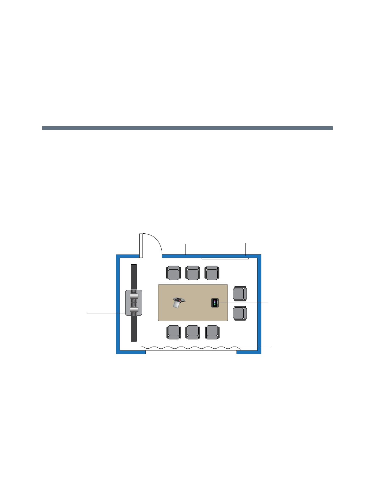
Room Integration
Polycom HDX
Acoustic Panels
Acoustic Quality
Drapes
Whiteboard
Microphone Array
Flat Panel
Monitor 1
Flat Panel
Monitor 2
Polycom HDX
Media Center
with 42” displays and
Polycom EagleEye
Director
Polycom
To u ch
Control
Setting Up a Room for Video Conferencing
For detailed information about setting up a r oom fo r vide o con fere ncing, refer to Room Design and Layout.
Room Layout Examples
Use the following diagrams as examples for setting up a conference room with Polycom HDX systems.
Polycom recommends that you contract an experienced contractor to ensure all the components operate
as a single cohesive system.
Small Conference Room
Polycom, Inc. 1
Page 20
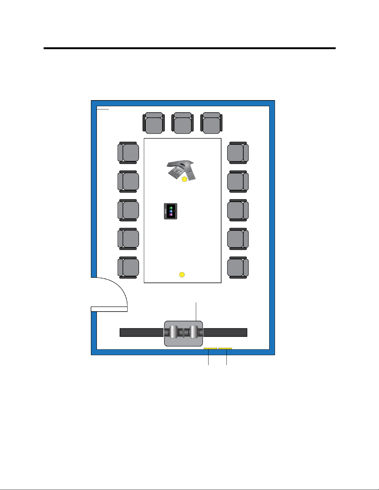
Integrator’s Reference Manual for Polycom HDX Systems Room Integration
Ceiling
Power Outlets
50”
50”
Polycom EagleEye
Acoustic Panels
Monitor 1
Monitor 2
Polycom HDX
Microphone
Director
Executive Collection
Polycom SoundStation®
IP 7000 Phone
Polycom Touch Control
Ceiling
Microphone
Network Outlets
Large Conference Room: Option 1
Large Conference Room: Option 2
Polycom, Inc. 2
Page 21
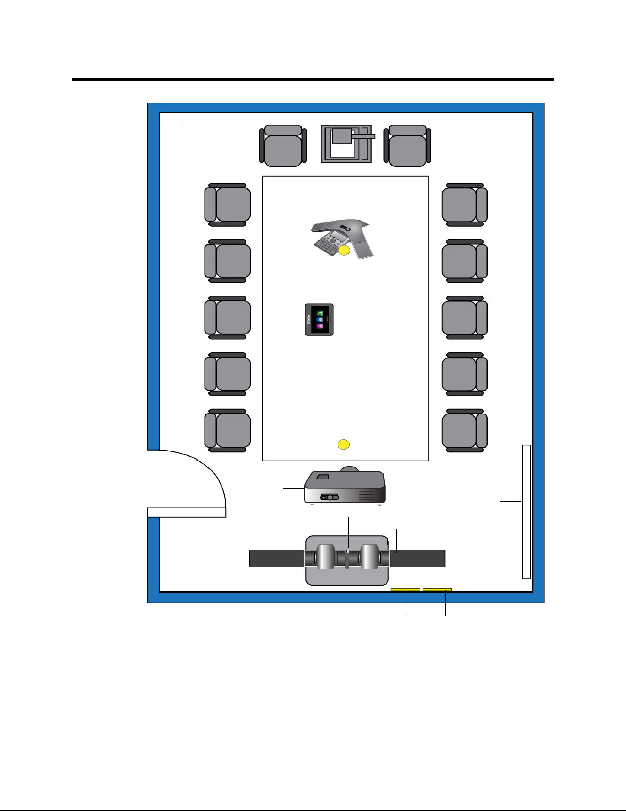
Integrator’s Reference Manual for Polycom HDX Systems Room Integration
Document Camera
Ceiling
50”
Polycom EagleEye
Acoustic Panels
Single Display
Microphone
Director
Polycom SoundStation®
IP 7000 Phone
Polycom Touch
Control
Power Outlet s
Network Outlets
Polycom HDX
Media Center
Ceiling
Microphone
Whiteboard
Projector
with Polycom
UC Board™
Sensor
Polycom, Inc. 3
Page 22
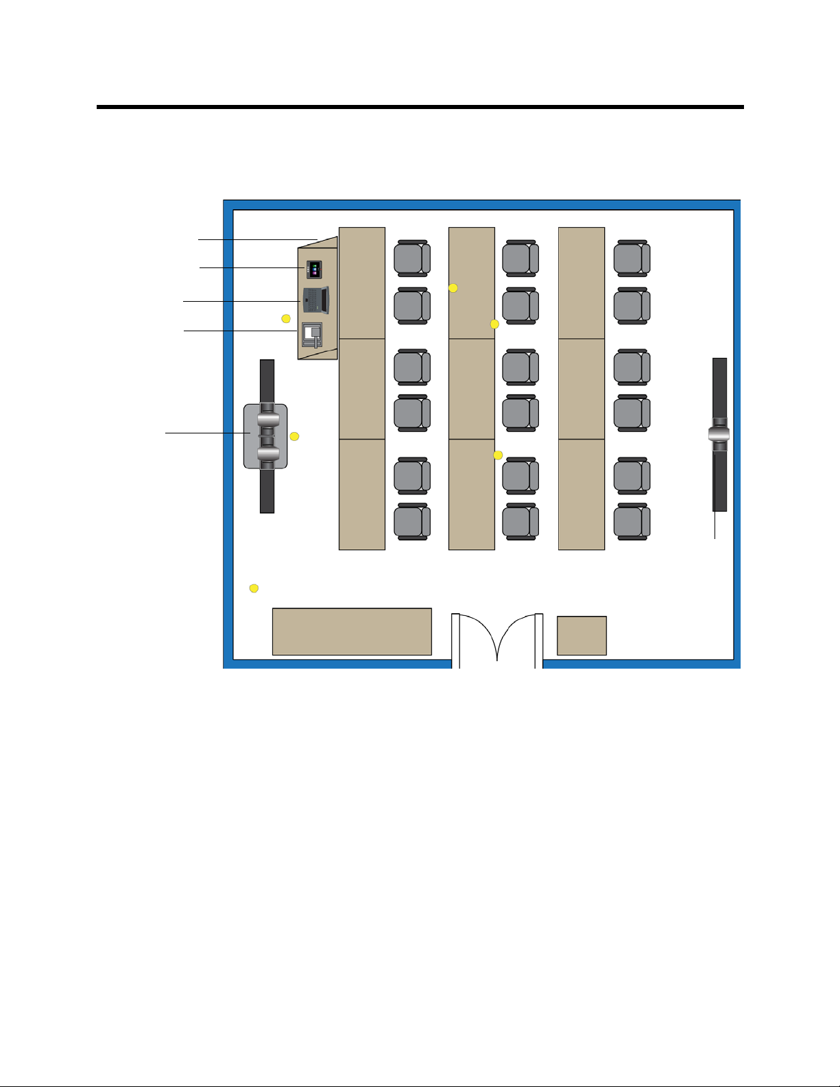
Integrator’s Reference Manual for Polycom HDX Systems Room Integration
Computer
Document
Monitor 1
Monitor for
Polycom
Camera 2
Polycom
Monitor 2
VGA Out
Camera
HDX system
with EagleEye
HD camera
and Polycom
SoundStructure™
mixer
Wall-mounted display
with EagleEye
Director establishing
shot devices
To u ch
Control
Teacher’s Podium
= Ceiling Microphone
Classroom
Setting Up the Room for Polycom People On Content™
For the best results, follow these guidelines for setting up Polycom People On Content™:
● Use the Polycom EagleEye HD camera with Polycom HDX 9000 series and Polycom HDX 8000
series systems. Polycom recommends using a Polycom EagleEye II, Polycom EagleEye III, Polycom
EagleEye HD or Polycom EagleEye HD 1080 camera with People on Content. If you are using a
Polycom EagleEye 1080 or Polycom EagleEye View camera, activating People on Content
automatically reduces the resolution to 720p.
● Create a flat, consistent background color using a screen or matte-finish pain t in green or blue. Make
sure the background has no shadows or glare.
● Make sure that the background and the prese n te r ar e well lit. Fo r example, use a minimum of two
250 W halogen lights on the background and one on the presenter.
● Experiment with different room and lighting arrangements until the best results are achieved.
Polycom, Inc. 4
Page 23
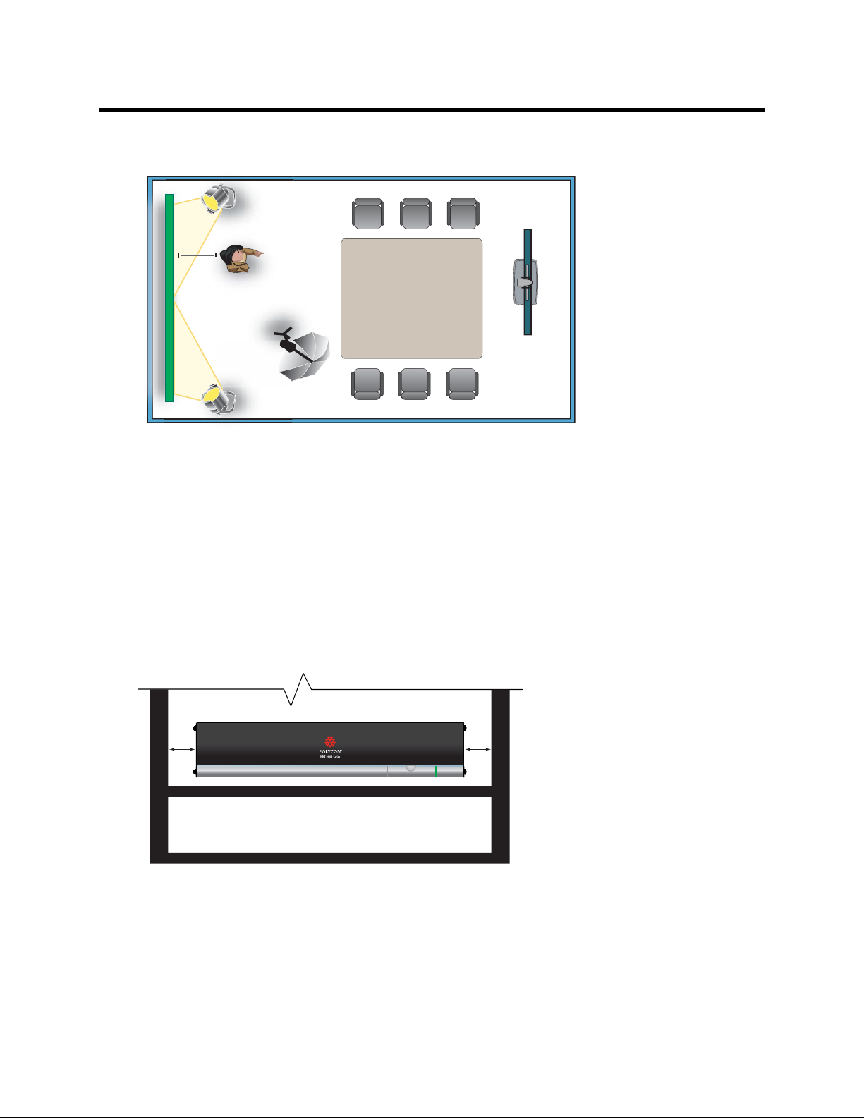
Integrator’s Reference Manual for Polycom HDX Systems Room Integration
3 ft
250 W
250 W
250 W
Polycom HDX
system and
EagleEye HD
camera
2”
2”
You can find more information about configuring and using People On Content in the User’s Guide for
Polycom HDX Systems and in the Knowledge Base on the Polycom web site.
Polycom HDX Installation Precautions
If you place the Polycom HDX series system in a cart or credenza, ensure that there is proper ventilation
for maintaining an ambient temperature of 40°C or lower.
Polycom HDX 6000, 7000, and 8000 series systems can be rack mounted on a Polycom shelf. Please refer
to the Polycom price book and part number 2215-28283-001.
Polycom recommends ventilation gaps of at least 2 inches (50.80 mm) on the left and rig ht of the system
with appropriate access to fresh air.
Polycom, Inc. 5
Page 24
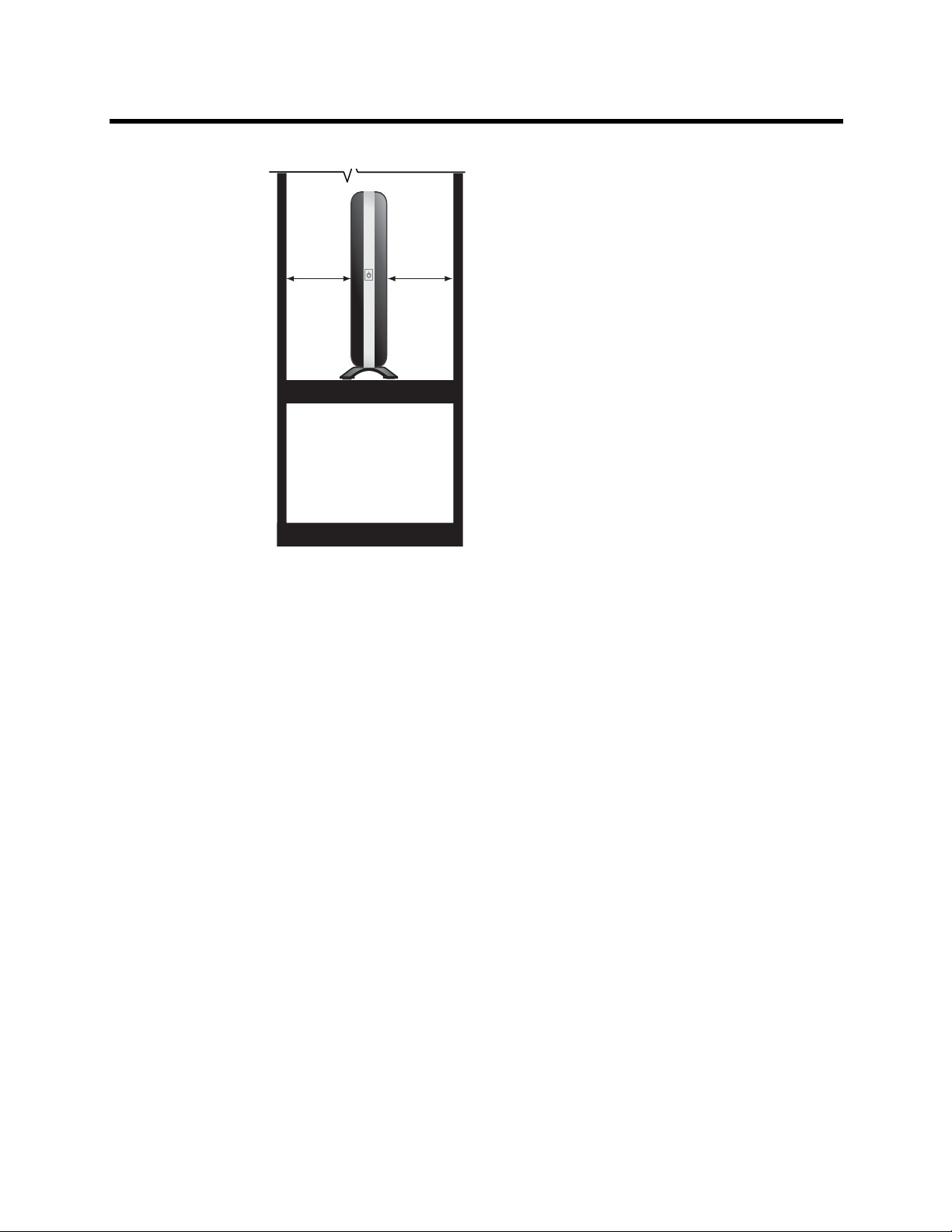
Integrator’s Reference Manual for Polycom HDX Systems Room Integration
2” 2”
Polycom, Inc. 6
Page 25
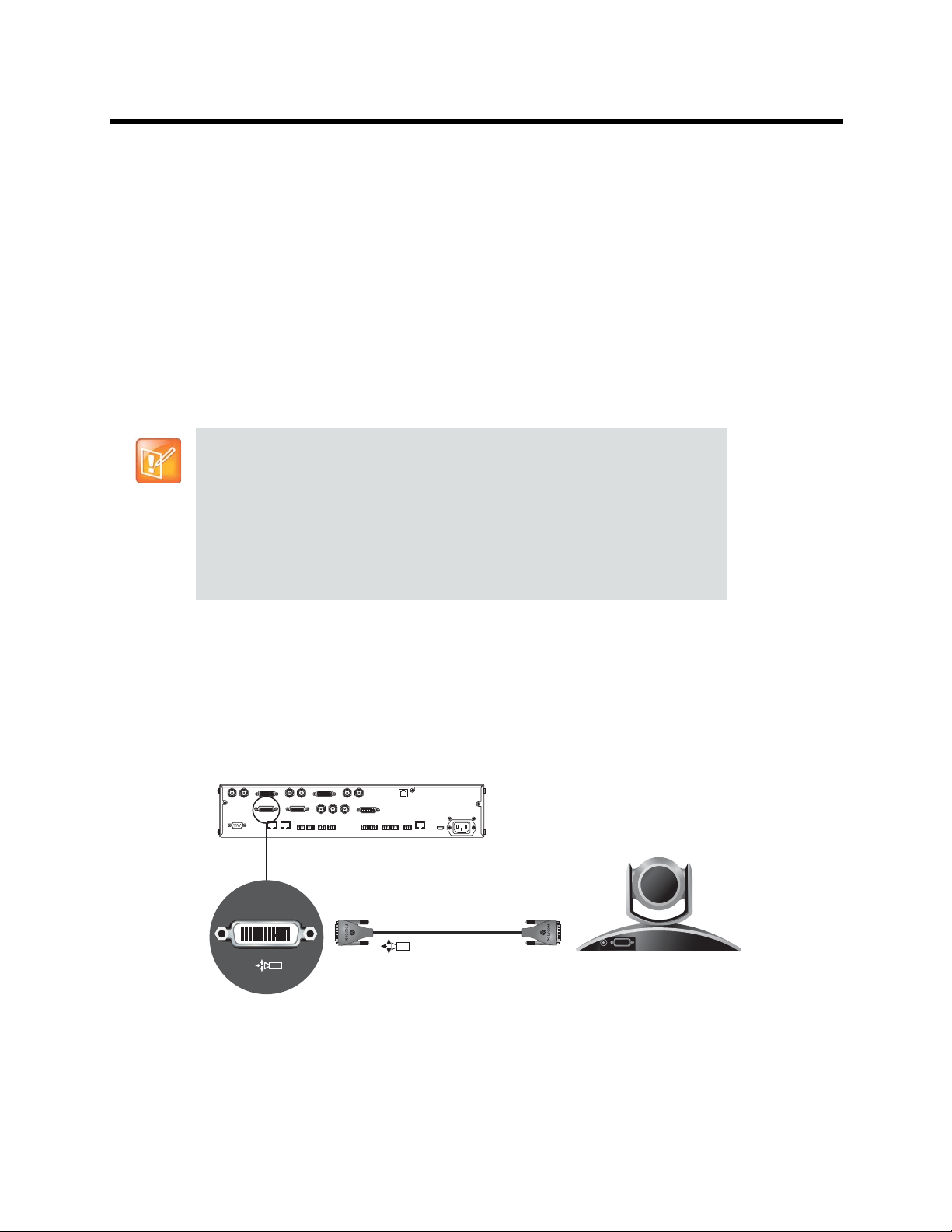
Integrator’s Reference Manual for Polycom HDX Systems Room Integration
1
1
Integrating Video
The following sections describe how to connect cameras to Polycom HDX systems. After you connect a
camera to a Polycom HDX system, refer to the Administrator’s Guide for Polycom HDX Systems for
information about configuring the camera options in the user interface.
Connecting Polycom Cameras
You can connect Polycom HDX systems to a Polycom EagleEye 1080, Polycom EagleEye HD, Polycom
EagleEye View, Polycom EagleEye II, Polycom EagleEye III, Polycom EagleEye Director,
Polycom PowerCam™, or PowerCam Plus or camera from Polycom, or to other supported cameras. Refer
to the release notes for the software release installed on the Polycom HDX system for a list of supported
PTZ cameras.
Points to Note about Polycom Cameras:
• The Polycom EagleEye HD connection diagrams can be applied to Polycom
EagleEye II cameras on Polycom HDX 9006 systems only. The diagrams can
also be applied to EagleEye III cameras on all Polycom HDX 9000 series
systems.
• Polycom HDX 6000 series, Polycom HDX 7000 series, and Polycom HDX 8000
series systems must be connected to one of the Polycom EagleEye cameras to
receive signals from the remote control. Point the remote control at the camera
to control those Polycom HDX systems.
Polycom EagleEye HD Camera as the Main Camera up to 30 ft Away
You can connect a Polycom EagleEye HD camera (part number 8200-23600-001
8200-23610-001, 8200-08270-xxx, or 8200-08260-xxx) to a Polycom HDX 9000 Series system
as the main camera using:
● HDCI Analog Camera Cable on page 54.
Polycom, Inc. 7
Page 26
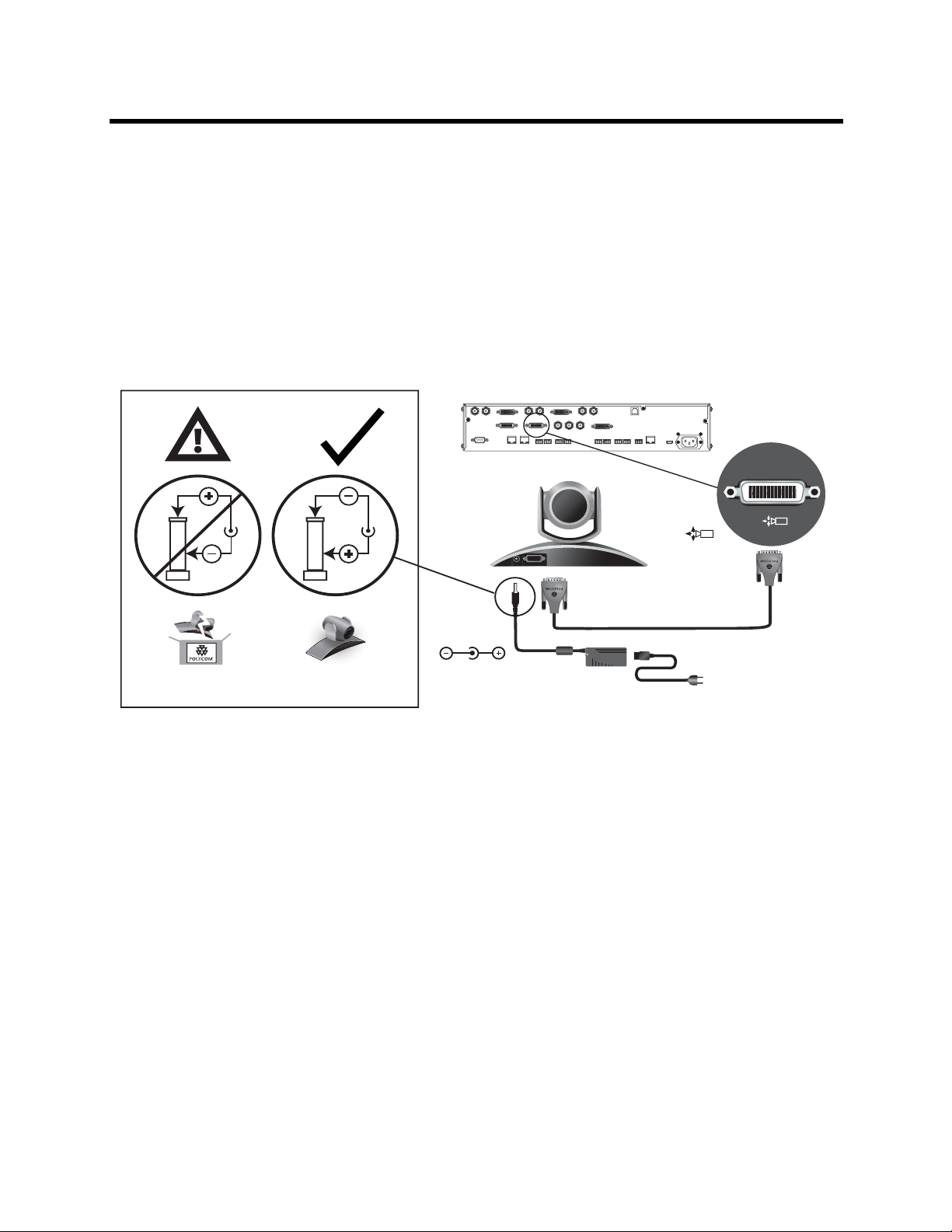
Integrator’s Reference Manual for Polycom HDX Systems Room Integration
2
2
DC IN 12V
Use Polycom Power Supply Only
Part Number: 1465-52733-040
Polycom EagleEye HD Camera as the Second Camera up to 30 ft Away
You can connect a Polycom EagleEye HD camera (part number 8200-23600-001,
8200-23610-001, 8200-08270-xxx, or 8200-08260-xxx) to a Polycom HDX 9000 Series system
as the second camera using:
● HDCI Analog Camera Cable on page 54.
● Power supply. Use only the approved power supply from Polycom (part number 1465-52748-040).
Do not exceed 12 Volts at 3 Amps. Verify the polarity of the power supply as shown on the Polycom
camera next to the power supply input.
Polycom, Inc. 8
Page 27
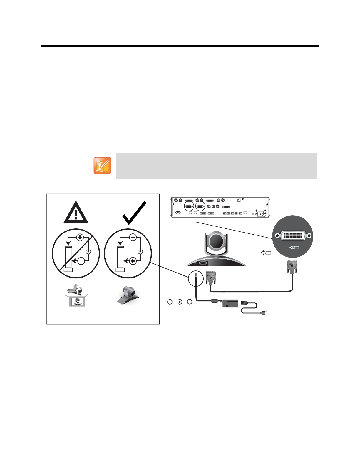
Integrator’s Reference Manual for Polycom HDX Systems Room Integration
50 ft or 100 ft
DC IN 12V
Use Polycom Power Supply Only
Part Number: 1465-52733-040
Polycom EagleEye HD Camera as the Main or Second Camera up to 100 ft Away
T o connect a Polycom Eagle Eye HD camera (p art number 8200-23600-001 82 00-23610-001,
8200-08270-xxx, 8200-08260-xxx, or 7200-25689-xxx) to a Polycom HDX 9000 Series system
more than 30 ft away:
Option 1
● HDCI Analog Camera Cable on page 54.
● Power supply. Use only the approved power supply from Polycom (part number 1465-52748-040).
Do not exceed 12 Volts at 3 Amps. Verify the polarity of the power supply as shown on the Polycom
camera next to the power supply input.
Polycom recommends this configuration when a custom cable length is not
required.
Option 2
● A—Two HDCI Camera Break-Out Cable on page 57.
● B—Coaxial analog video cables.
● C—DB-9 serial cable.
● Power supply. Use only the approved power supply from Polycom (part number 1465-52748-040).
Do not exceed 12 Volts at 3 Amps. Verify the polarity of the power supply as shown on the Polycom
camera next to the power supply input.
Polycom, Inc. 9
Page 28
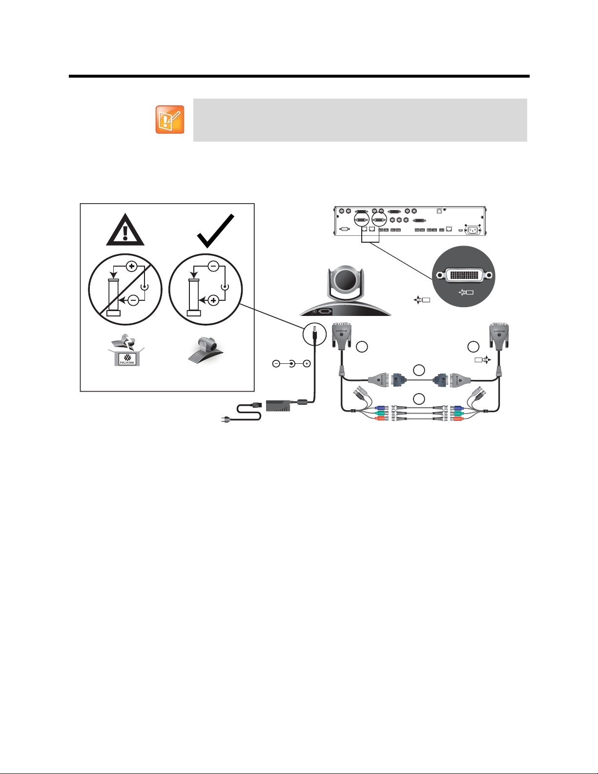
Integrator’s Reference Manual for Polycom HDX Systems Room Integration
Optional, up to 100 ft
A A
B
C
DC IN 12V
Use Polycom Power Supply Only
Part Number: 1465-52733-040
Polycom recommends this configuration when a custom cable length is required.
The BNC and serial cables can be built to custom lengths.
Polycom, Inc. 10
Page 29
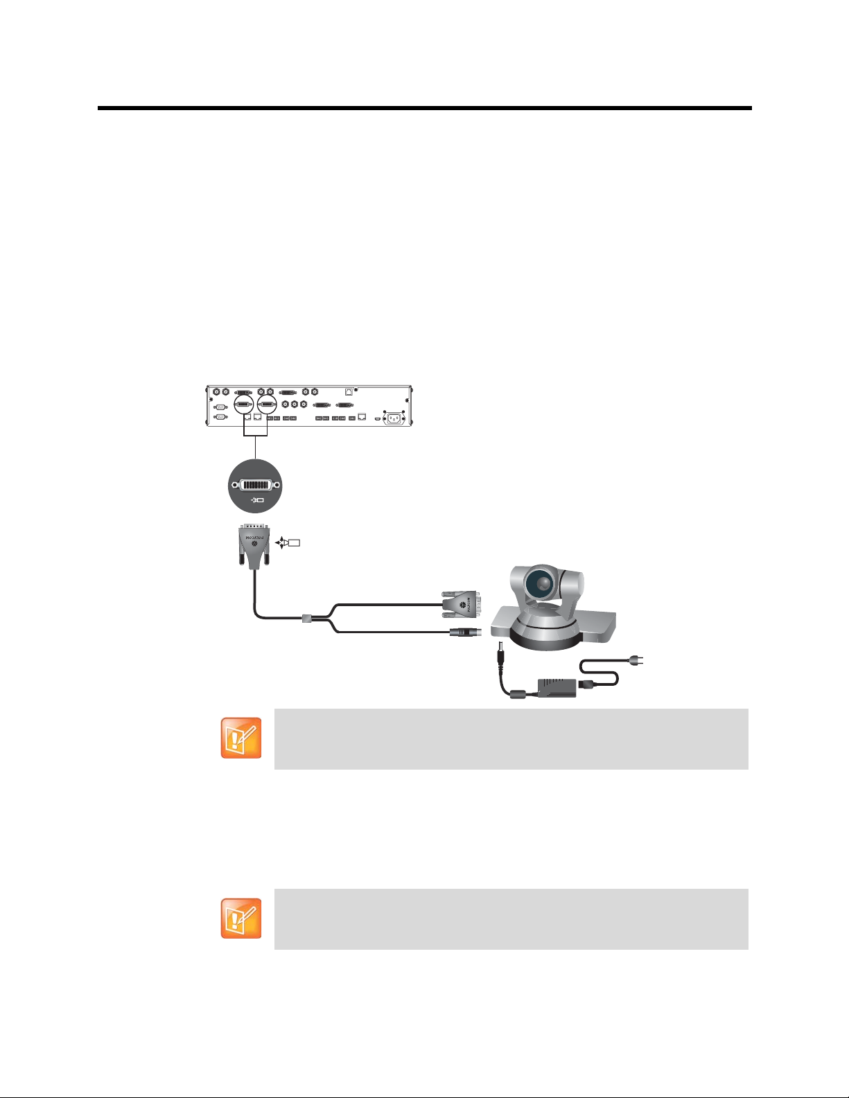
Integrator’s Reference Manual for Polycom HDX Systems Room Integration
Polycom EagleEye 1080 or Sony EVI-HD1 PTZ as the Main or Second Camera
You can connect a Polycom EagleEye 1080 or Sony EVI-HD1 PTZ camera to a Polycom
HDX 9000 Seriessystem as the main camera using:
Option 1
● HDCI Polycom EagleEye 1080 Camera Cable on page 61 (this cable is compatible with the Sony
EVI-HD1 PTZ camera).
● Power supply. Use only the approved power supply from Polycom (part number 1465-52748-040).
Do not exceed 12 Volts at 3 Amps. Verify the polarity of the power supply as shown on the Polycom
camera next to the power supply input.
Polycom recommends this configuration when a custom cable length is required.
Option 2
● A— HDCI Sony VISCA Adapter Cable on page 65.
● B—VGA cable.
● C—VISCA cable.
Polycom recommends this configuration when a custom cable length is required.
Polycom, Inc. 11
Page 30
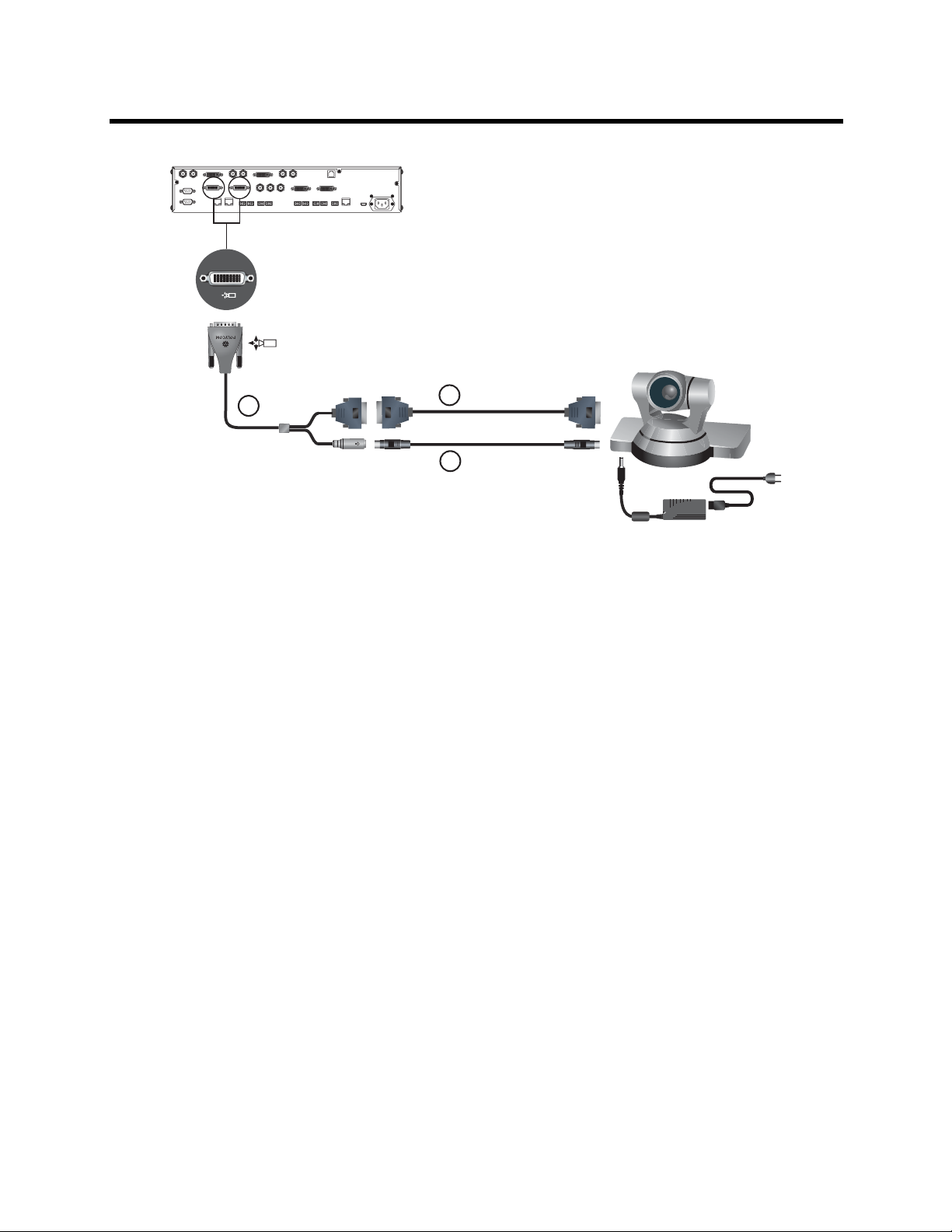
Integrator’s Reference Manual for Polycom HDX Systems Room Integration
Up to 100 ft
C
A
B
Up to 100 ft
Polycom EagleEye Director as the Main Camera or Second Camera
You can connect a Polycom EagleEye Director (part number 7200-82632-xxx,
7200-82631-xxx, or 2200-82559-xxx) to a Polycom HDX 9001, Polycom HDX 9002, or
Polycom HDX 9004 system as the main camera using:
● A—HDCI Analog Camera Cable on page 54.
Polycom, Inc. 12
Page 31

Integrator’s Reference Manual for Polycom HDX Systems Room Integration
A
B
● B—Polycom EagleEye Director Audio Feedback Phoenix to Phoenix Cable on page 97.
PowerCam as the Main Camera up to 10 ft Away
You can connect a PowerCam (part number 2215-50370-001) to a Polycom HDX 9001,
Polycom HDX 9002, or Polycom HDX 9004 system as the main camera up to 10 ft away
using:
● A—PowerCam Primary Camera Cable on page 68.
● B— HDCI PowerCam Plus Adapter Cable on page 59.
A
1
1
PowerCam as the Second Camera
The following kits are available, which include the power supply, PowerCam Break-Out cable, 8-pin
mini-DIN to DB-9 cable, and S-Video cable:
B
Polycom, Inc. 13
Page 32

Integrator’s Reference Manual for Polycom HDX Systems Room Integration
2
2
A
B
C
D
● 7230-22231-001 (50 ft)
● 7230-22232-001 (100 ft)
You can connect a PowerCam (part number 2215-50370-001) to a Polycom HDX 9001,
Polycom HDX 9002, or Polycom HDX 9004 system as the second camera using:
● A— PowerCam Break-Out Cable on page 69.
● B— 8-pin mini-DIN to DB-9 on page 72.
● C— S-Video Cable on page 42.
● D— HDCI PowerCam Plus Adapter Cable on page 59.
● Power Supply (part number 1465-52748-040).
You can connect a PowerCam (part number 2215-50370-001) to a Polycom HDX 9001,
Polycom HDX 9002, or Polycom HDX 9004 system as the third camera using:
● A— PowerCam Break-Out Cable on page 69.
● B— 8-pin mini-DIN to DB-9 on page 72.
● C— S-Video Cable on page 42.
● D—BNC to S-Video Cable on page 43.
● Power Supply (part number 1465-52748-040).
Polycom, Inc. 14
Page 33

Integrator’s Reference Manual for Polycom HDX Systems Room Integration
A
B
C
D
IOIOIO
IOIOIO
If you connect a PTZ camera to a serial port, set RS-232 Mode to Camera PTZ on the Serial Ports screen.
YC
VCR/DVD
3
VCR/DVD
3
PowerCam Plus as the Main Camera up to 10 ft Away
Y ou can connect a PowerCam Plus (p art num ber 2215-50200-001) to a Polyc om HDX 9001,
Polycom HDX 9002, or Polycom HDX 9004 system as the main camera up to 10 ft away
using:
● A— PowerCam Primary Camera Cable on page 68.
● B— HDCI PowerCam Plus Adapter Cable on page 59.
Automatic camera tracking is not available when using the PowerCam Plus camera
with a Polycom HDX system.
Polycom, Inc. 15
Page 34

Integrator’s Reference Manual for Polycom HDX Systems Room Integration
B
A
2
2
A
B
1
1
PowerCam Plus as the Second Camera up to 10 ft Away
Y ou can connect a PowerCam Plus (p art num ber 2215-50200-001) to a Polyc om HDX 9001,
Polycom HDX 9002, or Polycom HDX 9004 system as the second camera up to 10 ft away
using:
● A— PowerCam Primary Camera Cable on page 68.
● B— HDCI PowerCam Plus Adapter Cable on page 59.
● Power Supply (part number 1465-52748-040).
Automatic camera tracking is not available when using the PowerCam Plus camera
with a Polycom HDX system.
Polycom, Inc. 16
Page 35

Integrator’s Reference Manual for Polycom HDX Systems Room Integration
Up to 100 ft
A
B
C
Connecting Sony and ELMO Cameras
Refer to the release notes for a list of supported Pan/Tilt/Zoom (PTZ) cameras.
Sony or ELMO PTZ as the Main or Second Camera
T o connect a Sony or ELMO PTZ camera to a Polycom HDX 9000 Series system as the m ain
or second camera:
You can connect a Sony or ELMO PTZ camera to a Polycom HDX system using:
● A— HDCI Sony VISCA Adapter Cable on page 65.
● B— S-Video Cable on page 42.
● C—Sony VISCA cable.
Sony BRC-H700 PTZ
To connect a Sony BRC-H700 PTZ camera to a Polycom HDX 9000 Series system:
You can connect a Sony BRC-H700 PTZ camera to a Polycom HDX system using:
● A— DVI to VGA Monitor Cable on page 47.
● B— 8-pin mini-DIN to DB-9 on page 72.
● C—VGA extension cable.
Polycom, Inc. 17
To provide XGA output (1024x768), you must install the optional Sony HFBK-XG1
card into the slot on the back of the Sony BRC-H700 PTZ camera.
Page 36

Integrator’s Reference Manual for Polycom HDX Systems Room Integration
Up to 100 ft
A
B
C
IOIOIO
IOIOIO
Another option is to use a VGA cable for cable C and to use a VGA/DVI-A adapter
(part number 1517-52689-001) for cable A. The VGA/DVI-A adapter is a solid
overmolded adapter that connects to the Polycom HDX 9000 Series system side of
cable C and adapts from cable C’s VGA connector to a DVI-A connector to plug into
the Polycom HDX 9000 Series system.
Polycom, Inc. 18
Page 37

Integrator’s Reference Manual for Polycom HDX Systems Room Integration
Connecting Vaddio and Canon Cameras
Refer to the release notes for a list of supported Pan/Tilt/Zoom (PTZ) cameras.
Vaddio or Canon PTZ as the Main or Second Camera
To connect a Vaddio or Canon PTZ camera to a Polycom HDX 9000 Series system as the
main or second camera:
You can connect a Vaddio 70, Vaddio 100, or Canon (with VISCA cable shoe) PTZ camera to a Polycom
HDX system using:
● A— HDCI VISCA Adapter Cable on page 60.
● B—DB-9 serial cable.
● C—S-Video Cable on page 42.
B
Up to 100 ft
A
Up to 100 ft
C
A separate power supply is required regardless of which connector is used on the
HDX 9000 Series back panel.
Vaddio 300 PTZ as the Main or Second Camera
T o connect a Vaddio 300 PTZ camera to a Polycom HDX 9000 Series system as the main or
second camera:
You can connect a Vaddio 300 PTZ camera to a Polycom HDX system using:
● A—HDCI VISCA Adapter Cable on page 60.
● B—DB-9 serial cable.
Polycom, Inc. 19
Page 38

Integrator’s Reference Manual for Polycom HDX Systems Room Integration
Up to 100 ft
Quick-Connect
Box
RJ45
A
B
C
● C—S-Video Cable on page 42.
Note: For situations that require extraordinary cable lengths, CAT5 extension kits for camera video, power,
and control are available from third-party vendors.
Polycom, Inc. 20
Page 39

Integrator’s Reference Manual for Polycom HDX Systems Room Integration
4
2
1
100-240VAC 50/60Hz 4A
LAN
IR
3
VCR/DVD
1
4
Y
C
3
VCR/DVD
Y
C
VCR/DVD
3
3
VCR/DVD
1
2
Y
C
1
1
IOIOIO
Y C
1
A
B
C
Integrating Audio and Content
Connecting a Computer to a Polycom HDX 9000 Series System
You can connect Polycom HDX 9000 series systems to a computer.
To connect a computer to a Polycom HDX 9001 or Polycom HDX 9002 system:
Option 1
Connect a Polycom HDX 9001 or Polycom HDX 9002 system to a computer using
● A—DVI to VGA Monitor Cable on page 47.
● B—3.5 mm stereo to RCA adapter cable.
● C—Audio Adapter Cable on page 90.
When you connect a computer to a Polycom HDX 9001 or Polycom HDX 9002 as follows, audio is only
heard at the far site and may be heard even when video input 4 is not selected.
Option 2
T o hear audio at both the near site and the far site, us e a bypass mixer to connect a computer to the Polycom
HDX 9001 or Polycom HDX 9002 system as the following figure shows.
Polycom, Inc. 21
Page 40

Integrator’s Reference Manual for Polycom HDX Systems Room Integration
4
Y
YC
1
IOIOIO
1
Y
C
2
1
2
Y
3
VCR/DVD
1
3
C
VCR/DVD
3
C
VCR/DVD
4
VCR/DVD
IR
3
1
LAN
100-240VAC 50/60Hz 4A
1
1
To connect a computer to a Polycom HDX 9004 system:
Connect a Polycom HDX 9004 system to a computer using
● A—DVI to VGA Monitor Cable on page 47.
● B—3.5 mm stereo to RCA adapter cable.
● C—Audio Adapter Cable on page 90 (Polycom HDX 9004, Polycom HDX 9002, and Polycom HDX
9001 systems only).
When you connect a computer to video input 4 and audio input 4 on a Po lycom HDX 9004 as follows, audio
from input 4 is muted unless video input 4 is selected as a video source.
A
4
Y
Y
C
2
2
1
C
Y
3
VCR/DVD
1
3
4
B
Y C
1
2
IOIOIO
1
To connect a computer to a Polycom HDX 9006 system:
Connect a Polycom HDX 9006 system to a computer using:
● A—DVI to VGA Monitor Cable on page 47.
● B—3.5 mm stereo to dual 3-pin Phoenix connectors cable.
Polycom, Inc. 22
C
VCR/DVD
4
3
C
VCR/DVD
4
5
VCR/DVD
4
1
IR
3
LAN
100-240VAC 50/60Hz 4A
Page 41

Integrator’s Reference Manual for Polycom HDX Systems Room Integration
When you connect a computer to video input 4 and audio input 4 on a Polycom HDX 9006 system as follows,
audio from input 4 is muted unless video input 4 is selected as a video source.
Connecting a Vortex® Mixer to a Polycom HDX 9000 Series System
Polycom strongly recommends using Polycom InstantDesigner™ to get started with
your Vortex® mixer integration. InstantDesigner resolves many common issues
with connections and configuration settings.
To use a Polycom HDX system with audio input from a Vortex mixer, set the Input
Type to Line Input and disable Echo Canceller.
Connect a Polycom HDX system to the Vortex mixer using:
● Vortex Cable on page 92.
Y
YC
1
2
IOIOIO
1
IOIOIO
Y
C
2
2
1
Y
3
VCR/DVD
1
3
1
C
VCR/DVD
3
C
VCR/DVD
4
4
1
B
A
A
B
4
5
VCR/DVD
IR
3
100-240VAC 50/60Hz 4A
LAN
1
Polycom, Inc. 23
Page 42

Integrator’s Reference Manual for Polycom HDX Systems Room Integration
2
1
100-240VAC 50/60Hz 4A
LAN
IR
5
4
3
VCR/DVD
1
4
Y
C
3
VCR/DVD
Y
C
VCR/DVD
3
4
3
VCR/DVD
1
2
Y
C
1
2
1
IOIOIO
YC
CAV 052-09
z
H
06/
0
5
PIN 2: TXD
PIN 3: RXD
PIN 5: GROUND
PIN 7: CTS
PIN 8: RTS
LAN
C-LINK2
OBAM IR
RS-232
REMOTE CONTROL 2
REMOTE CONTROL 1
IN OUT
1 2345678910111213141516
12345678910111213141516
S
TUPTUO
ST
UP
N
I
SoundStructure C16
TM
12V
CAV 052-09
z
H
0
6/
0
5
PIN 2: TXD
PIN 3: RXD
PIN 5: GROUND
PIN 7: CTS
PIN 8: RTS
LAN
C-LINK2
OBAM IR
RS-232
REMOTE CONTROL 2
REMOTE CONTROL 1
IN OUT
1 2345678910111213141516
12345678910111213141516
S
TUPTUO
ST
UP
N
I
SoundStructure C16
TM
12V
4
4
VCR/DVD
3
VCR/DVD
3
AUX
Connecting a Polycom SoundStructure C-Series Mixer to a Polycom HDX System
Connect a Polycom HDX system to the Polycom SoundStructure C-Series mixer using Polycom HDX
Microphone Array Host Cable.
Polycom HDX 9000 system:
Polycom HDX 8000 system:
Polycom, Inc. 24
Page 43

Integrator’s Reference Manual for Polycom HDX Systems Room Integration
CAV 052-09
z
H
0
6/
0
5
PIN 2: TXD
PIN 3: RXD
PIN 5: GROUND
PIN 7: CTS
PIN 8: RTS
LAN
C-LINK2
OBAM IR
RS-232
REMOTE CONTROL 2
REMOTE CONTROL 1
IN OUT
1 2 3 4 5 6 7 8 9 10 11 12 13 14 15 16
1 2 3 4 5 6 7 8 9 10 11 12 13 14 15 16
S
TUPTUO
ST
UP
N
I
SoundStructure C16
TM
12V
Polycom HDX 7000 system:
5
0
6/
0
H
z
CAV 052-09
LAN
C-LINK2
Polycom HDX 6000 system:
IN OUT
OBAM IR
PIN 2: TXD
PIN 3: RXD
PIN 5: GROUND
PIN 7: CTS
PIN 8: RTS
RS-232
12V
1 2 3 4 5 6 7 8 9 10 11 12 13 14 15 16
REMOTE CONTROL 1
1 2 3 4 5 6 7 8 9 10 11 12 13 14 15 16
REMOTE CONTROL 2
SoundStructure C16
TUPTUO
S
I
N
UP
ST
TM
Polycom, Inc. 25
Page 44

Integrator’s Reference Manual for Polycom HDX Systems Room Integration
Points to Note:
• The microphone input of the Polycom HDX Series system can support one
connection to SoundStructure C-Series mixers. For more information about using
the SoundStructure C-Series mixer with a Polycom HDX system, refer to the
SoundStructure C-Series documentation on the Polycom web site.
You cannot connect both a SoundStructure C-Series mixer and a SoundStation
IP 7000 phone to the Polycom HDX 9000 Series system at the same time.
• If the EagleEye Director device is connected to a Polycom HDX system that is
connected to a SoundStructure C-Series mixer (or echo cancellers, sound
mixers, or other external devices) and the SoundStructure C-Series mixer is
connected to the room audio playback system, the EagleEye Director's audio
feedback cable (Polycom EagleEye Director Audio Feedback Phoenix to
Phoenix Cable) must connect to the balanced audio output connector of
SoundStructure. The room audio playback system must connect through the
EagleEye Director's audio feedback cable to the SoundStructure C-Series mixer.
Polycom, Inc. 26
Page 45

Cables
T568B Pair
This section includes information about cables that can b e used with a Polyco m HDX system. Please no te
that drawings and part numbers are provided fo r reference only. Compliance information is provided for the
Restriction of certain Hazardous Substances Directive (RoHS).
Network Cables
CAT 5e LAN Cable
This cable connects a Polycom HDX system to the LAN. It has orange RJ-45 connectors on both ends. It
meets category 5e requirements and is wired according to EIA/TIA-568B. The maximum approved length
for this cable is 100 ft (30 m) on an 802 network.
Length Part Number RoHS Compliant
12 ft (3.6 m) 2457-23537-001 Yes
T568B Pair
Drawings and part numbers are provided for reference only. Polycom claims no
responsibility or liability for the quality, performance, or reliability of cables based on
these reference drawings, other than cables provided by Polycom. Contact your
Polycom distributor or Polycom Custom/Vertical Products to order cables that meet
the appropriate manufacturing tolerances, quality, and performance parameters for
your application.
Polycom, Inc. 27
Page 46

Integrator’s Reference Manual for Polycom HDX Systems Cables
CONN. RJ-45
( x2 )
12 FEET +/- 3"
P2
P1
PIN 8
PIN 8
11
22
33
44
55
66
77
88
PIN#PIN
#
P2P1
LAN Cable
This cable connects a Polycom HDX to the LAN. It has orange RJ-45 connectors on both ends and is used
with all systems. The maximum approved length for this cable is 100 ft (30 m).
Length Part Number RoHS Compliant
12 ft (3.6 m) 2457-08343-001 Yes
Drawings and part numbers are provided for reference only. Polycom claims no
responsibility or liability for the quality, performance, or reliability of cables based on
these reference drawings, other than cables provided by Polycom. Contact your
Polycom distributor or Polycom Custom/Vertical Products to order cables that meet
the appropriate manufacturing tolerances, quality, and performance parameters for
your application.
Polycom, Inc. 28
Page 47

Integrator’s Reference Manual for Polycom HDX Systems Cables
Polycom Touch Control LAN Cable
This cable connects a Polycom Touch Control device to the LAN.
Length Part Number RoHS Compliant
25 ft (7.62 m) 2457-26994-001 Yes
Drawings and part numbers are provided for reference only. Polycom claims no
responsibility or liability for the quality, performance, or reliability of cables based on
these reference drawings, other than cables provided by Polycom. Contact your
Polycom distributor or Polycom Custom/Vertical Products to order cables that meet
the appropriate manufacturing tolerances, quality, and performance parameters for
your application.
Polycom, Inc. 29
Page 48

Integrator’s Reference Manual for Polycom HDX Systems Cables
Pin 8
Pin 1
Signal Name
Receive Ring
Receive Tip
No Connection
Transmit Ring
Transmit Tip
No Connection
No Connection
No Connection
Pin
1
2
3
4
5
6
7
8
ISDN Cable
This cable connects a Polycom HDX system to a BRI or PRI line. It has clear RJ-45 connecto rs on bo th
ends and is used with all Polycom HDX systems that have ISDN capability. The maximum approved length
for this cable is 50 ft (15 m).
Length Part Number RoHS Compliant
20 ft (6.6 m) 2457-08548-001 Yes
PRI Pin Assignments
The following illustration and table show the pin assignments for the PRI port on the Polycom HDX system.
Polycom, Inc. 30
Page 49

Integrator’s Reference Manual for Polycom HDX Systems Cables
Drawings and part numbers are provided for reference only. Polycom claims no
responsibility or liability for the quality, performance, or reliability of cables based on
these reference drawings, other than cables provided by Polycom. Contact your
Polycom distributor or Polycom Custom/Vertical Products to order cables that meet
the appropriate manufacturing tolerances, quality, and performance parameters for
your application.
Polycom, Inc. 31
Page 50

Integrator’s Reference Manual for Polycom HDX Systems Cables
Analog Telephone (POTS) Cable
This cable connects a Polycom HDX system to an analog telephone line. It has pink RJ-11 connectors on
both ends. The maximum approved length for this cable is 100 ft (30 m).
Length Part Number RoHS Compliant
12 ft (3.6 m) 2457-20071-001 Yes
WIRING DIAGRAM:
AWG P1 P2 COLOR
24 2 2 BLACK
24 3 3 YELLOW
24 4 4 GREEN
24 5 5 RED
Drawings and part numbers are provided for reference only. Polycom claims no
responsibility or liability for the quality, performance, or reliability of cables based on
these reference drawings, other than cables provided by Polycom. Contact your
Polycom distributor or Polycom Custom/Vertical Products to order cables that meet
the appropriate manufacturing tolerances, quality, and performance parameters for
your application.
Polycom, Inc. 32
Page 51

Integrator’s Reference Manual for Polycom HDX Systems Cables
Notes (direction from V.35 module (DTE))
68 pin Signal Name Signal Type From card Function V.35 RS530-DB25 RS4449-DB37 RS366-DB25
Shield V.35/RS449/RS530 A 19 7,18,19#
12 Receive Data A Differential in V.35/RS449/RS530 R 3 6
11 Receive Data B Differential in V.35/RS449/RS530 T 16 24
10 Send Timing A Differential in V.35/RS449/RS530 Y 15 5
9 Send Timing B Differential in V.35/RS449/RS530 AA 12 23
29 Data Set Ready (DSR) Single Ended in V.35 E
28 Request To Send (RTS) Single Ended out V.35 C
27 Data Terminal Ready (DTR) Single Ended out V.35 H
34 Digit Present (DPR) Single Ended out RS366 2
24 Abandon Call/Retry (ACR) Single Ended in RS366 3
32 Call Request (CRQ) Single Ended out RS366 4
26 Present Next Digit (PND) Single Ended in RS366 5
21 Data Line Occupied (DLO) Single Ended in RS366 22
14 Receive Timing A Differential in V.35/RS449/RS530 V 17 8
13 Receive Timing B Differential in V.35/RS449/RS530 X 9 26
8 Terminal Timing A Differential out V.35/RS449/RS530 U 24 17
7 Terminal Timing B Differential out V.35/RS449/RS530 W 11 35
15 Request To Send (RTS) A Differential out RS449/RS530 4 7
16 Request To Send (RTS) B Differential out RS449/RS530 19 25
35** Receive Common Gnd RS449 20
20 BCD Dial Digit Bit 1 (NB1) Single Ended out RS366 14
19 BCD Dial Digit Bit 2 (NB2) Single Ended out RS366 15
23 BCD Dial Digit Bit 4 (NB4) Single Ended out RS366 16
25 BCD Dial Digit Bit 8 (NB8) Single Ended out RS366 17
2** Signal Ground Gnd V.35/RS366 B 7,18,19
6 Send Data A Differential out V.35/RS449/RS530 P 2 4
5 Send Data B Differential out V.35/RS449/RS530 S 14 22
reserved (Ascend select line)
63 Clear To Send (CTS) A Differential in RS449/RS530 5 9
64 Clear To Send (CTS) B Differential in RS449/RS530 13 27
61 Data Mode (DM-DSR) A Differential in RS449/RS530 6 11
62 Data Mode (DM-DSR) B Differential in RS449/RS530 22 29
65 Receiver Ready (RR-DCD) A Differential in RS449/RS530 8 13
66 Receiver Ready (RR-DCD) B Differential in RS449/RS530 10 31
4** Send Common Gnd RS530 7 37
33 Data Carrier Detect (DCD) Single Ended in V.35 F
18 Terminal Ready (TR-DTR) A Differential out RS449/RS530 20 12
17 Terminal Ready (TR-DTR) B Differential out RS449/RS530 23 30
3 V.35 Cable Connected ground to indicate a V.35 cable is attached 7,18,19*
1 RS449 Cable Connected ground to indicate a RS449 cable is attached 7,18,19^#
22
Distant Station Connected (DSC)
Single Ended in RS366 13
30 Clear To Send (CTS) Single Ended in V.35 D
31
Ring Indicate (RI) (Incoming Call)
Single Ended in V.35/RS449 J 15
reserved (Ascend select line)
68 LOS A Differential out RS530 crypto 18 3
67 LOS B Differential out RS530 crypto 21 21
* For V.35, connect pin 3 of 68 pin connector to ground
^For RS449, connect pin 1 of 68 pin connector to ground
#For RS530, connect pins 1 and 3 of 68 pin connector to ground
** Gnd pins are 2,4, 35-60
Peripheral Link
V.35 HD-68 Pinout
V.35/RS-449/RS-530 Serial Adapter
This adapter is used when connecting a Polycom HDX system to other third-party network equipment. It
adapts the 68-pin interface to an industry standard 44-pin interface used by some network interface
equipment. It is used with Polycom HDX systems that have a V.35/RS-449/RS-530 serial network interface
card (NIC) installed.
Length Part Number RoHS Compliant
6 in (15.23 cm) 2457-21264-200 Yes
Polycom, Inc. 33
Page 52

Integrator’s Reference Manual for Polycom HDX Systems Cables
Drawings and part numbers are provided for reference only. Polycom claims no
responsibility or liability for the quality, performance, or reliability of cables based on
these reference drawings, other than cables provided by Polycom. Contact your
Polycom distributor or Polycom Custom/Vertical Products to order cables that meet
the appropriate manufacturing tolerances, quality, and performance parameters for
your application.
Polycom, Inc. 34
Page 53

Integrator’s Reference Manual for Polycom HDX Systems Cables
V.35 NIC Cable
This cable connects a Polycom HDX system to Ascend network equipment. It is used with the
V.35/RS-449/RS-530 Serial Adapter on page 33 to connect to network equipment that has the HD-44 pin
interface. It has HD-44 M connectors on both ends and is used with Polycom HDX systems that have a serial
network interface card (NIC) installed.
Length Part Number RoHS Compliant
5 ft (1.65 m) 2457-10608-200 Yes
Drawings and part numbers are provided for reference only. Polycom claims no
responsibility or liability for the quality, performance, or reliability of cables based on
these reference drawings, other than cables provided by Polycom. Contact your
Polycom distributor or Polycom Custom/Vertical Products to order cables that meet
the appropriate manufacturing tolerances, quality, and performance parameters for
your application.
Polycom, Inc. 35
Page 54

Integrator’s Reference Manual for Polycom HDX Systems Cables
V.35 and RS-366 Serial Cable
This cable connects a Polycom HDX system to third-party network equipment. It is used with the
V.35/RS-449/RS-530 Serial Adapter on page 33 to connect to network equipment that has a V.35/RS-366
interface. It is HD-44 M to “Y” Winchester 34M/RS-366 DB-25M and is used with Polycom HDX systems
that have a serial network interface card (NIC) installed.
Length Part Number RoHS Compliant
5 ft (1.65 m) 2457-10609-200 Yes
Drawings and part numbers are provided for reference only. Polycom claims no
responsibility or liability for the quality, performance, or reliability of cables based on
these reference drawings, other than cables provided by Polycom. Contact your
Polycom distributor or Polycom Custom/Vertical Products to order cables that meet
the appropriate manufacturing tolerances, quality, and performance parameters for
your application.
Polycom, Inc. 36
Page 55

Integrator’s Reference Manual for Polycom HDX Systems Cables
RS-449 and RS-366 Serial Cable
This cable connects a Polycom HDX system to third-party network equipment. It is used with the
V .35 /RS-449/RS-530 seri al adapter on p age V.35/RS-449/RS-530 Serial Adapter on page 33 to connect to
network equipment that has an RS-449/RS-366 interface. It is HD-44 M to “Y” RS-449 DB-37M/RS-366
DB-25M and is used with Polycom HDX systems that have a serial network interface card (NIC) installed.
Length Part Number RoHS Compliant
5 ft (1.65 m) 2457-10610-200 Yes
Polycom, Inc. 37
Page 56

Integrator’s Reference Manual for Polycom HDX Systems Cables
Drawings and part numbers are provided for reference only. Polycom claims no
responsibility or liability for the quality, performance, or reliability of cables based on
these reference drawings, other than cables provided by Polycom. Contact your
Polycom distributor or Polycom Custom/Vertical Products to order cables that meet
the appropriate manufacturing tolerances, quality, and performance parameters for
your application.
Polycom, Inc. 38
Page 57

Integrator’s Reference Manual for Polycom HDX Systems Cables
Peripheral Link V.35 HD-68 Pinout
Notes (direction from V.35 module (DTE))
68 pin Signal Name Signal Type From card Function RS530-DB25 RS366-DB25
Shield V.35/RS449/RS530 7,18,19#
12 Rece
ive Data A Differential in V.35/RS449/RS530 3
11 Receive Data B Differential in V.35/RS449/RS530 16
10 Send Timin
g A Differential in V.35/RS449/RS530 15
9 Send Timing B Differential in V.35/RS449/RS530 12
29 Data Set Ready (DS
R) Single Ended in V.35
28 Request To Send (RTS) Single Ended out V.35
27 Data Terminal Ready (DTR) Single Ended
out V.35
34 Digit Present (DPR) Single Ended out RS366 2
24 Abandon Call/Retry (ACR) Single Ended in RS366 3
32 Call
Request (CRQ) Single Ended out RS366 4
26 Present Next Digit (PND) Single Ended in RS366 5
21 Data Line Occupied
(DLO) Single Ended in RS366 22
14 Receive Timing A Differential in V.35/RS449/RS530 17
13 Receive Timing B Differ
ential in V.35/RS449/RS530 9
8 Terminal Timing A Differential out V.35/RS449/RS530 24
7 Terminal Timing B Differe
ntial out V.35/RS449/RS530 11
15 Request To Send (RTS) A Differential out RS449/RS530 4
16 Request To Send (RTS)
B Differential out RS449/RS530 19
35** Receive Common Gnd RS449
20 BCD Dial Digit Bit 1 (NB1) Single Ended out R
S366 14
19 BCD Dial Digit Bit 2 (NB2) Single Ended out RS366 15
23 BCD Dial Digit Bit 4 (NB4) Single Ended out
RS366 16
25 BCD Dial Digit Bit 8 (NB8) Single Ended out RS366 17
2** Signal Ground Gnd V.35/RS366 7,18,19
6 Send D
ata A Diff erential out V.35/RS449/RS530 2
5 Send Data B Differential out V.35/RS449/RS530 14
reserved (Ascend se
lect line)
63 Clear To Send (CTS) A Differential in RS449/RS530 5
64 Clear To Send (CTS) B Differential in RS449
/RS530 13
61 Data Mode (DM-DSR) A Differential in R S449/RS530 6
62 Data Mode (DM-DSR) B Differential in R S449/RS5
30 22
65 Receiver Ready (RR-DCD) A Differential in RS449/RS530 8
66 Receiver Ready (RR-DCD) B Differential in RS4
49/RS530 10
4** Send Common Gnd RS530 7
33 Data Carrier Detect (DCD) Single Ended in V.35
18 Terminal Ready (TR-DT
R) A Differential out RS449/RS530 20
17 Terminal Ready (TR-DTR) B Diff erential out RS449/RS530 23
3 V.35 Cable Co
nnected ground to indicate a V.35 cable is attached 7,18,19*
1 RS449 Cable Connected ground to indicate a
RS449 cable is attached 7,18,19^#
22
Distant Station Connected (DSC)
Single Ended in RS366 13
30 Clear To Send (CTS) Single Ended in V.35
31
Ring Indicate (RI) (Incoming Call)
Single Ended in V.35/RS449
reserved (Ascend select line)
68 LOS A Differential out RS530 crypto 18
67 LOS B Diffe
rential out RS530 crypto 21
* For V.35, connect pin 3 of 68 pin connector to ground
^For RS449, connect pi
n 1 of 68 pin connector to ground
#For RS530, connect pins 1 and 3 of 68 pin connector to ground
** Gnd
pins are 2,4, 35-60
RS-530 with RS-366 Serial Cable
This cable connects a Polycom HDX system to third-party network equipment. It is used with the
V.35/RS-449/RS-530 Serial Adapter on page 33 to connect to network equipment that has an
RS-530/RS-366 interface. It is HD-68M to “Y” DB-25M and is used with Polyco m HDX systems that have a
serial network interface card (NIC) installed.
Length Part Number RoHS Compliant
5 ft (1.65 m) 2457-21263-200 Yes
Polycom, Inc. 39
Page 58

Integrator’s Reference Manual for Polycom HDX Systems Cables
Drawings and part numbers are provided for reference only. Polycom claims no
responsibility or liability for the quality, performance, or reliability of cables based on
these reference drawings, other than cables provided by Polycom. Contact your
Polycom distributor or Polycom Custom/Vertical Products to order cables that meet
the appropriate manufacturing tolerances, quality, and performance parameters for
your application.
Polycom, Inc. 40
Page 59

Integrator’s Reference Manual for Polycom HDX Systems Cables
Polycom Touch Control Power Adapter
This adapter connects the Polycom Touch Control device to the LAN and a power supply (part number
2200-42740-XXX) for rooms that do not have Power over Ethernet (Po E).
Length Part Number RoHS Compliant
2.1 ft (.61 m) 2457-40054-001 Yes
Drawings and part numbers are provided for reference only. Polycom claims no
responsibility or liability for the quality, performance, or reliability of cables based on
these reference drawings, other than cables provided by Polycom. Contact your
Polycom distributor or Polycom Custom/Vertical Products to order cables that meet
the appropriate manufacturing tolerances, quality, and performance parameters for
your application.
Polycom, Inc. 41
Page 60

Integrator’s Reference Manual for Polycom HDX Systems Cables
P3P3 P4P4
P1P1 P2P2
25 FEET +/- 2"25 FEET +/- 2"
P3P3 P4P4
P1P1 P2P2
MINI-DIN MALE 4 POS. ( x2)MINI-DIN MALE 4 POS. ( x2)
Video and Camera Cables
S-Video Cable
These cables connect a Polycom HDX system to a monitor or camera. They have yellow 4-pin mini-DIN
connectors on both ends and are used with all Polycom HDX systems.
Length Part Number RoHS Compliant
8 ft (2.4 m) 2457-08410-002 Yes
25 ft (7.6 m) 2457-08409-002 Yes
50 ft (15 m) 2457-09204-200 Yes
Drawings and part numbers are provided for reference only. Polycom claims no
responsibility or liability for the quality, performance, or reliability of cables based on
these reference drawings, other than cables provided by Polycom. Contact your
Polycom distributor or Polycom Custom/Vertical Products to order cables that meet
the appropriate manufacturing tolerances, quality, and performance parameters for
your application.
Polycom, Inc. 42
Page 61

Integrator’s Reference Manual for Polycom HDX Systems Cables
DIMENSIONS ARE IN MILLIMETERSDIMENSIONS ARE IN MILLIMETERS
BNC to S-Video Cable
This cable connects S-Video devices to a Polycom HDX system. It is 4-pin male mini-DIN to dual BNC male.
The maximum approved length for this cable is 100 ft (30 m).
Length Part Number RoHS Compliant
6 ft (1.8 m) 2457-21489-200 Yes
Drawings and part numbers are provided for reference only. Polycom claims no
responsibility or liability for the quality, performance, or reliability of cables based on
these reference drawings, other than cables provided by Polycom. Contact your
Polycom distributor or Polycom Custom/Vertical Products to order cables that meet
the appropriate manufacturing tolerances, quality, and performance parameters for
your application.
Polycom, Inc. 43
Page 62

Integrator’s Reference Manual for Polycom HDX Systems Cables
BNC to S-Video Adapter
This adapter may be required when connecting standard S-Video cables to a Polycom HDX system. It is
dual BNC male to 4-pin female mini-DIN.
Length Part Number RoHS Compliant
1 ft (.3 m) 2457-21490-200 Yes
Drawings and part numbers are provided for reference only. Polycom claims no
responsibility or liability for the quality, performance, or reliability of cables based on
these reference drawings, other than cables provided by Polycom. Contact your
Polycom distributor or Polycom Custom/Vertical Products to order cables that meet
the appropriate manufacturing tolerances, quality, and performance parameters for
your application.
Polycom, Inc. 44
Page 63

Integrator’s Reference Manual for Polycom HDX Systems Cables
WIRE LIST
S-Video to RCA Adapter
This adapter is used when connecting a st andard composite video cable (or the video jack on a VCR cable)
into an S-Video connector on a Polycom HDX system. It is yellow RCA to 4-pin mini-DIN.
This adapter can be used along with the BNC to S-Video cable (part number 2457-21489-200) or BNC to
S-Video adapter (part number 2457-21490-200) to connect a composite monitor or VCR to a BNC
connector on a Polycom HDX 9000 series system.
Table 2-1
Length Part Number RoHS Compliant
1.5 in 1517-08822-002 Yes
3
1
0.25”
1.00” 0.25”
2
4
S-VIDEO
MALE PINS
(P1)
OVERMOLD
OVER
PRE-SHOT
APPROX.
PANTONE #109
YELLOW
RCA
FEMALE
(J1)
WIRE LIST
P1-3
P1-4
P1-1
P1-SHIELD
J1-CENTER
N.C.
P1-2
N.C.
J1-SHIELD
Polycom, Inc. 45
Page 64

Integrator’s Reference Manual for Polycom HDX Systems Cables
Drawings and part numbers are provided for reference only. Polycom claims no
responsibility or liability for the quality, performance, or reliability of cables based on
these reference drawings, other than cables provided by Polycom. Contact your
Polycom distributor or Polycom Custom/Vertical Products to order cables that meet
the appropriate manufacturing tolerances, quality, and performance parameters for
your application.
Polycom, Inc. 46
Page 65

Integrator’s Reference Manual for Polycom HDX Systems Cables
DVI to VGA Monitor Cable
This cable connects a Polycom HDX system DVI-I output to a VGA m onitor. It can also be used to connect
a computer to one of the DVI-A video inputs on a Polycom HDX system. It is male DVI-A to male HD-15.
Length Part Number RoHS Compliant
4 ft 6 in (1.5 m) 2457-25182-001 Yes
9 ft 10 in (3 m) 2457-23792-001 Yes
25 ft (7.6 m) 2457-23792-025 Yes
Drawings and part numbers are provided for reference only. Polycom claims no
responsibility or liability for the quality, performance, or reliability of cables based on
these reference drawings, other than cables provided by Polycom. Contact your
Polycom distributor or Polycom Custom/Vertical Products to order cables that meet
the appropriate manufacturing tolerances, quality, and performance parameters for
your application.
Polycom, Inc. 47
Page 66

Integrator’s Reference Manual for Polycom HDX Systems Cables
HDMI Monitor Cable
This cable connects the Polycom HDX system DVI-I output to an HDMI monitor. It is male DVI-D to male
HDMI.
Length Part Number RoHS Compliant
9 ft 10 in (3 m) 2457-23905-001 Yes
Drawings and part numbers are provided for reference only. Polycom claims no
responsibility or liability for the quality, performance, or reliability of cables based on
these reference drawings, other than cables provided by Polycom. Contact your
Polycom distributor or Polycom Custom/Vertical Products to order cables that meet
the appropriate manufacturing tolerances, quality, and performance parameters for
your application.
Polycom, Inc. 48
Page 67

Integrator’s Reference Manual for Polycom HDX Systems Cables
BNC Monitor Adapter Cable
This cable connects the Polycom HDX system DVI-I output to a variety of analog display devices with
composite, S-Video, component YPbPr, or RGBHV inputs. It is male DVI-A to five female BNC connectors.
Length Part Number RoHS Compliant
1 ft (0.3 m) 2457-23533-001 Yes
Drawings and part numbers are provided for reference only. Polycom claims no
responsibility or liability for the quality, performance, or reliability of cables based on
these reference drawings, other than cables provided by Polycom. Contact your
Polycom distributor or Polycom Custom/Vertical Products to order cables that meet
the appropriate manufacturing tolerances, quality, and performance parameters for
your application.
Polycom, Inc. 49
Page 68

Integrator’s Reference Manual for Polycom HDX Systems Cables
Polycom HDX Component Monitor Cable
This cable connects a Polycom HDX system DVI-I output to a monitor with component connections. It is
male DVI-A to three RCA.
Length Part Number RoHS Compliant
6 ft (1.8 m) 2457-52698-006 Yes
12 ft (3.6 m) 2457-52698-012 Yes
Drawings and part numbers are provided for reference only. Polycom claims no
responsibility or liability for the quality, performance, or reliability of cables based on
these reference drawings, other than cables provided by Polycom. Contact your
Polycom distributor or Polycom Custom/Vertical Products to order cables that meet
the appropriate manufacturing tolerances, quality, and performance parameters for
your application.
Polycom, Inc. 50
Page 69

Integrator’s Reference Manual for Polycom HDX Systems Cables
Polycom HDX Component Video Cable
This cable connects a Polycom HDX system to a video playback device with component connections. It is
three RCA to three male BNC.
Length Part Number RoHS Compliant
25 ft (7.6 m) 2457-52688-025 Yes
Drawings and part numbers are provided for reference only. Polycom claims no
responsibility or liability for the quality, performance, or reliability of cables based on
these reference drawings, other than cables provided by Polycom. Contact your
Polycom distributor or Polycom Custom/Vertical Products to order cables that meet
the appropriate manufacturing tolerances, quality, and performance parameters for
your application.
Polycom, Inc. 51
Page 70

Integrator’s Reference Manual for Polycom HDX Systems Cables
DVI-D Monitor Cable
This cable connects a Polycom HDX system DVI-I output to a DVI-D monitor . It is male DVI-D on both ends.
Length Part Number RoHS Compliant
4 ft 6 in (1.5 m) 2457-25181-001 Yes
9 ft 10 in (3 m) 2457-23793-001 Yes
Drawings and part numbers are provided for reference only. Polycom claims no
responsibility or liability for the quality, performance, or reliability of cables based on
these reference drawings, other than cables provided by Polycom. Contact your
Polycom distributor or Polycom Custom/Vertical Products to order cables that meet
the appropriate manufacturing tolerances, quality, and performance parameters for
your application.
Polycom, Inc. 52
Page 71

Integrator’s Reference Manual for Polycom HDX Systems Cables
Component A/V Monitor Cable
This cable connects a Polycom HDX system DVI-I video output and stereo audio output to a monitor with
component video and stereo audio connections. It is male DVI-A and dual male RCA to five RCA.
Y ou mu st use the Audio Adapter Cabl e on page 90 to connect the dual RCA connectors on this component
A/V monitor cable to the dual Phoenix connectors on the Polycom HDX system.
Length Part Number RoHS Compliant
9 ft 10 in (3 m) 2457-24772-001 Yes
Drawings and part numbers are provided for reference only. Polycom claims no
responsibility or liability for the quality, performance, or reliability of cables based on
these reference drawings, other than cables provided by Polycom. Contact your
Polycom distributor or Polycom Custom/Vertical Products to order cables that meet
the appropriate manufacturing tolerances, quality, and performance parameters for
your application.
Polycom, Inc. 53
Page 72

Integrator’s Reference Manual for Polycom HDX Systems Cables
HDCI Analog Camera Cable
This cable connects a Polycom HDX system to a Polycom EagleEye HD, Polycom EagleEye II, Polycom
EagleEye III, or Polycom EagleEye Director. This cable can be connected to the EagleEye View camera,
but does not support audio. It has male HDCI connectors on both ends. The over-mold conne ctors of the
2457-27453-001 and 2457-27454-001 cables are black.
Length Part Number RoHS Compliant
9 ft 10 in (3 m) 2457-23180-003 Yes
33 ft (10 m) 2457-23180-010 Yes
50 ft (15 m) 2457-23180-015 Yes
100 ft (30 m) 2457-23180-030 Yes
Drawings and part numbers are provided for reference only. Polycom claims no
responsibility or liability for the quality, performance, or reliability of cables based on
these reference drawings, other than cables provided by Polycom. Contact your
Polycom distributor or Polycom Custom/Vertical Products to order cables that meet
the appropriate manufacturing tolerances, quality, and performance parameters for
your application.
Polycom, Inc. 54
Page 73

Integrator’s Reference Manual for Polycom HDX Systems Cables
Polycom HDX HDCI Polycom EagleEye Director Cable
This cable connects a Polycom EagleEye II or Polycom EagleEye III camera to the Polycom EagleEye
Director base. It has male HDCI connectors on both ends.
Length Part Number RoHS Compliant
1 ft (0.3 m) 2457-26122-001 Yes
Drawings and part numbers are provided for reference only. Polycom claims no
responsibility or liability for the quality, performance, or reliability of cables based on
these reference drawings, other than cables provided by Polycom. Contact your
Polycom distributor or Polycom Custom/Vertical Products to order cables that meet
the appropriate manufacturing tolerances, quality, and performance parameters for
your application.
As shown in the following figure, the EagleEye Director has seven microphones embedded in the base.
Polycom, Inc. 55
Page 74

Integrator’s Reference Manual for Polycom HDX Systems Cables
Vertical Mic Top
Vertical Mic Center
Horizontal Mic Left Center Horizontal Mic Right Center
Horizontal Mic Right
Horizontal Mic Left
Horizontal Mic Center
For information about positioning th e camera, refer to the Administrator’s Guide for Polycom HDX Systems.
Polycom, Inc. 56
Page 75

Integrator’s Reference Manual for Polycom HDX Systems Cables
Red C Pr
Green C Y Y
Blue Pb
3 x BNC
Universal Breakout Cable
HDCI Camera Break-Out Cable
This cable breaks out the HDCI camera cable video and control signals to standard interfaces. This cable
can be connected to the EagleEye View camera, but does not support audio. Th e five BNC connectors can
be used to carry composite video, S-Video, or analog component YPbPr video. The DB-9 connector is used
to connect to PTZ camera control interfaces. It is male HDCI to five female BNC and one female DB-9.
Length Part Number RoHS Compliant
1ft (0.3 m) 2457-23521-001 Yes
Video Output
Composite Svideo Component
Polycom, Inc. 57
Page 76

Integrator’s Reference Manual for Polycom HDX Systems Cables
Drawings and part numbers are provided for reference only. Polycom claims no
responsibility or liability for the quality, performance, or reliability of cables based on
these reference drawings, other than cables provided by Polycom. Contact your
Polycom distributor or Polycom Custom/Vertical Products to order cables that meet
the appropriate manufacturing tolerances, quality, and performance parameters for
your application.
Polycom, Inc. 58
Page 77

Integrator’s Reference Manual for Polycom HDX Systems Cables
HDCI PowerCam Plus Adapter Cable
This cable adapts a PowerCam Plus cable to HDCI. It is HDCI to 4-pin mini-DIN and DB-15. It can also be
used with the PowerCam Primary Camera Cable on page 68 to connect PowerCam.
Length Part Number RoHS Compliant
1 ft (0.3 m) 2457-23481-001 Yes
Drawings and part numbers are provided for reference only. Polycom claims no
responsibility or liability for the quality, performance, or reliability of cables based on
these reference drawings, other than cables provided by Polycom. Contact your
Polycom distributor or Polycom Custom/Vertical Products to order cables that meet
the appropriate manufacturing tolerances, quality, and performance parameters for
your application.
Polycom, Inc. 59
Page 78

Integrator’s Reference Manual for Polycom HDX Systems Cables
HDCI VISCA Adapter Cable
This cable connects a Polycom HDX system HDCI video input to SD cameras with VISCA control that use
a DB-9 serial connector. It is HDCI to 4-pin mini-DIN and DB-9. Standard S-Video and DB-9 serial cables
are required to connect this cable to the camera.
Length Part Number RoHS Compliant
1 ft (0.3 m) 2457-23486-001 Yes
Drawings and part numbers are provided for reference only. Polycom claims no
responsibility or liability for the quality, performance, or reliability of cables based on
these reference drawings, other than cables provided by Polycom. Contact your
Polycom distributor or Polycom Custom/Vertical Products to order cables that meet
the appropriate manufacturing tolerances, quality, and performance parameters for
your application.
Polycom, Inc. 60
Page 79

Integrator’s Reference Manual for Polycom HDX Systems Cables
HDCI Polycom EagleEye 1080 Camera Cable
This cable connects a Polycom system HDCI video input to the Polycom EagleEye 1080, Sony EVI-HD1
PTZ, or Sony BRC-H700 PTZ cameras. It is HDCI to 8-pin mini-DIN and HD-15. The maximum approved
length for this cable is 100 ft (30 m).
Length Part Number RoHS Compliant
1 ft (0.3 m) 2457-23548-001 Yes
9 ft 10 in (3 m) 2457-28153-001 Yes
33 ft (10 m) 2457-28154-001 Yes
50 ft (15m) 2457-28154-050 Yes
100 ft (30m) 2457-28154-100 Yes
Polycom, Inc. 61
Page 80

Integrator’s Reference Manual for Polycom HDX Systems Cables
Drawings and part numbers are provided for reference only. Polycom claims no
responsibility or liability for the quality, performance, or reliability of cables based on
these reference drawings, other than cables provided by Polycom. Contact your
Polycom distributor or Polycom Custom/Vertical Products to order cables that meet
the appropriate manufacturing tolerances, quality, and performance parameters for
your application.
Polycom, Inc. 62
Page 81

Integrator’s Reference Manual for Polycom HDX Systems Cables
HDCI Polycom EagleEye View Camera Cable
This cable connects a Polycom HDX system HDCI vid eo input to a Polycom EagleEye V iew camera. It has
male HDCI connectors on both ends.
The over-mold connectors of the 2457-09729-001 cable are brown.
Length Part Number RoHS Compliant
1.5 ft (457 mm) 2457-09729-001 Yes
9 ft 10 in (3 m) 2457-29759-001 Yes
33 ft (10 m) 2457-29759-010 Yes
Polycom, Inc. 63
Page 82

Integrator’s Reference Manual for Polycom HDX Systems Cables
Drawings and part numbers are provided for reference only. Polycom claims no
responsibility or liability for the quality, performance, or reliability of cables based on
these reference drawings, other than cables provided by Polycom. Contact your
Polycom distributor or Polycom Custom/Vertical Products to order cables that meet
the appropriate manufacturing tolerances, quality, and performance parameters for
your application.
Polycom, Inc. 64
Page 83

Integrator’s Reference Manual for Polycom HDX Systems Cables
HDCI Sony VISCA Adapter Cable
This cable connects a Polycom HDX system HDCI video input to a camera using Sony 8-pin mini-DIN
VISCA and S-Video. It is HDCI to 8-pin mini-DIN and S-Video. Standard S-Video and Sony VISCA cables
are required to connect this cable to the camera. The VISCA ca ble is a straight-through male 8-pin mini-DIN
to male 8-pin mini-DIN serial cable.
Length Part Number RoHS Compliant
1 ft (0.3 m) 2457-23549-001 Yes
Drawings and part numbers are provided for reference only. Polycom claims no
responsibility or liability for the quality, performance, or reliability of cables based on
these reference drawings, other than cables provided by Polycom. Contact your
Polycom distributor or Polycom Custom/Vertical Products to order cables that meet
the appropriate manufacturing tolerances, quality, and performance parameters for
your application.
Polycom, Inc. 65
Page 84

Integrator’s Reference Manual for Polycom HDX Systems Cables
VCR/DVD Composite Cable
This cable connects a Polycom HDX system to a VCR or DVD player. It has triple RCA connectors on both
ends. The Polycom HDX system requires a female RCA to male BNC adapter for the yellow video RCA
connector, and the Audio Adapter Cable on page 90. The maximum approved length for this cable is 50 ft
(15 m).
Length Part Number RoHS Compliant
8 ft (2.6 m) 2457-08412-001 —
Drawings and part numbers are provided for reference only. Polycom claims no
responsibility or liability for the quality, performance, or reliability of cables based on
these reference drawings, other than cables provided by Polycom. Contact your
Polycom distributor or Polycom Custom/Vertical Products to order cables that meet
the appropriate manufacturing tolerances, quality, and performance parameters for
your application.
Polycom, Inc. 66
Page 85

Integrator’s Reference Manual for Polycom HDX Systems Cables
Composite Video Cable
This cable connects a Polycom HDX system to a monitor or camera. It has single yellow RCA connectors
on both ends The Polycom HDX system requires a female RCA to male BNC adapter in order to connect
to composite input or output. The maximum approved length for this cable is 100 ft (30 m).
Length Part Number RoHS Compliant
25 ft (7.6 m) 2457-09207-001 —
Drawings and part numbers are provided for reference only. Polycom claims no
responsibility or liability for the quality, performance, or reliability of cables based on
these reference drawings, other than cables provided by Polycom. Contact your
Polycom distributor or Polycom Custom/Vertical Products to order cables that meet
the appropriate manufacturing tolerances, quality, and performance parameters for
your application.
Polycom, Inc. 67
Page 86

Integrator’s Reference Manual for Polycom HDX Systems Cables
PowerCam Primary Camera Cable
This cable connects the Polycom HDX system video input 1 to a Polycom PowerCam camera up to 10 ft
away when used with the HDCI PowerCam Plus Adapter Cable on page 59. It is 8-pin mini-DIN to 4-pin
mini-DIN and DB-15. The maximum approved length for this cable is 10 ft (3 m).
Length Part Number RoHS Compliant
9 ft 10 in (3 m) 1457-50338-002 Yes
1
3
4
2
4Pin Mini Din
Male
15 Pin D-sub
9
10
11
12
13
14
15
Male
200mm / 7.87"
P3
40mm
(1.57")
1
2
3
4
P1
5
6
7
8
4-40 Jack screw
Molded PVC strain relief
3 Meters +/- 50.80mm
Pin # Signal Name Wire Type Pin # Signal Name
1-4 N/C
5 PGND 22AWG wire 3 DGND
6 +12V 22 AWG wire 7 +12V
7 SW-RX/SN-TX 30 AWG wire 2 SW-RX/SN-TX
8 IR-SIGNAL 30 AWG wire 4 IR_SIGNAL
9-11 N/C
12 P GND 22 AWG wire 3 DGND
13 +12V 22 AWG wire 7 +12V
14 SW-TX/SN-RX 30 AWG wire 1 SW-TX/SN-RX
15 IR RETURN 30 AWG wire 3 DGND
SHIELD DRAIN wire SHIELD
1 RTN Coax Shield 5
2 RTN Coax Shield 5
3 Luma Micro Coax 6
4 Chro ma Micro Coax 8
SHIELD DRAIN wire SHIELD
P1 15 Pin D Connector P2 8 Pin mini Din
P3 4 Pin Mini Din
Pan Int'l 73069-008-T06
8 Pin Mini Din
Male
GVID
GVID
Luma
Chroma
P2
5
8
2
4
7
1
6
3
Drawings and part numbers are provided for reference only. Polycom claims no
responsibility or liability for the quality, performance, or reliability of cables based on
these reference drawings, other than cables provided by Polycom. Contact your
Polycom distributor or Polycom Custom/Vertical Products to order cables that meet
the appropriate manufacturing tolerances, quality, and performance parameters for
your application.
Polycom, Inc. 68
Page 87

Integrator’s Reference Manual for Polycom HDX Systems Cables
6' ± 2. 0"
4 Pin
Mini Di n
Femal e
8 Pin
Mini D i n
Fe ma le
DC
Ja ck
Molded PVC strain relief
P2
1
2
5
4
3
6
7 8
1
3 4
2
J1
P1
J2
8 P i n M i n i Din
Ma le
CONNECTION TABLE CONNECTION TABLE
Signal Name Signal Name
TXD TXD
RXD RXD
DGND DGND
IR-SIGNAL IR-SIGNAL
CHROMAR CHROMAR
LUMAR LUMAR
LUMA (Y) LUMA (Y)
+12V +12V
CHROMA (C) CHROMA (C)
SHIELD SHIELD
P1
P1
1 1
2 2
P2 P2
1 1
2 2
3 3
4 4
5 5
5 5
6 6
7 7
8 8
Shield Shield
J1 J1
1 1
2 2
3 3
4 4
J2 J2
5 5
3 3
6 & 4 6 & 4
7 7
Shield Shield
PowerCam Break-Out Cable
This cable connects S-Video and control cables and a power supply to a Polycom PowerCam camera. This
combination is required when using the PowerCam as the primary camera more than 10 ft away from the
system, or as the secondary camera. It is 8-pin mini-DIN to 3-way breakout block.
A separate power supply is required (pa rt number 1465-52621-036).
Length Part Number RoHS Compliant
6 ft (1.8 m) 2457-50526-200 Yes
Drawings and part numbers are provided for reference only. Polycom claims no
responsibility or liability for the quality, performance, or reliability of cables based on
these reference drawings, other than cables provided by Polycom. Contact your
Polycom distributor or Polycom Custom/Vertical Products to order cables that meet
the appropriate manufacturing tolerances, quality, and performance parameters for
your application.
Polycom, Inc. 69
Page 88

Integrator’s Reference Manual for Polycom HDX Systems Cables
PowerCam Plus/VISCA Control Cable
8-pin mini-DIN to DB-15
This cable adapts the 8-pin mini-DIN VISCA control inte rface to the PowerCam Plus DB-15 control interface.
It is used with the PowerCam Break-Out cable and the HDCI PowerCam Plus adapter cable. It is 8-pin
mini-DIN to DB-15.
Length Part Number RoHS Compliant
50 ft (15 m) 1457-50527-201 Yes
1
9
2
10
3
11
4
12
5
13
6
14
7
15
8
15 Pin D-sub
Male
P1
8 Pin Mini Din
P2
Male
5
8
2
7
4
1
6
3
50' ± 3.0"
Pin # Signal Name Pin # Signal Name
1-6, 9-11, 13 NC 1, 2, 8 NC
P1 15 Pin D Connector P2 VISCA 8 Pin mini Din
7 SW-RX/SN-TX 3 SW-RX/SN-TX
8 IR-SIGNAL 7 IR OUT
12 P GND 4 GND
14 SW-TX/SN-RX 5 SW-TX/SN-RX
15 IR RETURN 6 GND
SHIELD SHIELD
Drawings and part numbers are provided for reference only. Polycom claims no
responsibility or liability for the quality, performance, or reliability of cables based on
these reference drawings, other than cables provided by Polycom. Contact your
Polycom distributor or Polycom Custom/Vertical Products to order cables that meet
the appropriate manufacturing tolerances, quality, and performance parameters for
your application.
Polycom, Inc. 70
Page 89

Integrator’s Reference Manual for Polycom HDX Systems Cables
1576423
8
1514
12
10911
13
1342
Front View
of Connector
1
3
4
2
1576423
8
15
14
12
10911
13
P1
P2
P3
P4
Front View
of Connector
200mm / 7.87"
200mm / 7.87"
3 Meters / 9' 10"
P1 Connector P2 Connector
Pin # Signal Name Pin # Signal Name
1 Arm Mic 1 Arm Mic
2 Left M ic 2 Left M ic
3 A GND 3 A GND
4 Cam ID Bit 4 Cam ID Bit
5 P GND 5 P GND
6 +12V 6 +12V
7 SW-RX/SN-TX 7 SW-RX/SN-TX
8 IR signal 8 IR signal
9 Center Mic 9 Center Mic
10 Right Mic 10 Right Mic
11 A GND 11 A GND
12 P GND 12 P GND
13 +12V 13 +12V
14 SW-TX/SN-RX 14 SW-TX/SN-RX
15 IR return 15 IR return
P3 4 Pin mini Din P4 4 Pin mini Din
1 A GND 1 A GND
2 A GND 2 A GND
3 Luma 3 Luma
4 Chroma 4 Chroma
40mm / 1.57"
40mm / 1.57"
PowerCam Plus Primary Cable
This cable connects a Polycom HDX system to a Polycom PowerCam Plus camera using the HDCI
PowerCam Plus Adapter Cable on page 59. It has 4-pin mini-DIN and DB-15 connectors on both ends.
Length Part Number RoHS Compliant
9 ft 10 in (3 m) 1457-50105-002 Yes
30 ft (9 m) 1457-50105-230 Yes
50 ft (15 m) 1457-50105-250 Yes
100 ft (30 m) 1457-50105-300 Yes
150 ft (45 m) 1457-50105-350 Yes
Drawings and part numbers are provided for reference only. Polycom claims no
responsibility or liability for the quality, performance, or reliability of cables based on
these reference drawings, other than cables provided by Polycom. Contact your
Polycom distributor or Polycom Custom/Vertical Products to order cables that meet
Polycom, Inc. 71
the appropriate manufacturing tolerances, quality, and performance parameters for
your application.
Page 90

Integrator’s Reference Manual for Polycom HDX Systems Cables
8-pin mini-DIN to DB-9
This cable connects Polycom HDX system serial port inputs to a non-Polycom camera using a VISCA 8-pin
DIN connector, or to a Polycom Power Cam break-out cable with a PowerC am camera. It is 8- pin mini-DIN
to DB-9. RTS/CTS and IR are not supported on this cable.
Length Part Number RoHS Compliant
50 ft (15 m) 2457-10029-200 Yes
Drawings and part numbers are provided for reference only. Polycom claims no
responsibility or liability for the quality, performance, or reliability of cables based on
these reference drawings, other than cables provided by Polycom. Contact your
Polycom distributor or Polycom Custom/Vertical Products to order cables that meet
the appropriate manufacturing tolerances, quality, and performance parameters for
your application.
Polycom, Inc. 72
Page 91

Integrator’s Reference Manual for Polycom HDX Systems Cables
Serial to VISCA cable
This cable is serial to VISCA.
Length Part Number RoHS Compliant
9.8 ft (3 m) 2457-63444-001 Yes
Drawings and part numbers are provided for reference only. Polycom claims no
responsibility or liability for the quality, performance, or reliability of cables based on
these reference drawings, other than cables provided by Polycom. Contact your
Polycom distributor or Polycom Custom/Vertical Products to order cables that meet
the appropriate manufacturing tolerances, quality, and performance parameters for
your application.
Polycom, Inc. 73
Page 92

Integrator’s Reference Manual for Polycom HDX Systems Cables
People+Content Cable
This cable connects a PC with VGA and 3.5mm stereo audio output to the DVI and 3.5 mm audio input of
the Polycom HDX system.
Length Part Number RoHS Compliant
25 ft (7.62 m) 2457-28665-001 Yes
Drawings and part numbers are provided for reference only. Polycom claims no
responsibility or liability for the quality, performance, or reliability of cables based on
these reference drawings, other than cables provided by Polycom. Contact your
Polycom distributor or Polycom Custom/Vertical Products to order cables that meet
the appropriate manufacturing tolerances, quality, and performance parameters for
your application.
Polycom, Inc. 74
Page 93

Integrator’s Reference Manual for Polycom HDX Systems Cables
Audio Cables
Polycom HDX Microphone Array Host Cable
For more information about supported microphone configurations, refer to the Administrator’s Guide for
Polycom HDX Systems.
This cable connects a Polycom HDX system to the Poly com Soun dStructure C-Series mixer. It is unkeyed
male RJ-45 on both ends.
Length Part Number RoHS Compliant
18 in (0.5 m) 2457-23574-001 Yes
Polycom, Inc. 75
Page 94

Integrator’s Reference Manual for Polycom HDX Systems Cables
When connecting two Polycom HDX microphone array host devices, a crossover
cable is required. To bui ld a custom crossover cable fo r this purpose, you should
use shielded CAT5 or better cable. Each end of the onle should have a shielded
RJ-45 plug connector that connects to a Polycom HDX microphone array host
device. The maximum supported cable length is 100 feet.
Due to differing use of the twisted pairs within the cable, the pinout for this custom
CAT5 crossover cable is not the same as the pinout that is used for standard
Ethernet cables. Do not use standard Ethernet cables. Instead, for best cable
performance, refer to the following pinout information to create this custom CAT5
crossover cable.
Drawings and part numbers are provided for reference only. Polycom claims no
responsibility or liability for the quality, performance, or reliability of cables based on
these reference drawings, other than cables provided by Polycom. Contact your
Polycom distributor or Polycom Custom/Vertical Products to order cables that meet
the appropriate manufacturing tolerances, quality, and performance parameters for
your application.
Polycom, Inc. 76
Page 95

Integrator’s Reference Manual for Polycom HDX Systems Cables
BROWN HEAT-SHRINK TUBINGBROWN HEAT-SHRINK TUBING
P1P1
P2P2
Polycom HDX Microphone Array Cable
For more information about supported microphone configurations, refer to the Administrator’s Guide for
Polycom HDX Systems.
This cable connects two Polycom HDX microphone arrays. This cable can also be used with the Polycom
HDX Microphone Array Cable Adapter on page 83to connect a Polycom HDX system to a Polycom HDX
microphone array or to a SoundStation IP 7000 phone. It has male Walta connectors on both ends.
Length Part Number RoHS Compliant
15 ft (4.6 m) 2457-23215-001 Yes
25 ft (7.6 m) 2457-23216-001 Yes
Drawings and part numbers are provided for reference only. Polycom claims no
responsibility or liability for the quality, performance, or reliability of cables based on
these reference drawings, other than cables provided by Polycom. Contact your
Polycom distributor or Polycom Custom/Vertical Products to order cables that meet
the appropriate manufacturing tolerances, quality, and performance parameters for
your application.
Polycom, Inc. 77
Page 96

Integrator’s Reference Manual for Polycom HDX Systems Cables
Ceiling Microphone Straight-Through Cable
Straight-through cable that is part of the Ceiling Microphone Array package. It is RJ-45 male to RJ-45 male.
This cable must be used with a cross-over cable for proper operation.
Length Part Number RoHS Compliant
10 ft (3 m) 2457-24011-001 Yes
Drawings and part numbers are provided for reference only. Polycom claims no
responsibility or liability for the quality, performance, or reliability of cables based on
these reference drawings, other than cables provided by Polycom. Contact your
Polycom distributor or Polycom Custom/Vertical Products to order cables that meet
the appropriate manufacturing tolerances, quality, and performance parameters for
your application.
Polycom, Inc. 78
Page 97

Integrator’s Reference Manual for Polycom HDX Systems Cables
Pin 8
Pin 1
Signal Name
Receive Ring
Receive Tip
No Connection
Transmit Ring
Transmit Tip
No Connection
No Connection
No Connection
Pin
1
2
3
4
5
6
7
8
ISDN Cable
This cable connects a Polycom HDX system to a BRI or PRI line. It has clear RJ-45 connecto rs on bo th
ends and is used with all Polycom HDX systems that have ISDN capability. The maximum approved length
for this cable is 50 ft (15 m).
Length Part Number RoHS Compliant
20 ft (6.6 m) 2457-08548-001 Yes
PRI Pin Assignments
The following illustration and table show the pin assignments for the PRI port on the Polycom HDX system.
Polycom, Inc. 79
Page 98

Integrator’s Reference Manual for Polycom HDX Systems Cables
Drawings and part numbers are provided for reference only. Polycom claims no
responsibility or liability for the quality, performance, or reliability of cables based on
these reference drawings, other than cables provided by Polycom. Contact your
Polycom distributor or Polycom Custom/Vertical Products to order cables that meet
the appropriate manufacturing tolerances, quality, and performance parameters for
your application.
Polycom, Inc. 80
Page 99

Integrator’s Reference Manual for Polycom HDX Systems Cables
Analog Telephone (POTS) Cable
This cable connects a Polycom HDX system to an analog telephone line. It has pink RJ-11 connectors on
both ends. The maximum approved length for this cable is 100 ft (30 m).
Length Part Number RoHS Compliant
12 ft (3.6 m) 2457-20071-001 Yes
Drawings and part numbers are provided for reference only. Polycom claims no
responsibility or liability for the quality, performance, or reliability of cables based on
these reference drawings, other than cables provided by Polycom. Contact your
Polycom distributor or Polycom Custom/Vertical Products to order cables that meet
the appropriate manufacturing tolerances, quality, and performance parameters for
your application.
Polycom, Inc. 81
Page 100

Integrator’s Reference Manual for Polycom HDX Systems Cables
Polycom Ceiling Microphone Drop Cable
Extended length drop cable for connecting Spherical Ceiling Microphone Array element to an electronics
interface. It is 4-pin mini-DIN to 6-pin mini-DIN.
Length Part Number RoHS Compliant
6 ft (1.8 m) 2457-26764-072 Yes
6 ft (1.8 m) 2457-26764-072 Yes
2 ft (.6 m) 2457-26759-024 Yes
2 ft (.6 m) 2457-26761-024 Yes
Drawings and part numbers are provided for reference only. Polycom claims no
responsibility or liability for the quality, performance, or reliability of cables based on
these reference drawings, other than cables provided by Polycom. Contact your
Polycom distributor or Polycom Custom/Vertical Products to order cables that meet
the appropriate manufacturing tolerances, quality, and performance parameters for
your application.
Polycom, Inc. 82
 Loading...