

Polycom HDX 4000 Series, HDX 7000 Series, HDX Series, HDX 9000 Series, HDX 8000 Series Administrator's Manual
...Page 1
Artisan Technology Group is your source for quality
new and certied-used/pre-owned equipment
• FAST SHIPPING AND
DELIVERY
• TENS OF THOUSANDS OF
IN-STOCK ITEMS
• EQUIPMENT DEMOS
• HUNDREDS OF
MANUFACTURERS
SUPPORTED
• LEASING/MONTHLY
RENTALS
• ITAR CERTIFIED
SECURE ASSET SOLUTIONS
SERVICE CENTER REPAIRS
Experienced engineers and technicians on staff
at our full-service, in-house repair center
Instra
Remotely inspect equipment before purchasing with
our interactive website at www.instraview.com
Contact us: (888) 88-SOURCE | sales@artisantg.com | www.artisantg.com
SM
REMOTE INSPECTION
View
WE BUY USED EQUIPMENT
Sell your excess, underutilized, and idle used equipment
We also offer credit for buy-backs and trade-ins
www.artisantg.com/WeBuyEquipment
LOOKING FOR MORE INFORMATION?
Visit us on the web at www.artisantg.com for more
information on price quotations, drivers, technical
specications, manuals, and documentation
Page 2

[Type the document title]
Polycom Document Title 1
3.1.3 | February 2014 | 3725-23977-019/A
Administrator’s Guide
Polycom® HDX® Systems
Artisan Technology Group - Quality Instrumentation ... Guaranteed | (888) 88-SOURCE | www.artisantg.com
Page 3

Trademark Information
POLYCOM® and the names and marks associated with Polycom's products are trademarks and/or service
marks of Polycom, Inc., and are registered and/or common law marks in the United States and various other
countries.
All other trademarks are the property of their respective owners.
Patent Information
The accompanying product may be protected by one or more U.S. and foreign patents and/or pending patent
applications held by Polycom, Inc.
© 2014 Polycom, Inc. All rights reserved.
Polycom, Inc.
6001 America Center Drive
San Jose CA 95002
USA
No part of this document may be reproduced or transmitted in any form or by any means, electronic or
mechanical, for any purpose, without the express written permission of Polycom, Inc. Under the law,
reproducing includes translating into another language or format.
As between the parties, Polycom, Inc., retains title to and ownership of all proprietary rights with respect to
the software contained within its products. The software is protected by United States copyright laws and
international treaty provision. Therefore, you must treat the software like any other copyrighted material (e.g.,
a book or sound recording).
Every effort has been made to ensure that the information in this manual is accurate. Polycom, Inc., is not
responsible for printing or clerical errors. Information in this document is subject to change without notice.
ii
Artisan Technology Group - Quality Instrumentation ... Guaranteed | (888) 88-SOURCE | www.artisantg.com
Page 4

About This Guide
The Administrator’s Guide for Polycom HDX Systems is for administrators who
need to configure, customize, manage, and troubleshoot Polycom
systems. The guide covers the following HDX systems:
• Polycom HDX 9000 series
• Polycom HDX 8000 series
• Polycom HDX 7000 series
• Polycom HDX 6000 series
• Polycom HDX 4000 series
Please read the Polycom HDX system documentation before you install or
operate the system. The following related documents for Polycom HDX
systems are available from support.polycom.com:
• Installing Software and Options for Polycom HDX Systems and Accessories,
which describes how to install Polycom HDX systems and accessories
• User’s Guide for Polycom HDX Room Systems, User’s Guide for Polycom HDX
Desktop Systems, and User’s Guide for Polycom HDX Systems and the Polycom
Touch Control, which describe how to perform video conferencing tasks
• Setup Sheets for your optional hardware
• Release Notes
• Integrator’s Reference Manual for Polycom HDX Systems, which provides
cable information and API command descriptions
®
HDX®
• Regulatory Notices, which describes safety and legal considerations for
using Polycom HDX systems
For support or service, please contact your Polycom distributor or go to
Polycom Support at support.polycom.com.
Polycom recommends that you record the serial number and option key of
your Polycom HDX system here for future reference. The serial number for the
system is printed on the unit.
System Serial Number: ____________________________________________
Option Key: ____________________________________________________
Polycom, Inc. iii
Artisan Technology Group - Quality Instrumentation ... Guaranteed | (888) 88-SOURCE | www.artisantg.com
Page 5

Administrator’s Guide for Polycom HDX Systems
iv Polycom, Inc.
Artisan Technology Group - Quality Instrumentation ... Guaranteed | (888) 88-SOURCE | www.artisantg.com
Page 6

Contents
1 Introducing the Polycom HDX Systems
Polycom HDX Systems . . . . . . . . . . . . . . . . . . . . . . . . . . . . . . . . . . . . . . . . . . . . . . . . . 1–1
Polycom HDX 9000 Series Systems . . . . . . . . . . . . . . . . . . . . . . . . . . . . . . . . . . . 1–1
Polycom HDX 8000 Series Systems . . . . . . . . . . . . . . . . . . . . . . . . . . . . . . . . . . . 1–2
Polycom HDX 7000 Series Systems . . . . . . . . . . . . . . . . . . . . . . . . . . . . . . . . . . . 1–2
Polycom HDX 6000 Series Systems . . . . . . . . . . . . . . . . . . . . . . . . . . . . . . . . . . . 1–2
Polycom HDX 4000 Series Systems . . . . . . . . . . . . . . . . . . . . . . . . . . . . . . . . . . . 1–3
Setting Up Your System Hardware . . . . . . . . . . . . . . . . . . . . . . . . . . . . . . . . . . . . . . . 1–3
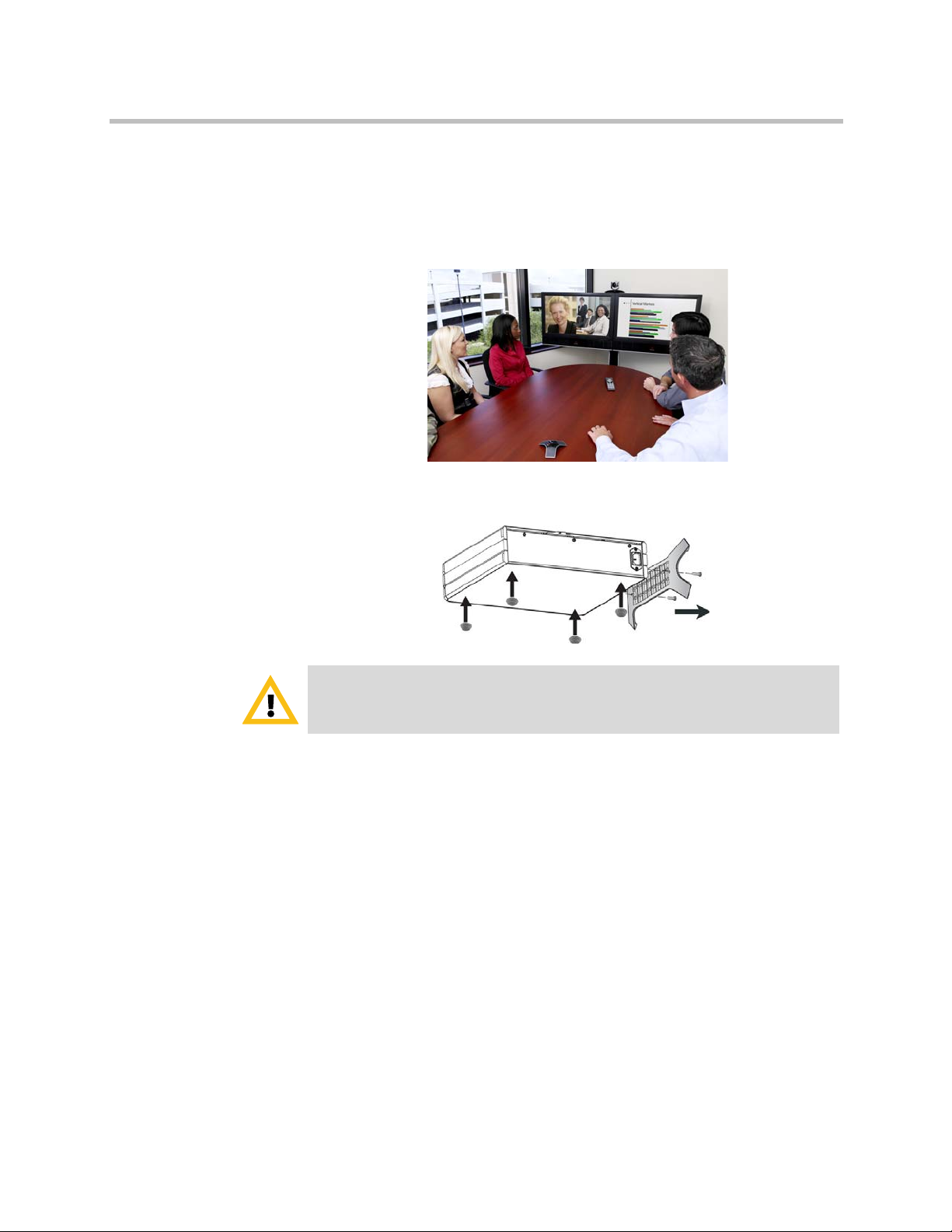
Positioning the System . . . . . . . . . . . . . . . . . . . . . . . . . . . . . . . . . . . . . . . . . . . . . . . . . . 1–4
Positioning the Polycom HDX 9000 Series Systems . . . . . . . . . . . . . . . . . . . . . 1–4
Positioning the Polycom HDX 8000 Series, Polycom HDX 7000 Series, or
Polycom HDX 6000 Series Systems . . . . . . . . . . . . . . . . . . . . . . . . . . . . . . . . . . . 1–4
Positioning the Polycom HDX 4000 Series Systems . . . . . . . . . . . . . . . . . . . . . 1–5
Positioning the Polycom Touch Control Device . . . . . . . . . . . . . . . . . . . . . . . . 1–6
Positioning the Polycom EagleEye Director . . . . . . . . . . . . . . . . . . . . . . . . . . . . 1–7
Powering On and Off . . . . . . . . . . . . . . . . . . . . . . . . . . . . . . . . . . . . . . . . . . . . . . . . . . . 1–8
Power-On Self Test (POST) . . . . . . . . . . . . . . . . . . . . . . . . . . . . . . . . . . . . . . . . . . 1–9
Powering On the Polycom HDX 9000 Series Systems . . . . . . . . . . . . . . . . . . . . 1–9
Polycom HDX 9000 Series Indicator Light . . . . . . . . . . . . . . . . . . . . . . . . . . . . 1–10
Powering On the Polycom HDX 8000 Series, Polycom HDX 7000 Series, or
Polycom HDX 6000 Series Systems . . . . . . . . . . . . . . . . . . . . . . . . . . . . . . . . . . 1–10
Polycom HDX 8000 Series, Polycom HDX 7000 Series, and
Polycom HDX 6000 Series Indicator Light . . . . . . . . . . . . . . . . . . . . . . . . . . . . 1–11
Powering On the Polycom HDX 4000 Systems . . . . . . . . . . . . . . . . . . . . . . . . 1–11
Polycom HDX 4000 Systems Indicator Lights . . . . . . . . . . . . . . . . . . . . . . . . . 1–12
Powering the Polycom HDX 4500 System On and Off . . . . . . . . . . . . . . . . . . 1–13
Polycom HDX 4500 System Indicator Lights . . . . . . . . . . . . . . . . . . . . . . . . . . 1–14
Powering On the Polycom Touch Control Device . . . . . . . . . . . . . . . . . . . . . . 1–15
Polycom Touch Control Indicator Light . . . . . . . . . . . . . . . . . . . . . . . . . . . . . . 1–16
Polycom EagleEye Director Indicator Light . . . . . . . . . . . . . . . . . . . . . . . . . . . 1–16
Configuring the Polycom HDX System . . . . . . . . . . . . . . . . . . . . . . . . . . . . . . . . . . . 1–16
Setup Wizard . . . . . . . . . . . . . . . . . . . . . . . . . . . . . . . . . . . . . . . . . . . . . . . . . . . . . 1–16
Admin Settings . . . . . . . . . . . . . . . . . . . . . . . . . . . . . . . . . . . . . . . . . . . . . . . . . . . 1–17
2Networks
Getting the Network Ready . . . . . . . . . . . . . . . . . . . . . . . . . . . . . . . . . . . . . . . . . . . . . 2–1
Connecting to the LAN . . . . . . . . . . . . . . . . . . . . . . . . . . . . . . . . . . . . . . . . . . . . . . . . . 2–1
Polycom, Inc. v
Artisan Technology Group - Quality Instrumentation ... Guaranteed | (888) 88-SOURCE | www.artisantg.com
Page 7

Administrator’s Guide for Polycom HDX Systems
LAN Status Lights . . . . . . . . . . . . . . . . . . . . . . . . . . . . . . . . . . . . . . . . . . . . . . . . . . 2–2
Configuring LAN Properties . . . . . . . . . . . . . . . . . . . . . . . . . . . . . . . . . . . . . . . . . 2–2
Configuring IP Settings . . . . . . . . . . . . . . . . . . . . . . . . . . . . . . . . . . . . . . . . . . . . . 2–8
Specifying SIP Settings . . . . . . . . . . . . . . . . . . . . . . . . . . . . . . . . . . . . . . . . . . . . . 2–15
Specifying Quality of Service . . . . . . . . . . . . . . . . . . . . . . . . . . . . . . . . . . . . . . . 2–20
Configuring the System for Use with a Firewall or NAT . . . . . . . . . . . . . . . . 2–22
Connecting Polycom HDX Systems to ISDN or Other Networks . . . . . . . . . . . . . 2–26
Quad BRI Network Interface Status Lights . . . . . . . . . . . . . . . . . . . . . . . . . . . . 2–28
PRI Network Interface Status Lights . . . . . . . . . . . . . . . . . . . . . . . . . . . . . . . . . 2–28
Serial V.35/RS-449/RS-530 Network Interface Status Lights . . . . . . . . . . . . 2–29
Configuring ISDN and Other Network Interface Settings . . . . . . . . . . . . . . . . . . . 2–29
Configuring the BRI Network Interface . . . . . . . . . . . . . . . . . . . . . . . . . . . . . . 2–29
Configuring the PRI Network Interface . . . . . . . . . . . . . . . . . . . . . . . . . . . . . . 2–31
Configuring the Serial V.35/RS-449/RS-530 Network Interface . . . . . . . . . . 2–33
Connecting to an Analog Phone Line . . . . . . . . . . . . . . . . . . . . . . . . . . . . . . . . . . . . 2–35
Configuring Telephony . . . . . . . . . . . . . . . . . . . . . . . . . . . . . . . . . . . . . . . . . . . . . . . . 2–36
Configuring Call Preferences . . . . . . . . . . . . . . . . . . . . . . . . . . . . . . . . . . . . . . . . . . . 2–37
Configuring Dialing Order Settings . . . . . . . . . . . . . . . . . . . . . . . . . . . . . . . . . . . . . . 2–41
Configuring Polycom HDX System LAN Properties . . . . . . . . . . . . . . . . 2–3
Configuring the Polycom Touch Control LAN Properties . . . . . . . . . . . . 2–7
Specifying H.323 Settings . . . . . . . . . . . . . . . . . . . . . . . . . . . . . . . . . . . . . . . 2–8
Configuring the System to Use a Gatekeeper . . . . . . . . . . . . . . . . . . . . . . . 2–9
IPv6 Gatekeeper Support . . . . . . . . . . . . . . . . . . . . . . . . . . . . . . . . . . . . . . . 2–11
Configuring Integration with Avaya Networks . . . . . . . . . . . . . . . . . . . . 2–12
Configuring the System to Use a Gateway . . . . . . . . . . . . . . . . . . . . . . . . 2–14
Configuring SIP Settings for Integration with Microsoft Office
Communications Server 2007 R2 and Microsoft Lync Server 2010 . . . . 2–18
Configuring SIP Settings for Integration with the Telepresence
Interoperability Protocol (TIP) . . . . . . . . . . . . . . . . . . . . . . . . . . . . . . . . . . 2–19
RTV and Lync-Hosted Conference Support . . . . . . . . . . . . . . . . . . . . . . . 2–20
Polycom Video Error Concealment and Dynamic Bandwidth . . . . . . . 2–20
Quality of Service Settings . . . . . . . . . . . . . . . . . . . . . . . . . . . . . . . . . . . . . . 2–21
Firewall Settings . . . . . . . . . . . . . . . . . . . . . . . . . . . . . . . . . . . . . . . . . . . . . . 2–22
H.460 Firewall/NAT Traversal . . . . . . . . . . . . . . . . . . . . . . . . . . . . . . . . . . 2–24
Basic Firewall/NAT Traversal Connectivity . . . . . . . . . . . . . . . . . . . . . . 2–25
3 Monitors and Cameras
Connecting Monitors . . . . . . . . . . . . . . . . . . . . . . . . . . . . . . . . . . . . . . . . . . . . . . . . . . . 3–1
Connecting Monitors to Polycom HDX 9000 Series Systems . . . . . . . . . . . . . . 3–1
Connecting Monitors to Polycom HDX 8000 Series or
Polycom HDX 7000 Series Systems . . . . . . . . . . . . . . . . . . . . . . . . . . . . . . . . . . . 3–2
Connecting a Monitor to Polycom HDX 6000 Series Systems . . . . . . . . . . . . . 3–2
Connecting a Monitor to a Polycom HDX 4500 System . . . . . . . . . . . . . . . . . . 3–3
Using a Polycom HDX 4000 Series System Monitor with a Computer . . . . . 3–3
Configuring Monitor Settings . . . . . . . . . . . . . . . . . . . . . . . . . . . . . . . . . . . . . . . . . . . . 3–3
Using Dual Monitor Emulation . . . . . . . . . . . . . . . . . . . . . . . . . . . . . . . . . . . . . 3–10
Examples of Dual Monitor Emulation . . . . . . . . . . . . . . . . . . . . . . . . . . . . 3–11
Using Dual Monitor Emulation in a Call . . . . . . . . . . . . . . . . . . . . . . . . . 3–11
Configuring Multipoint Viewing Modes . . . . . . . . . . . . . . . . . . . . . . . . . . . . . 3–12
vi Polycom, Inc.
Artisan Technology Group - Quality Instrumentation ... Guaranteed | (888) 88-SOURCE | www.artisantg.com
Page 8

Contents
Adjusting the Monitor’s Color Balance, Sharpness, and Brightness . . . . . . . 3–13
Preventing Monitor Burn-In . . . . . . . . . . . . . . . . . . . . . . . . . . . . . . . . . . . . . . . . 3–14
Connecting Cameras . . . . . . . . . . . . . . . . . . . . . . . . . . . . . . . . . . . . . . . . . . . . . . . . . . 3–15
Polycom EagleEye HD . . . . . . . . . . . . . . . . . . . . . . . . . . . . . . . . . . . . . . . . . . . . . 3–15
Polycom EagleEye 1080 . . . . . . . . . . . . . . . . . . . . . . . . . . . . . . . . . . . . . . . . . . . . 3–16
Polycom EagleEye View . . . . . . . . . . . . . . . . . . . . . . . . . . . . . . . . . . . . . . . . . . . 3–16
Polycom EagleEye II . . . . . . . . . . . . . . . . . . . . . . . . . . . . . . . . . . . . . . . . . . . . . . . 3–16
Polycom EagleEye III . . . . . . . . . . . . . . . . . . . . . . . . . . . . . . . . . . . . . . . . . . . . . . 3–17
Polycom EagleEye Director . . . . . . . . . . . . . . . . . . . . . . . . . . . . . . . . . . . . . . . . . 3–17
Connecting Cameras to Polycom HDX Systems . . . . . . . . . . . . . . . . . . . . . . . 3–18
Polycom HDX 9000 Series Systems . . . . . . . . . . . . . . . . . . . . . . . . . . . . . . 3–18
Polycom HDX 8000 Series Systems . . . . . . . . . . . . . . . . . . . . . . . . . . . . . . 3–21
Polycom HDX 7000 Series Systems . . . . . . . . . . . . . . . . . . . . . . . . . . . . . . 3–22
Polycom HDX 6000 Series Systems . . . . . . . . . . . . . . . . . . . . . . . . . . . . . . 3–23
Polycom HDX 4000 Series Systems . . . . . . . . . . . . . . . . . . . . . . . . . . . . . . 3–24
Polycom HDX 4500 Systems . . . . . . . . . . . . . . . . . . . . . . . . . . . . . . . . . . . . 3–24
Configuring Camera Settings and Video Quality Options . . . . . . . . . . . . . . . . . . . 3–25
Configuring the Polycom EagleEye Director . . . . . . . . . . . . . . . . . . . . . . . . . . 3–31
Getting Started . . . . . . . . . . . . . . . . . . . . . . . . . . . . . . . . . . . . . . . . . . . . . . . 3–31
Calibrating the Cameras . . . . . . . . . . . . . . . . . . . . . . . . . . . . . . . . . . . . . . . 3–32
Adjusting the Room View . . . . . . . . . . . . . . . . . . . . . . . . . . . . . . . . . . . . . . 3–33
Starting and Stopping Camera Tracking with EagleEye Director . . . . . 3–33
Setting the Tracking Mode . . . . . . . . . . . . . . . . . . . . . . . . . . . . . . . . . . . . . 3–34
Configuring Advanced Camera Settings . . . . . . . . . . . . . . . . . . . . . . . . . . . . . . . . . 3–35
Configuring Camera Presets . . . . . . . . . . . . . . . . . . . . . . . . . . . . . . . . . . . . . . . . . . . . 3–36
Setting and Using Presets with the Remote Control or Keypad . . . . . . 3–37
Setting and Using Presets with the Polycom Touch Control . . . . . . . . . 3–37
Experiencing High-Definition Video Conferencing . . . . . . . . . . . . . . . . . . . . . . . . 3–38
Sending Video in High Definition . . . . . . . . . . . . . . . . . . . . . . . . . . . . . . . . . . . 3–39
Receiving and Displaying Video in High Definition . . . . . . . . . . . . . . . . . . . . 3–39
HD and SD Multipoint Calls . . . . . . . . . . . . . . . . . . . . . . . . . . . . . . . . . . . . . . . . 3–40
4 Microphones and Speakers
Connecting Audio Input . . . . . . . . . . . . . . . . . . . . . . . . . . . . . . . . . . . . . . . . . . . . . . . . 4–1
Connecting Audio Input to Polycom HDX 9000 Series Systems . . . . . . . . . . . 4–1
Connecting Audio Input to Polycom HDX 8000 Series Systems . . . . . . . . . . . 4–2
Connecting Audio Input to Polycom HDX 7000 Series Systems . . . . . . . . . . . 4–2
Connecting Audio Input to Polycom HDX 6000 Series Systems . . . . . . . . . . . 4–2
Connecting Audio Input to Polycom HDX 4000 Series Systems . . . . . . . . . . . 4–3
Connecting Devices to the Polycom HDX Microphone Input . . . . . . . . . . . . . 4–3
Connecting Polycom HDX Table or Ceiling Microphones . . . . . . . . . . . . 4–3
Using the Polycom EagleEye View Microphones . . . . . . . . . . . . . . . . . . . 4–3
Connecting a Polycom SoundStation IP 7000 Phone . . . . . . . . . . . . . . . . . 4–4
Connecting Devices to the Polycom HDX 9000 Series
Microphone Input . . . . . . . . . . . . . . . . . . . . . . . . . . . . . . . . . . . . . . . . . . . . . . 4–4
Connecting Devices to the Polycom HDX 8000 Series
Microphone Input . . . . . . . . . . . . . . . . . . . . . . . . . . . . . . . . . . . . . . . . . . . . . . 4–5
Connecting Devices to the Polycom HDX 7000 Series
Microphone Input . . . . . . . . . . . . . . . . . . . . . . . . . . . . . . . . . . . . . . . . . . . . . . 4–6
Polycom, Inc. vii
Artisan Technology Group - Quality Instrumentation ... Guaranteed | (888) 88-SOURCE | www.artisantg.com
Page 9

Administrator’s Guide for Polycom HDX Systems
Placing Polycom Microphones to Send Stereo from Your Site . . . . . . . . . . . . 4–8
Polycom Microphone Lights . . . . . . . . . . . . . . . . . . . . . . . . . . . . . . . . . . . . . . . . . 4–9
Connecting Non-Polycom Microphones or a Mixer to a
Polycom HDX System . . . . . . . . . . . . . . . . . . . . . . . . . . . . . . . . . . . . . . . . . . . . . . 4–9
Connecting Audio Output . . . . . . . . . . . . . . . . . . . . . . . . . . . . . . . . . . . . . . . . . . . . . . 4–10
Connecting Speakers to Polycom HDX 9000 Series Systems . . . . . . . . . . . . . 4–11
Connecting Speakers to Polycom HDX 8000 Series Systems or
Polycom HDX 7000 HD Systems with Hardware Versions A, B, or C . . . . . 4–11
Connecting Speakers to Polycom HDX 7000 HD Systems with
Hardware Version D . . . . . . . . . . . . . . . . . . . . . . . . . . . . . . . . . . . . . . . . . . . . . . 4–11
Connecting Speakers to Polycom HDX 6000 Series Systems . . . . . . . . . . . . . 4–12
Connecting Speakers to Polycom HDX 4500 Systems . . . . . . . . . . . . . . . . . . . 4–12
Connecting Speakers or Headphones to Polycom HDX 4000 Series
Systems . . . . . . . . . . . . . . . . . . . . . . . . . . . . . . . . . . . . . . . . . . . . . . . . . . . . . . . . . . 4–12
Placing Speakers to Play Stereo from Far Sites . . . . . . . . . . . . . . . . . . . . . . . . . 4–12
Setting the Speaker Volume . . . . . . . . . . . . . . . . . . . . . . . . . . . . . . . . . . . . . . . . 4–13
Configuring Audio Settings . . . . . . . . . . . . . . . . . . . . . . . . . . . . . . . . . . . . . . . . . . . . 4–14
General Audio Settings . . . . . . . . . . . . . . . . . . . . . . . . . . . . . . . . . . . . . . . . . . . . 4–14
StereoSurround Settings . . . . . . . . . . . . . . . . . . . . . . . . . . . . . . . . . . . . . . . . . . . 4–18
Audio Meters . . . . . . . . . . . . . . . . . . . . . . . . . . . . . . . . . . . . . . . . . . . . . . . . . . . . . 4–19
Testing StereoSurround . . . . . . . . . . . . . . . . . . . . . . . . . . . . . . . . . . . . . . . . . . . . 4–20
Polycom HDX System Settings for a Polycom Vortex Mixer . . . . . . . . . . . . . 4–21
Settings for Non-Polycom Microphones . . . . . . . . . . . . . . . . . . . . . . . . . . . . . . 4–21
Connecting Devices to the Polycom HDX 6000 Series
Microphone Input . . . . . . . . . . . . . . . . . . . . . . . . . . . . . . . . . . . . . . . . . . . . . . 4–7
Connecting Devices to the Polycom HDX 4000 Series
Microphone Input . . . . . . . . . . . . . . . . . . . . . . . . . . . . . . . . . . . . . . . . . . . . . . 4–7
5 Content and Closed Captions
Connecting VCR/DVDs . . . . . . . . . . . . . . . . . . . . . . . . . . . . . . . . . . . . . . . . . . . . . . . . 5–2
Configuring VCR/DVD Player Settings . . . . . . . . . . . . . . . . . . . . . . . . . . . . . . . . . . . 5–2
Playing a Videotape or DVD . . . . . . . . . . . . . . . . . . . . . . . . . . . . . . . . . . . . . . . . 5–2
Recording a Call to Videotape or DVD . . . . . . . . . . . . . . . . . . . . . . . . . . . . . . . . 5–3
Connecting Computers to Polycom HDX Systems . . . . . . . . . . . . . . . . . . . . . . . . . . 5–4
Configuring Content Sharing . . . . . . . . . . . . . . . . . . . . . . . . . . . . . . . . . . . . . . . . . . . . 5–4
Sending Analog and Digital Content . . . . . . . . . . . . . . . . . . . . . . . . . . . . . . . . . . 5–5
Configuring Content Display with People+Content IP . . . . . . . . . . . . . . . . . . . . . . 5–5
Configuring People on Content™ . . . . . . . . . . . . . . . . . . . . . . . . . . . . . . . . . . . . . . . . 5–6
Setting Up the Room for People on Content . . . . . . . . . . . . . . . . . . . . . . . . . . . . 5–7
Enabling and Calibrating People on Content on the System . . . . . . . . . . . . . . 5–7
Manually Setting White Balance . . . . . . . . . . . . . . . . . . . . . . . . . . . . . . . . . . . . . . 5–8
Configuring UC Board™ . . . . . . . . . . . . . . . . . . . . . . . . . . . . . . . . . . . . . . . . . . . . . . . . 5–8
Using the Polycom VisualBoard™ Application . . . . . . . . . . . . . . . . . . . . . . . . . . . . . 5–9
Supported Polycom HDX Systems . . . . . . . . . . . . . . . . . . . . . . . . . . . . . . . . . . . 5–10
Supported VisualBoard Devices . . . . . . . . . . . . . . . . . . . . . . . . . . . . . . . . . . . . . 5–10
Configuring Closed Captioning . . . . . . . . . . . . . . . . . . . . . . . . . . . . . . . . . . . . . . . . . 5–11
Via a Dial-Up Connection to the System’s RS-232 Serial Port . . . . . . . . . . . . 5–12
viii Polycom, Inc.
Artisan Technology Group - Quality Instrumentation ... Guaranteed | (888) 88-SOURCE | www.artisantg.com
Page 10

Via the System’s Serial RS-232 Port . . . . . . . . . . . . . . . . . . . . . . . . . . . . . . . . . . 5–13
Via the Polycom HDX Web Interface . . . . . . . . . . . . . . . . . . . . . . . . . . . . . . . . . 5–14
6 Calling and Answering
Configuring Call Settings . . . . . . . . . . . . . . . . . . . . . . . . . . . . . . . . . . . . . . . . . . . . . . . 6–1
Setting the Call Answering Mode . . . . . . . . . . . . . . . . . . . . . . . . . . . . . . . . . . . . . . . . 6–2
Configuring Multipoint Calling . . . . . . . . . . . . . . . . . . . . . . . . . . . . . . . . . . . . . . . . . . 6–3
Entering a Multipoint Option Key . . . . . . . . . . . . . . . . . . . . . . . . . . . . . . . . . . . . 6–3
Configuring the Conference on Demand Feature . . . . . . . . . . . . . . . . . . . . . . . 6–4
Including Multiple Sites in a Cascaded Call . . . . . . . . . . . . . . . . . . . . . . . . . . . . 6–4
Configuring Directory Settings . . . . . . . . . . . . . . . . . . . . . . . . . . . . . . . . . . . . . . . . . . . 6–6
Creating a Localized System Name with the Polycom HDX Web Interface . 6–7
Managing Directories with the Polycom HDX Web Interface . . . . . . . . . . . . . 6–8
Using Multitiered Directory Navigation . . . . . . . . . . . . . . . . . . . . . . . . . . . . . . . 6–9
Enabling MTD on a Provisioned HDX System . . . . . . . . . . . . . . . . . . . . . 6–9
Enabling MTD on a Non-Provisioned HDX System . . . . . . . . . . . . . . . . 6–10
Configuring the Global Directory . . . . . . . . . . . . . . . . . . . . . . . . . . . . . . . . . . . . . . . 6–11
Directory Groups . . . . . . . . . . . . . . . . . . . . . . . . . . . . . . . . . . . . . . . . . . . . . . . . . . . . . 6–16
Global Directory Groups . . . . . . . . . . . . . . . . . . . . . . . . . . . . . . . . . . . . . . . . . . . 6–17
Favorites Group . . . . . . . . . . . . . . . . . . . . . . . . . . . . . . . . . . . . . . . . . . . . . . . . . . 6–17
Polycom Conferencing for Microsoft Outlook . . . . . . . . . . . . . . . . . . . . . . . . . 6–18
Contents
7 System Location, Appearance, and Tones
Configuring Regional Settings . . . . . . . . . . . . . . . . . . . . . . . . . . . . . . . . . . . . . . . . . . . 7–1
Configuring Polycom HDX Regional Settings . . . . . . . . . . . . . . . . . . . . . . . . . . 7–1
Configuring Polycom Touch Control Regional Settings . . . . . . . . . . . . . . . . . . 7–2
Customizing the Home Screen . . . . . . . . . . . . . . . . . . . . . . . . . . . . . . . . . . . . . . . . . . . 7–3
Displaying Speed Dial Entries . . . . . . . . . . . . . . . . . . . . . . . . . . . . . . . . . . . . . . . 7–6
Adding Marquee Text . . . . . . . . . . . . . . . . . . . . . . . . . . . . . . . . . . . . . . . . . . . . . . 7–6
Customizing Camera Names and Icons . . . . . . . . . . . . . . . . . . . . . . . . . . . . . . . . . . . 7–7
Screen Savers . . . . . . . . . . . . . . . . . . . . . . . . . . . . . . . . . . . . . . . . . . . . . . . . . . . . . . . . . . 7–8
Adding Screen Saver Text . . . . . . . . . . . . . . . . . . . . . . . . . . . . . . . . . . . . . . . . . . . 7–8
Adding a Screen Saver Logo . . . . . . . . . . . . . . . . . . . . . . . . . . . . . . . . . . . . . . . . . 7–8
8Security
Screens that Require a Password for Access . . . . . . . . . . . . . . . . . . . . . . . . . . . . . . . . 8–2
Using Security Profiles . . . . . . . . . . . . . . . . . . . . . . . . . . . . . . . . . . . . . . . . . . . . . . . . . . 8–2
Configuring Security Mode . . . . . . . . . . . . . . . . . . . . . . . . . . . . . . . . . . . . . . . . . . 8–3
Managing System Access . . . . . . . . . . . . . . . . . . . . . . . . . . . . . . . . . . . . . . . . . . . . . . . . 8–5
External Authentication . . . . . . . . . . . . . . . . . . . . . . . . . . . . . . . . . . . . . . . . . . . . . 8–5
Login and Credentials . . . . . . . . . . . . . . . . . . . . . . . . . . . . . . . . . . . . . . . . . . . . . . 8–7
Local Access . . . . . . . . . . . . . . . . . . . . . . . . . . . . . . . . . . . . . . . . . . . . . . . . . . . 8–8
Remote Access . . . . . . . . . . . . . . . . . . . . . . . . . . . . . . . . . . . . . . . . . . . . . . . . . 8–9
Configuring Admin ID and Password for the Polycom Touch Control . . . . 8–11
Managing User Access to Settings and Features . . . . . . . . . . . . . . . . . . . . . . . 8–12
Polycom, Inc. ix
Artisan Technology Group - Quality Instrumentation ... Guaranteed | (888) 88-SOURCE | www.artisantg.com
Page 11

Administrator’s Guide for Polycom HDX Systems
Local Accounts . . . . . . . . . . . . . . . . . . . . . . . . . . . . . . . . . . . . . . . . . . . . . . . . . . . 8–14
Setting Account and Port Lockouts . . . . . . . . . . . . . . . . . . . . . . . . . . . . . . . . . . 8–15
Enabling a Whitelist . . . . . . . . . . . . . . . . . . . . . . . . . . . . . . . . . . . . . . . . . . . . . . . . . . . 8–19
Enabling AES Encryption . . . . . . . . . . . . . . . . . . . . . . . . . . . . . . . . . . . . . . . . . . . . . . 8–20
List of Sessions . . . . . . . . . . . . . . . . . . . . . . . . . . . . . . . . . . . . . . . . . . . . . . . . . . . . . . . 8–21
Managing Certificates and Revocation . . . . . . . . . . . . . . . . . . . . . . . . . . . . . . . . . . . 8–22
Security Banners . . . . . . . . . . . . . . . . . . . . . . . . . . . . . . . . . . . . . . . . . . . . . . . . . . . . . . 8–31
Setting up Log Management . . . . . . . . . . . . . . . . . . . . . . . . . . . . . . . . . . . . . . . . . . . . 8–33
Setting up Polycom HDX Log Management . . . . . . . . . . . . . . . . . . . . . . . . . . 8–33
Managing Polycom Touch Control Logs . . . . . . . . . . . . . . . . . . . . . . . . . . . . . . 8–35
Configuring a Meeting Password . . . . . . . . . . . . . . . . . . . . . . . . . . . . . . . . . . . . . . . . 8–35
Detecting Intrusions . . . . . . . . . . . . . . . . . . . . . . . . . . . . . . . . . . . . . . . . . . . 8–13
Password Policies . . . . . . . . . . . . . . . . . . . . . . . . . . . . . . . . . . . . . . . . . . . . . 8–14
Account Lockout . . . . . . . . . . . . . . . . . . . . . . . . . . . . . . . . . . . . . . . . . . . . . . 8–15
Port Lockout . . . . . . . . . . . . . . . . . . . . . . . . . . . . . . . . . . . . . . . . . . . . . . . . . 8–17
Configuring Encryption Settings for Integration with
Microsoft Servers . . . . . . . . . . . . . . . . . . . . . . . . . . . . . . . . . . . . . . . . . . . . . 8–21
Generating Certificate Signing Requests (CSRs) . . . . . . . . . . . . . . . . . . . 8–23
Installing Certificates . . . . . . . . . . . . . . . . . . . . . . . . . . . . . . . . . . . . . . . . . . 8–25
Configuring Certificate Validation Settings . . . . . . . . . . . . . . . . . . . . . . . 8–26
Configuring Certificate Revocation Settings . . . . . . . . . . . . . . . . . . . . . . 8–26
Certificates and Security Profiles within a Provisioned System . . . . . . 8–29
Deleting Certificates and CRLs . . . . . . . . . . . . . . . . . . . . . . . . . . . . . . . . . . 8–31
RealPresence Server Address Configuration in PKI-enabled
Environments . . . . . . . . . . . . . . . . . . . . . . . . . . . . . . . . . . . . . . . . . . . . . . . . 8–31
9 Managing the System Remotely
Using the Polycom HDX Web Interface . . . . . . . . . . . . . . . . . . . . . . . . . . . . . . . . . . . 9–1
Accessing the Polycom HDX Web Interface . . . . . . . . . . . . . . . . . . . . . . . . . . . . 9–1
Monitoring a Room or Call with the Polycom HDX Web Interface . . . . . . . . 9–2
Managing System Profiles with the Polycom HDX Web Interface . . . . . . . . . 9–3
Sending a Message . . . . . . . . . . . . . . . . . . . . . . . . . . . . . . . . . . . . . . . . . . . . . . . . . 9–4
Configuring Global Services . . . . . . . . . . . . . . . . . . . . . . . . . . . . . . . . . . . . . . . . . . . . . 9–4
Viewing the Management Servers List . . . . . . . . . . . . . . . . . . . . . . . . . . . . . . . . 9–4
Requiring an Account Number for Calls . . . . . . . . . . . . . . . . . . . . . . . . . . . . . . . 9–5
Adding Information for the Global Management System
Administrator . . . . . . . . . . . . . . . . . . . . . . . . . . . . . . . . . . . . . . . . . . . . . . . . . . . . . 9–5
Requesting Technical Support from the Global Management
System Administrator . . . . . . . . . . . . . . . . . . . . . . . . . . . . . . . . . . . . . . . . . . . . . . 9–6
Setting Up SNMP . . . . . . . . . . . . . . . . . . . . . . . . . . . . . . . . . . . . . . . . . . . . . . . . . . 9–6
Downloading MIBs . . . . . . . . . . . . . . . . . . . . . . . . . . . . . . . . . . . . . . . . . . . . . 9–7
Configuring for SNMP Management . . . . . . . . . . . . . . . . . . . . . . . . . . . . . . 9–7
Using a Provisioning Service . . . . . . . . . . . . . . . . . . . . . . . . . . . . . . . . . . . . . . . . 9–8
Enabling or Disabling the Provisioning Service . . . . . . . . . . . . . . . . . . . . . 9–9
Provisioning Service Settings . . . . . . . . . . . . . . . . . . . . . . . . . . . . . . . . . . . 9–10
Keeping your Software Current . . . . . . . . . . . . . . . . . . . . . . . . . . . . . . . . . . . . . . . . . 9–11
x Polycom, Inc.
Artisan Technology Group - Quality Instrumentation ... Guaranteed | (888) 88-SOURCE | www.artisantg.com
Page 12

10 Control Devices
Configuring Remote Control Behavior . . . . . . . . . . . . . . . . . . . . . . . . . . . . . . . . . . . 10–1
Configuring the Remote Control Channel ID . . . . . . . . . . . . . . . . . . . . . . . . . . 10–3
Configuring the Remote to Control a Recording Device . . . . . . . . . . . . . . . . 10–3
Connecting Control and Accessibility Equipment . . . . . . . . . . . . . . . . . . . . . . . . . . 10–4
Connecting Non-Polycom Touch-Panel Controls . . . . . . . . . . . . . . . . . . . . . . 10–4
Connecting IR Sensors to Polycom HDX Systems . . . . . . . . . . . . . . . . . . . . . . 10–4
Configuring RS-232 Serial Port Settings . . . . . . . . . . . . . . . . . . . . . . . . . . . . . . . . . . 10–5
Setting Up the Polycom Touch Control Device . . . . . . . . . . . . . . . . . . . . . . . . . . . . 10–6
Pairing and Unpairing a Polycom Touch Control Device
and a Polycom HDX System . . . . . . . . . . . . . . . . . . . . . . . . . . . . . . . . . . . . . . . . 10–8
Managing the Polycom Touch Control Remotely . . . . . . . . . . . . . . . . . . . . . 10–10
Using SmartPairing™ . . . . . . . . . . . . . . . . . . . . . . . . . . . . . . . . . . . . . . . . . . . . . . . . . 10–11
Enabling SmartPairing Within Security Setting Guidelines . . . . . . . . . . . . . 10–11
Using Telnet to Enable SmartPairing . . . . . . . . . . . . . . . . . . . . . . . . . . . . . . . . 10–12
Additional Notes on SmartPairing . . . . . . . . . . . . . . . . . . . . . . . . . . . . . . . . . . 10–13
Contents
Pairing . . . . . . . . . . . . . . . . . . . . . . . . . . . . . . . . . . . . . . . . . . . . . . . . . . . . . . 10–9
Unpairing . . . . . . . . . . . . . . . . . . . . . . . . . . . . . . . . . . . . . . . . . . . . . . . . . . . 10–10
Download Logs . . . . . . . . . . . . . . . . . . . . . . . . . . . . . . . . . . . . . . . . . . . . . . 10–10
Network Settings . . . . . . . . . . . . . . . . . . . . . . . . . . . . . . . . . . . . . . . . . . . . 10–10
Pairing . . . . . . . . . . . . . . . . . . . . . . . . . . . . . . . . . . . . . . . . . . . . . . . . . . . . . 10–10
Security . . . . . . . . . . . . . . . . . . . . . . . . . . . . . . . . . . . . . . . . . . . . . . . . . . . . . 10–11
Software Updates . . . . . . . . . . . . . . . . . . . . . . . . . . . . . . . . . . . . . . . . . . . . 10–11
View Touch Control Screens . . . . . . . . . . . . . . . . . . . . . . . . . . . . . . . . . . . 10–11
Screen Savers and Sleep Mode . . . . . . . . . . . . . . . . . . . . . . . . . . . . . . . . . 10–13
Maximum Number of Connections . . . . . . . . . . . . . . . . . . . . . . . . . . . . . 10–13
More than One SmartPairing Signal . . . . . . . . . . . . . . . . . . . . . . . . . . . . 10–14
Automatic Versus Manual Pairing . . . . . . . . . . . . . . . . . . . . . . . . . . . . . . 10–14
11 Statistics and Diagnostics
Diagnostics Screens . . . . . . . . . . . . . . . . . . . . . . . . . . . . . . . . . . . . . . . . . . . . . . . . . . . 11–1
System Status . . . . . . . . . . . . . . . . . . . . . . . . . . . . . . . . . . . . . . . . . . . . . . . . . . . . . 11–2
Server Status . . . . . . . . . . . . . . . . . . . . . . . . . . . . . . . . . . . . . . . . . . . . . . . . . . . . . 11–3
Call Summary . . . . . . . . . . . . . . . . . . . . . . . . . . . . . . . . . . . . . . . . . . . . . . . . . . . . 11–3
Call Statistics . . . . . . . . . . . . . . . . . . . . . . . . . . . . . . . . . . . . . . . . . . . . . . . . . . . . . 11–3
Network . . . . . . . . . . . . . . . . . . . . . . . . . . . . . . . . . . . . . . . . . . . . . . . . . . . . . . . . . 11–5
Video (Monitors) . . . . . . . . . . . . . . . . . . . . . . . . . . . . . . . . . . . . . . . . . . . . . . . . . . 11–6
Video Cameras . . . . . . . . . . . . . . . . . . . . . . . . . . . . . . . . . . . . . . . . . . . . . . . . . . . 11–6
Audio . . . . . . . . . . . . . . . . . . . . . . . . . . . . . . . . . . . . . . . . . . . . . . . . . . . . . . . . . . . 11–7
Reset or Restart System . . . . . . . . . . . . . . . . . . . . . . . . . . . . . . . . . . . . . . . . . . . . 11–8
Send a Message . . . . . . . . . . . . . . . . . . . . . . . . . . . . . . . . . . . . . . . . . . . . . . . . . . . 11–8
System Log . . . . . . . . . . . . . . . . . . . . . . . . . . . . . . . . . . . . . . . . . . . . . . . . . . . . . . . 11–8
Sessions . . . . . . . . . . . . . . . . . . . . . . . . . . . . . . . . . . . . . . . . . . . . . . . . . . . . . . . . . . 11–8
Recent Calls . . . . . . . . . . . . . . . . . . . . . . . . . . . . . . . . . . . . . . . . . . . . . . . . . . . . . . . . . . 11–9
Call Detail Report (CDR) . . . . . . . . . . . . . . . . . . . . . . . . . . . . . . . . . . . . . . . . . . . . . . . 11–9
Information in the CDR . . . . . . . . . . . . . . . . . . . . . . . . . . . . . . . . . . . . . . . . . . . 11–10
Call Detail Report Archives . . . . . . . . . . . . . . . . . . . . . . . . . . . . . . . . . . . . . . . . 11–13
Polycom, Inc. xi
Artisan Technology Group - Quality Instrumentation ... Guaranteed | (888) 88-SOURCE | www.artisantg.com
Page 13

Administrator’s Guide for Polycom HDX Systems
System Logs . . . . . . . . . . . . . . . . . . . . . . . . . . . . . . . . . . . . . . . . . . . . . . . . . . . . . . . . . 11–13
Downloading System Logs from the Polycom HDX Web Interface . . . . . . 11–13
System Log Settings in the Polycom HDX Web Interface . . . . . . . . . . . . . . 11–14
Downloading EagleEye Director Logs . . . . . . . . . . . . . . . . . . . . . . . . . . . . . . 11–15
12 Troubleshooting
Placing a Test Call . . . . . . . . . . . . . . . . . . . . . . . . . . . . . . . . . . . . . . . . . . . . . . . . . . . . . 12–1
Enabling Diagnostic Mode . . . . . . . . . . . . . . . . . . . . . . . . . . . . . . . . . . . . . . . . . . . . . 12–2
Using the Restore Button on the Polycom HDX System . . . . . . . . . . . . . . . . . . . . . 12–2
Restoring Configuration . . . . . . . . . . . . . . . . . . . . . . . . . . . . . . . . . . . . . . . . . . . 12–4
Performing a Factory Restore . . . . . . . . . . . . . . . . . . . . . . . . . . . . . . . . . . . . . . . 12–4
Deleting Files . . . . . . . . . . . . . . . . . . . . . . . . . . . . . . . . . . . . . . . . . . . . . . . . . . . . . 12–5
Performing a Factory Restore on the Polycom Touch Control . . . . . . . . . . . . . . . 12–6
Performing a Factory Restore on the Polycom EagleEye Director . . . . . . . . . . . . 12–6
Changing the Video Format . . . . . . . . . . . . . . . . . . . . . . . . . . . . . . . . . . . . . . . . . . . . 12–7
How to Contact Technical Support . . . . . . . . . . . . . . . . . . . . . . . . . . . . . . . . . . . . . . 12–8
Polycom Solution Support . . . . . . . . . . . . . . . . . . . . . . . . . . . . . . . . . . . . . . . . . . . . . . 12–8
A System Back Panel Views
Video Inputs and Outputs . . . . . . . . . . . . . . . . . . . . . . . . . . . . . . . . . . . . . . . . . . . . . . A–1
Polycom HDX 9006 . . . . . . . . . . . . . . . . . . . . . . . . . . . . . . . . . . . . . . . . . . . . . . . . A–1
Polycom HDX 9004 . . . . . . . . . . . . . . . . . . . . . . . . . . . . . . . . . . . . . . . . . . . . . . . . A–2
Polycom HDX 9001 and Polycom HDX 9002 . . . . . . . . . . . . . . . . . . . . . . . . . . A–2
Polycom HDX 8000 Series System . . . . . . . . . . . . . . . . . . . . . . . . . . . . . . . . . . . A–3
Polycom HDX 7000 Series System (Hardware Versions A, B, C) . . . . . . . . . A–3
Polycom HDX 7000 System with Hardware Version D . . . . . . . . . . . . . . . . . A–4
Polycom HDX 6000 Series System . . . . . . . . . . . . . . . . . . . . . . . . . . . . . . . . . . . A–4
Polycom HDX 4000 and Polycom HDX 4000 HD Systems . . . . . . . . . . . . . . . A–5
Polycom HDX 4500 System . . . . . . . . . . . . . . . . . . . . . . . . . . . . . . . . . . . . . . . . . A–5
Audio Inputs and Outputs . . . . . . . . . . . . . . . . . . . . . . . . . . . . . . . . . . . . . . . . . . . . . A–6
Polycom HDX 9006 . . . . . . . . . . . . . . . . . . . . . . . . . . . . . . . . . . . . . . . . . . . . . . . . A–6
Polycom HDX 9004 . . . . . . . . . . . . . . . . . . . . . . . . . . . . . . . . . . . . . . . . . . . . . . . . A–6
Polycom HDX 9001 and Polycom HDX 9002 . . . . . . . . . . . . . . . . . . . . . . . . . . A–7
Polycom HDX 8000 Series System . . . . . . . . . . . . . . . . . . . . . . . . . . . . . . . . . . . A–7
Polycom HDX 7000 Series System (Hardware Versions A, B, C) . . . . . . . . . A–8
Polycom HDX 7000 System with Hardware Version D . . . . . . . . . . . . . . . . . A–8
Polycom HDX 6000 Series System . . . . . . . . . . . . . . . . . . . . . . . . . . . . . . . . . . . A–9
Polycom HDX 4000 and Polycom HDX 4000 HD Systems . . . . . . . . . . . . . . . A–9
Polycom HDX 4500 System . . . . . . . . . . . . . . . . . . . . . . . . . . . . . . . . . . . . . . . . A–10
Network/Power/Control Inputs and Outputs . . . . . . . . . . . . . . . . . . . . . . . . . . . A–10
Polycom HDX 9006 . . . . . . . . . . . . . . . . . . . . . . . . . . . . . . . . . . . . . . . . . . . . . . . A–10
Polycom HDX 9004 . . . . . . . . . . . . . . . . . . . . . . . . . . . . . . . . . . . . . . . . . . . . . . . A–11
Polycom HDX 9001 and Polycom HDX 9002 . . . . . . . . . . . . . . . . . . . . . . . . . A–11
Polycom HDX 8000 Series System . . . . . . . . . . . . . . . . . . . . . . . . . . . . . . . . . . A–12
Polycom HDX 7000 Series System (Hardware Versions A, B, C) . . . . . . . . A–12
xii Polycom, Inc.
Artisan Technology Group - Quality Instrumentation ... Guaranteed | (888) 88-SOURCE | www.artisantg.com
Page 14

Polycom HDX 7000 System with Hardware Version D . . . . . . . . . . . . . . . . A–13
Polycom HDX 6000 Series System . . . . . . . . . . . . . . . . . . . . . . . . . . . . . . . . . . A–13
Polycom HDX 4000 and Polycom HDX 4000 HD Systems . . . . . . . . . . . . . . A–14
Polycom HDX 4500 System . . . . . . . . . . . . . . . . . . . . . . . . . . . . . . . . . . . . . . . . A–14
BPort Usage
C Call Speeds and Resolutions
Point-to-Point Dialing Speeds . . . . . . . . . . . . . . . . . . . . . . . . . . . . . . . . . . . . . . . . . . . C–1
Multipoint Dialing Speeds . . . . . . . . . . . . . . . . . . . . . . . . . . . . . . . . . . . . . . . . . . . . . . C–1
Call Speeds and Resolutions . . . . . . . . . . . . . . . . . . . . . . . . . . . . . . . . . . . . . . . . . . . . C–4
SD Systems (NTSC) . . . . . . . . . . . . . . . . . . . . . . . . . . . . . . . . . . . . . . . . . . . . . . . C–4
HD 720p Systems (NTSC) . . . . . . . . . . . . . . . . . . . . . . . . . . . . . . . . . . . . . . . . . . C–5
HD 1080p Systems (NTSC) . . . . . . . . . . . . . . . . . . . . . . . . . . . . . . . . . . . . . . . . . C–6
H.264 High Profile . . . . . . . . . . . . . . . . . . . . . . . . . . . . . . . . . . . . . . . . . . . . . . . . C–7
High Profile on Polycom HDX 6000 HD . . . . . . . . . . . . . . . . . . . . . . . . . . C–7
High Profile on Polycom HDX 4000 HD, Polycom HDX 4500,
Polycom HDX 7000 HD, Polycom HDX 8000 HD, and
Polycom HDX 9006 . . . . . . . . . . . . . . . . . . . . . . . . . . . . . . . . . . . . . . . . . . . . C–8
Maximum Resolution (720p) on Polycom HDX 7000 Systems . . . . . . . . . . . C–9
Maximum Resolution (1080p) on Polycom HDX 6000 Systems . . . . . . . . . C–10
Resolution and Frame Rates for Content Video . . . . . . . . . . . . . . . . . . . . . . . . . . . C–10
Polycom HDX 9006, Polycom HDX 8000 HD with Hardware Version B,
Polycom HDX 7000 with Hardware Version C or D, Polycom HDX 4500,
Polycom HDX 4000 with Hardware Version C Systems . . . . . . . . . . . . . . . C–11
Polycom HDX 9004, Polycom HDX 9002, and
Polycom HDX 9001 Systems . . . . . . . . . . . . . . . . . . . . . . . . . . . . . . . . . . . . . . . C–11
Polycom HDX 6000 System . . . . . . . . . . . . . . . . . . . . . . . . . . . . . . . . . . . . . . . . C–12
Contents
D Codes for Remote Control Recording Device Buttons
DVD Player Codes . . . . . . . . . . . . . . . . . . . . . . . . . . . . . . . . . . . . . . . . . . . . . . . . . . . . D–1
DVD Recorder Codes . . . . . . . . . . . . . . . . . . . . . . . . . . . . . . . . . . . . . . . . . . . . . . . . . . D–2
VCR Device Codes . . . . . . . . . . . . . . . . . . . . . . . . . . . . . . . . . . . . . . . . . . . . . . . . . . . . D–3
PVR Device Codes . . . . . . . . . . . . . . . . . . . . . . . . . . . . . . . . . . . . . . . . . . . . . . . . . . . . D–5
E Security Profile Tables
Using the Maximum or High Security Profile . . . . . . . . . . . . . . . . . . . . . . . . . . . . . E–1
Using the Medium Security Profile . . . . . . . . . . . . . . . . . . . . . . . . . . . . . . . . . . . . . . E–7
Using the Low Security Profile . . . . . . . . . . . . . . . . . . . . . . . . . . . . . . . . . . . . . . . . . E–12
Using the Minimum Security Profile . . . . . . . . . . . . . . . . . . . . . . . . . . . . . . . . . . . . E–17
Index . . . . . . . . . . . . . . . . . . . . . . . . . . . . . . . . . . . . Index–1
Polycom, Inc. xiii
Artisan Technology Group - Quality Instrumentation ... Guaranteed | (888) 88-SOURCE | www.artisantg.com
Page 15

Administrator’s Guide for Polycom HDX Systems
xiv Polycom, Inc.
Artisan Technology Group - Quality Instrumentation ... Guaranteed | (888) 88-SOURCE | www.artisantg.com
Page 16

Introducing the Polycom HDX
Systems
Your Polycom HDX video conferencing system is a state-of-the-art visual
collaboration tool. With crisp, clean video and crystal-clear sound, Polycom
HDX systems provide natural video conferencing interaction through the
most advanced video communications technology.
1
Polycom HDX Systems
For technical specifications and detailed descriptions of features available for
Polycom HDX models, please refer to the product literature available at
support.polycom.com.
Polycom HDX 9000 Series Systems
The Polycom HDX 9000 series provides high-definition (HD) voice, video, and
content for medium to large conference rooms. The Polycom HDX 9000 series
provides integrator-class connectors and supports multiple video and audio
sources. These solutions allow integrators to create specialized and unique,
real-time video environments for their customers. The Polycom HDX 9000
series includes several models: Polycom HDX 9006, Polycom HDX 9004,
Polycom HDX 9002, and Polycom HDX 9001.
The Polycom HDX 9006 systems can send and receive wide-screen,
high-definition (HD) video in point-to-point and multipoint calls in 1080p
video.
The Polycom HDX 9004 and Polycom HDX 9002 systems can send and receive
wide-screen, high-definition (HD) video in point-to-point and multipoint
calls. The Polycom HDX 9001 sends and receives up to standard-definition
(SD) video.
Polycom, Inc. 1–1
Artisan Technology Group - Quality Instrumentation ... Guaranteed | (888) 88-SOURCE | www.artisantg.com
Page 17
Administrator’s Guide for Polycom HDX Systems
Polycom HDX 8000 Series Systems
The Polycom HDX 8000 series provides high-definition (HD) voice, video, and
content for medium to large conference rooms. These systems incorporate
leading-edge design with performance, flexibility, and capabilities, making
them the optimal solution for meeting spaces in any organization. The
Polycom HDX 8000 series systems can send and receive wide-screen,
HD 720p video in point-to-point and multipoint calls. Polycom HDX 8000
series systems with the 1080p Resolution option installed can send and receive
full HD (1080p) video.
The Polycom HDX 8000 series systems ship with a Polycom EagleEye™
camera, Polycom HDX microphones, and a Polycom HDX remote control.
Bundles including displays and furniture are also available.
Polycom HDX 7000 Series Systems
The Polycom HDX 7000 series provides voice, video, and content for small to
medium conference rooms. These systems incorporate leading-edge design
with performance, flexibility, and capabilities, making them the optimal
solution for meeting spaces in any organization.
The Polycom HDX 7000 series has two models: the Polycom HDX 7000 system
and the Polycom HDX 7000 HD system. The Polycom HDX 7000 system is an
SD system that sends and receives video in SD resolutions. The Polycom HDX
7000 HD system is an HD system that sends and receives HD video. Both
models include a Polycom EagleEye HD camera, Polycom HDX microphone,
and a Polycom HDX remote control. Polycom HDX 7000 series systems with
the 1080p Resolution option installed can send and receive full HD (1080p)
video. Polycom HDX 7000 HD systems with Hardware Version D, which
started shipping as of Polycom HDX software version 3.1.2, do not include the
audio and video output ports labeled on the back panel as VCR.
Bundles including displays and furniture are also available.
Polycom HDX 6000 Series Systems
The Polycom HDX 6000 series provides voice, video, and content for small to
medium conference rooms. These systems incorporate leading-edge design
with performance, flexibility, and capabilities, making them the optimal
solution for meeting spaces in any organization.
The Polycom HDX 6000 HD system is an HD system that sends and receives
HD video. Polycom HDX 6000 series systems with the 1080p Resolution
option installed can send and receive full HD (1080p) video.
The Polycom HDX 6000 series systems ship with a Polycom EagleEye camera,
a Polycom HDX microphone, and a Polycom HDX remote control. Bundles
including displays and furniture are also available.
1–2 Polycom, Inc.
Artisan Technology Group - Quality Instrumentation ... Guaranteed | (888) 88-SOURCE | www.artisantg.com
Page 18
Polycom HDX 4000 Series Systems
The Polycom HDX 4000 series provides the ultimate in desktop video
conferencing, designed to allow today’s professionals to be more productive
and effective right from their office. With LCD screens, powerful stereo
speakers, and sleek design, these systems are much more than
communications devices; they are also fully functional monitors for your PC
or Macintosh. The Polycom HDX 4000 series has three models: the Polycom
HDX 4000 system, the Polycom HDX 4000 HD system, and the Polycom HDX
4500 system.
The Polycom HDX 4000 system is an SD system that sends and receives video
in 4CIF/4SIF resolutions. The Polycom HDX 4000 HD system with Hardware
Version C is an HD system that sends and receives H.264 High Profile video.
The system can receive 720p and 1080p people video.
Built into the Polycom HDX 4000 and Polycom HDX 4000 HD systems are a
Pan Tilt Zoom (PTZ) camera, four speakers, and dual microphones.
The Polycom HDX 4500 system is the latest executive desktop video
conferencing system in the Polycom HDX 4000 series. The system has a 24”
screen, powerful stereo speakers, and sleek design and can send and receive
up to 1080p, HD video. You can attach a second monitor to the Polycom HDX
4500 system.
Introducing the Polycom HDX Systems
Built into the Polycom HDX 4500 system are a Pan Tilt Zoom (PTZ) camera,
two speakers, and dual microphones.
To find out which hardware version you have, go to System > System
Information.
The Polycom HDX 4500 system is the only Polycom HDX 4000 series system that
supports the Polycom Touch Control. When a Polycom Touch Control is paired with
the Polycom HDX 4500 system, the keypad and remote control are disabled.
Setting Up Your System Hardware
This manual provides information to supplement the setup sheets provided
with your system and its optional components. A printed copy of the system
setup sheet is provided with each Polycom HDX system. PDF versions of the
system setup sheets are available at support.polycom.com.
Polycom, Inc. 1–3
Artisan Technology Group - Quality Instrumentation ... Guaranteed | (888) 88-SOURCE | www.artisantg.com
Page 19
Administrator’s Guide for Polycom HDX Systems
1
2
Positioning the System
Positioning the Polycom HDX 9000 Series Systems
Polycom HDX 9000 series systems are designed to be placed on a tabletop or
in an equipment rack.
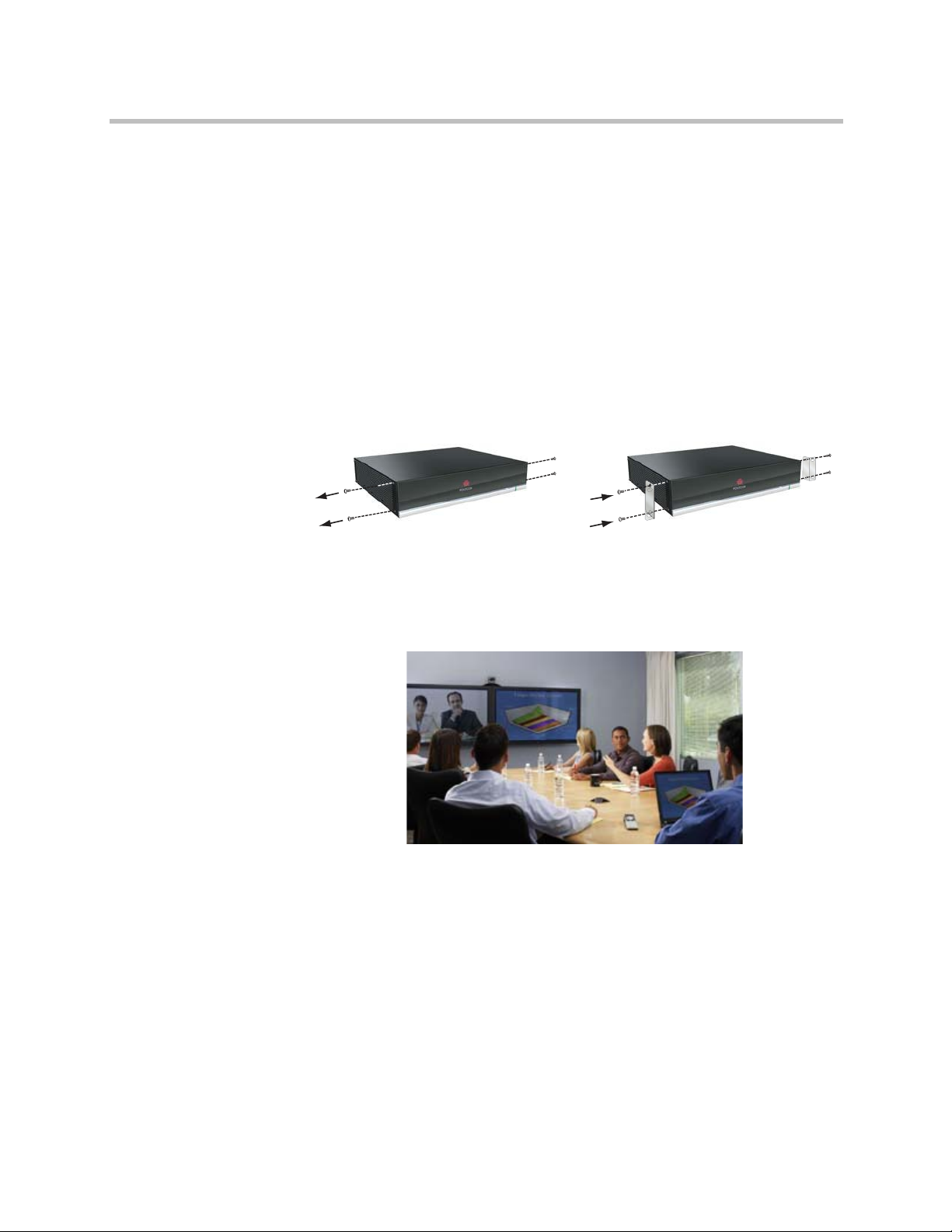
To position the system:
1 Install the mounting brackets on the system if you need to mount it in an
equipment rack, or install the self-adhesive feet if you will place the
system on a table or shelf.
2 Place the system in the desired location. Position the system so that the
camera does not face toward a window or other source of bright light.
Leave enough space to connect the cables easily. Place the camera and
display together so that people at your site face the camera when they are
looking at the display.
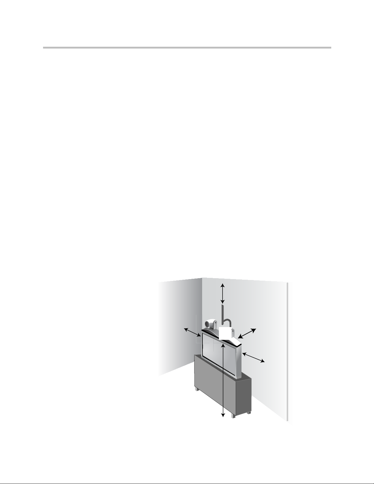
Positioning the Polycom HDX 8000 Series, Polycom HDX 7000 Series, or
Polycom HDX 6000 Series Systems
Polycom HDX 8000 series, Polycom HDX 7000 series, and Polycom HDX 6000
series systems can be set up in multiple ways. When used with furniture such
as a pedestal or wall mount, the system fits into a bracket on the back of the
display. The system can also be placed in a cart or on a table.
1–4 Polycom, Inc.
Artisan Technology Group - Quality Instrumentation ... Guaranteed | (888) 88-SOURCE | www.artisantg.com
Page 20
Introducing the Polycom HDX Systems
To position the system:
>> Position the system so that the camera does not face toward a window or
other source of bright light. Leave enough space to connect the cables
easily. Place the camera and display together so that people at your site
face the camera when they are looking at the display.
If you need to position the system horizontally, remove the stand and install
the self-adhesive feet.
Caution. Risk of Electric Shock. To reduce the risk of personal injury or damage to
the equipment, do not use screws longer than those supplied (M4x16, 8.00 mm
maximum head diameter) to reconnect the stand to the system.
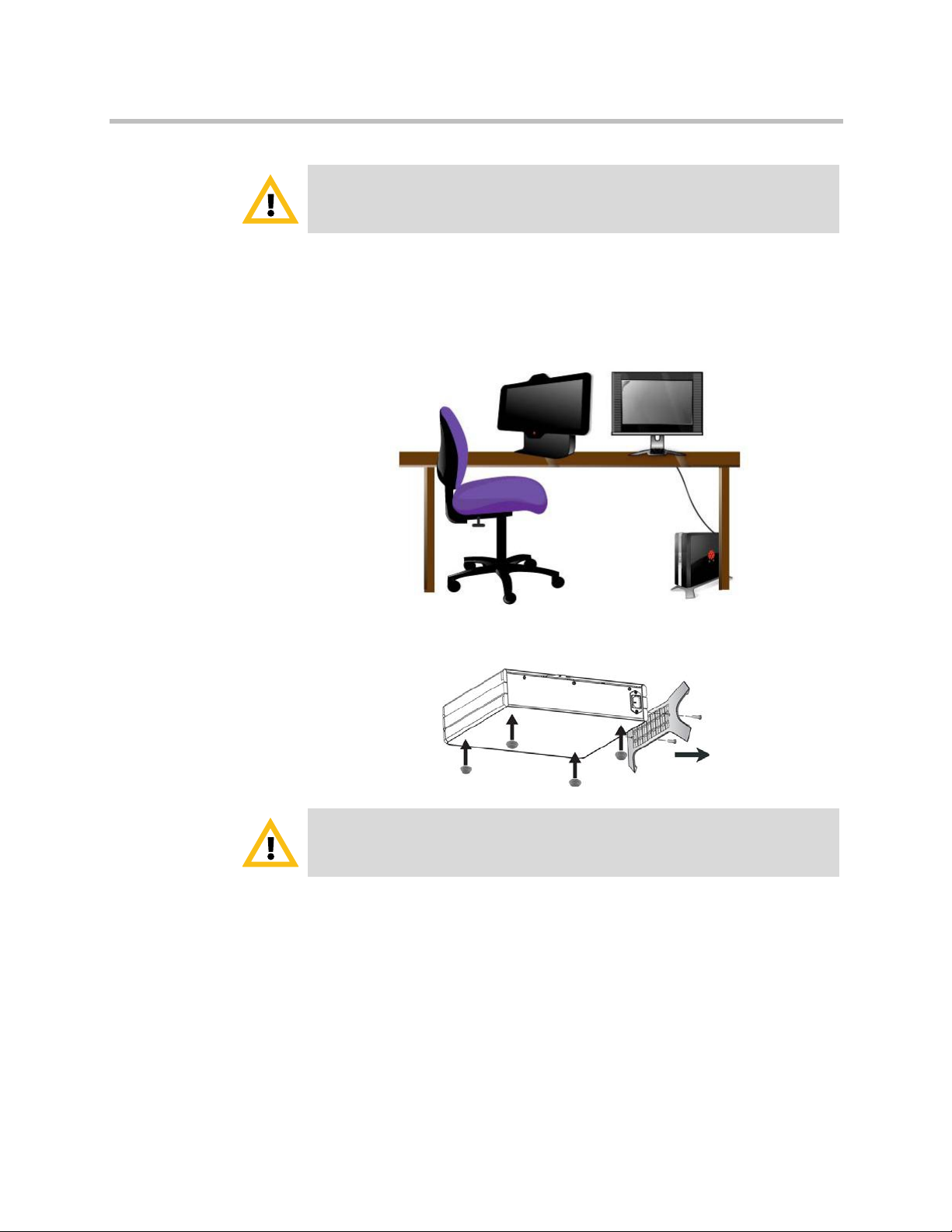
Positioning the Polycom HDX 4000 Series Systems
The Polycom HDX 4000 series systems are personal video conferencing
systems for the desktop.
The Polycom HDX 4500 system is an all-in-one device with the monitor and
system combined. Position the system so that the camera does not face toward
a window or other source of bright light.
To position the Polycom HDX 4000 or HDX 4000 HD system:
1 Place the monitor on the desktop, leaving enough space to connect the
cables easily. Position the system so that the camera does not face toward
a window or other source of bright light.
Polycom, Inc. 1–5
Artisan Technology Group - Quality Instrumentation ... Guaranteed | (888) 88-SOURCE | www.artisantg.com
Page 21
Administrator’s Guide for Polycom HDX Systems
Polycom HDX 4000,
Polycom HDX 4000 HD
systems
Polycom HDX 4500 system
Caution. Risk of Electric Shock. To reduce the risk of personal injury or damage to
the equipment, use the outlet on the back of the Polycom HDX 4500 only to plug
the display into the system.
2 Place the Polycom HDX 4000 or Polycom HDX 4000 HD system either
under the desk, or on the desk next to the display. The cables that connect
the display to the system can be hidden in the monitor stand, providing
clean cable management.
Positioning the Polycom Touch Control Device
If you need to position one of the Polycom HDX 4000 systems horizontally,
remove the stand and install the self-adhesive feet.
Caution. Risk of Electric Shock. To reduce the risk of personal injury or damage to
the equipment, do not use screws longer than those supplied (M4x16, 8.00 mm
maximum head diameter) to reconnect the stand to the system.
Polycom HDX 9000 series, Polycom HDX 8000 series, Polycom HDX 7000
series, Polycom HDX 6000 series, and the Polycom HDX 4500 systems can be
controlled by the Polycom Touch Control.
Ensure that the Touch Control is conveniently located for use during a
meeting.
1–6 Polycom, Inc.
Artisan Technology Group - Quality Instrumentation ... Guaranteed | (888) 88-SOURCE | www.artisantg.com
Page 22
≥12 in. (0.3 m)
≥12 in. (0.3 m)
≥12 in. (0.3 m)
5.5 - 7 ft. (1.7 - 2.1 m)
>12 in. (0.3 m)
When the Polycom Touch Control is not paired with a Polycom HDX system,
the device can be used as a virtual remote control. To use the Polycom Touch
Control as a virtual remote control, ensure that the infrared (IR) transmitter on
the front of the device is facing the Polycom HDX system you want to control.
When the Polycom Touch Control is paired with a Polycom HDX system, the
HDX system’s IR remote control is inoperable.
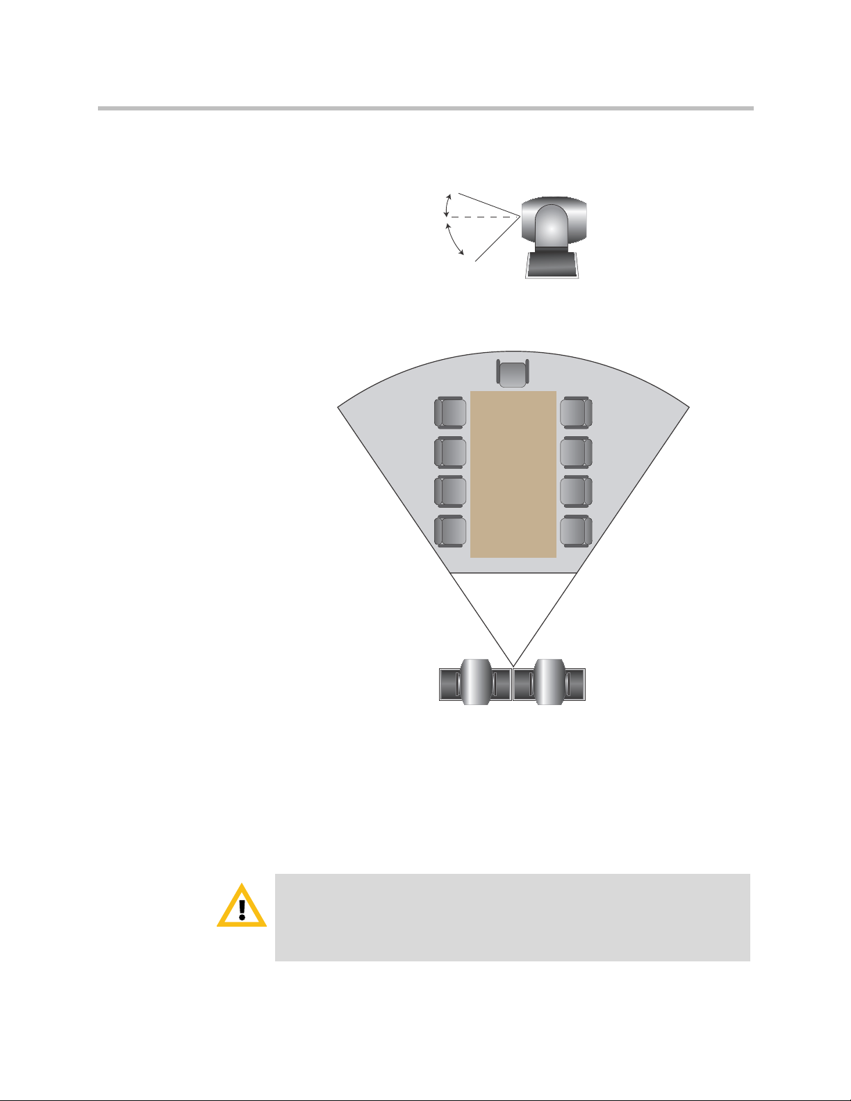
Positioning the Polycom EagleEye Director
The Polycom EagleEye Director is a new HD automatic camera positioning
system that works with Polycom HDX 9000 series, Polycom HDX 8000 series,
Polycom HDX 7000 series, and Polycom HDX 6000 series systems. Refer to
Polycom EagleEye Director on page 3-17 for more information about the
device.
Follow these guidelines when you use the Polycom EagleEye Director with
your HDX system:
• Avoid setting the Polycom EagleEye Director in the corner of a room. The
Polycom EagleEye Director should be at least 12 inches away from all of
the walls.
Introducing the Polycom HDX Systems
• Make sure the Polycom EagleEye Director is on a level surface or
mounting bracket.
• To ensure the best view from the Polycom EagleEye Director
voice-tracking feature, follow these suggestions:
— Set the Polycom EagleEye Director on top of a monitor. Ideally, place
the device between 5.5 and 7 feet from the ground.
Polycom, Inc. 1–7
Artisan Technology Group - Quality Instrumentation ... Guaranteed | (888) 88-SOURCE | www.artisantg.com
Page 23
Administrator’s Guide for Polycom HDX Systems
+9º
-30º
<22 ft. (6.7 m)
<22 ft. (6.7 m)
3 ft. (0.9 m)
3 ft. (0.9 m)
— Keep in mind that the camera view is 9 degrees above the line of sight
— Ensure that people are sitting within the viewing range of between 3
and up to 30 degrees below the line of sight.
and 22 feet from the device.
Powering On and Off
Connect power and power on the HDX system after you have connected all of
the equipment that you will use with it. Make sure that the system is powered
off before you connect devices to it.
Caution. In order to avoid corrupting the file system, always power off a Polycom
HDX system using the power button on the system or the remote control, if the
remote control is configured to allow the system to be powered off. After turning the
power off in this way , wait at least 15 seconds before you unplug the system from its
power source. This helps ensure that the system powers off correctly.
1–8 Polycom, Inc.
Artisan Technology Group - Quality Instrumentation ... Guaranteed | (888) 88-SOURCE | www.artisantg.com
Page 24

The Power button affects any HDX system within the range of the remote
control, regardless of the Channel ID setting.
For instructions on how to power on and off the Polycom Touch Control, refer
to Powering On the Polycom Touch Control Device on page 1-15.
Power-On Self Test (POST)
After the splash screen is displayed, the HDX system automatically performs
system health checks every time the system starts. As each check begins, a
message appears on Monitor 1.
If a test fails, press Hangup on the remote control to continue the startup
process. However, even if the system appears to start up, Polycom
recommends that you contact Technical Support before using your HDX
system if any system tests fail.
Introducing the Polycom HDX Systems
Powering On the Polycom HDX 9000 Series Systems
To power on the Polycom HDX 9000 series, do one of the following:
• Press the power button on the remote control.
• Press the power switch on the front of the system.
The Polycom splash screen is displayed within about 10 seconds.
To power off the Polycom HDX 9000 series, do one of the following:
• Press and hold the power button on the remote control for 2 seconds.
• Press and hold the power switch on the front of the system for 2 seconds.
After turning the power off in this way, wait at least 15 seconds before you
unplug the system from its power source.
Polycom, Inc. 1–9
Artisan Technology Group - Quality Instrumentation ... Guaranteed | (888) 88-SOURCE | www.artisantg.com
Page 25

Administrator’s Guide for Polycom HDX Systems
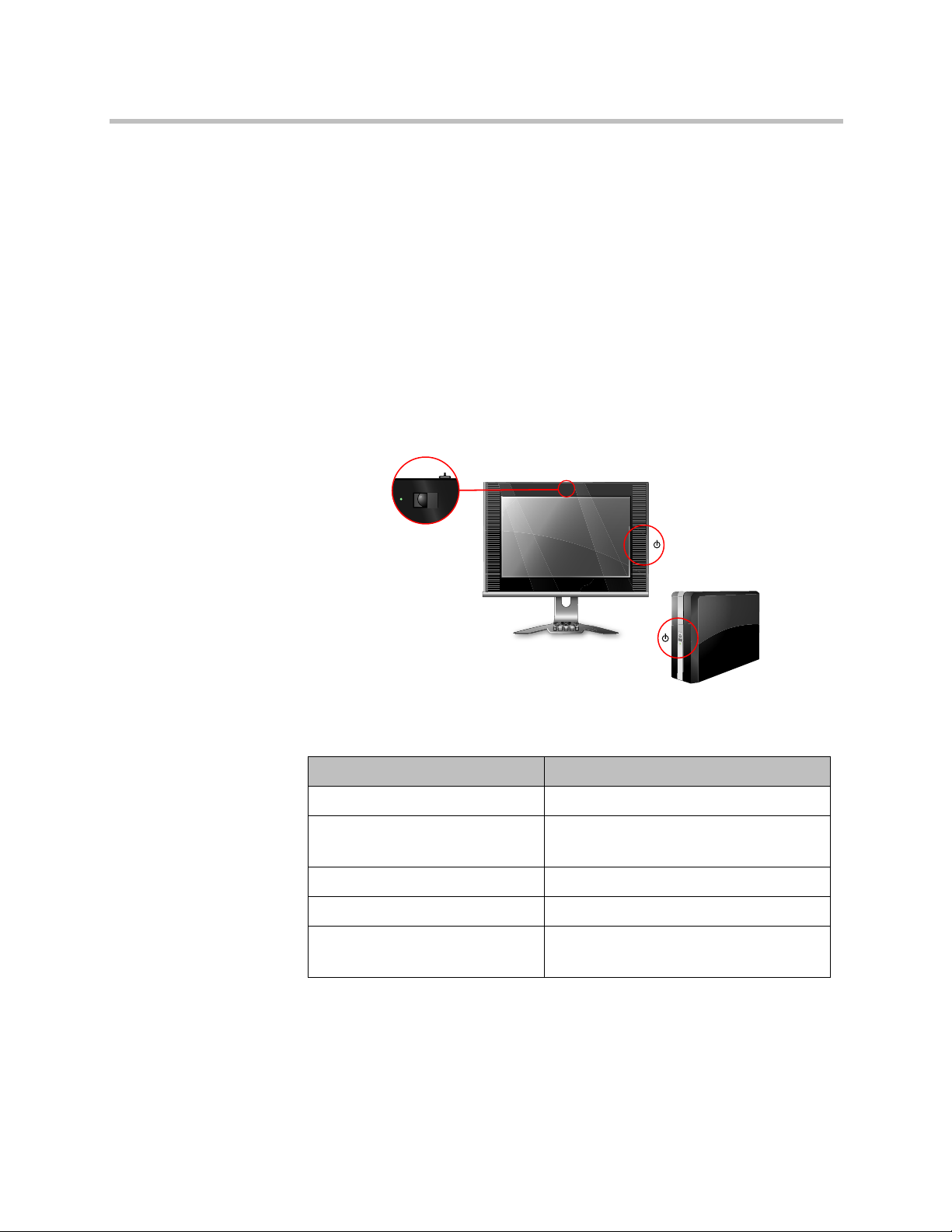
Polycom HDX 9000 Series Indicator Light
The following figure shows the location of the power switch and indicator
light.
The indicator light on the front of the Polycom HDX 9000 series system
provides this information:
Indicator Light System Status
Off System is powered off.
Steady green light System is initializing.
System is awake.
Blinking green light System received an IR (infrared) signal.
Steady amber light System is asleep.
Alternating green and amber lights System is in software update mode.
System is in factory restore mode.
Powering On the Polycom HDX 8000 Series, Polycom HDX 7000 Series, or
Polycom HDX 6000 Series Systems
To power on the Polycom HDX 8000 series, Polycom HDX 7000 series, or
Polycom HDX 6000 series system, do one of the following:
• Press the power button on the remote control.
• Press the power switch on the front of the system.
The Polycom splash screen is displayed within about 10 seconds.
1–10 Polycom, Inc.
Artisan Technology Group - Quality Instrumentation ... Guaranteed | (888) 88-SOURCE | www.artisantg.com
Page 26
Introducing the Polycom HDX Systems
To power off the Polycom HDX 8000 series, Polycom HDX 7000 series, or
Polycom HDX 6000 series system, do one of the following:
• Press and hold the power button on the remote control for 2 seconds.
• Press and hold the power switch on the front of the system for 2 seconds.
After turning the power off in this way, wait until the power light stops
flashing, which might take several seconds, before you unplug the system
from its power source.
Polycom HDX 8000 Series, Polycom HDX 7000 Series, and
Polycom HDX 6000 Series Indicator Light
The indicator light on the front of the Polycom HDX 8000 series, Polycom HDX
7000 series, and Polycom HDX 6000 series systems provides this information:
Indicator Light System Status
Off System is without power.
Steady blue light System is initializing.
Blinking blue light System received an IR (infrared) signal.
Steady amber light System is asleep.
Alternating blue and amber lights System is in software update mode.
Powering On the Polycom HDX 4000 Systems
To power on a Polycom HDX 4000 system, do one of the following:
• Press the power button on the front of the system.
• Press the power button on the side of the monitor.
The Polycom splash screen is displayed within about 10 seconds.
To power off a Polycom HDX 4000 system monitor:
>> Press the power button on the side of the monitor.
The monitor enters standby mode. The system stays powered on.
System is awake.
System is in factory restore mode.
Polycom, Inc. 1–11
Artisan Technology Group - Quality Instrumentation ... Guaranteed | (888) 88-SOURCE | www.artisantg.com
Page 27
Administrator’s Guide for Polycom HDX Systems
Monitor Power
System
Monitor Camera
To power off a Polycom HDX 4000 system, do one of the following:
• Press and hold the power button on the side of the monitor.
The monitor and the system power off.
• Press and hold the power button on the front of the system.
The monitor and the system power off.
After turning the power off in this way, wait at least 15 seconds before you
unplug the system from its power source.
Polycom HDX 4000 Systems Indicator Lights
The following figure shows the location of the power switches and indicator
lights.
1–12 Polycom, Inc.
The indicator light on the front of the Polycom HDX 4000 systems provides
this information:
Indicator Light (System) Status
Off System is without power.
Steady blue light System is initializing.
System is awake.
Blinking blue light System received an IR (infrared) signal.
Steady amber light System is asleep.
Alternating blue and amber lights System is in software update mode.
System is in factory restore mode.
Artisan Technology Group - Quality Instrumentation ... Guaranteed | (888) 88-SOURCE | www.artisantg.com
Page 28
Introducing the Polycom HDX Systems
The indicator light on the side of the Polycom HDX 4000 systems provides this
information:
Indicator Light (Monitor Power) Status
Off Monitor is powered off.
Steady blue light Monitor is powered on.
Steady amber light Monitor is in standby mode.
Rapidly blinking light Monitor is not connected correctly to the
system. Verify that the monitor is connected
correctly according to the setup sheet you
received with the system.
The indicator light next to the built-in camera in the Polycom HDX 4000
systems provides this information:
Indicator Light (Monitor Camera) Status
Off System is not in a call.
Steady green light System is in a call.
Blinking green light System is in a call with the privacy shutter
closed.
Powering the Polycom HDX 4500 System On and Off
To power on the Polycom HDX 4500 system:
>> Press the power button on the side of the monitor.
The Polycom splash screen is displayed within about 10 seconds.
To power off the Polycom HDX 4500 system:
>> Press and hold the power button on the side of the monitor.
The monitor and the system power off.
To power off the Polycom HDX 4500 system monitor:
>> Press the power button on the side of the monitor.
The monitor enters standby mode. The system stays powered on.
Polycom, Inc. 1–13
Artisan Technology Group - Quality Instrumentation ... Guaranteed | (888) 88-SOURCE | www.artisantg.com
Page 29
Administrator’s Guide for Polycom HDX Systems
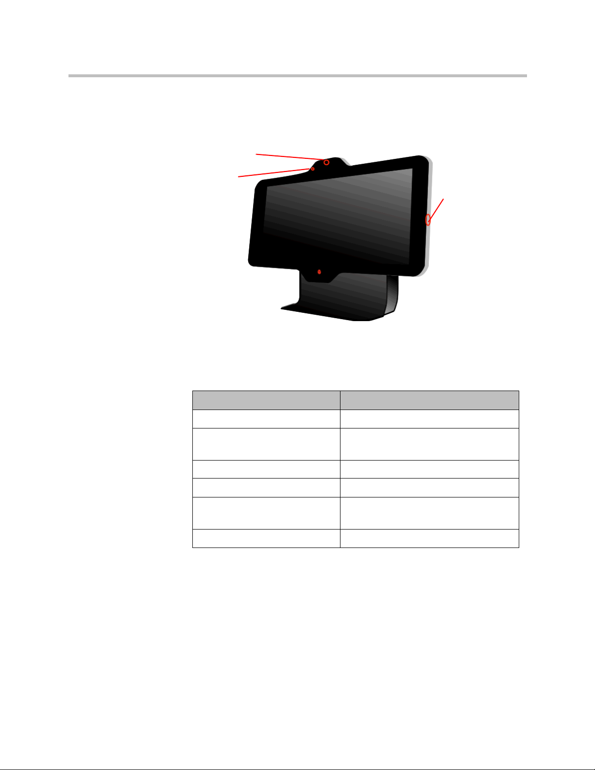
Privacy Shutter
Camera
Power
Polycom HDX 4500 System Indicator Lights
The following figure shows the location of the power switch and indicator
lights.
The Polycom HDX 4500 system does not have a separate light for the system.
The light on the right side of the monitor indicates power for the monitor and
the system.
This indicator light provides the following information:
Indicator Light (System) Status
Off System is without power.
Steady blue light System is initializing.
System is awake.
Blinking blue light System is receiving an IR signal.
Steady amber light System is asleep.
Alternating blue and amber lights System is in software update mode.
System is in factory restore mode.
Rapidly blinking amber light System is shutting down.
1–14 Polycom, Inc.
Artisan Technology Group - Quality Instrumentation ... Guaranteed | (888) 88-SOURCE | www.artisantg.com
Page 30
The indicator light next to the built-in camera in the Polycom HDX 4500
system provides this information:
Indicator Light (Monitor Camera) Status
Off System is not in a call.
Steady green light System is in a call.
Blinking green light System is in a call with the privacy shutter
Powering On the Polycom Touch Control Device
To power on the Polycom Touch Control:
1 Connect the Ethernet cable to the underside of the Polycom Touch
Control.
Introducing the Polycom HDX Systems
closed.
2 Plug the Ethernet cable into the wall outlet.
— If your room provides Power Over Ethernet, you can connect the
Ethernet cable directly to a LAN outlet.
— If your room does not provide Power Over Ethernet, you must
connect the Ethernet cable to the optional power supply adapter. Then
connect the power supply adapter to a LAN outlet and power outlet.
The power supply adapter is sold separately.
The Polycom Touch Control powers on and displays the language
selection screen.
To power off the Polycom Touch Control:
1 From the Touch Control Home screen, touch User Settings.
2 Scroll to the Power section.
3 Select Touch Control Power.
4 In the menu that appears, select Power Off the Touch Control. If you
choose to power off the Polycom Touch Control, you must disconnect
and reconnect the LAN cable to power it on again.
To wake u p the Pol y com Touch Control :
The touch control goes to sleep after 2 minutes of inactivity. Touch the screen
to wake it up.
Polycom, Inc. 1–15
Artisan Technology Group - Quality Instrumentation ... Guaranteed | (888) 88-SOURCE | www.artisantg.com
Page 31

Administrator’s Guide for Polycom HDX Systems
Power
Indicator
Polycom Touch Control Indicator Light
When the Polycom Touch Control is on, the Home button is lit.
Polycom EagleEye Director Indicator Light
The following figure shows the location of the power indicator light on the
back of the Polycom EagleEye Director.
This indicator light provides the following information:
Indicator Light Status
Steady blue light Cameras are ready.
Steady red light Cameras are powering on.
Blinking red light Factory restore on the cameras is starting.
Configuring the Polycom HDX System
Setup Wizard
When you power on your system for the first time, the setup wizard detects
the system’s IP and ISDN connections and leads you through the minimum
configuration steps required to place a call.
If you cannot see the user interface on the system’s monitor , refer to Changing the
Video Format on page 12-7.
1–16 Polycom, Inc.
Artisan Technology Group - Quality Instrumentation ... Guaranteed | (888) 88-SOURCE | www.artisantg.com
Page 32

Introducing the Polycom HDX Systems
The setup wizard allows you to set an Admin ID and password, which allows
you to limit access to the Admin Settings. The default Admin ID is
the default admin room password is the 14-digit system serial number from
the System Information screen or the back of the system. Admin and User IDs
are not case sensitive.
Make sure you can recall the room password if you set one. If you forget the
password, you must use the restore button to run the setup wizard again in order to
access the Admin Settings and reset the password. For more information, refer to
Using the Restore Button on the Polycom HD X System on page 12-2.
You can run the setup wizard or view the configuration screens in either of
these two ways.
• In the room with the system — Use the remote control to navigate the
screens and enter information. You can use the number pad on the remote
control to enter text. Point the remote control at the camera to control
Polycom HDX 8000 series, Polycom HDX 7000 series, and Polycom HDX
6000 series systems.
admin
and
Admin Settings
• From a remote location — If you know the IP address of the system, you
can access and configure the HDX system by using the HDX web interface.
For more information about using the web interface, refer to Accessing the
Polycom HDX Web Interface on page 9-1.
The setup wizard is available during initial setup, after a software update or
system reset with system settings deleted, or after using the restore button.
After you run the setup wizard, you can view or change the system’s
configuration by going to the Admin Settings in the system’s local interface or
web interface.
When a Polycom HDX system is paired with a Polycom Touch Control, the following
statements are true:
• You can change the system’s configuration using the web interface only.
• When prompted to enter the Admin Room ID and password and no Admin
Room ID is configured, you can submit a blank password.
If you enable a security profile in the setup wizard, certain configuration
settings are set and controlled automatically.
If you enable a provisioning service, any settings provisioned by the Polycom
Converged Management Application
®
(CMA®) or Polycom RealPresence®
Resource Manager system may be displayed as read-only settings in the
Polycom HDX system interface. For more information about automatic
provisioning, refer to the Polycom CMA or RealPresence Resource Manager
system documentation on the Polycom web site.
Polycom, Inc. 1–17
Artisan Technology Group - Quality Instrumentation ... Guaranteed | (888) 88-SOURCE | www.artisantg.com
Page 33

Administrator’s Guide for Polycom HDX Systems
The Polycom Touch Control has separate admin settings that allow you to
update Touch Control software and configure LAN, regional, and security
properties for the Touch Control. Refer to the following sections for more
information:
• Configuring the Polycom Touch Control LAN Properties on page 2-7.
• Configuring Polycom Touch Control Regional Settings on page 7-2.
• Configuring Admin ID and Password for the Polycom Touch Control on
page 8-11.
• Managing Polycom Touch Control Logs on page 8-35.
An admin ID and password might be configured for the Touch Control
Administration settings. The default ID is
456
.
admin
and the default password is
1–18 Polycom, Inc.
Artisan Technology Group - Quality Instrumentation ... Guaranteed | (888) 88-SOURCE | www.artisantg.com
Page 34

Networks
This guide covers network types used worldwide. Note that not all network
types are available in all countries.
Getting the Network Ready
2
Before you begin configuring the network options, you must make sure your
network is ready for video conferencing.
To begin, refer to the Network Planning Worksheets for Video Conferencing
document, available on the Polycom web site. This document contains
information you need to prepare your network, such as worksheets that will
help you order ISDN.
Polycom also offers contract high-definition readiness services. For more
information, please contact your Polycom distributor.
Connecting to the LAN
You must connect the system to a LAN to:
• Make H.323 or SIP calls
• Use a Global Directory Server
• Register with a management system
• Access the web interface
• Use People+Content™ IP
• Connect to the Polycom Touch Control
Polycom, Inc. 2–1
Artisan Technology Group - Quality Instrumentation ... Guaranteed | (888) 88-SOURCE | www.artisantg.com
Page 35

Administrator’s Guide for Polycom HDX Systems
LAN Status Lights
The LAN connector on the Polycom HDX 9000 series and Polycom HDX 6000
series has two lights to indicate connection status and traffic:
Indicator Light Connection Status
Left light off No 1000Base-T connection.
Left light green 1000Base-T connection. The light goes off each time a
Right light off No 10/100Base-T connection.
Right light green 100Base-T connection. The light goes off each time a
Right light yellow 10Base-T connection. The light goes off each time a
The LAN connector on the Polycom HDX 8000 series, Polycom HDX 7000
series, and Polycom HDX 4000 series systems has two lights to indicate
connection status and traffic:
frame is transmitted or received.
frame is transmitted or received.
frame is transmitted or received.
Indicator Light Connection Status
Left light off No 100Base-T connection.
Left light green 100Base-T connection. The light goes off each time a
Right light off No 10Base-T connection.
Right light green 10Base-T connection. The light goes off each time a
Configuring LAN Properties
In IPv4/IPv6 hybrid networks, the system tries to place calls using the IPv6
address first. If that fails, the system tries to place the call using the IPv4
address.
You can configure LAN properties for the Polycom HDX Systems and for
Polycom Touch Control Devices. Refer to Configuring Polycom HDX System
LAN Properties on page 2-3 and Configuring the Polycom Touch Control
LAN Properties on page 2-7.
frame is transmitted or received.
frame is transmitted or received.
2–2 Polycom, Inc.
Artisan Technology Group - Quality Instrumentation ... Guaranteed | (888) 88-SOURCE | www.artisantg.com
Page 36

Configuring Polycom HDX System LAN Properties
To configure Polycom HDX LAN properties:
1 Do one of the following:
— In the local interface, go to System > Admin Settings > LAN
Properties (select if necessary).
— In the web interface, go to Admin Settings > LAN Properties.
2 Configure these settings on the LAN Properties screen:
Setting Description
IP Address (IPv4) Specifies how the system obtains an IP address.
• Obtain IP address automatically — Select if the
system gets an IP address from the DHCP server on the
LAN.
• Enter IP address manually — Select if the IP address
will not be assigned automatically.
Changing this setting causes the system to restart.
Networks
IP Address If the system obtains its IP address automatically, this area
displays the IP address currently assigned to the system.
If you selected Enter IP Address Manually, enter the IP
address here. Changing the IP address causes the system
to restart.
Subnet Mask Displays the subnet mask currently assigned to the system.
If the system does not automatically obtain a subnet mask,
enter one here.
Changing this setting causes the system to restart.
Default Gateway
(IPv4)
Displays the gateway currently assigned to the system.
If the system does not automatically obtain a gateway IP
address, enter one here.
Changing this setting causes the system to restart.
Polycom, Inc. 2–3
Artisan Technology Group - Quality Instrumentation ... Guaranteed | (888) 88-SOURCE | www.artisantg.com
Page 37

Administrator’s Guide for Polycom HDX Systems
Setting Description
IP Address (IPv6) Specifies how the system obtains an IP address.
Link-Local Displays the IPv6 address used for local communication
Site-Local Displays the IPv6 address used for communication within
• Obtain IP address automatically — Select if the
system gets an IP address automatically. DHCP is not
currently supported for IPv6. When you choose this
setting, the system uses Stateless Address
Autoconfiguration (SLAAC) to obtain a global address,
unique local address (ULA), or site-local address using
router advertisements. The network routers also must be
configured appropriately to provide the advertisement
packets.
• Enter IP address manually — Select if the IP address
will not be assigned automatically.
•Off — Select to disable IPv6.
Changing this setting causes the system to restart.
within a subnet.
the site or organization.
Global Address Displays the IPv6 internet address.
Default Gateway
(IPv6)
Displays the gateway currently assigned to the system.
If the system does not automatically obtain a gateway IP
address, enter one here.
Changing this setting causes the system to restart.
Host Name Indicates the system’s DNS name.
Changing this setting causes the system to restart.
Note: Although HDX systems have a limited ability to
dynamically register a host name to a DNS server, many
DNS server deployments do not allow this type of
registration. If you intend to reach the HDX system by using
its DNS host name, you must manually register that name
with the DNS server that serves the DNS domain where the
HDX system is located.
Domain Name Displays the domain name currently assigned to the system.
If the system does not automatically obtain a domain name,
enter one here.
2–4 Polycom, Inc.
Artisan Technology Group - Quality Instrumentation ... Guaranteed | (888) 88-SOURCE | www.artisantg.com
Page 38

Networks
Setting Description
DNS Servers Displays the DNS servers currently assigned to the system.
If the system does not automatically obtain a DNS server
address, enter up to four DNS servers here.
• IPv6: Y ou can specify IPv6 DNS server addresses for IP
addresses entered manually or obtained automatically
(in the case of a system on a hybrid network that obtains
IPv4 DNS server addresses via DHCPv4).
• IPv4: You can specify IPv4 DNS server addresses only
when the IPv4 address is entered manually. When the
IPv4 address is obtained automatically, the DNS Server
addresses are also obtained automatically.
Changing this setting causes the system to restart.
LAN Speed Specify the LAN speed to use. Note that the speed you
choose must be supported by the switch.
Choose Auto to have the network switch negotiate the
speed automatically. Choosing Auto automatically sets
Duplex Mode to Auto. If you choose 10 Mbps, 100 Mbps,
or 1000 Mbps you must set Duplex Mode to Half or Full.
Note: Polycom does not support Auto for the Polycom HDX
system only or the switch only; the settings for both must be
the same.
Changing this setting causes the system to restart.
Duplex Mode Specify the duplex mode to use. Note that the Duplex mode
you choose must be supported by the switch.
Choose Auto to have the network switch negotiate the
Duplex mode automatically. Choosing Auto automatically
sets LAN Speed to Auto.
The duplex settings for both the Polycom HDX system and
the switch must be the same. Polycom recommends that you
set both to Auto. IEEE802.3 also recommends that you use
Autonegotiation to avoid network issues.
Changing this setting causes the system to restart.
Enable
EAP/802.1X
Specifies whether EAP/802.1X network access is enabled.
Polycom HDX systems support the following authentication
protocols:
• EAP-MD5
• EAP-PEAPv0 (MSCHAPv2)
• EAP-TTLS
• EAP-TLS
Identity Specifies the system’s identity used for 802.1X
authentication. This setting is available only when
EAP/802.1X is enabled. The field cannot be blank.
Password Specifies the system’s password used for some 802.1X
authentication.
Polycom, Inc. 2–5
Artisan Technology Group - Quality Instrumentation ... Guaranteed | (888) 88-SOURCE | www.artisantg.com
Page 39

Administrator’s Guide for Polycom HDX Systems
Setting Description
Enable 802.1p/Q Specifies whether VLAN and link layer priorities are enabled.
VLAN ID Specifies the identification of the Virtual LAN.This setting is
Video Priority Sets the link layer priority of video traffic on the LAN. Video
Audio Priority Sets the priority of audio traffic on the LAN. Audio traffic is
Control Priority Sets the priority of control traffic on the LAN. Control traffic is
available only when 802.1p/Q is enabled. The value can be
any number from 1 to 4094.
traffic is any RTP traffic consisting of video data and any
associated RTCP traffic. This setting is available only when
802.1p/Q is enabled. The value can be any number from 0 to
7, although 6 and 7 are not recommended.
any RTP traffic consisting of audio data and any associated
RTCP traffic. This setting is available only when 802.1p/Q is
enabled. The value can be any number from 0 to 7, although
6 and 7 are not recommended.
any traffic consisting of control information associated with a
call:
• H.323—H.225.0 Call Signaling, H.225.0 RAS, H.245,
Far End Camera Control
• SIP—SIP Signaling, Far End Camera Control, Binary
Floor Control Protocol (BFCP)
This setting is available only when 802.1p/Q is enabled. The
value can be any number from 0 to 7, although 6 and 7 are
not recommended.
Enable PC LAN
Port
Specifies whether the PC LAN port is enabled on the back of
a Polycom HDX 4000 series, Polycom HDX 7000, Polycom
HDX 8000 series, or Polycom HDX 9006 system. Disable
this setting for increased security.
The following IPv4 and IPv6 settings are available only on the web interface.
Changing any of these settings causes the system to restart.
Setting Description
Ignore Redirect
Messages
ICMP
Transmission
Rate Limit
(millisec)
2–6 Polycom, Inc.
Enables the HDX system to ignore ICMP redirect messages
from network routers. A redirect message tells the endpoint
to use a different router than the one it is using.
Specifies the minimum number of milliseconds between
transmitted ICMP “error” packets. Enter a number between 0
and 60000. The default value of 1000 signifies that the
system sends 1 packet per second. If you enter 0, the
transmission rate limit is disabled.
This setting applies only to “error” ICMP packets. This
setting has no effect on “informational” ICMP packets, such
as echo requests and replies.
Artisan Technology Group - Quality Instrumentation ... Guaranteed | (888) 88-SOURCE | www.artisantg.com
Page 40

Setting Description
Networks
Generate
Destination
Unreachable
Messages
Respond to
Broadcast and
Multicast Echo
Requests
IPv6 DAD
Transmit Count
Generates an ICMP
a packet cannot be delivered to its destination for reasons
other than network congestion.
Sends an ICMP
broadcast or multicast Echo Request, which is not
specifically addressed to the HDX system.
Specifies the number of Duplicate Address Detection (DAD)
messages to transmit before acquiring an IPv6 address. The
HDX system sends DAD messages to determine whether
the address it is requesting is already in use.
Select whether to transmit 0, 1, 2, or 3 DAD requests for an
IPv6 address.
Destination Unreachable
Echo Reply
message in response to a
Configuring the Polycom Touch Control LAN Properties
To configure Polycom Touch Control LAN settings:
1 From the Home screen, touch Administration.
2 Touch the LAN Properties tab.
message if
3 Configure the following IP Address (IPv4) settings:
Setting Description
Set IP
Address
IP Address Displays the IP address currently assigned to the Touch Control, if
Subnet Mask Displays the subnet mask currently assigned to the Touch Control.
Default
Gateway
Specifies how the Touch Control obtains an IP address.
• Obtain IP address automatically — Select if the Touch
Control gets an IP address from the DHCP server on the LAN.
• Enter IP address manually — Select if the IP address is not
automatically assigned.
the Touch Control obtains its IP address automatically.
If you selected Enter IP address manually, enter the IP address
here.
If you selected Enter IP address manually, enter the subnet
mask here.
Displays the gateway currently assigned to the Touch Control.
If you selected Enter IP address manually, enter the gateway IP
address here.
Polycom, Inc. 2–7
Artisan Technology Group - Quality Instrumentation ... Guaranteed | (888) 88-SOURCE | www.artisantg.com
Page 41

Administrator’s Guide for Polycom HDX Systems
4 Configure the following DNS setting:
Setting Description
DNS Servers Displays the DNS servers currently assigned to the Touch Control.
5 Optionally, view the general settings:
Setting Description
Duplex Mode Displays the duplex mode.
LAN Speed Displays the LAN speed.
If the Touch Control does not automatically obtain a DNS server
address, enter up to two DNS servers here.
You can specify IPv4 DNS server addresses only when the IPv4
address is entered manually. When the IPv4 address is obtained
automatically, the DNS Server addresses are also obtained
automatically.
Configuring IP Settings
Specifying H.323 Settings
If your network uses a gatekeeper, the system can automatically register its
H.323 name and extension. This allows others to call the system by entering
the H.323 name or extension instead of the IP address.
To specify H.323 settings:
1 Do one of the following
— In the local interface, go to System > Admin Settings > Network > IP
> H.323 Settings.
— In the web interface, go to Admin Settings > Network > IP Network
> H.323 Settings.
2–8 Polycom, Inc.
Artisan Technology Group - Quality Instrumentation ... Guaranteed | (888) 88-SOURCE | www.artisantg.com
Page 42

2 Configure these settings on the H.323 Settings screen:
Setting Description
Networks
Display H.323
Extension
H.323 Name Specifies the name that gatekeepers and gateways use to
H.323 Extension
(E.164)
Allows users to enter H.323 extensions separately from the
gateway ID on the Place a Call screen. If your system is
registered with a gatekeeper, this setting also displays your
H.323 extension on the home screen.
If you do not select this setting, users make gateway calls by
entering the call information in this format:
gateway ID + ## + extension
identify this system. You can make point-to-point calls using
H.323 names if both systems are registered to a gatekeeper.
The H.323 Name is the same as the System Name, unless
you change it. Your organization’s dial plan may define the
names you can use.
Lets users place point-to-point calls using the extension if both
systems are registered with a gatekeeper, and specifies the
extension that gatekeepers and gateways use to identify this
system.
Your organization’s dial plan may define the extensions you
can use.
Configuring the System to Use a Gatekeeper
A gatekeeper manages functions such as bandwidth control and admission
control. The gatekeeper also handles address translation, which allows users
to make calls using static aliases instead of IP addresses that may change each
day.
To configure the system to use a gatekeeper:
1 Do one of the following:
— In the local interface, go to System > Admin Settings > Network > IP
> H.323 Settings (select if necessary).
— In the web interface, go to Admin Settings > Network > IP Network
> H.323 Settings.
Polycom, Inc. 2–9
Artisan Technology Group - Quality Instrumentation ... Guaranteed | (888) 88-SOURCE | www.artisantg.com
Page 43

Administrator’s Guide for Polycom HDX Systems
2 Configure these settings:
Setting Description
Use Gatekeeper Select this setting to use a gatekeeper. Gateways and
H.323 Name Specifies the name that gatekeepers use to identify this
gatekeepers are required for calls between IP and ISDN.
• Off — Calls do not use a gatekeeper.
•Auto — System attempts to automatically find an
available gatekeeper.
• Specify — Calls use the specified gatekeeper. This
option must be selected to enable H.235 Annex D
Authentication.
• Specify with PIN — Calls use the specified E.164
address and require an Authentication PIN. This setting
is available only when the Avaya® option key is installed.
system. You can make point-to-point calls using H.323
names if both systems are registered to a gatekeeper.
The H.323 Name is the same as the System Name, unless
you change it. Your organization’s dial plan may define the
names you can use.
H.323 Extension
(E.164)
Specifies the extension that gatekeepers and gateways use
to identify this system.
Your organization’s dial plan may define the extensions you
can use.
Primary
Gatekeeper IP
Address
• If you chose No for the Use Gatekeeper field, the
Primary Gatekeeper IP Address field is not displayed.
• If you chose to use an automatically selected gatekeeper,
this area displays the gatekeeper’s IP address.
• If you chose to specify a gatekeeper, enter the
gatekeeper’s IP address or name (for example,
gatekeeper.companyname.usa.com, or
10.11.12.13
).
The primary gatekeeper IP address contains the IPv4 or IPv6
address with which the system registers. As part of the
gatekeeper registration process, the gatekeeper might return
alternate gatekeepers. If communication with the primary
gatekeeper is lost, the HDX system registers with the
alternate gatekeeper but continues to poll the primary
gatekeeper. If the system reest ablishes communications with
the primary gatekeeper, the HDX system unregisters from the
alternate gatekeeper and reregisters with the primary
gatekeeper.
Authentication Enables support for H.235 Annex D Authentication.
When H.235 Annex D Authentication is enabled, the H.323
gatekeeper ensures that only trusted H.323 endpoints are
allowed to access the gatekeeper.
2–10 Polycom, Inc.
Artisan Technology Group - Quality Instrumentation ... Guaranteed | (888) 88-SOURCE | www.artisantg.com
Page 44

Setting Description
User Name Specifies the user name for authentication with H.235
Annex D.
Password Specifies the password for authentication with H.235
Annex D.
Networks
Authentication
PIN
Use
PathNavigator for
Multipoint Calls
Specifies the password PIN to use for authentication with the
Avaya Communication Manager®. This setting is available
when Use Gatekeeper is set to Specify with PIN.
Lets you specify whether multipoint calls use the system’s
internal multipoint capability or the Conference on Demand
feature available with Polycom PathNavigator™,
ReadiManager SE200, or Polycom CMA systems. This
feature is available only if the system is registered with one of
these gatekeepers.
IPv6 Gatekeeper Support
Support for HDX systems to register and use H.323 gatekeepers is now
available on IPv6 networks. Polycom supports IPv6 registration and calling
scenarios when registered to the DMA IPv6 gatekeeper. Most gatekeeper
services currently available for IPv4 networks are also available on IPv6
networks, including the following:
• Direct and routed call methods
• Gatekeeper authentication
• H.323 Annex O dialing
Points to Note about IPv6-only Network Limitations:
• A Polycom Global Directory Server address cannot be configured.
• Polycom Global Management System™, Polycom ReadiManager® SE200,
Polycom CMA, and RealPresence Resource Manager systems cannot connect
to the Polycom HDX system.
• Firewall traversal is not supported in environments that use a gatekeeper.
• Conference on Demand is not available.
• Registering with an alternate gatekeeper is not supported.
• When the H.323 setting for Use Gatekeeper is Auto, IPv6 functionality is
disabled.
• Avaya gatekeepers are not supported.
Polycom, Inc. 2–11
Artisan Technology Group - Quality Instrumentation ... Guaranteed | (888) 88-SOURCE | www.artisantg.com
Page 45

Administrator’s Guide for Polycom HDX Systems
Some gatekeeper settings are read only. In the local interface go to System >
Admin Settings > Network > IP > H.323 Settings (select if necessary) or
Admin Settings > Network > IP Network > H.323 Settings in the web
interface to view the following settings:
• Current Gatekeeper IP Address
• Primary Gatekeeper IP Address
• Alternate Gatekeepers
These are gatekeepers that the system can use if the primary gatekeeper is
not available. Supported gatekeepers include the Polycom
PathNavigator™, RADVISION
Points to note about Polycom’s Conference on Demand feature:
In order to place calls using Conference on Demand, you need to:
• Register your Polycom HDX system with a Polycom gatekeeper. A Polycom
MGC™ or Polycom RMX® system must be configured with the gatekeeper to
provide the Conference on Demand feature.
• Enable Use PathNavigator for Multipoint Calls.
• Create a group in the directory (recommended).
When using Conference on Demand:
• Once the call begins, you cannot add another site to the call — even if the site
was in the call originally.
• The Polycom MGC or RMX system must have enough ports available to
complete the call.
®
, and Cisco gatekeepers.
Configuring Integration with Avaya Networks
Polycom HDX systems with an Avaya option key can use the following
features on an Avaya telephony network:
• Call forwarding (all, busy, no answer)—Configured by the Avaya
Communication Manager administrator and implemented by the user
• Call coverage—Configured by the Avaya Communication Manager
administrator
• Transfer—Implemented via flash hook and dialing digits
• Audio conference—Implemented via flash hook and dialing digits
• Call park
• Answer back
• DTMF tones for Avaya functions
Refer to the Avaya documentation and User’s Guide for Polycom HDX Systems
for information about these features.
2–12 Polycom, Inc.
Artisan Technology Group - Quality Instrumentation ... Guaranteed | (888) 88-SOURCE | www.artisantg.com
Page 46

Networks
AES Encryption is not supported for systems registered to an Avaya H.323
gatekeeper.
To install the Avaya option key:
1 Obtain a license number from Avaya, then enter that number online on
the Polycom web site at support.polycom.com, along with your Polycom
HDX system serial number. This returns a key code for the Avaya option.
2 On the Polycom HDX system go to System > Admin Settings > General
Settings > Options and enter the key code for the Avaya option.
To configure the Polycom HDX system to use Avaya network features:
1 Do one of the following:
— In the local interface, go to System > Admin Settings > Network > IP
> H.323 Settings (select if necessary).
— In the web interface, go to Admin Settings > Network > IP Network.
2 Set Use Gatekeeper to Specify with PIN.
a Enter the H.323 Extension (E.164) provided by the Avaya
Communication Manager administrator.
b Enter the Avaya Communication Manager IP address for Gatekeeper
IP Address.
c Enter the Authentication PIN provided by the Avaya
Communication Manager administrator.
3 Do one of the following:
— In the local interface, go to System > Admin Settings > Network > IP
> Call Preference (select if necessary).
— In the web interface, go to Admin Settings > Network > IP Network
> Call Preference.
4 Set Enable H.239.
5 Do one of the following:
— In the local interface, go to System > Admin Settings > General
Settings > System Settings > Call Settings (select if necessary).
— In the web interface, go to Admin Settings > General Settings >
System Settings.
6 Set Auto Answer Point-to-Point Video and Auto Answer Multipoint
Video to No.
Polycom, Inc. 2–13
Artisan Technology Group - Quality Instrumentation ... Guaranteed | (888) 88-SOURCE | www.artisantg.com
Page 47

Administrator’s Guide for Polycom HDX Systems
Configuring the System to Use a Gateway
A gateway performs code and protocol conversion between H.323 (IP), SIP,
and H.320 (ISDN), so that users on different networks can call one another. If
the system is configured to use a gateway, you must also configure it to use a
gatekeeper. For more information, refer to Configuring the System to Use a
Gatekeeper on page 2-9.
To configure the system to use a gateway:
1 Do one of the following:
— In the local interface, go to System > Admin Settings > Network > IP
— In the web interface, go to Admin Settings > Network > IP Network
2 Configure these settings:
Setting Description
Country Code Specifies the country code for the system’s location.
> H.323 Settings (select if necessary).
> H.323 Settings.
Area Code Specifies the area or city code for the system’s location.
Number Specifies the gateway’s number.
H.323 Extension
(E.164)
Gateway
Number Type
Number of
Digits in DID
Number
Number of
Digits in
Extension
Specifies the extension that identifies this system for incoming
gateway calls.
The default H.323 Extension can be changed.
Specifies the number type users enter to call this system:
• Direct Inward Dial — Users enter an internal extension to
call this system directly.
Note: If you choose this setting, you must also register
the number with the gatekeeper as an E.164 alias.
• Number + Extension — Users enter the gateway number
and the system’s extension to call this system.
Specifies the number of digits in the DID number.
The national or regional dialing plan for your location
determines the standard number of digits. For instance, the
US standard is 7 digits.
Specifies the number of digits in the extension used when
Direct Inward Dial is selected.
Your organization’s dial plan determines this number.
2–14 Polycom, Inc.
Artisan Technology Group - Quality Instrumentation ... Guaranteed | (888) 88-SOURCE | www.artisantg.com
Page 48

3 Enter a prefix or suffix for each bandwidth you want to allow for gateway
Specifying SIP Settings
If your network supports the Session Initiation Protocol (SIP), you can use SIP
to connect IP calls.
To specify SIP Settings:
1 Do one of the following:
Networks
calls.
The use of suffixes and prefixes is dependent on the gatekeeper, gateway
capability, and gateway configuration. Associating prefixes and suffixes
with particular bandwidths on your gateway can optimize the use of
bandwidth by your organization. Be sure the gateway is configured to use
the same prefixes and suffixes you define for the system.
— In the local interface, go to System > Admin Settings > Network > IP
> SIP Settings (select if necessary).
— In the web interface, go to Admin Settings > Network > IP Network
> SIP Settings.
2 Configure these settings:
If you installed the Microsoft real-time video (RTV) software option key, several of
the SIP configuration fields described in the following table are named differently to
align with Microsoft terminology.
Polycom, Inc. 2–15
Artisan Technology Group - Quality Instrumentation ... Guaranteed | (888) 88-SOURCE | www.artisantg.com
Page 49

Administrator’s Guide for Polycom HDX Systems
Setting Description
SIP Server
Configuration
Specifies whether to automatically or manually set the SIP
server’s IP address.
If you select Auto, the two server address fields that follow
cannot be edited. If you select Specify, those fields are
editable.
Registrar Server Specifies the IP address or DNS name of the SIP Registrar
Server.
• In a Microsoft Office Communications Server 2007 R2 or
Microsoft Lync Server 2010 environment, specify the IP
address or DNS name of the Office Communications
Server or Lync Server.
• If registering a remote HDX system with an Office
Communications Server Edge Server or Lync Server
Edge Server, use the fully qualified domain name of the
access edge server role.
By default for TCP, the SIP signaling is sent to port 5060 on
the registrar server. By default for TLS, the SIP signaling is
sent to port 5061 on the registrar server.
Enter the IP address and port using the following format:
<IP_Address>:<Port>
<IP_Address> can be an IPv4 address or a DNS hostname
such as
servername.company.com:6050
. Hostnames can
resolve to IPv4 or IPv6 addresses.
Note: If you have installed the RTV option key, this setting is
named Server name or IP address.
Syntax Examples:
• T o use the default port for the protocol you have selected:
10.11.12.13
• To specify a different TCP or UDP port:
10.11.12.13:5071
Enter an IPv6 address using the following format:
[<IPv6_Address>]:<Port>
An example of an IPv6 address is:
[2001:db8:85a3::8a2e:370:7334]:8032
2–16 Polycom, Inc.
Artisan Technology Group - Quality Instrumentation ... Guaranteed | (888) 88-SOURCE | www.artisantg.com
Page 50

Setting Description
Networks
Transport
Protocol
Indicates the protocol the system uses for SIP signaling.
The SIP network infrastructure in which your Polycom HDX
system is operating determines which protocol is required.
Auto enables an automatic negotiation of protocols in the
following order: TLS, TCP, UDP. This is the recommended
setting for most environments.
TCP provides reliable transport via TCP for SIP signaling.
UDP provides best-effort transport via UDP for SIP signaling.
TLS provides secure communication of the SIP signaling.
TLS is available only when the system is registered with a
SIP server that supports TLS. When you choose this setting,
the system ignores TCP/UDP port 5060.
Proxy Server Specifies the DNS name or IP address of the SIP Proxy
Server. If you leave this field blank, the Registrar Server is
used. If you leave both the SIP Registrar Server and Proxy
Server fields blank, no Proxy Server is used.
By default for TCP, the SIP signaling is sent to port 5060 on
the proxy server. By default for TLS, the SIP signaling is sent
to port 5061 on the proxy server.
The syntax used for this field is the same as for the Registrar
Server field.
Note: If you have installed the RTV option key, this setting is
hidden. In Microsoft networks, the Proxy server and the
Registrar server are always the same server, so only one
server address field is required.
User Name Specifies the SIP address or SIP name of the system, for
example, mary.smith@department.company.com. If you
leave this field blank, the system’s IP address is used for
authentication.
Notes:
• If you have installed the RTV option key, this setting is
named Sign-in Address.
• This setting is required for registration with Microsoft
Office Communications Server 2007 R2 or Microsoft
Lync Server 2010.
Domain User
Name
Specifies the name to use for authentication when registering
with a SIP Registrar Server, for example,
msmith@company.com. If the SIP proxy requires
authentication, this field and the password cannot be blank.
Notes:
• If you have installed the RTV option key, this setting is
named User Name.
• This setting is required for registration with Microsoft
Office Communications Server 2007 R2 or Microsoft
Lync Server 2010.
Polycom, Inc. 2–17
Artisan Technology Group - Quality Instrumentation ... Guaranteed | (888) 88-SOURCE | www.artisantg.com
Page 51

Administrator’s Guide for Polycom HDX Systems
Setting Description
Password Specifies the password that authenticates the system to the
Registrar Server.
Microsoft Lync
Server 2010
Domain Name Specifies the domain name used for authentication with the
Enable Network
Intrusion
Detection System
(NIDS)
Activates integration features such as the Microsoft global
directory and Office Communicator contact sharing with
presence.
Microsoft Lync Server 2010 for directory access.
Notes:
• This is a web-only setting.
• This setting appears only if Microsoft Lync Server 2010
is checked.
Activates the ability to log entries to the security log when the
system detects a possible network intrusion. This setting is
automatically enabled when Security Mode is enabled and it
cannot be changed. For more information about the types of
packets that are detected, refer to the Deployment Guide for
Maximum Security Environments.
For more information about this and other Microsoft/Polycom
interoperability considerations, refer to the Polycom Unified Communications
Deployment Guide for Microsoft Environments.
Points to note about SIP:
The SIP protocol has been widely adapted for voice over IP communications and
basic video conferencing; however, many of the advanced video conferencing
capabilities are not yet standardized. Many capabilities also depend on the SIP
server.
The following are examples of features that are not supported using SIP:
• Cascaded multipoint in SIP calls.
• Meeting passwords. If you set a meet ing password, SIP endpoints will be unable
to dial in to a multipoint call.
For more information about SIP compatibility issues, refer to the Release Notes for
Polycom HDX Systems.
Configuring SIP Settings for Integration with Microsoft Office
Communications Server 2007 R2 and Microsoft Lync Server 2010
Polycom HDX software versions 3.0.3 and later have been qualified with
Microsoft Office Communications Server 2007 R2, while HDX software
versions 3.0.5 and later have been certified with Microsoft Lync Server 2010.
Integration with Office Communications Server and Lync Server allows Office
Communicator and Polycom HDX system users to place audio and video calls
to each other.
2–18 Polycom, Inc.
Artisan Technology Group - Quality Instrumentation ... Guaranteed | (888) 88-SOURCE | www.artisantg.com
Page 52

Networks
If a Polycom HDX system is running in dynamic management mode, it cannot be
simultaneously registered with Office Communications Server or Lync Server and
the presence service provided by a CMA or RealPresence Resource Manager
system. Polycom HDX systems can obtain presence services from only one source:
Office Communications Server and Lync Server, or the presence service provided
by the CMA or RealPresence Resource Manager system.
Polycom supports the following features in Microsoft Office Communications
Server 2007 R2 and Microsoft Lync Server 2010:
• Interactive Connectivity Establishment (ICE)
• Federated presence
• Real-time video
• Call hold and resume for Lync-hosted SIP calls
In addition, Polycom supports the Centralized Conferencing Control Protocol
(CCCP) feature in Microsoft Lync Server 2010.
For more information about this and other Microsoft/Polycom
interoperability considerations, refer to the Polycom Unified Communications
Deployment Guide for Microsoft Environments.
If your organization deploys multiple Office Communications Server and
Lync Server pools, a Polycom HDX system must be registered to the same pool
to which the system's user account is assigned.
Configuring SIP Settings for Integration with the Telepresence
Interoperability Protocol (TIP)
When SIP is enabled on an HDX system that has the TIP option key, the HDX
system can interoperate with TIP endpoints.
Points to note about TIP:
• TIP is supported only on the following HDX systems:
— Polycom HDX 9006
— Polycom HDX 8000 HD with Hardware Version B
— Polycom HDX 7000 HD with Hardware Version C or D
— Polycom HDX 4500
— Polycom HDX 4000 with Hardware Version C
• HDX systems cannot host multipoint calls while in a SIP (TIP) call.
• SIP (TIP) calls must connect at a call speed of 1 Mbps or higher.
• Only TIP version 7 is supported.
• In a TIP call, only XGA content at 5 fps is supported. The following content
sources are not supported in TIP calls:
— USB content from the Polycom Touch Control
— People+Content IP
®
Polycom, Inc. 2–19
Artisan Technology Group - Quality Instrumentation ... Guaranteed | (888) 88-SOURCE | www.artisantg.com
Page 53

Administrator’s Guide for Polycom HDX Systems
For more information about Polycom support for the TIP protocol, refer to the
Polycom Unified Communications Deployment Guide for Cisco Environments.
RTV and Lync-Hosted Conference Support
To use RTV in a Lync-hosted conference, you must have the RTV option key
enabled on one of the following HDX systems:
• Polycom HDX 9006
• Polycom HDX 8000 with Hardware Version B
• Polycom HDX 7000 with Hardware Version C or D
• Polycom HDX 6000
• Polycom HDX 4500
• Polycom HDX 4000 with Hardware Version C
For more information about configuring your Lync Server video settings for
RTV, refer to the Polycom Unified Communications Deployment Guide for
Microsoft Environments.
Specifying Quality of Service
Set the Quality of Service options for the way your network handles IP packets
during video calls.
Polycom Video Error Concealment and Dynamic Bandwidth
You can handle video quality issues by enabling the PVEC (Polycom Video
Error Concealment) setting, the Dynamic Bandwidth setting, or both settings.
If both settings are enabled, Dynamic Bandwidth adjusts the Video Rate in
order to reduce packet loss to 3% or less. When the Packet Loss drops to 3% or
less, PVEC cleans up the video image on your monitor. The additional
processing power required might cause the Video Rate to drop while the
system is using PVEC. If this happens, the Call Statistics screen shows the
Video Rate Used as lower than the Video Rate. If Packet Loss is 0 for at least 10
minutes, PVEC stops operating and the Video Rate Used increases to match
the Video Rate.
If only PVEC is enabled and the system detects Packet Loss, PVEC attempts to
clean the image but the Video Rate is not adjusted. If only Dynamic Bandwidth
is enabled and the system detects Packet Loss of 3% or more, the Video Rate is
adjusted but PVEC does not clean the image.
You can view % Packet Loss, Video Rate, and Video Rate Used on the Call
Statistics screen. Press Info on the remote control during a call to get to the Call
Statistics screen.
2–20 Polycom, Inc.
Artisan Technology Group - Quality Instrumentation ... Guaranteed | (888) 88-SOURCE | www.artisantg.com
Page 54

Networks
Quality of Service Settings
To specify Quality of Service:
1 Do one of the following:
— In the local interface, go to System > Admin Settings > Network > IP
> Quality of Service (select if necessary).
— In the web interface, go to Admin Settings > Network > IP Network
> Quality of Service.
2 Configure these settings on the Quality of Service screen:
Setting Description
Type of Service Specifies your service type and lets you choose how to set the
priority of IP packets sent to the system for video, audio, and
far-end camera control:
• IP Precedence — Represents the priority of IP packets
sent to the system. The value can be between 0 and 5. If
this setting is selected, enter the value in the Type of
Service Value field.
• DiffServ — Represents a priority level between 0 and 63. If
this setting is selected, enter the value in the Type of
Service Value field.
Type of Service
Value
Maximum
Transmission
Unit Size
Enable PVEC Allows the system to use PVEC (Polycom Video Error
Enable RSVP Allows the system to use Resource Reservation Setup Protocol
Specifies the IP Precedence or Diffserv value for Video, Audio,
and Control.
• Audio—audio RTP traffic and associated RTCP traffic
• Video—video RTP traffic and associated RTCP traffic
• Control—traffic on any of the following channels:
H.323—H.225.0 Call Signaling, H.225.0 RAS, H.245, Far
End Camera Control
SIP—SIP Signaling, Far End Camera Control, Binary Floor
Control Protocol (BFCP)
Specifies the Maximum Transmission Unit (MTU) size used in
IP calls. If the video becomes blocky or network errors occur,
packets may be too large; decrease the MTU. If the network is
burdened with unnecessary overhead, packets may be too
small; increase the MTU.
Concealment) if packet loss occurs.
(RSVP) to request that routers reserve bandwidth along an IP
connection path. Both the near site and far site must support
RSVP in order for reservation requests to be made to routers
on the connection path.
Polycom, Inc. 2–21
Artisan Technology Group - Quality Instrumentation ... Guaranteed | (888) 88-SOURCE | www.artisantg.com
Page 55

Administrator’s Guide for Polycom HDX Systems
Setting Description
Dynamic
Bandwidth
Maximum
Transmit
Bandwidth
Maximum
Receive
Bandwidth
Specifies whether to let the system automatically find the
optimum line speed for a call.
Specifies the maximum transmit line speed between 64 kbps
and the system’s maximum line rate.
Specifies the maximum receive line speed between 64 kbps
and the system’s maximum line rate.
Note: The 8 Mbps Line Rate feature is only for multipoint calls.
It is not available as a maximum bandwidth.
Configuring the System for Use with a Firewall or NAT
A firewall protects an organization’s IP network by controlling data traffic
from outside the network. Unless the firewall is designed to work with H.323
video conferencing equipment, you must configure the system and the
firewall to allow video conferencing traffic to pass in and out of the network.
Firewall Settings
Network Address Translation (NAT) network environments use private
internal IP addresses for devices within the network, while using one external
IP address to allow devices on the LAN to communicate with other devices
outside the LAN. If your system is connected to a LAN that uses a NAT, you
need to enter the NAT Public (WAN) Address so that your system can
communicate outside the LAN.
To set up the system to work with a firewall or NAT:
1 Do one of the following:
— In the local interface, go to System > Admin Settings > Network > IP
> Firewall (select if necessary).
— In the web interface, go to Admin Settings > Network > IP Network
> Firewall.
2–22 Polycom, Inc.
Artisan Technology Group - Quality Instrumentation ... Guaranteed | (888) 88-SOURCE | www.artisantg.com
Page 56

Networks
2 Configure these settings on the Firewall screen:
Setting Description
Fixed Ports Lets you specify whether to define the TCP and UDP ports.
• If the firewall is not H.323 compatible, enable the Fixed
Ports setting. The Polycom HDX system assigns a
range of ports starting with the TCP and UDP ports you
specify, as shown in the following note.
Note: You must open the corresponding ports in the
firewall. In addition:
— For H.323 you must open the firewall’s TCP port
1720 to allow incoming calls.
— For SIP, open the following ports depending on the
configuration of the SIP Transport Protocol setting:
• UDP: 5060
• TCP: 5060
• TLS: 5061
• If the firewall is H.323 compatible or the system is not
behind a firewall, disable this setting.
TCP Ports
UDP Ports
Enable H.460
Firewall Traversal
NAT Configuration Lets you specify whether the system should determine the
NAT Public (WAN)
Address
Lets you specify the beginning value for the range of TCP
and UDP ports used by the system when the Fixed Ports
setting is enabled. The system automatically calculates the
ending value for the range based on the beginning value
you set. The ranges are as follows:
• TCP Ports: 6-port range, default starting port is 3230
(default range is 3230-3235)
• UDP Ports: 51-port range, default starting port is 3230
(default range is 3230-3280)
Allows the system to use H.460-based firewall traversal for
IP calls. For more information, refer to H.460 Firewall/NAT
Traversal on page 2-24.
NAT Public WAN Address automatically.
• If the system is not behind a NAT or is connected to the
IP network through a Virtual Private Network (VPN),
select Off.
• If the system is behind a NAT that allows HTTP traffic,
select Auto.
• If the system is behind a NAT that does not allow HTTP
traffic, select Manual.
Displays the address that callers from outside the LAN use
to call your system. If you chose to configure the NAT
manually, enter the NAT Public Address here.
NAT is H.323
Compatible
Polycom, Inc. 2–23
Artisan Technology Group - Quality Instrumentation ... Guaranteed | (888) 88-SOURCE | www.artisantg.com
Specifies that the system is behind a NAT that is capable of
translating H.323 traffic.
Page 57

Administrator’s Guide for Polycom HDX Systems
Setting Description
Address Displayed
in Global Directory
Enable SIP
Keep-Alive
Messages
The Enable SIP Keep-Alive Messages setting is enabled by default. However,
when an HDX system is deployed or registered in an Avaya SIP environment,
Polycom recommends that you disable the setting to allow calls to connect fully.
Lets you choose whether to display this system’s public or
private address in the global directory.
Specifies whether to regularly transmit keep-alive
messages on the SIP signaling channel and on all RTP
sessions that are part of SIP calls.
Keep-alive messages keep connections open through
NAT/Firewall devices that are often used at the edges of
both home and enterprise networks.
In environments set up behind a firewall, firewall administrators can choose
to limit access to TCP connections only. Although TCP is an accurate and
reliable method of data delivery that incorporates error-checking, it is not a
fast method. For this reason, real-time media streams often use UDP, which
offers speed but not necessarily accuracy. Within an environment behind a
firewall, where firewall administrator has restricted media access to TCP
ports, calls can be completed using a TCP connection instead of UDP.
Systems deployed outside a firewall are potentially vulnerable to unauthorized
access. Visit the Polycom Security section of the Knowledge Base at
support.polycom.com for timely security information. You can also register to
receive periodic email updates and advisories.
H.460 Firewall/NAT Traversal
You can configure Polycom HDX systems to use standards-based H.460.18
and H.460.19 firewall traversal, which allows video systems to more easily
establish IP connections across firewalls.
2–24 Polycom, Inc.
Artisan Technology Group - Quality Instrumentation ... Guaranteed | (888) 88-SOURCE | www.artisantg.com
Page 58

Gatekeeper
IP Network
System with
Enterprise Location A
Enterprise Location B
Service Provider
Polycom VBP device
Traversal Enabled
System with
Traversal Enabled
that Supports H.460.18
and H.460.19
Networks
The following illustration shows how a service provider might provide H.460
firewall traversal between two enterprise locations. In this example the
Polycom Video Border Proxy™ (VBP
of the service provider network and facilitates IP calls between Polycom HDX
systems behind different firewalls.
®
) firewall traversal device is on the edge
To use this traversal, Polycom HDX systems and firewalls must be configured
as follows:
1 Enable firewall traversal on the Polycom HDX system.
2 Register the Polycom HDX system to an external Polycom VBP device
3 Make sure that firewalls being traversed allow Polycom HDX systems
Basic Firewall/NAT Traversal Connectivity
Basic Firewall/NAT Traversal Connectivity allows HDX systems to connect to
the SIP-based RealPresence solutions using the Acme Packet Net-Net family of
Session Border Controllers (SBC). An HDX system connects to the Acme
Packet Net-Net SBC as a remote enterprise endpoint. The remote enterprise
endpoint is registered to the enterprise’s SIP infrastructure and connects to an
internal enterprise endpoint through the enterprise firewall.
a Go to System > Admin Settings > Network > IP > Firewall.
b Select Enable H.460 Firewall Traversal.
that supports the H.460.18 and H.460.19 standards.
behind them to open outbound TCP and UDP connections.
— Firewalls with a stricter rule set should allow Polycom HDX systems
to open at least the following outbound TCP and UDP ports: 1720
(TCP), 14085-15084 (TCP) and 1719 (UDP), 16386-25386 (UDP).
— Firewalls should permit inbound traffic to TCP and UDP ports that
have been opened earlier in the outbound direction.
Polycom, Inc. 2–25
Artisan Technology Group - Quality Instrumentation ... Guaranteed | (888) 88-SOURCE | www.artisantg.com
Page 59

Administrator’s Guide for Polycom HDX Systems
For details about the use and configuration of the Acme Packet Net-Net SBC
used in conjunction with this feature, refer to Deploying Polycom Unified
Communications in an Acme Packet Net-Net Enterprise Session Director
Environment.
HDX systems now also provide full mutual TLS support for SIP and XMPP
Presence connections. Full mutual TLS support gives administrators the
ability to identify and authenticate devices attempting to join conferences from
outside the enterprise network.
Connecting Polycom HDX Systems to ISDN or Other
Networks
The following network interface modules are available for some Polycom
HDX systems:
•BRI — Allows you to connect to an ISDN network using up to four BRI
lines.
•PRI — Allows you to connect to an ISDN T1 or E1 network using a PRI
line.
• V.35/RS-449/RS-530 — Allows you to connect to third-party network
equipment, including encryption equipment and RS-366 terminal
adaptors and inverse multiplexers.
If you received a network interface module with your system, you may find it
convenient to install it before positioning the system. Refer to the setup sheet
that you received with the network interface module. Make sure that the
system is powered off before you connect devices to it.
You will need the following network hardware.
Network Module Requirements
BRI • NT-1 device, if the system will be connected to a
network that provides a U interface. Do not use an
NT-1 device if your PBX network provides an S/T
interface.
• Up to 4 BRI lines that will not be shared with other
equipment.
If you connect fewer than four BRI ports on the
system’s network interface module, connect them in
ascending order, starting with port 1.
PRI
(North America and
Japan)
• PBX crossover cable, if required for your PBX.
• Channel Service Unit (CSU) — not required if you
connect the system to a PBX network.
• PRI line.
2–26 Polycom, Inc.
Artisan Technology Group - Quality Instrumentation ... Guaranteed | (888) 88-SOURCE | www.artisantg.com
Page 60

Additional device
Examples:
Quad BRI — NT-1
PRI — CSU
V.35/RS-449/RS-530 —
encryption equipment
Network
interface
module
External power
supply if using
PRI or NT-1
UPS
Power
source
Network
Polycom HDX
system
+
Additional device
Examples:
Quad BRI — NT-1
PRI — CSU
V.35/RS-449/RS-530 —
encryption equipment
Network
interface
module
External power
supply if using
PRI or NT-1
UPS
Power
source
Network
Polycom HDX
system
Network Module Requirements
Networks
PRI
(outside North America
and Japan)
Serial
V.35/RS-449/ RS-530
(with RS-366 dialing)
• 75 W coaxial adapter, if the network connection is
via a 75 W coaxial cable.
• PBX crossover cable, if required for your PBX.
• PRI line.
• Third-party network equipment and cables.
Contact your network equipment vendor to obtain the
appropriate cables for the equipment you connect to
this interface. If you use only one cable, connect it to
port 1 of the network interface module and to the
lowest-numbered port of the data co mmu ni ca tio ns
equipment.
The following diagram shows a general view of how network interface
modules are connected in Polycom HDX 9000 series systems.
The following diagram shows a general view of how network interface
modules are connected with Polycom HDX 8000 series, Polycom HDX 7000
series, and Polycom HDX 4000 series systems.
Polycom, Inc. 2–27
Artisan Technology Group - Quality Instrumentation ... Guaranteed | (888) 88-SOURCE | www.artisantg.com
Page 61

Administrator’s Guide for Polycom HDX Systems
Quad BRI Network Interface Status Lights
The network interface lights are located on the network interface module.
Interface Light State Description
Lights are off One of the following:
Green light is on The system is receiving a clock signal
Yellow light is on The system is able to make a call.
Green and yellow lights are on One of the following:
• No power is going to the system.
• The system is not connected to the
network.
• The system is not receiving a clock
signal from the network.
• The system is restarting.
from the network.
• The system is receiving a software
update.
• The system is operating normally.
PRI Network Interface Status Lights
The network interface lights are located on the network interface module.
Interface Light State Description
Lights are off No power to the system.
Red light is on or blinking The system is not connected to the
Yellow light is on or blinking A problem exists with the ISDN line.
Green light is on The system is able to make and receive
ISDN network, or a problem exists with
the ISDN line.
calls.
2–28 Polycom, Inc.
Artisan Technology Group - Quality Instrumentation ... Guaranteed | (888) 88-SOURCE | www.artisantg.com
Page 62

Serial V.35/RS-449/RS-530 Network Interface Status Lights
The network interface lights are located on the network interface module.
Interface Light State Description
Lights are off One of the following:
• No power to the system.
• The system is not communicating
with the network.
• The system is restarting.
Yellow light is on The system is receiving a clock signal
from the network (able to make a call).
Yellow and green lights are on The system is in a call.
Networks
Configuring ISDN and Other Network Interface Settings
You can configure a network interface option if the corresponding network
interface module is installed. The system automatically detects the type of
interface installed and displays only the required configuration screens.
Configuring the BRI Network Interface
Polycom HDX systems do not support multilink BRI connections.
To configure the ISDN network interface settings:
1 Do one of the following:
— In the local interface, go to System > Admin Settings > Network >
ISDN (select if necessary).
— In the web interface, go to Admin Settings > Network > ISDN.
Polycom, Inc. 2–29
Artisan Technology Group - Quality Instrumentation ... Guaranteed | (888) 88-SOURCE | www.artisantg.com
Page 63

Administrator’s Guide for Polycom HDX Systems
2 Configure these settings:
Setting Description
Enable ISDN
H.320
Number of ISDN
Channels to
Dial in Parallel
Outside Line
Dialing Prefix
Numbering
Plan
ISDN Voice
Algorithm
ISDN Switch
Protocols
Auto BRI
Configuration
Country,
Country Code
Allows this system to make H.320 (ISDN) calls.
Specifies how many channels to dial at one time.
You can specify up to 12 channels. If you experience network
problems, decrease the number.
Specifies the ISDN dialing prefix used to call outside the
network.
Select the appropriate numbering plan for your location, if it
differs from the default.
Specifies which voice algorithm (aLaw or uLaw) is used for
ISDN voice calls.
Do not change this setting unless you experience audio issues
in all ISDN voice calls.
Specifies the protocol used by your network’s switch.
Allows the NI-1 or NI-2 switch to automatically configure the
directory numbers and SPIDs.
This setting is only available if you have selected the NI-1 or
NI-2 switch protocol.
Displays the country selected as the system’s location and the
country code used for international calls to the system. To
specify the system’s location, go to System > Admin Settings
> General Settings > Location. The system automatically
supplies the country code when you specify the country.
Area Code Specifies the area code for this system’s location.
Directory
Numbers
Specifies the numbers assigned to the B1 and B2 channels for
each BRI line.
The two numbers for a line may be the same or different,
depending on the switch protocol in use.
Enable Specifies whether to enable the associated ISDN line.
If you selected Standard ETSI Euro-ISDN protocol, you must
enable all BRI lines that you expect to be active, and you must
not enable lines that will not be connected.
You may want to disable a particular line if there are problems
with the line that generate continuing error messages.
2–30 Polycom, Inc.
Artisan Technology Group - Quality Instrumentation ... Guaranteed | (888) 88-SOURCE | www.artisantg.com
Page 64

3 If you have configured the ISDN switch protocol to be AT&T 5ESS
Multipoint, NI-1, NI-2, or Nortel DMS-100, select if necessary and
enter the ISDN BRI SPIDs provided by your service provider.
After you enter the SPIDs, the system verifies them. If the system is unable
to verify the SPIDs, make sure the system is connected and that the ISDN
numbers you entered are correct.
If you do not have the SPIDs from your service provider, you can click
Start to Auto Detect SPIDs.
Configuring the PRI Network Interface
Points to note about fractional PRI:
• Assigned channels must begin with channel 1, and the channel numbers must
be consecutive.
• A D channel must be provided.
• Outbound call bandwidth must not exceed the available bandwidth.
Networks
To configure the ISDN network interface settings:
1 Do one of the following:
— In the local interface, go to System > Admin Settings > Network >
ISDN (select if necessary).
— In the web interface, go to Admin Settings > Network > ISDN.
2 Configure these settings:
Setting Description
Enable ISDN
H.320
Area Code Specifies the area code for this system’s location.
PRI Video
Number
Outside Line
Dialing Prefix
BONDING:
Calling Endpoint
Uses the Original
ISDN Number
Allows this system to make H.320 (ISDN) calls.
Specifies the ISDN number assigned to this system.
Specifies the ISDN dialing prefix used to call outside the
network.
Specifies the use of a bonding standard. Incoming bonded
calls will use the original number received to connect all
remaining lines required for the call.
Line Signaling Specifies the framing format in use.
This setting is configurable for PRI E1, read-only for PRI T1.
Polycom, Inc. 2–31
Artisan Technology Group - Quality Instrumentation ... Guaranteed | (888) 88-SOURCE | www.artisantg.com
Page 65

Administrator’s Guide for Polycom HDX Systems
Setting Description
External CSU
North America
Specifies whether this system uses an external or internal
Channel Service Unit (CSU).
only
Line Build Out
PRI T1 only
For systems using an internal CSU, indicates the output
attenuation in dB. Your service provider can provide you with
these values.
For systems using an external CSU, indicates the length (in
feet) of the RJ-45 cable that connects the PRI network
interface module to the CSU.
Switch Protocol Specifies the Network switch protocol. The available choices
are determined by the system’s country settings.
This setting is read-only for PRI E1, configurable for PRI T1.
Your ISDN service provider can tell you which protocol your
network uses. If you later change the Country setting, the
PRI switch protocols available may also change, and you may
be prompted to configure a different PRI switch protocol.
ISDN Voice
Algorithm
Specifies which voice algorithm (aLaw or uLaw) is used for
ISDN voice calls.
Do not change this setting unless you experience audio
issues in all ISDN voice calls.
Numbering Plan Select the appropriate numbering plan for your location, if it
differs from the default.
International
Specify the dialing prefix needed for international calls.
Dialing Prefix
Call-by-Call Specifies a code that the system sends to the telephone
company switch to request a special service, if such a code is
required.
Consult your telephone service provider to determine the
proper call-by-call value.
Number of ISDN
Channels to Dial
in Parallel
Specifies how many channels to dial at one time.
Y ou can specify up to 12 channels. If you experience network
problems, decrease the number.
Set this value to 1 for serial dialing. Serial dialing is not
recommended unless you have trouble connecting calls using
parallel dialing.
Restore Defaults Resets all values on this screen. This does not affect other
PRI settings.
2–32 Polycom, Inc.
Artisan Technology Group - Quality Instrumentation ... Guaranteed | (888) 88-SOURCE | www.artisantg.com
Page 66

Networks
Setting Description
PRI Line Type Displays read-only information about the system and its
Number of
Active Channels
D Channel
Location
Network Mode
Clock Source
Terminal
Endpoint ID
TEI
Line Termination
PRI E1 only
3 Select if necessary and select a channel to activate or deactivate it.
Active channels are represented by a green icon, and inactive channels
are represented by a gray icon.
configuration.
Make sure that channels are activated and deactivated only by a knowledgeable
network professional so that the system operates properly and can dial at the
desired rates.
Configuring the Serial V.35/RS-449/RS-530 Network Interface
To configure the V.35/RS-449/RS-530 network interface settings:
1 Do one of the following:
— In the local interface, go to System > Admin Settings > Network >
V.35/RS-449/RS-530 (select if necessary).
— In the web interface, go to Admin Settings > Network >
V.35/RS-449/RS-530.
2 Configure these settings:
Setting Description
Enable
V.35/RS-449/RS-530
V.35 Ports Used Specifies whether one or two lines are connected.
Allows the system to connect to a terminal adapter using
a V.35, RS-449, or RS-530 connection.
Polycom, Inc. 2–33
Artisan Technology Group - Quality Instrumentation ... Guaranteed | (888) 88-SOURCE | www.artisantg.com
Page 67

Administrator’s Guide for Polycom HDX Systems
Setting Description
RS-366 Dialing Allows users to dial calls from this system.
Clear this setting if this is a dedicated connection or if
another device is used for dialing calls.
Area Code
Port 1
Port 2
Specifies the area code and number or numbers that
other sites dial to reach this system.
If this is a dedicated connection, leave these fields blank.
Prefix Lets you specify the dialing prefix required to reach an
outside line.
Calling Profile Lets you specify what data communications equipment is
connected to the network interface. The system
automatically displays the default prefixes, suffixes, and
calling speeds required by that device.
If your device is not listed, select Custom.
Speed Lets you define the prefixes or suffixes to use for each
speed used in a Custom Calling Profile. For information
about required prefixes and suffixes, refer to the
documentation that came with the device.
If you choose a predefined Calling Profile, this information
is supplied for you.
ST Lets you specify the signaling required by the external
RT
RTS
device connected to the system. Specify normal or
inverted, as appropriate. In most cases, normal signaling
is appropriate.
CTS If your system is connected to Ascend equipment, you
DSR
may need to set CTS to Ignore.
DCD
DTR
Answer on DSR Specifies that the system should begin the call when it
detects a DSR signal.
Delayed DCD
Hangup
DTR Pulse Duration
(secs)
Specifies how long the system waits to end the call after a
DCD signal is lost (for example, during a ca ll via satellite).
Specifies how long the DTR signal goes low after the far
site hangs up. When the pulse is too short, the call may
not clear.
If your system is connected to ADTRAN equipment, you
may need to adjust DTR pulse duration.
Trigger Call on
H.320 Data
2–34 Polycom, Inc.
Specifies whether the call starts when H.320 data is
detected at the V.35 interface while set for direct connect.
Artisan Technology Group - Quality Instrumentation ... Guaranteed | (888) 88-SOURCE | www.artisantg.com
Page 68

Setting Description
Crypto Resync Allows a Polycom HDX system connected to
cryptographic equipment to signal when it loses video
synchronization during a call. The cryptographic
equipment can then resynchronize with the far site.
Networks
Use RTS Signal for
Resync Pulse
Time Between
Pulses (sec)
Pulse Width
(millisec)
Enable Broadcast
Mode
Enable
People+Content
Video Format Specifies the resolution at which video is transmitted.
Video Protocol Specifies the protocol used to transmit video. Choose the
Allows the system to send the resynchronization pulse on
the RTS signal. Select this setting if your data
communications equipment uses the V.35 or RS-449
capability of the serial V.35/RS-449/RS-530 network
interface.
Note: When you select this setting, the RTS no longer
functions as the Request To Send signal.
Specifies whether the system should set the time between
resync pulses automatically or use the number of seconds
you enter.
Specifies whether the system should set the pulse
duration automatically or use the number of milliseconds
you enter.
Enables support for H.331 broadcast transmissions from
the Polycom HDX system.
Broadcast mode enables the system to send video and
audio to many other systems, such as large satellite
networks.
Enables People+Content for broadcast mode.
lowest protocol supported by all systems in the
conference.
Audio Protocol Specifies the protocol used to transmit audio.
Frame Rate Specifies the frame rate to use.
Connecting to an Analog Phone Line
You can connect an analog phone line to a Polycom HDX 9000 series, Polycom
HDX 8000 series, Polycom HDX 4000, or Polycom HDX 4000 HD system to
make regular telephone calls with the system or to add audio-only participants
to video calls. The first analog phone or Voice Over ISDN connection does not
count toward the number of sites in a call. Additional analog phone or Voice
Over ISDN connections, as well as all H.323 audio-only and SIP audio-only
connections, do count toward the number of sites in a call.
Polycom, Inc. 2–35
Artisan Technology Group - Quality Instrumentation ... Guaranteed | (888) 88-SOURCE | www.artisantg.com
Page 69

Administrator’s Guide for Polycom HDX Systems
A connected SoundStation® IP 7000 conference phone can use this analog
phone line to make regular telephone calls when the Polycom HDX system is
configured as described in Configuring Telephony.
The country setting must be configured correctly on the Polycom HDX system to
ensure proper operation of the phone line and to comply with local telephony
regulations.
Configuring Telephony
To configure telephony options:
1 Do one of the following:
— In the local interface, go to System > Admin Settings > Network >
Telephony (select if necessary).
— In the web interface, go to Admin Settings > Network > Telephony.
2 Configure these settings on the Telephony screen:
Setting Description
Room Telephone Number Enter the telephone number of the room where the
system is located.
System Telephone
Number
Polycom HDX 9000 series
Polycom HDX 8000 series
Polycom HDX 4000 HD
Polycom HDX 4000
Outside Line Dialing
Prefix
Polycom HDX 9000 series
Polycom HDX 8000 series
Polycom HDX 4000 HD
Polycom HDX 4000
Specifies the analog phone number of the system,
including country and area codes for the system’s
location.
Specifies the dialing prefix used to call outside the
network.
To configure the analog phone line (POTS line):
1 Go to System > Admin Settings > Network > Telephony in the local
interface or go to Admin Settings > Network > Telephony in the web
interface.
2 Enter the System Telephone Number for the analog phone line.
2–36 Polycom, Inc.
Artisan Technology Group - Quality Instrumentation ... Guaranteed | (888) 88-SOURCE | www.artisantg.com
Page 70

3 Go to System > Admin Settings > Network > Call Preference in the local
interface or go to Admin Settings > Network > Call Preference in the
web interface.
4 Enable Analog Phone.
5 Go to System > Admin Settings > Network > Call Preference > in
the local interface or go to Admin Settings > Network > Call Preference
in the web interface.
6 Add Analog Phone to the Phone Dialing Order on the Network Dialing
screen.
Configuring Call Preferences
Call preferences help you manage the network bandwidth used for calls. You
can specify the default and optional call settings for outgoing calls. You can
also limit the call speeds of incoming calls.
Networks
To choose call preferences:
1 Do one of the following:
— In the local interface, go to System > Admin Settings > Network >
Call Preference (select if necessary).
— In the web interface, go to Admin Settings > Network > Call
Preference.
2 Configure these settings on the Call Preference screen:
Setting Description
H.239 Specifies standards-based People+Content data
collaboration. Enable this option if you know that
H.239 is supported by the far sites you will call. If
callers experience issues when sharing content with
other Polycom systems, disable this setting.
IP H.323 Allows the system to make IP calls.
SIP Allows the system to use SIP when connecting IP
calls.
TIP
Polycom HDX 9006
Polycom HDX 8000 HD with
Hardware Version B
Polycom HDX 7000 HD with
Hardware Versions C and D
Polycom HDX 4500
The TIP setting is displayed only when the TIP option
key has been installed.
When this setting is enabled, the HDX system uses
TIP to communicate with another TIP-enabled
system.
When the TIP setting is enabled, you can select
Preferred Speeds for TIP.
Polycom, Inc. 2–37
Artisan Technology Group - Quality Instrumentation ... Guaranteed | (888) 88-SOURCE | www.artisantg.com
Page 71

Administrator’s Guide for Polycom HDX Systems
Setting Description
Analog Phone
Polycom HDX 9000 series
Polycom HDX 8000 series
Polycom HDX 4000 HD
Polycom HDX 4000
Transcoding
Polycom HDX 9006
Polycom HDX 9004
Polycom HDX 9002
Polycom HDX 8000 series
Polycom HDX 4500
Polycom HDX 4000 HD
Allows the system to make voice-only calls to any
phone using an analog phone line.
Allows the Polycom HDX system and the endpoints to
adapt multiple environments for one multipoint call.
Specifies whether the system allows each far-end
system to connect at the best possible call rate and
audio/video algorithm. If transcoding is disabled, the
Polycom HDX system down-speeds all connections
to the same call rate.
When transcoding is enabled, the maximum
resolution used in the call is SIF (352x240)/CIF
(352x288), even if all of the endpoints in the call are
capable of higher resolutions. The maximum
transcoding resolution can be less than SIF/CIF,
based on the number and type of endpoints used in
the call, but the frame rate is always 30 fps.
HDX systems support transcoding for audio and video
algorithms, video resolution, and call rate. Polycom
HDX 7000 HD systems support transcoding for audio
algorithms and use speed matching for the call rate.
Diagnostic Mode Enables a limited operating mode that uses H.261 for
video and G.711 for audio. This mode provides
administrators with a workaround for interoperability
issues that cannot be resolved using other methods.
The Diagnostic Mode setting stays in effect until you
change it.
Diagnostic Mode disables many system features such
as content sharing, far end camera control, and
advanced audio and video algorithms. Use Diagnostic
Mode only when calling systems that do not operate
properly with these advanced features.
Note: The name of this setting changed from Basic
Mode to Diagnostic Mode.
ISDN Gateway Allows users to place IP-to-ISDN calls through a
gateway.
IP Gateway Allows users to place ISDN-to-IP or IP-to-IP calls
through a gateway.
2–38 Polycom, Inc.
Artisan Technology Group - Quality Instrumentation ... Guaranteed | (888) 88-SOURCE | www.artisantg.com
Page 72

Setting Description
Networks
Maximum Resolution
Polycom HDX 7000
Polycom HDX 6000 series
Polycom HDX 7000: Allows you to send and receive
720p people video at 15 fps for NTSC and 12.5 fps for
PAL. When this setting is enabled, the system
displays only two windows in Dual Monitor Emulation
(DME) mode.
Polycom HDX 6000 series: Allows you to send and
receive 1080p people video. When this setting is
enabled, Camera 2 is automatically set to People.
You can use People+Content IP to send content, but
sending content will result in reduced People video
quality.
For more information about maximum resolution and
call speeds, refer to Appendix C, Call Speeds and
Resolutions.
V.35/RS-449/RS-530 Allows the system to make calls through your
third-party network equipment.
This selection is only available when the system has a
V.35/RS-449/RS-530 network module installed.
ISDN H.320 Allows the system to make ISDN calls.
This selection is only available when the system has
ISDN networking capability.
Voice Over ISDN Allows the system to make voice-only calls to phones
connected to an ISDN network, such as an
organization’s PBX. The ISDN BRI must be
provisioned to support voice calls.
This selection is only available when the system has
ISDN networking capability.
Preferred Dialing Method Specifies the preferred method for dialing various call
types. If set to Auto, calls use the configured Dialing
Order. If set to Manual, the system prompts the user
to select the call type from a list when placing a call.
Notes:
• Call rollover does not occur for contacts called as
part of a group. If preferred dialing is set to Auto,
each contact in a group is called using the first
available call type it has that matches the Dialing
Order set on the system. If preferred dialing is set
to Manual, each contact is called using the first
available call type in this order: H.323, SIP,
ISDN/V.35, gateway H.320, gateway H.323,
Voice Over ISDN, then analog phone.
• When using the Polycom Touch Control, the
preferred dialing method must be set to Auto.
Polycom, Inc. 2–39
Artisan Technology Group - Quality Instrumentation ... Guaranteed | (888) 88-SOURCE | www.artisantg.com
Page 73

Administrator’s Guide for Polycom HDX Systems
Setting Description
Call Preference
Polycom HDX 9000 series
Polycom HDX 8000 series
Polycom HDX 7000 series
Polycom HDX 4000 series
Specifies whether the Polycom HDX system uses the
Video Dialing Order or the Phone Dialing Order first
when placing calls. This setting is available only when
both video and phone call types are available.
Video Dialing Order Specifies how the system places video calls to
directory entries that have more than one type of
number. It also specifies how the system places video
calls from the Place a Call screen when the call type
selection is either unavailable or set to Auto or Video.
If a call attempt does not connect, the system tries to
place the call using the next call type in the list.
This setting is available only when Preferred Dialin g
Method is set to Auto.
For more information, refer to Configuring Dialing
Order Settings on page 2-41.
Phone Dialing Order
Polycom HDX 9000 series
Polycom HDX 8000 series
Polycom HDX 7000 series
Polycom HDX 4000 HD
Polycom HDX 4000
Specifies how the system places audio calls to
directory entries that have more than one type of
number. It also specifies how the system places audio
calls from the Place a Call screen when the call type
selection is either unavailable or set to Auto or
Phone. If a call attempt does not connect, the system
tries to place the call using the next call type in the
list.
This setting is available only when Preferred Dialin g
Method is set to Auto.
For more information, refer to Configuring Dialing
Order Settings on page 2-41.
Preferred Speed for
Placing Calls
IP Calls
SIP (TIP) Calls
Determines the speeds to use for IP or SIP (TIP) calls
from this system when:
• The Call Quality selection is either unavailable or
set to Auto on the Place a Call screen
• The call is placed from the directory
If the far-site system does not support the selected
speed, the system automatically negotiates a lower
speed.
Users cannot specify a call speed when placing calls
from the Polycom Touch Control.
The SIP (TIP) Calls setting is available only when the
TIP setting is enabled.
2–40 Polycom, Inc.
Artisan Technology Group - Quality Instrumentation ... Guaranteed | (888) 88-SOURCE | www.artisantg.com
Page 74

Setting Description
Networks
Maximum Speed for
Receiving Calls
IP Calls
SIP (TIP) Calls
ISDN Video Calls (H.320)
Polycom HDX 9000 series
Polycom HDX 8000 series
Polycom HDX 7000 series
Polycom HDX 6000 series
Polycom HDX 4000 HD
Polycom HDX 4000
International ISDN Calls
Polycom HDX 9000 series
Polycom HDX 8000 series
Polycom HDX 7000 series
Polycom HDX 6000 series
Polycom HDX 4000 HD
Polycom HDX 4000
Allows you to restrict the bandwidth used when
receiving IP or SIP (TIP) calls.
If the far site attempts to call the system at a higher
speed than selected here, the call is renegotiated at
the speed specified in this field.
The SIP (TIP) Calls setting is available only when the
TIP setting is enabled.
Determines the speeds that will be used for ISDN
video calls from this system when:
• The Call Quality selection is either unavailable or
set to Auto on the Place a Call screen
• The call is placed from the directory
If the far-site system does not support the selected
speed, the system automatically negotiates a lower
speed.
Determines the speeds that will be used for
International ISDN video calls from this system when:
• The Call Quality selection is either unavailable or
set to Auto on the Place a Call screen
• The call is placed from the directory
If the far-site system does not support the selected
speed, the system automatically negotiates a lower
speed.
3 Select if necessary to go to the Call Speeds screen and specify the call
speeds to make available to users, if you are allowing them to choose
speeds on a call-by-call basis.
To make the enabled call types available on the Place a Call screen, you must
enable the Call Quality setting. For more information about this and other Home
Screen settings, refer to Customizing the Home Screen on page 7-3.
Configuring Dialing Order Settings
If the call type on the home screen is set to a specific call type, the system does
not attempt to place the call using a different call type, even if other types are
listed in Video Dialing Order or Phone Dialing Order.
You can configure the Polycom HDX system so that users can choose to place
IP-to-ISDN or ISDN-to-IP calls through a gateway.
Polycom, Inc. 2–41
Artisan Technology Group - Quality Instrumentation ... Guaranteed | (888) 88-SOURCE | www.artisantg.com
Page 75

Administrator’s Guide for Polycom HDX Systems
To allow users to place an IP-to-ISDN call through a gateway:
1 Make sure the system is registered with a gatekeeper.
2 Do one of the following:
— In the local interface, go to System > Admin Settings > Network >
— In the web interface, go to Admin Settings > Network > Call
3 If you want to allow users to place IP-to-ISDN calls through a gateway
when calling from the directory, do one of the following:
— On the Network Dialing screen, set Preferred Dialing Method to
Call Preference and enable ISDN Gateway.
Preference and enable ISDN Gateway.
Auto and select ISDN Gateway as the first choice under Video
Dialing Order. With this configuration, IP-to-ISDN calls placed from
the directory will be placed through a gateway if an ISDN number
exists. If the system is not registered with PathNavigator, the gateway
suffix/prefix must be configured for the corresponding speed on the
Gateway Setup screen at System > Admin Settings > Network > IP >
H.323 Settings. If the system is registered with PathNavigator, the
necessary suffix is added automatically when a call is placed.
— On the Network Dialing screen, set Preferred Dialing Method to
Manual. With this configuration, users can select ISDN Gateway
from the list of call types that appears when placing a call from the
directory.
To allow users to place an ISDN-to-IP call through a gateway:
1 Go to System > Admin Settings > Network > Call Preference in the local
interface or Admin Settings > Network > Call Preference in the web
interface.
2 Enable IP Gateway.
3 If you want to allow users to place ISDN-to-IP or IP-to-IP calls through a
gateway when calling from the directory, do one of the following:
— On the Network Dialing screen, set Preferred Dialing Method to
Auto and select IP Gateway as the first choice under Video Dialing
Order. With this configuration, ISDN-to-IP calls placed from the
directory will be placed through a gateway if an ISDN number and IP
extension exist. IP-to-IP calls placed from the directory will be placed
through a gateway if an IP address and IP extension exist.
— On the Network Dialing screen, set Preferred Dialing Method to
Manual. With this configuration, users can
select IP Gateway from
the list of call types that appears when placing a call from the
directory.
2–42 Polycom, Inc.
Artisan Technology Group - Quality Instrumentation ... Guaranteed | (888) 88-SOURCE | www.artisantg.com
Page 76

Monitors and Cameras
Connecting Monitors
Make sure that the system is powered off before you connect devices.
Connecting Monitors to Polycom HDX 9000 Series Systems
3
The following table shows how you can connect monitors to a Polycom
HDX 9000 series system.
Video Output Number Connector Output Formats
1 Two BNC (not
available on
Polycom
HDX 9006)
DVI-I VGA, DVI*, Component
2 Two BNC (not
available on
Polycom
HDX 9006)
DVI-I VGA, DVI*, Component
3 (VCR/DVD Player) BNC (two) S-Video, Composite
4 (Content),
Polycom HDX 9004
* Select DVI if the monitor is connected using HDMI or DVI-D.
For Monitor 1 and Monitor 2, the system may provide both dual BNC
connectors and a DVI-I connector. Only one at a time is active, based on the
output format configured for that monitor.
DVI-I VGA, DVI*, Component
S-Video, Composite
S-Video, Composite
The Polycom HDX system user interface is displayed on Monitor 1. If you
cannot see the user interface on the system’s monitor, refer to Changing the
Video Format on page 12-7.
Polycom, Inc. 3–1
Artisan Technology Group - Quality Instrumentation ... Guaranteed | (888) 88-SOURCE | www.artisantg.com
Page 77

Administrator’s Guide for Polycom HDX Systems
Connecting Monitors to Polycom HDX 8000 Series or
Polycom HDX 7000 Series Systems
The following table shows how you can connect monitors to a Polycom
HDX 8000 series system or Polycom HDX 7000 system with Hardware
Version A, B, or C.
Video Output Number Connector Output Formats
1 DVI-I VGA, DVI*, Component
2 DVI-I VGA, DVI*, Component
3 (VCR/DVD Player) S-Video S-Video, Composite
* Select DVI if the monitor is connected using HDMI or DVI-D.
The following table shows how you can connect monitors to a Polycom
HDX 7000 system with Hardware Version D.
Video Output Number Connector Output Formats
1 DVI-I VGA, DVI*, Component
2 DVI-I VGA, DVI*, Component
* Select DVI if the monitor is connected using HDMI or DVI-D.
The Polycom HDX system user interface is displayed on Monitor 1. If you
cannot see the user interface on the system’s monitor, refer to Changing the
Video Format on page 12-7.
Connecting a Monitor to Polycom HDX 6000 Series Systems
The following table shows how you can connect a monitor to a Polycom
HDX 6000 series system.
Video Output Connector Output Formats
Monitor HDMI HDMI, DVI
* Select DVI if the monitor is connected using DVI-D.
When the video output format is set to HDMI, you can get audio output from
the HDMI or RCA connectors. When the video output format is set to DVI, you
can get audio output from the RCA connectors only.
If you cannot see the user interface on the system’s monitor, refer to Changing
the Video Format on page 12-7.
3–2 Polycom, Inc.
Artisan Technology Group - Quality Instrumentation ... Guaranteed | (888) 88-SOURCE | www.artisantg.com
Page 78

Monitors and Cameras
Connecting a Monitor to a Polycom HDX 4500 System
The following table shows how you can connect a monitor to a Polycom
HDX 4500 system. Note that DVI is supported for Video-1 only on the monitor
that Polycom provides.
Video Output Number Connector Output Formats
1 DVI-I DVI
1
2
1
You can use Output 2 for a digital video recorder (DVR), but not with S-Video.
2
Select DVI if the monitor is connected using HDMI or DVI-D.
DVI-I VGA, DVI2, Component
Using a Polycom HDX 4000 Series System Monitor with a Computer
You can use the Polycom HDX 4000 series system monitor as a high-resolution
display for your computer, as shown on the quick start guide.
To use the Polycom HDX 4000 series system monitor as the monitor for a
computer:
1 Connect a cable from the DVI connector on the back of the Polycom
HDX 4000 system to the DVI or VGA connector on your computer.
2 To use the system’s built-in speakers for your computer’s audio, connect
the 3.5 mm audio cable from your computer to the audio input connector
on the Polycom HDX 4000 series system.
Configuring Monitor Settings
To configure monitors:
1 Do one of the following:
— In the local interface, go to System > Admin Settings > Monitors >
Monitors (select if necessary).
— In the web interface, go to Admin Settings > Monitors.
Polycom, Inc. 3–3
Artisan Technology Group - Quality Instrumentation ... Guaranteed | (888) 88-SOURCE | www.artisantg.com
Page 79

Administrator’s Guide for Polycom HDX Systems
2 Configure these settings on the Monitors screen:
Setting Description
Monitor 1 Specifies the monitor’s aspect ratio determined by the
Video Format Specifies the monitor’s format. For a list of available
HDX system:
•4:3 — Regular TV monitor
•16:9 — Wide-screen monitor
formats, refer to the information for your system in
Connecting Monitors on page 3-1.
Note: If you use 16:9, you might also need to set up the
monitor for full-screen display if the monitor does not
automatically do so. In the monitor’s setup menu,
choose the setting that stretches the picture uniformly
without clipping the edges, which is usually called Full,
Wide screen, or 16x9.
Use this setting: Not this setting:
Resolution Specifies the resolution for the monitor.
Output Upon Screen
Saver Activation
Specifies the screen saver output for Monitor 1.
Specifies whether black video or no signal is sent to the
monitor when the system goes to sleep and the screen
saver activates.
Select Black if you want to display screen saver text.
This is the recommended setting to prevent burn-in for
TV monitors.
Select No Signal if you want the display to react as if it
is not connected when the system goes to sleep. This is
the recommended setting for VGA monitors and
projectors, as well as Polycom HDX media carts with
1080p displays.
3–4 Polycom, Inc.
Artisan Technology Group - Quality Instrumentation ... Guaranteed | (888) 88-SOURCE | www.artisantg.com
Page 80

Setting Description
Monitors and Cameras
PIP
Polycom HDX 9006
Polycom HDX 9004
Polycom HDX 9002
Polycom HDX 9001
Polycom HDX 8000 HD
Polycom HDX 7000 HD
Polycom HDX 7000
Polycom HDX 6000 HD
Display Near Video
Display Far Video
Display Content
Polycom HDX 9006
Polycom HDX 9004
Polycom HDX 9002
Polycom HDX 9001
Polycom HDX 8000 HD
Polycom HDX 7000 HD
Polycom HDX 7000
Polycom HDX 4000 HD
Polycom HDX 4000
Specifies PIP (Picture-in-Picture) behavior:
•On — The PIP window stays on.
• Camera — The PIP window is displayed when the
call is first connected and when a user moves the
camera, uses presets, or switches to a different
camera source.
•Off — The PIP window is not displayed.
User control: Users can turn the PIP on or off and
change its location on the screen using
Display on
the remote control. If the Polycom HDX system is p aired
with a Polycom Touch device, users can turn the PIP on
or off and change its location by touching Layout, and
selecting the desired layout from the Call screen of the
Polycom Touch Control.
Out of a call: Users can turn the PIP on or off when the
HDX system is not in a call. This is especially useful
when users are showing content and the near-site video
PIP window is displayed over the content.
Whenan
HDXsystemispairedwithaPolycomTouch
Control,isoutofacall,andissharingcontent,the
LayoutoptionisavailableontheShowcontent
screen.
for Polycom HDX Systems.
Specifies whether to display near video, far video, and
content on this monitor.
For more information, refer to the User’s Guide
Shrink Content For monitors configured for content, specifies whether to
shrink content to fit the monitor. If selected, the content
is shrunk to fit.
Dual Monitor
Emulation
Polycom HDX 9006
Polycom HDX 9004
Polycom HDX 9002
Polycom HDX 9001
Polycom HDX 8000 HD
Polycom HDX 7000 HD
Polycom HDX 7000
Polycom HDX 4000 HD
with Hardware Version C
Polycom, Inc. 3–5
Artisan Technology Group - Quality Instrumentation ... Guaranteed | (888) 88-SOURCE | www.artisantg.com
Specifies whether the system can show multiple views
on a single display. If content is being viewed, different
views can be displayed by pressing Display on the
remote control.
If the Polycom HDX system is paired with a Polycom
Touch device and content is being viewed, touch
Layout, and select the desired view from the Call
screen of the Polycom Touch Control.
For more information, refer to Using Dual Monitor
Emulation on page 3-10.
Page 81

Administrator’s Guide for Polycom HDX Systems
Setting Description
Monitor 2
Polycom HDX 9006
Polycom HDX 9004
Polycom HDX 9002
Polycom HDX 9001
Polycom HDX 8000 HD
Polycom HDX 7000 HD
Polycom HDX 7000
Polycom HDX 4500
Video Format
Polycom HDX 9006
Polycom HDX 9004
Polycom HDX 9002
Polycom HDX 9001
Polycom HDX 8000 HD
Polycom HDX 7000 HD
Polycom HDX 7000
Polycom HDX 4500
Specifies the second monitor’s aspect ratio:
•Off — Select if you do not have a second monitor.
•4:3 — Select if you are using a regular TV monitor
as the second monitor.
•16:9—Select if you are using a wide-screen monitor
as the second monitor. On the monitor, select the
display mode that uniformly stretches the video from
side to side, which is usually called Full, Wide
screen, or 16x9.
The following setting is unavailable on Polycom
HDX 9004, HDX 9002, HDX 9001, and HDX 4500
systems:
• Monitor 1 Image—Select to display the same
image that is displayed on Monitor 1.
Specifies the monitor’s format. For a list of available
formats, refer to the information for your system in the
previous section of this chapter, Connecting Monitors on
page 3-1.
Note: If you select 16:9, you will also need to set up the
monitor for full-screen display. In the monitor’s setup
menu, choose the setting that stretches the picture
uniformly without clipping the edges, which is usually
called Full, Wide screen, or 16x9.
Use this setting: Not this setting:
Shrink Content For monitors configured for content, specifies whether to
shrink content to fit the monitor. If selected, the content
is shrunk to fit.
Resolution Specifies the resolution for the monitor.
Output Upon Screen
Saver Activation
Specifies the screen saver output for Monitor 2.
Specifies whether black video or no signal is sent to the
monitor when the system goes to sleep and the screen
saver activates.
Select Black if you want to display black video. This is
the recommended setting to prevent burn-in for TV
monitors.
Select No Signal if you want the display to react as if it
is not connected when the system goes to sleep. This is
the recommended setting for VGA monitors and
projectors, as well as Polycom HDX media carts with
1080 displays.
3–6 Polycom, Inc.
Artisan Technology Group - Quality Instrumentation ... Guaranteed | (888) 88-SOURCE | www.artisantg.com
Page 82

Setting Description
Monitors and Cameras
Display Near Video
Display Far Video
Display Content
Polycom HDX 9006
Polycom HDX 9004
Polycom HDX 9002
Polycom HDX 9001
Polycom HDX 8000 HD
Polycom HDX 7000 HD
Polycom HDX 7000
Polycom HDX 4000 HD
Polycom HDX 4000
Monitor 3 (VCR/DVD)
Polycom HDX 9006
Polycom HDX 9004
Polycom HDX 9002
Polycom HDX 9001
Polycom HDX 8000 HD
Polycom HDX 7000 HD w/
Hardware Versions A,B,C
Polycom HDX 7000
Specifies whether to display near video, far video, and
content on this monitor.
Specifies the aspect ratio for recording.
•Off — Select if you do not have a VCR or DVD
player connected to record video conferences.
•4:3 — Select to record for playback on a standard
monitor.
•16:9—Select to record for playback on a
wide-screen monitor, if your recording device has
this capability.
Note (Polycom HDX 9006, Polycom HDX 8000 series,
and Polycom HDX 7000 series systems): The video
format and resolution of Monitor 1 and Monitor 2 affect
the output sent to Monitor 3, as follows:
• When Monitor 1 and Monitor 2 are both on and are
both set to VGA (1920 x 1080 or 1280 x 720), DVI
(1920 x 1080 or 1280 x 720), or Component (NTSC
only), you can choose either Monitor 1 Image or
Monitor 2 Image as the output to Monitor 3
(VCR/DVD).
• When Monitor 1 and Monitor 2 are both on but only
one of them is set to VGA (1920 x 1080 or 1280 x
720), DVI (1920 x 1080 or 1280 x 720), or
Component (NTSC only), the output to Monitor 3
(VCR/DVD) is set to the image from that monitor.
• When Monitor 1 and Monitor 2 are both on but
neither is set to VGA (1920 x 1080 or 1280 x 720),
DVI (1920 x 1080 or 1280 x 720), or Component,
Monitor 3 is disabled.
• If Monitor 2 is disabled, Monitor 3 is fully
configurable and independent of Monitor 1.
Polycom, Inc. 3–7
Artisan Technology Group - Quality Instrumentation ... Guaranteed | (888) 88-SOURCE | www.artisantg.com
Page 83

Administrator’s Guide for Polycom HDX Systems
Setting Description
Video Format
Polycom HDX 9006
Polycom HDX 9004
Polycom HDX 9002
Polycom HDX 9001
Polycom HDX 8000 HD
Polycom HDX 7000 HD w/
Hardware Versions A,B,C
Polycom HDX 7000
Specifies the VCR or DVD player’s format. For a list of
available formats, refer to the information for your
system in the previous section of this chapter,
Connecting Monitors on page 3-1.
Shrink Content For monitors configured for content, specifies whether to
shrink content to fit the monitor. If selected, the content
is shrunk to fit.
VCR/DVD Record
Source
Polycom HDX 9006
Polycom HDX 9004
Polycom HDX 9002
Polycom HDX 9001
Polycom HDX 8000 HD
Polycom HDX 7000 HD w/
Hardware Versions A,B,C
Polycom HDX 7000
Output Upon Screen
Saver Activation
Polycom HDX 9006
Polycom HDX 9004
Polycom HDX 9002
Polycom HDX 9001
Polycom HDX 8000 HD
Polycom HDX 7000 HD
Polycom HDX 7000
Specifies the video source to be recorded to videotape
or DVD.
If Far is enabled, the recorded video will switch to the
current far site speaker. If both Near and Far are
enabled, the recorded video will switch between near
and far sites depending on the current speaker. If
Content is enabled, any content sent during the call is
recorded.
Specifies the screen saver output for a VCR or DVD
player.
Specifies whether black video or no signal is sent to the
VCR or DVD player when the system goes to sleep and
the screen saver activates.
Select Black if you want to send black video.
Select No Signal if you want the VCR or DVD player to
react as if it is not connected when the system goes to
sleep.
Note (Polycom HDX 8000 series and Polycom
HDX 7000 series systems): When VCR/DVD Record
Source is set to Monitor 1 Image or Monitor 2 Image,
the screen saver setting for Monitor 3 is the same as for
that other monitor.
Monitor 4
Polycom HDX 9004
Specifies the fourth monitor’s aspect ratio:
•Off — Select if you do not have a fourth monitor.
•4:3 — Select if you are using a regular TV monitor
as the fourth monitor.
•16:9—Select if you are using a wide-screen monitor
as the fourth monitor. On the monitor, select the
display mode that uniformly stretches the video from
side to side, which is usually called Full, Wide
screen, or 16x9.
3–8 Polycom, Inc.
Artisan Technology Group - Quality Instrumentation ... Guaranteed | (888) 88-SOURCE | www.artisantg.com
Page 84

Setting Description
Monitors and Cameras
Video Format
Polycom HDX 9004
Resolution
Polycom HDX 9004
Output Upon Screen
Saver Activation
Polycom HDX 9004
Specifies the format for Monitor 4. For a list of available
formats, refer to the information for your system in the
previous section of this chapter, Connecting Monitors on
page 3-1.
Note: If you use 16:9, you might also need to set up the
monitor for full-screen display. In the monitor’s setup
menu, choose the setting that stretches the picture
uniformly without clipping the edges, which is usually
called Full, Wide screen, or 16x9.
Specifies the resolution for Monitor 4.
Specifies the screen saver output for Monitor 4:
Specifies whether black video or no signal is sent to the
monitor when the system goes to sleep and the screen
saver activates.
Select Black if you want to display black video. This is
the recommended setting to prevent burn-in for TV
monitors.
Select No Signal if you want the display to react as if it
is not connected when the system goes to sleep. This is
the recommended setting for VGA monitors and
projectors, as well as Polycom HDX media carts with
1080p displays.
Display Content
Polycom HDX 9004
Specifies that content is displayed on Monitor 4.
Shrink Content For monitors configured for content, specifies whether to
shrink content to fit the monitor. If selected, the content
is shrunk to fit.
People Video
Adjustment, Content
Video Adjustment
Specifies the adjustment made to people video and
content video images.
•None—Preserves the aspect ratio of the source
video. The image is scaled (if necessary) to the
largest supported resolution that fits on the display
without cropping. Extra areas on the display are
filled with black borders.
• Stretch—Does not preserve aspect ratio. The
image is scaled horizontally and vertically to exactly
match the resolution of the display.
• Zoom—Preserves the aspect ratio of the source
video. The image is scaled to exactly match one of
the display dimensions while matching or exceeding
the other display dimension. The image is centered
and cropped.
Display Icons in a Call Specifies whether to display all on-screen graphics,
including icons and help text, during calls.
Polycom, Inc. 3–9
Artisan Technology Group - Quality Instrumentation ... Guaranteed | (888) 88-SOURCE | www.artisantg.com
Page 85

Administrator’s Guide for Polycom HDX Systems
Setting Description
Screen Saver Wait
Time
Using Dual Monitor Emulation
Dual Monitor Emulation is available on Polycom HDX 9000 series, Polycom
HDX 8000 series, Polycom HDX 7000 series, Polycom HDX 6000 series,
Polycom HDX 4500, and Polycom HDX 4000 HD with Hardware Version C
systems.
For the Polycom HDX 4500 system, Dual Monitor Emulation is an internal featur e.
The feature does not appear with the Monitor settings and it has no settings you
can change.
Dual Monitor Emulation is designed for rooms or offices with one monitor
only. Users see both near and far sites on one monitor in two different
windows. During presentations, users see content and the near and far sites.
What you see during a call can depend on factors such as the Polycom HDX
system monitor configuration, the number of sites in the call, and whether
content is being shared.
Specifies how long the system remains awake during
periods of inactivity. The default is 3 minutes. If the
system requires users to log in, the screen saver timeout
also logs out the current user.
Setting this option to Off prevents the system from goi ng
to sleep. To prevent image burn-in, specify 3 minutes or
less.
Note: The screen saver feature is disabled during the
setup wizard. To prevent image burn-in, complete the
setup wizard promptly.
The following systems show only two windows in Dual Monitor Emulation: Polycom
HDX 9006, Polycom HDX 8000 HD with Hardware Version B, Polycom HDX 7000
series with Hardware Version C or D, Polycom HDX 6000 series, Polycom
HDX 4500, and Polycom HDX 4000 HD with Hardware Version C.
3–10 Polycom, Inc.
Artisan Technology Group - Quality Instrumentation ... Guaranteed | (888) 88-SOURCE | www.artisantg.com
Page 86

Examples of Dual Monitor Emulation
Far site Near site
Call connects
Near and far site are the same size and
appear side by side.
Near site presses Display
Size of far site window increases.
Near site presents to far site
Content, near site, and far site are
displayed in dual monitor emulation mode.
Monitors and Cameras
Using Dual Monitor Emulation in a Call
During calls using Dual Monitor Emulation, users can press the Display
button on the remote control to scroll through the following screen layouts:
For information about using Dual Monitor Emulation in a call when the Polycom
HDX system is paired with a Polycom Tou c h Control, refer to the User’s Guide for
Polycom HDX Systems and Polycom Touch Control Device.
1 Near and far sites, same size, side by side
2 Far site big, near site small
3 Near site big, far site small
4 Near site, full screen
5 Far site, full screen
The last layout viewed is used for the next call.
Polycom, Inc. 3–11
Artisan Technology Group - Quality Instrumentation ... Guaranteed | (888) 88-SOURCE | www.artisantg.com
Page 87

Administrator’s Guide for Polycom HDX Systems
Configuring Multipoint Viewing Modes
To configure multipoint viewing modes:
1 Do one of the following:
— In the local interface, go to System > Admin Settings > Monitors >
Multipoint Setup.
— In the web interface, go to Admin Settings > Monitors > Multipoint
Setup.
2 Configure this setting:
Setting Description
Multipoint Mode Video images from multiple sites can be automatically
combined on one screen in a display know as continuous
presence.
uninterrupted for at least 15 seconds, that site appears in
presentation mode.
Auto — The view switches between continuous
presence and full screen, depending on the
interaction between the sites.
If multiple sites are talking at the same time,
continuous presence is used. If one site speaks
Discussion — Multiple sites are displayed in
continuous presence. The current speaker’s
image is highlighted.
Presentation — The speaker sees continuous
presence while the other sites see the speaker in
full screen.
Full Screen — The site that is speaking is
shown in full screen to all other sites. The current
speaker sees the previous speaker.
What you see during a multipoint call can depend on factors such as the
Polycom HDX system monitor configuration, the number of sites in the call,
the speed of the call, whether content is shared, and whether dual monitor
emulation is used. The multipoint viewing mode on the host system is the
mode used in the call.
During SD multipoint calls that include more than four sites, the Polycom
HDX system can display the site that is hosting the conference along with the
last three sites where people spoke. In HD multipoint calls, the Polycom
HDX 9004 can display up to eight sites in continuous presence. For more
information about HD and SD multipoint, refer to HD and SD Multipoint Calls
on page 3-40.
3–12 Polycom, Inc.
Artisan Technology Group - Quality Instrumentation ... Guaranteed | (888) 88-SOURCE | www.artisantg.com
Page 88

Monitors and Cameras
If Polycom StereoSurround™ is enabled, multipoint calls in continuous
presence provide a stereo effect. This stereo effect matches a far site’s audio to
its location on the display.
Points to note about Discussion mode:
• T o correctly display Discussion mode, you must select both Near and Far video
sources for Monitor 1.
• To correctly display Discussion mode for multipoint calls with three far sites
shown on two monitors, you must select both Near and Far video sources for
Monitor 1, and clear Far for Monitor 2.
• You cannot display Discussion mode on Monitor 2.
• For multipoint calls using a Polycom MGC bridge, set People Video
Adjustment and Content Video Adjustment to None in order to properly
display Discussion mode on a 16x9 monitor.
To select video sources, use the Display Near Video, Display Far Video,
and Display Content settings on the Monitors screens.
For more information about multipoint calls, refer to Experiencing
High-Definition Video Conferencing on page 3-38 and Configuring
Multipoint Calling on page 6-3.
Adjusting the Monitor’s Color Balance, Sharpness, and Brightness
In most cases, the monitor you connect to your Polycom HDX 9000 series,
Polycom HDX 8000 series, or Polycom HDX 7000 series system may be set to
a configuration that is appropriate for video conferencing applications.
Depending on your environment and model of monitor, however, the video
may exhibit one of these problems:
• Picture is too dark or too bright
• Colors appear faded
• Picture has too much of one color — for example, the picture may appear
greenish
• Picture has blocky or softened edge detail
If you notice any of these problems, adjust the monitor’s color balance,
sharpness, and brightness until the display seems acceptable. Use the video
diagnostics test as described in the following steps, or purchase a calibration
program DVD tool to help you fine-tune the display settings.
If you are using a Polycom HDX media cart or Polycom HDX Executive Collection,
select the Polycom menu option on the monitor to optimize the display for Polycom
video.
Polycom, Inc. 3–13
Artisan Technology Group - Quality Instrumentation ... Guaranteed | (888) 88-SOURCE | www.artisantg.com
Page 89

Administrator’s Guide for Polycom HDX Systems
To adjust the monitor for natural color:
1 Do one of the following:
— In the local interface, go to System > Diagnostics > Video.
— In the web interface, go to Diagnostics > Video.
2 Select the color bars icon to display the color bar test screen.
3 Adjust the color using the monitor’s controls for color, contrast, and
brightness. Your monitor may also have controls for tint and
temperature.
The colors from left to right should be white, yellow, cyan, green,
magenta, red, and blue. Make sure that the white is not tinted red, green,
or blue, and that the red is not tinted pink or orange.
Polycom HDX 4000 series displays are calibrated at the factory and do not require
color adjustment. You can make the Polycom HDX 4000 series display brighter or
dimmer using the + and - controls on the side of the monitor.
4 When the colors look right on the test screen, press Near until you see
video of the room.
5 If the color appears natural, you do not need to make further
adjustments.
If the color still needs adjustment, use the monitor’s controls to make small
adjustments until the picture appears natural.
Preventing Monitor Burn-In
Monitors and Polycom HDX systems provide display settings to help prevent
image burn-in. Plasma televisions can be particularly vulnerable to this
problem. Refer to your monitor’s documentation or manufacturer for specific
recommendations and instructions. The following guidelines help prevent
image burn-in:
• For monitors that support low-power mode when no signal is present on
the monitor input, set Output upon Screen Saver Activation to No
Signal. For example, use the No Signal setting on VGA monitors and
monitors provided by Polycom with native 1080 resolution. Otherwise, set
Output upon Screen Saver Activation to Black.
• Use the monitor’s burn-in prevention features, if available.
• Ensure that static images are not displayed for long periods.
• Set the Screen Saver Wait Time to 3 minutes or less.
3–14 Polycom, Inc.
Artisan Technology Group - Quality Instrumentation ... Guaranteed | (888) 88-SOURCE | www.artisantg.com
Page 90

• To keep the screen clear of static images during a call, disable the
following settings:
— Display Icons in a Call. For more information, refer to the settings
— Display Time in Call. For more information, refer to the settings table
— Far Site Name Display Time. For more information, refer to the
• Be aware that meetings that last more than an hour without much
movement can have the same effect as a static image.
• Consider decreasing the monitor’s sharpness, brightness, and contrast
settings if they are set to their maximum values.
Connecting Cameras
Monitors and Cameras
table described in Configuring Monitor Settings on page 3-3.
described in Configuring Call Settings on page 6-1.
settings table described in Configuring Call Settings on page 6-1.
Polycom EagleEye HD
Polycom HDX 9000 series, Polycom HDX 8000 series, and Polycom HDX 7000
series systems provide inputs for multiple PTZ cameras. You can use the
RS-232 serial port on the system to control supported non-Polycom cameras or
cameras not connected to a main camera input.
Polycom HDX 8000 series, Polycom HDX 7000 series, and Polycom HDX 6000
series systems must be connected to a camera with an IR receiver to receive
signals from the remote control. Be sure to point the remote control at the
camera to control those Polycom HDX systems. Refer to the “Interoperability”
section of the current HDX system release notes for a list of supported cameras
with IR receivers.
If you use a Sony RS-232 cable for PTZ control of a Sony camera, the built-in IR
receiver might not map to the correct pin on the Polycom HDCI Breakout adapter. If
you experience this problem, use the Polycom HDX HDCI-Sony cable to get the
correct mapping.
You can use the Polycom EagleEye™ HD camera with all Polycom HDX
systems. Polycom EagleEye HD cameras provide 720p resolution.
When connecting a Polycom EagleEye HD camera to video input 2 on a Polycom
HDX 9000 series or Polycom HDX 8000 series system, use only the approved
Polycom UL Listed adaptor, Class 2 or LPS not exceeding 12 Volts, 3.33 Amps
(part number 1465-52733-040). Verify the polarity of the power supply as shown on
the Polycom camera next to the power supply input.
Polycom, Inc. 3–15
Artisan Technology Group - Quality Instrumentation ... Guaranteed | (888) 88-SOURCE | www.artisantg.com
Page 91

Administrator’s Guide for Polycom HDX Systems
Polycom EagleEye 1080
You can use the Polycom EagleEye 1080 camera for Polycom HDX systems
with the 1080p Resolution option installed if you want to send and receive
1080p video. You can also use the Polycom EagleEye 1080 with systems that
do not have the 1080p Resolution option, to see local video in 1080 format.
When connecting a Polycom EagleEye 1080 camera to any input on a Polycom
HDX system, use the cable and power supply that come with the camera. You must
always use the power supply because the Polycom HDX EagleEye 1080 camera
does not receive power from the Polycom HDX system.
Polycom EagleEye View
The Polycom EagleEye View camera is a manual-focus, electronic pan, tilt, and
zoom (EPTZ) camera that includes built-in stereo microphones and a privacy
shutter. The Polycom EagleEye View is available with the Polycom
HDX 6000 HD system as the system camera and the main microphone. You
can also use it with the Polycom HDX 9000 series, Polycom HDX 8000 series,
and Polycom HDX 7000 series systems. For more information about the
Polycom EagleEye View microphones, refer to Using the Polycom EagleEye
View Microphones on page 4-3.
Polycom EagleEye II
When connecting a Polycom EagleEye View camera, use the brown cable that
comes with the camera if you want to use the camera’s built-in microphones. Other
cables may not carry the audio signals.
You can install the Polycom EagleEye View in a base-down orientation or inverted.
To change the camera’s orientation after installation, disconnect all cables attached
to the camera. Then install the camera with the preferred orientation and reconnect
the camera.
The Polycom EagleEye View camera can provide 1080i video to the Polycom
HDX 9006, Polycom HDX 8000 series, Polycom HDX 7000 series, and Polycom
HDX 6000 series systems.
To use the Polycom EagleEye View camera, systems must be running HDX
software version 2.6 or later.
The Polycom EagleEye II camera can provide 1080i 50/60 fps for HDX
systems.
The Polycom EagleEye II camera is not supported on Polycom HDX 9004, Polycom
HDX 9002, or Polycom HDX 9001 systems.
3–16 Polycom, Inc.
Artisan Technology Group - Quality Instrumentation ... Guaranteed | (888) 88-SOURCE | www.artisantg.com
Page 92

To use the Polycom EagleEye II camera, systems must be running software
version 2.6.1 or later.
Polycom EagleEye III
The Polycom EagleEye III camera can provide 1080i 60/50 fps, 1080p 60 fps,
and 720p 60/50 fps resolutions on all Polycom HDX room systems.
To use the Polycom EagleEye III camera, systems must be running HDX
software version 3.0.1 or later.
Polycom EagleEye Director
The EagleEye Director is a high-end device that works in conjunction with a
Polycom HDX system to provide accurate close-up views of the person who is
speaking. The EagleEye Director also provides smooth transitions between the
close-up view of the person who is speaking and the room view.
The EagleEye Director uses a dual-camera system. While one camera tracks
the person who is speaking, the other camera captures the room view. The
EagleEye Director shows the room view while the camera moves from one
speaker to another. When the tracking camera locates a person who is
speaking, the EagleEye Director camera switches to a close-up of that person.
By providing automatic and intelligent views in various speaking scenarios
during a conference, the EagleEye Director delivers a user experience similar
to a newscast video production.
Monitors and Cameras
EagleEye Director is supported on the following Polycom systems:
• HDX 9000 series
• HDX 8000 series
• HDX 7000 series
• HDX 6000 series
To use the Polycom EagleEye Director, HDX systems must be running HDX
software version 3.0.1 or later. The Polycom EagleEye Director must be using
two Polycom EagleEye II or Polycom EagleEye III cameras, within the
parameters previously described for each camera.
Polycom, Inc. 3–17
Artisan Technology Group - Quality Instrumentation ... Guaranteed | (888) 88-SOURCE | www.artisantg.com
Page 93

Administrator’s Guide for Polycom HDX Systems
Connecting Cameras to Polycom HDX Systems
Refer to your system’s setup sheet and to the Integrator’s Reference Manual for
Polycom HDX Systems for connection details. Refer to the release notes for a list
of supported PTZ cameras. If you connect a supported PTZ camera, the system
detects the camera type and sets the appropriate configuration. Make sure that
the system is powered off before you connect devices to it.
Do not connect more than one Polycom EagleEye Director to a single HDX system.
Polycom HDX 9000 Series Systems
Polycom HDX 9006 System
The following table shows how you can connect video sources to a Polycom
HDX 9006 system.
Video
Input
Number
Connector
Acceptable
Input
Resolution/
Frame Rate (fps)
Audio
Association
Power Control
1 HDCI Composite,
S-Video
Component People Only:
BNC+Serial Component People Only:
People Only:
480i/60, 576i/50
720p/60, 720p/50, 480p/60,
480p/30, 576p/50, 576p/25,
480i/60, 576i/50, 1080p/30,
1080i/60, 1080p/25,
1080i/50
720p/60, 720p/50, 480p/60,
480p/30, 576p/50, 576p/25,
480i/60, 576i/50, 1080p/30,
1080i/60, 1080p/25,
1080i/50
None Provided
for
Polycom
EagleEye
cameras
None Provided
for
Polycom
EagleEye
cameras
None None PTZ
PTZ
Camera,
IR Input
PTZ
Camera,
IR Input
Camera,
IR Input
3–18 Polycom, Inc.
Artisan Technology Group - Quality Instrumentation ... Guaranteed | (888) 88-SOURCE | www.artisantg.com
Page 94

Video
Input
Number Connector
Acceptable
Input
Resolution/
Frame Rate (fps)
Monitors and Cameras
Audio
Association Power Control
2 HDCI Component People or Content:
720p/60, 720p/50, 480p/60,
480p/30, 576p/50, 576p/25,
480i/60, 576i/50
People Only:
1080p/30, 1080i/60,
1080p/25, 1080i/50
3
(VCR/DVD
Player)
Composite,
S-Video
BNC Component People or Content:
People or Content:
480i/60, 576i/50
720p/60, 720p/50, 480p/60,
480p/30, 576p/50, 576p/25,
480i/60, 576i/50
People Only:
1080p/30, 1080i/60,
1080p/25, 1080i/50
4 DVI-I DVI-A,
DVI-D
People or Content:
640 x 480/60, 800 x 600/60,
1024 x 768/60, 1280 x
720/60, 1280 x 960/60,
1280 x 1024/60, 1680 x
1050/60, 1920 x 1080/60
People Only:
1080p/60,1080i/60,1080i/50
None None PTZ
Camera
None None PTZ
Camera
Audio Input 3 None None
(Use
Serial
Port)
Audio Input 4 None None
(Use
Serial
Port)
Polycom, Inc. 3–19
Artisan Technology Group - Quality Instrumentation ... Guaranteed | (888) 88-SOURCE | www.artisantg.com
Page 95

Administrator’s Guide for Polycom HDX Systems
Polycom HDX 9004, HDX 9002, HDX 9001 Systems
The following table shows how you can connect video sources to a Polycom
HDX 9004, Polycom HDX 9002, or Polycom HDX 9001 system.
Video
Input
Number
Connector
Acceptable
Input
Resolution/
Frame Rate (fps)
Audio
Association
Power Control
1 HDCI Composite,
S-Video
Component People Only:
DVI-D People Only:
2 HDCI Composite,
S-Video
Component People or Content:
People Only:
480i/60, 576i/50
720p/60, 720p/50, 480p/60,
480p/30, 576p/50, 576p/25,
480i/60, 576i/50
1080p/30, 1080i/60,
1080p/25, 1080i/50
720p/30, 1080p/15
People or Content:
480i/60, 576i/50
720p/60, 720p/50, 480p/60,
480p/30, 576p/50, 576p/25,
480i/60, 576i/50
People Only:
1080p/30, 1080i/60,
1080p/25, 1080i/50
None Provided
for
Polycom
PTZ
Camera,
IR Input
EagleEye
HD
None Provided
for
Polycom
PTZ
Camera,
IR Input
EagleEye
HD
cameras
None Provided
for
Polycom
PTZ
Camera,
IR Input
EagleEye
HD
None None PTZ
Camera
None None PTZ
Camera
3–20 Polycom, Inc.
Artisan Technology Group - Quality Instrumentation ... Guaranteed | (888) 88-SOURCE | www.artisantg.com
Page 96

Video
Input
Number Connector
Acceptable
Input
Resolution/
Frame Rate (fps)
Monitors and Cameras
Audio
Association Power Control
3 (VCR/DVD Player)
BNC
4 DVI-I DVI-A,
5
Polycom
HDX 900
4
DVI-I DVI-A,
Component
(Component
is Polycom
HDX 9004
only)
Composite,
S-Video
DVI-D
DVI-D
Polycom HDX 8000 Series Systems
People or Content:
720p/60, 720p/50, 480p/60,
480p/30, 576p/50, 576p/25,
480i/60, 576i/50
People Only:
1080p/30, 1080i/60,
1080p/25, 1080i/50
People or Content:
480i/60, 576i/50
People or Content:
640 x 480/60, 800 x 600/60,
1024 x 768/60, 1280 x
720/60, 1280 x 1024/60
People or Content:
640 x 480/60, 800 x 600/60,
1024 x 768/60, 1280 x
720/60, 1280 x 1024/60
Audio Input 3 None None
(Use
Serial
Port)
Audio Input 3 None None
(Use
Serial
Port)
Audio Input 4
(Polycom
HDX 9004)
None None None
None None
(Use
Serial
Port)
(Use
Serial
Port)
The following table shows how you can connect video sources to a Polycom
HDX 8000 series system.
Video
Input
Number Connector
1 HDCI Composite,
Polycom, Inc. 3–21
Acceptable
Input
S-Video
Component People Only:
Resolution/
Frame Rate (fps)
People Only:
480i/60, 576i/50
720p/60, 720p/50,
480p/60, 480p/30,
576p/50, 576p/25,
480i/60, 576i/50
1080p/30, 1080i/60,
1080p/25, 1080i/50
Audio
Association Power Control
None Provided
for
EagleEye
cameras
None Provided
for
EagleEye
cameras
PTZ
Camera,
IR Input
PTZ
Camera,
IR Input
Artisan Technology Group - Quality Instrumentation ... Guaranteed | (888) 88-SOURCE | www.artisantg.com
Page 97

Administrator’s Guide for Polycom HDX Systems
Video
Input
Number Connector
Acceptable
Input
Resolution/
Frame Rate (fps)
Audio
Association Power Control
2 HDCI Composite,
S-Video
Component People or Content:
3
(VCR/DVD
Player)
4 DVI-I DVI-A, DVI-D People or Content:
S-Video Composite,
S-Video
People or Content:
480i/60, 576i/50
720p/60, 720p/50,
480p/60, 480p/30,
576p/50, 576p/25,
480i/60, 576i/50
People Only:
1080p/30, 1080i/60,
1080p/25, 1080i/50
People or Content:
480i/60, 576i/50
640 x 480/60, 800 x
600/60, 1024 x 768/60,
1280 x 720/60, 1280 x
960/60, 1280 x
1024/60, 1680 x
1050/60, 1920 x
1080/60
None None PTZ
Camera
None None PTZ
Camera
Audio Input 3 None None
(Use
Serial
Port)
Audio Input 4 None None
(Use
Serial
Port)
Polycom HDX 7000 Series Systems
The following table shows how you can connect video sources to a Polycom
HDX 7000 Hardware Version A, B, C, or D system.
Video
Input
Number Connector
1 HDCI Composite,
3–22 Polycom, Inc.
Acceptable
Input
S-Video
Component People Only:
Resolution/
Frame Rate (fps)
People Only:
480i/60, 576i/50
720p/60, 720p/50, 480p/60,
480p/30, 576p/50, 576p/25,
480i/60, 576i/50, 1080p/30,
1080i/60, 1080p/25,
1080i/50
Audio
Association Power Control
None Provided
for
EagleEye
cameras
None Provided
for
EagleEye
cameras
PTZ
Camera,
IR Input
PTZ
Camera,
IR Input
Artisan Technology Group - Quality Instrumentation ... Guaranteed | (888) 88-SOURCE | www.artisantg.com
Page 98

Video
Input
Number Connector
Acceptable
Input
Resolution/
Frame Rate (fps)
Monitors and Cameras
Audio
Association Power Control
2
(VCR/DVD
Player)
3 DVI-I DVI-A,
S-Video Composite,
S-Video
DVI-D
Polycom HDX 6000 Series Systems
The following table shows how you can connect video sources to a Polycom
HDX 6000 series system.
Video
Input
Number
1 HDCI Composite,
Connector
Acceptable
Input
S-Video
People or Content:
480i/60, 576i/50
People or Content:
640 x 480/60, 800 x 600/60,
1024 x 768/60, 1280 x
720/60, 1280 x 960/60, 1280
x 1024/60, 1680 x 1050/60,
1920 x 1080/60
Resolution/
Frame Rate (fps)
People Only:
480i/60, 576i/50
Audio Input 2 None None
(Use
Serial
Port)
Audio Input 3 None None
(Use
Serial
Port)
Audio
Association
None Provided
Power Control
PTZ
for
EagleEye
cameras
Camera,
IR Input
Component People Only:
720p/60, 720p/50, 480p/60,
480p/30, 576p/50, 576p/25,
480i/60, 576i/50
1080p/30, 1080i/60,
1080p/25, 1080i/50
2 DVI-I DVI-A,
DVI-D
Polycom, Inc. 3–23
People or Content:
640 x 480/60, 800 x 600/60,
1024 x 768/60, 1280 x
720/60, 1280 x 960/60, 1280
x 1024/60, 1680 x 1050/60
None Provided
for
EagleEye
cameras
3.5 mm Input None None
PTZ
Camera,
IR Input
Artisan Technology Group - Quality Instrumentation ... Guaranteed | (888) 88-SOURCE | www.artisantg.com
Page 99

Administrator’s Guide for Polycom HDX Systems
Polycom HDX 4000 Series Systems
The following table shows how you can connect video sources to a Polycom
HDX 4000 series system.
Video
Input
Number
Connector
Acceptable
Input
Resolution/
Frame Rate (fps)
Audio
Association Power Control
1 HDCI Component
(Polycom
HDX 4000
series built-in
camera)
2 DVI-I DVI-A, DVI-D People or Content:
People Only:
720p/60, 720p/50
640 x 480/60, 800 x 600/60,
1024 x 768/60, 1280 x
720/60, 1280 x 960/60, 1280
x 1024/60, 1680 x 1050/60,
1920 x 1080/60
Polycom HDX 4500 Systems
The following table shows how you can connect video sources to a Polycom
HDX 4500 system.
Video
Input
Number Connector
1 HDCI Component
Acceptable
Input
(Polycom
HDX 4500
series built-in
camera)
Resolution/
Frame Rate (fps)
People Only:
1080p/30, 1080i/60,
1080p/25, 1080i/50
None Built in PTZ
Camera,
IR/Keyp
ad Input
3.5 mm Input None None
Audio
Association Power Control
None Built in PTZ
Camera,
IR/Keypad
Input
2 DVI-I DVI-A, DVI-D People or Content:
640 x 480/60, 800 x
600/60, 1024 x 768/60,
1280 x 720/60, 1280 x
960/60, 1280 x 1024/60,
1680 x 1050/60, 1920 x
1080/60
3–24 Polycom, Inc.
Artisan Technology Group - Quality Instrumentation ... Guaranteed | (888) 88-SOURCE | www.artisantg.com
3.5 mm Input None None
Page 100

Monitors and Cameras
Configuring Camera Settings and Video Quality Options
To configure camera and video settings:
1 Do one of the following:
— In the local interface, go to System > Admin Settings > Cameras >
Camera Settings.
— In the web interface, go to Admin Settings > Cameras > Camera
Settings.
2 Configure these settings on the Cameras screen:
Setting Description
Camera 1 Specifies the camera’s aspect ratio:
•4:3 — Select if you are using a camera in standard
mode.
•16:9 — Select if you are using a camera in
wide-screen mode.
This setting also configures the following SD cameras to
produce the corresponding video format:
• Polycom PowerCam™ Plus
• Polycom PowerCam
• Sony EVI-D100
• Sony BRC-300
Specifies the camera’s format. For a list of available
formats, refer to the information for your system in the
previous section of this chapter, Connecting Cameras
on page 3-15.
Name Specifies a name and icon for the camera.
Note: If your HDX system is paired with a Polycom
Touch Control and you change a camera icon on the
HDX system, the Touch Control continues to show the
default icon.
Video Quality Specifies Motion or Sharpness for the video input. The
default is Sharpness.
•Motion — This setting is for showing people or
other video with motion.
•Sharpness — The picture will be sharp and clear,
but moderate to heavy motion at low call rates can
cause some frames to be dropped. Sharpness is
available in point-to-point H.263 and H.264 calls
only. It is required for HD calls between 832 kbps
and 2 Mbps.
Polycom, Inc. 3–25
Artisan Technology Group - Quality Instrumentation ... Guaranteed | (888) 88-SOURCE | www.artisantg.com
 Loading...