

Page 1

ViewStation User Guide
ViewStation User Guide
November 2001 Edition
3725-10755-001
Page 2

Page 3

Important Information
© 2001 Polycom, Inc. All rights reserved.
No part of this document may be reproduced or transmitted in any form or by any me ans, el ectronic or
mechanical, for any purpose, without the express written permission of Polycom, Inc. Under the law,
reproducing includes translating into another language or format.
As between the parties, Polycom, Inc. retains title to, and ownership of, all proprietary rights with respect
to the software contained within its products. The software is protected by United States copyright law s
and international treaty provision. Therefore, you must treat the software like any other copyrighted
material (e.g, a book or sound recording).
Warning
This is a Class A product. In a domestic environment, this product may cause radio interference, in which
case the user may be required to take adequate measures.
Other Restrictions
You shall not allow any third party to 1) decompile, disassemble, or otherwise reverse- engineer or attempt
to reconstruct or discover any source code or underlying ideas or algorithms of the software by any means
whatsoever or 2) remove any product.
Trademark Information
Polycom®, ShowStation®, and the Polycom logo design are registered trademarks, and ViewStation™ is
a trademark of Polycom, Inc. in the United States and various other countries. ADTRAN® is a registered
trademark and Expert ISDN™ is a trademark of ADTRAN, Inc. All other trademarks are the property of
their respective owners. Ever y effo rt has been ma de to ensure that the inf ormati on in this man ual is
accurate. Polycom, Inc. is not responsible for printing or clerical errors. Information in this document is
subject to change without notice.
Patent Information
The accompanying product is protected by one or more U.S. and foreign patents and patents pending held
by Polycom, Inc.
Warranty
Polycom, Inc. warrants its products to be free of defects in materials and factory workmanship for a period
of thirty-six (36) months from date of purchase. This warranty does not apply to damage to products
resulting from accident, misuse, service, or modification by anyone other than a Polycom, Inc. authorized
service facility/dealer. T he warranty is limited to the original p urchas er and is not trans ferab le. Any
liability of Polycom, Inc. or its suppliers with respect to the product or the performance thereof under any
warranty, negligence, strict liability, or othe r theory w il l be limited exclusively to product repair or
replacement as provided above. Except for the foregoing, the product is provided “as is” without warranty
of any kind including, without limitation, any warranty of merchantability or fitness for a particular
purpose. The entire risk of the quality and performance of the software programs contained in the system
is with you.
Limitation of Remedies and Damages
Polycom, Inc., its agents, employees, suppliers, dealers, and other authorized representatives shall not be
responsible or liable with respect to the product or any other subject matter related thereto under any
contract, negligence, strict liability, or other theory for any indirect, incidental, or consequential damages,
including, but not limited to, loss of in f o rm ation, business, or pr o f its .
The law of certain states or nations does not permit limitation or exclusion of implied warranties and
consequential damages, so the above limitations, disclaimers, or exclusion may not apply to you. This
warranty gives you special legal rights. You may also have other rights that vary by state and nation.
Page 4

Important Safeguards
Read and understand the following instructions before using the system:
• Close supervision is necessary when the system is used by or near children. Do not leave unattended
while in use.
• Only use electrical e x tension cords with a curre nt rating at least equa l to that of the system.
• Always disconnect the system from power before cleaning and servicing and when not in use.
• Do not spray liquids directly onto the system when cleaning. Always apply the liquid first to a
static-free cloth.
• Do not immerse the system in any liquid or place any liquids on it.
• Do not disassemble this system (except as instructed in the manufacturer's instructions). To reduce the
risk of shock and to maintain the warranty on the system, a qualified technician must perform service
or repair work.
• Connect this appliance to a grounded outlet.
• In case of lightning storms, disconnect the telephone line cord from the system, and only connect the
system to surge-protected power outlets.
• Keep ventilation ope nin g s f r ee of any obstruction s.
• SAVE THESE INSTRUCTIONS.
Plug Acts as Disconnect Device
The socket outlet to which this apparatus is connected must be installed near the equipment and must
always be readily accessible.
Regulatory Notices
FCC Notice
This equipment has been tested and found to comply with the limits for a Class A digital device, pursuant
to Part 15 of the FCC Rules. These limits are designed to provide reasonable protection against harm ful
interference when the equipment is operated in a comme r cial environm ent. This equipm ent generates,
uses, and can radiate radio frequency energy and, if not installed and used in accordance with the
instruction manual, may cause harmful interference to radio communications. Operation of this equipment
in a residential area is likely to cause harmful interference , in which case the user will be required t o
correct the interference at his own expense.
Changes or modifications not expressly approved by Polycom could void the user's authority to operate
this equipment.
• This equipment com p lies w ith Part 68 of the FCC R u les . On the bottom of th is equipment is a labe l
that contains, among other information, the FCC registration number and Ringer Equivalence Number
(REN) for this equipment. If requested, provide this information to your telephone company.
• Before connecting your unit, you must inform your telephone company of the following information:
Port ID REN/SOC USOC
Loop Start (“POTS” Port) 0.5 RJ11C
• FCC compliant telephone cords and modular plugs are provided with this equipment. This equipment
is designed to be connected to the telephone network or premises’ wiring using a compatible modular
jack, which is Par t 6 8 compliant. See installation instructions f o r d etails.
• The REN is useful to determine the quantity of devices that may be connected to the telephone line.
Excessive REs on the telephone line may result in the devices not ringing in response to an incoming
call. In most, but not all areas, the sum of REs of all devices that may be connected to a line, as
determined by the total RENs, contact the local telephone company.
• If your ViewStation causes harm to the telephone network, the telephone company will notify you in
advance that temporary discontinuance of service may be required. However, if advance notice is not
practical, you will be notified as soon as possible. You will be advised of your right to file a complaint
with the FCC if you believe it is necessary.
Page 5

• Your telephone company may make changes in its facilities, equipment, operations, or procedures that
could affect the operation of your equipment. If they do, you will be given advance notice so as to give
you an opportunity to maintain uninterrupted service.
• If you experience trouble with this equipment, ViewStation, please contact your equipment provider
for repair/warranty information. If your equipment is causing harm to the telephone network, the
telephone company may request that you disconnect the equipment until the problem is resolved.
• There are no user-serviceable parts inside the videoconferencing unit, remote control, microphone pod,
or power supply.
• This equipment may not be used on a public coin service provided by the telephone company.
Connection to party lines is subject to state tariffs. Contact your state public utility commission or
corporation commission for information.
Underwriters Laboratories Statement
The system is intended to be powered only by the accompanying power supply unit.
CE Mark R&TEE Directive:
This ViewStation and ViewStation product line has been marked with the CE mark. This mark indicates
compliance with EEC Directives 89/336/EEC, 73/23/EEC 1999/5/EC. A full copy of the Declaration of
Conformity can be obtained from Polycom Ltd. 270 Ba th Road, Slough UK, SL1 4DX.
Declaration of Conformity:
Hereby, Polycom, Ltd. declares that this ViewStation and ViewStation product line is in compliance with
the essential requirements and other relevant provisions of Directive 1999/5/EC.
Konformitetserklæring:
Hermed erklærer Polycom, Ltd . , at indestående ViewStation and View Station product line er i
overensstemmelse med de grundlæggende krav og de relevante punkter i direktiv 1999/5/EF.
Konformitätserklärung:
Hiermit erklärt Polycom. Ltd., dass der ViewStation and V iewStat ion product line die grundlegenden
Anforderungen und sonstige maßgebliche Bestimmungen der Richtlinie 1999/5/EG erfüll t.
Vaatimustenmukaisuusvakuutus:
Polycom, Ltd. vakuuttaa täten, että V ie wSta tion and ViewStation product line on direktiivin 1999/5/EC
keskeisten vaatimusten ja sen muiden tätä koskevien säännösten mukainen.
Déclaration de conformité :
Par la présente, Polycom, Ltd. déclare que ce ViewStation and ViewStation product line est conforme aux
conditions essentielles et à toute autre modalité pertinente de la Directive 1999/5/CE.
Dichiarazione di conformità:
Con la presente Polycom, Ltd. dichiara che il ViewStation and ViewStation product line soddisfa i
requisiti essenziali e le altre dis posiz ioni pertinenti della direttiva 1999/5/CE.
Verklaring van overeenstemming:
Hierbij verklaart Polycom, Ltd. dat diens ViewStation and ViewStation product line voldoet aan de
basisvereisten en andere relevante voorwaarden van EG-richtlijn 1999/5/EG.
Declaração de Conformidade:
Através da presente, a Polycom, Ltd. declara que este ViewStation and ViewStation product line se
encontra em conformidade com os requisitos essenciais e outras disposições relevantes da Directiva
1999/5/CE.
Page 6

Declaración de conformidad:
Por la presente declaración, Polycom, Ltd. decla ra que este ViewStation and ViewStation product line
cumple los requisitos esenciales y otras cláusulas importantes de la directiva 1999/5/CE.
Överensstämmelseförklaring:
Polycom, Ltd. förklarar härmed att denna ViewStation and ViewStation product line överensstämmer
med de väsentliga kraven och övriga relevanta stadganden i direktiv 1999/5/EG.
Omnitel Statement
THE SOFTWARE PROGRAMS CONTAINED OR DESCRIBED HEREIN ARE CONFIDENTIAL
INFORMATION AND PROPRIETARY PRODUCTS OF POLYCOM OR ITS LICENSORS.
Page 7

Contents
Preface — How To Use This Guide
ViewStation Basics........................................................................................... xiv
Usability Conventions... ...... ....... ............................................. ............. xv
Getting Started
What You Need to Get Started ........................................................................ 1
Power Source...................................................................................... 2
NT-1 Device........................................................................................ 2
What’s in the Box ............................................................................................. 2
Using the Remote Control................................................................................ 3
Setting Up the ViewStation .............................................................................. 3
Connecting the ViewStation to the ISDN or DCP Network ................. 4
ViewStation H.323 with Quad BRI ......................................... 5
ViewStation H.323 with Avaya DCP....................................... 5
ViewStation 128 ..................................................................... 6
Connecting the ViewStation H.323 with V.35 to a Network ................ 7
Connecting the V.35 Network Interface Module to
the ViewStation ...................................................................... 7
Connecting the V.35 Network Interface Module to
the V.35 DCE ......................................................................... 7
Connecting the ViewStation to an Ethernet LAN ................................ 8
Initial System Configuration ............................................................................. 9
Setup Common to all ViewStations. ....... ...... ....... ................................ 9
Network Status Indicators ................................................................................ 26
Using the ViewStation Help.............................................................................. 28
Using ViewStation Help....................................................................... 28
Technical Support ............................................................................... 29
Optional Configurations
User Setup....................................................................................................... 31
Admin Setup..................................................................................................... 34
General Setup..................................................................................... 35
Video Network..................................................................................... 39
ViewStation H.323 with Quad BRI ......................................... 39
ViewStation H.323 with Avaya DCP....................................... 47
ViewStation 128 ..................................................................... 54
ViewStation H.323 with V.35.................................................. 57
LAN/H.323........................................................................................... 64
LAN/Internet........................................................................... 64
© Polycom, Inc. vii ViewStation User Guide
Page 8

H.323 Setup ...........................................................................66
Gateway ................................................................................. 69
Gatekeeper............................................................................. 70
Dialing Speeds ....................................................................... 71
Quality of Service (QoS) and Firewalls .................................. 72
SNMP..................................................................................... 73
Global Address....................................................................... 75
Global Management............................................................................84
GMS Setup............................................................................. 85
Global Management Information............................................ 87
Data Conference ................................................................................. 87
Telephone & Audio.............................................................................. 88
Video/Camera ..................................................................................... 90
Security ............................................................................................... 93
Software/Hardware.............................................................................. 95
Software Information ............. ....... ...... ....... ...... ...... ....... ...... .... 95
Hardware Information............................................................. 96
System Options...................................................................... 96
Using the ViewStation
Placing and Answering Calls............................................................................97
Main Calling Screen ............................................................................ 97
ViewStation Network Line Indicators...................................... 98
Placing a Video Call .............. ....... ...... ....... ...... ....... ...... ...... ....... ...... .... 99
Placing a Video Call Manually................................................ 100
Placing a Video Call Using Speed Dial .................................. 102
Placing a Video Call From the Web lnterface......................... 104
Using the Address Book...................................................................... 104
Adding New Entries to the Address Book .............................. 104
Editing an Existing Entry in the Address Book ....................... 107
Deleting an Entry from the Address Book ..............................108
Transferring an Address Book................................................ 109
Using the Global Address Book .......................................................... 110
Using Multi-Point Address Book Entries................................. 110
Placing a Video Call Using the Address Book........................111
Placing a Video Call from the Web Interface.......................... 112
Placing Telephone Calls with the ViewStation ................................................. 113
Placing a Telephone Call .................................................................... 113
Answering a Video Call ....................................................................... 114
Manual.................................................................................... 114
Auto-Answer........................................................................... 114
Placing Multi-Point Calls (ViewStation MP Only) ................................ 114
Adding a Telephone Call to a Video Call............................................. 116
ViewStation User Guide viii www.polycom.com
Page 9

Multi-Point Viewing Modes............................................................................... 118
Using Chair Control in a Multi-Point Call............................................. 119
Using a ViewStation with a StreamStation....................................................... 121
Starting a Webcast.............................................................................. 122
Ending a Webcast............................................................................... 123
Displaying ChatBack Messages.......................................................... 124
Adjusting Cameras and Sound ........................... ...... ....... ...... ...... ....... ............. 125
Selecting ViewStation Camera s...... ....... ...... ....... ................................ 125
Pan, Tilt, and Zoom for the ViewStation Camera................................ 127
Setting Camera Presets...................................................................... 127
Automatic Voice Tracking ................................................................... 128
Automatic Tracking of Camera Presets .............................................. 128
Adjusting Sound.................................................................................. 129
Positioning Microphone Pods.............................................................. 129
Sending Snapshots.......................................................... ...... ...... ....... ...... ....... 129
Snapshot Timeout............................................................................... 130
Using Optional Equipment ............................................................................... 130
Using the ViewStation with a PC
Connecting The PC to a LAN Through the ViewStation .................................. 134
PC Network Properties. ...... ....... ...... ....... ...... ....... ...... ...... ....... ...... ....... 135
Connecting The ViewStation to a Stand-Alone PC.......................................... 136
Using the ViewStation Web Interface............................................................... 139
Select and View a Presentation.......................................................... 139
Sending Snapshots to the ViewStation............................................... 145
Viewing Snapshots from the ViewStation ........................................... 145
Closed Caption.................................................................................... 146
Accessing and Using Closed Caption............................. ....... 14 6
Usage Information and Restrictions About Closed Caption... 147
Using Microsoft NetMeeting™ ............................................................ 147
NetMeeting Application Sharing............................................. 149
H.323 Video Calls with NetMeeting........................................ 149
System Information and Remote Managem ent............................ ....... 14 9
Placing a Call from the ViewStation Web Interface................ 150
ViewStation Web Interface Icons........................................................ 153
ViewStation Software....................................................................................... 165
Downgrading Software.............. ...... ....... ...... ....... ................................ 165
Upgrading Software ............................................................................ 165
Upgrading Software over ISDN.............................................. 165
Upgrading Software over the LAN ......................................... 166
Using Visual Concert PC.................................................................................. 168
© Polycom, Inc. ix ViewStation User Guide
Page 10

System Information and Diagnostics
System Information ................................... ...... ....... ...... ....... ...... ...... ................. 171
Diagnostics.......................................................................................................172
Network Stats...................................................................................... 173
Advanced Stats ................................................................................... 173
Call Status........................................................................................... 173
Color Bar ............................................................................................. 174
Audio ................................................................................................... 174
Near End Loop .................................................................................... 174
Far End Loop....................................................................................... 174
Reset System......................................................... ...... ...... ....... ...... .... 175
Troubleshooting
General Problems ............................................................................................ 177
Audio................................................................................................................ 178
Video................................................................................................................ 180
Network and Communications ......................................................................... 182
IMUX ................................................................................................................ 184
LAN/Intranet ..................................................................................................... 185
Presentations ................................................................................................... 186
System Control...................... ....... ...... ....... ...... ....... ...... ....... ...... ....................... 188
Network Address Translation
Before You Start Configuring NAT................................................................... 189
Setting up NAT.................................................................................................189
Video and Audio Input and Output Levels
Video Levels.....................................................................................................191
Video Output Levels............................................................................191
Video Input Levels............................................................................... 191
Audio Levels.....................................................................................................191
Audio Output Levels............................................................................191
Audio Input Levels............................................................................... 192
V.35 Technical Information
General V.35 Information ................................................................................. 193
Serial Interface Control Signals........................................................... 193
State Machine ..................................................................................... 194
ViewStation User Guide x www.polycom.com
Page 11

Dial Out State Machine ....................................................................... 194
In-bound Call State Machine............................................................... 195
Nondialed User-Initiated Call State Machine ...................................... 197
Nondialed Network-Initiated Call State Machine................................. 198
Crypto Resync..................................................................................... 199
V.35 Cabling Diagram and Schematic ............................................................ 200
ISDN Information
Sample NT-1 Settings...................................................................................... 203
ISDN Switches ................................................................................................. 205
ISDN Errors...................................................................................................... 205
Optional Equipment Configuration
StreamStation Configuration............................................................................ 211
Using a ShowStation IP .................................................................................. 213
Glossary
ABC.................................................................................................................. 215
DEF.................................................................................................................. 218
GHIJK............................................................................................................... 221
LMN.................................................................................................................. 224
OPQ................................................................................................................. 225
RST.................................................................................................................. 226
UVW................................................................................................................. 227
XYZ.................................................................................................................. 228
Index..........................................................................................................................229
© Polycom, Inc. xi ViewStation User Guide
Page 12

ViewStation User Guide xii www.polycom.com
Page 13

Preface — How To Use This Guide
Preface — How To Use This Guide
Thank you for purchasing a Polycom ViewStation! Soon you will
discover that video communications using the ViewStation is easy,
fun, and productive. Polycom ViewStations are the most easy to use
video communications systems on the market today.
This User Guide provides information about setting up and using the
following Polycom ViewStation products:
• ViewStation H.323 with stand-alone IP
• ViewStation H.323 with a Quad BRI network interface module
• ViewSt ation 128 with single ISDN
• ViewStation H.323 with a V.35 network interface module
• ViewStation H.323 with Avaya DCP network interface module
• ViewStation MP — ViewStation with Quad BR I or Avaya DCP
with Multi-Point enabled software.
If you purchased a ViewStation SP or ViewStation SP384, see the
ViewStation SP or SP384 User Guide.
If you purchased a ViewStation FX or VS4000, see the ViewStation
FX and VS4000 User Guide.
Each ViewStation product has a document called a QuickStart card,
which is shipped in the box with your ViewStation. The QuickStart
card illustrates how to connect the required cables and optional
equipment to the ViewStation.
© Polycom, Inc. xiii ViewStation User Guide
Page 14

ViewStation Basics
The Graphic User Interface (GUI) is designed for ease of use. The
following table is a definition of key icon functions:
Icon Icon Name Function
Text Tab
Preface — How To Use This Guide
The purpose of the Text Tab is
to enable the user to enter
alphanumeric characters into
the ViewStation. Numbers are
entered with the remote c ontrol.
T o en ter alpha ch aracters press
the SELECT button on the
remote control.
Select Button
Network Connectivity Error
Call Speed Indicators
Network Line Indicator
The SELECT button shown is
on the remote control.
The Network Connectivity
Error icon indicates severe
packet loss between the ne ar
end and the far end
ViewStations.
The Call Speed Indicators
illustrate the call speed of the
near end or the far end
ViewS tation. Speed s may be set
from the Dialing Speeds
screen. See Dialing Speeds on
page 71.
The Network Line Indicators a re
shown when the ViewStation is
powered on.
Yellow Box: Checking line
status
Red Down Arrow: Error in
network link
Green Up Arrow: Line is
connected
ViewStation User Guide xiv www.polycom.com
Page 15

Preface — How To Use This Guide
Usability Conventions
This guide uses navigational conventions to make ViewStation
setup and troubleshooting easy. These conventions are marked in
BOLD for each screen followed by a greater than symbol (>) to
indicate navagation. Figure A is an example of this convention.
To view the User Setup options, go to System Info > User Setup.
Figure A: Conventions Flow Example
© Polycom, Inc. xv ViewStation User Guide
Page 16

Preface — How To Use This Guide
ViewStation User Guide xvi www.polycom.com
Page 17

Getting Started
This chapter explains what you need to get started, what’s in the
box, how to use the remote control, how to up the ViewStation, how
to configure the ViewStation for a specific network interface, and
how to use ViewStation help.
What You Need to Get Started
The following items are required:
• A television monitor
• A network connection
• A power source
Additionally, the following items are required for each ViewStation as
listed below:
• ViewStation H.323 — A Local Area Network (LAN) Ethernet
connection.
• ViewStation H.323 with o ptional Quad BRI network interface
module — Up to four ISDN lines from the ISDN service provider
and an optional Ethernet LAN connection if H.323 is used.
• ViewStation H.323 with optional Avaya DCP network interface
module — Up to four DCP lines from a Definity PBX. The
ViewStation DCP uses the wall jack ports connected to the
Lucent Definity PBX and an optional Ethernet LAN connection if
H.323 is used.
• ViewStation 128 — An ISDN line for up to 128 Kbps video
communications and an optional Ethernet LAN connection if
H.323 is used.
• ViewStation H.323 with V.35 network interface module —
Access to a Data Communications Equipment (DCE) or Data
Service Unit (DSU) and an Ethernet LAN connection if H.323 is
used.
• ViewStation MP (Quad BRI or Avaya DCP with Multi-Point
calling, and up to four ISDN or DCP lines) — A software license
1
© Polycom, Inc. 1 ViewStation User Guide
Page 18
Chapter 1 Getting Started
to enable multi-point calling capability on the ViewStation H.323
with BRI or DCP, and an Ethernet LAN connection if H.323 is
used.
Note Multi-Point is available for the ViewStation H.323 or
ViewStation 128 with a hardware upgrade.
Television Moni tors
Any S-Video or composite television monitor with RCA input ports
may be used with the ViewStation. The size of the television monitor
should be proportional to the size of the room where the ViewStation
is used. One television monitor may be used for video and a second
monitor may be used to display graphics.
Power Source
The ViewStation has an auto-sensing 62-watt external power supply
that supports line voltages between 100 and 240 VAC, 50 to 60 Hz.
NT-1 Device
An ISDN Network Termination (NT-1) device may be required
between the ISDN line and the ViewStation if your system is
connected to a PBX or an ISDN line in North America, specifically,
an ISDN U interface.
What’s in the Box
The following items are included in the box. These items pertain to
all ViewStation models. If an item is missing or damaged, contact
your reseller.
What’s in the Box ViewStation Models
H.323 512 128 V.35 MP DCP
ViewStation Unit √ √ √ √ √ √
Microphone Pod √ √ √ √ √ √
Remote Control √ √ √ √ √ √
Power Supply with Cord √ √ √ √ √ √
ViewStation User Guide 2 www.polycom.com
Page 19
Chapter 1 Getting Started
What’s in the Box ViewStation Models
H.323 512 128 V.35 MP DCP
QuickStart Card √ √ √ √ √ √
Read Me First Document √ √ √ √ √ √
User Documentation on CDROM √ √ √ √ √ √
Required Cables 3 3 3 3 3 3
Optional Cables 8 8 8 8 8 8
Miscellaneous Package √ √ √ √ √ √
RJ-45 Cables 4 4
V.35 Interface Adapter √
Quad BRI (IMUX) √ √
DCP Module √
Embedded 4-Port MCU √
RJ-45 White Connector Cable 1
Using the Remote Control
The remote control packaged with the ViewStation is an integral part
of the unit. Use the remote to highlight and select icons on the
television monitor, enter alphanumeric characters in text fields,
configure the address book, move the camera, adjust the volume,
and place video calls. Remote control functionality is described on
the ViewStation QuickStart card.
Setting Up the ViewStation
Setting up the ViewStation is easy. First, locate the QuickStart card
in the ViewStation box.
The cable connectors are color-coordinated with the corresponding
connectors on the back of the ViewStation and the optional network
interface modules. To connect the ViewStation, use the QuickStart
card as a guide and follow the steps below.
© Polycom, Inc. 3 ViewStation User Guide
Page 20
Chapter 1 Getting Started
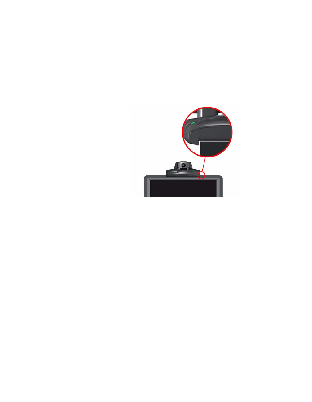
1. Place the ViewStation unit on top of the television monitor as
shown in Figure 1-1. Ensure that the front lip of the ViewStation
unit hangs over the edge of the television monitor.
Note Verify that the top surface area on the monitor is adequate
to support the ViewStation. The surface area of the
television monitor should provide enough support to prevent
the ViewStation from sliding off the monitor.
Figure 1-1. Placing the ViewStation
2. Connect the required cables to the back of the ViewStation as
shown in the ViewStation QuickStart card.
3. Center the microphone pod on a flat surface between the
meeting participants and the ViewStation.
4. Connect optional equipment, such as an additional television
monitor, a Video Cassette Recorder (VCR), a laptop, or a
document camera to the back of the ViewStation.
Secure all loose cables with the provided cable tie. This prevents
cables from getting tangled.
1. Slide one end of the cable tie through the square plastic cable
holder.
2. Attach the square connector to the back of the television
monitor.
Connecting the ViewStation to the ISDN or DCP Network
This section describes how to connect the ViewStation with the
following options to an ISDN or DCP network:
ViewStation User Guide 4 www.polycom.com
Page 21

Chapter 1 Getting Started
• ViewStation H.323 with Quad BRI
• ViewStation H.323 with Avaya DCP
• ViewStation 128
Before setting up the ViewStation to an ISDN network, ensure all
network connectivity iss ues are tes ted and reso lved.
ViewStation H.323 with Quad BRI
The ViewStation H.323 with Quad BRI uses up to four ISDN lines for
network connectivity and requires a Polycom Quad BRI inverse
multiplexer. The Quad BRI provides connectivity at a maximum
H.320 data rate of 512 Kbps. Complete the following steps to
connect the ViewStation H.323 with Quad BRI to the network:
1. Connect four ISDN lines from RJ-45 wall jacks on the ISDN
network to the connectors labeled ISDN S/T on the Quad BRI
network interface module.
2. Connect the green-tipped RJ-45 cable to the green RJ-45 port
on the back of the ViewStation as shown on the QuickStart card.
3. Connect the opposite end of the green-tipped RJ-45 cable into
the green RJ-45 port labeled
network interface module.
xon the Quad BRI
NT-1. If you are connected to an internal phone system, commonly
called a PBX, you need to connect the ISDN cables from the Quad
BRI network interface module to an ISDN network termination
(NT-1) device, which is connected to the ISDN wall jack.
For more ISDN information, refer to the Appendix D, ISDN
Information," on page 203.
Once the interface is properly connected, the ViewStation H.323
with Quad BRI is ready to be configured for Ethernet LAN
connectivity.
ViewStation H.323 with Avaya DCP
The ViewStation H.323 with Avaya DCP uses up to four DCP lines
for network connectivity and requires an Avaya DCP inverse
multiplexer. The Avaya DCP inverse multiplexer provides
connectivity to conduct videoconferences at a maximum H.320 data
© Polycom, Inc. 5 ViewStation User Guide
Page 22

Chapter 1 Getting Started
rate of 512 Kbps. Complete the following steps to connect the
ViewStation H.323 wit h Avaya DCP to the network:
1. Connect up to four DCP lines from RJ-45 wall jacks on the DCP
network to the connectors labeled ISDN S/T on the DCP
network interface module.
2. Locate the DCP cable shipped with the DCP network interface
module. This cable is identified with one transparent-tipped
keyed RJ-45 connector and a black-tipped non-keyed RJ-45
connector. Connect the RJ-45 cable with the black tip to the
green RJ-45 port on the back of the ViewStation as shown on
the QuickStart card.
3. Connect the opposite end of the keyed, white-tipped RJ-45
cable into the green RJ-45 port labeled
xon the DCP
network interface module.
Once the interface is properly connected, the ViewStation H.323
with Avaya DCP is ready to be configured for Ethernet LAN
connectivity. See Connecting the ViewStation to an Ethernet LAN,"
on page 8.
Note The ViewStation MP uses the Polycom Quad BRI network
interface module or the Avaya DCP network interface
module and up to four ISDN or DCP lines for network
connectivity. Use the Quad BRI or Avaya DCP network
configurations to connect your ViewStation MP to the
network.
ViewStation 128
The ViewStation 128 uses a single ISDN line and requires no
additional hardware (e.g., network interface module) for ISDN
connectivity at a maximum H.320 data rate of 128 Kbps. Complete
the following steps to connect the ViewStation 128 to an ISDN
network:
1. Connect the green-tipped RJ-45 cable to the green RJ-45 port
on the back of the ViewStation 128.
2. Connect the opposite end of the green-tipped cable to an ISDN
wall jack.
For more ISDN information, refer to “Appendix D, ISDN Information,"
on page 203.
ViewStation User Guide 6 www.polycom.com
Page 23

Chapter 1 Getting Started
Once the interface is properly connected, the ViewStation 128 is
ready to be configured for Ethernet LAN connectivity. See
“Connecting the ViewStation to an Ethernet LAN," on page 8.
Connecting the ViewStation H.323 with V.35 to a Network
The ViewStation H.323 with V.35 uses a Polycom V.35 network
interface module and has two HD-25 female ports (labeled 1 and 2)
that are used to connect to your Data Communications Equipment
(DCE).
Note Cable diagrams and pinout schematics are located in V.35
Technical Information," on page 193.
Connecting the V.35 Network Interface Module to the ViewStation
Complete the following steps to connect the V.35 network interface
module to the ViewStation:
1. Connect the green-tipped RJ-45 cable to the green RJ-45 port
on the back of the ViewStation.
2. Insert the opposite end of the green-tipped RJ-45 cable to the
port labeled
xon the network interface module.
Connecting the V.35 Network Interface Module to the V.35 DCE
Complete the following steps to connect the V.35 network interface
module to the V.35 DCE:
1. Connect the male HD-25 cable ends to ports 1 and 2 on the
network interface module. If you want to connect only one cable,
connect to port 1 on the interface module.
Connector screws should be lightly snug, not tight.
2. Connect the remaining cable ends to the DCE V.35/RS-449 port
and the DB-25/RS-366 dialing port, if used. If connecting one
cable only, connect to the lowest ordered port on the DCE.
© Polycom, Inc. 7 ViewStation User Guide
Page 24

Chapter 1 Getting Started
LED Activity on the V.35 Network Interface Module
The LEDs on the front of the V.35 network interface module indicate
the connection status to the ViewStation.
When the ViewStation is powered on, the following light sequence
occurs:
1. Both LEDs flash once to indicate that the LED is working
properly.
2. The bottom amber LED glows solid to indicate that the
ViewStation is communicating with the network interface
module.
3. The top green LED glows solid to indicate that the ViewStation
is communicating with the network.
The top green LED corresponds to port status, and the bottom
amber LED corresponds to DCE clock status.
Once the interface is properly connected, the ViewStation H.323
with V.35 is ready to be configured for Ethernet LAN connectivity.
Connecting the ViewStation to an Ethernet LAN
All ViewStation models use the same configuration type for
connecting the ViewStation to an Ethernet LAN. Complete the
following steps to connect the ViewStation to an Ethernet LAN:
1. Connect the orange-tipped RJ-45 cable to the orange RJ-45
port labeled LAN on the back of the ViewStation H.323.
2. Connect the opposite end of the orange-tipped RJ-45 cable to
an Ethernet LAN wall jack.
3. A green light appears on the orange RJ-45 port on the back of
the ViewStation if the LAN wall jack is active.
ViewStation User Guide 8 www.polycom.com
Page 25
Chapter 1 Getting Started
Initial System Configuration
This section explains how to set up the ViewStation. Except where
noted, the following section app lies to all ViewS tati on mod els .
Setup Common to all ViewStations
The following instructions is a set of general setup procedures which
cover all ViewStation models. Specific information that is unique to
each ViewStation model is noted.
1. Power on the television monitor and ViewStation.
2. On the Welcome screen (shown in Figure 1-2) select the
language used to display screens and information on the
ViewStation.
Figure 1-2. ViewStation Select Language Screen
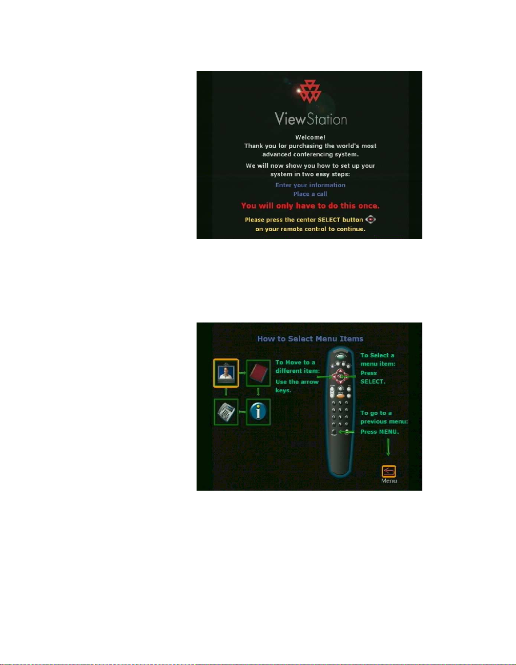
3. There are two ViewStation Welcome screens. The first is the
ViewSt a t ion Selec t Langua ge screen (shown in Figure 1-2)
Specify the desired country and language on this screen, and
press the SELECT button on the remote control to continue.
The main Welcome screen (shown in Figure 1-3) is a general
greeting in the language previously selected.
© Polycom, Inc. 9 ViewStation User Guide
Page 26
Chapter 1 Getting Started
Figure 1-3. ViewStation Main Welcome Screen
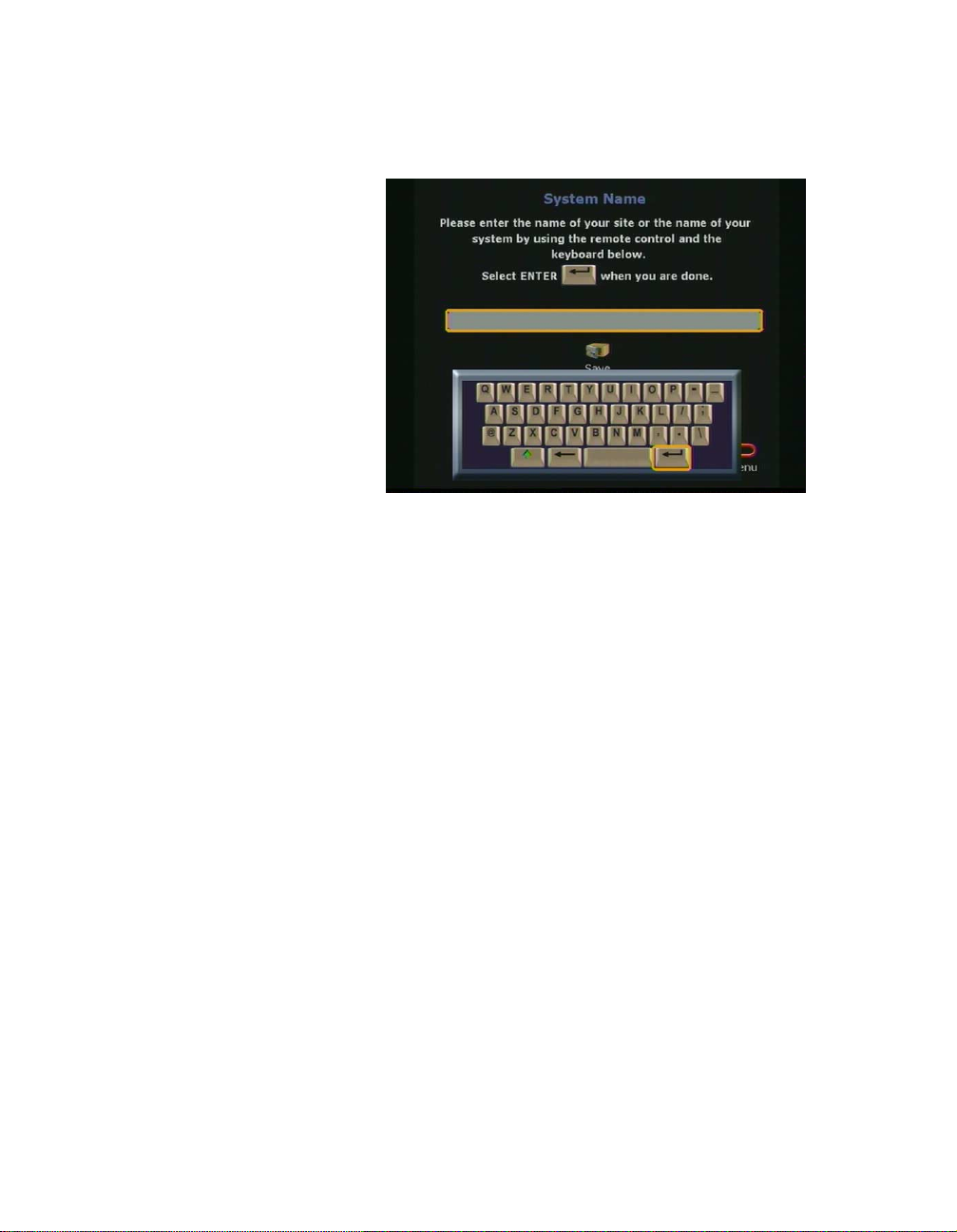
4. The next screen is the How to Select Menu Items screen
shown in Figure 1-4. Take a moment to familiarize yourself with
this screen. Press the SELECT button on the remote control to
continue.
Figure 1-4. How to Select Menu Items Screen
5. The System Name screen is where you assign a unique name
to the ViewStation.
Highlight the gray text field (shown in Figure 1-5) and press the
SELECT button on the remote control. You may enter up to 34
alphanumeric characters.
ViewStation User Guide 10 www.polycom.com
Page 27
Chapter 1 Getting Started
Highlight the Return icon and press the SELECT button on the
remote control. Select the Save icon to continue.
Figure 1-5. ViewStation System Nam e Screen
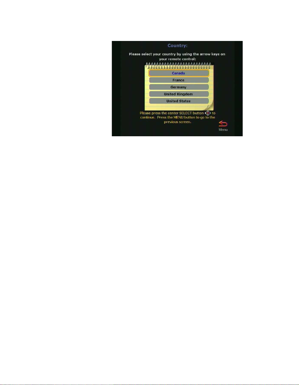
6. Select the country where the ViewStation is located. This setting
automatically configures ViewStation communications settings.
Use the ARROW buttons to scroll through the list. Using the
remote control, press the number that corresponds with the
country name. For example, country names beginning with T , U,
or V , press 8. The ViewSt ation menu goes to the first instance of
the countries beginning with the letter T. Highlight the desired
country, and press the SELECT button on the remote control.
© Polycom, Inc. 11 ViewStation User Guide
Page 28
Chapter 1 Getting Started
Figure 1-6. Select Country Screen
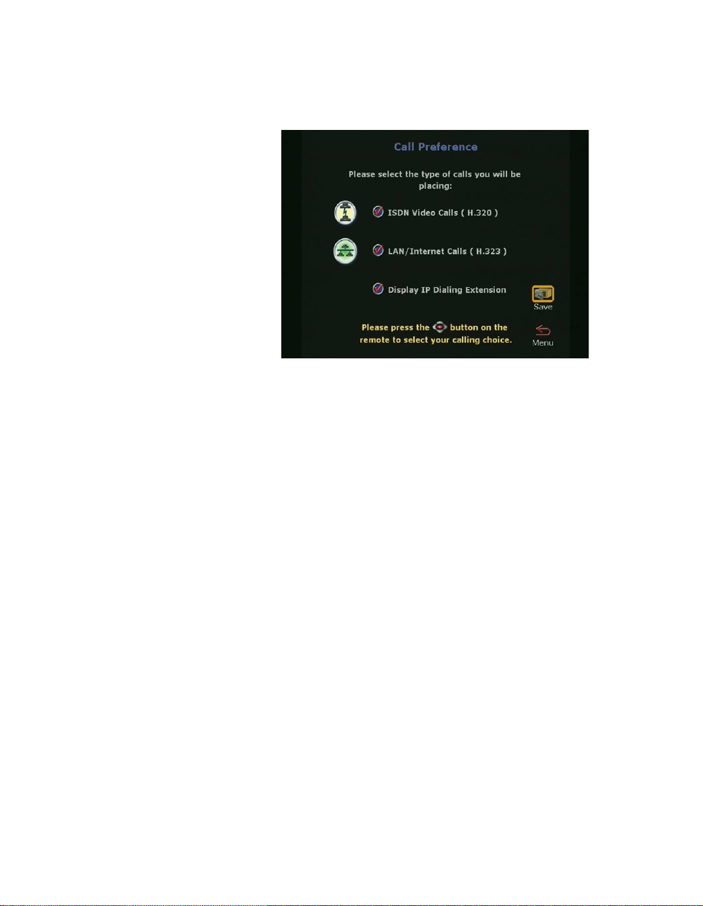
7. The Call Preference screen (Figures 1-7, 1-8, and 1-9) are
used to specify the type of calling preference.
ViewStation H.323 with Quad BRI and ViewStation 128.
ISDN Video Calls (H.320):
• Checked: Enables H.320 videoconferencing for the
ViewStation.
• Not Checked: Disables H.320 videoconferencing for
the ViewStation.
LAN/Internet Calls (H.323)
• Checked: Enables H.323 videoconferencing for the
ViewStation.
• Not Checked: Disables the H.323 videoconferencing
for the ViewStation.
Note At least one calling preference must be selected.
Display IP Dialing Extension: The IP Dialing Extension is used
if a ViewStation uses the Global Address Book (GAB). For more
information see Global Address," on page 75.
• Checked: The IP or E.164 Dialing Extension is
displayed when an H.323 video call is initiated.
ViewStation User Guide 12 www.polycom.com
Page 29
Chapter 1 Getting Started
• Not Checked: The IP or E.164 Dialing Extension is not
displayed when an H.323 video call is initiated.
Figure 1-7. Call Preference Screen For ISDN
8. For all ViewStation H.323 with Avaya DCP.
DCP Video Calls (H.320):
• Checked: Enables H.320 videoconferencing for the
ViewStation.
• Not Checked: Disables H.320 videoconferencing for
the ViewStation.
LAN/Internet Calls (H.323):
• Checked: Enables H.323 videoconferencing for the
ViewStation.
• Not Checked: Disables the H.323
videoconferencing for the ViewStation.
© Polycom, Inc. 13 ViewStation User Guide
Page 30

Chapter 1 Getting Started
Figure 1-8. DCP Call Preference Screen
Note At least one calling preference must be selected.
Display IP Dialing Extension: The IP Dialing Extension is used
if a ViewStation uses the Global Address Book (GAB.) For more
information see Global Address," on page 75.
• Checked: The IP or E.164 Dialing Extension is
displayed when an H.323 video call is initiated.
• Not Checked: The IP or E.164 Dialing Extension is not
displayed when an H.323 video call is initiated.
For ViewStation H.323 with V.35:
V.35 Video Calls:
• Checked: Enables V.35 videoconferencing for the
ViewStation.
• Not Checked: Disables V .35 videoconferencing for the
ViewStation.
LAN/Internet Calls (H.323)
• Checked: Enables H.323 videoconferencing for the
ViewStation.
• Not Checked: Disables the H.323 videoconferencing
for the ViewStation.
ViewStation User Guide 14 www.polycom.com
Page 31

Chapter 1 Getting Started
Note One calling preference must be selected.
Display IP Dialing Extension: The IP Dialing Extension is used
if a ViewStation uses the Global Address Book (GAB.) For more
information see Global Address," on page 75.
• Checked: The IP or E.164 Dialing Extension is
displayed when an H.323 video call is initiated.
• Not Checked: The IP or E.164 Dialing Extension is not
displayed when an H.323 video call is initiated.
Figure 1-9. V.35 Call Preference Screen
9. The H.323 Setup screen (shown in Figure 1-10) is used to
specify the H.323 name and extension. This screen appears
only when H.323 is enabled.
© Polycom, Inc. 15 ViewStation User Guide
Page 32

Chapter 1 Getting Started
Figure 1-10. H.323 Setup Screen
An Auto H.323 Dialing check box appears below the H.323
extension (E.164) when two or more dialing protocols are
enabled. Complete the following steps to enter information on
the H.323 Setup screen.
1. Enter a name in the H.323 name when calling this
system text box. Select a name which is easy to
remember, such as the name of a conference room.
2. Enter the H.323 extension (E.164). E.164 is a naming
scheme based on the ViewStation’s serial number and
MUST be unique to each ViewStation system.
3. Uncheck the Auto H.323 Dialing check box if displayed.
10. The Gatekeeper screen (shown in Figure 1-11) provides
terminal gateway registration, address resolutions, bandwidth,
and admission control. It is commonly used for point-to-point
Internet video calls.
A gatekeeper is not required for point-to-point Intranet video
calls. Select one of the following options for Gatekeeper:
•Off : Gatekeeper is not used.
• Specify: Enter the Gatekeeper IP address.
•Auto: The ViewStation automatically searches for a
Gatekeeper on the LAN. If no Gatekeeper is used, the
ViewStation continues to search for a gatekeeper until this
ViewStation User Guide 16 www.polycom.com
Page 33

Chapter 1 Getting Started
setting is changed. If the LAN has more than one
gatekeeper, specify the correct gatekeeper manually.
Figure 1-11. ViewStation H.323 Gatekeeper Screen
The following configuration screens are for specific ViewStation
models:
• For ViewStation H.323 with V.35, continue to step 11.
• For ViewStation 128, skip to step 12.
• For ViewStation H.323 with Quad BRI, skip to step 12.
• For ViewStation MP with Quad BRI, skip to step 12.
• For ViewStation H.323 with Avaya DCP, skip to step 13.
• For ViewStation MP with Avaya DCP, skip to step 13.
• For Vi ewStation H.323, skip to Step 17.
11. The Video Network screen (shown in Figure 1-12) is displayed
for ViewStations with a V.35 network interface module.
RS-366 Dialing:
• Checked: Enable the RS-366 dialing option if a call is made
from the ViewStation through the DCE connection to the far
site video communi ca tio ns sy s t em.
• Not checked: Disable RS-366 dialing option if:
• The DCE is used to dial the video call.
• A dedicated connection is used to connect the
ViewStation to the far site.
© Polycom, Inc. 17 ViewStation User Guide
Page 34

Chapter 1 Getting Started
V.35 Ports Used:
•1: For 1-channel calls when dialing through the V.35, or
when the ViewStation is in non-dialed mode.
•1-2: For 2 X 56 Kbps or 2 X 64 Kbps calls when dialing
through the V.35.
Figure 1-12. V.35 Video Network Screen
Dialing Protocol: RS-366 is displayed as the dialing protocol if
the RS-366 Dialing option is enabled. This field cannot be
changed.
Broadcast Mode: The ViewStation V.35 supports H.331
broadcast mode for broadcast transmissions over satellite. In
H.331 broadcast mode, the ViewStation sends and receives
audio and video without handshaking with either the far site
ViewStation or H.331-compatible video communications
systems. One ViewStation can send video and audio to many
ViewStations or other H.331-compatible systems, as in a large
satellite network.
• Checked: Enables broadcast mode. When checked, the
Broadcast Mode Setup icon appears.
• Not checked: Disables broadcast mode. When not
checked the Broadcast Mode Setup icon is not present.
ViewStation User Guide 18 www.polycom.com
Page 35

Chapter 1 Getting Started
Figure 1-13. Broadcast Mode Screen
Broadcast Mode: The Broadcast Mode screen (shown in
Figure 1-13) is used to configure the V.35 broadcast mode
properties:
• Video Format:
QCIF: T o transmit QCIF (Quarter Common Interchange
Format) 176 X 144 resolution, select QCIF.
FCIF: To transmit FCIF (Full Common Interchange
Format) 352 X 288 resolution, select FCIF.
• Video Protocol:
H.261: To transmit video using the H.261 standard,
select H.261.
H.263: To transmit video using the H.263 enhanced
video algorithm, select H.263. If the far-site systems
support H.263, your system receives H.263. If the far
site systems support H.261, your ViewStation adjusts to
support H.261 video.
• Audio Mode: The audio mode can be adjusted to
compensate for distorted audio due to high packet loss.
Select the preferred audio protocol for transmitting audio:
G.728 (Default)
G.711u
G.711A
G.722-56
© Polycom, Inc. 19 ViewStation User Guide
Page 36

Chapter 1 Getting Started
G.722-48
Off
• Frame Rate: The frame rate is the number of frames per
second (fps) transmitted by the ViewStation to the far site.
This is adjustable to compensate for distorted video due to
high packet loss. Select the preferred video frame rate for
the broadcast transmission in frames per second or fps:
– 30 fps (Default)
– 15 fps
– 10 fps
– 7.5 fps
Set broadcast configuration parameters to accommodate the
lowest common denominator of the video communication
systems that receive the video and audio broadcasts. For
example, if one video communication system participating in
the video supports H.261 only, set the video protocol to
H.261 to ensure that all systems are able to participate.
Figure 1-14. Advanced Dialing Screen
If RS-366 Dialing is enabled on the Video Network screen, the
Advanced V.35 scr een is disp lay ed .
• Prefix/Suffix: Use the Advanced V.35 screen (shown if
Figure 1-14) to set the dialing prefixes and suffixes. Dialing
prefixes are numbers and characters that are sent to the
DCE equipment before the dialed number is sent. Dialing
ViewStation User Guide 20 www.polycom.com
Page 37

Chapter 1 Getting Started
suffixes are numbers and characters that are sent to the
DCE equipment after the dialed number is sent.
Use prefixes and suffixes to set the DCE speed used to dial
a call.
Note Prefixes and suffixes are a function of the DCE. See your
DCE User Documentation for information about setting
dialing profiles to the DCE specific equipment.
• Calling Profiles: Calling profiles are configured on the
Advanced V.35 screen. To select and change the profiles,
highlight the Calling Profile field and select the specific
equipment.
• Dialing Speeds: If RS-366 dialing is enabled on the Video
Network screen, the Dialing Speeds screen is displayed.
Figure 1-15. Dialing Speeds Screen
On this screen, specify the dialing speeds available to users when
placing video calls. The default speeds are:
– 2 X 64 Kbps
– 256 Kbps
– 384 Kbps
– 512 Kbps
• To add or remove speeds, scroll though the data rates and
press the SELECT button on the remote control to choose
© Polycom, Inc. 21 ViewStation User Guide
Page 38
Chapter 1 Getting Started
the preferred dialing speeds. A red check is displayed when
a dialing speed is selected.
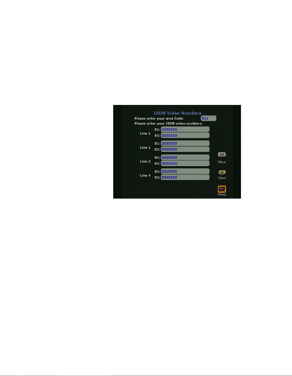
12. On the ISDN Video Numbers screen (shown in Figure 1-16),
complete the following:
• Enter your local area or STD code.
• Enter the ISDN numbers assigned to your ViewSt ation. The
ISDN service provider should have provided this number
when your ISDN line was installed.
Figure 1-16. ISDN Video Numbers Screen
13. DCP Video Numbers
• On the DCP Video Numbers screen (shown in Figure
1-17), enter the area or STD code.
• Enter the vid e o nu m be rs assigned to th e ViewStation DC P.
If the video numbers are not known, contact a Definity
administrator.
ViewStation User Guide 22 www.polycom.com
Page 39

Chapter 1 Getting Started
Figure 1-17. DCP Video Numbers Screen
14. Auto Detect SPIDs:
• On the Auto Detect SPIDs screen (shown in Figure 1-18),
enter the Service Profile ID (SPIDs) numbers for the
ViewStation. If connected to an internal phone system
(PBX) or if t he ViewS tat ion is out side North Am erica, a SPID
may not be required.
OR
• Select the START icon for the ViewStation to automatically
detect SPIDs.
Note If the ViewStation is unable to find the SPIDs, check the
network connection and verify that the ISDN have been
entered correctly.
© Polycom, Inc. 23 ViewStation User Guide
Page 40

Chapter 1 Getting Started
Figure 1-18. Auto Detect SPIDs Screen
To manually enter the SPID numbers for the ViewStation as shown
in Figure 1-18, highlight each line and channel, and press the
SELECT button on the remote control. Enter the SPID numbers
accordingly.
15. If PBX is selected on the Auto Detect SPIDs screen, the
following screen (shown in Figure 1-19) requires the number
used to obtain an outside line.
Figure 1-19. Outside Line Calls Screen
ViewStation User Guide 24 www.polycom.com
Page 41

Chapter 1 Getting Started
16. ISDN Switch Protocol:
Select the ISDN switch protocol according to the ISDN switch
type used with the ISDN network, as shown in Figure 1-20.
Figure 1-20. ISDN Switch Protocol Screen
17. The T e lephone Numbers screen shown in Figure 1-21 is where
the telephone number for the ViewStation (if used) is entered.
An additional field is provided for the telephone where the
ViewStation is used.
Figure 1-21. Telephone Numbers Screen
When the Main Calling screen is displayed as shown in Figure 1-22,
the ViewStation setup is complete.
© Polycom, Inc. 25 ViewStation User Guide
Page 42

Chapter 1 Getting Started
Figure 1-22. Main Calling Screen
At the top left of the Main Calling screen is the ViewStation type
indicator, which is displayed below the Polycom logo. This indicates
the network interface module (if any) that is configured with the
ViewStation.
Network Status Indicators
Each time the ViewStation is powered on, a set of network status
indicators (network icons) are displayed below the Video Call icon
on the Main Calling screen. The Network icon flashes a yellow
numbered box while the ViewStation is validating each network line
or is waiting for the DHCP server (if used) to assign it an IP address.
If the ViewStation uses a static or fixed IP address, the ViewStation
verifies the IP is not in use.
Icon Meaning
Network line is connected.
The ViewStation is ready to place a video call.
Green Up Arrow
ViewStation User Guide 26 www.polycom.com
Page 43

Chapter 1 Getting Started
The ViewStation is checking the status of the
network line.
Yellow Box
Network line failed to validate:
This may be because the network cable is not
connected to the network, or is not functioning
properly. Check the cable connection, contact
Red Down Arrow
your Network Manager or see Network and
Communications," on page 182.
© Polycom, Inc. 27 ViewStation User Guide
Page 44
Chapter 1 Getting Started
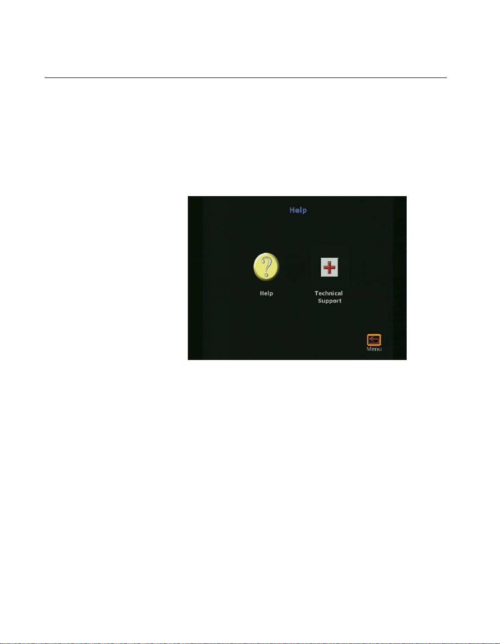
Using the ViewStation Help
To access the ViewStation Help screen, press the INFO button on
the remote control. If your organization is not using the Polycom
Global Management System, pressing the INFO button on the
remote control takes you directly to the Help screen. If your
organization is using the Polycom Global Management System, two
icons appear on the screen. The first icon is the Help screen (noted
below). The second icon is the Global Management System
Technical Support icon and appears only when GMS is used.
Figure 1-23. Help Screen
Using ViewStation Help
To access the Help screen, highlight the INFO button and press the
SELECT button on the remote control.
The Help screen is used to obtain information about:
• Navigation with the remote control
• Placing a video call
• Connecting to a PC
• Using PowerPoint to display slides
• Making camera selections
• Using voice tracking
• Setting camera presets
ViewStation User Guide 28 www.polycom.com
Page 45

Chapter 1 Getting Started
• Sending telephone touch tones.
Figure 1-24. Help Screen
To choose a topic on t he Help screen, highlight the desired icon and
press the SELECT button on the remote control.
Technical Support
The Technical Support icon (shown in Figure 1-23) is visible only
when the ViewStation is using the Polycom Global Management
System
Global Management System
84.
™. For more information on how to setup the Polycom
, see Global Management," on page
© Polycom, Inc. 29 ViewStation User Guide
Page 46

Chapter 1 Getting Started
Figure 1-25. Technical Support Help Screen
To obtain Technical Support from the Polycom Global Management
System, highlight the Technical Support icon and press the
SELECT button on the remote control. A dialog box appears (Figure
1-25) asking you to enter a phone number. In order to provide rapid
assistance, please include the area code with your phone number.
Once your phone number has been entered, a confirmation screen
appears. This screen also displays a phone number you can use to
contact technical support by voice directly.
ViewStation User Guide 30 www.polycom.com
Page 47

Optional Configurations
This chapter contains user and administrative setup information.
Except where noted, this applies to all ViewStation models.
User Setup
The User Setup screen (System Info > User Setup) serves as a
quick configuration tool allowing the ViewStation administrator or
LAN manager to set basic options for the ViewStation as shown in
Figure 2-1.
2
Figure 2-1. User Setup Screen
Auto Answer: The Auto Answer option allows the ViewStation
to automatically answer incoming video calls.
• Checked: The ViewStation automatically answers incoming
video calls.
• Not Checked: Incoming calls ring until the call is manually
answered or the far site disconnects.
Mute Auto Answer Calls: This option turns the microphone pod
off and prevents the far site from hearing the near site when the
ViewStation automatically answers incoming video calls.
© Polycom, Inc. 31 ViewStation User Guide
Page 48

Chapter 2 Optional Configuration s
• Checked: The ViewStation mutes near site audio for
incoming video calls when the ViewStation automatically
answers incoming video calls.
• Not Checked: The ViewStation sends audio to the far site
as normal.
When the ViewStation is muted, both sites are notified with
a microphone image located in the lower left side of the
main screen. A red light illuminates on the microphone pod
when the near site is muted.
PiP or Picture-in-Picture: The PiP feature allows the near site to
adjust near camera views while in a videoconference. In this
configuration, the Camera icon in the top right corner disappears
when the remote control is placed on a flat surface.
•Auto: The ViewStation shows a PiP window when the call is
first connected and when the remote control is not resting on
a flat surface.
•On: The ViewStation shows a PiP window that remains in
the lower right corner until the video call is completed.
•Off: The ViewStation does not show a PiP window.
Far Control of Near Camera: The Far Control of Near Camera
option allows users at the far site to control the camera at the near
site.
• Checked: A user on the far site may control the framing or
angle of the camera on the near site by pressing the FAR
button on the remote control.
• Not Checked: A user cannot change the framing and angle
of the camera. When a far site user presses the FAR or
ZOOM button on the remote control, any attempts to change
the current orientation of the camera are ignored.
Backlight Compensation: The backlight compensation is used
in conference rooms where the subject appears darker than the
background. Use backlight compensation if the meeting
participants appear to be in shadow.
• Checked: The camera automatically adjusts for a light
background.
• Not Checked: Uncheck the backlight compensation if
moderate lighting is used for the ViewStation.
ViewStation User Guide 32 www.polycom.com
Page 49

Chapter 2 Optional Configuration s
Allow Remote Monitoring: Remote monitoring allows a user to
remotely view a conference room prior to a scheduled meeting
using the ViewStation Web interface. See "Using th e ViewSt ation
with a PC" on page 133.
• Checked: The ViewStation sends images every 10 seconds
to the ViewStation Web page.
• Not Checked: The ViewStation does not send any images.
Meeting Password: The meeting password is used to grant or
restrict access to the non-administrative functions of the
ViewStation’s Web interface. See "Using the ViewStation Web
Interface" on page 139.
• Text field empty: No password is required.
• Text field populated: When the Meeting Password text
field is populated with a password, that password is used to
grant or restrict access the non-administrative features of
the ViewStation web interface.
Far site name display time: The far site name display time
displays the name of the far site for a defined number of seconds.
• 15 seconds: (Default) The far site name is displayed for 15
seconds.
•Blank: The far site name is displayed until the call is ended.
MP Mode: (MP-enabled ViewStations only.) The MP mode sets
the viewing mode for multi-point video calls into one of the
following options:
•Auto: The ViewStation automatically switches between
discussion and presentation modes.
• Discussion: This mode is also called the continuous
presence. Each site remains on the screen in a tiled
arrangement.
• Presentation: The main presenter remains on the screen.
• Full Screen: Whoever is speaking is viewed in full screen.
When a new endpoint speaks, that endpoint appears full
screen.
© Polycom, Inc. 33 ViewStation User Guide
Page 50

Chapter 2 Optional Configuration s
Admin Setup
The Admin Setup screen (System Info > Admin Setup) is used to
access the advanced configuration features of the ViewStation.
Figure 2-2. Admin Setup Screen
The following table lists which icons are available for each
ViewStation model:
Icon Name ViewStation Model Location
General Setup All System Info > Admin Setup >
General Setup
Video Network BRI, DCP, V.35, 128 System Info > Admin Setup >
Video Network
LAN / H.323 All System Info > Admin Setup >
LAN / H.323
Data Conference All System Info > Admin Setup >
Data Conference
Phone / Audio All System Info > Admin Setup >
Phone / Audio
Video / Camera All System Info > Admin Setup >
Video / Camera
ViewStation User Guide 34 www.polycom.com
Page 51

Chapter 2 Optional Configuration s
Icon Name ViewStation Model Location
Security All System Info > Admin Setup >
Security
Software / Hardware All System Info > Admin Setup >
Software / Hardware
General Setup
The General Setup screen (System Info > Admin Setup >
General Setup) is used to access the advanced configuration
features of the ViewStation not contained in the User Setup screen.
The General Setup screen (shown in Figure 2-3) has the following
seven user-configurable fields:
• Country: Sets the country where the ViewStation is
used
• Language: Sets one of the languages used for the
ViewStation
• System Name: Sets the name displayed in a call for the
ViewStation
• Auto Answer: Sets the auto-answer feature when the
ViewStation receives an incoming call
• Allow Dialing: Permits or denies the ability to place a
video call from the ViewStation
• Allow User Setup: Permits or denies access to the
User Setup screen
• Maximum Time in a Call: Sets the maximum time for a
video call
© Polycom, Inc. 35 ViewStation User Guide
Page 52

Chapter 2 Optional Configuration s
Figure 2-3. General Setup Screen
Country: The Country field of th e General Setup screen ( shown
in Figure 2-3) allows you to specify country specific calling
parameters for your location. Click the Country field to access
the Country Setup screen (Figure 2-4).
Figure 2-4. Country Setup Screen
The fields in the Country Setup screen allow you to set loc al
calling parameters:
• Country: To select a count ry, highlight the blue coun try
text field and press the SELECT button on the remote
control. Scroll down the list of countries and highlight
ViewStation User Guide 36 www.polycom.com
Page 53

Chapter 2 Optional Configuration s
the desired country. The country code appears with the
corresponding country.
• Area Code Required:
• Checked: The ViewStation automatically
adds the area code to the ISDN or DCP
dialing prefix of calls placed from the
ViewStation.
• Not Checked: The ViewStation dials all calls
as if the calls were placed within the local area
code.
• Phone International Access: The international prefix
is 011 for North America and 00 for European countries.
The default depends on the country. Highlight the blue
text field on the Phone International Access field.
Enter the assigned prefix to make international calls.
When complete, highlight the Menu icon and press the
SELECT button on the remote control.
Language: The Language field selects the language used for
the ViewStation (see "Setup Common to all ViewStations" on
page 9.) Highlight the desired flag associated with a language
and press the SELECT button on the remote control.
System Name: The system name is the name assigned by the
user to identify the ViewStation. This can be any combi nat ion of
alphanumeric characters up to 34 characters in length.
Auto Answer: The Auto Answer option allows the ViewStation
to automatically answer incoming video calls.
• Checked: The ViewStation automatically answers incoming
video calls.
• Not Checked: Incoming calls ring until they are manually
answered or the far site disconnects the call.
Allow Dialing: The Allow Dialing option enables or disables
dialing and access to the address book on the ViewStation.
• Checked: The ViewStation allows dialing and access to the
address book.
• Not Checked: The ViewStation prevents dialing and denies
access to the address book.
© Polycom, Inc. 37 ViewStation User Guide
Page 54

Chapter 2 Optional Configuration s
Figure 2-5 shows the message that is displayed when the
Allow Dialing feature is not checked.
Figure 2-5. Allow Dialing Disabled Screen
Allow User Setup: The Allow User Setup option enables or
disables users from changing the User Setup by removing the
icon from the System Information screen as shown in Figure
2-6. This is generally used when the user setup policy has been
defined by the LAN manager or the ViewStation administrator.
• Checked: Allows chang es to the User Setup settings.
• Not Checked: Prevents changes to the User Setup
settings.
Figure 2-6. Allow User Setup Disabled on System Information Screen
ViewStation User Guide 38 www.polycom.com
Page 55

Chapter 2 Optional Configuration s
Maximum Time in Call: The default time for the maximum time
in a call is 480 minutes. When the maximum time in a call is met,
the ViewStation displays a yellow dialog box stating that the
length of the call has reached the set time and asks if you want to
continue the call. If the call is extended, the time of the extended
call is equal to the set maximum time in a call.
Video Network
The Video Network is used to configure ISDN, DCP, MP, and V.35
configurations for the ViewStation.
ViewStation H.323 with Quad BRI
The Network Setup screen ( System Info > Admin Setup > Video
Network) shown in Figure 2-7 provides four icons, which:
• Configure IMUX properties
• Configure ISDN Video Network properties
• Set Call Preferences
• Set Multi-Point Preferences (MP enabled systems only)
Figure 2-7. Video Network Screen (MP Enabled ViewStations Only)
IMUX (Inverse Multiplexer):
On the IMUX screen (System Info > Admin Setup > Video
Network > IMUX) the five icons as shown in Figure 2-8 are:
• Numbers: Sets ISDN video numbers
© Polycom, Inc. 39 ViewStation User Guide
Page 56

Chapter 2 Optional Configuration s
•SPIDs: Sets the Service Profile IDs. SPID numbers are
assigned to every terminal device by the ISDN provider.
This is generally used in North America only
• Audio Quality: Adjusts the audio quality of a video call
• Advanced Dialing: Defines how a channel is dialed
• Dialing Speeds: Defines dialing speed available when a
call is placed
Figure 2-8. Inverse Multiplexer Information Screen
Numbers
The Numbers screen (System Info > Admi n Setup > Video
Network > IMUX > Numbers) allows the ViewStation administrator
or the LAN manager to enter the STD or area code and the ISDN
Video numbers for each ISDN line.
ViewStation User Guide 40 www.polycom.com
Page 57

Chapter 2 Optional Configuration s
Figure 2-9. ISDN Video Numbers Screen
1. Enter the STD or area code and press the down arrow on
the remote control to continue to the next line.
2. Enter the ISDN phone number used for each line.
3. When complete, highlight the Save icon and pres s the
SELECT button on the remote control.
Service Profile Identifier
The Service Profi le Identifier screen (System Inf o > Admin Setu p
> Video Network > IMUX > SPIDS) or SPIDs appears only if United
States or Canada is selected as the country. If the ViewStation is
connected to an internal phone system (PBX), a SPID may not need
to be entered.
Note If the ViewStation is unable to find the SPIDs, check the
network connection and verify that the ISDN numbers have
been entered correctly.
• Enter the SPID numbers provided by the ISDN service
provider.
• If the ViewStation is connected to a PBX, select the PBX
icon. In some case s you may n ot nee d to loc ate SPI Ds.
• To auto-detect SPID numbers, highlight the Start icon
and press the SELECT button on the remote control.
© Polycom, Inc. 41 ViewStation User Guide
Page 58

Chapter 2 Optional Configuration s
Note If this process is canceled, the ViewStation reboots and the
entire setup procedure must be redone
Figure 2-10. Auto Detect SPIDs Screen
.
Audio Quality
The Audio Quality Pref er ence screen (System Info > Admin
Setup > Video Network > IMUX > Audio Quality) allows the
selection of an audio protocol. G.722 audio delivers a higher quality
of audio than G.728 and uses 48 Kbps of the call bandwidth. G.728
delivers telephone quality audio and only uses 16 Kbps of the call
bandwidth. G.728 is generally used for lower data rates.
To set the audio protocol, use the + and - zoom buttons on the
remote control to move the slider.
Note Changing the audio quality preferences during a call can be
done only while in an H.320 call. No changes can be made
while in an H.323 call.
ViewStation User Guide 42 www.polycom.com
Page 59

Chapter 2 Optional Configuration s
Figure 2-11. Audio Quality Screen
Advanced Dial ing
On the Advanced Dialing screen (System Info > Admin Setup >
Video Network > IMUX > Advanced Dialing) you can define how
each ISDN channel is dialed. By default, channels are dialed in
parallel.
• Dial channels in parallel: When this option is selected,
the ViewStation dials all ISDN channels simultaneously.
• Dial channels one at a time: When selected, the
ViewStation dials each ISDN channel one at a time until
all the channels are connected. This feature is used to
overcome local network problems.
© Polycom, Inc. 43 ViewStation User Guide
Page 60

Chapter 2 Optional Configuration s
Figure 2-12. Advanced Dialing Screen
Dialing Speeds
The Dialing Speeds screen (System Info > Admin Setup > Video
Network > IMUX > Dialing Speeds) spe ci fie s the diali ng spe eds
that are available when a call is placed.
Figure 2-13. Dialing Speeds Screen
Highlight the circle to the right of a speed and press the SELECT
button on the remote control to select that speed. A red check mark
appears on the Dialing Speeds screen when a speed is selected.
ViewStation User Guide 44 www.polycom.com
Page 61

Chapter 2 Optional Configuration s
ISDN Video Network
The ISDN Video Network screen (System Info > Admin Setup >
Video Network > ISDN Video Network) contains information
entered during system setup. The five user-configurable fields are:
Country Code: Choose the country code associated with the
country where the ViewStation is used.
Area Code: Choose the area code or STD code where the
ViewStation is used.
Number A: Enter the primary ISDN number assigned to the
ViewStation.
Number B: Enter the secondary ISDN number assigned to the
ViewStation.
ISDN Switch Protocol: Select the appropriate ISDN switch
protocols. Contact the ISDN provider to determine the ISDN
switch protocol.
ISDN Dialing Prefix: The ISDN dialing prefix is used to access
an outside line if the ViewStation is connected to a PBX.
Figure 2-14. ISDN Video Network
© Polycom, Inc. 45 ViewStation User Guide
Page 62

Chapter 2 Optional Configuration s
Call Preference
The Call Preference screen (System Info > Admin Setup > Video
Network > Call Preference) shown in Figur e 2- 15 de te rmin es how
a video call is made. The two types of calls made are:
• ISDN Video Calls (H.320)
• LAN/Internet Calls (H.323)
ISDN Video Calls (H.320):
• Checked: Enables ISDN videoconferencing on the
ViewStation.
• Not Checked: Disables ISDN videoconferencing ability on
the ViewStation
.
Figure 2-15. Call Preference Screen
LAN/Internet Calls (H.323):
• Checked: Enables H.323 videoconferencing on the
ViewStation.
• Not Checked: Disables H.323 videoconferencing on the
ViewStation.
• Display IP Dialing Extension: The IP dialing extension is
used if a ViewStation uses the Global Address Book (GAB).
Checked: The E.164 dialing extension is displayed when
a video call is initiated in H.323 calls.
ViewStation User Guide 46 www.polycom.com
Page 63

Chapter 2 Optional Configuration s
Not Checked: The E.164 dialing extension is not
displayed when a video call is initiated in H.323 calls.
Multi-Point Setup (MP Enabled ViewStations)
The Multi-Point setup screen determines which mode the
multi-point feature is used. The modes are:
•Auto: The ViewStation automatically switches between
discussion and presentation mode.
• Discussion: This mode is also called the continuous
presence. Each site remains on the screen in a tiled
arrangement.
• Presentation: The main presenter remains on the screen
while each end point switches on and off.
• Full Screen: Whoever is speaking is viewed in full screen.
When a new endpoint speaks, that endpoint appears full
screen.
ViewStation H.323 with Avaya DCP
The Network Setup screen (System Info > Admin Setup > Video
Network) shown in Figure 2-16 provides four icons which:
• Configure IMUX properties
• Configure DCP Video Network properties
• Set Call Preferences
• Set Multi-Point Setup preferences (MP systems only).
Figure 2-16. Network Setup Screen (MP Enabled ViewStations Only)
© Polycom, Inc. 47 ViewStation User Guide
Page 64

Chapter 2 Optional Configuration s
IMUX (Inverse Multiplexer):
On the IMUX screen (System Info > Admin Setup > Video
Network > IMUX), the four icons as shown in Figure 2-17 are:
• Numbers: Sets DCP video numbers
• Audio Quality: Adjusts the audio quality of a video call
• Advanced Dialing: Defines how a channel is dialed
• Dialing Speeds: Defines dialing speed available when a
call is placed.
Figure 2-17. Inverse Multiplexer Information Screen
Numbers
The Numbers screen (System Info > Admi n Setup > Video
Network > IMUX > Numbers) allows the ViewStation administrator
or the LAN manager to enter the STD or area code and the DCP
video numbers for each DCP line.
ViewStation User Guide 48 www.polycom.com
Page 65
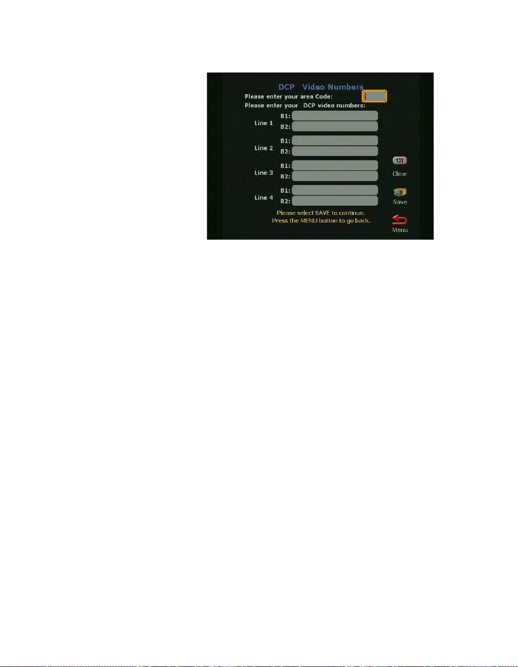
Chapter 2 Optional Configuration s
Figure 2-18. DCP Video Numbers Screen
1. Enter the STD or area code and press the down arrow on
the remote control to continue to the next line.
2. Enter the DCP phone number used for each line.
3. When complete, highlight the Save icon and pres s the
SELECT button on the remote control.
Audio Quality
The Audio Quality Pref er ence screen (System Info > Admin
Setup > Video Network > IMUX > Audio Quality) allows the
selection of an audio protocol. G.722 audio delivers a higher quality
of audio than G.728 and uses 48 Kbps of the call bandwidth. G.728
delivers telephone quality audio and only uses 16 Kbps of the call
bandwidth. G.728 is generally used for lower data rates.
To set the audio protocol, use the + and - zoom buttons on the
remote control to move the slider.
Note Changing the audio quality preferences in a call can only be
done in an H.320 call. No changes can be made while in an
H.323 call.
© Polycom, Inc. 49 ViewStation User Guide
Page 66

Chapter 2 Optional Configuration s
Figure 2-19. Audio Quality Screen
Advanced Dial ing
On the Advanced Dialing screen (System Info > Admin Setup >
Video Network > IMUX > Advanced Dialing) you can define how
each DCP channel is dialed. By default, channels are dialed in
parallel.
• Dial channels in parallel: When this option is selected,
the ViewStation dials all DCP channels simultaneously.
• Dial channels one at a time: When selected, the
ViewStation dials each DCP channel one at a time until
all the channels are connected. This feature is used to
overcome local network problems.
ViewStation User Guide 50 www.polycom.com
Page 67

Chapter 2 Optional Configuration s
Figure 2-20. Advanced Dialing Screen
Dialing Speeds
The Dialing Speeds screen (System Info > Admin Setup > Video
Network > IMUX > Dialing Speeds) spe ci fie s the diali ng spe eds
that are available when a call is placed.
Figure 2-21. Dialing Speeds Screen
• Highlight the circle to the right of a speed and press the
SELECT button to select that speed. A red check mark
appears on the Dialing screen when a speed is
selected.
© Polycom, Inc. 51 ViewStation User Guide
Page 68

Chapter 2 Optional Configuration s
DCP Video Network
The DCP Video Network screen (System Info > Admin Setup >
Video Network > DCP Video Network) contains information
entered during system setup. The five user-configurable fields are:
Country Code: Choose the Country Code associated with the
country where the ViewStation is used.
Area Code: Choose the Area Code or STD Code where the
ViewStation is used.
Number A: Enter the primary DCP number assigned to the
ViewStation.
Number B: Enter the secondary DCP number assigned to the
ViewStation.
DCP Switch Protocol: Select the appropriate DCP switch
protocols. Contact the DCP provider to determine the DCP switch
protocol.
DCP Dialing Prefix: The DCP dialing prefix is used to access an
outside line if the ViewStation is connected to a PBX.
Figure 2-22. DCP Video Network Screen
ViewStation User Guide 52 www.polycom.com
Page 69

Chapter 2 Optional Configuration s
Call Preference
The Call Preference screen (System Info > Admin Setup > Video
Network > Call Preference) shown in Figur e 2- 23 de te rmin es how
a video call is made. The two types of calls made are:
• DCP Video Calls (H.320)
• LAN/Internet Calls (H.323)
DCP Video Calls (H.320):
• Checked: Enables H.320 videoconferencing on the
ViewStation.
• Not Checked: Disables H.320 videoconferencing ability on
the ViewStation
.
Figure 2-23. Call Preference Screen
LAN/Internet Calls (H.323):
• Checked: Enables H.323 videoconferencing on the
ViewStation.
• Not Checked: Disables H.323 videoconferencing on the
ViewStation.
• Display IP Dialing Extension: The IP dialing extension is
used if a ViewStation uses the Global Address Book (GAB).
Checked: The E.164 Dialing Extension is displayed when
a video call is initiated in H.323 calls.
© Polycom, Inc. 53 ViewStation User Guide
Page 70

Chapter 2 Optional Configuration s
Not Checked: The E.164 Dialing Extension is not
displayed when a video call is initiated in H.323 calls.
Multi-Point Setup (MP Enabled ViewStations only)
The Multi-Point setup screen determines which mode the
multi-point is used in. These modes are:
•Auto: The ViewStation automatically switches between
discussion and presentation modes.
• Discussion: This mode is also called the continuous
presence. Each site remains on the screen in a tiled
arrangement.
• Presentation: The main presenter remains on the screen.
Full Screen: Whoever is speaking is viewed in full screen.
When a new endpoint speaks, that endpoint appears full
screen.
ViewStation 128
The Network Setup screen ( System Info > Admin Setup > Video
Network) shown in Figure 2-24 provides three icons, which:
• Set Dialing Speeds
• Configure Video Network properties
• Set Call Preferences
Figure 2-24. ViewStation 128 ISDN Network Setup Screen
ViewStation User Guide 54 www.polycom.com
Page 71

Chapter 2 Optional Configuration s
Dialing Speeds
The Dialing Speeds screen (System Info > Admin Setup > Video
Network > Dialing Speeds) specifies the dialing speeds that are
available when a call is placed.
Figure 2-25. Dialing Speeds Screen
Highlight the box to the right of a speed and press the SELECT
button to select that speed. A red check mark appears on the
Dialing screen when a speed is selected.
ISDN Video Network
The ISDN Video Network screen (System Info > Admin Setup >
Video Network > ISDN Video Network) contains information
entered during system setup. The six user configurable fields are:
Country Code: Choose the Country Code associated with the
country where the ViewStation is used
Area Code: Choose the Area Code or STD Code where the
ViewStation is used
Number A: Enter the primary ISDN number assigned to the
ViewStation
Number B: Enter the secondary ISDN number assigned to the
ViewStation
© Polycom, Inc. 55 ViewStation User Guide
Page 72

Chapter 2 Optional Configuration s
ISDN Switch Protocol: Select the appropriate ISDN switch
protocols. Contact the ISDN provider to determine the ISDN
switch protocol.
Service Profile IDs (SPIDs): The Service Profile Identifiers
screen (SPIDs) appears only if United States or Canada is
selected as the country. If the ViewStation is connected to an
internal phone system (PBX), a SPID might not need to be
entered.
Note If the ViewStation is unable to find the SPIDs, check the
network connection and verify that the ISDN numbers have
been entered correctly:
• Enter the SPID numbers provided by the ISDN service
provider.
• If the ViewStation is connected to a PBX, select the PBX
icon.
To auto-detect the SPID numbers, highlight the Start icon and
press the SELECT button on the remote control.
Note If this process is canceled, the ViewStation reboots and the
entire setup procedure must be redone.
ISDN Dialing Prefix: The ISDN dialing prefix is used to access an
outside line if the ViewStation is connected to a PBX.
ViewStation User Guide 56 www.polycom.com
Page 73

Chapter 2 Optional Configuration s
ViewStation H.323 with V.35
The Network Setup screen (System Info > Admin Setup > Video
Network) shown in Figure 2-26 provides four icons which:
• Sets Call Preferences
• Configures Video Network preferences
• Sets video Numbers
• Access the Advanced V.35 Setup features
Figure 2-26. V.35 Network Setup Screen
Call Preference
The Call Preference screen shown in Figure 2-27 determines how
a video call is placed. The two types of video communications for the
ViewStation H.323 with V.35 are:
• V.35 video calls
• LAN/Internet (H.323) video call s
V.35 Video Calls: The V.35 Video Calls option shown in the first
check box in Figure 2-28 determines if V.35 calls are made from
the ViewStation.
• Checked: Enables the V.35 videoconferencing for the
ViewStation H.323 with V.35.
• Not Checked: Disables the V .35 videoconferencing for the
ViewStation H.323 with V.35.
© Polycom, Inc. 57 ViewStation User Guide
Page 74

Chapter 2 Optional Configuration s
Figure 2-27. V.35 Call Preference Screen
LAN/Intranet Calls (H.323)
The LAN/Intranet Calls option shown in the second check box in
Figure 2-27 determines if H.323 calls are made from the
ViewStation.
• Checked: Enables H.323 videoconferencing for the
ViewStation.
• Not Checked: Disables H.323 videoconferencing for the
ViewStation.
Display IP Dialing Extension
• Checked: Displays the IP dialing extension used in H.323
video calls from and to the ViewStation.
• Not Checked: The IP dialing extension is not displayed for
H.323 video calls.
Video Network for V.35
The Video Network screen shown in Figure 2-28 is used to
configure the following prope rties :
• RS-366 Dialing
• V.35 Ports Used
• Dialing Protocol
ViewStation User Guide 58 www.polycom.com
Page 75

Chapter 2 Optional Configuration s
• Broadcast Mode
RS-366 Dialing:
• Checked: RS-366 dialing dials from the ViewStation
through the DCE connection to the far end videoconference
system.
• Not Checked: RS-366 dialing is disabled. This option must
be Not Check e d if the DCE is used to dial the call or if a far
site is connected by a direct connection.
Note If the RS-366 Dialing option is enabled, select Dialing
Speeds and set dialing prefixes and suffixes (see
“Advanced Dialing” on page 61).
Figure 2-28. Video Network Screen
V.35 Ports used:
•1: If the ViewStation is used to place 1-channel video calls,
select 1.
•1+2: If the ViewStation is used to place 2x56 Kbps or 2x64
Kbps channel video calls, select 1+2.
Dialing Protocol: RS-366 appears as the dialing protocol if the
RS-366 Dialing option is enabled. If the RS-366 Dialing option is
disabled, the dialing protocol does not appear.
Broadcast Mode: Enable or disable H.331 broadcast mode if the
ViewStation is connected to the network via satellite.
© Polycom, Inc. 59 ViewStation User Guide
Page 76

Chapter 2 Optional Configuration s
Dialing Speeds: If RS-366 dialing was enabled, select the speed
used when placing a call on the Dialing Speeds screen. The
default speeds are:
• 2x64 Kbps
• 256 Kbps
• 384 Kbps
• 512 Kbps
• 768 Kbps
To add or remove speeds:
• Highlight the desired data rate.
• Press the SELECT button on the remote control.
• A red check appears when a dialing speed is selected.
The selected dialing speeds apply only to RS-366 calls.
Nx56 and Nx64 are for H.320 calls, while IPx56 and IPx64
are for H.323 calls. For nondialed calls the call speed is
determined by the DCE.
Broadcast Mode Setup: The ViewStation V.35 supports H.331
broadcast mode, used for broadcast transmissions via satellite. In
broadcast mode the ViewStation sends and receives audio and
video, without handshaking, to many ViewStations or other
H.331-compatible systems, such as large satellite network. When
enabled in the Video Network screen, the Broadcast Mode
Setup satellite icon appears.
Figure 2-29. Broadcast Mode Screen
ViewStation User Guide 60 www.polycom.com
Page 77

Chapter 2 Optional Configuration s
Video Format:
• Select QCIF to transmit Quarter Common Interchange
Format (176x144 resolution)
• Select FCIF to transmit Full CIF (352x288 resolution)
Video Protocol: Select a Video Standard
• H.261
• H.263
Note Far-end systems which support the H.263 standard can
receive H.263. For far-end systems that support H.261 only ,
the ViewStation automatically adjusts to accommodate
H.261 video.
Audio Mode: Select the preferred audio protocol for transmitting
audio:
• G.728
• G.711u
• G.711A
• G.722-56
• G.722-48
• Off
Frame Rate: Select the preferred video frame rate for the broadcast
transmission:
• 30 fps
• 15 fps
• 10 fps
• 7.5 fps
Note Broadcast configuration parameters should be set to
accommodate the lowest common denominator of the
systems that are receiving the broadcast. For example, if
one system in the conference supports H.261 only,
broadcast should be set to H.261 to ensure all systems
participate in the conference.
Advanced Dialing: If RS-366 Dialing is enabled, the dialing
prefixes are sent for calls from the ViewStation V.35 as numbers and
© Polycom, Inc. 61 ViewStation User Guide
Page 78

Chapter 2 Optional Configuration s
characters to the DCE before sending the number to be dialed.
Dialing suffixes define the dialing speed of the DCE equipment. This
provides the users with the capability to select a dialing speed when
placing a call.
Note Prefixes and suffixes are a function of the DCE. Consult the
DCE User Guide for additional information.
Figure 2-30. Advanced V.35 Dialing Screen
Video Numbers
The V.35 Video Numbers screen is used in RS-366 dialing.
• Enter Area Code.
• Enter the ISDN video number in line 1 B1.
• Enter the ISDN video number in line 1 B2.
• Highlight the Save icon and press the SELECT button on
the remote control.
ViewStation User Guide 62 www.polycom.com
Page 79

Chapter 2 Optional Configuration s
Figure 2-31. Video Numbers Screen for V.35
Advanced V.35 Setup
The Advanced V .35 Setup screen (shown in Figure 2-32) is used to
configure the input and output signaling to and from the V.35
network interface module. For a complete technical description of
the Advanc ed V .35 Set up, see "V.35 Technical Information" on page
193.
Figure 2-32. Advanced V.35 Setup Screen
© Polycom, Inc. 63 ViewStation User Guide
Page 80

Chapter 2 Optional Configuration s
LAN/H.323
The LAN/H.323 screen (System In fo > Admin S etup > LAN/H.323)
is used to configure IP networking for the ViewStation. There are five
user-configurable screens accessed through the LAN/H.323 screen
(shown in Figure 2-33):
• LAN/Intranet: Configure IP networking
•H.323: Configures gateway, gatekeeper, dialing speeds,
QoS, and firewall settings for the ViewStation
•SNMP: Sets up remote management
• Global Address: Specifies server IP, preferences, dialing
rules, private network, and gateway numbers
• Global Management: Sets up global management
Figure 2-33. LAN / H.323 Screen
LAN/Internet
The LAN & Intranet screen (System Info > Admin Setup >
LAN/H.323 > LAN/Intranet) shown in Figure 2-34 contains
information needed for H.323 videoconferencing.
Host Name: The host name is the DNS name given to the
ViewStation by the LAN Manager or the ViewStation
administrator. It may be used in place of an IP address when
dialing H.323 calls. For example, the host name of the
ViewStation may be “Lobby” but the DNS name for that
ViewStation is lobby.austin.polycom.com.
ViewStation User Guide 64 www.polycom.com
Page 81

Chapter 2 Optional Configuration s
Figure 2-34. LAN & Intranet Screen
WINS Resolution: WINS resol uti on dete rm ines the IP addr es s
associated with a network device.
• Checked: The ViewStation sends requests to the WINS
server for WINS name resolution.
• Not Checked: The ViewStation does not send any requests
for name resolution to the WINS server.
Note The ViewStation sends a request for WINS resolution to the
WINS server up to 15 times. After 15 tries, the ViewSt ation
stops sending WINS resolution requests to the server.
DHCP: Dynamic Host Configuration Protocol is used to auto-assign
IP addresses within a LAN.
•Server: The ViewStation DHCP server assigns up to 12 IP
addresses from 1.1.1.3 to 1.1.1.14 when this option is
checked.
Note If the DHCP server option is not present, run the
ViewStation SoftUpdate to enable the DHCP server option
setup. See "Upgrading Software" on page 165.
• Client: The DHCP Server automatically assigns an IP , DNS
Server Address, a Default Gateway, Subnet Mask, and the
WINS server address.
© Polycom, Inc. 65 ViewStation User Guide
Page 82

Chapter 2 Optional Configuration s
When this option is selected, IP, DNS, Default Gateway,
Subnet Mask, and WINS server address fields cannot be
changed.
• Off selected: When OFF is selected, the LAN manager or
ViewStation administrator must enter all values as static
addresses. These values do not change unless manually
changed.
• IP Address: Enter the static IP address assigned to the
ViewStation
• DNS Servers: The ViewStation supports up to four DNS
servers for multiple LANs
• Default Gateway: Enter the server’s default gateway
address
• Subnet Mask: Enter the subnet mask for the LAN
• WINS Server: Enter the WINS server address for the
LAN
H.323 Setup
The H.323 Setup screen (System Info > Admin Setup >
LAN/H.323 > H.323) shown in Figure 2-35 is used to configure the
H.323 communication protocols for the ViewStation.
Figure 2-35. H.323 Setup Screen
ViewStation User Guide 66 www.polycom.com
Page 83

Chapter 2 Optional Configuration s
The following five items configurable by the user are:
• Setup: Defines the H.323 name and extension for the
ViewStation. See "Setup" on page 67.
• Gateway: Defines the gateway speed, prefix, and suffix
used for the ViewStation. See "Gateway" on page 69.
• Gatekeeper: Defines the gatekeeper operation parameters
for the ViewStation. See "Gatekeeper" on page 70.
• Dialing Speeds: Defines the videoconferencing speeds for
the ViewStation. See "Dialing Speeds" on page 71.
•QoS: Defines firewall and NAT parameters for the
ViewStation. See "Quality of Service (QoS) and Firewalls"
on page 72.
Setup
The H.323 Setup screen (System Info > Admin Setup >
LAN/H.323 > Setup) is used to specify the H.323 or IP name.This
information applies to the H.323 feature included with all models.
The H.323 extension (E.164) is a naming scheme based on the
ViewStation serial number. This number MUST be unique to the
ViewStation.
An Auto H.323 Dialing check box appears below the H.323
extension (E.164) field.
Figure 2-36. H.323 Setup Screen
© Polycom, Inc. 67 ViewStation User Guide
Page 84

Chapter 2 Optional Configuration s
H.323 name when calling this system: Enter a name in the text
box. This name is displayed on the far site during a
videoconference. Use a name which is easy to remember such as
the name of the conference room.
• H.323 extension (E.164): E.164 is a naming scheme used
to identify the ViewStation with the H.323 name.
Auto H.323 Dialing: The ViewStation determines how a call is
placed based on the number dialed and speed selected. For
example:
For H.320 calls: If the number dialed is 555-1234 and the speed
is 2X64, the ViewStation provides an additional field to place dials
a nonbonding H.320 call.
For H.323 calls: If the number is 255.255.255.90 and the speed
is 2X128 then the ViewStation dials a nonbonding H.323 call, but
only provides one placeholder for H.323 calls.
Note If you dial by DNS name or PBX extension, do not check
this feature.
• Checked: The ViewStation assumes the video call is for
H.323 videoconferences and provides only one placeholder
to make a video call.
• Not Checked: The ViewStation provides an option to place
IP or ISDN calls as shown in Figures 2-37 and 2-38.
Figure 2-37. Video Phone Screen (with ISDN Selected)
ViewStation User Guide 68 www.polycom.com
Page 85

Chapter 2 Optional Configuration s
Figure 2-38. Video Phone Screen (with IP Selected)
Gateway
The Gateway sc reen (System Info > Admin Setup > LAN/H.323 >
Gateway) is used to configure the gateway profile in accordance
with a specific gateway used on a LAN. The prefix and suffix are
preprogrammed on the gateway with a bandwidth used to make a
call. For example:
72569
• The number 7 is assigned to a specific RadVision gateway.
• The number 256 is the bandwidth speed at which the
gateway places a video call.
• The number 9 tells the gateway to place a call outside the
LAN.
© Polycom, Inc. 69 ViewStation User Guide
Page 86

Chapter 2 Optional Configuration s
Figure 2-39. Gateway Screen
Note The gateway places calls if the bandwidth number
corresponds to the correct line speed. For example:
An invalid speed is 255. Valid bandwidth speeds are listed
on the Gateway screen shown in Figure 2-39. The Gateway
rejects and invalid speed and does not connect the call.
Note The Gateway configuration has no effect if a gatekeeper or
gateway is not used.
Gatekeeper
The Gatekeeper screen (System Info > Admin Setup >
LAN/H.323 > Gatekeeper) shown in Figure 2-40 is used to enable,
disable, or configure an H.323 gatekeeper.
Off: The gatekeeper is not used. The Gatekeeper I P Address
text field is not accessible.
Specify: The gatekeeper is used. Enter the gatekeeper IP
address in the grey text box. Contact the LAN manager to obtain
the gatekeeper IP address.
Auto: When set to Auto the ViewStation automatically searches
for the presence of an available gatekeeper. If a gatekeeper is not
used and Auto has been selected, the ViewStation remains in
Auto mode until changed.
ViewStation User Guide 70 www.polycom.com
Page 87

Chapter 2 Optional Configuration s
Figure 2-40. Gatekeeper Screen
Note A gatekeeper is not required to make IP-to-IP Intranet calls.
If Specify or Auto is selected, one of three icons appears on the
ViewStation Main Calling screen when the ViewStation is rebooted.
These icons are:
• Red GK (Gatekeeper) Down Arrow: Cannot find gatekeeper
• Yellow GK Box: Found gatekeeper, but not allowed to
register
• Green GK Up Arrow: Found gatekeeper and registered
Dialing Speeds
The Dialing Speeds screen (System Info > Admin Setup >
LAN/H.323 > Dialing Speeds) shown in Figure 2-41 is used to set
the H.323 and H.320 dialing speeds for the ViewStation.
• Nx56 and Nx64 (left side of screen) represent the dialing speeds
for H.320 calls.
• IPx56 and IPx64 (right side of screen) represent the dialing
speeds for H.323 calls.
The 2x options listed under IPx56 are used for gateway calls from
the ViewStation. Non-2x options provide connection speeds from 56
Kbps to 768 Kbps.
© Polycom, Inc. 71 ViewStation User Guide
Page 88

Chapter 2 Optional Configuration s
Figure 2-41. ISDN and IP Dialing Speeds Screen
Quality of Service (Q o S) and Fire w al ls
The Quality of Service and Firewalls screen (System Info >
Admin Setup > LAN/H.323 > QoS) shown in Figure 2-42 allows
the LAN Manager to use fixed or nonfixed TCP and UDP ports,
select the IP precedence, Network Address Translator (NAT),
and firewall options. The following options are configurable:
Figure 2-42. Quality of Service and Firewalls Screen
Use Fixed Ports: Specifies the fixed ports assigned to the
ViewStation when protected by a firewall.
ViewStation User Guide 72 www.polycom.com
Page 89

Chapter 2 Optional Configuration s
IP Precedence: Specifies the priority given IP packages sent
from the ViewStation. For IP precedence to work, all rout ers on
the network MUST be configured to allow IP precedence.
System is behind a NAT: This option instructs the ViewStation
to use the IP address that appears in the NAT Outside (WAN)
Address field as its external IP address. When using a Virtual
Private Network (VPN) for your network connection, make sure
that System is behind a NAT is not selected.
Auto discover NAT: This options automatically assigns the WAN
IP address to place calls outside the WAN.
NAT outside (WAN) address: Specify the external IP address
used by the NAT if ViewStation is unable to discover the external
IP address automatically.
For more information about configuring the ViewStation for
operation behind a NAT (Network Address Translation), see
"Network Address Translation" on page 189.
SNMP
The SNMP Setup screen (System Info > Admin Setup > LAN >
SNMP) provides for remote management from an SNMP console.
Figure 2-43. SNMP Setup Screen
The ViewStation sends SNMP reports on the following:
• Low battery power in the remote control.
© Polycom, Inc. 73 ViewStation User Guide
Page 90

Chapter 2 Optional Configuration s
• The system is active (powered on) after a long period of
inactivity.
• Authentication failure: An attempt has been made to log in as an
administrator with the wrong password.
• Authentication success: The Administrator has logged in
successfully.
• Call failed for reason other than a busy line.
• A user has asked for help from the T echnical Assistance Center.
See "Using ViewStation Help" on page 28.
• The ViewStation is engaged in a video call.
• A telephone or video call has disconnected.
User options on the SNMP Setup screen are:
Enable SNMP:
• Checked: Enables SNMP management from an SNMP
console.
• Not Checked: Disables SNMP management.
Administrator Contact Name: Enter the name of the person
responsible for remote management of the system. The default
setting is IT Administrator.
SNMP Console IP Address: Enter the IP address of the SNMP
traps sent by the ViewStation. Enter 0.0.0.0 in this field if any
SNMP management console is capable of receiving information
from the ViewStation.
Location Name: Enter the location of the ViewStation. This field
defaults to the ViewStation system name at your country name.
For example, Shellback At United States.
Community Name: Enter the SNMP management community in
which you want to enable the ViewStation. The default setting
name for this field is Public.
System Description: This field displays the type of
videoconferencing device. This field cannot be changed.
ViewStation User Guide 74 www.polycom.com
Page 91

Chapter 2 Optional Configuration s
Global Address
The Global Address Book (GAB) screen, (System Info > Admin
Setup > LAN/H.323 > Global Address) shown in Figures 2-44,
2-45, and 2-46) must be configured to use the Polycom Global
Management System
Book options varies with each ViewStation model. The following
table is a list of options for each ViewStation model.
Model H.323 BRI DCP 128 V.35 MP
Server • • • • • •
Preferences • • • • • •
Private NET • • • •
software. The number of Global Address
Gateway
Number
Dialing Rules 1 • • • • •
Dialing Rules 2 • • • • •
• • • • • •
Note The Gateway Number and Private Net features are not
available at this time. These features will be available in a
future release of the Global Management System.
The Global Address screen (shown in Figure 2-44) for the
ViewStation H.323 has three icons.
•Server: The Server is used to specify the IP address of the
Global Address Book (GAB) server.
• Gateway Number: Gateway Number is not available at this
time. These features will be available in a future release of
the Global Management System.
• Preferences: The Preferences is used to set the global
address book display and dialing preferences.
See page 80 to configure your Global Address properties for the
ViewStation H.323.
© Polycom, Inc. 75 ViewStation User Guide
Page 92

Chapter 2 Optional Configuration s
Figure 2-44. Global Address Screen (ViewSta tion H.323)
The Global Address Screen for the ViewStation H.323 with ISDN or
DCP (shown in Figure 2-45) has six icons.
•Server: The Server screen is used to specify the IP address
of the Global Address Book (GAB) server.
• Preferences: The Preferences screen is used to set the
global address book display and dialing preferences.
•Private NET: The Private NET is not available at this time.
This feature will be available in a future release of the Global
Management System.
• Gateway Number: Gateway Number is not available at this
time. This features will be available in a future release of the
Global Management System.
• Dialing Rules 1: The Dialing Rules 1 screen is used to set
network dialing rules.
• Dialing Rules 2: The Dialing Rules 2 screen is used to set
network dialing prefixes for diff erent ar ea codes .
See page 79 to configure your Global Address preferences for the
ViewStation H.323 with Quad BRI ViewStation H.323 with Avaya
DCP and ViewStation 128.
ViewStation User Guide 76 www.polycom.com
Page 93

Chapter 2 Optional Configuration s
Figure 2-45. Global Address Screen (V iewSt ations with ISDN and DCP)
The Global Address screen for the ViewStation H.323 with V.35
network interface module (shown in Figure 2-46) has five icons.
•Server: The Server screen is used to specify the IP address
of the Global Address Book (GAB) server.
• Preferences: The Preferences screen is used to set the
global address book display and dialing preferences.
• Gateway Number: Gateway Number is not available at this
time. This feature will be available in a future release of the
Global Management System.
• Dialing Rules 1: The Dialing Rules 1 screen is used to set
network dialing rules.
• Dialing Rules 2: The Dialing Rules 2 screen is used to set
network dialing prefixes for diff erent ar ea codes .
See page 79 to configure your Global Address preferences for the
ViewSt ation H.323 with V.35 network interface module.
© Polycom, Inc. 77 ViewStation User Guide
Page 94

Chapter 2 Optional Configuration s
Figure 2-46. Global Address for ViewStation V.35
Server
The Global Address Server screen (System Info > Admin Setup
> LAN/H.323 > Global Address > Server) is used to specify the IP
address of the GAB server.
Figure 2-47. Global Address Book (GAB) Server Screen
Set the following options on this screen:
Server IP Address: Enter the IP address for the GAB server in
the gray text area below the Server IP Address field.
ViewStation User Guide 78 www.polycom.com
Page 95

Chapter 2 Optional Configuration s
Server Password: Enter the GAB server password, if required.
Display Global Addresses:
• Checked: The global addresses appear in the
ViewStation address book.
• Not Checked: Only addresses entered manually are
displayed in the ViewStation addres s book.
Register this System When Powered On:
• Checked: When the ViewStation is powered on, the
ViewStation registers the name and new IP address (if
DHCP is used) in the GAB.
• Not Checked: The ViewStation has access to the GAB,
but does not register the name and new IP address (if
DHCP is used) in the GAB.
Preferences
The Global Address Book Preferences scr een (System Info >
Admin Setup > LAN/H.323 > Global Address > Preferences) is
used to set the global address book display and dialing preferences.
ViewStation with Quad BRI, V.35, Avaya DCP, and MP
Show Addresses in Address Book:
• ISDN Video Calls (H.320)
• Checked: Displays global ISDN video numbers in
the Global Address Book.
• Not Checked: Only local ISDN numbers appear in
the Global Address Book.
• LAN/Internet Calls (H.323)
• Checked: Displays global IP addresses in the
Global Address Book.
• Not Checked: Only IP addresses which have ben
entered manually appear in the Global Address
Book.
Maximum Line Speed for Global Addresses: Set the line
speeds for each type of call. The speeds selected affect only
Global Address Book entries in the ViewStation address book.
© Polycom, Inc. 79 ViewStation User Guide
Page 96

Chapter 2 Optional Configuration s
Figure 2-48. GAB Preferences Screen
ViewStation H.323
Show Addresses in Address Book:
• ISDN Video Calls (H.320)
• Checked: Displays global ISDN video numbers in
the Global Address Book.
• Not Checked: Only local ISDN numbers appear in
the Global Address Book.
• LAN/Internet Calls (H.323)
• Checked: Displays global IP addresses in the
Global Address Book.
• Not Checked: Only IP addresses which have ben
entered manually appear in the Global Address
Book.
Maximum Line Speed for Global Addresses: Set the line
speeds for each type of call. The speeds selected affect only
Global Address Book entries in the ViewStation address book.
ViewStation User Guide 80 www.polycom.com
Page 97

Chapter 2 Optional Configuration s
Figure 2-49. GAB Preferences Screen for ViewStation H.323
Private NET
The Private Net feature (System Info > Admin Setup > LAN/H.323
> Global Address > Private Net) is not available at this time. This
feature will be available in a future release of the Global
Management System.
Gateway Number
The Gateway Number feature (System Info > Admin Setup >
LAN/H.323 > Global Address > Gateway Number) is not available
at this time. These features will be available in a future release of the
Global Management System.
Dialing Rules 1
The Dialing Rules 1 screen as shown in Figure 2-50 (System Info
> Admin Setup > LAN/H.323 > Global Address > Dialing Rules
1), is used to set network dialing rules.
© Polycom, Inc. 81 ViewStation User Guide
Page 98

Chapter 2 Optional Configuration s
Figure 2-50. Dialing Rules 1 Screen
ViewStation number(s) are automatically normalized for the address
books of other ViewStations. Global dialing takes into account the
numbers, area codes (or city codes), country codes, and
international dialing acc es s codes for ViewStations which are
placing and receiving calls.
If the ViewStation is in an organization’s private network as well as
a public network, additional information may be required to assist the
GAB on how to call other systems on or off the private network. If the
ViewStation uses a public network exclusively, additional information
is not required.
The GAB uses the following dialing rules when cal ling a publ ic
network or a private network.
Call From: Call To: Type of Call Placed:
Public Network Public Network Public Network
Public Network Private Network Public Network
Private Network Public Network Public Network
Private Network Private Network Private Network
The private network dialing rules are used to define a set of rules
unique to the location of the ViewStation.
ViewStation User Guide 82 www.polycom.com
Page 99

Chapter 2 Optional Configuration s
Number of Digits in Extension: Set the number of digits in the
dialing extension. This usually applies to systems that are
connected to a PBX.
International Dialing Prefix: Enter the prefix required to place
international calls. This prefix is automatically inserted before any
international calls are made from the GAB. This overrides the
international dialing prefix that is normally set in the ViewStation
Country Setup screen (Sy stem Info > Admin Setup > Ge neral
Setup > Country).
Public Network Access (Use Public Network):
• Checked: The ViewStation can dial calls outside of the
private network.
• Not Checked: The ViewStation cannot place calls
outside of the private network.
Public Network Dialing Prefix: Enter a dialing prefix as required
by the PBX to dial out to the public network. This prefix is
automatically inserted before dialing numbers to the public
network from the GAB.
Public Network (same area code) Prefix: Enter a prefix if one is
required to call within the same area code.
Private Network Access (Use Private Network):
• Checked: This option enables calls from a private
network.
• Not Checked: This option disables calls from a private
network.
Private Net work Dia ling Prefi x: Enter the dialing prefix required
to dial within a private network. This prefix is normally used to
access an organization from inside the private network.
Dialing Rules 2
The Dialing Rules 2 screen (System Info > Admin Setup >
LAN/H.323 > Global Address > Dialing Rules 2) is used to set
network dialing prefixes for differ ent area cod es .
© Polycom, Inc. 83 ViewStation User Guide
Page 100
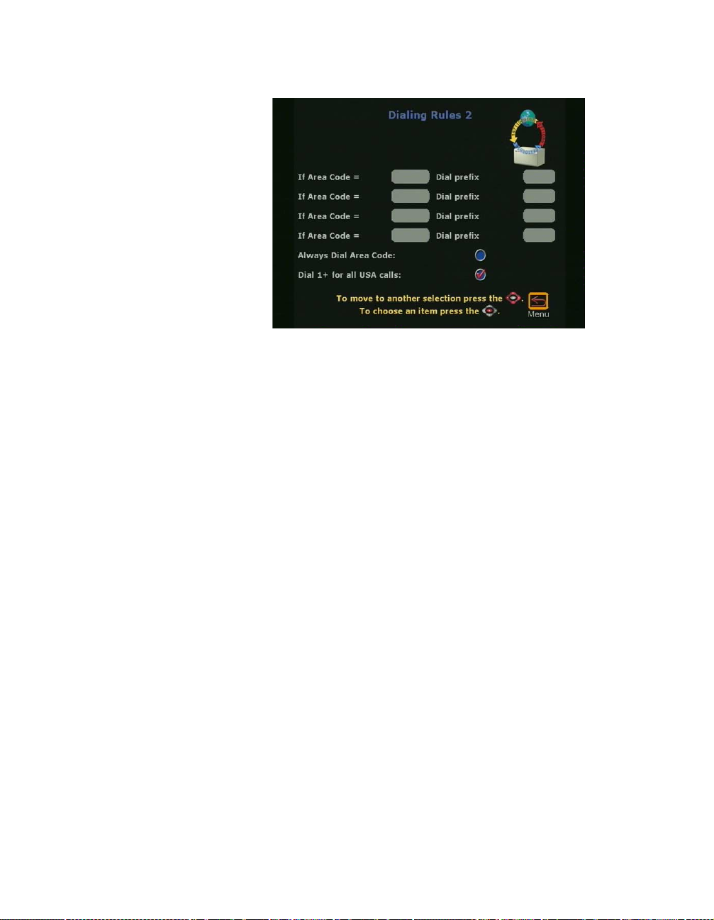
Chapter 2 Optional Configuration s
Figure 2-51. Dialing Rules 2 Screen
If the private network requires a dial prefix to access certain area
codes (or city codes), set these prefixes on this screen. This prefix
is dialed before the area code. For example, some sites require a 9
before dialing a 1-800-xxx-xxxx number.
Global Management
Enable the Always Dial Area Code option if you must dial the area
code to sites that have the same local area code as the ViewStation.
This is sometimes necessary for 10-digit dialing.
The Global Management screen (System Info > Admin Setup >
LAN/H.323 > Global Management) is used to remotely monitor,
configure, and maintain the ViewStation from a remote location. To
use the Global Management feature, your organization must use
Polycom Global Management System
The Global Management screen shown in Figure 2-52 contains
icons used to configure the following global management for the
ViewStation:
• GMS Setup: Configures GMS properties.
•Info 1: Provides for contact and support for the GMS
system.
software.
ViewStation User Guide 84 www.polycom.com
 Loading...