

Page 1

E
CHOFREE
EF400
™
A
COUSTIC
E
CHO
C
ANCELLER
U
SER
M
ANUAL
Page 2

Copyright © 1999 ASPI Digital. All rights reserved. Printed in the United States of America.
Because of technical progress, specifications are subject to change without notice.
EchoFree is a trademark and ASPI is a registered trademark of ASPI Digital.
ASPI Digital - The Sound of DSP
1720 Peachtree Street NW, Suite 220
Atlanta, GA 30309-2439
(404) 892-3200
www.echofree.com
Technical Support:
(404) 892-3200
help@aspi.com
EF400UM-0100-99
Page 3

EF400 U
SER MANUAL
Introduction.... ........ .............. .................... .............. ............. .............. ...........2
Product Features.......................... ............................................ ........ ........... ........... 3
Insta l lation.................. .............. .............. .................... ............. .............. .......4
Preparing................................................................................................................ 4
EF400 Front and Rear Panels................................................................................ 5
Prepar e th e Ro o m ............ .......... ................. .......... ................. ......... ................. ....... 6
Select a Mounting Location.................................................................................... 6
Connect Equipment.. ............................... .......... .................... ..................... .......... ... 6
Configuration..............................................................................................8
Setting the Bandwidth Switch ................................................................................. 8
Setting the Run/Setup Switch .................................................................................. 8
Setting the Phantom Power Switch......................................................................... 8
Calibration....................................................................................................9
Overview................................................................................................................. 9
About Signal Levels................................................................................................ 9
Calibra t io n St ep s ...... .. ... ......... .......... ................. .......... ................. .......... ................ 1 1
Calibra t io n Verifica ti o n ....... .. ... ................. .......... ................. ......... ................. ....... 16
Operati on. .. ........ .................... .............. .................... ............... .................... ..17
Traini n g ..... ... .. ................. .......... ................. .......... ................. ......... ................. ....... 17
The Mut e Bu tt o n .. .. .......... .......... ................. .......... ................. ......... ................. ....... 17
Record and Playback........................................ .......... .......... ............................... ... 17
General Conferencing Guidelines......................................................................... 18
Troubleshooting...........................................................................................19
No Output to Loudspeakers (you can’t hear them) ................................................ 19
No Output to Remote End (they can’t hear you) .................................................... 19
Residual Echo......................................................................................................... 20
Technical Support......................... ........ ................... .................................... ........ ... 22
Technical Specifications ..............................................................................23
Warran ty Informa ti o n . .......................... ........................... ..........................25
Appendix: About AEC ................................................................................27
ASPI Digital, Copyright 1999 1
Page 4

I
NTRODUCTION
EF400 U
SER MANUAL
Congratulations!
About the EF400
User Manual
Product Description
Congratulat ions on your purchas e of the EchoF ree™ EF400 Acousti c Echo Ca ncell er
(AEC). By ch oos ing the EF400, you have gained an exceptional communications system that delivers crisp, clear audio and efficient, comfortable conferencing.
This manual tell s you how to insta ll, conf igure , and calib rat e the EF400 to funct ion in
a hands-free conferencing system. It also provides information about operating and
troubleshooting the EF400.
The EchoFree™ EF400 AEC supports two-way conversations in hands-free communicati ons app lic at ion s. Th e EF4 00 el im ina te s ech oes an d ac ous ti c fe edba ck tha t oc cur
when loudspeaker a udio is picked up by room microphones .
Whether you are using the EF400 in a small cubicle or a large confe rence room, all
parties can communicate simult aneously without ec hoes , switching nois es , clipping
of words, or dropout of speech. A patented state-logic algorithm ensures smooth and
natural communications without typical speakerphone performance problems.
The EF400 employs a subband digital filtering architecture for ec ho ca ncellation.
This architecture provides f aster convergence and b etter p erformance than o t her ec h o
cancellers . It co ntinual ly adapts t o change s in t he envi ronment so tha t part ici pants can
move about freely and volume levels may change during the conversation without
adversely affecting communication quality.
Unlike most other echo cancellers, the EF400 requires no training sequence to lear n a
room’s echo respons e. This means there are no annoying tone bursts at the beginning
of the conversation. After the unit has been ins talled, all you have to do is turn it on.
No further adjustments are requ ired.
You can move the spea ker or mi crophone or chang e rooms wit hout putt ing the EF 400
through a training sequence. This is possible becaus e of the EF400’s advanced acoustic echo cancellation techno logy. And it means the EF400 ada p ts to changes in room
acoustics during conversations quickly for consistent performance throughout the
conversation.
In addition to superior echo cancellation, the EF400 provides high-fidelity audio connections. Thi s allows low-noise, tr ouble-free interaction with professional or co nsumer quality audio equipment.
Warranty
Registration
2 Copyright © 1999, All Rights Reserved
Please take a moment to fill out and return your warranty regis trati on card. This information will help us to provide you with better customer support.
Page 5

I
NTRODUCTION
P
RODUCT FEATURES
• Full-duple x communications that sounds real and natural with no switching,
dropouts, or speech clipping. All parties can be heard simultaneously.
• Based on proven, patented technology.
• Automatic tr aining does not require nois e burs ts or tones for setup.
• Continuous and quick adaptation to changes in room acoustics with a 30dB/s
convergence rate.
• Howling rejection (feedback suppression).
• Long tail time (200 ms) for even difficult rooms.
• Operates with up to 10dB room gain.
• Supports 3.5kHz an d 7kHz speech and audio communications (switch selectable).
• Supports muting without disabling AEC adaptation.
• Balanced, professional line-level input and output permit direct connection to
CODECs and other professional quality equipment.
• Connects to the EF200 Phone Add to make a complete teleconferencing unit.
• Accepts mic-level input (switch selectable).
• Unbalanced record input and playba ck output for connecting external equipment.
• Small footprint f its easily in rollabout carts or on rack tray.
• Easy set up. After input and output levels are calibrated, operation is completely
automatic.
• Tamper proof. No external level controls f or unauthorized users to disturb.
• Continuous a nd quic k ad aptat ion to n ew envir onm ents. Doe s not requ ire memory
to store room settings.
• Guaranteed superior workmanship backed by a full two-ye ar warranty.
• Extended warranty available.
ASPI Digital -
The Sound of DSP
3
Page 6
I
NSTALLATION
REPARING
P
EF400 U
SER MANUAL
The EF400 product packa ge includes the following items:
• EF400 User Manual (this manual)
• EF400 Acoustic Echo Canceller
• External power supply
• Warranty registra tion card
• Flat head trimpot adjuster.
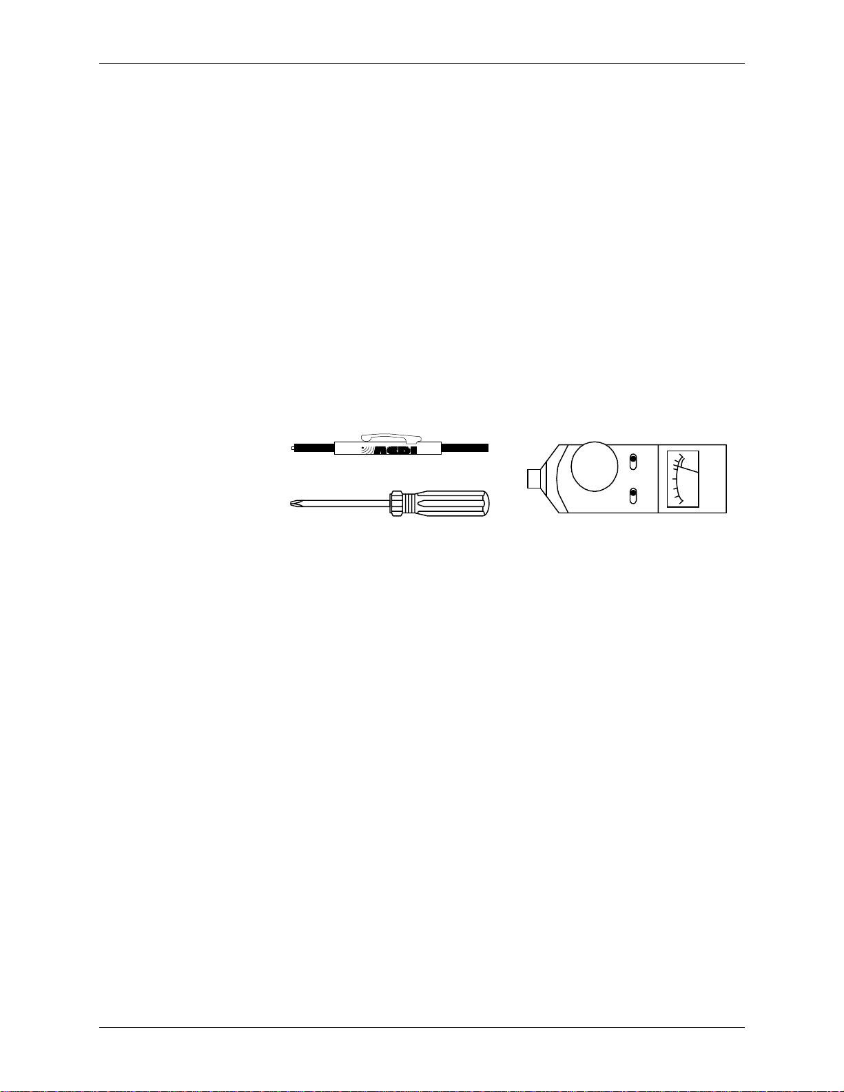
You need the following tools to install and configure the EF400:
• EF400 User Manual (this manual)
• Small Phillips head screwdriver for opening the top of the EF400
• Hand-held SPL meter for measu r ing loudness (such as the Radio Shack 33-2050
Sound Level Meter)
• Small plastic trimpot adjuster for adjusting th e electrical signal levels (included).
+6
RESPONSEWEIGHTING
4
02
2
4
-10
BATT
dB
SOUND LEVEL METER
SCREWDRIVER
OFF
70
RANGE >
SLOW FAST
A C
You need the following additional equipment to create a completely functional system:
• Microphone(s)
• Speaker(s)
• Audio amplifie r (or am plified speaker)
• CODEC and/or EF200 Phone Add
• Audio cables
• Tape recorder or VCR (optional)
• Mute switch (optional)
• RS200 Rack Mount shelf (optional).
4 Copyright © 1999, All Rights Reserved
Page 7
I
NSTALLATION
EF400 F
RONT AND REAR PANELS
MICROPHONE REMOTEPOWER
1 2
1(875,.
12
3
ROOM REMOTE
567891011 12
3
INPUTMIC INPUT SPEAKER OUTPUT OUTPUT
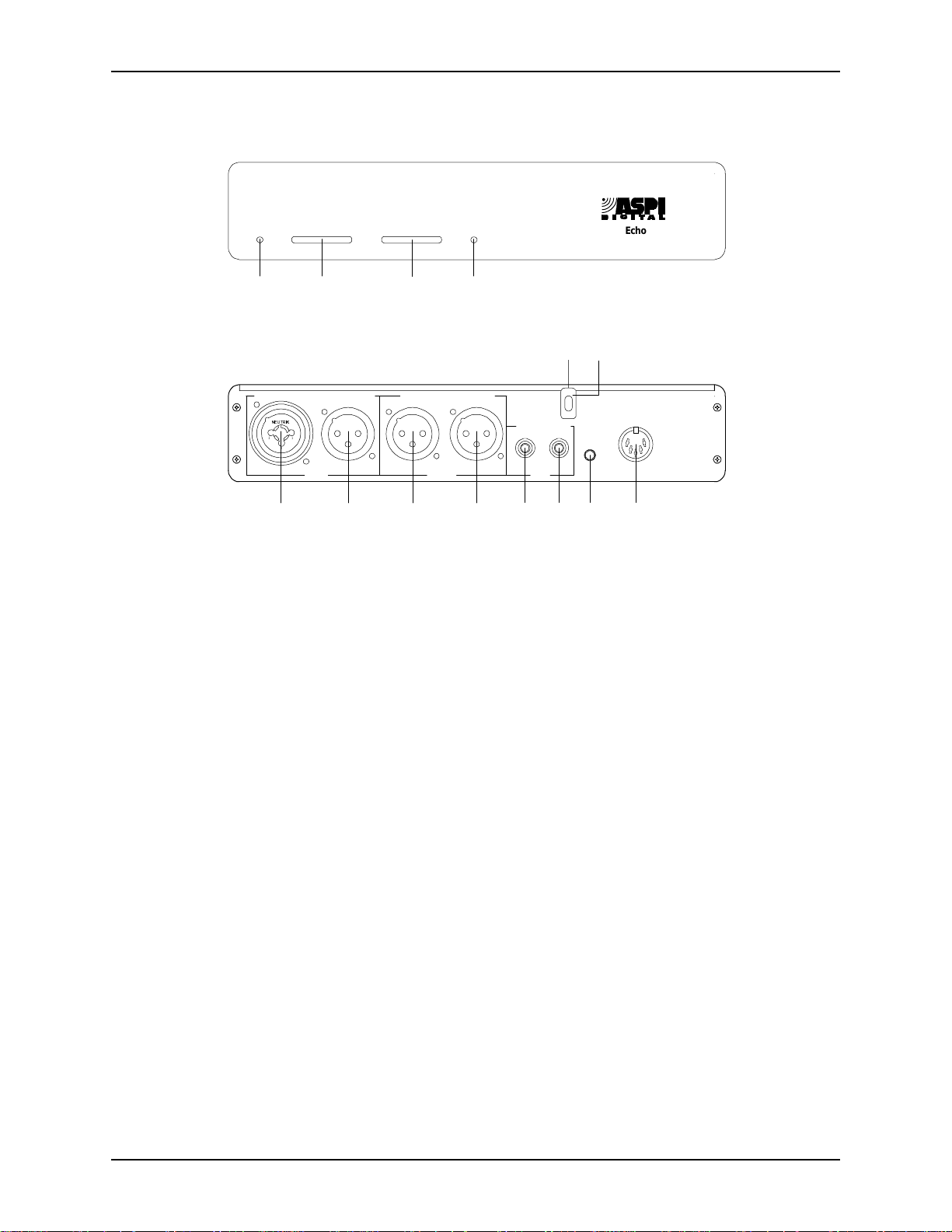
Figure 1. The front and rear pa nel of the EchoFree EF400.
MUTE
4
13
PLAY RECORD
TAPE
MUTE
ROOM
INPUT
T H E
14
S O U N D O F D S
EchoFree
EF400
15
+5,+/-
VDC
P
TM
OWER INDICATOR
1. P
ICROPHONE INPUT LEVEL INDICATOR
2. M
. When LED is green, power is on.
. Displays micr ophone input signal le vel.
See page 12.
EMOTE INPUT LEVEL INDICATOR
3. R
. Displays remote input signal level. See
page 13.
UTE INDICATOR
4. M
. When the LED is blue , local audio is not sent to the remote
connection.
5. M
IC INPUT
. Connects to a mic, mic preamplifier, or mixer. Provides phantom
power to condenser microphones. Configured via the internal phantom power
switch. See page 8.
PEAKER OUTPUT
6. S
. Connects to an audio amplifier or powered speaker. (Line
level output cannot drive a speaker without an amplifier.)
EMOTE INPUT
7. R
EMOTE OUTPUT
8. R
APE PLAYBACK INPUT
9. T
. Connects to the output of a CODEC or EF200 Phone Add.
. Connects to the input of a CODEC or EF200 Phone Add.
. Connects to the output of a tape recorde r, VCR, or other
recording device. This signal is sent to the remote output as well as the speaker
output. See Figure 5 on page 17.
APE RECORD OUTPUT
10. T
. Connects to a recording device. Signals from the remote
and mic inputs (both ends of the conversation) go to the recording device. See
Figure 5 on page 17.
UTE ROOM INPUT
11. M
. Connects to the mute switch (not included but an example
circuit is sh own in Figu re 4 on page 17). Th e mute swit ch turns off the REMOTE
OUTPUT while still allowing adap tation. It prevents local conversations from
being sent to the remote site.
OWER SUPPLY INPUT
12. P
HASSIS LID SCREW
13. C
. Connects to the external power supply.
. Loosen this screw to lower the L
OCK BAR
, open t h e chas-
sis, and make adjustments to the EF400.
14. L
OCK BAR
. Latch es o n to th e C
HASSIS LID SCREW
to keep the lid on.
ASPI Digital -
The Sound of DSP
5
Page 8
P
REPARE THE ROOM
To ensure good acoustics in the room, add carpeting, curtains, or acoustic tiles to the
conferenci ng r oom . Imp roving room acoustics enhances the performanc e of the
EF400 and the sound qualit y and int ellig ibi lit y of local sp eech. Keep ing micr ophone s
near people and away from loud speakers and noise sources (fans, air vents, and projectors for e xample) also improves the performance of the EF400.
S
ELECT A MOUNTING LOCATION
After verifying that you have all the equipment and m aterial required for th e installation, select a moun ting location for the sy st em . You can mount the EF400 on a table
top or an ASPI Digital RS200 Shelf. The RS200 Shelf can suppor t two EF400s
mounted side-by-side, or an EF400 and an EF200 Phone Add for usin g the E F4 00
with a telephone line.
Assemble your too ls and all required and optional equipment in an area that is convenient to the mounting locati on.
C
ONNECT EQUIPMENT
EF400 U
SER MANUAL
Required
Connections
microphone
M
ICROPHONE INPUTSPEAKER OUTPUT
1(875,.
12
3
R
OOM
POWER LOW HIGH VOLUME MIC
POWERED SPEAKER
CODEC/hybrid
I
NPUT
R
EMOTE
TX RX
O
UTPUT
P
LAYRECORD
auto-reverse
VCR
T
APE
TAPE RECORDER
M
R
I
UTE
OOM
NPUT
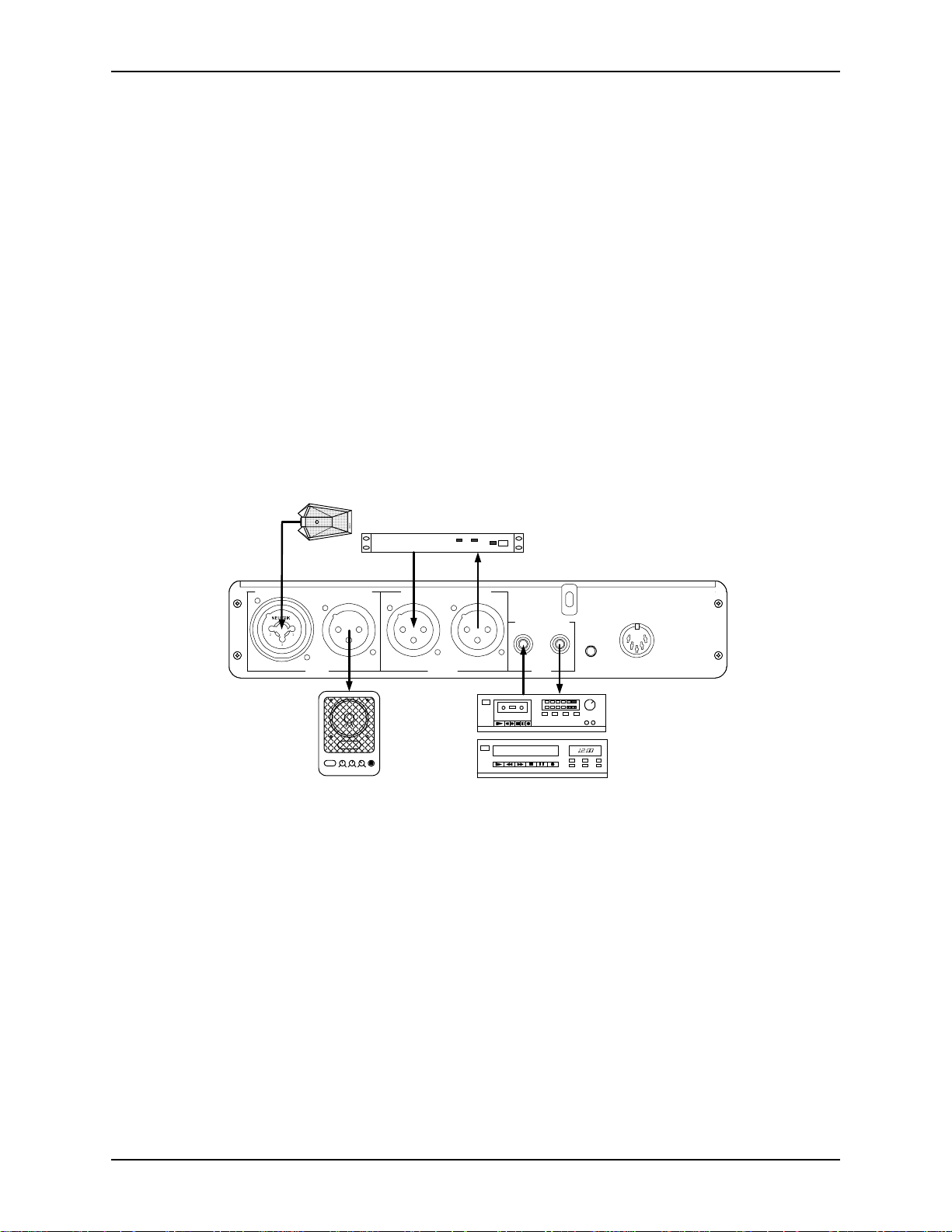
Figure 2. Connection of typical external equipmen t to the EF400.
Certain equi pment and c onnect ions a re requir ed for the EF400 to be fully op era tional .
(Figure 2 depicts typical connections.) Complete the following steps to ma ke all the
required connections:
1. Connect the M
plifier. The M
IC INPUT
IC INPUT
to a microphone or to the output of a microphone pream-
accepts balanced XLR-type or balanced Phone (TRS)
connectors.
2. Connect the S
PEAKER OUTPUT
to the input of an audio amplifier or powered
speaker. This output cannot dri ve an unampl ifi ed speake r. The S
accepts a balanced XLR-type connector.
3. Connect the R
CODEC, or the F
NPUT
accepts a balanced XLR-type connector.
I
4. Connect the R
EMOTE INPUT
ROM
EMOTE OUTPUT
to the output of your terminal equipment, usually a
AEC connection on the EF200 Phone Add. The R
to the input of your terminal equipment, usually a
+5,+/-15
VDC
PEAKER OUTPUT
EMOTE
6 Copyright © 1999, All Rights Reserved
Page 9

I
NSTALLATION
Important!
Optional
Connections
CODEC, or the TO AEC connection on the EF20 0 Phon e Add. The R
UTPUT
O
Verify that the EF400 R
the EF400 R
accepts a balanced XLR-type connector.
EMOTE INPUT
EMOTE OUTPUT
is connected to the input of the CODEC.
is connected to the output of the CODEC and
EMOTE
5. Connect the power supply connector to the exte rnal power supply included with
the EF400.
You may find these connections useful, but they are not required for proper operation
of the EF400.
• Record. To record with a tape recorder or VCR, connect the T
PUT
on the EF400 to the audio input on the recording devi ce. This is an unbal-
APE RECORD OUT
anced RCA connector.
• Playback. To play back through a tape recorder or VCR, connect the T
BACK INPUT
on the EF400 to the audio output on the playback device . This is an
APE PLAY
unbalanced RCA connector.
• Mute. To add mute capability, connect th e M
UTE ROOM INPUT
on the EF400 to a
mute button or ot her swi tching circui t. Thi s is a two-c onducto r mini co nnecto r. If
the switch is closed (that is, the two conductors of the M
shorted), the R
PUT
is not muted. If you do not connect the mute button to the M
NPUT
, the EF400 is not capable of muting audio.
I
EMOTE OUTPUT
is muted. If the switch is ope n, the R
UTE ROOM INPUT
UTE ROOM
are
EMOTE OUT
-
-
-
Important!
You can build a mute button using the schema tic in Figure 4 on page 17.
ASPI Digital -
The Sound of DSP
7
Page 10

C
ONFIGURATION
EF400 U
You must configure s everal options using the DIP switch S7. These options are
described bel ow. Refe r to the EF400 Circ uit Board Layou t on pa ge 12 for t he l ocati on
of DIP switch S7. (You must open the EF400 chassi s to acces s the DIP switches.)
SER MANUAL
NOTE
Important!
ETTING THE BANDWIDTH SWITCH
S
Wide Bandwidth
Narrow Bandwidth
The side of the switch that is down is the side that is selected. For instance, if the
7.0kHz/3.5kHz switch is down on t he 7.0kHz side, the EF400 is operating in 7.0 kHz
mode. The switches rock up a nd down rather than sliding from si de to side.
Switches 1 through 3 are reserved. Keep them in the factory default positions. The
factory default positi ons are ON (1), OFF (2), and OFF (3). A switch is of f if the left
side is presse d down.
Keep this switch in the 7kHz position for most applications.
If you use a wide bandwidth (7kHz) CODE C, set the bandwidth switch to the 7kHz
position. If you connect to wideband and narrowband connections (that is, if yo ur system connects to a wideband video CODEC or a narrowba nd telephone connection
through the EF200 for different calls), set the bandwidth switch to 7kHz.
If you connect only to na rrowband terminals, set the ba ndwidth switch to the 3.5kHz
position. In extreme conditions, you may find that the EF400 works better in the 3.5
kHz mode.
ETTING THE RUN/SETUP SWITCH
S
Whenever you calibrat e the EF400, set the RUN/S
ing normal operation, set the R
Setup mode is active only if the EF400 is reset when the R
ETUP
position. The EF400 may be rese t by chang ing the ba ndwidth s witch bac k and
S
forth. Setup mode is exi ted and normal operation restored when the R
switc h is set to R
ETTING THE PHANTOM POWER SWITCH
S
Condenser and electret microphones need phantom power. Dynamic microphones do
not. Phantom power may damage a dynamic mi crophone. If you are not sure whether
the microphone needs phantom power, check the microphone spec ifications.
Power Required
Power Not Required
If a micropho ne is connected to the MIC I
power, set the P
If a microphone preamplifier or a microphone is connected to the MIC I
ther device requires pha ntom power, set the P
UN
HANTOM POWER
ETUP
switch to S
UN/SETUP
.
switch to P
switch to the RUN position.
NPUT
and the microphone requires phantom
HANTOM
.
HANTOM POWER
ETUP
UN/SETUP
switch to OFF.
position. Dur-
switch is in the
UN/SETUP
NPUT
and nei-
8 Copyright © 1999, All Rights Reserved
Page 11

C
ALIBRATION
C
ALIBRATION
VERVIEW
O
For the EF400 to work effectively, you must calibrate the in put and output signal levels correctly. Calibration is required to relate a loudne ss value (as measured by a
sound-level meter) to the electrical signa l associated with the loudness.
Note
Important!
BOUT SIGNAL LEVELS
A
The calibrati on procedure is required only to adjust the EF400 to accommodate the
electrical characteristics of your conferencing equipment . T he procedure permi ts you
to connect the widest pos sibl e variety of equipment to th e EF400. The cal ibrati on procedure does not train the AEC. The EF400 does not require training.
In calibration mode, the EF400 generates a precise noise signal for measuring the
characteristics and sensitivity of the microphone. You only need to perform this calibration at the initial insta llation. You do not hav e to ca librate the EF400 each time it
is used.
When calibrated for the particular microphone and CODEC setup, the EF400 will
provide years of service without recali bration. If the signal levels are not calibra ted,
the performance of the EF400 may not be satisfactory. When the signal levels are calibrated correctly, the EF400 easily and automatically handl es any type of signals and
change in room acoustics for unparalleled ech o cancellation per formance.
After calibration, the microphone input signal and remote inp ut signal must be at the
same nominal signal level . If these two inp uts diffe r in nomina l leve l by 6dB or more,
the performance of the EF400 will be compromised.
Audio signal levels for the EF400 inputs and out puts are controlled by trim pots ,
which you can see by sliding back the unit’s top cover. These trim pots are lined up
with the appropriate backpanel connector and are labeled (viewed from the front and
left to right) R
PUT
, MIC I
to allow the levels to be adjusted.
ECORD
NPUT
, and MIC G
LAYBACK
, P
EMOTE OUTPUT
, R
AIN
. A plastic trimpot adjuste r is shipped with the EF400
EMOTE INPUT
, R
PEAKER OUT
, S
-
Important!
Important!
ASPI Digital -
The EF400 works with a udio equipment requiring signal leve ls in the range of +4dBu
to -20dBu. This range covers professi onal-audio levels (+4dBu) and consumer-equipment levels (-8dBu or -10dBV). It also allows a further 12dB s ignal attenuati on to 20dBu if required. The most commonly used levels (+ 4, -8, and -20dBu) are labeled
on the trimpots for M
PUT
The markings on outp ut trimpots refer to the lev el that is output on the
corresponding connector. To increas e the level of the room or remote
output, turn the trimpots clockwise towards +4dBu.
The markings on the input trimpots correspond to the levels expected to
be input to the EF400. If the R
the signal turn the t rim pot adju ster clockwis e towa rds -20dBu . Note that
both input and output trimpots must be turned clockwise to boost the
input and output signals, but the text around the output trimpots is in reverse order to
the text around the input trimpots.
The Sound of DSP
IC INPUT
. Refer to Figure 3 on page 10 for additional information.
PEAKER OUTPUT
, S
EMOTE INPUT
EMOTE INPUT
, R
signal is too low, to boost
, and R
EMOTE OUT
-
9
Page 12

1
2
3
RUN
7.0 kHz
OFF
S7
SETUP
3.5 kHz
PHANTOM
RECORD
R17
-8
-6-12
PLAYBACK
-8
R33
REMOTE
OUTPUT
-8
R25
-20-4
SINGLE-TURN POTS.
!
+4-20
TURN CAREFULLY.
R24
DO NOT EXCEED TURNING ARC.
REMOTE
INPUT
-8
-20+4
SPEAKER
OUTPUT
-8
R5
EF400 U
MIC
GAIN
LINE
MIC
+4-20
SENSITIVE
S9
MIC
INPUT
-8
R5
Caution !
USE STATIC
SER MANUAL
-20+4
PRECAUTIONS
!
Figure 3. EF400 Circuit Board La yout
Caution!
Do not damage the EF400’s circuitry. Use the plasti c static-safe trimp ot adjuster
shipped with the unit for all adjustment s. Do not use a metal screwdriver or allow
jewelry, chains , or pendants to contact the E F4 00 enc los ure. Metal tools and obje cts
may cause a short circuit, damage the circuit board, and void your wa rranty.
Caution!
When using the supplied trimpot adjus ter to adjust signal levels, do not touch any
other components on the EF400 circuit board with the trimpot adjuster.
TM
EchoFree
A quality product made in the USA
EF400
10 Copyright © 1999, All Rights Reserved
Page 13

C
ALIBRATION
C
ALIBRATION STEPS
Step 1—Prepare the
EF400
Important!
Follow the s teps listed here to prepare the EF400 for calibration of the signal levels.
SCREWDRIVER
1. Power down the EF400.
2. If you have not already done so, connect the microphone (or mixer) to the M
NPUT
and the room speaker amplifier (or powered speaker) to the S
I
PUT
PEAKER OUT
3. If you have not already done so, connect the terminal equipment to the R
NPUT
I
EMOTE OUTPUT
and R
as shown in Figure 2.
IC
EMOTE
4. Turn the volume of the amplifier/powered speaker down to zero.
5. Loosen the C
OCK BAR
the L
HASSIS LID SCREW
down.
in the upper middle of the backpanel, and slide
6. Slide the top cover ba ck to expose the line of trimpots. These trimpots are lined
up with the appropria te backpanel connect or and are labeled. (Refer to Figure 3
on page 10. )
7. Identif y the DIP switch S7 in the center left of the EF400. Set the R
ETUP
switch to the S
UTPUT
O
(which is used to s et the microphone input level) when the system is
position. This genera te s a white nois e signal on the S
UN/SETUP
PEAKER
powered up.
Now you are ready to calibra te the EF400 signal level s. Do not apply power to the
EF400 until direc ted to do so in the following instructions.
-
Step 2—Calibrate
Speaker Output
You must match the spe aker output level to the specified nomina l input level of your
powered speaker or amplifier.
1. Determine the app ropriate nominal signa l level for your powered speake r or
loudspeaker amplifier. The specifications for your power ed speaker or amplifie r
should include the nominal input si gnal level. If you do not have nominal level
specifications for your loudspeaker/am plifier, or if the specifications a re unclear,
use these guidelines. If you are using a powered speaker, it probably requires a 8dBu input level. If you are using an amplifier and the connectors are RCA
phono connectors, use -8dBu. If the connectors are balanced (most likely XLRtype connectors), use 0dBu (this is half way between the +4 and -8 marks around
PEAKER OUTPUT
the S
2. Turn the S
PEAKER OUTPUT
trimpot).
trimpot until the trimpot slot points to the marking
on the EF400 circuit board corresponding to the nominal level selecte d in the
previous step. If the input signal level for your powered speaker or amplifier are
specified in terms of dBu or dBm, this number corresponds to the numbers (+4,
0, -8, -20) printed on the EF400 circuit board. If the speaker or amplifier level is
ASPI Digital -
The Sound of DSP
11
Page 14

EF400 U
SER MANUAL
specified in terms of dBV, add 2 to the dBV number to translate it to dBu (for
example.–10dBV corre sponds roughly to -8 dBu).
After the S
PEAKER OUTPUT
is calibrated, you can calibrate the MIC I
NPUT
level .
Step 3—Calibrate
Microphone Input
Important!
Note
In this step, you ca librate the mic input level using a 73dB SPL noise signal (generated by the EF400). You want to illuminate the first yellow LED but not the second
yellow LED on the front panel M
ICROPHONE INPUT LEVEL INDICATOR
OFF
70
RANGE >
SLOW FAST
A C
RESPONSEWEIGHTING
.
+6
4
BATT
02
dB
2
4
-10
SOUND LEVEL METER
You use the built-in noise generator and your S PL meter to set the mic input level .
Extraneous noise (such as conversa tio n) should not be au dible in the local confe rence
room, as it would make it very difficult to get consistent readings on the SPL meter
ICROPHONE INPUT LEVEL INDICATOR
and M
You use different trimpots to calibrate the MIC I
.
NPUT
level , depending on whether
the input signal is line le vel (from a microphone preamplifier) or mic level (directly
from a microphone).
1. Locate the M
IC/LINE
switch S9, the MIC I
NPUT
trimpot, and the MIC G
AIN
trim-
pot. (They ar e to your right and nea r the back of the cir cuit board in line with the
IC INPUT
M
• If you are using a microphone mixer or preamplifier, set the M
connector).
IC/LINE
switch to
the LINE position.
• If you are connecti ng a microphone directly to the EF400, set the M
IC/LINE
switc h to the MI C position.
Note
If the MIC/L
INE
switch is in th e L
trimpot to a range between -20dBu and +4dBu input signal le vel. If the M
IC
switch is in the M
position, you will be adjusting t he MIC G
INE
position, you will be adjusting the MIC I
AIN
trimpot to a range
NPUT
IC/LINE
between +15 dB and + 60 dB gain . ( This level a ccommodate s m icr ophone s ignal l evels
between -33dBu and -80dBu.)
2. Turn the appropriate trimpot to it s minimum setting.
•If the M
IC/LINE
switch is in th e L
pot for inpu t level adjustment. Turn the M
INE
position, you will use the MIC I
IC INPUT
trimpot fully counterclock-
NPUT
trim-
wise (to the +4 position).
•If the M
IC/LINE
switch is in the MIC position, you will use the MIC G
for input level adjustment. Turn the M
IC GAIN
trimpot counterclockwise several
AIN
trimpot
times (this is a multi-turn pot).
3. Positio n the room microphone so that no people or objects are between it an d the
loudspeaker. Be careful not to stand dire ctly between the loud sp eaker and the
microphone while adjusting the EF400. The micr ophone should be approxi mately 1m from the loudspeaker (if possible), and th e loudspeaker and the microphone should be pointing towards each other.
4. Set the r ange on the SPL met er to 7 0dB, C we ighte d, f ast response . Place the S PL
12 Copyright © 1999, All Rights Reserved
Page 15

C
ALIBRATION
meter beside the microphone. Point the SPL meter toward the loudspeaker.
5. Turn on the EF400 (you wi ll hear white noise on the loudspea ker), and adjust the
volume on the loud spe aker until the SPL meter reads 73dB. Stand to the side of
the SPL meter (rathe r than in fro nt of it or behind it ) whil e readi ng it, s o that your
body does not interfere with the reading.
6. Adjust the appropriate trimpot and observe the LEDs on the front panel M
PHONE INPUT LEVEL INDICATOR
•If the M
IC/LINE
switch is in th e L
.
INE
position, tur n the MIC I
NPUT
trimpot clock-
ICRO
wise.
• If the M
IC/LINE
switch is in the MIC position, turn the MIC G
AIN
trimpot clockwise. You may need to turn this pot s everal times.
Continue to a djust the trimpo t until all thr ee green L EDs and only the firs t yellow
LED are illumina ted. The second yellow LED should not be illuminated (it may
flicker occasionally).
-
Note
Important!
Step 4—Calibrate
Remote Input
Important!
If adjustment of the trimpot appears to have no ef fect on the M
EVEL INDICATOR
L
, return to Step 1 and verify that you are adjusting the correct trim-
ICROPHONE INPUT
pot.
7. Move your loudspeaker and microphone back to their norm al operating positions.
8. Set the R
UN/SETUP
switch b ack to t he RUN position. The E F400 i s now in no rmal
operating mode.
Avoid pointing the microphone directly at the speaker when in normal operating
mode. This alignment reduces the maximum acoustic gain allowed in your conferencing setup.
This step matches the remote input level to the microphone input level by matching
the level on the R
NPUT LEVEL INDICATOR
I
EMOTE INPUT
R
EMOTE INPUT LEVEL INDICATOR
trimpot to -20 dBu (fully clockwise).
to the level on th e M
. If the EF400 is conne cted t o an EF200 Pho ne Add , turn t he
ICROPHONE
During this s tep, you must be able to co nverse with someone at t he remote end of the
communications link. It is also important to elimi nate extraneous noise (such as other
people speaking) at both ends of the communicat ions link, as such noise woul d interfere with M
TOR
readings.
ICROPHONE INPUT LEVEL INDICATOR
EMOTE INPUT LEVEL INDICA
and R
-
ASPI Digital -
1. Position yourself so that you can easily se e the EF400 front panel signal leve l
2. Instruct the person at the remote end to sit at a normal distance from the remote
3. While the person at the remote end is talking, adjust the R
The Sound of DSP
indicators and reach the R
EMOTE INPUT
trimpot. Now move the local room
microphone so tha t it is facing you at a normal speaking distance (usually 1–1. 5
meter s) wh en yo u ar e in th i s po s i ti o n.
microphone (usually 1–1.5 meters). Have this person read something to you,
using a normal speaki ng voice.
EMOTE INPUT
trimpot
until n ormal co nver sation l ev el c onsiste ntl y i llumina te s the t hre e gree n LEDs an d
only the first yellow LED on the R
EMOTE INPUT LEVEL INDICATOR
. Louder
13
Page 16

EF400 U
SER MANUAL
speech will cause the second yellow LED to pulse on and off.. The level on the
indicator will vary as the speech energy from the remote end varies; the indicator
indicates peak e n erg y in a similar f ashion to a V U me t er .
4. Now speak in a normal voice wit h the person at the remote end. You should still
be positioned as des cribed in Step 1, facing the microphone at distance of 1–1.5
meters. Observe the M
EVEL INDICATOR
L
. Both indicators should show si mi lar levels of activity in r eac-
ICROPHONE INPUT LEVEL INDICATOR
and R
EMOTE INPUT
tion to passages of similar speech strength.
Note
Step 5—Calibrate
Remote Output
If the person at the remote end cannot hear you clearly when you spe ak at a normal
level, turn the R
EMOTE OUTPUT
trimpot clockwise (towards +4dBu). Conti nue the
clockwise adjustment (up to +4dBu) until they can hear you clearly.
5. If the R
than the M
EMOTE INPUT LEVEL INDICATOR
ICROPHONE INPUT LEVEL INDICATOR
counterclockwis e (towards +4dBu) to compensate. If the R
NDICATOR
I
EVEL INDICATOR
L
consistently illuminates fewer LEDs than the M
, turn the R
EMOTE INPUT
consistently illuminates more LEDs
, turn the R
EMOTE INPUT
EMOTE INPUT LEVEL
ICROPHONE INPUT
trimpot
trimpot clockwise (towards -20 dBu)
to comp e nsate.
6. If you moved your microphone in Step 1, now move it back to its normal operating position.
This step s how s you ho w to mat ch the re mote output l eve l to t he r emote in put lev el by
adjusting the R
EMOTE OUTPUT
Phone Add, turn the R
Set the R
for the R
EMOTE OUTPUT
EMOTE INPUT
EMOTE OUTPUT
level. Turn the R
trimpot. If you are using the EF400 with an EF200
trimpot to -20 dBu (fully counterclockwise).
trimpot to the sam e nume ric le ve l as y ou pre vious ly se le cted
EMOTE OUTPUT
trimpo t until the trimpot slot
points to the marks on the EF400 circuit board that correspond to the level you
selecte d on the R
EMOTE INPUT
trimpot.
Important!
Note
Remember that the numeric markings around the R
reverse order to those around the R
EMOTE INPUT
The input and output audio levels at the rem ote equipment may not be symmetric
EMOTE OUTPUT
trimpot.
trimpot are in
because of imbalances in the remote equipment or the interposing commu nications
EMOTE OUT
EMOTE OUT
Step 6—Tape
equipment. You ca n compens ate for such imbalances by adjusting the R
PUT
level. If the audio s ignal at the remote end is overdr iven and distorted aft er you
set the R
EMOTE OUTPUT
level, adjust the R
EMOTE OUTPUT
trimpot down (counter -
clockwise). If the audio signal at the remote end is too low, adjust the R
PUT
trimpot up (clockwise).
The tape pla yback and record levels should not require adjustment.
Playback and Record
Levels
14 Copyright © 1999, All Rights Reserved
-
-
Page 17

C
ALIBRATION
Step 7—Install
EF400 AEC Unit
APE PLAY INPUT
The T
APE RECORD OUTPUT
and T
interface to consumer grade audio
equipment such as a tape recorder or VCR. These connectors are designed for -8dBu
nominal signal level. Set the trimpots for these connections to -8dBu for most applications. If th ese leve ls prov e unsati sfactory fo r any r eason, a djust them up or down by
several dB.
Slide the top cove r f orward on the EF400 and secure it with th e lock bar and chassis
lid screw. The EF400 is now ready for tabletop or rackmount installation.
SCREWDRIVER
Tabletop Installation
The EF400 is equipped with four rubber feet that allow installation on a flat surface
such as a tabletop.
1. Remove the adhesive backing on the rubber feet.
2. Install the r ubber feet in the circular cutouts on the EF400 baseplat e.
Rackmount Installation
1. After you complete th e configuration and cal ibration procedures, place the
EF400 on the ASPI Digital RS200 Shelf.
2. Secure the EF400 to th e RS200 shelf using four of the small scre ws (4-40 x ¼")
provided with the RS200. If one EF400 is to be mounted on t he s helf, place it in
the center. If two units are to be mounted, mount them size by si de.
3. If only one EF400 is moun ted, attach the two small faceplates supplied with the
RS200 to each side of the EF400. Use four more of the small screws to secure
the face plates.
4. Secure the RS200 shelf to the rack us ing all four large screws (10-32 x ½") sup-
plied with the RS200.
5. The EF400 power supply block should be placed securely in the base of the rack
unit. To eliminate any risk of the power cable being pulled out of the EF400 rear
panel connector, use the plastic Ty-Wraps prov ided with the RS200 to provide
strain relie f by securing the power cable to the rack upright at the rear of the
EF400.
ASPI Digital -
Caution!
Failure to use all four screws to attach the RS200 s helf to the rack may result in
uneven lo ading and cause a safety hazard.
Caution!
Ensure that the power supply is securel y loc ated suc h that it cannot be come dis lodged
and fall. Such a fall could caus e personal injury or equipment failure.
Caution!
When mounting an EF400 in a rack, consideration should be given to airflow and
operating ambient temperatures inside the rack. To ensure safe operation of the
EF400, ambient operating temperatures inside the rack should not exceed 50 degrees
Celsius. Allow 2 inc hes of open space in front of the EF400, an d four inches behind
the unit for prop er ve ntila tion. Equipm ent should not be inst alle d in t he rack in s uch a
way as to interfere with ventilation to the EF400.
The Sound of DSP
15
Page 18

EF400 U
SER MANUAL
Caution!
Caution!
C
ALIBRATION VERIFICATION
Consideration should be given to the connection of the equipme nt to the supply circuit and the effect that overloading of circuits could have on overcurrent protection
and supply wiring . Appropriat e conside rat ion of equip ment na meplate ratings should
be used when addressing this concern.
Reliable earthing of rack-mounted equipment should be mainta ined. Particular att ention should be given to supply connections oth er than direct connection to the Branch
(use of power strips).
During normal operation (a conference), obs erve the front panel M
EVEL INDICATOR
L
EMOTE INPUT LEVEL INDICATOR
and R
. The red LED should not
ICROPHONE INPUT
flicker or illuminate on either meter. If either red LED illuminates or flickers frequently, re duce the co rrespo nding input le ve l. Both signa l-leve l met ers shoul d exhibi t
similar beha vi or. The cali bration proc ess accomm odates a nomina l spe ech le ve l at t he
room microphone (normal speec h at 1m to 2m from the microphone).
During low-lev el speech, several green LEDs may il luminate. During norma l speech
in a conference, the first yellow LED should ill uminate frequently, and the second
yellow LED should flicker regularly during periods of louder speech. Extreme and
unusual levels (for example, a participant shouting into the micr ophone) may overdrive the input level and cause the red LED to illuminate. This is not cause for concern unless you expect this condition to be the normal operating mode!
Similar spe ech activity leve ls at the local and remote ends should cause the same
number of LEDs to illumi nate on both signal strength meters. If the R
EVEL INDICATOR
L
TOR
, adjust the R
up the level on the R
NDICATOR
I
adjus t th e R
is consistently lower than the M
EMOTE INPUT
EMOTE INPUT LEVEL INDICATOR
is cons istently h ig her than th e M
EMOTE INPUT
down the level on the R
trimpot clockwise (toward the -20dBu m ark) to bring
trimpot countercloc k wise (toward the +4 m ark ) to bring
EMOTE INPUT LEVEL INDICATOR
ICROPHONE INPUT LEVEL INDICA
. If the R
ICROPHONE INPUT LEVEL INDICATOR
EMOTE INPUT LEVEL
.
EMOTE INPUT
,
-
The remote eq uipment may be set up us ing a different procedure, and may be producing signals at a different level than the nominal input level of your terminal equipment. This would cause your terminal equipment to produce signals lower th an its
nominal level. Thus, the setting of the R
EMOTE INPUT
trimpot may differ from the
output signal level specificat ions for your terminal equipment. For example, your terminal equipme nt may specify a nominal output level of -8dBu, but you may have to
set the R
EMOTE INPUT
trimpot to -20dBu to bring the remote signa l to the same level
as the loca l microphone.
16 Copyright © 1999, All Rights Reserved
Page 19

O
PERATION
O
PERATION
RAINING
T
The EF400 operat es a utoma tica lly. Us er in te racti on is not require d unles s t he opti ona l
mute button h as been installed. Below are inst ructions for using the EF400 and ensuring a successful conference.
Because of the EF400’s superior AEC technology, no training sequence i s necessary.
After the EF400 is powered up, it automatically adapts to the room’s acoustics.
THE M
UTE BUTTON
Note
ECORD AND PLAYBACK
R
When pressed, the mute button prevents local speech from being transmitted to the
EMOTE OUTPUT
R
though its output is muted.
The mute signal can be provided by any normally open contact. The contact can be a
switch on a micropho ne or control panel or provided by a rela y-closure output on
another piece of equipm ent.
If the s w itch is open (a), the EF4 00 is not muted. If the switch is closed (b ), the
EMOTE OUTPUT
R
If you mute the EF400 externally (such as with the P
APE RECORD
the T
If you have a tape recorder connected to the EF400’s T
BACK
jacks, you can record confer ences or play back material to parties on the both
ends. When you record, bot h ends of the conversation are recorded on the tape. When
you play a tape, the audio is sent to the remote end as well as the loca l end. If you
have a standard tape deck, si mply press play or record to play back audio or record a
conference. The figure below shows how the record and playback signa ls are routed.
and the T
Figure 4. Schematic of mute button.
and T
output will not be muted.
APE RECORD
a) Unmuted b) Muted
APE RECORD
output. The EF400 co ntinues to adapt even
are muted.
RIVACY
feature on the EF200),
APE RECORD
and T
APE PLAY
-
ASPI Digital -
The Sound of DSP
Speaker Output
Microphone Input
Figure 5. Record and playback signal paths.
AEC
Remote Input
Remote Output
PlaybackRecord
17
Page 20

G
ENERAL CONFERENCING GUIDELINES
The EF400 adapts exc eptionally well to changes in room acous tics, but audio quality
will be even b e t te r when co n f er en c e pa r ti ci p an t s fol lo w th ese guidelines:
1. Sit or stand in one place and near a microphone. Moving ar ound the room and
toward or away from the microphone while talking may ca use speech audio to
fade in and out.
2. Speak clearly and directly toward the microphone.
3. Keep the microphone away from noise sources such as computer fans, air ducts,
or coffee makers. Excessive noise can be annoying to people on the remote end
and reduce inte lligibility. It can also hamper th e adaptation logic and degrade
EF400 performance.
EF400 U
SER MANUAL
18 Copyright © 1999, All Rights Reserved
Page 21

T
ROUBLESHOOTING
T
ROUBLESHOOTING
NO O
NO O
UTPUT TO LOUDSPEAKERS (YOU CAN’T HEAR THEM
Check the R
the EF400 is receiv ing a s ignal. In this case, the problem is between the EF400 an d
the speaker.
If there is no activity on the R
a signal. In this case, the problem is between the EF400 and the microphone on the
remote end.
Check the CODEC (or EF200) output by connecting it directly to the amplifier or
powered speaker. If you hear nothing, the EF400 is not causing the problem and the
source of the problem is elsewhere in the system .
Make sure the CODEC or EF200 output is connected to the R
Make sure the CODEC or EF200 is turned on and a call is establis hed.
Make sure everything on the remote end is working properly.
Make sure the cables are not broken. Check the cable pinouts.
Make sure the S
input.
Make sure the amplifier or powered speaker is on and that the volume is at an appro-
priate le vel.
UTPUT TO REMOTE END (THEY CAN’T HEAR YOU
EMOTE
input level indicator. If the LED bar graph meter shows activity,
EMOTE
input level indicator, the EF400 is not rece iving
PEAKER OUTPUT
is connected to the amplif ier (or powere d speaker)
)
)
EMOTE INPUT
.
Check the M
when you speak into the microphone. If LEDs show activit y when you speak into the
microphone, the EF400 is receiving the mi crophone signal. This means the remote
end is not receiving a signal from the EF400.
Check the R
(turn the speaker down to avoid howling). If the speaker emits sound when you sp eak
into the mic r ophone, the signa l is making it through the EF400. Thi s means there is a
problem with the CODEC, the CODEC connectio n, or a de vice on the remote end.
If the M
not receiving the microphone signa l. This means there is a problem with the microphone or preamplifier.
If there is no speaker output, unplug the mute button. If this fixes the problem, the
mute button is dam aged or incompatible with the EF400.
If you are not using a microphone mix er an d the mic r ophone requires phantom
power, make sure it i s enabled i n the EF400. Make sure the phantom power voltage is
compatible with the microphone.
Make sure the R
Make sure the CODEC or EF200 is turned on.
Make sure everything on the remote end is working properly.
Make sure the cables are not broken. Check the cable pinouts.
ICROPHONE INPUT LEVEL INDICATOR
EMOTE OUTPUT
ICROPHONE INPUT LEVEL INDICATOR
EMOTE OUTPUT
by connecting it to the amplifier or powered speaker
is connected to the CODEC or EF200 input .
, and make sure it displays activity
does not display acti vity, the EF400 is
ASPI Digital -
The Sound of DSP
19
Page 22

R
ESIDUAL ECHO
EF400 U
SER MANUAL
Make sure the microphone mixer (if present) is on and th at the volume is up. Make
sure the micropho ne is plugged into it. If the microphone requires phantom power,
make sure that the microphone mixer is providing it to the microphone.
Make sure the microphone (or mixer) is plugged into the M
ICROPHONE INPUT
.
You may hear residual ec ho if system levels are not set properly. Improper level s ettings anywhere in the audio path can introduce nonlinearities that hamper the operation of the EF400. If you hear res idual echo, one of the following conditions may be
causing the pr oblem.
Reverberation vs.
Echo
Low Remote Level
and/or High
Loudspeaker Gain
Do not confuse the residual ec ho of remote speech with the reverberation of local
speech. Reverberation of local speech is caused when the speech signal arrives at the
microphone via s everal pa th s (the direc t path a nd mult iple refl ecti ons fro m sur faces i n
the room). This is a local room phenomenon that gives the s peaker’s voice a hollow
or resonant sound (as heard at the remote end).
Reverberat ion is not an artifact of the echo ca nceller. It is mainly affected by the distance of the microphone from the speech source and by the resonances of the room.
While reverberation can be unpleasant , it is not compensated for by the AEC, which
only removes reflec tions of remote speech.
You cannot remove the effe cts of reverb erati on by changi ng the EF400’s s ettin gs, but
you can minimize reverberation by moving microphones closer to speakers and, if
necessary, adding acoustical treatment to the room. If multiple micr ophones are
open, it may be necessar y to use an automatic micro phone mixer to reduce reverberation.
The most common cause of poor echo cancellation performance is cause d by a low
EMOTE INPUT
R
level f r om the CODEC. Generally, if the remote level is too low, this
is compensated by increasing the gain to the loudspeaker. This results in a much
louder signal being returned to the microphone than is being received on the remote
end. This large level imbalance caus es res idual echo, beca use it looks like there is
much more local audio than remote audio (it looks like the people in the room are
talking).
You can check for low remote input signal levels by observing the R
EVEL INDICATOR
L
yellow LED to flicker. Make sure you are looking at the R
CATOR
, and not the M
during a normal conference . Th e re mot e speech should cause one
EMOTE INPUT LEVEL INDI
ICROPHONE INPUT LEVEL INDICATOR
. If the remote input level is
EMOTE INPUT
too low, increase the gain on the Remote Input trimpot, and lower the gain to the
loudspeaker.
-
Even with a reasonabl e remot e input le vel, i t is stil l poss ible to c ause res idual echo by
having too muc h gain between the loudspeaker and microphone. Watch the R
NPUT LEVEL METER
I
ICROPHONE INPUT LEVEL METER
and M
simultaneous ly during
EMOTE
remote speech . Both meters should show some ac tivity. The microphone activity is
caused by the loudspeaker signal picked up by the microphone. If the microphone
level is much louder, there may be residual echoes. The gain betwee n the loudspeaker and microphone can be reduced by lowering the loudspeaker volume, adding
acoustical treatment to the room, or by moving microphones and loudspeakers to provide more is olation.
20 Copyright © 1999, All Rights Reserved
Page 23

T
ROUBLESHOOTING
See the Calibration section for more information on setting microphone and remote
signal levels.
Excessive
Microphone
Preamplification
Insufficient
Microphone
Preamplification
Note
For the EF400 to ada pt effec tivel y, sa turati on (ove rload or c lippin g) must not occu r at
the A-D converter supplying the microphone input. Saturation introduces nonlinear
signal distortions into what the AEC expects is a linearly echoed version of the
remote sp eech.
Nonlinear distortion causes a degradation or dive rgence of the AEC’s internal model
of the room acoustics . In this situa tion, the EF400 canno t effect ively c ancel room echoes and a substantial amount of echo may be heard by the remot e party.
You can check for excessive microphone amplification by observing the front panel
ICROPHONE INPUT LEVEL INDICATOR
M
LED should illuminate frequently, and the second yellow LED should flicker regularly during periods of louder speech. If the second yellow LED is illuminated constantly during normal speech or i f the re d LED i llumi nates or even fl ickers, red uce th e
microphone input level.
If you adjust the M
NPUT
signal level to match it. Refer to Microphon e and Remote Signal Levels do not
I
Match on pa ge 21 and Calibration Verification on page 17 for more information.
Grossly insufficie nt microphone gain degrades EF400 performance and weakens the
out-bound spe ech powe r leve l. T his ha s the effect o f re ducing t he signal-t o-noi se r atio
of the mic rophone signal, which is analogous to raisi ng the background noise level in
the room. Because this noise is uncorrelated with the ec hoes within the room , the
EF400’s ability to adapt and cancel echoes is comp rom ised.
A second effect of insufficient microph one ga in is that the power of the microphone
input signal may be subs tantially lower tha n that of the remote input signal. This
reduces the ability of the decision logic to determine whether the AEC should be in
transmit, receive, or double-t alk m ode. This effe ct may re duce t he effect ivene ss o f th e
EF400 in canceling ec hoes.
ICROPHONE INPUT
during a normal conference. The first yellow
signal, you may need to readjust the R
EMOTE
Loudspeaker
Nonlinearity
ASPI Digital -
The Sound of DSP
Note
You can check for insufficient microphone preamplification by observing the front
panel M
tion. The first yellow LED should illuminate frequently, and the second yellow LED
should flicker regularly during periods of louder speech. If the M
L
speech, increase the microphone input level.
If you adjust the M
I
Match on pa ge 21 and Calibration Verification on page 17 for more information.
Overdriving the loudspeaker may distort the loudspeaker signal and caus e ineffective
AEC operation. The EF400 re lies on the linearity of the acoustic feedback path—DA, amplifier, lou ds peaker, microphone, preampl ifier, and A-D—to cancel acousti c
echoes. If you overdri ve the speaker, the acous tic reflections picked up by the micro-
ICROPHONE INPUT LEVEL INDICATOR
EVEL INDICATOR
NPUT
signal level to match it. Refer to Microphon e and Remote Signal Levels do not
never illuminat es beyond one or two green LEDs during normal
ICROPHONE INPUT
signal, you may need to readjust the R
during normal confere ncing conversa-
ICROPHONE INPUT
EMOTE
21
Page 24

T
ECHNICAL SUPPORT
EF400 U
phone do not match the signal fed to the speaker. They ar e distorted copies of this signal. The EF400 cannot effectively cancel this distorted signal.
If you suspect the louds peaker is introducing nonlinearities into the room acoustic
path, take these steps to minimize its influence on the echo canceller:
• Keep the loudspea ker’s volume level at less than three-eighths of full scale. If
higher volume is required, the EF400 should operate effectively a t volume settings of up to 50 perc ent of full scale. At more than 50 percent, m ost audio systems and loudspea kers introduce significant nonlinearities. The EF400 may not
adapt under these conditions, and echoes may be he ard.
• If the l oudspeaker has a bass control, lower it. Excessive bass can cause a boomy
effect that is nonline ar. In addition, excessive bass may cause substantial
mechanical coupling to the microphone through vibrations induced in the housings and support st ructures.
• Increase the sepa ration distance between the microphone and loudspeaker. The
EF400 handles up to 10dB of ac oustic gain between the speaker and the microphone. You may be exceedi ng this limit if the speaker is pointed directly at the
microphone or if the speaker volume is excessive. (S peaker placement is not critical, but it shoul d not be pointed directly at the microphone.)
SER MANUAL
If these troubleshooting guidelines don’t resolve the problem you are experiencing
with the EF400, please check our web site (http:/ /www.echofree.com/support) for the
most current technical support information. If you have further questions , please contact us at:
Applicat ions Engineering
ASPI Digital
1720 Peachtree St . NW Suit e 220
Atlanta, GA 30309-2439
Phone: (404) 892-3200
Fax: (404) 892-2512
Email: help@aspi.com
Before contacting us, please review the warranty and repair policy on page 24.
22 Copyright © 1999, All Rights Reserved
Page 25

T
ECHNICAL SPECIFICATIONS
T
ECHNICAL SPECIFICATIONS
ECHANICAL SPECIFICATIONS
M
Dimensions 8.15” (207mm) W x 8.40” (213 mm) L x 1.57 ” (40mm) H (1/ 2 rack
unit)
Weight 2 lb. (1 kg)
Connectors 4-wire: XLR inputs/outputs. Aux: RCA (phono).
LECTRICAL SPECIFICATIONS
E
Power External tra ns f ormer (supplied): 100-240VAC; 47-63 Hz
Power Consumption 5W
Room and Remote Line Inputs balanced bridging > 10 kΩ inpu t impedance; +4 dBu nomina l level
(adjustable to -20 dBu)
Room and Remote Line Outputs balanced; 50 Ω (designed to drive > 600 Ω inputs); +4 dBu nomi-
nal (adjustable to -20 dBu)
Playback Input unbalanced; > 10 kΩ input inpedance; -8 dBu nom inal level
Record Output unbalanced; 75 Ω output impedance (designed to drive > 10 kΩ
inputs); -8 dBu nominal level
Microphone Input (mic level) balanced; > 10 k Ω input impedance; -30 dBu nominal (ad justable
to -60 dBu)
Headroom 18 dB
Phantom Power 24 V (switch selectable)
ERFORMANCE SPECIFICATIONS
P
Frequency Response 125-7,250 Hz, +/- 2 dB. Selectable to 3.4 kHz bandwidth.
Total Cancellation 65 dB
Convergence rate 30 dB/sec
Echo cancellation s pan 200 ms
ASPI Digital -
The Sound of DSP
23
Page 26

C
OMPL IANCE
EF400 U
The EF400 is compliant with the ITU G.167 recommendations for acoustic echo cancellers, CE requi rem ents, and FCC part 15 requirements .
SER MANUAL
FCC Part 15
Warning!
This equi pm ent has been tested and found to comply with the limits for a Class A digital device, pursuant to Part 15 of the FCC Rules. These lim its are designed to provide reasonable protection against harmful interfere nce when the equipment is
operated in a commercial e nvironment. This equipment gene rates, uses, and can radiate radio frequency energy and, if not installed and used in accordance with the
instruction manual, may cause harmful interfe renc e to radio communications. Oper ation of this equipment in a re sidential area is likely to cause harmful interference in
which case the user will be re quired to correct the interfe rence at his own expense.
FCC Regulations state that any unauthorized changes or modifications to this equipment not expressly approved by the manufacturer could void the user’s authorizatio n
to oper ate this e quipme nt .
The EF400 also complie s with the CE standards EN50081-1, EN50082-1. and
EN60950. Conformity of the equipment with those guidelines is attested by the CE
mark.
24 Copyright © 1999, All Rights Reserved
Page 27

W
ARRANTY INFORMATION
W
ARRANTY INFORMATION
What is covered
For how long
What we will do
Limitations
Any defect in materials or workmanship.
Two years.
If your ASPI Digi tal product is defect ive and returned within two years of the date of
purchase, we will repa ir or, at our option, replace it at no charge to you.
If we repair your ASPI Digital product, we may use new or reconditioned replacement parts. If we choos e to rep lace your ASPI Dig ita l product , we may repl ace it with
a new or recondi tioned one of the sam e or simi lar des ign. The repair o r repl acemen t is
warranted for either (a ) 90 days or (b) th e remainder of t he origin al two-ye ar warranty
period, whichever is longer.
ASPI Digital s hall not be respons ible for spe cial, inci dental , i ndirec t, or c onseq uentia l
damages resulting from any breach of warranty, or under any other legal theory,
including but not limited to loss of profits, downtime, goodwill, damage to or replacement of equipment and property, and any cost of recovering, reprogra mming, or
reproducing any pro gram or data stored in or used with ASPI Digital products.
Some states do not allow limitations on how long an implied warranty la sts, or the
exclusion of incident al or consequential damages, so the a bove exclusions or limitations may not apply to you.
What we ask you to
do
What this warranty
does not cover
To obtain warranty service for your ASPI Digital product, call us at (404) 892-3200
or fax us at (40 4) 892 -2512 and we wi ll is sue a Return Ma teria l Authori zati on nu mber
(RMA#). Use the original packa ging materials to return the product. Ship the product
prepaid to:
ASPI Digital
Attention: Warra nty Repair
RMA# (Mus t be on pac kage)
1720 Peachtree Stree t NW, Suite 220
Atlanta, Geor gia 30309-2439 USA
Please be sure to include yo ur name, company, address, phone number, and a description of the problem. After repairing or replacing your ASPI Digital product , we will
ship it to you via a surface carr ier of our choice at no cost to you. If you wish it
shipped via a specific carrier at your cost, you must arrange it when you obtain the
RMA#.
Repair or replacement of your ASPI Digital produc t is your exclusive remedy.
This warranty does not cover defects resulting from accidents, damage while in transit to our service location, alterations, unauthorized repair, failure to follow instruc-
ASPI Digital -
The Sound of DSP
25
Page 28

EF400 U
tions, misuse, fire, flood, lightning, acts of God, or use in those countries where such
use violates Part 779 of the Export Administrat ion Regulations of the United States
Department of Commerce.
If your ASPI Digit al product is not covere d by our wa rranty, call us at (404 ) 892-3200
or fax us at ( 404) 892-2512 for a dvice a bout whe the r we will r epair y our ASP I Digita l
product and for other repair inform ation, including charges. ASPI Digital, in its sole
discretion, may replace rather than repair your ASPI Digital product with a new or
reconditioned one of the same or similar design. The repair or replacement is warranted for 90 days.
The limited warranties and remedies set forth above are exclusive and in lieu of all
other warranties, whether oral or written, express or implied. ASPI Digital specifically disclaims any and all implied warranties, in cluding, without lim itation, the warranties of m erchantability and fitness for a pa rticular purpose.
SER MANUAL
No User Serviceable
Parts
State Law Rights
This product conta ins no user serviceable parts. Please contac t ASPI Digital for
repairs. Attempts to repair this product by an unauthorized technician will void your
warranty.
This limited warranty gives you specific legal rights, and you amy have other rights
that may vary from state to state.
26 Copyright © 1999, All Rights Reserved
Page 29

A
PPENDIX
: A
BOUT
AEC
A
PPENDIX
: A
BOUT
AEC
Effective hands-free communicati on involves the use of a microphone to pick up the
local speec h signa l and a lo uds peake r to projec t t he spe ech input from the remote site .
There are several problems associated with having a microphone and louds peaker
enabled at the sa me time. In addition to picking up the local spee ch s ignal, the microphone also picks up reflections of the loudspeaker output signal. The sp ee ch s ignal
from the remote end is amplified and passed to the loudspeaker. From here it is projected out int o the local room and reflected ba ck into the microphone after being colored by the acoustic character of the room and all its occupants. This reflec ted signal
is perceived by the lis tener at the remote end as echo. It can be annoying and
extremely dis tracting and may even render sens ible conversation im possible.
If this fe edback of the reflected signal is strong enough and if there is feedback from
the remote end (for exampl e, using an open loudspeaker/microphone combination),
this can lead to howling. Howling is a condition in which the louds peaker output
becomes a loud howl . Ho wling is ext remel y un pleasan t to t he human auditor y s ystem,
and it can cause seve re damage to the audio equipment.
Typical inexpensive speakerphones simply avoid these problems. They prov ide only
half-dupl ex communication links, meaning that only one end has a communication
path at any given time. The decision of which party should get the act ive link is determined by the sign al energy at each end. When one e nd is active, the other end cannot
become active until the signal level at the first end drops. There are many drawbacks
to this system. For example, a talkative individua l can monopolize the line a nd prevent anyone else from getting a word in edgewise. Another drawback is tha t the
acoustic gain of the system must be limited to estimate the local signal energy. This is
so that energy in the loudspeaker signal is not perceived as local signal energy.
Acoustic ech o canc ellat ion ac tivel y remov es th e refle cted echo fro m the signal pi cke d
up by the microphone before transmitting the echo-canceled signal to the remote e nd.
It does this by form ing an int ernal mode l of the acousti c trans fer function between the
signal fed to the loudspeaker and that picked up by the microphone, and applying this
model to the si gnal that the AEC receives from the remo te end. This proces sed version of the remote signal is then subtracted from the signal that the AEC receives
from the local microphone to remove the reflected loudspeaker signal from the local
microphone signa l. Thus AEC allows full-duplex communications over an open
microphone/ loudspeaker combination.
An AEC must learn the loudspeaker -to-microph one acoustic respo nse function for the
room it is servicing in order to cancel echoes. The EF400 AEC does not use noise to
train the echo canceller. Rathe r, it continuously trains on the normal exchange of
speech during the conversation. This results in a more natural flow of conversation
from the beginning of the meeting.
AEC adaptation can be roughly divi ded into two phases: large, rapid changes a re
required to adapt to major acoustical changes (such as moving to a new room);
smaller changes are required to adapt to minor perturbations (such as people moving
and doors opening ). When an AEC is f irs t powered up in a room or moved to a new
location, it needs to adapt from it s uni nitialized state to learn the new acoustics of its
surroundings . A good AEC has a state machine that adapts to this level of acoustic al
change quickly and unobtrusively by determining when it is in the receive state and
adapting r apidly during that sta te.
The state machine of a medi ocre or poor AEC is not as decisive or may even make
incorrect decisions during this critical phase. As a re sult, the AEC remains unconverged too long or, in extreme cases, never properly adapts. Some manufacturers of
ASPI Digital -
The Sound of DSP
27
Page 30

EF400 U
echo cancell ers force the user to store the room characteristics after the initial convergence. This compensates for the fact that the echo canceller is not capable of converging quickly to major ac oustical changes. T he EF400 does not have this flaw.
Other AE Cs compensate for inade q u acies in their state machines by restri cting the
rate of change and the amount of change that they allow in thei r ada ptive filters. This
prevents the AEC from going too far out of convergence by adapting too rapidly
when it is confuse d by a major disturba nce, while all owin g it to trac k relat ively minor
changes such as a door opening or slow movement of people in the room. In this scenario, the AEC must undergo a rapid training procedure to learn the room from its
uninitialized state. Once trained, it adapts to small acoustical changes, but major
changes require retraining. This training usually takes the form of a loud burst of
noise or a sequenc e of tones, which the AEC uses to adapt to the gross acoustical
characteristi cs of its environment.
The most complex and difficult task of an effective AEC is reliably determining when
to permit its internal ac oustic model to adapt to changes in the acoustic character of
the local room. Such changes occur when volume level s are changed; people move
about; doors are opened or closed; the loudspea ker or the microphone is moved; and
so on. Adaptation should only occur when in receive mode (for example, when the
local party is s ilent and the remote party is talking). Inaccu rate mode decisions cause
the AEC’s internal model to diverge and echoes are no t ef fectively canceled.
Inaccuracies in this decision proce ss can cause another significant problem, one that
is handled very elegantly by the EF400. In addition to reducing the effectiveness of
the echo cancellation, inaccurate state or mode decisions may introduc e artifacts into
the transmit ted or received spe ech si gnals . Words may be cli pped or exhi bit dropouts .
Switch loss or center clipping, which are nonlinear processes, may be applied to a
speech signal in the wrong mode. This causes chirping or warbling artifacts that can
be annoying and dis tracting. This can be noticeable in any mode, but particula r ly in
doubletalk (both parties talking simultaneously). The EF400 AEC fe atures patented
state-mac hine log ic so advance d tha t it per mits natura l, undis t orted doub le talk as we ll
as enabling fast, accurat e ad a pt at i on . St at e tr a n sit io n s ar e smooth and no n i nt ru s i ve
and gain during doubletalk is gently and unobtrusively ramped down by a maximum
of 3dB.
SER MANUAL
The EF400 employs a subba nd digital filtering technique to achieve faster conve rgence than other echo cancellers. This allows the EF400 to adapt ra pidly and unobtrusively to changing acoustic conditions. People can move about freely during the
conversation without degrading communications quality.
The EF400 also automatically adapts to changes in the placement of both the loudspeaker and microphone and to changes in loudspeaker volume. The system integrator is freed from the design constraints of most echo cancellers , an d end us ers can
arrange their space as they d esire.
The specifi cations of most AECs require an acoustic room gain of 0d B or lower. This
limits louds pea ker output and restric ts microphone placement and gain. The EF400
AEC can operate at room gain s of up to 10dB, which all ows 10 times gr eater acou stic
power output. This per mits great fle xibility in micro phone and loudsp eaker placement
and volume adjustment.
28 Copyright © 1999, All Rights Reserved
Page 31

A
PPENDIX
C
ONNECTOR PINOUTS
: A
BOUT
1(875,.
AEC
ICROPHONE INPUT
M
The microphone inp ut a ccep ts eithe r XL R or 1/4” P hone b alanc ed male
connectors.
12
3
XLR: 1 - shield; 2 - positive signal; 3 - negative signal.
1/4”: Tip - positive signal; Ring - negative signal; Sleeve - shield.
EMOTE INPUT
R
The remote input accepts an XLR balanced male co n nector.
12
3
XLR: 1 - shield; 2 - positive signal; 3 - negative signal.
PEAKER OUTPUT AND REMOTE OUTPUT
S
The speaker and remote outputs accept XLR balanced female connectors.
1
2
3
XLR: 1 - shield; 2 - positive signal; 3 - negative signal.
ECORD OUTPUT AND PLAYBACK INPUT
R
The record output and pla yback input accept RCA male con nec tors.
RCA: 1 - positive signal; 2 - ground.
UTE ROOM INPUT
M
The mute button input accepts a 3.5 mm mini mail connector. The tip
and sleeve shoul d be s horted together to mute the system.
OWER SUPPLY INPUT
P
1
3
45
2
The power supply input ac cepts a 5-pin DIN male connector .
Only use a power supply provided by ASPI Digital.
ASPI Digital -
The Sound of DSP
Power: 1 - ground; 2 - ground; 3 - +5Vdc; 4 - -15Vdc; 5 - +15Vdc.
29
Page 32

B
LOCK DIAGRAM
EF400 U
SER MANUAL
Speaker
Output
Mic Input
Remote
Input
AEC
Remote
Output
Record Playback
30 Copyright © 1999, All Rights Reserved
 Loading...