

Page 1

Vortex EF2280
Applications and Presets Guide
Page 2

Copyright © 2001 Polycom, Inc. All rights reserved. Printed in the United States of America. Because of technical
progress, specifications are subject to change without notice.
®
The Polycom logo and Vortex
are registered trademarks of Polycom, Inc..
Polycom, Inc.
Installed Voice Business Group
1720 Peachtree Street NW, Suite 220
Atlanta, GA 30309-2439
Phone: (800) 932-2774, (404) 892-3200
Fax: (404) 892-2512
www.aspi.com
Technical Support:
(800) 932-2774
vortex@polycom.com
VORTEXAPPGUIDE-0100-01
Page 3

VORTEX® APPLICATIONS AND PRESETS GUIDE
Introduction....................................................................................................2
Building Your System with Multiple Vortexes® ..........................................3
1. Assign Inputs....................................................................................................... 3
2. Assign Outputs.................................................................................................... 3
3. Configure the submatrix ..................................................................................... 3
4. Configure Your Echo Canceller Reference ........................................................ 4
Automixer Settings for Multiple Vortexes............................................................... 5
Connecting Multiple Vortexes ................................................................................ 7
Presets ............................................................................................................10
Polycom, Inc., Copyright 2001 Technical Support: (800) 932-2774 1
Page 4

NTRODUCTION
I
INTRODUCTION
This manual describes useful application information and the factory presets of the
®
Vo r t e x
• Building Your System with Multiple Vortexes® outlines things you need to con-
•Presets shows Factory Presets 0-6 in block diagram form and matrix settings.
. The following is an overview of each section:
sider as you build a system with mulitple Vortex units.
These are meant to be used as examples. Vortex Factory Presets include the following:
• Factory Preset 0: D
EFAULT
. Inputs 1-8 direct out; Inputs A-D mix minus to
Outputs A-D for room audio, codec, Phone Add, and/or program audio.
• Factory Preset 1: D
• Factory Preset 2: S
EFAULT
PLIT
, S
. Default configuration with stereo.
TEREO
. Vortex split between 2 rooms. Inputs 1-4, Output 1
go to Room 1; Inputs 5-8, Output 5 to Room 2. Input/Output A-B and Input/
Output C-D for codec and Phone Add in each room.
• Factory Preset 3: R
ESERVED
• Factory Preset 4: 8 M
.
ICS/ZONE
. For applications with 8 microphones per
loudspeaker zone.
• Factory Preset 5: 8/Z
• Factory Preset 6: 4 M
, S
ONE
TEREO
ICS/ZONE
. 8 mics/zone with stereo.
. For applications with 4 microphones per
loudspeaker zone.
• Factory Preset 7-12: R
• Factory Preset 13: P
ASSTHROUGH MIC
ESERVED
for future use.
. Passthrough mode (Inputs 1-8, A-D
are direct out) with Inputs 1-8 set to Mic level. Everything else is disabled.
• Factory Preset 14: P
ASSTHROUGH LINE
. Passthrough mode (Inputs 1-8, A-D
are direct out) with Inputs 1-8 set to Line level. Everything else is disabled.
• Factory Preset 15 B
LANK SLATE
. All crosspoints muted. Everything dis-
abled.
Vortex
®
Applications and Presets Guide 2 Technical Support: (800) 932-2774
Page 5

BUILDING YOUR SYSTEM WITH MULTIPLE VOR-
UILDING YOUR SYSTEM WITH
B
The following is a checklist for building a system with multiple Vortexes:
1. Assign Inputs.
2. Assign Outputs.
3. Configure submatrix (the EF Bus).
4. Configure your echo canceller reference.
1. A
SSIGN INPUTS
Assign each audio source to an input. Remember to include the conferencing equipment such as the EF200 Phone Add or a video codec and any program audio.
2. A
SSIGN OUTPUTS
Try to assign as many outputs as you can to each Vortex to make a simpler submatrix.
Remember that Outputs 1-8 can also be used as outputs of the matrix. The bussing
can get very complicated very quickly if you choose to spread your outputs over several units.
ULTIPLE VORTEXES
M
®
3. C
ONFIGURE THE SUBMATRIX
To link multiple Vortex devices together, use the submatrix on the EF Bus.
The EF Bus
The EF Bus is a high speed, low delay digital bus that includes the W, X, Y, and Z
audio busses as well as the echo canceller reference and remote control information
(for other Vortexes) and can link up to 8 Vortex devices. All busses include NOM
information and can be used for sharing microphone inputs, or for sharing mono or
stereo program information.
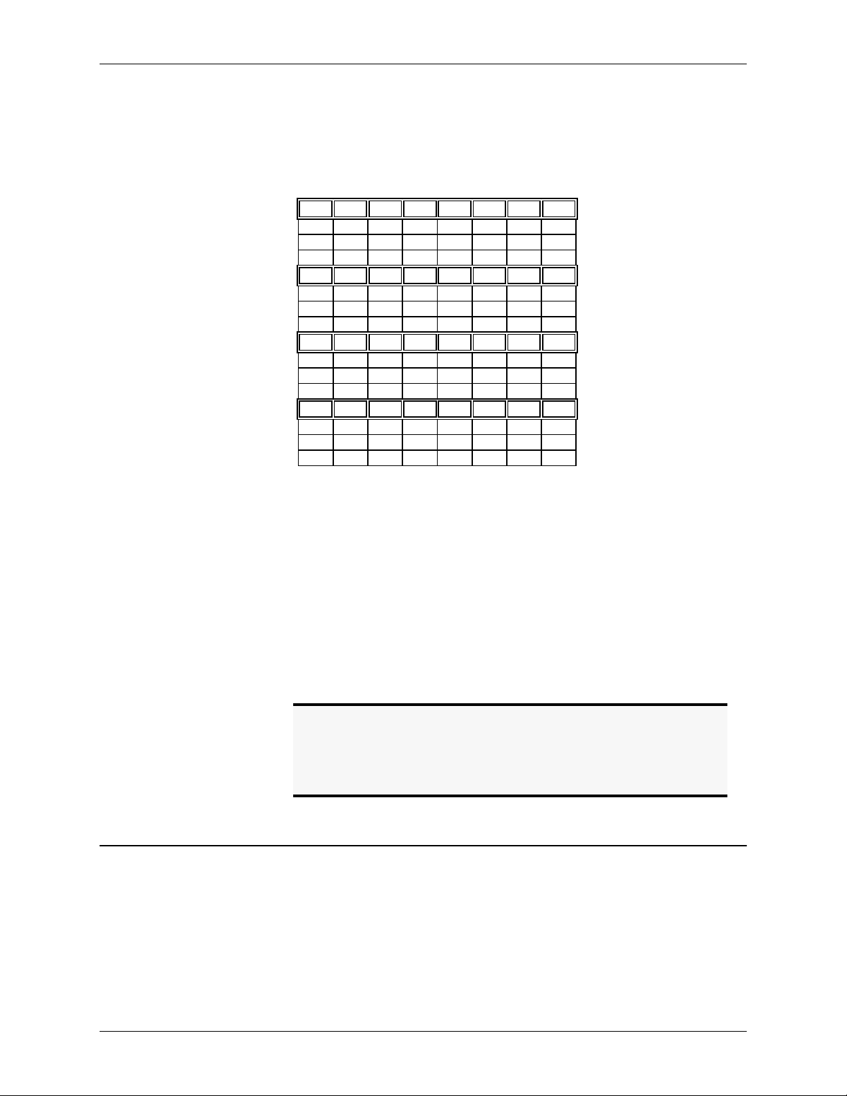
Crosspoint Mix Minus Bus.
output mixes (W, X, Y, and Z) and place them on the bus. Each device also can create
three input mixes each from the W, X, Y, and Z busses of the other devices (for a total
of 12 mixes). The mixes can have crosspoint gains on the signals from the other
devices. See Figure 1 below. All 12 mixes become inputs to the main matrix and can
Each Vortex device in the system can create four
© Polycom, Inc. 3 Vortex
®
Applications and Preset s Guide
Page 6
BUILDING YOUR SYSTEM WITH MULTIPLE VOR-
be mixed with the other inputs to create Outputs 1-8, A-D, Ref 1, Ref 2, and W, X, Y,
and Z bus outputs.
Submatrix
Bus W
Bus X X
Bus Y Y
Bus Z Z
WB0WB1WB2WB3WB4WB5WB6WB7
0XB1XB2XB3XB4XB5XB6XB7
B
0YB1YB2YB3YB4YB5YB6YB7
B
0ZB1ZB2ZB3ZB4ZB5ZB6ZB7
B
Figure 1. W, X, Y, and Z submatrices.
EF Bus Reference.
same echo canceller reference, one device should be designated to put its echo canceller reference (either Ref 1 or Ref 2) on the EF bus to be used as the EF Bus Reference.
All other Vortexes
cellers, or they can use their own internal references. The references may include a
mix of any input, with crosspoint gains, including W, X, Y, and Z busses.
In a system with multiple devices, if all devices need the
may use the EF bus reference as the reference for their echo can-
NOM Bus.
All busses on the EF Bus contain NOM information. See “NOM
Active” on page 29 of the Vortex Reference Manual for more information on how
NOM attenuation is applied.
Note.
The EF Bus must be connected so that the EF BUS OUT of one
Vortex device is connected to the EF B
Connecting EF B
EF B
US OUT
US IN
) will not work. See“Connector Pinouts” on
page 43 for pinout of Cat 5 cable.
4. C
ONFIGURE YOUR ECHO CANCELLER REFERENCE
Review what inputs need to be included in your echo canceller reference — See
“Build Your Echo Canceller Reference (if not using Preset 0)” on page 13. of the Vortex Reference Manual. Remember that each microphone needs an echo canceller reference. If all microphones are in the same room and use the same reference,
configure the echo canceller reference on one Vortex and assign it to the EF Bus as
the EF Bus Reference. Only one Vortex out of multiple units linked together can put
®
Vortex
Applications and Presets Guide 4 Technical Support: (800) 932-2774
of another Vortex.
US IN
to another EF BUS IN (or EF BUS OUT to
Page 7
BUILDING YOUR SYSTEM WITH MULTIPLE VOR-
an echo canceller reference on the EF Bus. For each additional unit, assign the echo
canceller reference to use the EF Bus Reference.
For systems with more than one room, you will need to use the W, X, Y, or Z subbusses to share the echo canceller reference in your additional rooms if the EF Bus
Reference has already been assigned to the EF Bus.
A
UTOMIXER SETTINGS FOR MULTIPLE VORTEXES
When using more than one Vortex in your room system, you have several possibilities
for how you configure the automixer. Each Vortex can operate as one of the following:
• One automixer, independent of other Vortexes linked to it
• Two automixers, independent of other Vortexes linked to it
• One large automixer, sharing automixer functions with other Vortexes linked to it
• Two large automixers, sharing automixer functions with other Vortexes linked to
it
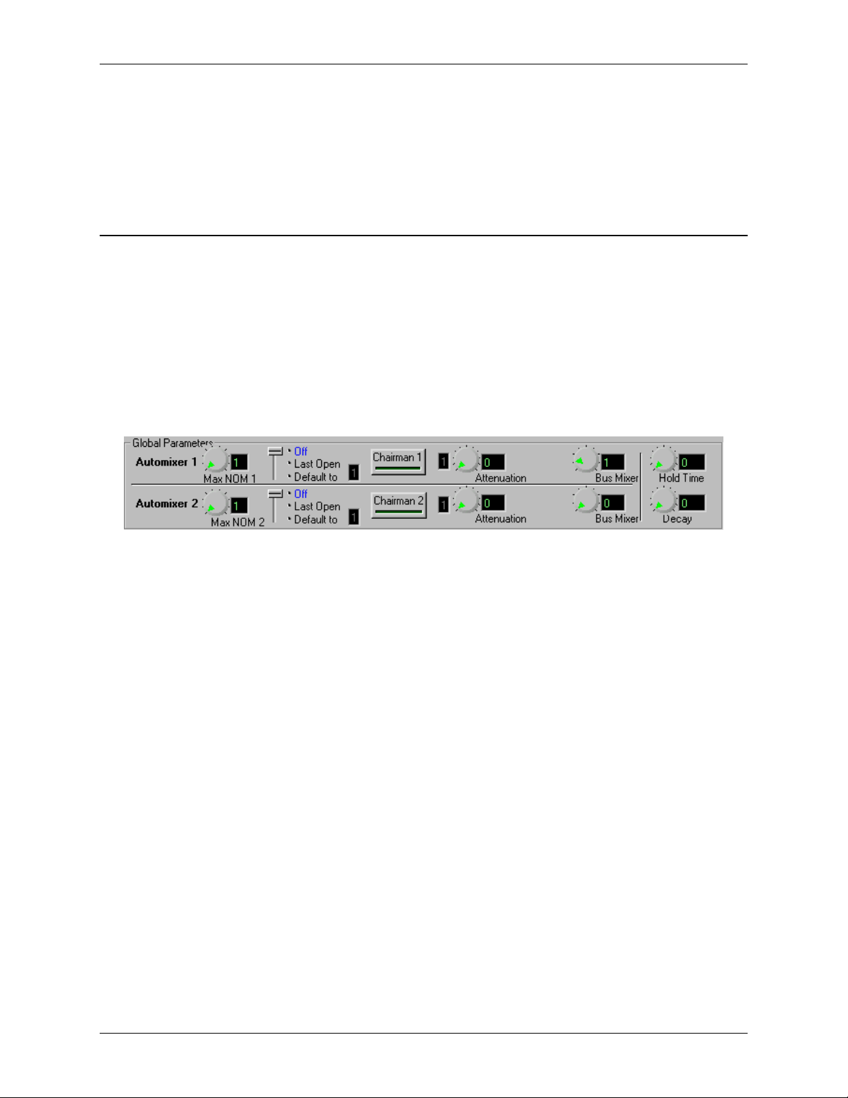
Figure 2. Vortex Automixer Global Parameters in Conference Composer Software
Automixer and Bus
Mixer Settings
Operating as an
Independent
Automixer
To operate the Vortex in any of the above possibilites, two global parameters need to
be changed: the A
parameter chooses which automixer the input channel will be on (this is changed
either on the A
page).
The B
US MIXER
of the eight EF Bus automixer groups. For example, consider three Vortexes each of
which has four microphones assigned to Automixer 1 and 4 microphones assigned to
Automixer 2. Now, if each of these Vortexes sets their Automixer 1 to have Bus
Mixer 5 (the Bus Mixer is also referred to as the Bus ID), then the three automixers
(one from each Vortex) will work as a single automixer containing 12 (3 x 4) microphones. Setting B
Bus.
To set the Vortex to operate as an independent automixer (or two independent mixers), set the B
automixer group currently in use on the EF Bus.
UTOMIXER
UTOMIXER
parameter is used to assign one of the two internal automixers to one
US MIXER
US MIXER
and the BUS M
page in Conference Composer or on the M
to 0 means that the automixer is not grouped on the EF
parameter to 0, or to a number that is different from any other
IXER
(see Figure 2). The A
ATRIX MIXER
UTOMIXER
© Polycom, Inc. 5 Vortex
®
Applications and Preset s Guide
Page 8

BUILDING YOUR SYSTEM WITH MULTIPLE VOR-
Operating as One
Automixer with
Multiple Vortexes
Example: Room
Combining
To set the Vortex to operate as one automixer across several Vortexes, set the BUS
M
parameter on all Vortexes to the same automixer group.
IXER
Let’s take a room combining setup as an example. You have 3 rooms, each with 8
microphones, therefore needing 3 Vortexes. For the purposes of this example, the 3
rooms can operate as 3 separate rooms, 2 rooms with 12 mics each, or one large room.
When the system is split into 3 Rooms, the B
US MIXER
option should have the fol-
lowing settings:
R
OOM
V
ORTEX
ID A
UTOMIXERBUS MIXER
M
ICS
100 AM1 0 1-8
201 AM1 0 1-8
302 AM1 0 1-8
Table 1: B
US MIXER
settings for 3 separate rooms each with 8 microphones operating
independently
When split into 2 Rooms:
R
OOM
V
ORTEX
ID A
UTOMIXERBUS MIXER
M
ICS
100 AM1 1 1-8
201 AM1 1 1-4
201 AM2 2 5-8
302 AM2 2 1-8
Table 2: B
US MIXER
settings for 2 rooms with 12 microphones each
And finally, all combined into one room:
R
OOM
V
ORTEX
ID A
UTOMIXERBUS MIXER
M
ICS
100 AM1 3 1-8
201 AM1 3 1-8
302 AM1 3 1-8
Table 3: B
US MIXER
settings for one room with 24 microphones
The various room setups can be saved in the user defined presets or can be changed
with macros.
Vortex
®
Applications and Presets Guide 6 Technical Support: (800) 932-2774
Page 9

C
ONNECTING MULTIPLE VORTEXES
Up to 8 Vortexes can be linked together at one time. Each unit in the chain must have
a unique Device ID. Use the EF Bus to link multiple Vortexes together.
The following steps should be followed to connect the EF Bus:
• Connect the RS-232 remote control device to the first Vortex in the chain.
• Connect the provided Cat-5 cable between the EF B
and the EF B
BUILDING YOUR SYSTEM WITH MULTIPLE VOR-
of the second device.
US IN
US OUT
of the first device,
Terminating the
Vortex
Note.
The EF Bus must be connected so that the EF Bus In of one
box is connected to the EF Bus Out of another. Connecting
the EF Bus In to another EF Bus In (or Out to Out) will not
work.
• Connect another Cat-5 cable between the EF B
the EF B
• Terminate the chain of Vortexes using the instructions below.
The Vortex must be terminated with the provided EF Bus terminator. Place a terminator in the EF B
last device. If you lose the terminator provided with your Vortex unit, see “Making an
EF Bus Terminator” on page 45 for information and instructions on how to make one.
of the third device, and so on.
US IN
of the first device in the chain and also in the EF BUS OUT of the
US IN
US OUT
of the second device and
© Polycom, Inc. 7 Vortex
®
Applications and Preset s Guide
Page 10

EF Bus Terminator
BUILDING YOUR SYSTEM WITH MULTIPLE VOR-
Cat-5 cable
Cat-5 cable
...
Cat-5 cable
EF Bus Terminator
Figure 3. Connecting and terminating multiple Vortexes.
The Vortex does not have to be terminated if you are using a single unit not connected
together with another Vortex.
Vortex
®
Applications and Presets Guide 8 Technical Support: (800) 932-2774
Page 11

BUILDING YOUR SYSTEM WITH MULTIPLE VOR-
Connecting the
Vortex with Other
EchoFree Devices
If you are linking multiple Vortexes, you must use the EF bus to link the Vortexes to
each other. If you are linking a Vortex to other EchoFree devices, such as the EF200
Phone Add, for RS-232 control, use the ASPI bus. See Figure 4 below. The ASPI
Bus does not need to be terminated.
Out 1
Out 2
Out 3
Out 4
Out 5
Out 6
Out 7
Out 8
®
Out A
Out B
Out C
Out D
EF Bus OutEF Bus In
Out 1
Out 2
Out 3
Out 4
Out 5
Out 6
Out 7
Out 8
®
Out A
Out B
Out C
Out D
EF Bus OutEF Bus In
EF Bus
Terminator
From AEC
From Rem.
EF200
ASPI
Bus In
From AEC
From Rem.
EF200
ASPI
Bus In
From AEC
From Rem.
EF200
ASPI
Bus In
To AEC
To Rem.
Phone
ASPI
Bus Out
To AEC
To Rem.
Phone
ASPI
Bus Out
To AEC
To Rem.
Phone
ASPI
Bus Out
EF Bus
Terminator
In 1
In 2
In 3
In 4
In 5
In 6
In 7
In 8
Vortex
In A
In B
In C
In D
ASPI Bus
In 1
In 2
In 3
In 4
In 5
In 6
In 7
In 8
Vortex
In A
In B
In C
In D
ASPI Bus
Figure 4. Linking the Vortex to other EchoFree devices.
© Polycom, Inc. 9 Vortex
®
Applications and Preset s Guide
Page 12

RESETS
P
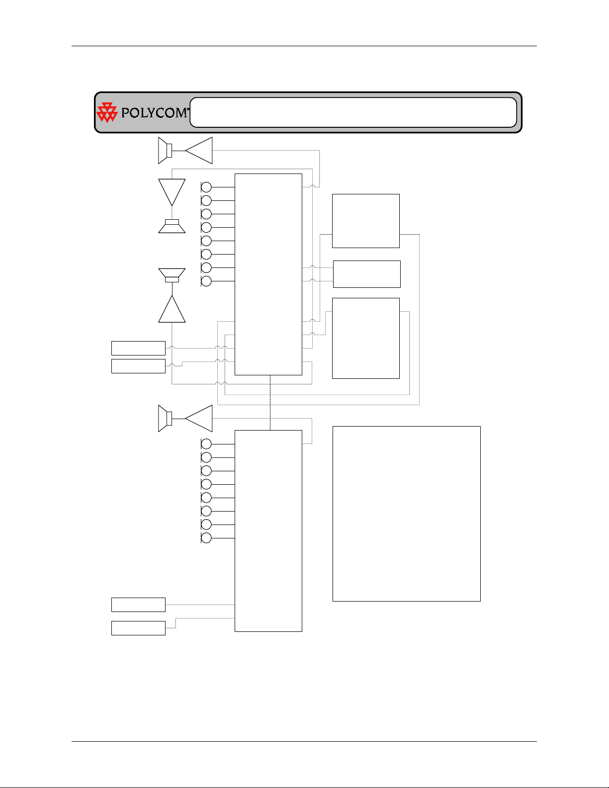
Factory Preset 0:
8 mics per zone
y
y Inputs 1-8 direct out
y Inputs A-D mix minus to
Outputs A-D for codec,
Phone Add, room audio
and/or program audio
Vortex Factory Preset 0: Default
Mono Program Audio
In 1
In 2
In 3
In 4
In 5
In 6
In 7
In 8
In A
In B
In C
In D
Vortex
®
Out 1
Out 2
Out 3
Out 4
Out 5
Out 6
Out 7
Out 8
Out A
Out B
Out C
Out D
Video
CODEC
Line In Line Out
From AEC
From Rem.
EF200
Record
PRESETS
To AEC
To Rem.
Phone
Vortex
®
Applications and Presets Guide 10 Technical Support: (800) 932-2774
Page 13

Factory Preset 1:
y
8 mics per zone
y
Inputs 1-8 direct out
y
Inputs A, B mix minus to
Outputs A, B for codec
and Phone Add
y
Inputs and Outputs C, D
stereo room audio and/or
program audio
Left Program
Audio
Right Program
Audio
In 1
In 2
In 3
In 4
In 5
In 6
In 7
In 8
In A
In B
In C
In D
Vortex
PRESETS
Out 1
Out 2
Out 3
Out 4
Out 5
Out 6
Out 7
Out 8
®
Out A
Out B
Out C
Out D
Video
CODEC
Line In Line Out
From AEC
From Rem.
To AEC
To Rem.
EF200
Phone
© Polycom, Inc. 11 Vortex
®
Applications and Preset s Guide
Page 14

Vortex Factory Preset 2: Split, Mono
PRESETS
Factory Preset 2:
y 2 Rooms
y 4 mics per room
y Outputs 1 and 5 room
audio
y Inputs A & B, C & D mix
minus to Outputs A & B,
C & D for codec and
Phone Add per room
Video
CODEC
Line In Line Out
From AEC
To AEC
From Rem.
To Rem.
In 1
In 2
In 3
In 4
In 5
In 6
In 7
In 8
In A
In B
In C
In D
Vortex
Out 1
Out 2
Out 3
Out 4
Out 5
Out 6
Out 7
Out 8
®
Out A
Out B
Out C
Out D
EF200
Phone
Video
CODEC
Line In Line Out
From AEC
To AEC
From Rem.
To Rem.
EF200
Phone
Vortex
®
Applications and Presets Guide 12 Technical Support: (800) 932-2774
Page 15

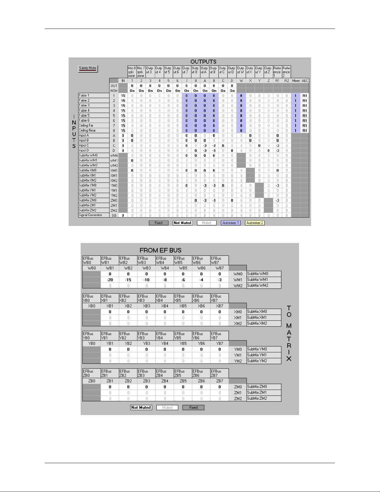
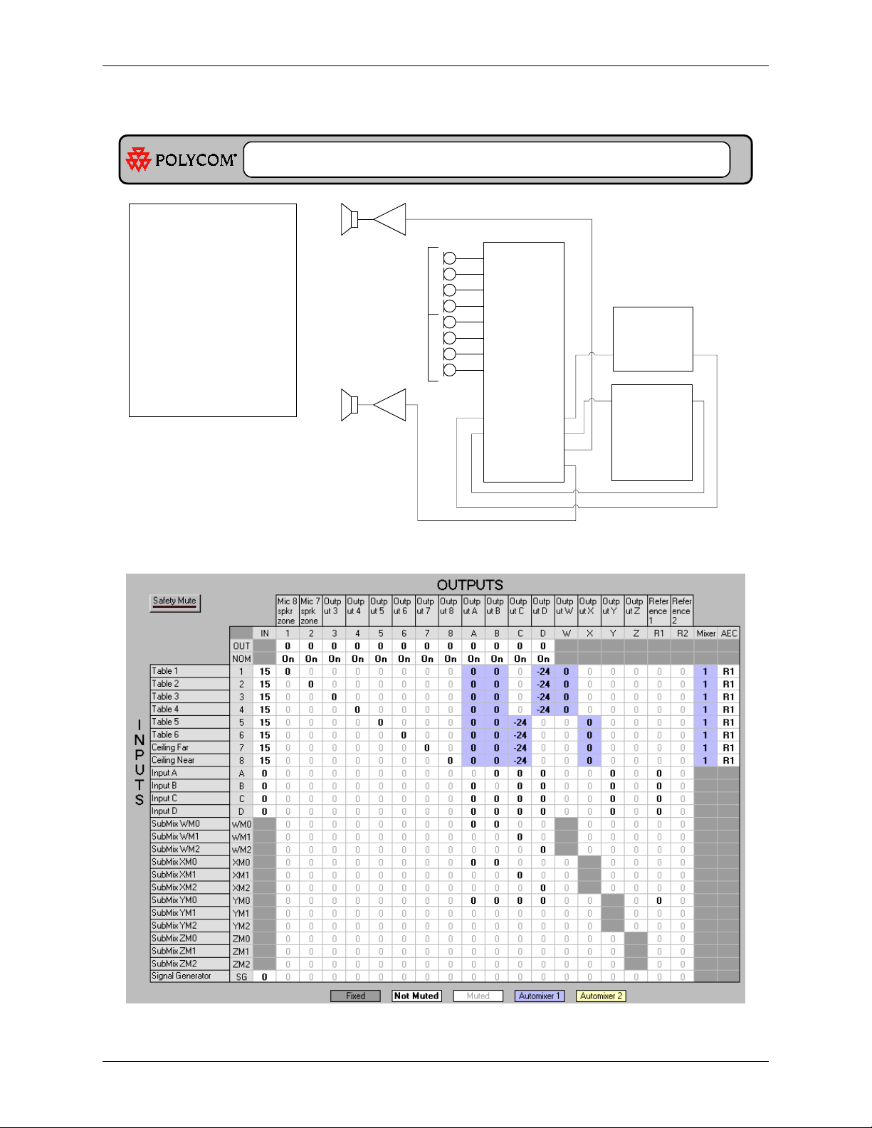
Vortex Factory Preset 4: 8 mics/Zone
PRESETS
Program Audio
In 1
In 2
In 3
In 4
In 5
In 6
In 7
In 8
In A
In B
In C
In D
In 1
In 2
In 3
In 4
In 5
In 6
In 7
In 8
In A
In B
In C
In D
Vortex
Vortex
®
®
Out 1
Out 2
Out 3
Out 4
Out 5
Out 6
Out 7
Out 8
Out A
Out B
Out C
Out D
Out 1
Out 2
Out 3
Out 4
Out 5
Out 6
Out 7
Out 8
Out A
Out B
Out C
Out D
Video
CODEC
Line In Line Out
From AEC
From Rem.
To AEC
To Rem.
EF200
Phone
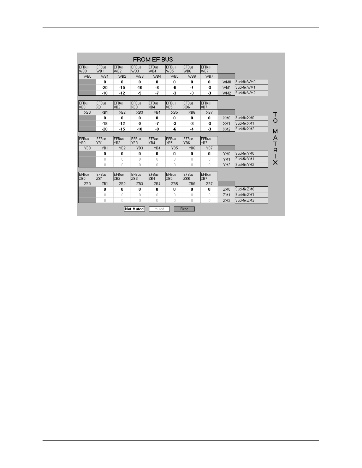
Factory Preset 4:
y
8 mics per Zone
y
Output D room audio per
Zone
y
Inputs A & B mix minus
to Outputs A & B for
codec & Phone Add
Submatrix
y
WM0: Mix of all mics for
codec and Phone Add
y
WM1: Zone room audio
with other zones' mics
reinforced
y
YM0: Program audio and
remote end audio
© Polycom, Inc. 13 Vortex
®
Applications and Preset s Guide
Page 16
PRESETS
The Submatrix assumes that Vortex 01 is the next closest zone, Vortex 02 is the next one, etc., and Vortex 07 is the
farthest zone (reinforced at the highest level).
®
Vortex
Applications and Presets Guide 14 Technical Support: (800) 932-2774
Page 17
Zone Speaker
PRESETS
Left Program
Audio
Right Program
Audio
Zone Speaker
Left Program
Audio
Right Program
Audio
Front Program
Audio Speakers
In 1
In 2
In 3
In 4
In 5
In 6
In 7
In 8
In A
In B
In C
In D
In 1
In 2
In 3
In 4
In 5
In 6
In 7
In 8
In A
In B
In C
In D
Vortex
Vortex
®
®
Out 1
Out 2
Out 3
Out 4
Out 5
Out 6
Out 7
Out 8
Out A
Out B
Out C
Out D
Out 1
Out 2
Out 3
Out 4
Out 5
Out 6
Out 7
Out 8
Out A
Out B
Out C
Out D
Video
CODEC
Line In Line Out
Stereo
Recorder
From AEC
From Rem.
To AEC
To Rem.
EF200
Phone
Factory Preset 5:
y
8 mics per Zone
y
Output 1 zone speaker
y
Outputs 7 & 8 stereo record
y
Outputs C & D stereo program
audio
y
Inputs A & B mix minus to
Outputs A & B for codec and
phone add
Submatrix
y
WM0: Mix of mics at unity gain
y
WM1: Reinforced mix of other
mics
y
XM0: Codec and Phone Add
y
YM0, ZM0: Stereo program
audio
© Polycom, Inc. 15 Vortex
®
Applications and Preset s Guide
Page 18
PRESETS
The Submatrix assumes that Vortex 01 is the next closest zone, Vortex 02 is the next one, etc., and Vortex 07 is the
farthest zone (reinforced at the highest level).
®
Vortex
Applications and Presets Guide 16 Technical Support: (800) 932-2774
Page 19
Vortex Factory Preset 6: 4 mics/Zone
PRESETS
Factory Preset 6:
4 mics per Zone
y
Output C & D room audio per
y
Zone
Inputs A & B mix minus to
y
Outputs A & B for codec &
Phone Add
Submatrix
WM0, XM0: Mix of mics at
y
unity gain for codec and
Phone Add
WM1, WM2, XM1, XM2: Zone
y
room audio with other zones'
mics reinforced
YM0: Program audio and
y
remote end audio
Zone 1
Zone 2
Zone 1
Zone 2
In 1
In 2
In 3
In 4
In 5
In 6
In 7
In 8
In A
In B
In C
In D
Vortex
®
Out 1
Out 2
Out 3
Out 4
Out 5
Out 6
Out 7
Out 8
Out A
Out B
Out C
Out D
Video
CODEC
Line In Line Out
From AEC
From Rem.
To AEC
To Rem.
EF200
Phone
© Polycom, Inc. 17 Vortex
®
Applications and Preset s Guide
Page 20
PRESETS
The Submatrix assumes that Vortex 01 is the next closest zone, Vortex 02 is the next one, etc., and Vortex 07 is the
farthest zone (reinforced at the highest level).
Presets 3, 7-12 Reserved.
Preset 13 Passthrough Mic.
1-8 set to Mic level. Everything else is disabled.
Preset 14 Passthrough Line.
Inputs 1-8 set to Line level. Everything else is disabled.
Preset 15 Blank Slate.
Passthrough mode (Inputs 1-8, A-D are direct out) with Inputs
Passthrough mode (Inputs 1-8, A-D are direct out) with
All crosspoints muted. Everything disabled.
Vortex
®
Applications and Presets Guide 18 Technical Support: (800) 932-2774
 Loading...