

Page 1

E
CHOFREE
EF200
™
P
HONE
U
SER
A
M
DD
ANUAL
Page 2

Copyright © 1999 ASPI Digital. All rights reserved. Printed in the United States of America.
Because of technical progress, specifications are subject to change without notice.
EchoFree is a trademark and ASPI is a registered trademark of ASPI Digital.
ASPI Digital - The Sound of DSP
1720 Peachtree Street NW, Suite 220
Atlanta, GA 30309-2439
(404) 892-3200
www.echofree.com
Technical Support:
(404) 892-3200
help@aspi.com
EF200UM-0100-99
Page 3

EF200 U
SER MANUAL
Introduction.... ........ .............. .................... .............. ............. .............. ...........2
Product Features.......................... ............................................ ........ ........... ........... 3
Insta l lation.................. .............. .............. .................... ............. .............. .......4
Preparing for Installation....................................................................................... 4
EF200 Front and Rear Panels................................................................................ 5
Setting the DIP Switches......................................................................................... 7
Connecting the EF 200 to Other Equipment........ ............................... .......... ..........9
Configuring the Non-Volatile Memory................................................................... 10
Calibrating the EF200 Audio Signal Levels........................................................... 12
Connecting Multiple EF200s................................... .......... .................... ................. 13
Mounting the EF200..................... ............................................ .............................. 14
Using the Logic In/Out Port ................................................................................... 15
Operating the EF200 ...................................................................................17
Using the EF200 Without RS-232 Control........................................... ..................17
Using the EF200 with RS-232 Control................................................................... 17
Troubleshooting...........................................................................................19
Residual Echo......................................................................................................... 19
Can’t Receive Calls or Dial Out............................................................................. 19
Can’t Get Caller ID Information............................................................................ 20
Remote Control Problems....................................................................................... 20
Contacting Technical Support ................................................................................ 21
Technical Specifications ..............................................................................22
Compliance............................................................................................................. 22
Warran ty Informa ti o n ..... .............. ................................. .......................... ..24
EF200 Command Set Reference.................................................................26
Command Syntax........................ .................... ..................... .......... .................... ..... 26
EF200 Block Diagram ................................................ .................................69
Connector Pinouts........................................................................................70
ASPI Digital, Copyright 1998 1
Page 4

I
NTRODUCTION
EF200 U
SER MANUAL
Congratulations!
About This Manual
Product Description
Congratulations on your purchase of the EchoFree™ EF200 Phone Add. By choosing ASPI Digital’s EchoFree products, you are investing in cutting edge DSP technology that will help provide the best possibl e audio quality for your syste m.
This manual expla in s how to insta ll, co nfigure, and cal ibrate the EF200 i n any syste m
that needs a two-wire to four-wi r e interface. It also provides in formation about operating and troubleshooting the EF200.
The EchoFree™ EF200 Phone Add provides a full duplex interface between a fourwire audio syste m and a two-wire telephone line. It al lows a telephone caller to be
brought in to any four-wire audio system, such as a distance learning or videoconferencing system. The EF200 is similar to a digital hybrid, but with many more fea tures
and capabilities.
The primary function of the EF200 is the line echo canceller (LEC), which digitally
eliminates reflections from the telephone hybrid. The LEC algorithm features
extremel y fas t adaptation and exc ellent full duplex operation. This allows n atural
communication wit hout half- duplex be havior or resi dual echo. The LEC algorit hm is
G.165 and G.168 compl iant, which ensure s relia ble, pro ven performa nce. Be cause of
its rapid adapta tion, the EF200 requires no training noise. This means that callers
don’t get blasted by white noise at the beginning of the connection.
Unlike other phone adds , the EF200 also includes an advanced noise suppress ion
algorithm, which improves the signal to noise ratio of incoming tele phone signals by
up to 10 dB, without adding distortion or “musical noise” to the speech signal. This
greatly improves overall speech quality for all par ticipants when callers are in a noisy
environment or are us ing a noisy connecti on such as a cellular phone .
Automatic gain c ontrol ensures consistent audio leve ls , compensating for diffe rences
between different lines and handsets . This means users don’t have to change volum e
levels when they s w itch from local to long distance calls. Automatic gain control,
line echo cancellation, and noise suppression all work together to ensure consist ently
high audio quality every time you make a call.
The EF200’s telep hony features enhance its usefulness in integra ted systems. The
DTMF dialing and Cal l P r ogress capabilities help make dialing intuitive, through a
remote control device. The ring and entry tone generation capability allows users to
hear when someone is “ringing” the EF200, even if an analog handset is not connected to the system. The DTMF detection feature allows integrators to add touc h
tone remo te control capability to th eir system s.
These features make the EF200 the most advanced device of its kind. Cutting edge
DSP technology gives it the best sound quality available. The wi de range of features
and controllability make the EF200 extremely flexible, while providing a straightforward user interface for simple installations.
Warranty
Registration
2 Copyright © 1998, All Rights Reserved
Please take a moment to fill out and return your warranty registra tion card. This
information will help us to provide you with bette r cus tom er support.
Page 5

I
NTRODUCTION
P
RODUCT FEATURES
• Easily connects to an Acoustic Echo Canceller (AEC) (such as the ASPI Digital
EF400) or other four-wire system to add phone calls to co nferences.
• ASPI’s proprietary noise reduction algorithm reduce s static and hiss, to make
conference more intelligible and comfortable.
• Built-in DTMF dialer and detector.
• Built-in Caller ID feature allows conference moderator to see who is calling in.
• User-set “entry” and “exit” tones give you the option to hear a pleasant tone
when callers enter or leave t h e conference.
• Connection is quiet, non distrac ting.
• Automatic gain control on both the receive a nd transmit audio paths.
• Complete RS-232 control for operation through your room controller, including
dialing out to a remote office.
• “Privacy” mode for private conversations with the people in the room, the party
on the telephone, or the remote 4-wire party.
• Up to 32 EF200s can be linked together to form a simple conference bridge.
• Diagnostic information is available to syst em integrators and other personnel vi a
the EF200’s RS-232 port, permitting remote trouble-shooting if necessary.
• LED bargraphs on the front panel, which are useful for visual indication of audio
levels and proper s ys tem operation.
ASPI Digital -
The Sound of DSP
3
Page 6

I
NSTALLATION
The installation process for the EF200 consists of the following steps:
1. Prepare for installation (below).
2. Configure the DIP switches on the rear panel (page 7).
3. Connect the EF200 to other equipment (page 9).
4. Configure the EF200’s non-volatile memory (if using RS-232) (page 10).
5. Calibrate the EF200 to other equipment in the system (page 12).
6. Mount the EF200 in a rack or on a tabletop (page 14).
REPARING FOR INSTALLATIO N
P
Reading the entire manual (or at least the in st allation section) before beginning the
installation process will help you be more prepared for installation. Also, please
make sure you have t he correct equipment (outlined below) before you begin installation.
EF200 U
SER MANUAL
What’s Included
What’s Not Included
The EF200 product packa ge includes the following items:
• EF200 User Manual (this manual)
• EF200 Phone Add
• External Power Supply
• Warranty Registration Card
The followin g equipm ent i s not inc luded wi th t he EF200 produ ct pac kage, but m ay be
necessary to create a completely functional system:
• Microphone(s)
• Loudspeaker(s)
• Audio amplifie r (or am plified loudspea ker)
• EchoFree EF400 Acoustic Echo Canceller
• Audio cables
• Videoconferencing CODEC or other four-wire interface (optional)
• Tape recorder or VCR (optional)
• RS200 Rack Mount sh elf (included with purchase of EF200 and EF400 toge ther)
• RS-232 remote control device (optional)
4 Copyright © 1998, All Rights Reserved
Page 7
I
NSTALLATION
EF200 F
POWER
)
FF
O
TO
ET
(S
ESERVED
R
N
O
O
FF
RONT AND REAR PANELS
TO PHONE FROM PHONE
LEVEL LEVEL
PRIVACY ON
21 3 4 5 6 7 8 9 1110
13 15 17
)
FF
O
TO
ET
(S
ESERVED
AGC
R
PROM
E
UPPRESSION
ID 4
S
VERRIDE
OISE
EVICE
D
O
N
ID 3
EVICE
D
ID 2
EVICE
D
ID 1
EVICE
D
ID 0
EVICE
D
REMOTE CONTROLREMOTE CONTROL
RS-232
LOGIC IN/OUT
ASPI BUS
IN
ASPI BUS
OUT
TO PHONE
TO LINE
PRIVACY REMOTE PHONE
REMOTE CONNECT
PHONE CONNECT
EF400
INTERFACE
FROM
AECTOAEC
FROM
REMOTETOREMOTE
T H E
S O U N D O F D S
EchoFree
EF200
5, 15 VDC 5, 15 VDC
POWER
P
TM
12
14 16 18 19 20 21 22 23 24
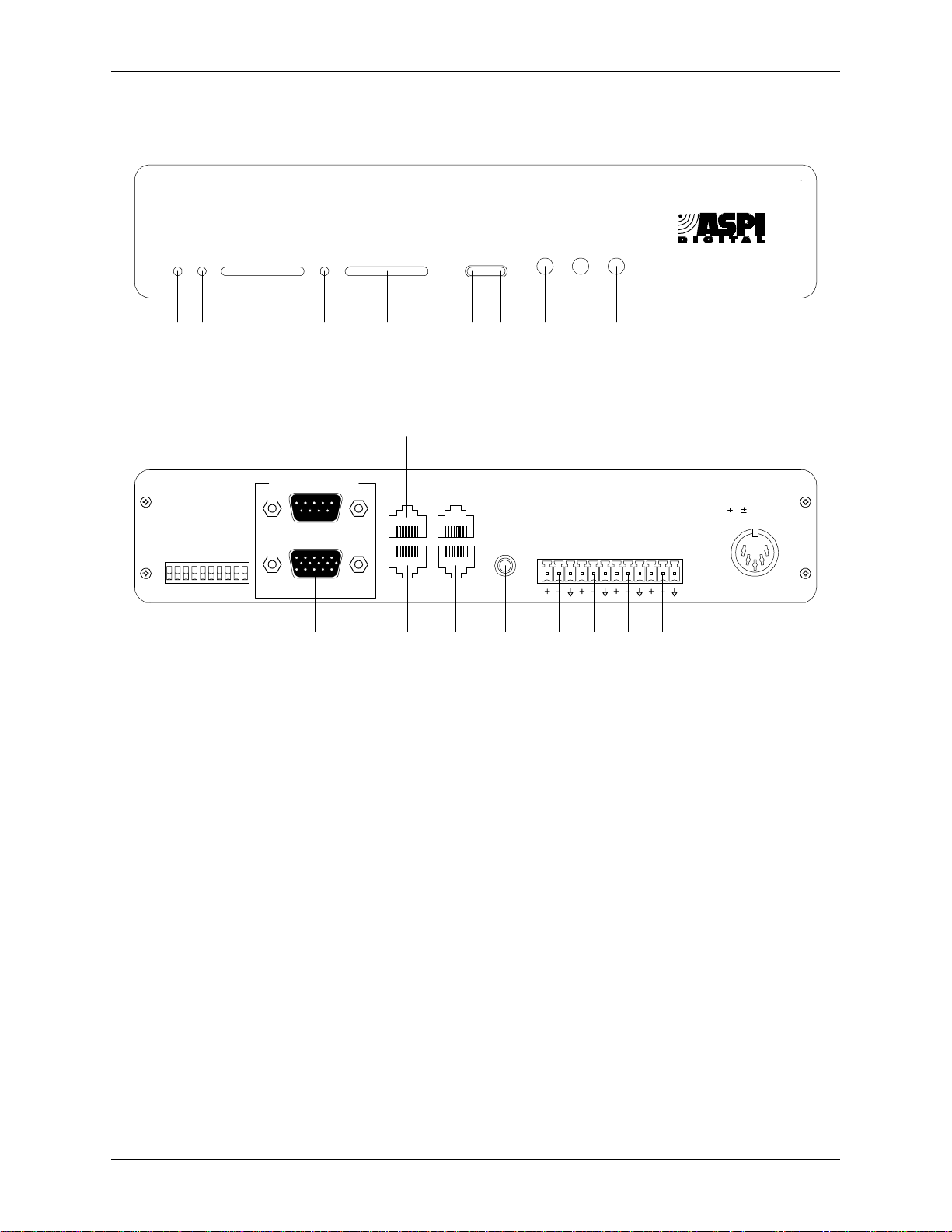
Figure 1. EF200 Front and Rear Panels
OWER INDICATOR
1. P
ROM REMOTE GAIN TRIMPOT
2. F
the F
O PHONE LEVEL INDICATOR
3. T
line.
O REMOTE GAIN TRIMPOT
4. T
O REMOTE
T
ROM PHONE LEVEL INDICATOR
5. F
telephone line.
RIVACY ON INDICATOR
6. P
EMOTE CONNECT INDICATOR
7. R
nected.
HONE CONNECT INDICATOR
8. P
is connected.
RIVACY BUTTON
9. P
EMOTE BUTTON
10. R
HONE BUTTON
11. P
12. DIP S
13. RS-232 R
control devic e, such as a touch panel or personal computer COM port.
OGIC IN/OUT PORT
14. L
. When the LED is green, power is on.
ROM REMOTE
channel.
channe l.
. Push this button to turn pri vac y mod e on or off.
. Push this button to connect or disconnect remo te audio.
. Push this button to pic k up o r h ang up the telephone line.
WITCHES
.
EMOTE CONTROL PORT
. Connect this to logic switches for optional remote control.
. This adjusts the gain on the signal coming in on
. Displays the signal level going to the telephone
. This adjusts the gain on the s ignal going out on the
. Displ a y s the sig na l level co m i ng in from th e
. This LED is blue when privacy mode is on.
. This LED is green when the remote audio is con-
. This LED is green when the EF200 2-wire audio
. Connect this to an optional RS-232 remote
ASPI Digital -
The Sound of DSP
5
Page 8

EF200 U
SER MANUAL
15. ASPI BUS IN. Connects to the ASPI BUS OUT of another ASPI Digital device or
an ASPI Bus terminator, if the ASPI Bus is in use.
16. ASPI B
US OUT
. Connects to the ASPI BUS IN of another ASPI Digital device or
an ASPI Bus terminator, if the ASPI Bus is in use.
O PHONE
17. T
O LINE
18. T
19. EF400 I
. Connects to an analog telephone handset for manual dialing.
. Connects to the telephone line from th e wall socket.
NTERFACE
. Connects to an EF400 for remote control of the EF400 (not
currently implemented).
ROM
20. F
21. T
22. F
AEC. Connects to the remote output of the AEC.
O
AEC. Connects to the remote input of the AEC.
ROM REMOTE
. Connects to the audi o output of a CODEC or other 4-wire
device.
O REMOTE
23. T
OWER SUPPLY INPUT
24. P
. Connects to the audio input of a CODEC or other 4-wire device.
. Connects to the external power supply provided with the
EF200.
6 Copyright © 1998, All Rights Reserved
Page 9

I
NSTALLATION
S
ETTING THE
DIP S
Note
Switches 1 & 2:
Reserved
Switch 3: AGC
Enable
Switch 4: Noise
Suppression Enable
WITCHES
Locate the 10 position DIP switch on the left side of the EF200 rear panel. For the
purpose of this dis cus sion, the switches are num bered one through ten, from left to
right. The follo wing ins tructions expla in how to set each switch.
Changing the DIP switches will have no effec t until the EF200 is reset. Each time
you change the set ting of the DIP switches, you must turn the EF200 off and back on
for the changes to take effect.
Switches 1 and 2 are reserved, and should always be set to the off position.
When this switch is on, automat ic gain control is enabled on the telephone input signal when the EF200 is powered up. After the EF200 is powered up, the automatic
gain control s tatus may change if commands are sent to turn it off. Also, this switc h
may be disabled, dep ending on the settings of switch 5 (see below). The default set ting fo r thi s sw itch is of f.
This switch con trols whether noise suppression is applied to the telephone input signal when the EF200 is powered up. After the EF200 is powered up, the noise su ppression statu s may cha nge if commands ar e sent to tu rn it on or off. This swit ch may
be disabled, dependi ng on t he setti ngs of s wit ch 5 (see be low). The de fault s etti ng for
this switch is off.
Switch 5: Override
EPROM
Switches 6-10:
Device ID
When this switch is off, the non-volatile memory settings for automatic gain control
and noise suppression take precedence over the DIP switch settings. When it is on,
the DIP switch settings take prece denc e over the software settings. In other words, if
the Override EPROM switc h is off, the settings of switc hes 3 and 4 have no effect.
See the section about non-volatile memory configuration for more information about
internal aut omatic ga in contro l and noise suppre ssion s etti ngs. The default sett ing for
this switch is off.
These switches set the Device ID number for the EF200. The ID can be any number
from 0 to 31. It is a five bit binary number , with the least significant bit on switch 10.
Table 1 lists the DIP switch positions neces sary to set each Device I D number from 0
to 31.
The Device ID is the same ID that is used with the EF200 Command Set. The EF200
will respond onl y to comma nds that are sent with the same Devic e ID as the one set
on its switches. If you set the Device ID to one that doesn’t agree with your remote
control commands, the remote control will no longer affec t that particular EF200.
If you are not us ing a remote cont rol de vice ( via RS-232 or the ASPI B us), t he Devic e
ID settings do no t matter. The default Devi ce ID is 0.
ASPI Digital -
The Sound of DSP
7
Page 10

EF200 U
Table 1: DIP Switch Posit ions for EF200 Device IDs (Blank spaces mean switch is off)
SER MANUAL
Device ID Switch 6
(Device ID 4)
0 (default)
1 ON
2ON
3ONON
4ON
5ONON
6ONON
7 ONONON
8ON
9ON ON
10 ON ON
11 ON ON ON
12 ON ON
13 ON ON ON
14 ON ON ON
15 ON ON ON ON
16 ON
17 ON ON
18 ON ON
19 ON ON ON
20 ON ON
21 ON ON ON
22 ON ON ON
23 ON ON ON ON
24 ON ON
25 ON ON ON
26 ON ON ON
27 ON ON ON ON
28 ON ON ON
29 ON ON ON ON
30 ON ON ON ON
31 ON ON ON ON ON
Switch 7
(Device ID 3)
Switch 8
(Device ID 2)
Switch 9
(Device ID 1)
Switch 10
(Device ID 0)
8 Copyright © 1998, All Rights Reserved
Page 11
I
NSTALLATION
C
ONNECTING THE
Telephone and
Audio Connections
)
)
FF
FF
O
O
TO
TO
ET
ET
VERRIDE
(S
(S
UPPRESSION
O
ID 4
ID 3
ID 2
ID 1
PROM
E
EVICE
D
EVICE
D
EVICE
D
EVICE
D
ID 0
EVICE
D
S
OISE
ESERVED
ESERVED
R
R
N
AGC
O
N
O
FF
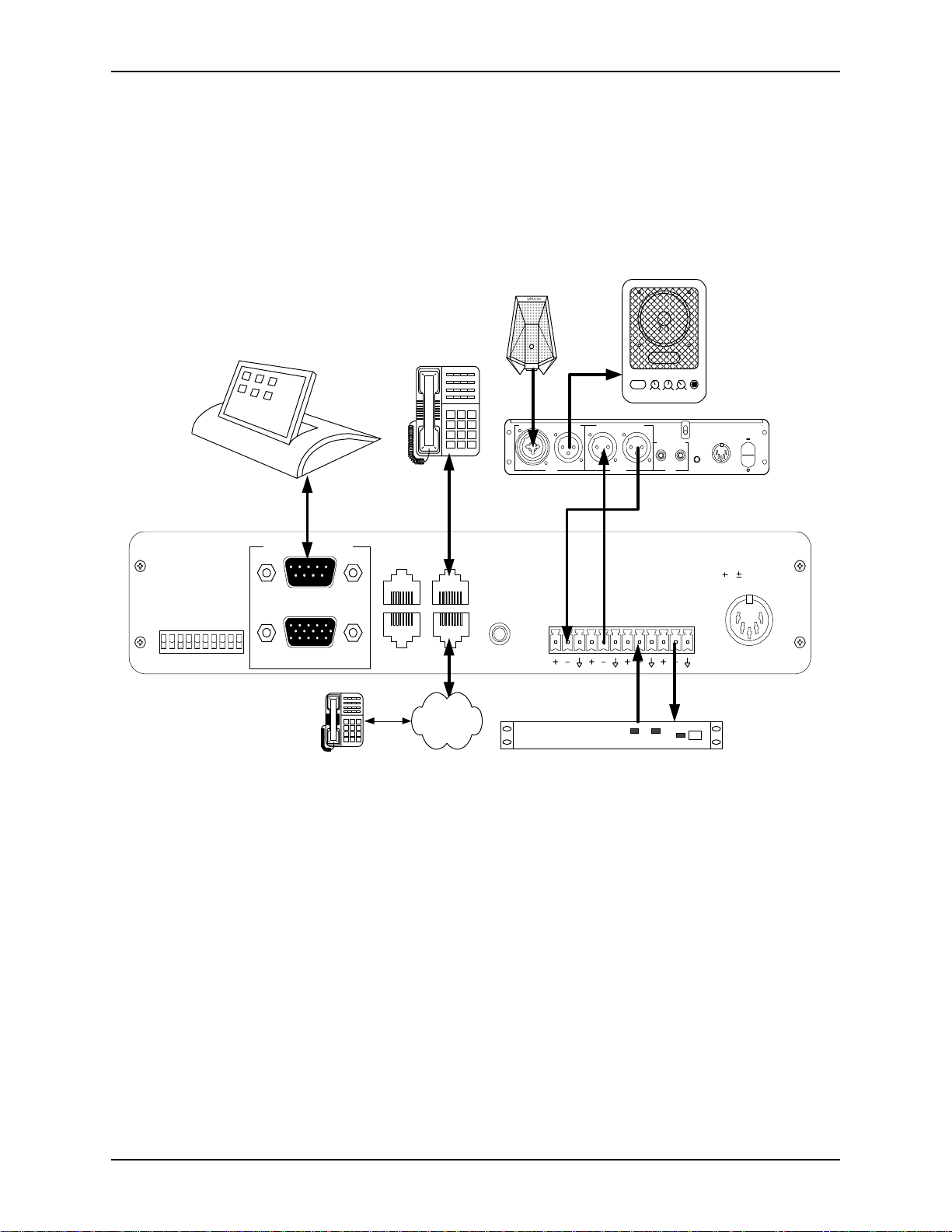
EF200 TO O
THER EQUIPMENT
The connections des cribed below are also shown in Figure 2.
The EF200 will typically be connected to other equipment as shown below.
microphone
POWER LOW HIGH VOLUMEMIC
POWERED SPEAKER
1
2
3
4
5
REMOTE CONTROL
RS-232
LOGIC IN/OUT
ASPI BUS
IN
ASPI BUS
OUT
7
8
*
0
TO PHONE
TO LINE
6
9
#
EF400
INTERFACE
MIC I
NPUTSPEAKER OUTPUT
1(875,.
R
OOM
FROM
AECTOAEC
I
NPUT
O
UTPUT
R
EMOTE
FROM
REMOTETOREMOTE
P
LAYRECORD
T
APE
M
UTE
R
OOM
I
NPUT
+5,+/-15
VDC
5, 15 VDC
ON/O
FF
Figure 2. Typical EF200 Connections
• Connect the T
• Connect the EF200’s T
• Connect the T
• Connect the F
• Connect the T
• Connect the F
• If RS-232 remote co ntrol is desired, con nect the RS-232 R
• Connect the external power supply to the P
ASPI Digital -
The Sound of DSP
PSTN
O PHONE
CODEC/hybrid
jack of the E F 200 to an analog telephone hands et using a
TX RX
standard telephone cable.
O LINE
jack to the telephone line in your wall, us ing a
standard (RJ11) modular telephone cable.
O
AEC jack to the input of the local room audio system. This may
be the input to an AEC, such as the R
ROM
AEC jack to the outpu t of the local room audio system. This
EMOTE INPUT
may be the output of an AEC, like the EF400’s R
O REMOTE
jack of the EF200 to the input of a vi deo CODEC or
of the EF400.
EMOTE OUTPUT
.
other four-wire transmission interface.
ROM REMOTE
jack of the EF 200 to th e ou tput of a vi deo CODEC or
other four-wire transmission interface.
EMOTE CONTROL
port
of the EF200 to a remote control device, such as an RS-232 inte rface to a touch
panel or a COM port on a personal computer.
OWER SUPPLY INPUT
jack of the
9
Page 12

EF200.
EF200 U
SER MANUAL
Note
Note
Note
Caution!
C
ONFIGURING THE NON-VOLATILE MEMORY
Note
In order to add a phone call to a c onnection, either (or both) the AEC or R
nectors of the EF200 must be connected to other equipment.
To dial a number, the EF200 needs either the RS-232 port or the analog telephone
handset to be connected. Only one of these is nec es sary to make calls. Calls can be
received using only the front panel buttons. The RS-232 port may be needed to configure power-on defaults in the non-volatile memory during the installation process.
The TO L
connectors will still fit snugly.
Do not connect the telephone handset or telephone line to the ASPI Bus.
The EF200 has a non-volatile memory which can store use r cus tom izeable default
settings for the EF200’s features. When the EF200 i s power ed on, it will read the
non-volatile memory and initialize to the se settings. Once the unit is running, the settings may be changed by commands or logic port switches. These changes won’t
affect the non-volatile memory unless they are saved using the SAVENV command.
The EF200 must be turned on and connected to the RS-232 remote control device in
order to configure the non-volatile memory.
If the O
noise suppression settings in the non -volatile memory will have no ef fect. In that
case, the EF200 will in itialize to the automatic gain control and noise suppression settings on the DIP swit che s.
INE
and TO P
VERRIDE EPROM
HONE
EMOTE
con-
jacks are wider than RJ11 telephone jacks, but the RJ11
switch is turned on, changing the automatic gain cont rol and
10 Copyright © 1998, All Rights Reserved
Page 13

I
NSTALLATION
Making Changes
Set each of the parameters to the desired value s by sending RS-232 commands to the
unit. Table 2 list s the parameters that are stored in the non-volatil e memo ry, and the
RS-232 commands that configure them.
Table 2: Non-volatile Memory Parameters
Command EF200 Initialization Parameter Default
AA Auto answer ena ble/disabl e 0 (off)
ACKMOD Acknowledgment mode enable/disable 1 (on)
AGC Automatic gain control enable/disable 1 (on)
AH Auto hangup mode enable/disable 0 (off)
CALLP Call progress enable/disable 0 (off)
CID Call er ID en able/d i sable 0 (off)
DTMF DTMF decoding enable/disable 0 (off)
DTMFC Enable/disable DTMF clamping 0 (off)
ERROR Error reporting enable/disable 1 (on)
GAINA From phone gain 3 (dB)
GAINP To phone gain 0 (dB)
LEC Enable/disable line echo canceller 1 (on)
LOCKFP Lock/unlock front panel buttons 0 (off)
NS Noise suppression enable/disable 1 (on)
NSL Noise suppression level 10 (dB)
RING Enable/d isable ring messages 0 (off)
TONEE Enable/dis able entry and exit tones 1 (on)
TONER Enable/disable ring tones 1 (on)
Saving Changes
ASPI Digital -
The Sound of DSP
Note
Once the desired parameters have been set on the EF200, s ave them to the non-volatile me mory by s en d ing the SAVENV command. The EF200 will be initialized with
these settings every time the uni t is powered on. You can save to the non-volatile
memory up to 10,000 times.
Saving th e parameters takes a few seconds, and should not be done during a conversation. Saving parame ters duri ng a conve rsation may ca use gaps in the audio, while the
EF200 writes to the non-volatile memory.
11
Page 14

EF200 U
SER MANUAL
C
ALIBRATING THE
Calibrating the AEC
Warning!
Calibrating the
ROM REMOTE
F
Signal
EF200 A
The EF200 is designed to interface with a wide range of signal l evels, so that it ca n be
compatible with most equipment. The expected levels for input and output should be
set on the EF200 to matc h the levels of the equipm ent to which it is connected. The
following procedure should be followed to match these levels.
If you are connecting an ASPI Digital EF400 Acoustic Echo Canceller to the AEC
jacks of the EF200, the calibration proce ss is quite easy. Open the EF400, and turn
the remote output pot ( R25) fully counter-clockwise to -20 dBu. Turn the remote
input pot (R24) fully clockwise to -20 dBu. The EF200 is desi gned to work with the
EF400 when it is set to these levels.
If other equip me nt is connected to the F
capable of interfacing with -20 dBu signals.
The pots on the EF400 are sin gle turn pots only. Do not try to turn them to o f ar.
The F
locate d just to the left of the T
is from -20 dBu (nominal) to +4 dBu (nominal). To calibrate th is input, you need to
have someone on the remote end talk so that you can verify their speech level on the
O PHONE LEVEL INDICATOR
T
1. Turn on the EF200, as well as the ro om audio sys tem (inc ludi ng the AEC) so th at
2. Have the person on t he remote end sp eak in a nor mal voice whi le the re is no loca l
3. Adjust the F
UDIO SIGNAL LEVELS
ROM
AEC and TO AEC jacks, it shoul d be
ROM REMOTE
you can he ar the speech o n the remote end.
audio input through the AEC.
remote end frequently illuminate the first ye llow LED on the T
NDICATOR
I
pot clockwise will increase the level, and turning it counterclockwise will
decrease the level. This is a five-turn trimpot.
signal level is adjusted using the F
O PHONE LEVEL INDICATOR
.
ROM REMOTE GAIN TRIMPOT
, and occasiona lly flicker the second yellow LED. Turning the tr im-
until normal speech levels from the
ROM REMOTE GAIN TRIMPOT
. The range of adjustment
O PHONE LEVEL
,
Calibrating the TO
EMOTE
R
Signal
Note
Verifying
Calibration
12 Copyright © 1998, All Rights Reserved
The TO R
O REMOTE
T
eral this wou ld be abou t the same as th e nomin al input lev el. The ran ge of a djust ment
is from -20 dBu (nomina l) to +4 dBu (nomi nal). Adjust t his t rimpot unti l the C ODEC
or other 4-wire equipment is receiving the co rrec t level. This is also a five-turn trimpot.
The F
the leve l going to the T
EMOTE GAIN TRIMPOT
R
Give the EF200 a test run, us ing both the AEC and remote connecti ons, if possible.
During normal conversation, the T
EVEL INDICATOR
L
occasionall y flicker the second. Level s that are much too high or too low may pre-
EMOTE GAIN TRIMPOT
signal is appropria te for the equipment to which it is c onnected. In gen-
ROM PHONE LEVEL INDICATOR
O REMOTE
, the level shown on the meter will not change.
should show levels that regularly hit the first yellow LED, and
should be calibrated so that the outpu t level of the
shows the level received from the telephone, not
jack. When you change the gain on the TO
O PHONE LEVEL INDICATOR
and F
ROM PHONE
Page 15
I
NSTALLATION
vent the EF200 or othe r equipment from performing as desi gned, and audio quality
may suffer.
When connected to an EF400, the EF200’s T
O PHONE LEVEL INDICATOR
should
show the same level as the EF400’s remote level indic ator: correct setting of this
level is vi ta l to the corre c t o perati on of th e EF400 .
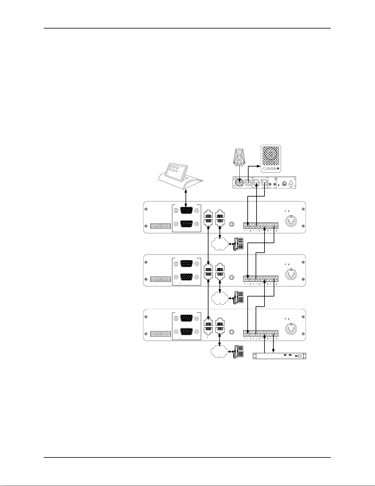
C
ONNECTING MULTIPLE
EF200
S
Multiple EF200s can be easily connect ed together to allow multiple callers to be
brought into the system. When the audio signa ls are connected acc ording to the following directions, the EF200 takes care of the necessary mixing functionality. The
ASPI Bus allows mult iple devices to be controlled by a single RS-232 connection.
microphone
POWER LOW HIGHVOLUME MIC
POWERED SPEAKER
I
NPUT
MIC I
NPUTSPEAKER OUTPUT
1(875,.
OOM
R
VERRIDE
O
PROM
E
REMOTE CONTROL
ID 4
ID 3
EVICE
EVICE
D
D
RS-232
ID 2
ID 1
ID 0
EVICE
EVICE
EVICE
D
D
D
LOGIC IN/OUT
)
)
FF
FF
O
O
TO
TO
ET
ET
(S
(S
UPPRESSION
S
OISE
ESERVED
ESERVED
R
N
R
AGC
N
O
FF
O
ASPI BUS
IN
ASPI BUS
OUT
TO PHONE
TO LINE
EF400
INTERFACE
PSTN
VERRIDE
O
PROM
E
REMOTE CONTROL
ID 4
ID 3
EVICE
EVICE
D
D
RS-232
ID 2
ID 1
ID 0
EVICE
EVICE
EVICE
D
D
D
LOGIC IN/OUT
)
)
FF
FF
O
O
TO
TO
ET
ET
(S
(S
UPPRESSION
S
OISE
ESERVED
ESERVED
R
N
R
AGC
O
N
O
FF
ASPI BUS
IN
ASPI BUS
OUT
TO PHONE
TO LINE
EF400
INTERFACE
FROM
AECTOAEC
FROM
AECTOAEC
O
UTPUT
EMOTETAPE
R
FROM
REMOTETOREMOTE
FROM
REMOTETOREMOTE
P
LAYRECORD
+5,+/-15
ON/O
FF
VDC
M
UTE
R
OOM
I
NPUT
5, 15 VDC
5, 15 VDC
Connecting the AEC
and CODEC
ASPI Digital -
The Sound of DSP
PSTN
ASPI BUS
IN
ASPI BUS
OUT
TO PHONE
TO LINE
PSTN
EF400
INTERFACE
FROM
AECTOAEC
FROM
REMOTETOREMOTE
CODEC/hybrid
5, 15 VDC
TX RX
VERRIDE
O
PROM
E
REMOTE CONTROL
ID 4
ID 3
EVICE
EVICE
D
D
RS-232
ID 2
ID 1
ID 0
EVICE
EVICE
EVICE
D
D
D
LOGIC IN/OUT
)
)
FF
FF
O
O
TO
TO
ET
ET
(S
(S
UPPRESSION
S
OISE
ESERVED
ESERVED
R
N
R
AGC
O
N
O
FF
Figure 3. Connec ting multiple EF200s.
The AEC should be connected to the first EF200 according to the guidelines above.
The CODEC should be connected to the last E F200. The connections a r e the same a s
for a single EF200.
13
Page 16

EF200 U
SER MANUAL
Connecting the
Audio Between
EF200s
Connecting the
ASPI Bus
Connect the TO R
EF200.
Connect the F
EF200.
Connect the R
in the same way. Repeat this process until you ge t to the last EF200.
Calibrate each EF200 by turning the F
and the T
so you will have to tur n them a few times. The trimpots on the last EF200 (the one
connected to t he C ODEC) sho uld be c alibra ted a ccordin g to the dire ctio ns for a singl e
EF200.
The ASPI Bus can co nnect multiple ASPI Digital product s, such as the EF200, to the
same RS-232 remote cont rol device. This means only one RS-232 connection is
needed to control all devices on the ASP I Bus. Each device on the ASPI Bus should
have a different Device ID or Type ID, so that each de vice can be addressed and controlled individually. These step s should be followed to connect the ASPI Bus:
1. Connect the RS-232 remot e cont rol d evi ce to the fir st ASPI Digi ta l pr oduct i n th e
2. Connect an ASPI Bus terminator to the ASPI B
3. Connect an ASPI Bus cable between the ASPI B
4. Connect the ASPI B
5. Connect an ASPI Bus terminator to the ASPI B
O REMOTE GAIN TRIMPOT
chain.
the ASPI B
device, and so on.
chain.
EMOTE
jack of the first EF200 to the F
ROM REMOTE
EMOTE
US IN
jack of the first EF200 to t he TO AEC jack of the second
jacks of the secon d EF200 to the AEC jacks of the third EF200
ROM REMOTE GAIN TRIMPOT
fully counte rclockwise. These are five-turn pots,
of the second device.
US OUT
of the second device to the ASPI BUS IN of the thi r d
ROM
AEC jack of the second
US IN
of the first device.
US OUT
of the first device, and
US OUT
of the last device in the
fully clockwise,
Caution!
Note
OUNTING THE
M
EF200
Tabletop Installation
Rackmoun t
Installation
Don’t connect the phone to the ASPI Bus.
Front panel but tons and L
ASPI Bus. Only the local device is affected by its front panel interface.
The EF200 can be mounted i n a rack enc losu re, us ing the RS 200 Rack Shelf avail abl e
from ASPI Digital. This shelf allows you to mount one or two EchoFree half-rack
devices (such as the EF200 and EF400) in a single rack space. Alternatively, the
EF200 can be instal led on a tabletop.
The EF200 is equipped with four rubber feet that allow installation on a flat surface
such as a tabletop.
1. Remove the adhesive backing on the rubber feet.
2. Install the r ubber feet in the circular cutouts on the EF200 baseplate.
The RS200 Rack Shelf, designed to rack mount ASPI Digital products, is sold separately from the EF200.
1. Place the EF200 on the ASPI Digital RS200 Rack Shelf.
OGIC IN/OUT
controls do not affect other devices on the
14 Copyright © 1998, All Rights Reserved
Page 17

I
NSTALLATION
2. Secure the EF200 to the RS 200 shelf using four of the small scr ews (4-40 x 1/2”)
provided with the RS200. If one EF200 is to be mounted on the shelf, place it in
the center. If two units are to be mounted, mount them side by side .
3. If only one EF200 is moun ted, attach the two small faceplates supp lied with the
RS200 to each side of the EF200. Use four more of the small screws to secure
the face plates.
4. Secure the RS200 shelf to the rac k using all four large screws (10-32 x 1/2”) sup-
plied with the RS200.
5. The EF200 power supply block should be placed securely in the base of the rack
unit. To eliminate any risk of the power cable being pulle d out of the EF200 rea r
panel connector, use the plastic Ty-Wraps prov ided with the RS200 to provide
strain relief by securing the power cable to the rack upright at the rear of the
EF200.
Caution!
Caution!
Caution!
Caution!
Caution!
U
SING THE LOGIC IN/OUT PORT
Failure to use all four screws to attach the RS200 s helf to the rack may result in
uneven lo ading and cause a safety hazard .
Ensure that the power supply is securel y loc ated suc h that it cannot be come dis lodged
and fall. Such a fall could cause pers onal injury or equipment failure.
When mounting an EF200 in a rack, consideration should be given to airflow and
operating ambient temperatures inside the rack. To ensure safe operation of the
EF200, ambient operating temperatures inside the rack should not exceed 50 degrees
Celsius. Allow 2 inc hes of open space in front of the EF200, and f our inches behind
the unit for prop er ve ntila tion. Equipm ent should not be inst alle d in t he rack in s uch a
way as to interfere with the ventilation of the EF200.
Consideration should be given to the connection of the equipme nt to the supply circuit and the effect that overloading of circuits could have on overcurrent protection
and supply wiring . Appropriat e conside rat ion of equip ment na meplate ratings should
be used when addressing this concern.
Reliable earthing of rack-mounted equipment should be mainta ined. Particular attention should be given to supply connections other than direct connection to the Branch
(use of power strips).
ASPI Digital -
The L
using contact closur es (switc hes) . It als o has sev eral out put pins which can be used to
drive LED status indicators. The switches should be closed to enable a feature, and
opened to d isable it. When an LED is turned on, it mea n s the featu re is enabled . A
The Sound of DSP
OGIC IN/OUT PORT
allows remote control of many of the EF200’s fea tures
15
Page 18

EF200 U
SER MANUAL
list of the pins on the L
OGIC IN/OUT PORT
and the features they control is shown
below. The ground pin (15) should be used with all contact closures and LEDs.
Table 3: L
OGIC IN/OUT PORT
Pin Descriptions
Pin In/Out Function
1 Input AGC enable/disable
2 Input Noise Suppression enable/disable
3 Input Auto answer enable/disable
4 Input Reserved
5 Input Phone connect/disconnect
6 Input Remote connect/disconnect
7 Input Privacy on/off
8 Input Reserved (do not connect)
9 Output Res erved (do not connect)
10 Output Phone connect status
11 Output Privacy status
12 Output Remote connect status
13 Input Reserved (do not connect)
14 Input Reserved (do not connect)
15 Ground
Note
OGIC IN/OUT PORT
The L
should not be used at the same time as the RS-232 remote
control or front pane l buttons. If you change the status of a command using RS-232
or the front panel, the L
OGIC IN/OUT PORT
switch will not change position. This
means the switc hes will not reflect the act ual status of the EF200, which is confusing
to the user. While the RS-232 P
ORT
OGIC IN/OUT PORT
and L
can be used at the same
time, we don’t recommend it due to this potential confusion.
The figure below shows what type of circuit should be used with the Logic In/Out
Port. Any switch can be used for the inputs. The outputs are 5V TTL outputs, with a
built-in 220 Ohm resistor. The se can be used to drive most LEDs. Of course, we recommend using a blue LED for the privacy status.
1 2 3 11 12
15
Figure 4. L
OGIC IN/OUT PORT
circuit.
16 Copyright © 1998, All Rights Reserved
Page 19

O
PERATING THE
EF200
O
PERATING THE
SING THE
U
EF200 W
Making a Call
Receiving a Call
EF200
ITHOUT
In order to use the EF200 without a remote control device, you need access to the
front panel buttons. You also need a regul ar analog telephone handset, which should
be connected to the T
Follow these ste ps to make a call using the EF200 front pane l and a handset:
1. The EF200 shou ld initially b e on hook (the P
2. Pick up the handset, and wait for a dial tone.
3. Dial the phone number, and navigate th rough any touch tone menus, if necessary.
4. Push the P
5. Hang up the handset.
6. The conversat ion may now begin.
When someone is calling the telephone line to which the EF200 is connected , the analog handset conne cted t o the T
the T
P
C
RS-232 C
lit).
HONE
NECT
light should turn on.
O
AEC and TO R
HONE
button to answer the call and give the EF200 control of the line. The P
ONNECT
light should turn on. The conversation may begin immediately.
ONTROL
O PHONE
button to give the EF200 control of the line. The P
EMOTE
jack.
HONE CONNECT
O PHONE
connector whi ch may be heard b y bot h parti es. Push th e
jack will ring. A ring tone will a lso be se nt to
LED should not be
HONE CON
HONE
-
Ending a Call
Muting the EF200
Warning!
SING THE
U
EF200
When the call is over, you can end the call by pushi ng the P
panel. The P
hook, be sure to ha ng up the analog handset connected to the T
You can mute the EF200 by pushing t he P
VACY ON
When th e P
put or the remote side.
The P
ECORD
R
recorded on a device conne cted to the EF400, use the M
EF400 rear panel.
WITH
RS-232 C
You can control all of the EF200’s features with an RS-232 remote control device.
All of the dialing functions can be controlle d through the RS-232 port. You can also
use the front panel or an analog handset to make calls, as des cribed in the previous
section, even if you have an RS-232 remote control device connec ted to the system.
The instructions below explain which RS-232 commands are needed to accomplish
each function. Users may not need to know these commands, since they may be hidden behind the user interface of the remote control device.
HONE CONNECT
light will turn on. You can unmute the EF200 by pushi ng the butt on again.
RIVACY ON
RIVACY
button on the EF200 front panel does not mute the audio going to the
output on the EF400. If you want to prevent local speech from being
ONTROL
light should turn off. Also, if the analog phone is off
light is on, the F
RIVACY
ROM
button on the front panel. The PRI-
AEC signal is not sent to the phone out-
HONE
button on the front
O PHONE
UTE
contact closure on the
jack.
ASPI Digital -
The Sound of DSP
17
Page 20

EF200 U
SER MANUAL
Making a Call
Receiving a Call
Follow these steps to make a call using the EF200 command set:
1. The EF200 should initially be on hook (the P
HONE CONNECT
light should not be
lit).
2. Take the EF200 off hook by sending the PHONE1 command (the P
NECT
light will turn on), and wait for a dial tone. Dial tone will be audib le on the
HONE CON
-
local and remote ends.
3. Dial the number using the DIAL command.
4. The conversat ion may begin as soon as the other party picks up the line.
These events occur when a call is received by the EF200:
1. When the phone rings, the R ING! message will be sent to the remote control
O
device (if the message s a r e enabled). Also, ring tones may be sent to the T
AEC output to provide an audible indica tion that the line is ringing.
2. If caller ID is enabled, caller ID info r mation will be sent to the remote control
device between the first and second rings.
3. If auto answer is enabled, the EF200 will answer the phone after the second ring.
4. If auto answer is not enabled, you can answer the line by sending the PHONE1
command at any time.
5. An entry tone will be played when the call is answered, if entry tones are
enabled.
Ending a Call
Muting the EF200
To end the call, send the PHONE0 command to th e EF200. This will cause the EF200
to hang up.
The EF200 can be muted in various ways using the RS-232 command set.
Command Description Effects
ROM
PRIVACY Mute All Nobody hears the F
AEC signal.
MUTEP Mute Phone The people on the phone don’t hear anyone.
MUTER Mute Remote The people on the re mote end don’t hear anyone.
HOLD Phone on Hold Telephone audio is muted in both directions.
If you send more tha n one mu te command t o the EF200, yo u have to turn e ach one off
individually. For instance, if you turn on MUTEP and PRIVACY, and then turn off
PRIVACY, the people on the phone won’t hear anyone until you turn off MUTEP as
well.
RIVACY ON
The P
mand is s e nt, or the P
VACY ON
light is lit, nobody can hear you.
light on the front panel will only light up when the PRIVACY com-
RIVACY
button on the front panel is pushed. Any time the PRI-
Warning!
Privacy mode does not mut e audi o going to the R
ECORD
output of the EF400. If you
want to prevent local speech from being recorded on a device connected to the
UTE
EF400, use the M
contact closure on the EF400 rear panel.
18 Copyright © 1998, All Rights Reserved
Page 21

T
ROUBLESHOOTING
T
ROUBLESHOOTING
ESIDUAL ECHO
R
If there is residu al echo in the system, it may not be a problem with t he EF200. The re
are different types of ec hoes that come from different directions, and the EF200 is
only designed to rem ove one of them. The first step is to make sure the echo isn’t
caused by something else. Then, the EF200 can be adjusted to remove any residual
echo coming from the hybrid.
Identifying the Echo
Source
Removing the Echo
If both the AEC and Remote connections are used, troubleshoot the system without
the EF200’s phone conne cted at first. This will make sure the 4-wire AECs on both
ends are working pro perly. If one side hears echo, there is a problem with the AEC
on the other s ide. Troubleshoot the AEC according to the instructio ns for that device.
Make a call to test the EF200’s telephone interface. If the party on the phone hea rs
echo, it is coming from the local or remote end. Disconnect one end at a time (by
briefly unplugging the speaker or micro phone) and see when the echo goes away.
Troubleshoot the AEC on the side (local or remote) that was causing the echo.
If residual echo is heard on the local end, try dis connecting the remote end. If the
echo is still there, it is com ing from the EF200. Troubl es hoot the EF200 as described
in the next secti on. If the echo goes away when the remote end is dis connected, troubleshoot the AEC on the rem ote end.
If residual echo is heard on the remote end, disconnect the microphone(s) in the local
room. If t he echo is still ther e, it is coming from the EF200. Troubleshoot the EF200
as described below. If the echo go es away when the microphone is disconnected, the
echo is coming from the local room. Troublesh oot the local AEC.
If the EF200 is no t removing hybrid echo, it may be due to a mismatch of levels coming into the EF200. If lev els are too far off, it may be diffic ult for the EF200 to determine when to adapt its filter. Make sure the levels are in the cor r ect range by
watching the front pan el LED meters during norm al co nversa tion. The sign als shou ld
regularly be hit ting the first yello w light, and occasionally flicker the second yell ow
light. Adjust the inc oming signal levels if necessary. Also, make sure the LEC feature is enabled .
CAN’T R
ECEIVE CALLS OR DIAL OUT
Test with an Analog
Phone
ASPI Digital -
The Sound of DSP
If you can’t receive calls or dial out, it is most likely because the telephone line is
from a digital PBX system, or the remote control system is not properly co nnec ted.
Try connecting a re gular an alog te lep hone to the EF200’s l ine, and make a call. If the
telephone will not work on that line, it is probably a digital PBX line from an office
system. The EF200 needs a standard analog line. You will need to get an analog
phone line installed for the EF200.
19
Page 22

EF200 U
SER MANUAL
Try Dialing
Manually
Fix the Remote
Control
CAN’T GET C
ALLER
If the analog telep hone works on the li ne, try using it wit h the EF200 to dial manually.
O LINE
Connect the T
the handset to the T
Without RS-232 Control” on page 17.
If you can make calls by dialing with the anal og handset, but not with the remote control device, that means there is a problem with the remote control. See the “Remote
Control Problems” section below.
NFORMATION
ID I
You can test caller ID inform ation on your line by connec ting a caller ID box to the
line. If the box detects caller ID information, make sure the EF200 has caller ID
enabled (see the CID command).
If you can’t get caller ID information, it’s probably because caller ID is not available
on that telephone line. Contact your local telephone company to add this service to
the line.
Some digita l PBX syste ms sen d call er ID inform ation to di gital phon es on t he syst em,
but not to analog lines controlled by the office switchboard. Even if your off ice
phones get caller ID information, that doesn’t nece ssarily mean that informat ion is
passed on to anal og lines as well.
jack of the EF200 to the telephone jack in the wall, and connect
O PHONE
jack. Try mak ing a ca ll , as out lin ed i n “Usi ng th e EF200
EMOTE CONTROL PROBLEMS
R
If the remote control device doesn’t seem to be affecting the EF200, there are a few
things you can ch eck. Try sending commands that have a visible impact, like the
PRIVACY command (which turns on the front panel P
for messages from the EF200, like acknowledgement or error m essages, if the remote
control device can display them.
Check Command
Syntax
Check Device ID
Check RS-232
Make sure the commands that are b eing sent to the EF200 have the correc t syntax. If
only a couple of the commands aren’t being processed, there may be an error in the
syntax of t hose c ommands . Re member, the c omman ds are case sens itive . The EF 200
should return ERROR# messages if the commands are typed incorre ctly, as long as
error message s are enabled.
Make sure the Device ID of the EF200 matches the Device ID of the commands that
are being sent. If they don’t match, the EF200 will ignor e all the commands. Try
sending a command to all devices (*** instead of Devic e T ype and Device ID). If
this works but se nding commands to a specific device doesn’t , the Device ID doesn’t
match.
Make sure the RS-232 cabl e is connected securely to the EF200 and the remote control device . Also, the RS-232 port on the remote co ntro l devic e should be s et to 960 0,
8-N-1.
RIVACY ON
light). Also, look
20 Copyright © 1998, All Rights Reserved
Page 23

T
ROUBLESHOOTING
C
ONTACTING TECHNICAL SUPPORT
If these troubleshooting guidelines don’t resolve the problem you are experiencing
with the EF200, please check our web site (http:/ /www.echofree.com/support) for the
most current technical support information. If you have further questions , please contact us at:
Applicat ions Engineering
ASPI Digital
1720 Peachtree St . NW Suit e 220
Atlanta, GA 30309-2439
Phone: (404) 892-3200
Fax: (404) 892-2512
Email: help@aspi.com
Before contacting us, please review the warranty and repair policy on page 24.
ASPI Digital -
The Sound of DSP
21
Page 24

EF200 U
T
ECHNICAL SPECIFICATIONS
ECHANICAL SPECIFICATIONS
M
Dimensions 8.15” (207mm) W x 8.40” (213 mm) L x 1.57 ” (40mm) H (1/ 2 rack
unit)
Weight 2 lb. (1 kg)
Connectors Audio: Min i (3.5mm) quick connect terminal blocks
RS232: DB9M
Logic In/Out: DB15HDF
ASPI Bus In/Out, Telephone Line/Set: RJ45
LECTRICAL SPECIFICATIONS
E
Power External transformer (supplied): 100-240VAC; 47-63 Hz
Power Consumption 5W
To/From AEC level -20 dBu, nominal (bala nced)
To/From Remote Level +4 dBu nominal, adjus table from -20 to +4 dBu (balanced)
Output Impedance 50 Ohms (drives > 600 Ohm inputs)
Input Impedance 10 kOhms
Headroom 18 dB, nominal
Hybrid Type Hybrid coil with automati c adapting DSP echo cancel lation
Logic Normally open contact cl osure input s; normally low stat us outputs,
up to 10 mA high level drive at 3V
SER MANUAL
ERFORMANCE SPECIFICATIONS
P
Phone Frequency Response 60-3800 Hz, +/- 1 dB
Mixer Frequency Response 20-20,000 Hz, +/- 1 dB
Line Echo Cancellat ion 40 dB, total 60 dB. 30 dB/sec convergence rate.
LEC Tail Length 30 m s
Noise Suppression 6 dB or 10 dB, selectable
OMPLIANCE
C
The EF200 is compliant with the ITU G.165 and G.168 requirements for line echo
cancellers , CE requirements, FCC part 15 requirements, and FCC part 68 requirements.
FCC Part 15
This equi pm ent has been tes ted and found to comply wi th the limits for a Clas s A digital device, pursuant to Part 15 of the FCC Rules. These lim its are designed to provide reasonable protection against harmful interfere nce when the equipment is
operated in a commercial e nvironment. This equipment generates, uses, a nd can radi-
22 Copyright © 1998, All Rights Reserved
Page 25

T
ECHNICAL SPECIFICATIONS
ate radio frequency energy and, if not installed and used in accordance with the
instruction manual, may cause harmful interfe renc e to radio communic ations. Operation of this equipment in a residential area is likely to cause harmful interference in
which case the user will be re quired to correct the interference at his own expense.
This product was tes ted with ferrites around the cables connected to the DB9 and
DB15 connectors. Ferrites must be used on these cables to insure compliance.
FCC Part 68
Warning!
FCC Regulations state that any unauthorized changes or modifications to thi s equipment not expressly approved by the manufacturer could void the user’s authorizatio n
to oper ate this e quipme nt .
The EF200 complies with Part 68 of the FCC Rules. The label affixed to this equipment contains, among other information, the FCC Registration Number and Ringer
Equivalence Number (REN) for this equipment. You must, upon request, provide
this information to your telephone compa ny.
The REN is useful to det erm ine the quantity of devices you may connect to your telephone line and still have all of these device s ring when your telephone number is
called. In most, but not all areas, the sum of the REN’s of all devi ces connected to
one line should not exc eed five (5.0). To be c ertain of t he nu mber of devi ces y ou may
connect to your line, as determined by the REN, you should contact your local telephone company to dete rmine the maximum REN for your callin g area.
An FCC complia nt telep hone co rd a nd modul ar p lug is prov ided wit h t his e quip ment.
This equipment is desi gned to be connect ed to the tel ephone network or pr emises wiring using a compatible modular jack which is Part 68 compliant. See Installation
Instructions for details.
If your EF200 causes har m to th e telephone network the Tel ephone Company may
discontinue your service temporarily. If possible, they will notify you in advance.
But if advance notice is not practical you will be notified as soon as possible. You
will be informed of your right to file a complaint with the FCC.
ASPI Digital -
Your telephone compa ny may make ch anges in its facil itie s, equipm ent, oper ations or
procedures that could affect the proper functioning of your equipment. If they do,
you will be notified in advance to give you an opport unity to maintain uninterrupted
telephone service.
Connections to party lines are subject to state tariffs . Contact your local telephone
company if you pla n to use this equipment on par ty lines.
This equipmen t cannot be used on publi c coin s ervice lines pr ovided by the telep hone
company.
If you have trouble with the EF200, please contact us for information on obtaining
service or repairs (see “Warranty Information” on page 24). The telephone company
may ask that you disconnect this equipment from the network until the problem has
been cor r ected or until you are s u re that the equipment is not malfunctioning.
The Sound of DSP
23
Page 26

W
ARRANTY INFORMATION
EF200 U
SER MANUAL
What is covered
For how long
What we will do
Limitations
Any defect in materials or workmanship.
Two years.
If your ASPI Digi tal product is defect ive and returned within two years of the date of
purchase, we will repa ir or, at our option, replace it at no charge to you.
If we repair your ASPI Digital product, we may use new or reconditioned replacement parts. If we choos e to rep lace your ASPI Dig ita l product , we may repl ace it with
a new or recondi tioned one of the sam e or simi lar des ign. The repair o r repl acemen t is
warranted for either (a ) 90 days or (b) th e remainder of t he origin al two-ye ar warranty
period, whichever is longer.
ASPI Digital s hall not be respons ible for spe cial, inci dental , i ndirec t, or c onseq uentia l
damages resulting from any breach of warranty, or under any other legal theory,
including but not limited to loss of profits, downtime, goodwill, damage to or replacement of equipment and property, and any cost of recovering, reprogramming, or
reproducing any pro gram or data stored in or used with ASPI Digital products.
Some states do not allow limitations on how long an implied warranty lasts, or the
exclusion of incidental or consequential damages, so the above exclusions or limitations may not apply to you.
What we ask you to
do
To obtain warranty service for your ASPI Digital product, call us at (404) 892-3200
or fax us at (40 4) 892 -2512 and we wi ll is sue a Return Ma teria l Authori zati on nu mber
(RMA#). Use the original packa ging materials to return the product. Ship th e product
prepaid to:
ASPI Digital
Attention: Warra nty Repair
RMA# (Mus t be on pac kage)
1720 Peachtree Stree t NW, Suite 220
Atlanta, Geor gia 30309-2439 USA
Please be sure to include yo ur name, company, addr ess, phone number, and a description of the problem. After repairing or replacing your ASPI Digital product , we will
ship it to you via a surface carr ier of our choice at no cost to you. If you wish it
shipped via a specific carrier at your cost, you must arrange it when you obtain the
RMA#.
Repair or replacement of your ASPI Digital produc t is your exclusive remedy.
24 Copyright © 1998, All Rights Reserved
Page 27

W
ARRANTY INFORMATION
What this warranty
does not cover
No User Serviceable
Parts
State Law Rights
This warranty does not cover defects resulting from accidents, damage while in transit to our service location, alterations, unauthorized repair, failure to follow instructions, misuse, fire, flood, lightning, acts of God, or use in those countries where such
use violates Part 779 of the Export Administration Regulations of the United States
Department of Commerce.
If your ASPI Digit al product is not covere d by our wa rranty, call us at (404 ) 892-3200
or fax us at ( 404) 892-2512 for a dvice a bout whe the r we will r epair y our ASP I Digita l
product and for other repair information, including charges. ASPI Digital, in its sole
discretion, may replace rather th an rep air your ASPI Digital product with a new or
reconditioned one of the same or similar design. The repair or replacement is warranted for 90 days.
The limited warranties and remedies set forth above are exclusive and in lieu of all
other warranties, whether oral or written, express or implied. ASPI Digital specifically disclaims any and all implied warranties, including, without lim itation, the warranties of merchantability and fitness for a particular purpose.
This product conta ins no user serviceable parts. Please contact ASPI Digital for
repairs. Attempts to repair this product by an unauthorized technician will void your
warranty.
This limited warranty gives you specific legal rights, and you amy have other rights
that may vary from state to state.
ASPI Digital -
The Sound of DSP
25
Page 28

EF200 U
SER MANUAL
EF200 C
OMMAND SYNTAX
C
OMMAND SET REFERENCE
The EF200 Command Set is used to control an EF200 using an RS-232 remote control device, suc h as a touch panel or personal computer. The commands control
everything from ans wering and dialing, to en abling and configuring the EF200’s features.
The EF200 Command Set also includes messages, which are sent back to the remote
control devic e. These messages can contai n ac knowledgment or status messages in
response to EF200 commands. They may also carry informati on about events that
occur on the telephone line, such as caller ID inform ation.
This re fer enc e de s cri be s t he syn t ax of al l of th e av ail ab le c om man ds an d mes sage s, as
well as the purpose and effects of each of these commands. In short, it provides all
the information necessary to integrate the EF200 Command Set into a remote control
device.
The EF200 commands are short strings of text, which are case sensitive. The commands contain a device type and Device ID for specifying an individual device in a
chain of ASPI Digit al products on an ASPI Bus, s o that commands can be targeted at
a specific unit. They al so contain a command name, and some data to be used by the
comman d . E ac h co mmand is te r m i na t ed wi th a carriage ret u r n (^M) character.
Description Number of Characters Range of Values
Device type
Device ID
Device Type 1 0-9,A-Z,*
Device ID 2 00-31,**
Command Name 1-7 0-9,A-Z
Command Data 0-32 ascii characters
Terminator 1 ^M
The device type indicates which ASPI Digital product the command is being sent to.
For the EF200, the device type is always ‘A’.
The Device ID is a two digit decimal number indicating the Device ID number of a
specific device. This is the same Device ID that is set by the rear panel DIP switches
on the EF200. The Device ID must always have two digits, so if th e ID is less than
ten, a leading ze r o is needed. For example, the Device ID for unit s i x is ‘06’.
Each EF200 in a system should have a different Device ID, so they can each be
addressed individually. It’s ok for an EF200 to have the same Device ID as a different ASPI Digital product, because they will be differentiated by the devic e type.
On the EF200, the Device ID can be a 2 digit num ber from 00 to 31
26 Copyright © 1998, All Rights Reserved
Page 29

EF200 C
OMMAND SET REFERENCE
Command name
Command data
Sending commands
to multiple devices
Example
The command name is a unique string of characters that indicates which command
the EF200 should exe cute. Com mand names for di fferent produc ts are not nec essarily
the same, si nce the function and features of each product are different. A list of avai lable EF200 command names is shown in Table 4 on page 28.
The command data is a string of up to 32 ASCII characters which follows the command name. The allowed cont ent of the command data depends on whic h com mand
is being used. Usual ly, this is only one character because most commands jus t turn a
feature on or off. Some commands, however, may have several characters worth of
data. For instance, the DIAL command may be given an entire phone number at
once. Also, some messages from the EF200, such as caller ID information , may have
several characters.
Commands can be sent to multiple devices by replac ing the device type or Device ID
characters with th e ‘*’, character.
The following example commands illustrate the different ways you can send commands to multip le de vices by replacing the device type and/or Device ID with ‘*’
characters.
Command Effects
A12AA1 Enable auto answer on the EF200 wit h Device ID 12.
*03ERROR1 Enable error messages for devices of all types with
Device ID 3.
A**DIAL411 Dial direc tory assista nce o n all EF200 s (don’t tr y th is a t
home, kids).
***SWVER? Request software versi on of all devices of all types.
ASPI Digital -
The Sound of DSP
27
Page 30

V
ALID COMMANDS AND MESSAGES
The following table is a list of commands recogniz ed by the EF200.
Command Meaning Page
AA enable/disable auto answer mode 30
ACKMOD en able/disable acknowledgment mode 31
AGC enable /disable auto ma tic gain contro l 32
AH enable/disable auto hangup mode 33
CALLP en able/disab le call progress messages 34
CID enable /disable caller ID 35
DIAL di al one or more digits 36
DTMF e nable/disab le DTMF detection 37
DTMFC enable/disable DTMF clamping 38
ERROR e nable/disa b le error messages 39
FLASH send hook flash signal on phone line 40
GAINA set phone input gain 41
GAINP set phone output gain 42
HOLD put phone on hold without disconnecting 43
LEC enable /disable lin e echo cancell ation 44
LOCKFP lock front panel (disables front panel buttons) 45
MUTEP mute/unmute phone out put 46
MUTER mute/unmute remote output 47
NS enable/disable noise suppression 48
NSL set noise suppression level 49
PHONE connect/disconnect phone 50
PING see what devices are connected to the remote controller 51
PRIVACY privacy mode (mute all output audio) 52
REMCON remote connect/disconnect 53
RESETF restore settings to factory defaults 54
RESTNV restore settings from non-vol atile memory 55
RING e nable/disable ring messages 56
SAVENV save current settings to non-volatile memory 57
SOUNDL,
SOUNDP
SWVER request software version 60
TONEE en able/disab le entry and exit tones 61
TONER enable/disable ring count 62
EF200 U
Table 4: EF200 Command List
send a tone to the AEC and remo te ends, or to the
phone
SER MANUAL
58
28 Copyright © 1998, All Rights Reserved
Page 31

EF200 C
OMMAND SET REFERENCE
The following ta ble is a list of messages sent by the EF200 to the host.
Table 5: EF200 Message List
Message Meaning Page
CALLP# call progress tone detected 63
CIDT caller ID time st amp 64
CIDN caller ID nam e 64
CID# caller ID phone number 64
CIDX caller ID not detected 64
DTMF# DTMF tone detected 65
ERROR# error condition occurred 66
PONG device response to PING command 67
RING! i ncoming ring detected 68
ASPI Digital -
The Sound of DSP
29
Page 32

EF200 U
SER MANUAL
AA -
ENABLE/DISABLE AUTO ANSWER MODE
Remote Commands
EF200 Messages
When auto answer mod e is enabl ed, the EF200 aut omati call y picks up the phone after
the second ring. When the cal l is finished, auto answer remains enabled and the
EF200 will automatically answer the next call. If auto ans wer mode is disabled, th e
PHONE command should be used to answer the call manually.
The factory default setting for AA is 0 (off).
The following commands can be sent by the remote control device to enable or disable auto an sw er.
Remote Command Effects
AA0 Turn off auto answer.
AA1 Turn on au to an swer.
AA2 Toggle auto answer on or off.
AA? Request status of auto answer.
The followi ng messages are s ent by the EF200 in response to an AA? command, or in
response to any AA command when acknowledgment mode is on.
Example
EF200 Message Message meaning
AA0 Auto answer is currently off.
AA1 Auto answer is currently on.
In the followin g examp le, t he remote control devi ce re quests t he aut o answe r sta tus of
the EF200 with Device ID number 12. Then it toggle s the auto ans wer status , turnin g
it on. Acknowledgment mode is enabled.
Remote Command EF200 Message
A12AA? A12AA0
A12AA2 A12AA1
30 Copyright © 1998, All Rights Reserved
Page 33

EF200 C
OMMAND SET REFERENCE
ACKMOD -
ENABLE/DISABLE ACKNOWLEDGMENT MODE
Remote Commands
If acknowledgment mode is enabled, the EF200 will ac knowledge each command it
receives by repeating the status of the command that was sent. This may be used for
verifying that each command is received and recognized by the EF200. When
acknowledgment mode i s turned off, th e remote control devi ce can a lways r equest t he
status of a pa rameter by sending a query command, such as AA?. When acknowledgment mode is enabled, a query command only generates one message in response.
Since acknowledgment mode reports the status of the command rather than simply
echoing back th e comm and, you get a verification of the comm and’s effect.
The factory default setting for ACKMOD is 1 (on).
The following commands can be sent by the remote control device to enable or disable acknowledgment mode.
Remote Command Effects
ACKMOD0 Turn off ac knowledgment mode.
ACKMOD1 Turn on ac knowledgment mode.
ACKMOD2 Toggle acknowledgment mode on or off.
ACKMOD? Request status of acknowledgment mode.
EF200 Messages
Example
The following messages a re sent by the EF200 in response to an ACKMOD? command, or in response to a ny ACKMOD comma nd when ac knowledgment mode is on.
EF200 Message Message meaning
ACKMOD0 Acknowledgment mode is currently off.
ACKMOD1 Acknowledgment mode is currently on.
At the beginning of the example, acknowledgment mode is turned off at first. The
remote control device turns on automatic gain control, and starts getting acknowledgments.
Remote Command EF200 Message
A23AGC1
A23ACKMOD? A23ACKMOD0
A23ACKMOD1 A23ACKMOD1
A23AGC2 A23AGC1
ASPI Digital -
The Sound of DSP
31
Page 34

EF200 U
SER MANUAL
AGC -
ENABLE/DISABLE AUTOMATIC GAIN CONTROL
Note
Remote Commands
The automatic gain control feature is applied to the incoming telephone signa l. It
adjusts the gain of the incoming spee ch to keep it at a constant level. The AGC command enables or disables th is feature. To se t the target level for the automatic gain
control , us e th e AGCL command.
There is also automati c gai n control on the ou tgoing te le phone si gnal, but it cannot be
disabled.
The factory default setting for AGC is 1 (on).
The following commands can be sent by the remote control device to enable or disable auto ma tic gain contro l.
Remote Command Effects
AGC0 Turn off au tomatic gain control.
AGC1 Turn on au tomatic gain control.
AGC2 Toggle automatic gain control on or off.
AGC? Request status of automatic gain control.
EF200 Messages
Example
The following messages are sent by the EF200 in response to an AGC? command, or
in response to any AGC command when acknowledgment mode is on.
EF200 Message Message meaning
AGC0 Automatic gain control is currently off.
AGC1 Autom atic gain control is curre ntly on.
In the following exampl e, the remote control de vice requests the automatic gain control status of the EF200 with De vice ID number 6. Then it enables the automatic gain
control featu r e of the sa me EF200. Acknowledgment mode is enabled.
Remote Command EF200 Message
A06AGC? A06AGC0
A06AGC1 A06AGC1
32 Copyright © 1998, All Rights Reserved
Page 35

EF200 C
OMMAND SET REFERENCE
AH -
ENABLE/DISABLE AUTO HANGUP MODE
Remote Commands
When auto hangup mode is enabled, the EF200 will automatically hang up when call
progress tones indicate that the other end of the line has been disconnected. For
instance, i f the per son on the oth er end ha ngs up on you , the E F200 wil l automat ical ly
hang up as well. Call pr ogress messages do not have to be enabled for this feature to
work. If ent ry an d ex it to ne s ar e en abled (s ee TONEE), an exit tone will be played to
indicate th at the EF200 has disconnected its phone interface.
The factory default setting for AH is 0 (off).
The following commands can be sent by the remote control device to enable or disable auto hangup mode.
Remote Command Effects
AH0 Turn off auto hangup mode.
AH1 Turn on auto hangup mode.
AH2 Toggle auto hangup mode on or off.
AH? Request status of auto hangup mode.
EF200 Messages
Example
The followi ng messages are s ent by the EF200 in response to an AH? command, or in
response to any AH command when acknowledgment mode is on.
EF200 Message Message meaning
AH0 Auto hangup mode is currently off.
AH1 Auto hangup mode is currentl y on.
In the following exampl e, the remote control de vice requests the auto hangup mode
status of the EF 200 with Devi ce ID number 12. Then it enable s aut o hangup mode on
the same EF200. Acknowledgment mode is enabled.
Remote Command EF200 Message
A12AH? A12AH0
A12AH1 A12AH1
ASPI Digital -
The Sound of DSP
33
Page 36

EF200 U
SER MANUAL
CALLP -
ENABLE/DISABLE CALL PROGRESS
Remote Commands
EF200 Messages
The CALLP command enabl es the CALLP# messages, which report call progress
tones (such as ring, busy , or dial tone) to the remote control device.
The factory default setting for CALLP is 0 (off).
The following commands can be sent by the remote control device to enable or disable ca ll pro gr e s s
Remote Command Effects
CALLP0 Turn off call progress.
CALLP1 Turn on call progress.
CALLP2 Toggle call progress on or off.
CALLP? Request status of call progress.
The followin g mess ages a re se nt by the EF200 in res ponse t o a CALLP? command, or
in response to any CALLP command when acknowledgment mode is on.
Example
EF200 Message Message meaning
CALLP0 Call progres s is currently off.
CALLP1 Call progress is currently on.
In the following exampl e, the remote control de vice requests the call progress status
of the EF200 with De vice ID number 2. The n it disable s the call progress of the same
EF200. Acknowledg ment mode is enabled.
Remote Command EF200 Message
A02CALLP? A02CALLP1
A02CALLP0 A02CALLP0
34 Copyright © 1998, All Rights Reserved
Page 37

EF200 C
OMMAND SET REFERENCE
CID -
ENABLE/DISABLE CALLER
Remote Commands
ID
The caller ID feature returns caller ID information between the first and second ring
of an incoming call, if that service is provided on your telephone l ine. The CID command ena b les and disables this feature, but doesn’t actually collect any caller ID
information. The CIDT, CIDN, and CID# messages from the EF200 will send this
information to the remote control device later, when the call actually happens.
The phone company sends the caller ID information betwe en the first and second
ring. If you manually pick up before the second ring, you won’t get caller ID. The
auto answer function picks up after the second ring so that caller ID information can
be received.
The factory default setting for CID is 0 (off).
The following commands can be sent by the remote control device to enable or disable caller ID
Remote Command Effects
CID0 Turn off caller ID.
CID1 Turn on caller ID.
CID2 Toggl e caller ID on or off.
EF200 Messages
Example
CID? Request status of caller ID.
The following mes sages are sent by the EF200 in respon se to a CID? co mmand , o r in
response to any CID command when acknowledgment mode is on.
EF200 Message Message meaning
CID0 Caller ID is current ly off.
CID1 Caller ID is curre ntly on.
In the following exampl e, the remote control de vice requests the caller ID status of
the EF200 with Device ID number 6. Then it disables the caller ID of the same
EF200. Acknowledg ment mode is enabled.
Remote Command EF200 Message
A06CID? A06CID1
A06CID0 A06CID0
ASPI Digital -
The Sound of DSP
35
Page 38

EF200 U
SER MANUAL
DIAL -
DIAL ONE OR MORE DIGITS
Remote Commands
EF200 Messages
The DIAL command causes the EF200 to dial one or more touch tone numbers. The
numbers 0-9, the star (*), and the pound (#) digit s are di al ed as o n a nor mal telephone. The comma (,) charact er indicates that a 0.25 second pause should be
inserted. Multiple comma ch aracter s wi ll inser t a longer pau se. Other character s are
ignored. For instanc e, the phone number (404) 892-3200 is just as valid as
4048923200.
If the EF200 is on hook when the DIAL command is sent, it wi ll a u to matic al ly take
itself off hook and wait for 0.75 seconds before dialing the digits.
The following command can be sent by the remote control device to di al one or more
digits.
Remote Command Effects
DIALs Dial the string s, where s is a string of up to 32
digits cont aining the phone number.
The following message is sent by the EF200 in response to a DIAL command when
acknowledgment mode is on.
Example
EF200 Message Message meaning
DIAL The EF200 received t h e DIAL command. The
phone number is not returned in the acknowledgment.
In the following example, the remote control device speed dials an entire phone number, and the n the user pushes a couple of extra digits to navigate through a touch tone
menu. Acknowledgment mode is enabled.
Remote Command EF200 Message
A00DIAL9,,1(404)8
92-3200
A00DIAL2 A00DIAL
A00DIAL3 A00DIAL
A00DIAL
36 Copyright © 1998, All Rights Reserved
Page 39

EF200 C
OMMAND SET REFERENCE
DTMF -
ENABLE/DISABLE
Remote Commands
DTMF
The DTMF detection feature detects DTMF (touch tone) d igits when the caller on the
other end of t he line pushe s touc h tone butt ons. It report s the se nu mbers to the remot e
control device using the DTMF# messa ge when the DTMF detection f eature is
enabled.
The DTMF detection featu re of the EF200 passes industry standa rd tests for talk-off
and noise immunity. These tests make sure it is unli kely that the EF200 will fals ely
detect speech or noise as a DTMF digit. It is still possible, however, that false detections will occur. Because of this, you sho uld avoid using single digit DTMF codes to
control anythi ng. If two or more digits are required to make a valid code, single stray
false digits will have no effect.
The factory default setting for DTMF is 0 (off).
The following commands can be sent by the remote control device to enable or disable DTMF detection
Remote Command Effects
DTMF0 Turn off DTMF detection.
DTMF1 Turn on DTMF detection.
DTMF2 Toggle DTMF detection on or off.
DETECTION
EF200 Messages
Example
DTMF? Request status of DTMF detection.
The following messages a re sent by the EF200 in response to a DTMF? command , or
in response to any DTMF command when acknowledgment mode is on.
EF200 Message Message meaning
DTMF0 DTMF detection is currently off.
DTMF1 DTMF detection is currently on.
In the following example, the remote control device requests the DTMF detection status of the EF200 with Device ID number 8. Then it enables the DTMF detection of
the same EF200. Acknowledgment mode is enabled.
Remote Command EF200 Message
A08DTMF? A08DTMF0
A08DTMF1 A08DTMF1
ASPI Digital -
The Sound of DSP
37
Page 40

EF200 U
SER MANUAL
DTMFC -
ENABLE/DISABLE
Remote Commands
EF200 Messages
DTMF
The DTMF clamping feature attenuates the input telephone signal when a DTMF
digit is detected. This basically mutes the DTMF digits punched by the caller, so
other people in th e conference don’t hear them.
The factory default setting for DTMFC is 0 (off).
The following commands can be sent by the remote control device to enable or disable DTM F Cl amping
Remote Command Effects
DTMFC0 Turn off DTMF clamping.
DTMFC1 Turn on DTMF clamping.
DTMFC2 Toggle DTMF clamping on or off.
DTMFC? Request status of DTMF clamping.
The followin g mess ages a re se nt by the EF200 in res ponse t o a DTMFC? command, or
in response to any DTMFC command when acknowledgment mode is on.
CLAMPING
Example
EF200 Message Message meaning
DTMFC0 DTMF clamping is currently off.
DTMFC1 DTMF clamping is currently on.
In the following example , the remote control de vice requ ests the DTMF clamping st atus of the EF200 with Device ID number 17. Then it disables the DTMF clamping of
the same EF200. Acknowledgment mode is enabled.
Remote Command EF200 Message
A17DTMFC? A17DTMFC1
A17DTMFC0 A17DTMFC0
38 Copyright © 1998, All Rights Reserved
Page 41

EF200 C
OMMAND SET REFERENCE
ERROR -
ENABLE/DISABLE ERROR REPORTING
Remote Commands
EF200 Messages
When the EF200 detects an error (us ually a command syntax error), it may report it
using the ERROR# message. The ERROR comman d en ab l es o r disables th e er ro r
reporting feature. This is useful for debugging the comman ds coming from the
remote control device.
The factory default setting for ERROR is 1 (on).
The following commands can be sent by the remote control device to enable or disable error reporting
Remote Command Effects
ERROR0 Turn off error reporting.
ERROR1 Turn on error reporting.
ERROR2 Toggle error reporting on or off.
ERROR? Request status of error reporting.
The following mess ages are sent by the EF200 in respons e to an ERROR? comman d ,
or in response to any ERROR command when acknowledgment mode is on.
Example
EF200 Message Message meaning
ERROR0 Error reporting is current ly off.
ERROR1 Error reporting is currently on.
In the following exam ple, the re mote control devic e request s the erro r reporting s tatus
of the EF200 with Device ID number 7. Then it enabl es the error reporting of the
same EF200. Acknowledgment mode is enabled.
Remote Command EF200 Message
A07ERROR? A07ERROR0
A07ERROR1 A07ERROR1
ASPI Digital -
The Sound of DSP
39
Page 42

EF200 U
SER MANUAL
FLASH -
SEND HOOKFLASH TO THE PHONE LINE
Remote Commands
EF200 Messages
Example
The FLASH command is used to send a hookflash signal on the phone line, in effect
by hanging up th e EF200, a nd quickl y pic king it up a gain. This is just like the “flas h”
button on many telephones, used for call waiting features.
This command has no effect when the EF200 is not connected.
The following c ommand can be sent by the remote cont rol device to han g up and pick
up again.
Remote Command Effects
FLASH Send a hookflash signal on the phone lin e.
No FLASH messages are sent by the EF200 in re sponse to a FLASH command, but it
will send PHONE commands when i t h angs u p and pic ks up, i f ackno wledgme nt mod e
is on. See the example below.
In the following exampl e, the remote control devic e send the FLASH command to the
EF200. Acknowledgment mode is enabled.
Remote Command EF200 Message
A06FLASH A06PHONE0
A06PHONE1
40 Copyright © 1998, All Rights Reserved
Page 43

EF200 C
OMMAND SET REFERENCE
GAINA -
SET PHONE INPUT GAIN
Remote Commands
EF200 Messages
The GAINA command sets the phone input gai n level of the EF200 to any level
between -99 dB and 12 dB. Notice that this command can only apply 12 dB of gain,
or up to 99 dB of attenuation. The gain applied by GAINA is not seen by automatic
gain control, so changing GAINA will effectively change the AGC target level (if
AGC is enabled). In most cases , we re comme nd disabling AGC if GAINA is used.
The factory default setting for GAINA is 3 (3 dB gain).
The following commands can be sent by the remote control device to set the phone
input gain level
Remote Command Effects
GAINAx Set phone input gain to x dB (between -99 and
12)
GAINA? Request current phone input gain.
The followin g mess ages a re se nt by the EF200 in res ponse t o a GAINA? command, or
in response to any GAINA command when acknowledgment mode is on.
Example
EF200 Message Message meaning
GAINAx Phone input gain is currently x dB.
In the following e xampl e, the remote con trol device requests the cu rrent phone output
gain of the EF200 with Device ID number 9. Then it sets a new level on the same
EF200. Acknowledg ment mode is enabled.
Remote Command EF200 Message
A09GAINA? A09GAINA3
A09GAINA-20 A09GAINA-20
ASPI Digital -
The Sound of DSP
41
Page 44

EF200 U
SER MANUAL
GAINP -
SET PHONE OUTPUT GAIN
Remote Commands
EF200 Messages
The GAINP command sets the phone outp ut gain level of the EF200 to any level
between -99 dB and 0 dB. Notice that this command can only apply attenuation.
The factory default setting for GAINP is 0 (0 dB gain).
The following commands can be sent by the remote control device to set the phone
output gain level
Remote Command Effects
GAINPx Set phone outpu t gain to x dB (between -99 and
0)
GAINP? Request current phone output gain.
The followin g mess ages a re se nt by the EF200 in res ponse t o a GAINP? command, or
in response to any GAINP command when acknowledgment mode is on.
EF200 Message Message meaning
GAINPx Phone output gain is currently x dB.
Example
In the following e xampl e, the remote con trol device requests the cu rrent phone output
gain of the EF200 with Device ID number 9. Then it sets a new level on the same
EF200. Acknowledg ment mode is enabled.
Remote Command EF200 Message
A09GAINP? A09GAINP0
A09GAINP-20 A09GAINP-20
42 Copyright © 1998, All Rights Reserved
Page 45

EF200 C
OMMAND SET REFERENCE
HOLD -
PUT PHONE ON HOLD WITHOUT DISCONNECTING
Remote Commands
EF200 Messages
The HOLD command mutes audio going to and from the telephone line. This is like
taking the peopl e on the phone out of the conference , without actually hanging up on
them. This is different than the hold feature of your office telephone system, so the
person on the phone won’t hear music or be able to push a button to talk to an attendant.
The setting for HOLD is always 0 (off) when the EF200 is reset.
The following commands can be sent by the remote control device to take the phone
on or off hold.
Remote Command Effects
HOLD0 Take the phone off hold.
HOLD1 Put the phone on hold.
HOLD2 Toggle to phone on and off hold.
HOLD? Request status of whether the phone is on hold.
The following messages a re sent by the EF200 in response to a HOLD? command , or
in response to any HOLD command when acknowledgment mode is on.
Example
EF200 Message Message meaning
HOLD0 The phone is not on hold.
HOLD1 The phone is on hold.
In the following example, the remote control de vice requests the on hold status of the
EF200 with Device ID number 12. Then it puts the same EF200 on hold. Acknowledgment mode is enabled.
Remote Command EF200 Message
A12HOLD? A12HOLD0
A12HOLD1 A1HOLD1
ASPI Digital -
The Sound of DSP
43
Page 46

EF200 U
SER MANUAL
LEC -
ENABLE/DISABLE LINE ECHO CANCELLATION
Remote Commands
EF200 Messages
The line echo canceller is the heart of the EF200, which removes residual echo from
the tele phone line. We can’t think of a reas on you would wa nt to turn it off, exc ept to
see wh at a gre at job it’ s do ing.
The factory default setting for LEC is 1 (on).
The following commands can be sent by the remote control device to enable or disable line echo cancellation
Remote Command Effects
LEC0 Turn off line echo cancellation.
LEC1 Turn on line echo cancellation.
LEC2 Toggle line echo cancel lation on or off.
LEC? Request status of line echo cancellation.
The following messages a re sent by the EF200 in response to an LEC? command, or
in response to any LEC command when acknowledgment mode is on.
Example
EF200 Message Message meaning
LEC0 Line echo cancellation is currently off.
LEC1 Line echo cancellation is currently on.
In the following exampl e, the remote control de vice requests the lin e ec ho ca ncellation status of the EF200 with Device ID number 3. Then it enables line echo cancellation on the same EF200. Acknowledgment mode is enabled.
Remote Command EF200 Message
A03LEC? A03LEC0
A03LEC1 A03LEC1
44 Copyright © 1998, All Rights Reserved
Page 47

EF200 C
OMMAND SET REFERENCE
LOCKFP -
LOCK/UNLOCK FRONT PANEL
Remote Commands
EF200 Messages
The LOCKFP command locks the front panel buttons of the EF200 so that they have
no effect.
The factory default setting for LOCKFP is 0 (unlocked).
The following commands can be sent by the remote control device to lock or unlock
the front panel of the EF200.
Remote Command Effects
LOCKFP0 Unl ock the front panel button s.
LOCKFP1 Lock the front panel button s.
LOCKFP2 Toggle between locked and unlocked.
LOCKFP? Request status of front panel lock.
The following messages are sent by the EF200 in response to a LOCKFP? command ,
or in response to any LOCKFP command when acknowledgment mode is on.
Example
EF200 Message Message meaning
LOCKFP0 Front panel buttons ar e currently unlocked.
LOCKFP1 Front panel button s ar e currently locked.
In the following example, the remote control device requests the status of the front
panel buttons of the EF200 with Device ID number 12. Then it locks the front panel
on the same EF200. Acknowledgment mode is enabled.
Remote Command EF200 Message
A12LOCKFP? A12LOCKFP0
A12LOCKFP1 A12LOCKFP1
ASPI Digital -
The Sound of DSP
45
Page 48

EF200 U
SER MANUAL
MUTEP -
MUTE AUDIO TO PHONE
Remote Commands
EF200 Messages
The MUTEP command mute s all sign als going to the phone interface. This mean s the
people on the AEC and remote ends can talk to each other without the party on the
phone hearing. Also, se e the MUTER and PRIVACY commands .
The setting for MUTEP is always 0 (off) when the EF200 is reset.
The followi ng commands can be sent by t he remote control device to mute or unmute
the audio going to the phone.
Remote Command Effects
MUTEP0 Unmute the audio going to the phone.
MUTEP1 Mute the audio going to the phone.
MUTEP2 Toggle to phone mute on or off.
MUTEP? Request status of to phone mute.
The followin g mess ages a re se nt by the EF200 in res ponse t o a MUTEP? command, or
in response to any MUTEP command when acknowledgment mode is on.
Example
EF200 Message Message meaning
MUTEP0 Audio going to the phone is currently not muted.
MUTEP1 Audio going to the phone is currently muted.
In the following exampl e, the remot e control device reques ts th e to phone mute stat us
of the EF200 with Device ID number 12. Then it mutes the audio going to the phone
on the same EF200. Acknowledgment mode is enabled.
Remote Command EF200 Message
A12MUTEP? A12MUTEP0
A12MUTEP1 A12MUTEP1
46 Copyright © 1998, All Rights Reserved
Page 49

EF200 C
OMMAND SET REFERENCE
MUTER -
MUTE AUDIO TO REMOTE
Remote Commands
EF200 Messages
The MUTER command mutes (or unmutes) audio going to the remote end from the
EF200. This means no audio is sent out the T
the AEC and phone ends to have a conversation without the people on the re mote end
hearin g . Also, see the MUTEP and PRIVACY commands .
The setting for MUTER is always 0 (off) when the EF200 is reset.
The followi ng commands can be sent by t he remote control device to mute or unmute
the audio going to the remote end.
Remote Command Effects
MUTER0 Unmute audio going to the remote end.
MUTER1 Mute audio going to the rem ote end.
MUTER2 Toggle remote mute on or off.
MUTER? Request status of remote mute.
The followin g mess ages a re se nt by the EF200 in res ponse t o a MUTER? command, or
in response to any MUTER command when acknowledgment mode is on.
O REMOTE
jack. This allows people on
Example
EF200 Message Message meaning
MUTER0 Audio going to remote is currently not muted.
MUTER1 Audio going to remote is currently muted.
In the following exampl e, the remote control de vice requests the to remot e mute s tatus of the EF200 with Device ID number 12. Then it mutes the audio going to the
remote end on the same EF200. Acknowledgment mode is enabled.
Remote Command EF200 Message
A12MUTER? A12MUTER0
A12MUTER1 A12MUTER1
ASPI Digital -
The Sound of DSP
47
Page 50

EF200 U
SER MANUAL
NS -
ENABLE/DISABLE NOISE SUPPRESSION
Remote Commands
EF200 Messages
The noise suppres sion feature improves the signal-to-noise ratio of the incoming tel ephone spee ch by e ith er 6 or 1 0 dB. The NS c ommand en ables or dis able s thi s featu re.
The NSL command selects between 6 and 10 dB of noise suppression. Noise suppression is only app lied to the incoming telephone audio.
The factory default setting for NS is 1 (on).
The following commands can be sent by the remote control device to enable or disable noise suppression.
Remote Command Effects
NS0 Turn off noise suppression.
NS1 Turn on noise suppression.
NS2 Toggle noise suppression on or off.
NS? Request status of noise suppression.
The followi ng messages are s ent by the EF200 in response to an NS? command, or in
response to any NS command when acknowledgment mode is on.
Example
EF200 Message Message meaning
NS0 Noise suppression is curre ntly off.
NS1 Noise suppression is currently on.
In the following exampl e, the remote control de vice requests the noise suppression
status of the EF200 with Devic e ID number 12. Then it enables nois e s uppression on
the same EF200. Acknowledgment mode is enabled.
Remote Command EF200 Message
A12NS? A12NS0
A12NS1 A12NS1
48 Copyright © 1998, All Rights Reserved
Page 51

EF200 C
OMMAND SET REFERENCE
NSL -
SET NOISE SUPPRESSION LEVEL
Remote Commands
EF200 Messages
The noise suppres sion feature improves the signal-to-noise ratio of the incoming tel ephone spee ch by e ith er 6 or 1 0 dB. The NS c ommand en ables or dis able s thi s featu re.
The NSL command selects between 6 and 10 dB of noise suppression. Noise suppression is only app lied to the incoming telephone audio.
The factory default setting for NSL is 10 (10 dB of noise suppression).
The following commands can be sent by the remote control device to change the
noise suppres sion level.
Remote Command Effects
NSL6 Set noise suppression level to 6 dB.
NSL10 Set noise suppression leve l to 10 dB.
NSL? Request current noise s uppression level.
The following messages a re sent by the EF200 in response to an NSL? command, or
in response to any NSL command when acknowledgment mode is on.
Example
EF200 Message Message meaning
NSL6 The noise suppression level is currently 6 dB.
NSL10 The noise suppression level is currently 10 dB.
In the following exampl e, the remote control de vice requests the current noise suppression level of the EF200 with Device ID number 12. Then it changes the noise
suppression leve l on the same EF200. Acknowledgment m ode is enabled.
Remote Command EF200 Message
A12NSL? A12NSL6
A12NSL10 A12NSL10
ASPI Digital -
The Sound of DSP
49
Page 52

EF200 U
SER MANUAL
PHONE -
CONNECT/DISCONNECT PHONE LINE
Remote Commands
EF200 Messages
The PHONE command is used to ta ke the EF200 off hook, or hang it up. Thi s has the
HONE
same effect as the front panel P
The setting for PHONE is always 0 (disconnected) when the EF200 is reset.
The following commands can be sent by the remote control device to take the phone
on or off hook.
Remote Command Effects
PHONE0 Hang up the EF200.
PHONE1 Connect the EF200 to the phone line.
PHONE2 Toggle the EF200 between on and off hook.
PHONE? Request the on/off hook status of the EF200.
The followin g mess ages a re se nt by the EF200 in res ponse t o a PHONE? command, or
in response to any PHONE command when acknowledgment mode is on.
button.
Example
EF200 Message Message meaning
PHONE0 The EF200 is currently on hook (disconnected).
PHONE1 The EF200 is currently off hook (connected).
In the following example, the remote control device requests the on/off hook status of
the EF200. Then it takes the EF200 off hook. Acknowledgment mo de is enabled.
Remote Command EF200 Message
A06PHONE? A06PHONE0
A06PHONE1 A06PHONE1
50 Copyright © 1998, All Rights Reserved
Page 53

EF200 C
OMMAND SET REFERENCE
PING -
SEE WHAT DEVICES ARE PRESENT
Remote Commands
EF200 Messages
The PING command “pings” all of the devices on the ASPI Bus to find out what is
connected to it. Each device will respond with a PONG message, which contains its
device type and devi ce ID. This lets you know how many of each type of device is
connected, and what dev ice ID it has.
Generally, the PING command should be us ed with asterisks to query all devices, or
devices of a certain type. For example, ***PING queries all devices on the bus,
while A**PING queries all EF200s on the bus.
The following command c an be sent by the remote control dev ice to find out what
devices are con n ected to the ASPI Bus.
Remote Command Effects
PING Requests a PONG message from the device.
The EF200 never sends a PING message, but will send a PONG message in response
to one (see PONG).
Example
In the following example, the remote control device req ues ts a PONG messag e from
all EF200s on the ASPI Bus. Two EF200 s resp ond.
Remote Command EF200 Message
A**PING A08PONG
A15PONG
ASPI Digital -
The Sound of DSP
51
Page 54

EF200 U
SER MANUAL
PRIVACY -
ENABLE/DISABLE PRIVACY MODE (MUTE ALL OUTGOING AUDIO
Remote Commands
EF200 Messages
)
The PRIVACY command mutes (or unmutes) audio going to the remote end and to
the phone from the EF200. This means the people on the AEC end are not hear by
people on the remote or phone ends. This has the same effect as the P
on the front panel, and will light the P
MUTEP and MUTER commands.
The setting for PRIVACY is always 0 (off) when the EF200 is reset.
The followi ng commands can be sent by t he remote control device to mute or unmute
all output audio.
Remote Command Effects
PRIVACY0 Turn off privacy mode.
PRIVACY1 Turn on privacy mode.
PRIVACY2 Toggle privacy mode on or off.
PRIVACY? Request status of privacy mode.
The following messages a re sent by the EF200 in response to a PRIVACY? command, or in response to any PRIVACY command when a cknowledgment mode i s on.
RIVACY ON
LED when enabled. Als o , see the
RIVACY
button
Example
EF200 Message Message meaning
PRIVACY0 Privacy mode is currently off.
PRIVACY1 Privacy mode is currently on.
In the following example, the remote control device reque st s the privacy mode status
of the EF200 with Device ID number 12. Then it turns on privacy mode on the same
EF200. Acknowledg ment mode is enabled.
Remote Command EF200 Message
A12PRIVACY? A12PRIVACY0
A12PRIVACY1 A12PRIVACY1
52 Copyright © 1998, All Rights Reserved
Page 55

EF200 C
OMMAND SET REFERENCE
REMCON -
REMOTE CONNECT/DISCONNECT
Remote Commands
EF200 Messages
The REMCON command connects or disconnect s the audio paths going to and from
EMOTE
the remote end. It has the same effect as pushing the R
panel of the EF200.
The setting for REMCON is always 0 (off) when the EF200 is reset.
The following commands can be sent by the remote control device to connect or disconnect the remote end.
Remote Command Effects
REMCON0 Disconnect the remote end.
REMCON1 Connect the r emote end.
REMCON2 Toggle remote end between conne ct/disconnect.
REMCON? Request status of remote connection.
The following messages are sent by the EF200 in response to a REMCON? command ,
or in response to any REMCON command when acknowledgment mode is on.
button on the front
Example
EF200 Message Message meaning
REMCON0 The re mote end is currently disconnected.
REMCON1 The re mote end is currently connected.
In the following exampl e, the remote control de vice requests the to remot e connect
status of the EF200 with Device ID number 12. Then it connects the remote end on
the same EF200. Acknowledgment mode is enabled.
Remote Command EF200 Message
A12REMCON? A12REMCON0
A12REMCON1 A12REMCON1
ASPI Digital -
The Sound of DSP
53
Page 56

EF200 U
SER MANUAL
RESETF -
RESTORE SETTINGS TO FACTORY DEFAUL T S
Remote Commands
EF200 Messages
The RESETF command restores the EF200’s se ttings to the factory defaults. This
will not change th e us er defaults unless the SAVENV comma n d is used to store the
factory defaults as the power-u p settings . See the SAVENV command for information
about saving the defaults in non-volatile memory. Also, see RESTNV for restoring
the user default s from non-volatile memory.
The following command c an be sent by the remote control dev ice to restore the
EF200 to the factor y defaults.
Remote Command Effects
RESETF Change all the settings back to factory defaults.
The EF200 sends a RESETF message in response to a command, after it sends status
messages for each of the settings that were changed by the restore operation, if
acknowledgment mode is enabled.
EF200 Message Message meaning
RESETF The EF200 has finished res toring the defaults.
Example
In the fol lowi ng exam pl e, the re mote cont rol dev ice re s tores the de fau lt sett ing s of th e
EF200 with Device ID number 12. The EF2 00 sends back an acknowledgment aft er
the restore is complete. Acknowledgment mode is ena bled.
Remote Command EF200 Message
A12RESETF
A12RESETF
54 Copyright © 1998, All Rights Reserved
Page 57

EF200 C
OMMAND SET REFERENCE
RESTNV -
RESTOR E SETTINGS FROM NON-VOLATILE MEMORY
Remote Commands
EF200 Messages
The RESTENV command restores the EF200’s settings to the user (power-up)
defaults stored in the non-volatile m em ory. This is useful for putting the EF200 in its
“normal” configuration after someone has changed the settings for a pa rticular call.
See the SAVENV command for information about saving the user defaults in non-volatile me m o r y .
The following command c an be sent by the remote control dev ice to restore the
EF200 to the user defaults.
Remote Command Effects
RESTNV Change al l the settings bac k to their defaults.
The EF200 sends a RESTNV message in response to a command, after it sends status
messages for each of the settings that were changed by the restore operation, if
acknowledgment mode is enabled.
EF200 Message Message meaning
RESTNV The EF200 has finished res toring the defaults.
Example
In the fol lowi ng exam pl e, the re mote cont rol dev ice re s tores the de fau lt sett ing s of th e
EF200 with Device ID number 12. The EF2 00 sends back an acknowledgment aft er
the restore is complete. Acknowledgment mode is ena bled.
Remote Command EF200 Message
A12RESTNV
A12RESTNV
ASPI Digital -
The Sound of DSP
55
Page 58

EF200 U
SER MANUAL
RING -
ENABLE/DISABLE INCOMING RING MESSAGES
Remote Commands
EF200 Messages
The RING command enables or disables ring messages. Ring messages (RING!) are
sent by the EF200 to the remote control device when an incom ing ring is detected on
the telephone line. Also, see the RING! message an d th e TONER comman d .
The factory default setting for RING is 0 (off).
The following commands can be sent by the remote control device to enable or disable ring messages.
Remote Command Effects
RING0 Disable incoming ring messages.
RING1 Enable incoming ring messages.
RING2 Toggle ring messages on or off.
RING? Request status of ring messages.
The following messages a re sent by the EF200 in response to a RING? command , or
in response to any RING command when acknowledgment mode is on.
Example
EF200 Message Message meaning
RING0 Ring messages are currently disabled.
RING1 Ring messages are currently enabled.
In the following exampl e, the remote control de vice requests the incomi ng ring message status of the EF200 with Device ID number 12. Then it enables ring mes sa ges
on the same EF200. Acknowledgment mode is enabled.
Remote Command EF200 Message
A12RING? A12RING0
A12RING1 A12RING1
56 Copyright © 1998, All Rights Reserved
Page 59

EF200 C
OMMAND SET REFERENCE
SAVENV -
SAVE CURRENT SETTINGS TO NON-VOLATILE MEMORY
Remote Commands
EF200 Messages
The SAVENV saves the EF200’s current settings to non-volatile memory. These settings will be used as the default sett ings each time the EF200 is powe r ed on. The
default settings may also be restored by sending the RESTNV command.
Please note that audio may drop out for a second while the EF200 writes to non-volatile memory. Normally, the SAVENV command is used during the confi guration process, when a conversation is not taking place.
The followi ng commands can be sent by t he remote control device to save the current
settings in non-volatile memory.
Remote Command Effects
SAVENV Save the current settings as the user default.
The EF200 sends the following message in response to a SAVENV command, if
acknowledgment mode is enabled.
EF200 Message Message meaning
Example
SAVENV The EF200 has finished saving the settings.
In the following exampl e, the remote control de vice saves the settin gs of the EF200
with Device ID number 12
Remote Command EF200 Message
A12SAVENV A12SAVENV
ASPI Digital -
The Sound of DSP
57
Page 60

EF200 U
SER MANUAL
SOUNDL, SOUNDP -
Remote Commands
SEND TONE TO AEC/REMOTE OR PHONE
The SOUNDL command sends tones to the TO AEC and TO R
EF200. Similarly, the SOUNDP command sends tones to th e phone output. SOUNDL
and SOUNDP can each send one of several tones which can be used by the remote
controller to indicate events that happen during the call. For example, when the
DTMF decoder is being used, the tones may indicate tha t an invalid code has been
entered.
The following commands can be sent by the remote control device to send tones to
the telephon e, or the AEC and remote ends.
Remote Command Effects
SOUNDLx Send tone number x to the T
EMOTE
R
SOUNDPx Send tone number x to the phone.
The following list of tones can be sent with e ither SOUNDL or SOUNDP.
Tone Number Description
00 Ascending tone (same as ent r y tone).
outputs.
O
EMOTE
AEC and TO
outputs of the
EF200 Messages
01 Descending tone (same as exit tone).
02 Ascending chords (entry tone with harmony).
03 Descending chords (exit tone with harmony) .
04 Ascending doorbell-like tone.
05 Descending doorbell-like tone.
06 Two short buzz ton es .
07 One long buzz tone.
The followin g mess ages a re se nt by the EF200 in res ponse t o a TONEE? command, or
in response to any TONEE command when acknowledgment mode is on.
EF200 Message Message meaning
TONEE0 Entry and exit ton es are currently disable d.
TONEE1 Entry and exit ton es are currently enabled.
58 Copyright © 1998, All Rights Reserved
Page 61

EF200 C
OMMAND SET REFERENCE
Example
The following example illustrates passcode entry using SOUNDL and SOUNDP to
indicate status. The EF200 auto a n swe r s, and the remote con troller puts it on hold as
soon as it picks up (so th at the caller can’t p articipate in th e co nference until the correct passcode has bee n entered). The controller tells the EF200 to send a doorbell
tone to everyone, indicating that someone has called and needs to enter a passcod e.
The caller tried the passcode, and gets it wrong the first t ime (according to the remote
controller), so the controller sends a buz z tone to the caller indicating an incorrect
passcode. The caller tries again and gets the right code. The controller sends entry
tones to the call er and the room indicating tha t the caller has now entered the conference. The caller is taken off hold. Acknowledgment mode, ring messages, auto
answer, and DTMF decoding are enabled. Entry tones are disabled.
Remote Command EF200 Message
A12RING!
A12RING!
A12PHONE1
A12HOLD1 A12HOLD1
A12SOUNDP05 A12SOUNDP05
A12SOUNDL05 A12SOUNDL05
A12DTMF#1
A12DTMF#2
A12DTMF#4
A12SOUNDP07 A12SOUNDP07
A12DTMF#1
A12DTMF#2
A12DTMF#3
A12SOUNDP00 A12SOUNDP00
A12SOUNDL00 A12SOUNDL00
A12HOLD0 A12HOLD0
ASPI Digital -
The Sound of DSP
59
Page 62

EF200 U
SER MANUAL
SWVER -
REQUEST SOFTWARE VERSION
Remote Commands
EF200 Messages
Example
The SWVER command requests the software version of the EF200.
The followi ng commands can be sent by t he remote control device to mute or unmute
the audio going to the remote end.
Remote Command Effects
SWVER? Request the software version of the EF200.
The following message is sent by the EF200 in response to a SWVER? command,
indicating its software version.
EF200 Message Message meaning
SWVERx The software version is x.
In the following exampl e, the remote control de vice requests the software version of
the EF200 with Device ID number 12.
Remote Command EF200 Message
A12SWVER? A12SWVER1.00.00
60 Copyright © 1998, All Rights Reserved
Page 63

EF200 C
OMMAND SET REFERENCE
TONEE -
ENABLE/DISABLE ENTRY AND EXIT TONES
Remote Commands
EF200 Messages
The TONEE command enables or disabl es entr y and exit tones. Thes e are tone s which
are sent to the AEC and remote ends when the phone is connected or dis connected.
Entry and exit ton es are especially useful when auto answer or auto hangup are
enabled. For exa mple, they can give an aud ible indication that the phone was picked
up and didn’t just stop ringing.
The factory default setting for TONEE is 1 (on).
The following commands can be sent by the remote control device to enable or disable entry and exit tones.
Remote Command Effects
TONEE0 Disable entry and e xit tones.
TONEE1 Enable entry and exit tones.
TONEE2 Toggle entry and exit tones on and off.
TONEE? Request status of entry and exit tones.
The followin g mess ages a re se nt by the EF200 in res ponse t o a TONEE? command, or
in response to any TONEE command when acknowledgment mode is on.
Example
EF200 Message Message meaning
TONEE0 Entry and exit ton es are currently disable d.
TONEE1 Entry and exit ton es are currently enabled.
In the following exampl e, the remote control de vice requests the entry and exit tone
status of the EF200 with Device ID number 12. Then it enables entry and e xit tones
on the same EF200. Acknowledgment mode is enabled.
Remote Command EF200 Message
A12TONEE? A12TONEE0
A12TONEE1 A12TONEE1
ASPI Digital -
The Sound of DSP
61
Page 64

EF200 U
SER MANUAL
TONER -
ENABLE/DISABLE RING TONES
Remote Commands
EF200 Messages
The TONER command enables or disables ring tones. Ring tones are sent to the AEC
and remote ends when the EF200 detect s an inco ming ring on it s tele phon e line. This
provides an audible indicati on to the users that the phone is ringing.
The factory default setting for TONER is 1 (on).
The following commands can be sent by the remote control device to enable or disable ring tones.
Remote Command Effects
TONER0 Disable ring tones.
TONER1 Enable ring tones.
TONER2 Toggle ring tones on or off.
TONER? Request status of ring tones.
The followin g mess ages a re se nt by the EF200 in res ponse t o a TONER? command, or
in response to any TONER command when acknowledgment mode is on.
Example
EF200 Message Message meaning
TONER0 Ring tones are currently disabled.
TONER1 Ring tones are currently enabled.
In the following exampl e, the remote control de vice requests the ring to ne s tatus of
the EF200 with Devic e ID number 12. Then it ena bles ring tones on the sam e EF200.
Acknowledgment mode is enabled.
Remote Command EF200 Message
A12TONER? A12TONER0
A12TONER1 A12TONER1
62 Copyright © 1998, All Rights Reserved
Page 65

EF200 C
OMMAND SET REFERENCE
CALLP# -
CALL PROGRESS MESSAGE
Remote Commands
EF200 Messages
The call progress message of the EF200 reports call progress tone s (ring, busy, dial
tone, etc.) when they are detected. The remote control device may use this information to implemen t fea tures such as automatic dialling from the remote cont rol device.
The CALLP# is a message used by the E F200 to report the call progress tones
detected dur ing the telephone call. It will not be recognized by the EF200 as a command.
The following messages are sent by the EF200 when it detects a call progress tone
during a call. The call progress feature must be enabled (see the CALLP command)
for these messages to be sent.
EF200 Message Message meaning
CALLP#01 Fas t busy (reorder) detected.
CALLP#02 Busy signal detected.
CALLP#03 Ring detected.
CALLP#04 Dial tone detected.
Example
In the following exampl e, the remote control de vice receives call progress messages
from the EF200 with Device ID numbe r 9. In this example, a number is tried twice .
A dial tone is received each tim e be fore the number is dialed. The first time, a busy
signal is received. The second time, the phone rings.
Remote Command EF200 Message
A09PHONE1 A09PHONE1
A09CALLP#04
A09DIAL5551212 A09DIAL
A09CALLP#02
A09PHONE0 A09PHONE0
A09PHONE1 A09PHONE1
A09CALLP#04
A09DIAL5551212 A09DIAL
A09CALLP#03
ASPI Digital -
The Sound of DSP
63
Page 66

EF200 U
SER MANUAL
CIDT, CIDN, CID#, CIDX -
The EF200 detects ca ller ID information and sends it to the remote control device
between the first and s ec ond rings of an incoming call. As long as the caller ID feature is enabled (see the CID command on page 35(#) the EF200 will send these messages. The EF200 will eithe r send t hree sepa rate messages (CIDT, CIDN, and CID#)
containing t he caller ID in form ation, or it will s end a singl e CIDX message indic ating
that caller ID information was not received.
Remote Commands
EF200 Messages
These commands should not be sent to the EF200. They are only used as messages
sent by the EF200 to contain the caller ID information.
The following mes sa ges are sent by th e EF200 bet ween the fir st and se cond ring of an
incoming call, as long as caller ID is ena bled.
EF200 Message Message meaning
CIDTmmddhhii Caller ID ti mestamp informa tion.
CALLER
ID
INFORMATION MESSAGES
mm - two digit number representing the month.
dd - two digit number repr es enting the day.
hh - two digit number repr es enting the hour.
ii - two digit number representing the minute.
Example
CIDNs Caller ID name information.
s - string up to 16 charac ters long, containing the
caller’ s n ame.
CID#s Caller ID telephone number information.
s - string up to 16 charac ters long, containing the
caller’s telephone number.
CIDX Caller ID informati on was not detected on this call.
In the following example, the EF200 with Device ID 06 sends caller ID informa tion
to the remote control d evice. The call was received from ASPI Digital at 1:42 PM on
July 30th. Caller ID is enabled.
Remote Command EF200 Message
A06RING!
A06CIDT07301342
A06CIDNASPI DIGITAL
A06CID#4048923200
A06RING!
A06PHONE1 A06PHONE1
64 Copyright © 1998, All Rights Reserved
Page 67

EF200 C
OMMAND SET REFERENCE
DTMF# - DTMF
Remote Commands
EF200 Messages
Example
DIGIT DETECTED MESSAGE
The DTMF# message occ urs w h en e ve r th e D TM F de te ct i on f eat u r e is en a bl ed, and
the EF200 has detected that a DTMF digit has been dialed on the opposite end of the
line. The DTMF decoder can detec t the digits 0-9, *, and #. The DTMF decoder
will only send one digit at a time, immediately after it detect s it.
The DTMF# message is never used as a command, and will not be re cognized by the
EF200 as one.
The following message is sent by the EF200 in when it detects that a DTMF di git has
been dialed on the oppos ite end of the telephone li ne.
EF200 Message Message meaning
DTMF#n DTMF digit n was detected.
In the following example, the EF200 with Device ID 22 sends a serie s of messages in
response to the caller dialing “12*#”.
Remote Command EF200 Message
A22DTMF#1
A22DTMF#2
A22DTMF#*
A22DTMF##
ASPI Digital -
The Sound of DSP
65
Page 68

EF200 U
SER MANUAL
ERROR# -
ERROR MESSAGE
Remote Commands
EF200 Messages
Example
The error messages report errors that the EF200 encounters. These are usua lly command syntax errors. The errors are numbered, and the meaning of each error number
is described below. Error messages are enabled or disabled with the ERROR command.
The ERROR# command should not be se nt to the EF200. It’s only used as a message
from the EF200.
The following messages are sent by the EF200 when it has an error.
EF200 Message Message meaning
ERROR#01 Unknown command.
ERROR#02 Invalid command data.
In the following exampl e, the remote control de vice tries to send a few invalid commands to the EF200 with Device ID 6. The EF200 returns an error message in
response to each of these commands. Error messages are enabled.
Remote Command EF200 Message
A06CHEESE A06ERROR#01
A06PHONE@#$% A06ERROR#02
66 Copyright © 1998, All Rights Reserved
Page 69

EF200 C
OMMAND SET REFERENCE
PONG -
DEVICE RESPONSE TO
Remote Commands
EF200 Messages
Example
PING
The PONG message is sent by the EF200 in response to a PING command. This can
be used by the remote control de vi ce to fin d out what de vice IDs are used by E F200s.
Also, see the PING command.
The EF200 will not recognize the PONG command. You should only send the PING
command from a remote control device.
The following message is sent by the EF200 when the remote control device sends it
a PING command.
EF200 Message Message meaning
PONG Response to PING command.
In the followin g exa mple , the r emote co ntrol de vice s ends the PING co mmand to f i nd
out what EF200s are on the bus. Two EF200s return a PONG message to announce
their presence. Acknow l edgment mode is enabled.
COMMAND
Remote Command EF200 Message
A**PING A06PONG
A17PONG
ASPI Digital -
The Sound of DSP
67
Page 70

EF200 U
SER MANUAL
RING! -
INCOMING RING MESSAGE
Remote Commands
EF200 Messages
Example
The RING! message is sent each time the EF200’s tel ephone line rings. This message is enable d or disabled using the RING command. Als o, ring tones may be sent
to the AEC and remote audio outputs (see TONER).
The RING! command is not processed by the EF200. The RING command can be
sent to turn RING ! message s on or o ff .
The following mes sa ge is sent by the EF200 each time its phone line rings.
EF200 Message Message meaning
RING! The telephone line just had an incoming ring.
In the following example, the EF200 with Device ID 6 reports two incoming rings to
the remote contro l device. The user then picks up the phone, using the PHONE command. Acknowledgmen t mode is enabled.
Remote Command EF200 Message
A06RING!
A06RING!
A06PHONE1 A06PHONE1
68 Copyright © 1998, All Rights Reserved
Page 71

EF200 B
LOCK DIAGRAM
EF200 B
LOCK DIAGRAM
Hybrid
+
LEC
Noise Suppression
Caller ID
Call Progress
DTMF Detector
GAINP
Meter
To Phone
AEC
From
DTMF, Ring, Entry
HOLD
MUTEP,
PRIVACY
To AEC
GAINAAGC
Tone Generator
HOLD
REMCON
From
RemoteToRemote
DSP
From Phone
MUTER,
REMCON
Meter
ASPI Digital -
The Sound of DSP
69
Page 72

C
ONNECTOR PINOUTS
51
96
RS-232
51
6
15 11
LOGIC IN/OUT
EF200 U
SER MANUAL
RS-232 Port (9600 8-N-1)
The RS-232 port accepts a male DB-9 connector. Only
pins 2, 3, and 5 are required by the EF200. Connect
pins straight through (do not use null modem).
1 DCD; 2 TX; 3 RX; 4 DSR; 5 ground; 6 DTR;
7 CTS; 8 RTS; 9 No connection
Logic In/Out Port
The Logic In/Out port acce pts a mal e DB-15 connecto r.
See “Using the Logic In/Out Port” on page 15 for more
information about building a Logic In/Out controller.
ASPI BUS
IN
TO LINE
EF400
INTERFACE
FROM
AEC
ASPI Bus
The ASPI Bus uses RJ45 conectors . These should be
used with category five twisted-pair ca ble.
Telephone Line
To Phone and To Line take R J11 connec tors. Standard
telephone cables can be used. The EF200 should be
connected to a n a nalog t eleph one lin e, or an a nalog p ort
from a PBX. Digital PBX lines should not be used.
EF400 Interface
The EF400 I n terface is not currently implemented. Do
not connect anything to this port.
From AEC, To AEC, From Remote, and To Remote
These audio connectors accept a mini (3.5 mm) 3 conductor terminal block (provided).
From left to right the conductors are, positive signal,
negative signa l, and ground.
Power Supply Inpu t
13
45
2
The power supply input ac cepts a 5-pin DIN male connector. Only use power supply provided by ASPI Digi-
POWER
tal.
1 ground; 2 ground; 3 +5Vdc; 4 -15Vdc; 5 +15Vdc
70 Copyright © 1998, All Rights Reserved
 Loading...