

Page 1
EF1210TEC A
DDENDUM TO THE
EF1210
NTRODUCTION
I
U
Since the EF1210TEC is largely based on the EF1210, most of the information in the EF1210
User Manual applies to the EF1210TEC. This document describes the TEC features, and the
difference between the operation and configureation of the EF121 0TEC and the standard
EF1210.
The EF1210TEC is a unique product that is designed to cancel echoes caused by the transmission network as well as acoustic echoes in the local room. There are a total of eight echo cancellation channels on the EF1210TEC. Seven channels of the EF1210TEC behave as normal
Acoustic Echo Ca ncellation (AEC) channels. One channel is a Transmission Echo Cance llation (TEC) channel.
The TEC is based on two components. The Transmission Delay Compensator (TDC) determines the amount of delay in the echo signal. The echo canc eller does the actual filtering to
remove the echo, and is b as ed on the same technology that is in all of ASPI Digi tal’s acoustic
echo cancellers. The TDC essentially moves the echo canc eller to the right delay, so that the
TEC (the combination of the TDC and the echo ca nceller) can cancel looped back echoes over
a much longer time period than the tail length of an ec ho ca nceller would normal ly allow.
It should be noted that the TEC is designed to handle looped bac k echoes created by the tra snmission network, and not acoustic echoes caused by remote sites. The tail length of the echo
canceller in the TEC is not as long as the AEC channe ls, because it is des igned to cancel only
clean looped back echoes. Also, the TEC will not cancel multiple echoes if they are separated
by more th an a few mi ll isecond s .
SER
M
ANUAL
ONNECTING THE
C
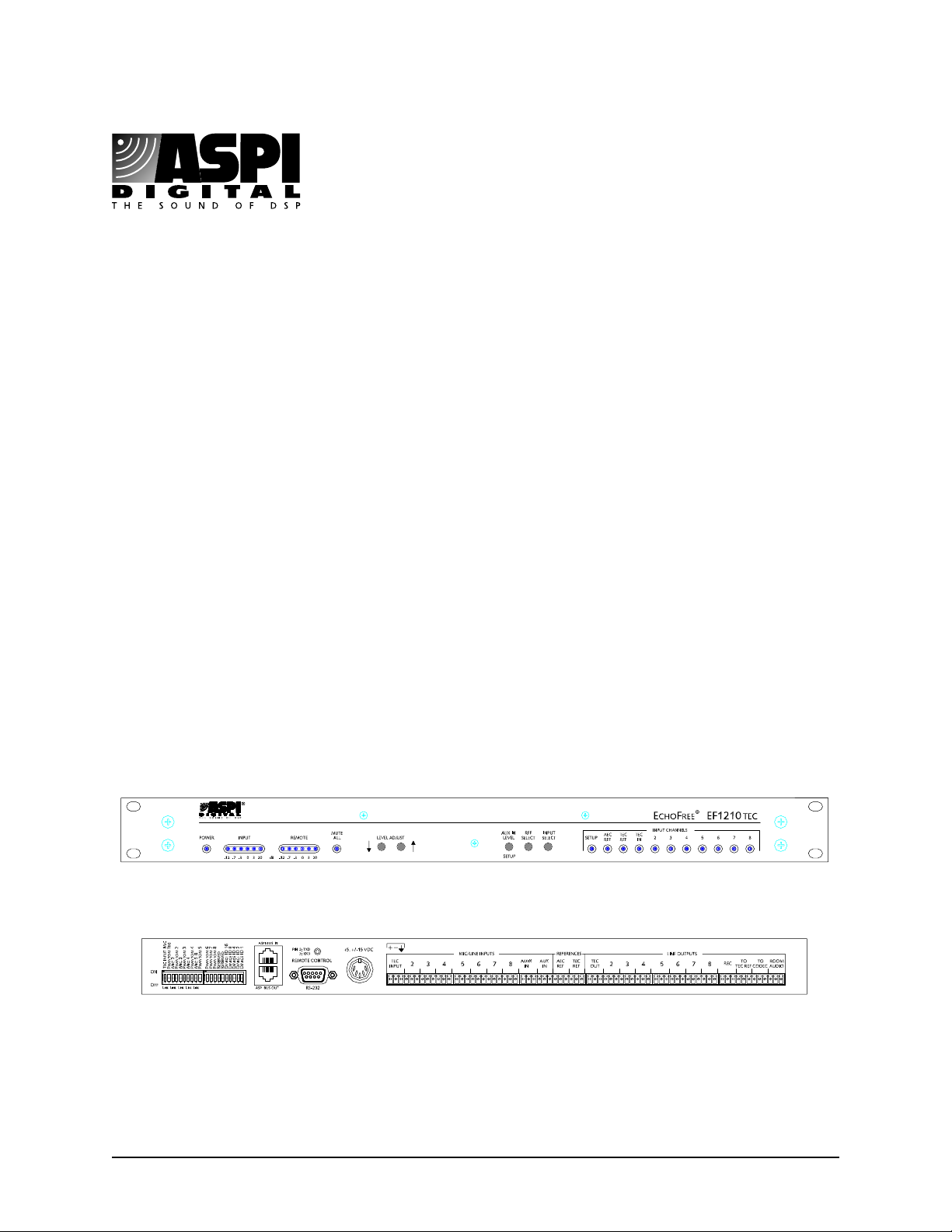
ASPI Digital - The Sound of DSP Application Note: 121
EF1210TEC
Figure 1a: EF1210TEC Front Panel
Figure 1b: EF1210TEC Rear Panel
The connections required for the EF1210TEC are fa irly application s pec ific. The two most
common applications for the EF1210TEC will be described below.
Page 2
Application Note: 121 EF1210TEC Addendum
y
y
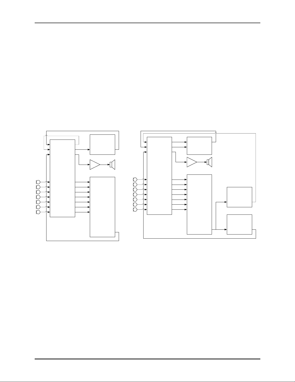
Generating Mix Minus with the EF1210TEC
A system using an EF1210TE C can be confi gured to generate a mix minus. This may be necessary if the system is used with a bridge or MCU tha t does not have mix minus . That is , if the
bridge sends the local site’s audio back to itself. When the E F1 210 is used in this type of
applicati on, it will remove i ts own audio from the incom ing signal, while allowing audio from
other sites to c ome through.
To generate a mix minus, send the mix of all trans mitted audio (including all local microphones) to the TEC Re ference input. Then connect the To CODEC output to the video codec.
This will send local audio to the remote si tes, and give the TEC a reference. Bring the output
of the video code c into the TEC Input. The TEC wil l ca ncel any delayed echo from the codec
signal and pass it on to the TEC Out. This can be sent to the AEC Reference (this signal now
contains audio from the remote sites) and out into the room. The other AEC channels will us e
this reference to prevent acoustic echo fr om being sent back out onto the network.
TEC Input
AEC Ref
TEC Ref
Pla
Amix In
TEC Out
To CODEC
Room Audio
To TEC Ref
EF1210TEC
In 2
In 3
In 4
In 5
In 6
In 7
In 8
Record
Out 2
Out 3
Out 4
Out 5
Out 6
Out 7
Out 8
Video
CODEC
Line In Line Out
Direct Out 1
In 1
Direct Out 2
In 2
Direct Out 3
In 3
Direct Out 4
In 4
Direct Out 5
In 5
Direct Out 6
In 6
Direct Out 7
In 7
Direct Out 8
In 8
8-channel
Automixer
Aux Master Out
TEC Input
AEC Ref
TEC Ref
Pla
Amix In
TEC Out
To CODEC
Room Audio
To TEC Ref
EF1210TEC
In 2
In 3
In 4
In 5
In 6
In 7
In 8
Record
Out 2
Out 3
Out 4
Out 5
Out 6
Out 7
Out 8
In 1
Master Out
In 2
Line Mixer
Direct Out 1
In 1
Direct Out 2
In 2
Direct Out 3
In 3
Direct Out 4
In 4
Direct Out 5
In 5
Direct Out 6
In 6
Direct Out 7
In 7
Direct Out 8
In 8
8-channel
Automixer
Aux Master Out
High Delay
Video CODEC
Line In Line Out
Low Delay
Video CODEC
Line In Line Out
Figure 2a: Mix Minus Configuration Figure 2b: High/Low Delay Configuration
Using the EF1210TEC in High/Low Delay Applications
In some applicatio ns , the signal from another site may arrive from two different paths with different delays. This is not a typical echo problem in which local talkers hear themselves return
through the sys tem. Rather, they will hear talkers from a nother site twice, possibly separated
by several hundred milliseconds. This may occur if some sites are communic ating with each
other over wide bandwidth connections, and also with a larger number of sites on a low bandwidth bridge. The high bandwidth sites may communicate with each other over both the wide
bandwidth and na rrow bandwidth networks. Figure 2b shows how thi s t ype of system may be
connected.
ASPI Digital - The Sound of DSP 2
Page 3

Application Note: 121 EF1210TEC Addendum
Systems with More Than Seven Microphones
If more tha n seven microphones are needed, one or more EF1210s may be added to the system
to provide echo cancella ti on on each micr ophone c hannel . In genera l, only one EF1210T EC is
needed in the room, and st andard EF1210s may be used for addit ional microphones.
ONFIGURING THE
C
OMMAND SET CHANGES
C
TEC
The AEC channels of the EF12 10TEC can be calibrated and conf igured as described in the
EF1210 User Manual.
The EF1210TEC may be configured as a standard EF1210 by setting the DIP switch labelled
“Reserved” next to the Device ID 16 DIP switch. When in the off position, the EF1210TEC
behavior will be selected. In the on position, the standard EF1210 behavior is selected.
There are three new RS-232 commands in the EF1210TEC. They are TDCD, TDCMIN, a nd
TDCMAX (the acronym TDC is use d because these com mands deal with the properties of the
Transmissio n Delay Compensator as describe d in the introduction to this addendum). As with
the EF1210, the de vice type of the EF1210TEC is C.
The TDCD command queries th e del ay detected by the Transmi ssion Delay Compensator.
This command is used for queries only. For example, the command C00TDCD? queries the
delay dete cte d by the EF1210TEC with device ID 0. The command response contains a delay
value in milliseconds (accurate to within a few milliseconds ). If the EF1210TEC were to
return C00TDCD500, the de lay detec ted by the Trans miss ion Dela y Compen sator is abou t 500
milliseconds.
The TDCMIN and TDCMAX commands set the minimum and maximum delay over which
the Transmission Delay Compensator will search fo r echoe s. Reducing the search range may
cause echoes to be found and cancelled more quickly. For instance, if you know the ec ho is
delayed somewhere between 600-800 milliseconds, you can set TDCMIN to 500 ms, and
TDCMAX to 1000 ms. This will allow echoes to be found more quic kly than if the Transm ission Delay Compensa tor had to sear ch over the entire 2 seco nd range. It is important not to set
the range too narrowly, because if the de lay falls outside of the search range, the TE C will not
be able to cancel echoes. The delay is set in milliseconds. Examples of commands are
C00TDCMIN250 and COOTDCMAX750. The curren t settings can be queried with a question mark as the argument.
ASPI Digital - The Sound of DSP 3
 Loading...