

Page 1

E
CHOFREE
™
EF1210
M
ULTI
A
COUSTIC
E
CHO AND
C
ANCELLER
U
SER
-C
M
HANNEL
N
OISE
ANUAL
Page 2

Copyright © 1999 ASPI Digital. All rights reserved. Printed in the United States of America.
Because of technical progress, specifications are subject to change without notice.
EchoFree is a trademark and ASPI is a registered trademark of ASPI Digital.
ASPI Digital - The Sound of DSP
1720 Peachtree Street NW, Suite 220
Atlanta, GA 30309-2439
(404) 892-3200
www.echofree.com
Technical Support:
(404) 892-3200
help@aspi.com
EF1210UM-0100-99
Page 3

EF1210 U
SER MANUAL
Introduction....................................................................................................3
Product Features.................................................................................................... 4
Quick Installation...........................................................................................6
Hardware Installation ............................................................................................ 6
Calibration.............................................................................................................. 6
EF1210 Calibration Quick Reference.................................................................... 8
Advanced Installation ....................................................................................10
Preparing for Installation....................................................................................... 10
EF1210 Front and Rear Panels..............................................................................12
Configuration.......................................................................................................... 15
Connecting the EF1210 to other equipment........................................................... 19
Calibration.............................................................................................................. 27
Calibrating With a Computer................................................................................. 28
Calibrating Without a Computer............................................................................ 28
Calibration Step 1: Calibrating Microphone Input Channels................................29
Calibration Step 2: Calibrating Zone Outputs....................................................... 30
Calibration Step 3: Calibrating AEC Reference Inputs.........................................32
Calibration Step 4: Calibrating for Playback and Record.....................................33
Calibration Step 5: Zone/Reference Setup............................................................. 34
Mounting the EF1210.............................................. ............................................... 36
Operating the EF1210....................................................................................38
Using the EF1210 Without RS-232 Control...........................................................38
Using the EF1210 With RS-232 Control................................................................39
Troubleshooting.............................................................................................42
No Output to Loudspeakers in Zone.......................................................................42
No Output to Remote End....................................................................................... 42
Residual Echo......................................................................................................... 44
Remote Control Problems.......................................................................................47
Contacting Technical Support................................................................................ 48
Technical Specifications................................................................................49
Compliance.............................................................................................................49
Warranty Information ....................................................................................51
EF1210 Command Set Reference..................................................................53
Command Syntax.................................................................................................... 53
Valid Commands and Messages............................................................................. 55
Default Values and Saved Parameter List.............................................................. 84
Applications...................................................................................................85
Distance Learning .................................................................................................. 85
Courtrooms............................................................................................................. 86
Further Assistance..................................................................................................86
EF1210 Block Diagram .................................................................................87
Connector Pinouts..........................................................................................88
Connecting Balanced Equipment to Unbalanced Equipment........................90
Connecting Unbalanced RCA to Balanced Mini Phoenix......................................90
Appendix A: EFPanel Control Software User Manual
About EFPanel Control Software ..................................................................A-3
Installing EFPanel.................................................................................................. A-3
Getting Started......................................................... ............................................... A-3
EFPanel Features for all EF Devices.................................................................... A-3
The EF1210 Options Page.............................................................................A-5
ASPI Digital, Copyright 1999 Technical Support: 404.892.3200 1
Page 4

EF1210 U
SER MANUAL
P
RELIMINARY
Calibrating the EF1210 with EFPanel Control Software...............................A-7
Calibration Step 1: Calibrating Microphone Input Channels................................ A-7
Calibration Step 2: Calibrating Zone Outputs....................................................... A-9
Calibration Step 3: Calibrating AEC Reference Inputs.........................................A-11
Calibration Step 4: Calibrating for Playback and Record.....................................A-13
Calibration Step 5: Zone/Reference Setup............................................................. A-14
Save Setup Settings................................................................................................. A-15
EFPanel for the EF200 Phone Add................................................................A-17
Dialer...................................................................................................................... A-17
Phone Book............................................................................................................. A-18
EF200 Options........................................................................................................A-19
ASPI Digital, Copyright 1999
Technical Support: 404.892.3200
2
Page 5

I
NTRODUCTION
I
NTRODUCTION
Congratulations!
How to Use This
Manual
Congratulations on your purchase of the EchoFree™ EF1210 Multi-Channel Acoustic Echo and Noise Canceller. By choosing AS PI Digital’s Ec hoFree™ products , you
are investing in cutting edge DSP technology that will help provide the best po ssible
audio quality for your system.
This manual is a reference manual for your EF1210. It is structured to provide the
information you need quickly and conveniently. The following is an overview of
each section:
• Quick Installation gives an overview of the installation process including an outline of hardware installation as well as calibration of the EF1210. It also includes
a quick reference for calibration — use the quick reference only if you are very
familiar with the EF1210 since it is just an outline of steps without detailed
explanations.
• Advanced Installation gives more detailed technical information on the installation, configuration and calibration of the EF1210.
• Operating the EF1210 outlines using the EF1210 with and without RS-23 2 control.
• Troubleshooting helps to debug problems with installation.
• Technical Specifications provides the technical specifications of the EF1210.
• Warranty Information
• EF1210 Command Set Reference contains instructions on how to send RS-232
commands to the EF1210 as well as a reference of the RS-232 commands.
• Applications briefly describes using the EF1210 in different applications.
• EF1210 Block Diagram
• Connector Pinouts
• Connecting Balanced Equipment to Unbalanced Equipment
Product Descripti on
ASPI Digital -
The Sound of DSP
The EF1210 Multi-Channel Acoustic Echo and Noise Canceller installs between the
room’s microphones and the automatic mixing system, providing individual channel
noise cancellation and acoustic echo cancellation. The EF1210 works with most vendors’ automixing systems to provide conferencing capability to new and existing
rooms.
Unlike most echo cancellers, the EF1210 requires no training sequence to learn a
room’s echo response. After the unit has been installed, all you have to do is turn it
on. No further adjustments are required. ASPI’s echo cancellation algorithm offers
speed, flexibility and superior audio quality to your conference room setup.
The speed at which an echo canceller matches the actual sound of a room (the convergence rate) is a direct indication of the product’s quality. Faster convergence allows
better conference quality by instantly adapting to chan ging room environments such
as moving microphones, changing volumes or people moving around the room. Our
echo cancellers are designed to provide faster convergence and better performance
than other echo cancellers. This means that the EF1210 adapts to changes in room
acoustics during conversations quickly for consistent performance throughout the
Technical Support: 404.892.3200 3
Page 6

EF1210 U
conversation. At a convergence rate of 30 dB per second, ASPI echo cancellers are
the fastest on the market.
Because the EF1210 supports a wider range of acoustic gain than most echo cancellers, it offers greater flexibility in loudspeaker and microphone placem ent. Most echo
cancellers can only operate properly at less than 0 dB of acoustic gain. Breaking
through this threshold can cause echoes and howli ng as loudspeak er levels overpower
the microphones. Th at can leav e you with f ew options when desig ning audi o or vide o
conference rooms. A wider range of acoustic gain results in a smaller danger zone,
allowing the Systems Designer greater flexibility when placing loudspeakers and
microphones or setting volume levels.
ASPI’s superior audio quality allows all parties to communicate freely and naturally,
without echoes, switching noises, clipping of words, or dropout of speech. A patented state-logic algorithm ensures smooth and natural communications without typical speakerphone performance problems.
ASPI’s proprietary noise cancellation on each of the inp uts helps to keep overall noise
to a minimum. ASPI echo cancellers are the only ones on the market to feature this
patent pending technology. Noise cancellation filters out ambient background noise
such as HVAC, LCD projectors, and road noise. Our noise cancellation technology is
not a noise gate. It actually removes noise. Therefore, it enhances the operation and
improves the sound quality of an automixer, for example, by pre venting it from bringing the noise level up and down when microphones are gated on and off. By cancelling the noise picked up by each microphone, the overall SNR is preserved. The
result is crystal clear speech over a greater decibel range than any other echo canceller. That means reduced listener fatigue and a higher quality audio conference.
SER MANUAL
Warranty
Registration
RODUCT FEATURES
P
The EF1210 is also fully RS-232 controllable via all popular room control systems,
and provides links to other ASPI products, such as the EF200 Phone Add.
Please take a moment to fill out and return your warranty registration card. This
information will help us to provide you with better customer support.
• 8 microphone/line level inputs
• Phantom power on each input
• Ambient noise cancellation (patent pending) on each input
• Fast convergence rate of 30 dB/sec
• Works in environments with up to 10 dB of room gain
• Links to other ASPI devices such as EF200 Phone Add
• Compatible with most matrix and automixers
• Fully RS-232 controllable via room controllers
• Front panel lock-out capability
• Can be used as a wideband noise cancell er (20 kHz band width) when AEC i s disabled
• Long “Tail Time” supports even the most difficult of rooms (200 ms)
• Supports up to two AEC reference input signals
• Supports record and playback
• Ability to store user configurations in non-volatile memory
• Digitally controlled analog trimpots
• Phoenix connectors for audio input and output
• Single rack unit width and height
4 http://www.aspi.com Copyright © 1999, All Rights Reserved
Page 7

I
NTRODUCTION
• Pink noise generator for calibration mode
• 2 year warranty
ASPI Digital -
The Sound of DSP
Technical Support: 404.892.3200 5
Page 8

Q
UICK INSTALLATION
ARDWARE INSTALLATION
H
EF1210 U
Installation of the EF1210 involves two procedures: hardware installation, and calibration.
Hardware installation involves the following steps:
1. Set rear panel DIP switches to select Line or Mic level and enable phantom
power for each microphone input channel, and to select ASPI Bus Device ID if
necessary. See “Configuration” on page 15.
2. Connect input and output signals (See “Connecting the EF1210 to other equipment” on page 19):
• Connect the 8 Mic/Line Inputs to microphones.
• Connect the 8 Line Outputs to the inputs of a mixer.
• Turn off Phantom Power on automixer.
• Connect Zone Output(s) to amplifier(s) or powered loudspeaker(s).
• Connect AEC Reference Inputs to the T
output of a CODEC.
• If you wish to use the EF1210’s bu ilt in P layback/ Record mixer feature, con-
nect A
Record” on page 22.
3. If you are using an RS232 remote control device, connect it to the RS-232
R
EMOTE CONTROL
them using the ASPI Bus ports (See “Connecting the ASPI Bus” on page 26).
4. Connect the external power supply.
, AUX IN, TO CODEC, and REC as directed in “Playback/
MIX IN
port; if you are controlling multiple ASPI devices, connect
AEC output of an EF200 or to the
O
SER MANUAL
ALIBRATION
C
Caution!
Calibration of the EF1210 involves a sequence of five calibration steps to configure
the input and output levels of the EF1210 to match those of the equipment to which it
is connected. The EF1210 can be calibrated either from the front panel or by using a
computer. Please refer to “Calibration” on page 27 for more detailed information on
the Calibration procedure. Correct calibration is essential for satisfactory operation of
the EF1210, so please take the time to familiarize yourself with the details of the Calibration procedure by reading “Calibrati on” on page 27.
For front panel calibration, enter Calibration mode by pressing and holding the A
I
N LEVEL/SETUP
mode, the S
executing. Press the A
to the next. When you have finished Calibration step 5, press the A
button again to exit Calibration mode; any changes that you made will be
S
ETUP
saved as the default power-on settings when you exit the Calibration procedure.
The EF1210 is designed to maintain a 1/4” (6.35 mm) air circulation clearance above the enclosure. Do not stack or install
EF1210s in such a way as to defeat this clearance, block the side
vent holes, or otherwise impe de air circulation around the
EF1210.
and I
NPUT SELECT
LED will blink to let you know which setup step you are currently
ETUP
UX IN LEVEL/SETUP
front panel buttons for 2 seconds. In Calibration
button to move from one Calibration step
UX IN LEVEL
UX
/
6 http://www.aspi.com Copyright © 1999, All Rights Reserved
Page 9

Q
UICK INSTALLATION
If you miss a Calibration step or lose your place and get to the wrong C alibration step,
you may either continue and come back to the missed step later or exit Calibration
mode (by pressing A
UX IN LEVEL/SETUP
repeatedly until the S
LED is no longer
ETUP
illuminated), re-enter Calibration mode, and resume Calibrat ion at the step that you
missed. If you wi sh t o ex it Cal ibration mode and discard any changes that you made,
you must cycle power on the EF1210 before exiting Calibration mode.
ASPI Digital -
The Sound of DSP
Technical Support: 404.892.3200 7
Page 10
EF1210 U
g
g
g
g
SER MANUAL
EF1210 C
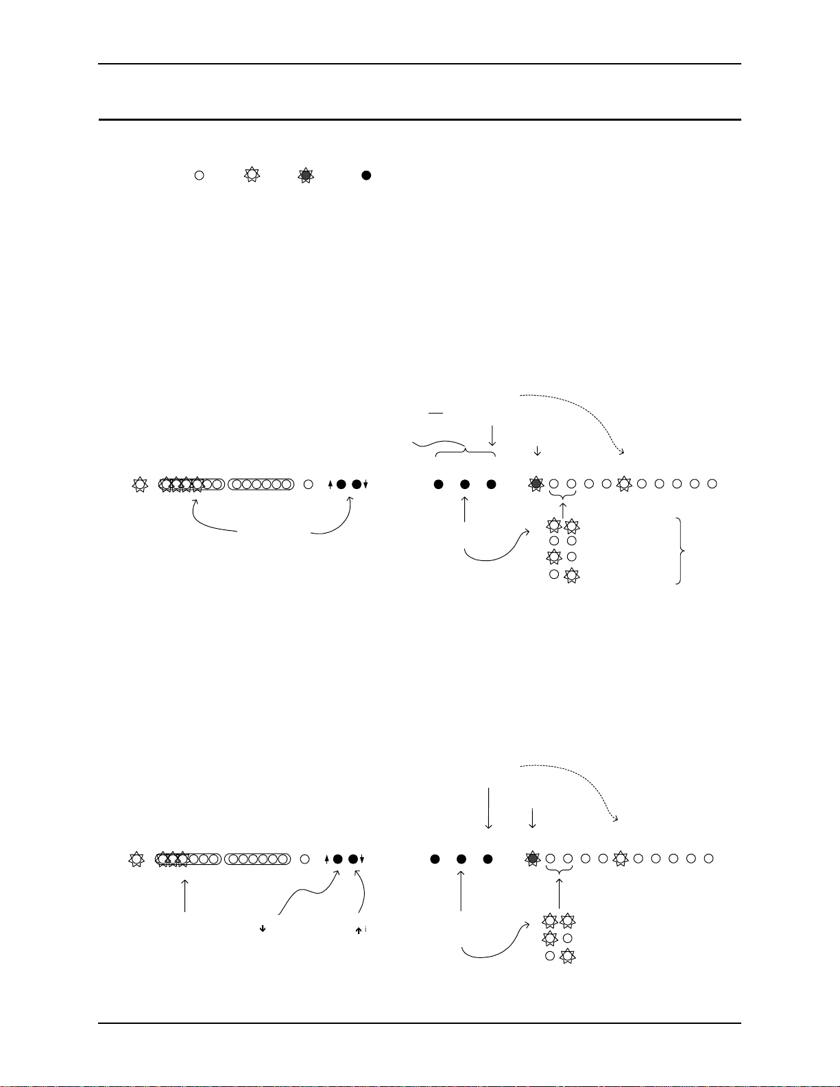
Legend:
ALIBRATION QUICK REFERENCE
LED Off LED On Button
LED Blinking
Calibration Step 1: Calibrating Microphone Input Channels
1.1. Press and hold the AUX IN LEVEL/SETUP and the INPUT SELECT buttons for 2 seconds to enter setup. SETUP LED blinks once
per period.
1.2. Press REF SELECT to select noise output source.
1.3. Press INPUT SELECT to select input channel to calibrate.
1.4. Place SPL meter beside mic pointing in the same direction. Adjust loudspeaker for 73 dB SPL at mic (for boundary mics) or
refer to Table 4 in Calibration Section for other mic types.
1.5. Press LEVEL ADJUST until first yellow LED (0 dB) on INPUT meter is lit on INPUT meter.
1.6. Repeat steps 3-5 for each input channel.
Be sure to move SPL meter or mics so each
mic sees the appropriate SPL level.
: adjust
reen
MUTE
ALL
INPUTPOWER REMOTE
-12 -7 -3 0 3 20 dB -12 -7 -3 0 3 20
STEP 1.5
level until 3
and 1 yellow LEDs
are lit (repeat for
each channel)
STEP 1.1
hold AUX IN LEVEL/
SETUP button
INPUT SELECT for 2
seconds to enter
confi
LEVEL
ADJUST
: Press and
and
uration mode
AUX IN
LEVEL
SETUP
STEP 1.2
select noise source
REF
SELECT
Calibration Step 2: Calibrating Zone Outputs, Check Acoustic Gain
STEP 1.3
:
press to select
channel for
calibration
INPUT
SELECT
: press to
LED blinks
once for
microphone
calibration
AECAAEC
SETUP
LEDs light to
indicate which
channel is selected
12345678
B
pink noise to both zones
no noise
enerated
pink noise to zone A
pink noise to zone B
noise level
measured
at mic
should be
73 dB SPL,
or refer to
Table 4
2.1. Press the AUX IN LEVEL/SETUP button to enter Zone Output Calibration. SETUP LED blinks twice per period.
2.2. Press REF SELECT to select noise output source (we recommend using both zones simultaneously).
2.3. Select nominal output level for your room audio amplifier with LEVEL ADJUST (press UP for 0 dBu, DOWN for -10dBV).
2.4. Repeat for other Zone output if appropriate. Then return all mics to their operating position and orientation.
2.5. Check acoustic gain limit. Adjust external amplifiers/loudspeakers so that the loudspeaker volume is almost uncomfortably
loud OR no more than 3 green LEDs are lit on INPUT meter.
2.6. Press INPUT SELECT to select next input channel.
2.7. If INPUT meter shows more than 3 green LEDs, turn
down room amplifier.
2.8. Repeat steps 6 & 7 for each input channel.
INPUTPOWER REMOTE
-12 -7 -3 0 3 20 dB -12 -7 -3 0 3 20
STEP 2.7
amplifiers/loudspeakers so that
no more than 3
: adjust external
lit (repeat for each channel)
reen LEDs are
MUTE
ALL
STEP 2.3a
: press
Ð
if amp expects
consumer level
input (-10 dBV)
LEVEL
ADJUST
STEP 2.3b
:
if amp
press
Ï
expects 0 dBu
balanced input
STEP 2.6
to select channel;
AUX IN
REF
LEVEL
SELECT
SETUP
STEP 2.2
press to select
noise source
: press
check level
INPUT
SELECT
:
LED blinks
twice for Zone
calibration
AECAAEC
SETUP
channel is selected
12345678
B
noise to both zones (recommended)
noise to zone A
noise to zone B
LEDs light to
indicate which
8 http://www.aspi.com Copyright © 1999, All Rights Reserved
Page 11
Q
UICK INSTALLATION
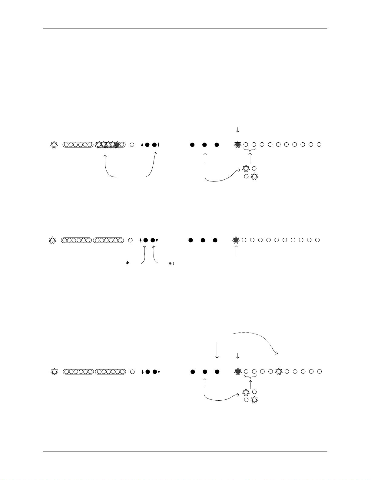
Calibration Step 3: Calibrating AEC Reference Input
3.1. Press AUX IN LEVEL/SETUP button again to enter Ref Input calibration. The SETUP LED blinks 3 times per period.
3.2. Press REF SELECT to select input source (AEC A or AEC B). Single zone installation will use AEC A.
3.3. Establish live connection to remote site(s) and have remote party talk normally.
3.4. Press LEVEL ADJUST until first yellow LED on REMOTE meter is flickering regularly and 2nd yellow is flickering rarely.
3.5. Repeat for other reference input if neccessary.
LED blinks three
times for AEC
Reference calibration
INPUTPOWER REMOTE
-12 -7 -3 0 3 20 dB -12 -7 -3 0 3 20
STEP 3.4
level until person
talking at remote
site flickers second
MUTE
ALL
: adjust
yellow LED
LEVEL
ADJUST
AUX IN
REF
LEVEL
SELECT
SETUP
STEP 3.2
: press
to select
reference input
source
INPUT
SELECT
SETUP
AECAAEC
12345678
B
AEC A input selected
AEC B input selected
Calibration Step 4: Calibrating for Playback and Record
4.1. Press the AUX IN LEVEL/SETUP button to enter Playback/Record calibration. The SETUP LED blinks 4 times per period. This
step may be omitted if you are not using the internal EF1210 mixers to implement playback and record.
4.2. Press LEVEL ADJUST DOWN to set CODEC OUT level to -10 dBV, press LEVEL ADJUST UP to set CODEC OUT level to 0
dBu.
INPUTPOWER REMOTE
-12 -7 -3 0 3 20 dB -12 -7 -3 0 3 20
press Ð to set
CODEC OUT
MUTE
ALL
STEP 4.2a
:
level to -10
dBV
LEVEL
ADJUST
STEP 4.2b
press Ï to set
CODEC OUT
level to 0 dBu
AUX IN
REF
SELECT
INPUT
SELECT
LED blinks four
times for record
LEVEL
SETUP
:
AECAAEC
SETUP
and playback
calibration
12345678
B
Calibration Step 5: Zone/Reference Setup
5.1. Press the AUX IN LEVEL/SETUP button to enter Zone/Reference Setup. The SETUP LED blinks 5 times per period. This step
may be omitted for single zone installations.
5.2. Use INPUT SELECT to cycle through each input channel. Use REF SELECT to select corresponding reference input for each
input channel.
INPUTPOWER REMOTE
-12 -7 -3 0 3 20 dB -12 -7 -3 0 3 20
MUTE
ALL
LEVEL
ADJUST
STEP 5.2a
: press to
select channel for
calibration
AUX IN
REF
SELECT
: press to
INPUT
SELECT
LEVEL
SETUP
STEP 5.2b
select reference zone
LED blinks
five times for
zone/ref setup
AECAAEC
SETUP
LEDs light to
indicate which
channel is selected
12345678
B
zone A selected
zone B selected
ASPI Digital - The Sound of DSP Technical Support: 404.892.3200 9
Page 12

A
DVANCED INSTALLATION
The installation procedure for the EF1210 consists of the following steps:
1. Prepare for installation (below).
2. Configure the DIP switches to accept appropriate levels from microphones or
mixer (See “Configuration” on page 15).
3. Connect the EF1210 to other equipment (See “Connecting the EF1210 to other
equipment” on page 19).
4. Calibrate the EF1210 (See “Calibration” on page 27).
REPARING FOR INSTALLATION
P
Reading the entire manual (or at least the advanced installation section) before beginning the installation process will he lp you be more prepared for installation. Also,
please make sure you have the correct equipment (outlined below) before you begin
installation.
EF1210 U
SER MANUAL
What’s Included
What’s Not Included
Tools Needed
The EF1210 product package includes the following items:
• EF1210 User Manual (this manual)
• EF1210 MultiChannel Acoustic Echo and Noise Canceller
• External Power Supply with a cable clamp for strain relief
• Diskette with EFPanel Control Software
• Warranty R egistration Card
The following equipment is not included with the EF1210 product package, but may
be necessary to create a completely functional system:
• Microphones
• Loudspeakers
• Audio amplifier (or amplified loudspeaker)
• EchoFree™
• Automatic microphone mixer or matrix mixer
• Audio cables
• Videoconferencing CODEC or other four-wire interface (optional)
• RS-232 remote control device (optional)
• Sound Level Meter (SPL meter)
• Screwdriver to mount EF1210 in your rack
EF200 Phone Add (see Note below)
10 http://www.aspi.com Copyright © 1999, All Rights Reserved
Page 13

A
DVANCED INSTALLATION
Note.
The EchoFree™
EF200 Phone Add provides a full duplex inter-
face between a four-wire audio system and a two-wire telephone
line. It allows a telephone caller to be brought in to any four-wire
audio system. The EF200 is similar to a digital hybrid, but with
many more features and capabilities. The primary fu nction of the
EF200 is the line echo canceller (LEC), which digitally eliminates
reflections from the telephone hybrid. The EF200 is the recommended Phone Add for any application.
ASPI Digital -
The Sound of DSP
Technical Support: 404.892.3200 11
Page 14
EF1210 U
SER MANUAL
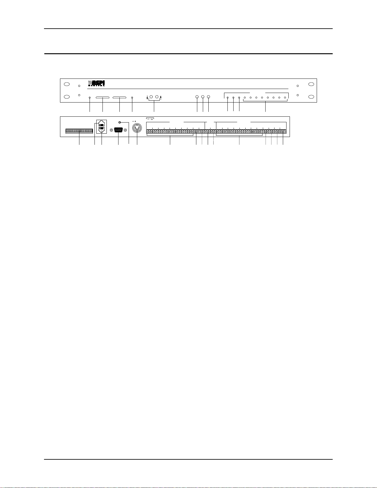
EF1210 F
RONT AND REAR PANELS
S O U N D O F D S
T H E
P
POWER
INPUT REMOTE
-12 -7 -3 0 3 20 -12 -7 -3 0 3 20dB
1 2 3 4 5 6 7 8 9 10 11 12
5
HANTOM
P
6
HANTOM
P
7
HANTOM
P
8
HANTOM
P
ESERVEDRESERVED
R
ASPI BUS IN
PIN 2: TXD
ASPI BUS OUT
3: RXD
REMOTE CONTROLREMOTE CONTROL
RS-232
ID 8
ID 4
ID 2
ID 1
ID 16
EVICE
EVICE
EVICE
EVICE
EVICE
D
D
D
D
D
1
2
3
4
1
2
3
4
5-8
IC
IC
IC
IC
IC
HANTOM
HANTOM
HANTOM
HANTOM
M
P
M
P
M
P
M
P
M
L
INELINELINELINELINE
13 14 15 16 18 19 20 21 22 23 24 25 26 27 2817
MUTE
ALL
Figure 1. EF1210 Front and Rear Panels
1. P
2. I
3. R
4. M
5. L
6. A
7. R
8. I
9. S
10. AEC A LED. During normal operation, this LED indicates if reference input A
11. AEC B LED. During normal operation, this LED indicates if reference input B
12. I
13. D
TM
CHOFREE
INPUT
REF
AUX IN
SELECT
SELECT
LEVEL ADJUST
5, 15 VDC 5, 15 VDC
21
436587
OWER INDICATOR
MIC/LINE INPUTS
LEVEL
SETUP
AEC REF
AUXINAMIX
IN
. When the LED is green, power is on.
NPUT SIGNAL LEVEL INDICATOR
mic input signals (selected by I
EMOTE SIGNAL LEVEL INDICATOR
reference signals (selected by R
UTE ALL
LED. This LED is only ON when all 8 L
E
AEC A AEC B 12345678
SETUP
AEC BAEC A 21436587 REC
INPUT CHANNELS
LINE OUTPUTS
. Indicates level activity on any one of the 8
NPUT SELECT
button).
. Indicates level activity on either of the two
EF SELECT
button).
EF1210
ZONE
TO
ZONE
A
CODEC
B
INE OUTPUT
channels are
muted. If only some of the channels are muted, the LED will not be ON.
EVEL ADJUST
. Adjusts digital trimpot levels for the 8 microphone inputs, 2 reference inputs, 2 zone outputs, CODEC output, and Aux input (used in conjunction with the A
UX IN LEVEL/SETUP
UX IN LEVEL/SETUP
. Press and hold both this button and the I
button).
NPUT SELECT
button for 2 seconds to put the EF1210 into configuration mode. Pressing the
A
UX IN LEVEL/SETUP
calibration process. During normal operation, press and hold the A
button and use the L
S
ETUP
button again selects between configuration modes in the
UX IN LEVEL
EVEL ADJUST
buttons to adjust the playback leve l of
your program audio device.
EF SELECT BUTTON
ence input (AEC A or AEC B) is shown on the R
. During norma l operation, this button selects which refer-
EMOTE LEVEL INDICATOR
. Dur-
ing setup, it has different functions depending on the setup step.
NPUT SELECT BUTTON
of the 8 M
input channels is shown on the I
IC
(LED meter). It is also used with the A
. During normal operation, this button selects which one
NPUT SIGNAL LEVEL INDICATOR
UX IN LEVEL/SETUP
button to enter se tu p
mode. During setup, it has different functions depending on the setup step.
LED. Flashes to indicate the current setup step. This LED is OFF during
ETUP
normal operation.
(AEC A) is selected for display on the R
EMOTE LEVEL INDICATOR
. During
setup, it has different functions depending on the setup step.
(AEC B) is selected for display on the R
EMOTE LEVEL INDICATOR
. During setup,
it has different f unctions depending on the setup st ep.
NPUT CHANNEL
input channel is selected for display on the I
LEDS. During normal operation, these LEDs indicate which
NPUT LEVEL INDICATOR
. During
setup, it has different functions depending on the setup step.
IP SWITCHES
. Select mic or line level inputs, phantom power, and ASPI Bus
ID.
/
12 http://www.aspi.com Copyright © 1999, All Rights Reserved
Page 15

A
DVANCED INSTALLATION
14. ASPI BUS IN. Connects to the ASPI BUS OUT of another ASPI Digital device.
15. ASPI B
US OUT
16. RS-232 R
. Connects to the ASPI BUS IN of another ASPI Digital device.
EMOTE CONTROL PORT
. Connect this to an optional RS-232 remote
control device, such as a touch panel or personal computer COM port.
17. T
HREADED HOLE FOR POWER SUPPLY CABLE CLAMP
. Use the provided cable
clamp to clamp the power supply cable to the back panel of the EF1210 for str ain
relief.
18. P
OWER SUPPLY INPUT
. Connects to the external power supply provided with the
EF1210.
Caution!
Use only the power supply provided with the EF1210. Use
of other power supplies will void the warranty and may
cause damage.
19. M
IC/LINE INPUTS
. Connects to microphone at either mic or line level, with or
without phantom power (both selectable with DIP switches).
20. A
AEC A and is output to R
. Connects to the output of the automixer. This is internally mixed with
MIX IN
. This is only needed when recording from the
EC
EF1210. See “Playback/Record” on page 22 for a description of the Record and
Playback mixer circuitry. See also ‘T
21. A
Note.
UX IN
A
must be a 0 dBu signal.
MIX IN
. Connects to the output of a tape recorder, VCR, or other recording
CODEC” (number 26).
O
device. Playback from a program audio device is only available with the Reference A input signal. See “Playback/Record” on page 22 for a description of the
Record and Playback mixer circuitry.
22. AEC A R
EF INPUT
. Connect to the output of a CODEC or hybrid connected to
Zone A.
23. AEC B R
EF INPUT
. Connect to the output of a CODEC or a hybrid connected to
Zone B.
24. L
INE OUTPUTS
. Connect to the inputs of an automixer or matrix mixer.
Caution!
25. R
EC
. Connects to a recording device. REC requires taking the output from the
Set mixer inputs to 0 dBu line level, phantom power OFF.
automixer (or an output of a matrix mixer) and plugging that back into the
EF1210 so that the local side of the conference can be recorded. See “Playback/
Record” on page 22 for a description of the R ecord and Playback mixer circuitry.
26. T
O CODEC
plugged in to A
. Connects to the CODEC. When the output of the automixer is
MIX IN
, the TO C
signal is a mix of the A
ODEC
MIX IN
and AUX IN
signals. This is only needed when you want to add a Playback signal to the automixer output before it is sent to the C ODEC. See “Pla yback/R ecor d” on page 22
for a description of the Record and Playback mixer circuitry.
27. Z
28. Z
A. Connects to an audio amplifier or powered loudspeaker in Zone A.
ONE
B. Connects to an audio amplifier or powered loudspeaker in Zone B
ONE
(optional).
ASPI Digital - The Sound of DSP Technical Support: 404.892.3200 13
Page 16

EF1210 U
SER MANUAL
How to Get Useful
Information from
the Signal Level
Meters
When configuring the EF1210, it is very important to know which signal level meter
to look at. On the front panel, there are two signal level meters — the I
level meter and the R
(microphones 1-8), use th e I
inputs (AEC A and AEC B), use the R
signal level meter. When configuring the input channels
EMOTE
signal level meter. When configuring the reference
NPUT
signal level meter.
EMOTE
NPUT
signal
Take note that unlike a microphone mixer, the signal level meters do not show a total
output signal, meaning the EF1210 does not add up, for example, all eight input signal levels and show them on the I
signal level meter. Instead, what is shown on
NPUT
the signal level meters is the individual signal level of the inpu t channel or reference.
To display the desired input or reference signal when the EF1210 is in normal opera-
tion (not setup mode), press the appropriate S
button. Push the REF S
ELECT
button to cycle through the two reference inputs. Push the I
NPUT SELECT
button to
ELECT
cycle through the eight input channels. Use the LEDs on the right side of the front
panel as an indicator of which level is displayed on the LED meter. The input channels are indicated by the LEDs labeled C
HANNELS
1-8. Reference inputs are indicated
by the AEC A or AEC B LED.
If you do not see activity on the signal level meter while a talker is talking, do not
immediately assume that the level needs to be turned up. First check to make sure
you are looking at the correct input or reference on the signal level meter.
14 http://www.aspi.com Copyright © 1999, All Rights Reserved
Page 17

A
DVANCED INSTALLATION
ONFIGURATION
C
Configure the DIP
Switches
1
2
3
4
5
6
7
8
ID 8
ID 4
ID 2
ID 1
1
IC
HANTOM
M
P
ON
INELINELINELINELINE
L
2
3
IC
IC
HANTOM
M
M
P
4
5-8
IC
IC
HANTOM
HANTOM
M
M
P
P
HANTOM
P
ESERVEDRESERVED
HANTOM
HANTOM
HANTOM
P
P
P
R
ID 16
EVICE
EVICE
EVICE
D
D
D
EVICE
EVICE
D
D
Figure 2. DIP Switches on EF1210 Back Panel
Note.
S
1 M
2 P
3 M
4 P
5 M
6 P
7 M
8 P
9 M
10 P
#L
WITCH
When the DIP switch is down (as shown in the diagram in Figure
2), it is in the OFF position. When the DIP switch is up, it is in the
ON position. The default factory setting for all switches is OFF.
The following is a description of each DIP switch and its function.
ABEL
1/L
IC
HANTOM
2/L
IC
HANTOM
3/L
IC
HANTOM
4/L
IC
HANTOM
5-8/L
IC
INE
1 Sets phantom power for microphone 1. See Caution below.
INE
2 Sets phantom power for microphone 2. See Caution below.
INE
3 Set phantom power for microphone 3. See Caution below.
INE
4 Sets phantom power for microphone 4. See Caution below.
INE
F
UNCTION
Sets mic or line level for input 1 on the EF1210
Sets mic or line level for input 2 on the EF1210.
Sets mic or line level for input 3 on the EF1210.
Sets mic or line level for input 4 on the EF1210.
Sets microphones 5-8 as a group to accept mic or line level input.
This permits any combination of mic and line level inputs by careful
selection when connecting cables to inputs. Switch 9 in Line position
allows 0-4 microphone inputs; switch 9 in Mic position allows 4-8
microphone inputs.
HANTOM
5 Sets phantom power for microphone 5. See Caution below.
Table 1: DIP Switch configuration
ASPI Digital -
The Sound of DSP
Technical Support: 404.892.3200 15
Page 18

EF1210 U
SER MANUAL
#L
WITCH
S
11 P
12 P
13 P
14 R
15 R
16 D
17 D
18 D
19 D
20 D
ABEL
HANTOM
HANTOM
HANTOM
ESERVED
ESERVED
EVICE
EVICE
EVICE
EVICE
EVICE
6 Sets phantom power for microphone 6. See Caution below.
7 Sets phantom power for microphone 7. See Caution below.
8 Sets phantom power for microphone 8. See Caution below.
ID 16 See Table 2 on page 17
ID 8 See Table 2 on page 17
ID 4 See Table 2 on page 17
ID 2 See Table 2 on page 17
ID 1 See Table 2 on page 17
Table 1: DIP Switch configuration
F
UNCTION
Reserved and must always be set to the OFF position
Reserved and must always be set to the OFF position
Caution!
Phantom power should be turned OFF unless you are
using a microphone that requires phantom power.
16 http://www.aspi.com Copyright © 1999, All Rights Reserved
Page 19

A
DVANCED INSTALLATION
Device ID
Device ID Switch 16
0 (default)
1 ON
2ON
3ONON
4ON
5ONON
6ONON
7ONONON
8ON
9ON ON
10 ON ON
11 ON ON ON
12 ON ON
13 ON ON ON
14 ON ON ON
15 ON ON ON ON
16 ON
17 ON ON
18 ON ON
19 ON ON ON
20 ON ON
21 ON ON ON
These switches set the Device ID for the EF1210. The ID can be any number from 0
to 31. It is a five bit binary number, with the least significant bit on switch 20. The
number after the “Device ID” label denotes the binary value of the switch. Table 2
lists the DIP switch positions necessary to set each Device ID number from 0 to 31.
The Device ID is the same ID that is used with the EF1210 Command Set. The
EF1210 will respond only to commands that are sent with the same Device ID as the
one set on its switches. If you set the Device ID to one that doesn’t agree with your
remote control commands, the remote control will no longer affect that particular
EF1210.
If you are not using a remote control device (via RS-232 o r the ASPI Bus), the Device
ID settings do not matter. The default Device ID is 0.
Table 2: DIP Switch Positions for EF1210 Device IDs (Blank spaces mean switch is OFF)
(Device ID 16)
Switch 17
(Device ID 8)
Switch 18
(Device ID 4)
Switch 19
(Device ID 2)
Switch 20
(Device ID 1)
ASPI Digital - The Sound of DSP Technical Support: 404.892.3200 17
Page 20

EF1210 U
SER MANUAL
Device ID Switch 16
(Device ID 16)
22 ON ON ON
23 ON ON ON ON
24 ON ON
25 ON ON ON
26 ON ON ON
27 ON ON ON ON
28 ON ON ON
29 ON ON ON ON
30 ON ON ON ON
31 ON ON ON ON ON
Switch 17
(Device ID 8)
Switch 18
(Device ID 4)
Switch 19
(Device ID 2)
Switch 20
(Device ID 1)
18 http://www.aspi.com Copyright © 1999, All Rights Reserved
Page 21
A
DVANCED INSTALLATION
ONNECTING THE
C
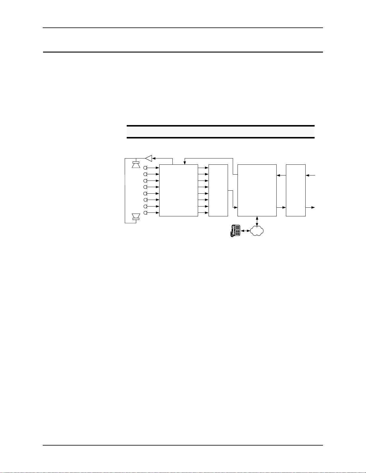
Overview
EF1210 TO
OTHER EQUIPMENT
Each AEC input channel must be associated with 4 signals: local input, local output,
remote input and remote output. The local input can either be a microphone or line
level input. Since the inputs are typically connected to microphones, the inputs will
be referred to as microphone inputs in this manual. The local output is the zon e out-
ONE
A or Z
put (Z
the remote output is the L
Caution!
B). Remote input is the reference input (AEC A or AEC B) and
ONE
INE OUTPUT
.
Set mixer inputs to 0 dBu line level, phantom power OFF.
ZONE A AEC A
CH 1
CH 2
CH 3
CH 4
CH 5
CH 6
CH 7
CH 8
EF1210
OUT 1
OUT 2
OUT 3
OUT 4
OUT 5
OUT 6
OUT 7
OUT 8
Auto
Mixer
TO
AEC
(Optional)
FROM
AEC
EF200
FROM
REMOTE
TO
REMOTE
CODEC
Figure 3. Single room using an EF1210 (single zone).
PSTN
ASPI Digital - The Sound of DSP Technical Support: 404.892.3200 19
Page 22
EF1210 U
SER MANUAL
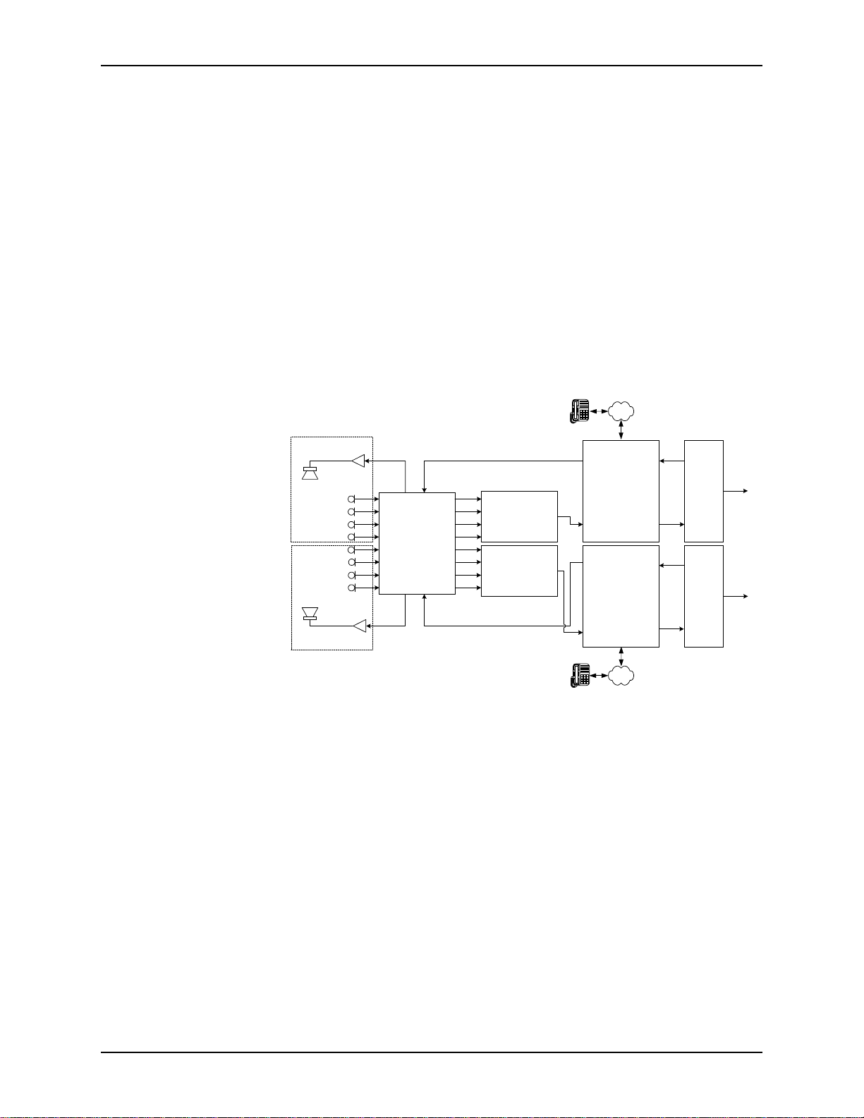
Zoning
The EF1210 may be configured to work with a single AEC reference input or with
two distinct AEC reference inputs. If a single reference is used, the two zone outputs
(Zone A and Zone B) will carry the same signal, and either or both of them may be
connected to room audio amplifiers. An example of using a single reference on the
EF1210 is shown in Figure 3 on page 19. If two references are used, two distinct
zone output signals will be generated, one (Zone A) correspond ing to Reference A
(AEC A) and the other (Zone B) cor responding to Reference B (AEC B). These may,
for example, feed room audio amplifiers in two acoustically isolated areas or rooms.
Each input channel must be associated with exactly one of the two references. By
default, all channels are associated with AEC A. If two references are used, some
microphone input channels will in the soundfield of Z
A and must therefore be
ONE
associated with Reference A (AEC A), while other microphone input channels will lie
in the soundfield of Z
B and must therefore be associated with Reference B (AEC
ONE
B). See Figure 4 on page 20 for a block diagram of using a single EF1210 with two
references and zones.
PSTN
Room A
Room B
CH 1
CH 2
CH 3
CH 4
CH 5
CH 6
CH 7
CH 8
ZONE A AEC A
EF1210
ZONE B AEC B
OUT 1
OUT 2
OUT 3
OUT 4
OUT 5
OUT 6
OUT 7
OUT 8
Auto Mixer (A)
Auto Mixer (B)
TO
AEC
FROM
AEC
TO
AEC
FROM
AEC
REMOTE
EF200 (A)
(Optional)
REMOTE
REMOTE
EF200 (B)
(Optional)
REMOTE
FROM
FROM
CODEC
(A)
TO
CODEC
(B)
TO
PSTN
Figure 4. Two independent rooms using a single EF1210
20 http://www.aspi.com Copyright © 1999, All Rights Reserved
Page 23
A
DVANCED INSTALLATION
Typical EF1210
Connections
1
2
3
4
1
2
3
4
5-8
IC
IC
IC
IC
IC
HANTOM
HANTOM
HANTOM
HANTOM
M
M
M
M
M
P
P
P
P
ON
L
INELINELINELINELINE
5
HANTOM
P
6
HANTOM
P
Remote Control System
ASPI BUS IN
7
8
ID 8
ID 4
ID 2
ID 1
ID 16
EVICE
EVICE
EVICE
EVICE
EVICE
ESERVEDRESERVED
HANTOM
HANTOM
D
P
P
D
R
D
D
D
ASPI BUS OUT
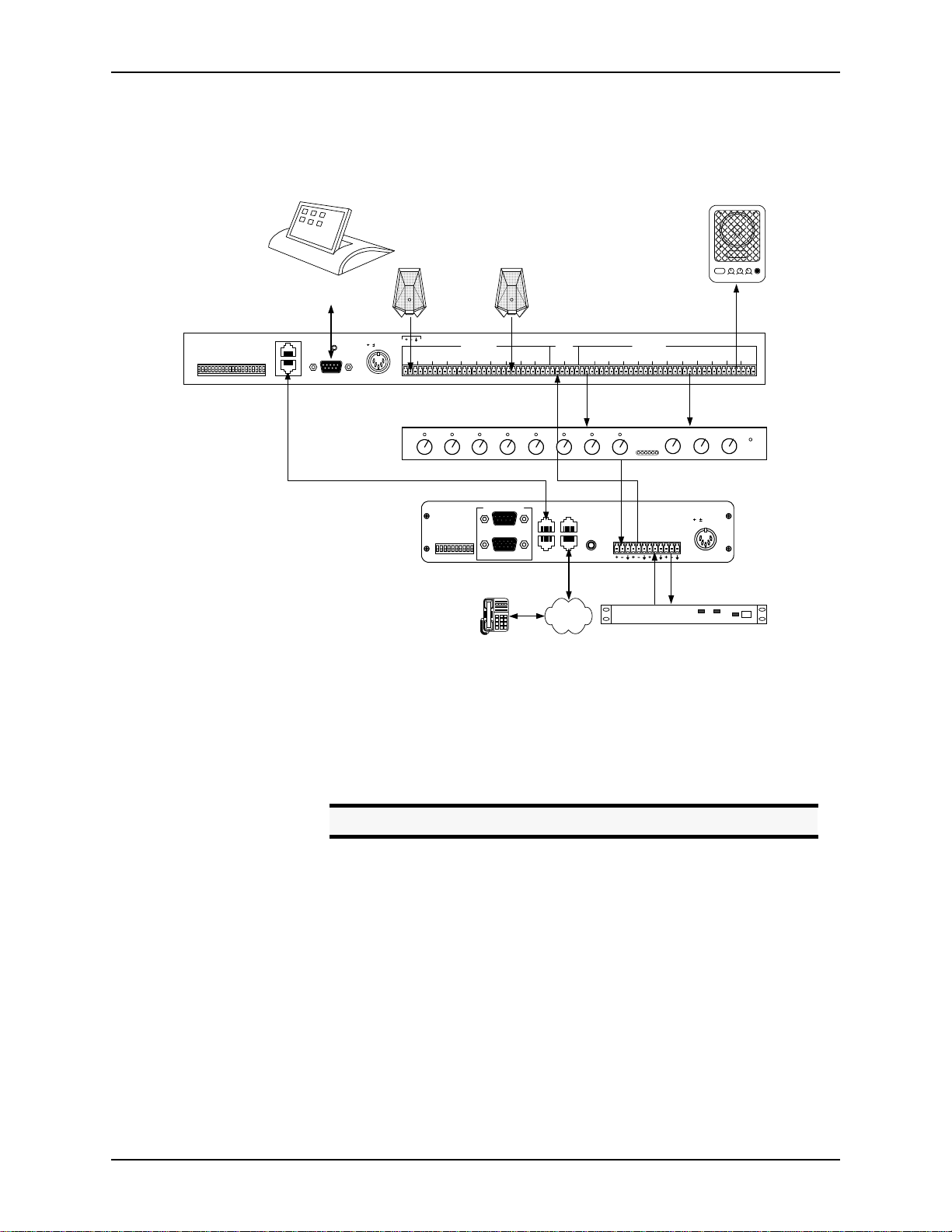
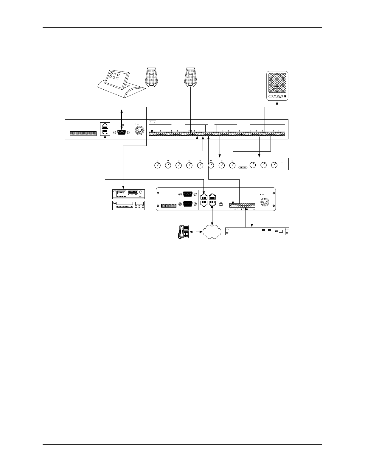
The EF1210 will typically be connected to other equipment in a single zone setup as
shown below in Figure 5.
MI
POWER LOW HIGHVOLUME
microphone
8 microphones
(Optional)
PIN 2: TX
PIN 2: TXD
3: RX
3: RXD
REMOTE CONTROLREMOTE CONTROL
RS-232
5, 15 VDC 5, 12 VDC
15
. . .
MIC/LINE INPUTS
21
436587 PLAY
ASPI Bus Connection for RS-232 Control
)
)
FF
FF
O
O
TO
TO
ET
ET
VERRIDE
(S
(S
UPPRESSION
ID 4
ID 3
ID 2
ID 1
ID 0
O
S
OISE
EVICE
EVICE
EVICE
EVICE
EVICE
ESERVED
ESERVED
PROM
R
N
D
D
D
D
R
D
AGC
E
N
O
FF
O
REMOTE CONTROL
RS-232
LOGIC IN/OUT
microphone
AEC REF
AUX
AMIX
AEC BAEC A 21436587 REC
IN
IN
8 Line Level Signals
Reference
Input
ASPI BUS
TO PHONE
IN
EF400
INTERFACE
ASPI BUS
TO LINE
OUT
EF1210
LINE OUTPUTS
. . .
Automatic
Microphone
Mixer
EF200 Phone Add (Optional)
FROM
AECTOAEC
REMOTETOREMOTE
5, 15 VDC
FROM
POWERED SPEAKER
TO
CODEC
C
ZONE
ZONE
B
A
POWER
Figure 5. Typical EF1210 Connections
• Connect each of the 8 M
accepts mini-Phoenix connectors. See “Connector Pinouts” on page 88 for
pinouts.
• Connect each of the 8 L
mixer. Each L
Caution!
• Connect the zone output (Z
speaker.
• Connect the reference input (AEC A or AEC B) to T
nect only one reference per EF200) or to the output of the CODEC.
• Connect the output of your aut omi xer to F
of your CODEC.
• If RS-232 remote control is desired, connect the RS-232 R
of the EF1210 to the remote control device, such as an RS-232 interface to a
touch panel or a COM por t on a personal computer. Connect the ASPI B
on the EF1210 to the ASPI B
CODEC/hybrid
TX RX
INE INPUT
IC/LINE INPUTS
INE OUTPUTS
INE OUTPUT
PSTN
to a microphone. The MIC/L
to the inputs of an automixer or matrix
uses a mini-Phoenix connector.
Set mixer inputs to 0 dBu line level, phantom power OFF.
A or Z
ONE
on the EF200, if you are using an EF200
US IN
B) to an amplifier or powered loud-
ONE
AEC on the EF200 (con-
O
AEC on the EF200 or to the in put
ROM
EMOTE CONTROL
port
US OUT
ASPI Digital - The Sound of DSP Technical Support: 404.892.3200 21
Page 24
Phone Add.
EF1210 U
SER MANUAL
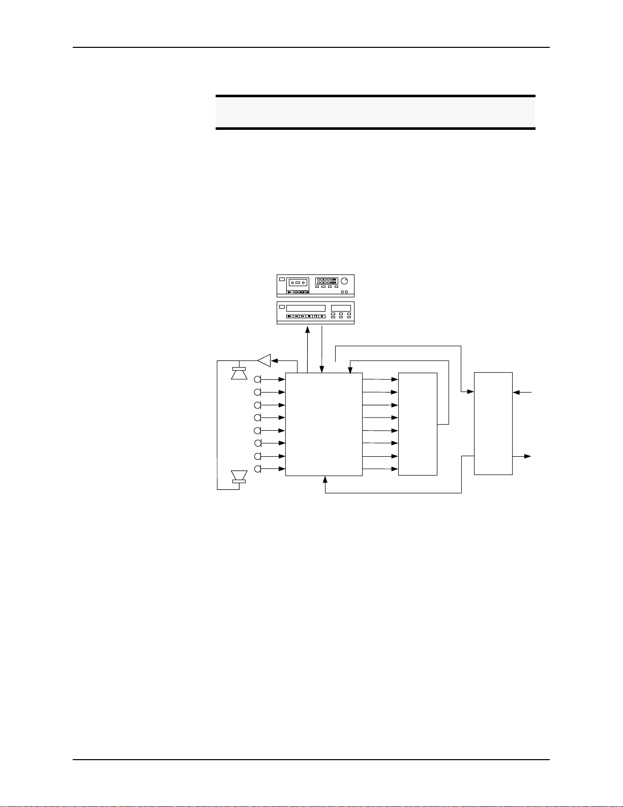
Playback/Record
Note.
The external RS-232 control device may b e co nnected to an y ASPI
device to control all ASPI devices that are linked via the ASPI Bus.
• Connect the external power supply to the P
OWER SUPPLY INPUT
jack of the
EF1210.
The EF1210 provides the capability to record a nd play back audio to y our conference.
Playback allows you to play the audio output of an external device, such as a television or VCR, to the conference. Record allows you to record the audio of the conference to an external device, such as a tape recorder.
auto-reverse
TAPE RECORDER
CH 1
CH 2
CH 3
CH 4
CH 5
CH 6
CH 7
CH 8
VCR
ZONE A
REC
12:00
AUXINTO
CODEC
EF1210
AEC A
AMIX
IN
OUT 1
OUT 2
OUT 3
OUT 4
OUT 5
OUT 6
OUT 7
OUT 8
Auto
Mixer
CODEC
Figure 6.
Block diagram of record and playback connections with the EF1210.
To implement the playback function with the EF1210, a playback signal must be
added to both the local audio (Zone) output and the remote output (the signal sent to
the CODEC or other terminal communication device). To implement the record
function, both the local audio and the remote CODE C signal must be mixed and output to a recording device. Since the remote output will normally be produced by an
automixer external to the EF1210, the output of the a utomixer must be av ailable to be
mixed with the R
and AUX IN signals. This mixing may be implemented using an
EC
external matrix mixer if available, or using the internal mixers provided in the
EF1210. In addition to the convenience of using the EF121 0 mixers, th e EF1210 provides remote control of the level of the A
signal so that weak recordings may be
UX IN
boosted to be audible at both ends.
To use the EF1210 Playback mi xer, the out put of th e automix er must be brough t in to
the A
minal device) must be taken from the T
input on the EF1210 will be added internally to the T
Z
ONE
input on the EF1210, and the input to the CODEC (or other remote ter-
MIX IN
CODEC output of t he EF1210. Th e AUX IN
O
CODEC signal, and also to the
O
A output.
22 http://www.aspi.com Copyright © 1999, All Rights Reserved
Page 25
A
DVANCED INSTALLATION
To use the internal EF1210 Record mixer, the output of the automixer must be
brought in to the A
from the automixer output as well or may be taken from the T
EF1210. The R
EC
input on the EF1210. The input to the CODEC can come
MIX IN
CODEC output of t he
O
output will carry a mix of the A
and the AEC A signals.
MIX IN
Alternatively, you can do this mixing externally (con nect playb ack o utput of ex ternal
program audio device to an automixer input). If record and playback signals are generated using an external mixer, the A
UX IN
and A
inputs and the REC and TO
MIX IN
CODEC outputs will not be used on the EF1210.
Note.
If the EF1210 AUX IN is not used, the playback signal should be
mixed with the AEC Reference signal rather than with the Zone
output signal for local p l ayback.
Playback and record are only available with the Reference A (AEC A) and Zone A
signals. If two zones are used, playback will NOT function properly in Zone B
because it will only be added to Reference A input signal from the far-end.
Using playback and record in the second zone of a multi-zon e system will require
using the matrix mixer to create appropriate mixes outside of the EF1210.
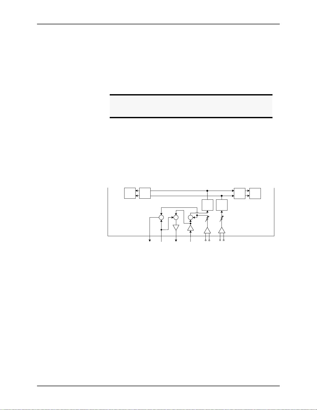
See Figure 7 on page 23 below for the interconnection of A
and REC input and
UX IN
output, respectively.
Ch 3
. . .
AEC
EF1210
Ch 4
AEC
Rec
Amix
In
To
CODEC
Aux
In
+ ++
GainGain
A/D
Level
adjust
Line
+-
AEC
Reference
A
A/D
Level
adjust
Line
+-
AEC
Reference
Ch 5
B
AEC
Ch 6
AEC
. . .
Figure 7.
Playback and Record in the EF1210
To record,
• Connect the R
output of the EF1210 to the audio input on the recording
EC
device.
• Connect A
• Connect T
to the output of the automixer or matrix mixer.
MIX IN
O CODEC
to F
AEC on the EF200 or the input of the CODEC.
ROM
For playback,
• Connect the A
of the EF1210 to the audio output of the playback
UX IN
device.
• Connect A
to the output of the automixer or matrix mixer.
MIX IN
ASPI Digital - The Sound of DSP Technical Support: 404.892.3200 23
Page 26

EF1210 U
SER MANUAL
• Connect TO C
Note.
When using the internal EF1210 Record and Play circuitry, a signal being played back will NOT be reco rd ed to avoid the potential
of a feedback loop caused by the record/playback device.
ODEC
to F
AEC on the EF200 or the input of the CODEC.
ROM
24 http://www.aspi.com Copyright © 1999, All Rights Reserved
Page 27
A
DVANCED INSTALLATION
Figure 8 on page 25 depicts connections on the EF1210 for record and playback.
ON
L
INELINELINELINELINE
microphone
microphone
8 microphones
. . .
MI
POWER LOW HIGH VOLUME
C
Remote Control System
(Optional)
EF1210
LINE OUTPUTS
8 Line Level Signals
. . .
6
HANTOM
P
7
HANTOM
P
8
HANTOM
P
ESERVEDRESERVED
R
ASPI BUS IN
PIN 2: TXD
PIN 2: TX
3: RX
ASPI BUS OUT
3: RXD
REMOTE CONTROLREMOTE CONTROL
ID 8
ID 4
ID 2
ID 1
ID 16
EVICE
EVICE
EVICE
EVICE
EVICE
D
D
D
D
D
1
2
3
4
5
1
2
3
4
5-8
IC
IC
IC
IC
IC
HANTOM
HANTOM
HANTOM
HANTOM
HANTOM
M
M
M
M
M
P
P
P
P
P
RS-232
5, 15 VDC 5, 12 VDC
15
MIC/LINE INPUTS
21
436587 PLAY
AEC REF
AUX
AMIX
AEC BAEC A 21436587 REC
IN
IN
Record Output
Play Input
Automatic
Microphone
Mixer
ASPI BUS
ASPI BUS
IN
OUT
Reference
Input
TO PHONE
EF400
INTERFACE
TO LINE
EF200 Phone Add (Optional)
FROM
FROM
AECTOAEC
REMOTETOREMOTE
ASPI Bus Connection for RS-232 Control
)
)
FF
FF
O
auto-reverse
VCR
TAPE RECORDER
12:00
O
TO
TO
ET
ET
VERRIDE
(S
(S
UPPRESSION
ID 4
ID 3
ID 2
ID 1
ID 0
O
S
OISE
EVICE
EVICE
EVICE
EVICE
EVICE
ESERVED
ESERVED
PROM
R
N
R
D
AGC
E
D
D
D
D
N
O
FF
O
REMOTE CONTROL
RS-232
LOGIC IN/OUT
Record and Play Devices
PSTN
CODEC/hybrid
POWERED SPEAKER
ZONE
TO
A
CODEC
Output to EF200
(optional)
or CODEC
5, 15 VDC
TX RX
ZONE
POWER
B
Figure 8. EF1210 Connections for Record and Playback
ASPI Digital - The Sound of DSP Technical Support: 404.892.3200 25
Page 28
EF1210 U
SER MANUAL
Connecting Multiple
EF1210s
1
2
3
4
5
6
7
8
ID 8
ID 4
ID 2
ID 1
2
3
4
5-8
IC
IC
IC
IC
HANTOM
HANTOM
HANTOM
HANTOM
HANTOM
HANTOM
M
P
M
P
M
P
M
P
P
P
Device ID 0
2
3
4
5
6
7
2
3
4
5-8
IC
IC
IC
IC
HANTOM
HANTOM
HANTOM
HANTOM
HANTOM
HANTOM
M
P
M
P
M
P
M
P
P
P
Device ID 1
HANTOM
P
8
HANTOM
P
ESERVEDRESERVED
R
ESERVEDRESERVED
R
ID 16
EVICE
EVICE
EVICE
EVICE
EVICE
D
D
D
D
D
ID 8
ID 4
ID 2
ID 1
ID 16
EVICE
EVICE
EVICE
EVICE
EVICE
D
D
D
D
D
ON
L
ON
L
1
IC
HANTOM
M
P
INELINELINELINELINE
1
1
IC
HANTOM
M
P
INELINELINELINELINE
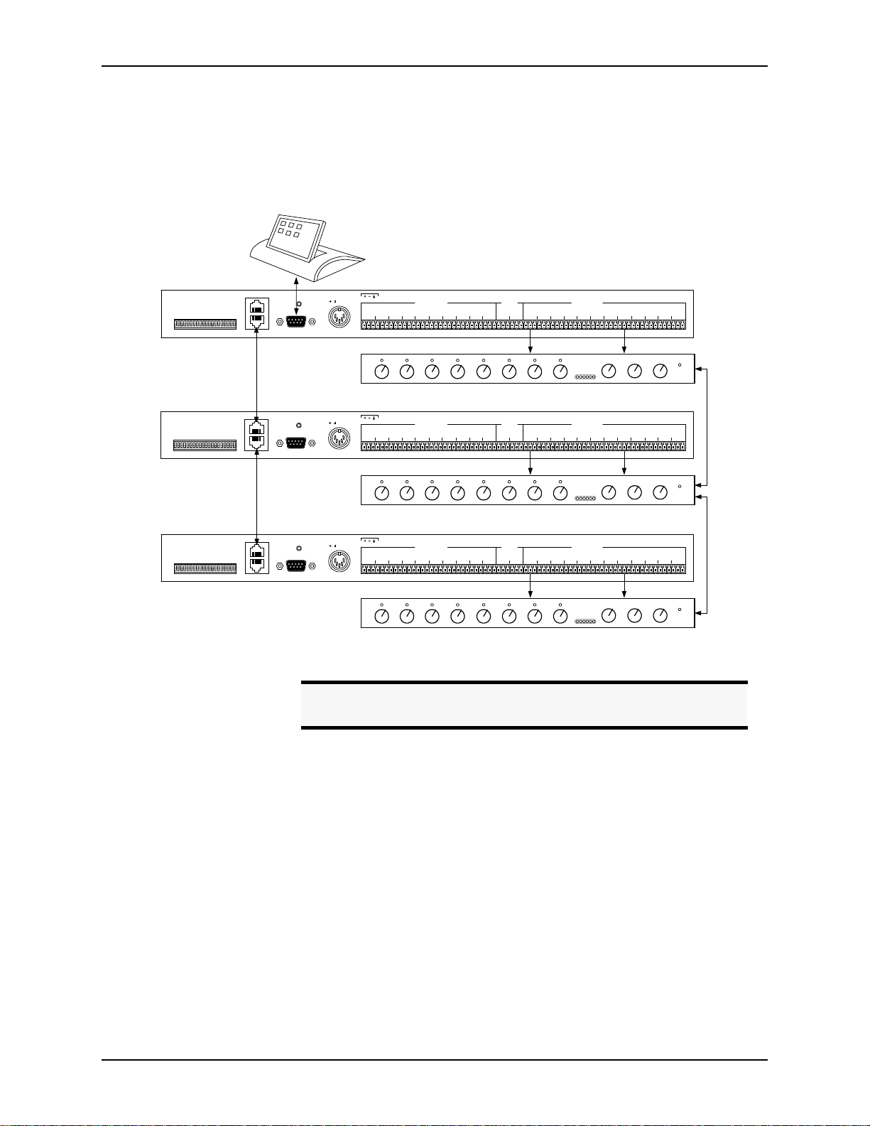
Multiple EF1210s can be easily connected together to add more zones or microphones to your setup. The ASPI Bus allows multiple dev ices to be controlled by a
single RS-232 connection. Reference signals to each EF1210 must still be wired to
each EF1210.
ASPI BUS IN
ASPI BUS OUT
ASPI BUS IN
ASPI BUS OUT
PIN 2: TXD
PIN 2: TX
3: RX
3: RXD
REMOTE CONTROLREMOTE CONTROL
PIN 2: TXD
PIN 2: TX
3: RX
3: RXD
REMOTE CONTROLREMOTE CONTROL
5, 15 VDC 5, 12 VDC
15
RS-232
15
5, 15 VDC 5, 12 VDC
RS-232
MIC/LINE INPUTS
21
436587 PLAY
MIC/LINE INPUTS
21
436587 PLAY
AEC REF
AMIX
AUX
AEC BAEC A 21436587 REC
IN
IN
8 Line Level Signals
AEC REF
AMIX
AUX
AEC BAEC A 21436587 REC
IN
IN
8 Line Level Signals
LINE OUTPUTS
. . .
Automatic
Microphone
Mixer
LINE OUTPUTS
. . .
Automatic
Microphone
Mixer
CODEC
CODEC
ZONE
TO
ZONE
A
POWER
ZONE
TO
ZONE
A
POWER
B
B
6
HANTOM
P
7
HANTOM
P
8
HANTOM
P
ESERVEDRESERVED
R
ASPI BUS IN
PIN 2: TXD
PIN 2: TX
3: RX
ASPI BUS OUT
3: RXD
REMOTE CONTROLREMOTE CONTROL
RS-232
ID 8
ID 4
ID 2
ID 1
ID 16
EVICE
EVICE
EVICE
EVICE
EVICE
D
D
D
D
D
ON
L
1
2
1
2
3
IC
IC
IC
HANTOM
HANTOM
M
P
M
P
M
INELINELINELINELINE
3
HANTOM
P
4
5
4
5-8
IC
IC
HANTOM
HANTOM
M
P
M
P
Device ID 2
Figure 9. Connecting multiple EF1210s
Connecti ng th e
ASPI Bus
The ASPI Bus can connect multiple ASPI Digital products, such as the EF1210, to the
same RS-232 remote control device. This means only one RS-232 connection is
needed to control all devices on the ASPI Bus. Each device on the ASPI Bus should
have a different Device ID or Type ID, so that each device can be addressed and controlled individually. Note that each different type of ASPI Digital product (e.g.
EF200, EF1210) has a distinct Device Type. This means, for example, that an EF200
may have the same Device ID as an EF1210 without causing a conflict. These steps
should be followed to connect the ASPI Bus:
1. Connect the RS-232 remote control device to the first ASPI Digital product in the
2. Connect an ASPI Bus cable between the A
3. Connect an ASPI Bus cable between the A
15
5, 15 VDC 5, 12 VDC
Note.
chain.
the A
SPI BUS IN
the A
SPI BUS IN
MIC/LINE INPUTS
21
436587 PLAY
AEC REF
AUX
AMIX
AEC BAEC A 21436587 REC
IN
IN
8 Line Level Signals
LINE OUTPUTS
. . .
Automatic
Microphone
Mixer
CODEC
ZONE
TO
ZONE
A
B
POWER
The Device ID of each EF1210 should be different from other
EF1210s connected together.
SPI BUS OUT
of the first device, and
of the second device.
SPI BUS OUT
of the second device, and
of the third device, and so on.
26 http://www.aspi.com Copyright © 1999, All Rights Reserved
Page 29

A
DVANCED INSTALLATION
ALIBRATION
C
For the EF1210 to work effectively, it must be calibrated properly to receive correct
levels from the surrounding equipment, such as micropho nes, amplifier, and CODEC.
The calibration procedure is required only to adjust the EF1210 to accommodate the
electrical characteristics of your conferencing equipment. The procedure allows you
to connect the widest po ss ibl e variety of equipment to your EF1210. It does no t t rai n
the AEC. The EF1210 does not require training.
In calibration mode, the EF1210 generates a precise noise signal for measuring the
characteristics and sensitivity of the microphone. You only need to perform this calibration at the initial installation. You do not have to calibrate the EF1210 each time
it is used.
Calibration Steps
Acoustic Gain
Note.
Note.
• Calibration Step 1: Calibrating Microphone Input Channels (page 29)
• Calibration Step 2: Calibrating Zone Outputs, Check Acoustic Gain (page 30)
• Calibration Step 3: Calibrating AEC Reference Inputs (page 32)
• Calibration Step 4: Calibrating for Playback and Record (page 33). This step
may be skipped if you are not using playback and record on the EF1210.
• Calibration Step 5: Zone/Reference Setup (page 34)
Acoustic gain is the maximum amplification that may be applied to a room’s audio
before being picked up by the microphone(s). The volume control may be set at a
lower level than this maximum amplifi cation, but must not be set higher. Too much
acoustic gain occurs if the loudspeaker volume going into the microphone is louder
than the local talker’s volume. This may happen as a result of a combination of the
following setups: the loudspeaker volume is turn ed up too much, the microphone
level is too high, the microphone is too close to the loudspeaker, or the talker is no t
talking close enough to the microphone relative to the loudspeaker volume. Acoustic
gain is commonly misunderstood, so when the audio in a room is not loud enough , it
seems logical to turn up the volume on the amplifier or loudspeaker. This is often not
the best remedy. For example, it may be necessary to tur n up the reference input level
instead. Breaking through the acoustic gain threshold can cause echoes and howling
as loudspeaker levels overpower the microphones.
The calibration procedure will outline how to associate a volume level with the acoustic gain of a room. Refer to “Check Acoustic Gain” on page 31.
When calibrated for the particular microphone and CODEC
setup, the EF1210 will provide years of service without recalibra-
tion. If the signal levels are not calibrated, the performance of the
EF1210 will not be satisfactory. When the signal levels are calibrated correctly, the EF1210 easily and automatically handles any
type of signals and changes in room acoustics to provide unparalleled echo cancellation performance.
If you decide to use a different kind of microphone once the
EF1210 has been calibrated, the microphone inputs on the
EF1210 will be n eed to be recalibr ated.
ASPI Digital - The Sound of DSP Technical Support: 404.892.3200 27
Page 30

EF1210 U
SETUP
SER MANUAL
Two Methods of
Calibration
The EF1210 can be calibrated two ways: calibrating with a computer or wi th out. We
recommend using a computer for calibration because it is an easier procedure and it is
more precise. If you have a computer, please refer to our on-line document for computer calibration procedures. See “Calibrating With a Computer” below for our web
address. If you do not have a computer, please refer to ““Calibr ating Without a Computer” on page 28” for front panel setup.
ALIBRATING WITH A COMPUTER
C
Included in your shipmen t of the EF1210 is a dis kette co ntai ning t he EF Panel C ontro l
Software and a PDF version of the EFPanel User Manual, which includes installation
instructions. Install EFPanel and use it to calibrate the EF1210 with a computer.
Also included is a hardcopy of this manual. This control software and manual may be
changed and updated periodically, so please visit our website at http://www.aspi.com
for the most recent versions.
ALIBRATING WITHOUT A COMPUTER
C
In Calibration mode, the S
are currently executing. The different modes are shown in Table 3 below. Press the
A
UX IN LEVEL/SETUP
you have finished Calibration Step 5, press the A
exit Calibration mode; any changes that you made will be saved as the default poweron settings when you exit the Calibration procedure.
LED will blink to let you know which setup step you
ETUP
button to move from one Calibration s tep to the next. When
UX IN LEVEL/SETUP
button again to
If you miss a Calibration step or lose your place and get to the wrong C alibration step,
you may either continue and come back to the missed step later or exit Calibration
mode (by pressing A
UX IN LEVEL/SETUP
button repeatedly until the S
ETUP
LED is no
longer illuminated), re-enter Calibration mode, and resume Calibration at the step that
you missed. If you wish to exit Calibration mode and discard any changes that you
made, you must cycle power on the EF1210 before exiting Calibration mode.
Legend:
LED Off LED On ButtonLED Blinking
Figure 10. Legend for calibration drawing s.
C
ALIBRATION MODE
MIC Input Calibration S
Z
Output Calibration S
ONE
AEC R
Input Calibration S
EF
Calibrating for Playback and Record S
Zone/Reference Setup S
LED blinks on ce per period
ETUP
LED blinks twice per period
ETUP
LED blinks three times per period
ETUP
LED blinks four times per period
ETUP
LED blinks five times per period
ETUP
Table 3: Visual indication of calibration mode.
28 http://www.aspi.com Copyright © 1999, All Rights Reserved
Page 31

A
DVANCED INSTALLATION
ALIBRATION STEP
C
INPUTPOWER REMOTE
-12 -7 -3 0 3 20 dB -12 -7 -3 0 3 20
Note
ALIBRATING MICROPHONE
1: C
One period equals the number of blinks per step plus one off-time.
.
1.1. Press and hold the AUX IN L
two seconds to enter configuration mode of the EF1210. For Calibration Step 1,
the S
LED will blink once per period. For this step you wi ll need a Sound
ETUP
Level Meter (SPL Meter).
STEP 1.1: Press and
hold AUX IN LEVEL/
SETUP button
INPUT SELECT for 2
seconds to enter
configuration mode
LEVEL
MUTE
ADJUST
ALL
STEP 1.7: adjust
level until 3 green
and 1 yellow LEDs
are lit (repeat for
each channel)
EVEL/SETUP
STEP 1.3:
press to select
and
channel for
calibration
AUX IN
REF
LEVEL
SELECT
SELECT
SETUP
STEP 1.2: press to
select noise source
NPUT CHANNELS
I
button and the I
LED blinks
once for
microphone
calibration
INPUT
SETUP
AECAAEC
B
NPUT SELECT
LEDs light to
indicate which
channel is selected
12345678
pink noise to both zones
no noise generated
pink noise to zone A
pink noise to zone B
noise level
measured at mic
should be at the
appropriate SPL
level from Table 3
button for
Figure 11.
Calibrating Mic Inputs
1.2. If necessary, press the R
1.3. Press the I
1.4. Set the SPL meter (Sound Level Meter) to C weighted, slow response. Choose
Table 4:
EF SELECT
button to select which zone the pink noise is
being played in.
• When you first enter configuration mode, pink noise is played in bo t h Zone
A and Zone B.
•Press R
•Press R
•Press R
EF SELECT
EF SELECT
EF SELECT
• Repeated pressing of R
for no pink noise in Zone A or Zone B.
again for pink noise in Zone A.
again for pink noise in Zone B.
EF SELECT
will cycle through these four modes. See
Figure 11 on page 29.
NPUT SELECT
button to choose the input channe l.
the appropriate dB SPL range using Table 4 below based on microphone type
and the talker’s distance from the microphone.
M
ICROPHONE TYPE
T
YPICAL DISTANCE FROM
T
ALKER (FT
.)
SPL L
(dB)
EVEL
Lavalier 6 inches to 1 foot 89 dB SPL
Gooseneck 1-2 feet 77 dB SPL
Boundary or other tabletop 2-3 feet 73 dB SPL
Ceiling 4 or more feet 69 dB SPL
Typical distance from microphone to talker and appropriate d B SPL l evel .
1.5. Place the SPL meter beside the microphone. Point the SPL meter and the micro-
ASPI Digital - The Sound of DSP Technical Support: 404.892.3200 29
Page 32

phone toward the loudspeaker.
EF1210 U
SER MANUAL
Note
1.6. Adjust the loudspeaker volume so that a nominal dB SPL level based on Table 4
is registered at the microphone.
Note
1.7. Use the L
1 yellow (or 0 dB) LED are lit on the I
1.8. Repeat steps 3 - 7 for all input channels.
1.9. Return all microphones to their normal operating location and orientation.
Note
It is vital to move the SPL meter and/or microphones so that each
.
microphone sees the correct dB SPL acoustic level as you are calibrating. Do not assume that because the first microphone sees
the dB SPL level, all other microphones will see the same level
(unless they are moved to occupy the same location as the first).
Always double check the microphone level with normal speech
.
once the microphones are in normal operating position. Actual
speech levels may vary depending on room reverberation, etc.
Verify that you set a reasonable level (three green LEDs and one
solid yellow LED, or 0 dB) by actually ta lking and looking at the
meter.
EVEL ADJUST
Use caution if the microphones lie in two acoustically sep ar at e d
.
zones and you are only calibrating one zone. As you cycle throug h
microphones that lie in the other zone, no activity will be indicated
on the I
buttons to adjust the channel input gain until 3 green and
NPUT SIGNAL LEVEL METER
NPUT SIGNAL LEVEL METER
.
.
ALIBRATION STEP
C
ALIBRATING ZONE OUTPUTS
2: C
2.1. Once all input channels have been calibrated, press the AUX IN L
button again to switch to Zone Output calibratio n. For Calibration Step 2, the
LED will blink twice per period.
S
ETUP
This step sets the nominal output level of the Zone Ou tputs to match your room
audio equipment. This step also lets you mark the maximum room loudspeaker
amplification level permissible without violating the room acoustic gain limit.
EVEL/SETUP
30 http://www.aspi.com Copyright © 1999, All Rights Reserved
Page 33

A
DVANCED INSTALLATION
INPUTPOWER REMOTE
-12 -7 -3 0 3 20 dB -12 -7 -3 0 3 20
MUTE
ALL
LEVEL
ADJUST
AUX IN
LEVEL
SETUP
STEP 2.6: press
to select
channel;
check level
REF
INPUT
SELECT
SELECT
LED blinks
twice for Zone
calibration
AECAAEC
SETUP
LEDs light to
indicate which
channel is selected
12345678
B
STEP 2.6: adjust external
amplifiers/loudspeakers so that
no more than 3 green LEDs are
lit (repeat for each channel)
STEP 2.3a: press
if amp expects
Ð
consumer level
input (-10 dBV)
Figure 12. Calibrating Zone outputs
2.2. Press the REF S
inal level noise signal is played through the selected Zone output(s).
• When the EF1210 first enters Zone Output cali brati on, the AEC A and AEC
• If you want to calibrate only Zone A, press the R
• If you want to calibrate only Zone B, press the R
2.3. Check the specifications of your room audio amplifier input:
• If it expects consumer level (-10 dBV) input, press the L
• If it has a balanced input connector and expects 0 dBu input level, press the
More precise level adjustments can be made with the RS-232 commands (see the
GAINZ command on page 68 of the Command Set Re ference.
2.4. If you selected only one of the Zone Outputs, repeat for the second Zone Output.
For visual instructions, refer to Figure 12 on page 31.
STEP 2.3b:
press
if amp
Ï
expects 0 dBu
balanced input
STEP 2.2:
press to select
noise source
button to choose which output is being calibrated. A nom-
ELECT
noise to both zones (recommended)
noise to zone A
noise to zone B
B LEDs are lit, indicating that both zones will be calibrated. Use this if you
want to calibrate both zones at the same time.
EF SELECT
button to select
Zone A. Only the AEC A LED lights, indicating Zone A.
EF SELECT
button again to
select Zone B. Only the AEC B LED lights, indicating Zone B.
button once.
D
OWN
L
EVEL ADJUST UP
EVEL ADJUST
button once.
Check Acoustic Gain.
2.5. At this point you are ready to calibrate the absolute maximum room audio amplification level. For this step, you should ensure that the micro phone s have been
returned to their normal operating location and orientation. This procedure uses
a known nominal electrical noise signal level at the zone output to let you see if
any of the microphone input channels will exceed the permissible acoustic gain
during normal conferencing operation. The level of this noise signal is such that
if any microphone input channel registers more than three green LEDs on the
EF1210 I
NPUT SIGNAL LEVEL METER
channel has been reached. This represents the maximum amplification that may
be applied to the roo m audi o. The r oom audi o may be run at any lev el below th is
threshold, but should not be amplified beyond this level unless the acoustic gain
is reduced by some other means (See “Acoustic Gain” on page 44).
All microphones should be checked in this step as verification that no microphone inputs or zone outputs have been miscalibrated.
ASPI Digital - The Sound of DSP Technical Support: 404.892.3200 31
, the acoustic gain limit of that microphone
Page 34

EF1210 U
As above, both Zones can be adjusted at the same time (both AEC A and AEC B
LEDs will be lit indicating Zone A and Zone B). This is recommended because
you can check all Input Channels at the same time. Alternatively, if necessary,
you may select either Zone by pressing R
LED is lit and check one Zone at a time.
EF SELECT
until the appropriate AEC
SER MANUAL
Note.
Adjust the external room audio ampl ifiers/loudspeakers until either:
• The loudspeaker audio level is about to become uncomfortably loud.
OR
• Three green LEDs on the EF1210 I
2.6. Next, step through the microphone input channels by pressing the I
button, while verifying for each channel that the first yellow (0 dB) LED is not lit
on the I
• If the first yellow (0 dB) LED is lit for any channel, turn down the room
Note
You should start by sel ecting (using t he I
checking the microphone input channel which is closest to the
loudspeakers or the microphone which might be expected to pick
up the most acoustic energy from the loudspea ker audio , as appro priate. Check the acoustic gain of this microphone using Step 5,
then quickly step through each of the microphone channels (step 6)
to verify that no other microphone has a stronger signal.
NPUT SIGNAL LEVEL METER
the first yellow (0 dB) LED is not lit for the chosen input channel
NPUT SIGNAL LEVEL METER
audio amplifier on the corresponding Zone Output or turn down the gain on
that microphone channel.
Do not turn up the room audio level at any point after Step 5.
.
.
NPUT SELECT
button) and
are lit, but
NPUT SELECT
ALIBRATION STEP
C
2.7. When all input channels have been checked, you can mark the positions of the
volume controls on the room audio amplifiers and note that this is the absolute
maximum amplification that may be applied to room audio. This maximum
amplification will be referred to in this manual as the amplifier acoustic gain
limit.
Note
During normal operation, the zone output levels will be set 6 dB lower than the
selected level (amplifier acoustic gain limit) to allow the EF1210 L
trols to apply a volume ad j us tme nt t o the room audio signal in the range +6 dB to -12
dB.
Refer to Figure 12 on page 31 for further explanation.
ALIBRATING
3: C
3.1. Once the Zone Output channels and room audio amplifier have been calibrated,
press the A
The volume control may be set at a lower level than this marked
.
position (amplifier acou stic gain limit), but must not be set higher
or the performance of the echo canceller will be suboptimal.
EVEL ADJUST
AEC R
UX IN LEVEL/SETUP
EFERENCE INPUTS
button again to switch to AEC Reference Input
con-
32 http://www.aspi.com Copyright © 1999, All Rights Reserved
Page 35

A
DVANCED INSTALLATION
INPUTPOWER REMOTE
-12 -7 -3 0 3 20 dB -12 -7 -3 0 3 20
STEP 3.4: adjust
level until person
talking at remote
site rarely flickers
second yellow LED
calibration. For Calibration Step 3, the S
LED will blink three times per
ETUP
period.
For this step, you will need a live connection to a remote conferencing site (or
two sites if you are configuring the EF1210 for two AEC reference inputs).
• If you are configuring the EF1210 for operation with one AEC reference
input, you will calibrate the AEC A signal.
• If you are configuring the EF1210 for operation with two AEC reference
inputs, you will calibrate both the AEC A and the A EC B signals.
LED blinks three
times for AEC
Reference calibration
MUTE
ALL
LEVEL
ADJUST
AUX IN
REF
LEVEL
SELECT
SETUP
STEP 3.2: press
to select
reference input
source
INPUT
SELECT
SETUP
AECAAEC
12345678
B
AEC A input selected
AEC B input selected
Figure 13. Calibrating AEC Reference Inputs
3.2. Press R
by the front panel AEC A and AEC B LEDs. During this step, all other LEDs
(I
NPUT CHANNEL
3.3. Have the person at the remote end of the conferencing link sit at a normal distance from a microphone and ta lk at a normal level while you obs erve the signal
activity on the R
3.4. Adjust the AEC Reference Input by pressing the L
first yellow (0 dB) LED lights regularly during normal speech at the remote end,
and the second yellow LED flickers occasionally.
3.5. If you are calibrating two AEC Reference Inputs, switch to the other by pressing
R
EF SELECT
Caution!
Refer to Figure 13 on page 33.
ALIBRATION STEP
C
ALIBRATING FOR PLAYBACK AND RECORD
4: C
EF SELECT
to select between AEC A and AEC B. This will be indicated
) will be extinguished.
EMOTE SIGNAL LEVEL METER
.
EVEL ADJUST
and repeat the calibration for the second reference signal.
If you skip this calibration step, you will compromise the
performance of the EF1210. The audio coming from the
remote end may be too low, so if you turn up the loudspeaker to compensate, the acoustic gain will be affected.
buttons until the
4.1. Once the AEC Reference Inputs have been calibrated, press AUX IN L
again to switch to Playback/Record calibration. For Calib rat ion Step 4,
S
ETUP
the S
LED will blink four times per period. This step calibrates the TO
ETUP
EVEL
/
ASPI Digital - The Sound of DSP Technical Support: 404.892.3200 33
Page 36

EF1210 U
SER MANUAL
CODEC signal. No other calibration is necessary for Playback/Record.
CODEC signal may be adjusted to match the level required by your
The T
O
codec (or other remote terminal equipment) input.
INPUTPOWER REMOTE
-12 -7 -3 0 3 20 dB -12 -7 -3 0 3 20
Figure 14.
Calibrating for playback and record.
Note.
You may skip this step if you are not usin g pl ayb ack an d record on
the EF1210
LED blinks four
times for record
and playback
calibration
MUTE
ADJUST
ALL
STEP 4.2a:
press Ð to set
CODEC OUT
level to -10
dBV
4.2. Press the L
Press the L
LEVEL
STEP 4.2b:
press Ï to set
CODEC OUT
level to 0 dBu
EVEL ADJUST DOWN
EVEL ADJUST UP
AUX IN
REF
LEVEL
SETUP
SELECT
INPUT
SELECT
SETUP
AECAAEC
12345678
B
button to set the TO CODEC level to -10 dBV.
button to set the TO CODEC level to 0dBu. More
precise level adjustments can be made with RS-232 commands (See the GAINC
command on page 62 in the Command Set Reference.).
Refer to Figure 14 on page 34.
ALIBRATION STEP
C
ONE/REFERENCE SETUP
5: Z
5.1. Enter Zone/Reference Setup mode by pressing AUX IN L
ping through the normal configuration sequence. For Calibration Step 5, the
LED will blink five times per period.
S
ETUP
If you are only using a single zone, you may omit this step.
During Calibration Step 5, you may set the EF1210 to use different AEC Reference Inputs for each channel. The reference signal used with channel 1 will be
used as Zone A output, and the reference used with channel 8 will be used as
Zone B output. Microphones on the input channels must be placed in the sound
field of the appropriate Zone output for the EF1210 to operate correctly; otherwise echoes will not be cancelled. In other words, if for example the microphone
on channel 3 is in the soundfield of the loudspeaker connected to the Zone B out-
EVEL/SETUP
after step-
34 http://www.aspi.com Copyright © 1999, All Rights Reserved
Page 37

A
DVANCED INSTALLATION
put, channel 3 must be configured to use Reference B (AEC B) as its reference.
INPUTPOWER REMOTE
-12 -7 -3 0 3 20 dB -12 -7 -3 0 3 20
Note
MUTE
ALL
If you are using only one reference signal (Reference A), all
.
microphones must be configured to use that reference signal. If
you are using two reference signals (Reference A and Reference
B), Input Channel 1 must be associated with Reference A (AEC A)
and Input Channel 8 must be associated with Reference B (AEC
B). The other 6 microphones can be associated with either reference.
STEP 5.3: press to
select channel for
LEVEL
ADJUST
calibration
AUX IN
REF
SELECT
INPUT
SELECT
LEVEL
SETUP
STEP 5.2: press to
select reference zone
LED blinks
five times for
zone/ref setup
AECAAEC
SETUP
B
LEDs light to
indicate which
channel is selected
12345678
zone A selected
zone B selected
Figure 15.
Zone/Reference Setup
5.2. Use the R
5.3. Press the I
5.4. You may now exit configuration mode and resume normal operation by pressing
Refer to Figure 15 on page 35.
EF SELECT
button to select an AEC Reference (AEC A or AEC B) to be
used with the channel indicated by the Input channel LEDs. The AEC A or AEC
B LED will illuminate to indicate the selected reference.
NPUT SELECT
button to select the next input channel, and select AEC A
or AEC B as reference for that channel. Continue until all eight input channe ls
have been configured.
the A
UX IN LEVEL/SETUP
Note
Once you enter setup from the front panel, the configura tion will
.
button.
be saved as the power-on default once you exit setup. If you wish
to discard any changes you made, you must cycle power on the
EF1210 before you press the S
button to exit Setup.
ETUP
ASPI Digital - The Sound of DSP Technical Support: 404.892.3200 35
Page 38

OUNTING THE
I
M
EF1210
The EF1210 can be mounted in a rack enclosure using four large screws (10-32 x 1/
2”) included with the unit. One EF1210 fits in a single rack space.
EF1210 U
SER MANUAL
Recommendation
For Easy Access
Instructions for
Securing Power
Supply to Back of
EF1210
Thread power cable through cable clamp and attach to
EF1210 back panel for strain relief on the power supply.
ON
1
2
3
1
2
3
IC
IC
IC
HANTOM
HANTOM
HANTOM
P
P
P
M
M
M
L
INELINELINELINELINE
While not required, it is prudent to leave a single rack space in between the EF1210
and other units in your rack. This not only is a good design practice, but also gives
you easier access to the backpanel. If you cannot leave a single rack space, mount the
EF1210 below units that are longer in length so that you can access the Phoenix connectors on the backpanel more easily.
• Locate the cable clamp on the back panel of the EF1210 above the RS-232 port.
• Remove the screw and thread the power cord through the cable clamp.
• Attach the cable clamp to the back panel of the EF1210 and tighten the screw.
Align the clamp so that the power cable does not interfere with the connectors on
the EF1210 ba ckpanel.
• Plug in the power supply.
• We recommend that you also Ty-wrap the power supply to the rack.
4
IC
M
4
5
5-8
IC
HANTOM
HANTOM
P
P
M
6
7
8
ESERVEDRESERVED
HANTOM
HANTOM
HANTOM
R
P
P
P
ID 8
ID 16
EVICE
EVICE
D
D
ID 4
EVICE
D
ID 2
EVICE
D
ID 1
EVICE
D
ASPI BUS IN
ASPI BUS OUT
PIN 2: TX
PIN 2: TXD
3: RX
3: RXD
REMOTE CONTROLREMOTE CONTROL
RS-232
15
5, 15 VDC 5, 12 VDC
MIC/L
21
435
Figure 16. Attaching a cable clamp to the back panel of the EF1210
The purpose of securing the power supply to the back panel is so that if the power
supply were to drop, it would pull where the cord is attached with the cable clamp and
not pull the plug out of the EF1210.
36 http://www.aspi.com Copyright © 1999, All Rights Reserved
Page 39

A
DVANCED INSTALLATION
Caution!
Caution!
Caution!
Caution!
Caution!
Caution!
Do not use any other power supply other than the one provided
with this unit.
Failure to use all four screws to attach the E F1210 to the rack
may result in uneven loading and cause a safety hazard.
Ensure that the power supply is securely located such that it cannot become dislodged and fall. Such a fall could cause personal
injury or equipment failure .
When mounting an EF1210 in a rack, consideration should be
given to airflow and operating ambient temperatures inside the
rack. To ensure safe operation of the EF1210, ambient operating
temperatures inside the rack should not exceed 50 degrees Celsius. Allow 2 inches of open space in fro nt of the EF1210, two
inches on either side, and four inches behind the unit for proper
ventilation. Equipment should not be installed in the rack in such
a way as to interfere with the ventilation of the EF12 10.
The EF1210 enclosure is designed to maintain a 1/4” clearance
above the top of the u n it. Do not instal l or s t ack EF 121 0s i n su ch
a way as to defeat this clearance.
Do not block the vents on the sides of the EF1210.
Caution!
Caution!
Consideration should be given to the connection of the equip-
ment to the supply circuit and the effect that overloading of circuits could have an overcurrent protection and supply wiring.
Appropriate consideration of equipment nameplate ratings should
be used when addressing this concern.
Reliable earthing of rack-mounted equipment should be main-
tained. Particular attention should be given to supply connections
other than direct connection to the Branch (use of power strips).
ASPI Digital - The Sound of DSP Technical Support: 404.892.3200 37
Page 40

EF1210 U
SER MANUAL
O
PERATING THE
SING THE
U
EF1210 W
Changing Level
Display on
LED Meters
EMOTE
R
I
NPUT
and
Adjusting Volume in
Zones
EF1210
ITHOUT
When the EF1210 is in normal o perating mo de, pushin g the I
allow you to see levels of each input channel on the I
LED corresponding to an input channel will light if the levels of that channel are currently displayed on the I
button will allow you to see the levels of each reference input on the R
meter. A yellow LED will indicate which reference (AEC A or AEC B) is displayed
on the meter.
The reference LEDs (AEC A or AEC B) do double duty. They not only indicate
which Reference Input is currently displayed on the R
indicate which Zone Output is affected when the L
The AEC A LED indicates that Z
A
DJUST
by the L
12 dB below the nominal zone output level. The nominal zone output level is 6 dB
below the level selected in Calibration Step 2: Calibrating Zone Outputs.
RS-232 C
button. The AEC B LED indicates that Z
EVEL ADJUST
ONTROL
NPUT SELECT
LED meter. The green
NPUT
LED meter. In the same way, pushing the REF S
NPUT
EMOTE
LED meter, but also
EMOTE
EVEL ADJUST
A’s volume is being adjusted by th e L
ONE
B’s volume is being adjusted
ONE
button. The output levels can be ad justed up to 6 dB abov e and
buttons are pressed.
button will
ELECT
LED
EVEL
Adjusting Playback
Levels
Muting
Splitting zones
The AUX IN input and REC output signals are preset to -10 dBV signal levels. The
level of the A
low or high audio level from an external playback device.
1. During normal operation, press and hold the A
using the L
level-adjusted A
and sent to the T
and played over the Zone A output.
To mute channels while using the EF1210 without RS-232 control, for push-to-talk
microphones for example, we suggest using the mute control capability on the mixer
rather than using a microphone with mute built inside it. The AEC will perform better using this method because it allows the speech to be processed inside the EF1210
before being muted instead of totally cutting off the speech so that the AEC has to
readapt when the microphone comes on again.
Calibrate using calibration procedures. When using more than one zone, refer to
“Calibration Step 5: Zone/Reference Setup” on p age 34 to associate each microphone
input channel with a reference. If you are using two reference signals (Reference A
and Reference B), Input Channel 1 must be associated with Reference A (AEC A)
and Input Channel 8 must be associated with Reference B (AEC B). The other 6
microphones can be associated with either reference
signal may be adjusted during nor mal operation to compensat e for
UX IN
UX IN LEVEL/SETUP
EVEL ADJUST
UX IN
O
buttons to adjust the level of the playback signal. The
signal is mixed with the A
CODEC connector. It is also mixed with the AEC A signal
signal (nominally 0dBu)
MIX IN
button while
38 http://www.aspi.com Copyright © 1999, All Rights Reserved
Page 41

O
PERATING THE
EF1210
SING THE
U
EF1210 W
Serial Port Setup
Changing Level
Display on
R
EMOTE
I
NPUT
LED Meters
and
ITH
RS-232 C
You can control all of the EF1210’s features with an RS-232 remote control device.
The instructions below explain which RS-232 commands are needed to accomplish
each function. Users may not need to know these commands, since they may be hidden behind the user interface of the remote control device. A full Command Set Reference is provided at the end of this manual starting on page 53.
For RS-232 control, use an RS -232 cab le — do not us e a null modem . Refer to “Co nnector Pinouts” on page 88 for pin connections for the RS-232 cable. The RS-232
port on the remote control device should be set to 9600, 8-N-1.
When the EF1210 is in normal operating mode, the input channel level displayed on
the I
from the RS-232 command set:
Command Description Effects
SELECTI
SELECTI? Request current
LED meter can be checked and adjusted using the following commands
NPUT
n
ONTROL
Set front panel
LED meter to
I
NPUT
display input channel n.
assignment of front
NPUT
LED
panel I
meter.
The level of input channel n will be
displayed on the I
and the green LED of the channel will
light.
The EF1210 returns channel n, which
indicates that the front panel I
LED meter is currently set to display
input channel n.
n ranges from 1 to 8.
LED meter
NPUT
NPUT
When the EF1210 is in normal operating mode, the Reference Input level displayed
on the R
mands from the RS-232 command set::
Command Description Effects
SELECTR
SELECTR? Request current
LED meter can be checked and adjusted using the following com-
EMOTE
c
Set front panel
EMOTE
LED meter
LED
EMOTE
R
to display Reference
input c.
assignment of front
panel R
meter.
The level of Reference input c will be
displayed on the R
and the yellow LED of the reference
will light.
The EF1210 returns Reference input c
which indicates that the front panel
R
display Reference input c.
c is either A or B.
LED meter is currently set to
EMOTE
EMOTE
LED meter
ASPI Digital -
The Sound of DSP
Technical Support: 404.892.3200 39
Page 42

EF1210 U
SER MANUAL
Adjusting Volume in
Zones
Adjusting Playback
Levels
The volume in the zones can be checked and adjusted using the following commands
from the RS-232 command set:
Command Description Effects
GAINZ
c
x Set zone c output
gain to x.
c
GAINZ
During normal operation, the zone output levels will be set 6 dB lower than the
selected level (amplifier acoustic gain limit) to allow the EF1210 L
trols to apply a volume ad j us tme nt t o the room audio signal in the range +6 dB to -12
dB.
The AUX IN input and REC output signals are preset to -10 dBV signal levels. The
level of the A
low audio level from an external playback d evice. The playback level can be adjusted
using the following commands from the RS-232 command set:
? Request zone c out-
put gain.
Note.
See the “GAINZc - set ZON E output gain on outp ut c” on p age68
for a more detailed descrip tion of the zone output gain x.
signal may be adjusted during nor mal operation to compensat e for
UX IN
Zone c output gain set to x dB; yellow
LED on AEC c will light.
c is either A or B.
x ranges from 0 to 20 dB.
Current gain for zone c is returned to
remote control device.
EVEL ADJUST
con-
Muting
Command Description Effects
GAINPx Set playback input
gain to x.
GAINP? Request playback
input gain.
Note.
The channels on the EF1210 can be muted using th e RS-2 32 co mman d set. Using the
MUTEI command will mute the outgoing audio on L
is muted. The M
Command Description Effects
MUTEI
MUTEI* Mute all channels All channels are muted; the M
See the “GAINP - set PLAYBACK input gain (on AUX IN input)”
on page 65 for a more detailed description of the playback input
gain x.
UTE ALL
n
LED will light only when all channels are muted.
Mute channel n Outgoing audio on channel n is muted.
Playback input gain set to x dB .
x ranges from 0 to 15 dB.
The default is 8 dB.
Current gain for playback is returned
to remote control device.
INE OUTPUT
LED lights.
of the channel that
UTE ALL
40 http://www.aspi.com Copyright © 1999, All Rights Reserved
Page 43

O
PERATING THE
EF1210
Wideband NC vs.
AEC mode
Splitting zones
Having the option to turn the AEC off for wideband noise cancellation is particularly
useful when used in a system that has both conferencing capabilities and sound reinforcement. For this system, we suggest programming the remote control device to
turn on the AEC on each channel of the EF1210 if the roo m is being used f or a conf erence (when the phone or CODEC is connected). At any other time, program the
remote control device to turn on wideband noise cancellation for sound reinforce-
ment.
Command Description Effects
SR16 Set sample rate to 16
kHz.
SR48 Set sample rate to 48
kHz.
SR? Request sample rate. Cur rent samp le rate is returned to
Use EF Panel Control Software to calibrate the EF1210. On Calibration Step 5 when
using more than one zone, associate each microphone input channel with either Reference A or Reference B. If you are using two reference signals (Reference A and
Reference B), Input Channel 1 must be associated with Reference A (AEC A) and
Input Channel 8 must be associated with Reference B (AEC B). The other 6 microphones can be associated with either reference
The normal operating mode is 16
kHz. In this mode, AEC can be
enabled or disabled.
The wideband mode (48 kHz) is provided for applications that require
high-fidelity noise cancellation. In
this mode, AEC is disabled.
remote control device.
ASPI Digital - The Sound of DSP Technical Support: 404.892.3200 41
Page 44

T
ROUBLESHOOTING
EF1210 U
SER MANUAL
NO O
UTPUT TO LOUDSPEAKERS IN ZONE
You can’t hear the
remote end.
Check the R
switch between Reference A and Reference B. If the LED graph meter shows activity, the EF1210 is receiving a signal. In this case, the problem is between the EF1210
and the loudspeaker.
If there is no activity on the R
a signal. In this case, the problem is between the EF1210 and the microphone(s) on
the remote end.
Check the CODEC (or EF200) output by connecting it direct ly to the amplifier or
powered speaker. If you hear nothing, the EF1210 is not causing the problem and the
source of the problem is elsewhere in the system.
Make sure the CODEC or EF200 is connected to the appropriate reference input
(AEC A or AEC B) from the appropriate zone.
Make sure the CODEC or EF200 is turned on.
Make sure everything on the remote end is working properly.
Make sure the cables are not broken. Check the cable pinouts.
If you see signal activity on the R
output (Z
input.
EMOTE LEVEL INDICATOR
EMOTE LEVEL INDICATOR
ONE
A or Z
B) is connected to the amplifier or powered loudspeaker
ONE
of the zone (use the REF S
, the EF1210 is not receiving
signal meter, make sure the appropri ate zone
EMOTE
ELECT
button to
NO O
UTPUT TO REMOTE END
Remote end can’t
hear you.
Make sure the amplifier or powered loudspeaker is on and that the volume is at an
appropriate level. If the zone output level needs adjusting, choose the appropriate
zone by pressing the R
AEC B LEDs indicate not only the reference input but also the corresponding zone
output.
Caution!
Check each microphone’s level on the I
activity when you speak into the microphone. You can display each microphone’s
input level by using the I
the I
NPUT LEVEL INDICATOR
EF1210 is receiving the microphone signal. This means the remote end is not receiving a signal from the EF1210.
EF SELECT
When adjusting amplifier or powered loudspeaker levels, be
careful not to exceed the maximum amplification level that
you took note of in the Zone Output calibration (see “Check
Acoustic Gain” on page 31).
NPUT SELECT
button on the front panel. The yellow AEC A or
NPUT LEVEL INDICATOR
button to cycle through each microphone. If
shows activity when you speak into the microphone, the
to make sure there is
42 http://www.aspi.com Copyright © 1999, All Rights Reserved
Page 45

T
ROUBLESHOOTING
Check L
INE OUTPUTS
by connecting each output to the amplifier or powered loudspeaker in the appropriate zone (turn the loudspeaker down to avoid howling). If the
loudspeaker emits sound when you speak into the microphone, the signal is making it
through the EF1210. This means there is a problem with the automixer, CODEC, the
CODEC connection, or a device on the remote end.
If the I
NPUT LEVEL INDICATOR
does not display activity, the EF1210 is not receiving
the microphone signals. This means there is a problem with the microphone.
If the microphones you are using require phantom power, make sure it is enabled on
the appropriate channel on the EF1210 DIP switches. Make sure the phantom power
voltage is compatible with the microphone.
Make sure the automixer output is connected to the CODEC or EF200 input.
Make sure the CODEC or EF200 is turned on.
Make sure everything on the remote end is working properly.
Make sure the cables are not broken. Check the cable pinouts.
Make sure the microphone is plugged into the appropriate M
IC/LINE INPUT
.
ASPI Digital - The Sound of DSP Technical Support: 404.892.3200 43
Page 46

ESIDUAL ECHO
R
EF1210 U
You may hear residual echo if system levels are not set properly. Improper level settings anywhere in the audio path can introduce nonlinearities that hamper the operation of the EF1210. If you hear residual echo, one of the following conditions may be
causing the problem.
SER MANUAL
Reverberation vs.
Echo
Finding the Source
of Echo
Do not confuse the residual echo of remote speech with the reverberation of local
speech. Reverberation of local speech is caused when the speech signal arrives at the
microphone via several paths (the dir ect path and multiple ref lections from surfaces in
the room). This is a local room phenomenon that gives the talker’s voice a hollow or
resonant sound (as heard at the remote end).
Reverberation is not an artifact of the echo canceller. It is mainly affected by the distance of the microphone from the speech source and by the resonances of the room.
While reverberation can be unpleasant, it is not compensated for by the AEC, which
only removes reflections of remote speech. If the remote end complains that they
hear echo, ensure that they are referring to hearing their own voice and not echoes of
local talkers.
You cannot remove the effects of reverberation by changing the EF1210’s settings,
but you can minimize reverberation by moving microphones closer to talkers and, if
necessary, adding acoustical treatment to the room.
Try muting one channel at a time to see if the echo goes away when a particular channel is muted. You can mute the channel by using the MUTEI command on the
EF1210 or by muting it on the automixer (turn down volume of the microphone on
mixer or use the logic port control). If you find that the echo goes away when a particular channel is muted, the microphone may not be calibrated correctly. Check one
or more of the following issues.
Acoustic Gain
44 http://www.aspi.com Copyright © 1999, All Rights Reserved
The most common cause of poor echo cancellation performance is incorrectly
adjusted acoustic gain. This may be explained as follows. The reference signal seen
by the AEC is sent to the Zone output, where it is amplified and sent to the room loudspeakers. The loudspeaker audio is coupled into the room microphones acoustically,
through direct and reflected acoustic paths, and per haps also throu gh mechanical co upling. The microphone signal is then amplified and sent to the AEC as the local
microphone input signal. Th e acous t ic gain o f a mi cro pho ne chan nel refers to the relative levels of the signal sent to the Zone output (before any amplification) and the
level of this signal that is reflected as the microphone input (after microphone amplification).
If the electrical level of the reflected signal picked up by microphone is the same as
the level of the electrical signal sent from the AEC to the Zone output, the acoustic
gain of this microphone channel is said to be 0 dB. If the reflected signal picked up
by the microphone is higher than the level of the signal sent to the Zon e output, that
microphone channel has positive acoustic gain. The more positive the acoustic gain,
the harder the AEC must work to determine which signal is an echo an d which is a
local speech signal.
Page 47

T
ROUBLESHOOTING
Acoustic Gain
Failure
Acoustic gain failure can be caused through a number of mechanisms:
1. The most common is excessive amplification of the remote (reference) signal at
the local Zone output. This may be explained as follows. If the reference signal
is too low coming into the EF1210, the room audio amplifier will n eed to be
turned up to compensate and bring the room audio to an acceptable level. For
example, if the reference signal is 12 dB too low (just barely lighting the first
green LED on the R
EMOTE SIGNAL LEVEL METER
), the room audio will need to
be amplified by approximately 12 dB to bring it to a reasonable listening level.
This adds 12 dB to the acoustic gain, which will most likely cause it to exceed the
amplifier acoustic gain limit (See “Check Acoustic Gain” o n page 31.). This situation can be remedied by proper calibration of the Reference input signal.
2. Another common cause of acoustic gain failure is excessive microphone amplification. For example, if a microp hon e is "h ot" by 6 dB, then the reflections of the
Zone output signal which are pi cked up by the micro phone will be ampl ified by 6
dB more than necessary. This adds 6 dB to the acoustic gain, which may be sufficient to cause acoustic gain problems. This situation could easily arise if, for
example, the conferencing equipment is set up so that participants are too far
from the microphone. In such a situation, after correct microphone setup the
local microphone audio level may be too low because of the distance from the
talker to the microphone. The microphone audio will most likely also be muddy
and reverberant. The installer or user may try to solve these microphone audio
quality problems by turning up the m icrophone amplification, thus adding to the
acoustic gain. This problem can be remedied by proper microphone selection
(pickup pattern, directionality) and placement, coupled with proper microphone
calibration.
3. A third common cause of acoustic gain problems is excessive coupling between
loudspeaker audio and microphones. This can be addressed by reducing the
microphone coupling, either by pos it ioni ng micr oph ones so that their pi cku p patterns are biased away from the loudspeaker audio (and direct reflections of loudspeaker audio), repositioning loudspeakers, or reducing the loudspeaker
amplification.
In summary, it can be seen from the above that any amplification applied between the
reference input and the microphone inputs can add to acoustic gain problems. To
avoid problems, ensure that the Reference input signal (as reflected on the R
S
IGNAL LEVEL METER
on the I
NPUT SIGNAL LEVEL METER
) is not too low, and the microphone input sign al (as reflected
) is not too high. Run the built-i n EF 12 10 Acous -
EMOTE
tic Gain test to verify that you do not have acoustic gain problems (See “Check
Acoustic Gain” on page 31.).
In-Conference
Quick Check
ASPI Digital -
The Sound of DSP
If you experience residual echo problems during a conference, you can quickly check
that the reference and microphone levels are calibrated and not causing acoustic gain
problems by observing the signal level meters as follows.
While the remote end is speaking and everyone on the local end is quiet, observe the
activity on the R
EMOTE SIGNAL LEVEL METER
. Remote speech should illuminate the
first yellow (0 dB) LED regularly, and the second (+3 dB) LED occasionally. Step
through the microphone input channels by repeatedly pressing the I
NPUT SELECT
front panel button while the remote end is speaking (the local end must be silent during this check), and observe the activity on the I
NPUT SIGNAL LEVEL METER
for each
microphone channel in response to the remote talker. If any microphone channel
exhibits greater signal level activity than that shown o n the R
EMOTE SIGNAL LEVEL
Technical Support: 404.892.3200 45
Page 48

EF1210 U
M
, this indicates a possible problem with the acoustic gain on that microphone
ETER
channel.
If this excessive coupling activity level is evident on only one microphone input chan-
nel, that microphone channel should either be redirected to reduce coupling to loudspeaker audio, or recalibrated as it will need to be turned down. If the excessive
coupling activity is observed on all (or most) microphone channels, then this indicates
either that the room audio is too loud or the reference signal may need to be recalibrated (this will be indicated by observing low activity levels on the R
L
EVEL METER
).
SER MANUAL
EMOTE SIGNAL
Excessive
Microphone
Amplification
Note.
For the EF1210 to adapt effectively, saturation (overload or clipping) must not occur
at the A-D converter supplying the microphone input. Saturation introduces nonlinear signal distortions into what the AEC expects is a linearly echoed version of the
remote speech.
Nonlinear distortion causes a degradation or divergence of the AEC’s internal model
of the room acoustics. In this situation, the EF1210 cannot effectively cancel room
echoes and a substantial amount of echo may be heard by the remote party.
Excessive microphone amplification also increases acoustic gain (See “Aco ustic Gain
Failure” on page 45.). You can check for excessive microphone amplification by
observing the front panel I
first yellow LED should illuminate frequently. If the second yello w LED is illuminated constantly during normal speech or if the red LED illuminates or even flickers,
reduce the microphone input level.
Note.
Before you readjust the Remote input levels, check to make sure
you are looking at the correct remote input level (AEC A or AEC
B) on the R
microphone that you are looking at is in the zone that you think it
is in and that you are looking at the correct channel on the I
L
EVEL INDICATOR
Before you readjust the microphone input levels, check to make
sure you are looking at the correct channel on the I
I
NDICATOR
correct corresponding reference input level on the R
I
NDICATOR
EMOTE LEVEL INDICATOR
.
NPUT LEVEL INDICATOR
. Check also to make sure that you are looking at the
.
. Check to make sure that the
NPUT
during a normal conference. The
NPUT LEVEL
EMOTE LEVEL
Note.
Insufficient
Microphone
Amplification
46 http://www.aspi.com Copyright © 1999, All Rights Reserved
Grossly insufficient microphone gain degrades EF1210 p erformance and weakens the
out-bound speech power level. This has the effect of reducing the signal-to-noise
ratio of the microphone signal, which is analogous to raising the background noise
level in the room. Because this noise is uncorrelated with the echoes within the room,
the EF1210’s ability to adapt and cancel echoes is com promi sed.
A second effect of insufficient microphone gain is that the power of the microphone
input signal may be substantially lower th an th at of the remote input signal. This
If you adjust the MIC/L
gain. Check to make sure that the acoustic gain limit is not
exceeded. See “Check Acoustic Gain” on page 31.
INE INPUT
level, you will affect the acoustic
Page 49

T
ROUBLESHOOTING
reduces the ability of the decision logic to determine whether the AEC should be in
transmit, receive, or double-talk mode. This effect may reduce the effectiveness of
the EF1210 in canceling echoes.
You can check for insuffici ent micropho ne ampl ificati on by observ ing the fron t pane l
I
NPUT LEVEL INDICATOR
LED should illuminate frequently. If the I
beyond one or two green LEDs during normal speech, increase the microphone’s
input level.
during normal conferencing conversation. The first yellow
NPUT LEVEL INDICATOR
never illuminates
Loudspeaker
Nonlinearity
Note.
Note.
Overdriving the loudspeaker may distort the zone output signal and cause ineffective
AEC operation. The EF1210 relies on the linearity of the acoustic feedback path —
D-A, amplifier, loudspeaker, microphone, and A-D — to cancel acoustic echoes. If
you overdrive the loudspeaker, the acoustic reflections picked up by the microphone
do not match the signal fed to the loudspeaker. They are distorted copies of this signal. The EF1210 cannot effectively cancel this distorted signal.
If you suspect the loudspeaker is introducing nonlinearities into the room acoustic
path, take these steps to minimize its influence on the echo canceller.
• Keep the loudspeaker’s volume level at less than three-eighths of full scale. If
higher volume is required, the EF1210 should operate effectively at volume settings of up to 50 percent of full scal e. At more than 50 percent, most audio systems and loudspeakers introduce significant nonlinearities. The EF1210 may not
adapt under these conditions, and echoes may be heard.
• If the loudspeaker has a bass control, lower it. Excessive bass can cau se a bo omy
effect that is nonlinear. In addition, excessive bass may cause substantial
mechanical coupling to the microphone through vibrations induced in the housings and support structures.
• Increase the separation distance between microphones and the loudspeaker. The
EF1210 handles up to 10 dB of acoustic gain between the loudspeaker and the
microphone. You may be exceeding this limit if the loudspeaker is pointed
directly at the microphones or if the loudspeaker volume is excessive (loudspeaker placement is not critical, but it should not be pointed directly at the
microphones).
Before you readjust the microphone input levels, check to make
sure you are looking at the correct channel on the I
I
NDICATOR
correct corresponding reference input level on the R
I
NDICATOR
If you adjust the MIC/L
gain. Check to make sure that the acoustic gain limit is not
exceeded. See “Check Acoustic Gain” on page 31.
. Check also to make sure that you are looking at the
.
INE INPUT
level, you will affect the acoustic
NPUT LEVEL
EMOTE LEVEL
EMOTE CONTROL PROBLEMS
R
If the remote control device doesn’t seem to be affecting the EF1210, there are a few
things you can check. Try sending commands that have a visible impact, like the
MUTEI command (muting all channels will cause the M
look for messages from the EF1210, like acknowledgment or error messages, if the
remote control device can display them.
ASPI Digital - The Sound of DSP Technical Support: 404.892.3200 47
UTE ALL
LED to light). Also,
Page 50

EF1210 U
SER MANUAL
Check Command
Syntax
Check Device ID
Check RS-232
ONTACTING TECHNICAL SUPPORT
C
Make sure the commands that are being sent to the EF1210 have the correct syntax.
If only a couple of the comman ds are n’t b eing processed, there may be an error in th e
syntax of those commands. Remember, the commands are case sensitive. Commands should be typed with all capital letters. The EF1210 should return ERROR#
messages if the commands are typed incorrectly, as long as error messages are
enabled.
Make sure the Device ID of the EF1210 matches the Device ID of the commands that
are being sent. If they don’t match, the EF1210 will ignore all the commands. Try
sending a command to all devices (*** instead of Device Type and Device ID). If
this works but sending commands to a speci fi c device does n’ t, the Device ID doesn’ t
match.
Make sure the RS-232 cable is connected securely to the EF1210 and the remote control device. Also, the RS-232 por t on the remote cont rol device sho uld be set to 96 00,
8-N-1.
If these troubleshooting guidelines don’t resolve the problem you are experiencing
with the EF1210, please check our web site (http://www.aspi.com) for the most current technical support information (go to Technical Resources, then to Technical Support). If you have further questions, please contact us at:
Applications Engineering
ASPI Digital
1720 Peachtree St. NW Suite 220
Atlanta, GA 30309-2439
Phone: (404) 892-3200
Fax: (404) 892-2512
Email: help@aspi.com
Before contacting us, please review the warranty and repair policy on page 51.
48 http://www.aspi.com Copyright © 1999, All Rights Reserved
Page 51

T
ECHNICAL SPECIFICATIONS
T
ECHNICAL SPECIFICATIONS
M
ECHANICAL SPECIFICATIONS
Dimensions 19” (483 mm) W x 8.2” (208 mm) L x 1.75” (45 mm) H (full rack unit)
Weight 5.5 lb.
Connectors Audio: Mini (3.5mm) quick connect terminal blocks
RS-232: DB9F
ASPI Bus In/Out: RJ45
E
LECTRICAL SPECIFICATIONS
Power 100 - 240 VAC; 50-60 Hz
Power Consumption 40 W
Phantom Power 28 V
Microphone Input -30 dBu to +0 dBu/-66 dBu to -33 dBu, nominal
Range is rear panel switch selectable
AEC Reference Input -20 dBu to +0 dBu, nominal, software adjustable
Line Output +0 dBu, nom i nal
Zone Output -10 dBV (-8 dBu) or 0 dBu, nominal, selectable +6 to -12 dB via front
panel setup.
-20 dBu to +0 dBu, nominal, software selectable via RS-232 setup.
Automixer Input 0 dBu, nominal
CODEC Output -10 dBV (-8 dBu) or 0 dBu, nominal, selectable via front panel setup.
-20 dBu to +0 dBu, nominal, software selectable via RS-232 setup.
Playback Input -10 dBV (-8 dBu), nominal, software selectable -8 to +8 dB gain
Record Output -10 dBV (-8 dBu), nominal
Input Impedance > 10 kOhms
Output Impedance 50 Ohms (drives 600 Ohms)
Headroom 20 dB, nominal
P
ERFORMANCE SPECIFICATIONS
Frequency Response with AEC on: 125 Hz - 7.25 kHz +/- 2 dB
in NC only mode (AEC off): 20 Hz - 22 kHz
Echo Cancellation Span 200 ms
Total Cancellation > 65 dB
Convergence Rate 30 dB/second
Noise Cancellation 6 dB or 10 dB, selectable
OMPLIANCE
C
The EF1210 complies with the ITU G.167 Recommendation for AEC, FCC part 15,
ASPI Digital -
The Sound of DSP
Technical Support: 404.892.3200 49
Page 52

and CE requirements.
EF1210 U
SER MANUAL
FCC Part 15
This equipment has been tested and found to comply with the limits for a Class A digital device, pursuant to Part 15 of the FCC Rules. These limits are designed to provide reasonable protection against harmful interference when the equipment is
operated in a commercial environment. This equ ipmen t gen erates, uses, an d can r a diate radio frequency energy and, if not installed and used in accordance with the
instruction manual, may cause harmful interference to radio communications. Op eration of this equipment in a residential area is likely to cause harmful interference in
which case the user will be required to correct the interference at his own expense.
Warning!
The EF1210 also complies with the CE standards EN50081-1, EN50082-1, and
EN60950. Conformity of the equipment with tho se gu idelines is attested by the CE
mark.
FCC Regulations state that any unauthorized changes or
modifications to this equipment not expressly approved by
the manufacturer could void the user’s authorization to
operate this equipment.
50 http://www.aspi.com Copyright © 1999, All Rights Reserved
Page 53

W
ARRANTY INFORMATION
W
ARRANTY INFORMATION
What is covered
For how long
What we will do
Limitations
Any defect in materials or workmanship.
Two years.
If your ASPI Digital product is defective and returned with i n two years of the dat e of
purchase, we will repair or, at our option, replace it at no charge to you.
If we repair your ASPI Digital product, we may use new or reconditioned replacement parts. If we choose to replace your ASPI Digital product, we may replace it with
a new or reconditioned one of the s ame or similar des ign. The repair or replacement is
warranted for either (a) 90 days or (b) the remainder of the or iginal two-year warranty
period, whichever is longer.
ASPI Digital shall not be responsible for special, incidental, indirect, or consequential
damages resulting from any breach of warranty, or under any oth er legal theory,
including but not limited to loss of profits, downtime, goodwill, damage to or replacement of equipment and property, and any cost of recovering, reprogramming, or
reproducing any program or data stored in or used with ASPI Digital products.
Some states do not allow limitations on how lo ng an implied warranty lasts, or the
exclusion of incidental or consequential damages, so the above exclusions or limitations may not apply to you.
What we ask you to
do
ASPI Digital - The Sound of DSP Technical Support: 404.892.3200 51
To obtain warranty service for your ASPI Digital product, call us at (404) 892-3200
or fax us at (404) 892-2512 and we will issue a Return Material Authorization number
(RMA#). Use the original packaging materials to return the product. Ship the product
prepaid to:
ASPI Digital
Attention: Warranty Repair
RMA# (Must be on package)
1720 Peachtree Street NW, Suite 220
Atlanta, Georgia 30309-2439 USA
Please be sure to include your name, company, address, phone number, and a d escri ption of the problem. After repairing or replacing your ASPI Digital product, we will
ship it to you via a surface carrier of our choice at no cost to you. If you wish it
shipped via a specific carrier at your cost, you must arrange it when you obtain the
RMA#.
Repair or replacement of your ASPI Digital product is your exclusive remedy.
Page 54

EF1210 U
SER MANUAL
What this warranty
does not cover
No User Serviceable
Parts
State Law Rights
This warranty does not cover defects resulting from accidents, damage while in transit to our service location, alterations, unauthorized repair, failure to follow instructions, misuse, fire, flood, lightning, acts of God, or use in those countries where such
use violates Part 779 of the Export Administration Regulations of the United States
Department of Commerce.
If your ASPI Digital pr oduct is not co vered by our warranty, call us at (404) 8 92-3200
or fax us at (404) 892-2512 for advice about whether we will repair your ASPI Digital
product and for other repair information, including charges. ASPI Digital, in its sole
discretion, may replace rather than repair your ASPI Digital product with a new or
reconditioned one of the same or similar design. The repair or replacement is warranted for 90 days.
The limited warranties and remedies set forth above are exclusive and in lieu of all
other warranties, whether oral or written, express or implied. ASPI Digital specifically disclaims any and all implied warranties, including, w ithout limitation, the warranties of merchantability and fitness for a particular purpose.
This product contains no user serviceable parts. Please contact ASPI Digital for
repairs. Attempts to repair this product by an unauthorized technician will void your
warranty.
This limited warranty gives you specific legal rights, and you amy have other rights
that may vary from state to state.
52 http://www.aspi.com Copyright © 1999, All Rights Reserved
Page 55

EF1210 C
OMMAND SET REFERENCE
EF1210 C
OMMAND SYNTAX
C
OMMAND SET REFERENCE
The EF1210 Command Set is used to control an EF1210 using an RS-232 remote
control device, such as a touch panel or personal computer. The commands control
enabling and configuring the EF1210’s features.
The EF1210 Command Set also includes messages, which are se nt back to the remote
control device. These messages can contain acknowledgment or status messages in
response to EF1210 commands.
This reference describes the syntax of all of the available commands and messages, as
well as the purpose and effects of each of these commands. In short, it provides all
the information necessary to integrate the EF1210 Command Set into a remote control device.
The EF1210 commands are short strings of text, which are case sensitive. The commands contain a Device Type and Device ID for specifying an individual device in a
chain of ASPI Digital products on an ASPI Bus, so that commands can be targeted at
a specific unit. They also contain a command name, input channel number (in some
cases), and some data to be used by the command. Each command is terminated with
a carriage return (^M) character.
Device type
Device ID
Description Number of Characters Range of Values
Device Type 1 0-9,A-Z,*
Device ID 2 00- 31,**
Command Name 1-7 0-9,A-Z
Channel Number 1, if applicable 1-8, A-B, 0-3, *
Command Data 0-32 ASCII characters
Terminator 1 ^M
The Device Type indicates which ASPI Digi tal product the comm and is being sent to.
For the EF1210, the device type is always ‘C’.
The Device ID is a two digit decimal number indicating the Device ID number of a
specific device. This is the same Device ID that is set by the rear panel DIP switches
on the EF1210. The Device ID must always have two digits, so if the ID is less than
ten, a leading zero is needed. For example, the Device ID for unit six is ‘06’.
Each EF1210 in a system should have a different Device ID, so they can each be
addressed individually. It’s ok for an EF1210 to have the same Device ID as a different ASPI Digital product such as an EF200 Phone Add, because they will be differentiated by the device type.
On the EF1210, the Device ID can be a 2 digit number from 00 to 31
ASPI Digital -
The Sound of DSP
Technical Support: 404.892.3200 53
Page 56

EF1210 U
SER MANUAL
Command name
Channel number
Command data
Sending commands
to multiple devices
The command name is a unique string of characters that indicates which command
the EF1210 should execute. Command names for different products are not necessarily the same, since the function and features of each product are different. A list of
available EF1210 command names is shown in Table 5 on page 55.
The channel number indicates which input channel, reference input, zone output or
memory slot the command is being applied to. It is n ot included in all commands.
Only commands that need to be applied individually, such as the AEC command,
include the channel number. Microphone input channels are denoted in this Command Set Reference by the character ‘n’. Reference inputs and Zone outputs are
denoted by the character ‘c’. Memory slot locations are denoted by the character ‘ m ’.
The command data is a string of up to 32 ASCII characters which follows the command name. The allowed content of the command data depends on which command
is being used. Usually, this is only one character because most commands just turn a
feature on or off. Some commands, however, may have several characters worth of
data.
Commands can be sent to multip le devi ces by replacing the device type or Device ID
characters with the ‘*’ character.
Example
The following example commands illustrate the different ways you can send commands to multiple devices by replacing the device type and/or Device ID with ‘*’
characters.
Command Effects
C12ACKMOD1 Enable acknowledgment mode on the EF1210 with
Device ID 12.
*03ERROR1 Enable error messages for devices of all types with
Device ID 3.
C12AEC*0 Disable AEC on all channels on the EF1210 with
Device ID 12.
***SWVER? Request software version of all devices of all types.
54 http://www.aspi.com Copyright © 1999, All Rights Reserved
Page 57

EF1210 C
ALID COMMANDS AND MESSAGES
V
OMMAND SET REFERENCE
The following table is a list of commands recognized by the EF1210.
Command Meaning Page
ACKMOD enable/disable acknowledgment mode 56
n
AEC
n
AECS
ERROR enable/disable error messages 61
GAINC set CODEC output gain 62
GAINI
GAINP set playback input gain (on A
GAINR
GAINZ
LOCKFP lock front panel (disables front panel buttons) 69
MUTEI
n
NC
n
NCL
PING see what devices are connected to the remote controller 73
REFASGN
RESETF restore settings to factory default 75
RESTNV
SAVENV
SELECTI
SELECTR
SR change the sample rate of the EF1210 80
SWVER request software version 81
n
c
c
n
Table 5: EF1210 Command List
enable/disable acoustic echo canceller on channel n 58
set suppression mode on channel n.59
set MIC/L
set R
EFERENCE
set Z
ONE
enable/disable mute on MIC input channel n 70
enable/disable noise cancellation on channel n 71
set noise cancellation level on channel n 72
nc
m
m
n
c
assign reference c to input channel n
restore settings from non-volatile memory in memory
slot m
save current settings to non-volatile memory in memory slot m
set front panel input meter to display input channel n 78
set front panel remote meter to display remote input
channel c
input gain on channel n 63
INE
input) 65
UX IN
input gain on reference c 66
output gain on ou tput c 68
76
77
79
The following table is a list of messages sent by the EF1210 to the host.
Table 6: EF1210 Message List
Message Meaning Page
ERROR# error condition occurred 82
PONG device resp onse to PING command 83
ASPI Digital - The Sound of DSP Technical Support: 404.892.3200 55
Page 58

EF1210 U
SER MANUAL
ACKMOD -
ENABLE/DISABLE ACKNOWLEDGMENT MODE
Remote Commands
If acknowledgment mode is enabled, the EF1210 will acknowledge each command it
receives by repeating the status of the command that was sent. This may be used for
verifying that each command is received and recognized by the EF1210. When
acknowledgment mode is turned off, the rem ote control dev ice can always request the
status of a parameter by sending a query command, such as NC?. W hen ack nowled gment mode is enabled, a query command only generates one message in response.
For example, when you send NC?, you d on’t get NC? back in addition to the status of
the noise cancellation feature.
Since acknowledgment mode reports the status of the command rather than simply
echoing back the command, you get a verification that the command had the effect
you thought it would. For example, a command that toggles a parameter will give
you the new on or off status, rather than just echoing the toggle command.
The factory default setting for ACKMOD is 1 (on).
The following commands can be sent by the remote control device to enable or disable acknowledgment mode.
Remote Command Effects
ACKMOD0 Turn off acknowledgment mode.
EF1210 Messages
Example
ACKMOD1 Turn on acknowledgment mode.
ACKMOD2 Toggle acknowledgment mode on or off.
ACKMOD? Request status of acknowledgment mode.
The following messages are sent by the EF1210 in response to an ACKMOD? com-
mand, or in response to any ACKMOD command when acknowledgment mode is on.
EF1210 Message Message meaning
ACKMOD0 Acknowledgment mode is currently off.
ACKMOD1 Acknowledgment mode is currently on.
At the beginning of the example, acknowledgment mode is turned off at first. The
remote control device turns on noise cancellation, but does not receive an acknowledgment. The remote control device requests the status of acknowledgment mode,
56 http://www.aspi.com Copyright © 1999, All Rights Reserved
Page 59

EF1210 C
OMMAND SET REFERENCE
turns it on, and then turns off noise cancellation. This time, it gets an acknowledgment.
Remote Command EF1210 Message
C23NC1
C23ACKMOD? C23ACKMOD0
C23ACKMOD1 C23ACKMOD1
C23NC0 C23NC0
C23NC2 C23NC1
ASPI Digital - The Sound of DSP Technical Support: 404.892.3200 57
Page 60

EF1210 U
SER MANUAL
AECN -
ENABLE/DISABLE ACOUSTIC ECHO CANCELLER ON CHANNEL
Remote Commands
N
The acoustic echo canceller is the heart of the EF1210, which eliminates echoes and
acoustic feedback that occur when loudspeaker audio is picked up by room microphones. The only instance when you may want to use this com mand is when you put
the EF1210 into wideband noise cancellation mode, which can only be enabled if the
AEC is disabled on each channel.
n
The factory default setting for AEC
The following commands can be sent by the remote control device to enable or disable acoustic echo cancellation.
Remote Command Effects
n
0 Turn off AEC on channel n.
AEC
n ranges from 1 to 8.
AEC
n
1 Turn on AEC on channel n.
AEC
n
2 Toggle AEC on or off for channel n.
AEC
n
? Request AEC status for channel n.
is 1 (on).
EF1210 Messages
Example
n
The following messages are sent by the EF1210 in response to an AEC
or in response to any AEC command when acknowledgment mode is on.
EF1210 Message Message meaning
AEC
n
0 AEC is currently off on channel n.
AEC
n
1 AEC is currently on on channel n.
In the following example, the remote control device disables the AEC on all channels
on the EF1210 with Device ID number 7. Then it enables the AEC on channel 2 and
requests the AEC status on channel 6 of the same EF1 210. Acknowledgment mode i s
enabled.
Note.
Remote Command EF1210 Message
C07AEC*0 C07AEC*0
C07AEC21 C07AEC21
It is possible to use a wildcard (*) for setting AECn to 0 or 1 (turning on/off), but not for querying or toggling.
? command,
C07AEC6? C07AEC60
58 http://www.aspi.com Copyright © 1999, All Rights Reserved
Page 61

EF1210 C
OMMAND SET REFERENCE
AECSN -
SET SUPPRESSION MODE ON CHANNEL
Suppression Level
Selection
N TO
The EF1210 has been designed and carefully optimized to provide the best possible
balance between removing as much vestigial echo as poss ible and maintaining natural, full-duplex performance when both parties speak at the same time or one party
tries to interrupt the other. As designed, the EF1210 should have no difficulty completely removing audible echo and adapting almost instantaneously to movements
and level changes within the room as long as the EF1210 is set up correctly. However, it is possible that some room environments may be so harsh as to strain the
boundaries of the operation of the EF1210. This may occur if the room is exceedingly reverberant, the room acoustic gain limit is exceeded, or there is an excessive
amount of background room no ise which resu lts in a low signa l-to -noise rat io on both
local speech and echo signals.
In conditions of excessive background noise, the signal-to-noise ratio of the local
speech signal can drop so low as make the conferencing system virtually unusabl e. In
such conditions, it is difficult for the AEC to cancel echoes much below the noise
floor. While the EF1210’s superior noise cancellation subsystem can reduce the
objectionable audible impact of high room noise to make the conferencing experience
more enjoyable and less fatiguing, in certain very harsh conditions this may mean that
the residual echo is now more audible because the noise floor has been so dramatically reduced.
NORMAL OR AGGRESSIVE
.
Remote Commands
Another difficult situation for the EF1210 arises when the room acoustic gain limit is
approached or exceeded. As the acoustic gain limit is approached, it becomes more
difficult for the EF1210 to adapt to level changes or movement in the room (including
normal conferencing participant movement, movement of papers, etc.) as a result of
which snippets of echo may be heard for longer periods than would be desirable.
Should it be necessary to operate the EF1210 in such hostile conditions, the echo suppression performance of the EF1210 may be enhanced to remove any vestigial traces
of echo, at the expense of doubletalk performance. In aggressive suppression mode,
users on the remote end will hear dropouts and clipping artifacts when they attempt to
talk across a local participant. The AECSn command may be used to select either
normal suppression mode (default) or aggressive suppression mode if required by
harsh room conditions.
n
The factory default setting for AECS
The following commands can be sent by the remote control device to set the suppression mode level.
Remote Command Effects
AECS
n
x Set suppression mode on channel n to x.
x is the noise suppression mode (0 = normal; 1 =
aggressive).
is 0 (normal).
AECS
n
? Request AECS status for channel n.
ASPI Digital - The Sound of DSP Technical Support: 404.892.3200 59
Page 62

EF1210 U
SER MANUAL
EF1210 Messages
Example
n
The following messages are sent by the EF1210 in respo nse to an AECS
or in response to any AECS command when acknowledgment mode is on.
EF1210 Message Message meaning
n
AECS
AECS
In the following example, the remote contro l device sets the suppression mode to no rmal on all channels on the EF1210 with Device ID number 7. Then it sets the suppression mode on channel 2 to aggressive and requests the suppression mode status
on channel 6 of the same EF1210. Acknowledgment mode is enabled.
Remote Command EF1210 Message
C07AECS*0 C07AECS*0
C07AECS21 C07AECS21
C07AECS6? C07AECS60
0 Suppression mode is currently normal on channel
n.
n
1 Suppression mode is currently aggressive on chan-
nel n.
? command,
60 http://www.aspi.com Copyright © 1999, All Rights Reserved
Page 63

EF1210 C
OMMAND SET REFERENCE
ERROR -
ENABLE/DISABLE ERROR REPORTING
Remote Commands
EF1210 Messages
When the EF1210 detects an error (usually a command syntax error), it may report it
using the ERROR# message. The ERROR command enables or disables the error
reporting feature. This is useful for debugging the commands coming from the
remote control device.
The factory default setting for ERROR is 1 (on).
The following commands can be sent by the remote control device to enable or disable error reporting.
Remote Command Effects
ERROR0 Turn off error reporting.
ERROR1 Turn on error reporting.
ERROR2 Toggle error reporting on or off.
ERROR? Request status of error reporting.
The following messages are sent by the EF1210 in respo nse to an ERROR? command ,
or in response to any ERROR command when acknowledgment mode is on.
Example
EF1210 Message Message meaning
ERROR0 Error reporting is currently off.
ERROR1 Error reporting is currently on.
In the following example, the remote control device requests the error repor ting status
of the EF1210 with Device ID number 7. Then it enables the error reporting of the
same EF1210. Acknowledgment mode is enabled.
Remote Command EF1210 Message
C07ERROR? C07ERROR0
C07ERROR1 C07ERROR1
ASPI Digital - The Sound of DSP Technical Support: 404.892.3200 61
Page 64

EF1210 U
SER MANUAL
GAINC -
SET
CODEC
Remote Commands
EF1210 Messages
OUTPUT GAIN
The GAINC command sets the CODEC output gain level of the EF1210 to a level
between 0 dB and 20 dB. The output gain setting corresponds to a nominal output
level that ranges from -20 dBu to 0 dBu, respectively.
The factory default setting for GAINC is 12 (-8 dBu = -10 dBV).
The following commands can be sent by the r emote co ntro l device to set the C ODEC
output gain level.
Remote Command Effects
GAINCx Set CODEC output gain.
x ranges from 0 dB to 20 dB.
GAINC? Request current CODEC output gain .
The following messages are sent by the EF1210 in response to a GAINC? command,
or in response to any GAINC command when acknowledgment mode is on.
EF1210 Message Message meaning
Example
GAINCx CODEC output gain is currently x dB.
In the following example, the remote control device requests the curren t CODEC output gain of the EF1210 with Device ID number 7. Then it sets a new level on the
same EF1210. Acknowledgment mode is enabled.
Remote Command EF1210 Message
C07GAINC? C07GAINC0
C07GAINC4 C07GAINC4
62 http://www.aspi.com Copyright © 1999, All Rights Reserved
Page 65

EF1210 C
OMMAND SET REFERENCE
GAININ -
SET
MIC/LINE
Remote Commands
INPUT GAIN ON CHANNEL
The GAINIn command sets the MIC/L
EF1210 to a level between 0 dB and 31 dB. This corresponds to a nominal input signal level between 0 dBu to -31 dBu, respectively for line level. For mic level, th is
corresponds to a nominal i nput signal le vel between -33 dBu to -64 dBu, re spectively.
n
Setting GAINI
or -33 dBu mic level. Setting GAINI
signal level of -31 dBu line level or -64 mic leve l.
The purpose of the input channel gain is to bring the signal level of the input channel
to a constant value at the A/D inside the EF1210. For example, if we expect a -10
dBu line level signal or -43 dBu mic level signal at the input of channel 2, we would
set the input gain of channel 2 to 10 dB by sending the command GAINI210. If we
expect a lower signal level, say -18 dBu line level or -5 1 dBu mic level, on chann el 3
then we would turn up the gain by 18 dB on channel 3. This would be accomplished
by sending the command GAINI318.
The input channel gain is set using EF1210 calibration procedures (See “Calibration
Step 1: Calibrating Microphone Input Channels” on page 29.).
The factory default setting for GAINI
The following commands can be sent by the remote control device to set the MIC/
input gain level.
L
INE
to 0 corresponds to a nominal input signal level of 0 dBu line level,
N
input gain level on channel n of the
INE
n
to 31 corresponds to a lower nominal input
n
is 0 (0 dBu nominal level expected at input).
EF1210 Messages
Remote Command Effects
GAINI
GAINI
The following messages are sent by the EF1210 in response to a GAINI
mand, or in response to any GAINI
EF1210 Message Message meaning
GAINI
n
x Set M
n ranges from 1 to 8.
x ranges from 0 dB to 31 dB.
n
? Request current M
Note.
The wildcard character (*) is not allow e d for specifying the channel number n for the GAINIn command.
n
x M
IC/LINE
dB.
input gain on channel n.
IC/LINE
IC/LINE
n
command when acknowledgment mode is on.
input gain on channel n is currently x
input gain on channel n.
n
? com-
ASPI Digital - The Sound of DSP Technical Support: 404.892.3200 63
Page 66

EF1210 U
SER MANUAL
Example
In the following example, the remote control device requests the current MIC/L
input gain on channel 5 of the EF1210 with Device ID number 7. Then it sets a new
level on channel 5 on the same EF1210. Acknowledgment mode is enabled.
Remote Command EF1210 Message
C07GAINI512 C07GAINI512
C07GAINI2? C07GAINI20
INE
64 http://www.aspi.com Copyright © 1999, All Rights Reserved
Page 67

EF1210 C
OMMAND SET REFERENCE
GAINP -
SET
PLAYBACK
Remote Commands
INPUT GAIN (ON
The GAINP command sets the playback input gain level on the AUX IN input of the
EF1210 to a level between 0 dB and 15 dB. This corresponds to a nominal playback
signal level between 0 dBu and -15 dBu, respectivel y. For inst ance, setting GAINP to
0 corresponds to a nominal playback signal level of 0 dBu, and setting GAINP to 15
corresponds to a lower nominal playback signal level of -15 dBu.
The purpose of the playback input gain is to bring the signal level of the playback
input to a constant value at the A/D inside the EF1210. For example, if we expect a 12 dBu signal at the playback input, we would set the pl ayback input gai n to 12 dB by
sending the command GAINP12.
The playback input gain is set using EF1210 calibration procedures (See “Using the
EF1210 Without RS-232 Control” on page 38.).
The factory default setting f or GAINP is 8 (-8 dBu = -10 dBV nominal l evel expect ed
at input).
The following commands can be sent b y the r emote control device to set the p layback
input gain level.
Remote Command Effects
AUX IN
INPUT
)
EF1210 Messages
Example
GAINPx Set playback input gain.
x ranges from 0 dB to 15 dB.
GAINP? Request current playback input gain.
The following messages are sent by the EF1210 in response to a GAINP? command,
or in response to any GAINP command when acknowledgment mode is on.
EF1210 Message Message meaning
GAINPx Playback input gain is currently x dB .
In the following example, the remote control device requests the current playback
input gain of the EF1210 with Device ID number 7. Then it sets a new level on the
same EF1210. Acknowledgment mode is enabled.
Remote Command EF1210 Message
C07GAINP? C07GAINP0
C07GAINP4 C07GAINP4
ASPI Digital - The Sound of DSP Technical Support: 404.892.3200 65
Page 68

EF1210 U
SER MANUAL
GAINRC -
SET
REFERENCE
Remote Commands
INPUT GAIN ON REFERENCE
The GAINRc command sets the Reference input gain level on reference c of the
EF1210 to a level between 0 dB and 20 dB. This corresp onds t o a nom inal Reference
input signal level between 0 dBu and -20 dBu, respectively. For instance, setting
c
GAINR
ting GAINR
20 dBu.
The purpose of the Reference input gain is to bring the signal level of the Reference
input to a constant value at the A/D inside the EF1210. For example, if we expect a 12 dBu signal at the Reference input A (AEC A), we would set the Reference input
gain of Reference A to 12 dB by sending the command GAINRA12.
The Reference input gain is set using EF1210 calibration procedures (See “Calibration Step 3: Calibrating AEC Reference Inputs” on page 32.).
The factory default setting for GAINR
input).
The following commands can be sent by the remote control device to set the R
ENCE
Remote Command Effects
to 0 corresponds to a nominal R eferen ce input signal level of 0 dBu , and set-
c
to 20 corresponds to a lower nominal Reference input sign al level of -
input gain level.
C
c
is 20 (-20 dBu nominal level expected at
EFER
-
EF1210 Messages
GAINR
GAINR
The following messages are sent by the EF1210 in response to a GAINR
mand, or in response to any GAINR
EF1210 Message Message meaning
GAINR
c
x Set R
c is either A or B.
x ranges from 0 dB to 20 dB.
c
? Request current R
ence c.
Note.
The wildcard character (*) is not allow e d for specifying the channel number c for the GAINRc command.
c
x R
EFERENCE
dB.
EFERENCE
input gain on reference c.
EFERENCE
c
command when acknowledgment mode is on.
input gain on reference c is currently x
input gain on refer-
c
? com-
66 http://www.aspi.com Copyright © 1999, All Rights Reserved
Page 69

EF1210 C
OMMAND SET REFERENCE
Example
In the following example, the remote control device requests the current R
input gain on reference B of the EF121 0 with Device ID numb er 7. Then it sets a new
level on reference B on the same EF1210. Acknowledgment mode is enabled.
Remote Command EF1210 Message
C07GAINRB? C07GAINRB0
C07GAINRB4 C07GAINRB4
EFERENCE
ASPI Digital - The Sound of DSP Technical Support: 404.892.3200 67
Page 70

EF1210 U
SER MANUAL
GAINZC -
SET
ZONE
Remote Commands
OUTPUT GAIN ON OUTPUT
The GAINZc command sets the Z
a level between 0 dB and 20 dB. The output gain setting corresponds to a nominal
output level that ranges from -20 dBu to 0 dBu, respe ctively. For instanc e, setting
c
GAINZ
makes the nominal output level 0 dBu.
The factory default setting for GAINZ
The following commands can be sent by the remote control device to set the Z
output gain level.
Remote Command Effects
GAINZ
GAINZ
to 0 makes the nominal output level -20 dBu, and setting GAINZc to 20
c
x Set Z
c is either A or B.
x ranges from 0 dB to 20 dB.
c
? Request current Z
Note.
The wildcard character (*) is not allow e d for specifying the channel number c for the GAINZc command.
C
output gain level on ou tput c of the EF1210 to
ONE
c
is 12 (-8 dBu = -10 dBV).
input gain on output c.
ONE
output gain on output c.
ONE
ONE
EF1210 Messages
Example
c
The following messages are sent by the EF1210 in response to a GAINZ
mand, or in response to any GAINZ
EF1210 Message Message meaning
GAINZ
In the following example, the remote control device requests the current Z
gain on output A of the EF1210 with Device ID number 7. Then it se ts a new level on
output A on the same EF1210. Acknowledgment mode is enabled.
Remote Command EF1210 Message
C07GAINZA? C07GAINZA0
C07GAINZA19 C07GAINZA19
c
x Z
ONE
c
command when acknowledgment mode is on.
output gain on output c is currently x dB.
? com-
input
ONE
68 http://www.aspi.com Copyright © 1999, All Rights Reserved
Page 71

EF1210 C
OMMAND SET REFERENCE
LOCKFP -
LOCK/UNLOCK FRONT PANEL
Remote Commands
EF1210 Messages
The LOCKFP command locks the fron t panel buttons of the EF1210 so that they have
no effect.
The factory default setting for LOCKFP is 0 (unlocked).
The following commands can be sent by the remote control device to lock or unlock
the front panel of the EF1210.
Remote Command Effects
LOCKFP0 Unlock the front panel buttons.
LOCKFP1 Lock the front panel buttons.
LOCKFP2 Toggle between locked and unlocked.
LOCKFP? Request status of front panel lock.
The following messages are sent by the EF1210 in response to a LOCKFP? command, or in response to any LOCKFP command when acknowledgment mode is on.
Example
EF1210 Message Message meaning
LOCKFP0 Front panel buttons are currently unlocked.
LOCKFP1 Front panel buttons are currently locked.
In the following example, the remote control device requests the status of the front
panel buttons of the EF121 0 with Device ID n umber 12 . Then it locks the f ront panel
on the same EF1210. Acknowledgment mode is enabled.
Remote Command EF1210 Message
C12LOCKFP? C12LOCKFP0
C12LOCKFP1 C12LOCKFP1
ASPI Digital - The Sound of DSP Technical Support: 404.892.3200 69
Page 72

EF1210 U
SER MANUAL
MUTEIN -
ENABLE/DISABLE MUTE ON MICROPHONE INPUT CHANNEL
Remote Commands
N
The MUTEIn command mutes the microphone input channel n of the EF1210 .
n
The factory default setting for MUTEI
The following commands can be sent by the remote control device to mute or unmute
the microphone input channel n of the EF1210.
Remote Command Effects
MUTEI
MUTEI
MUTEI
MUTEI
n
0 Unmute microphone input channel n.
n ranges from 1 to 8.
n
1 Mute microphone input channel n.
n
2 Toggle mute on or off for microphone input chan-
nel n.
n
? Request mute status of microphone input channel
n.
is 0 (not muted).
EF1210 Messages
Example
n
n
.
? com-
The following messages are sent by the EF1210 in response to a MUTEI
mand, or in response to any MUTEI
EF1210 Message Message meaning
MUTEI
MUTEI
In the following example, the remote control device unmutes all channels on the
EF1210 with Device ID number 12. Then it mutes the microphone input on channel 4
and requests the mute status on channel 6 of the same EF1210. Acknowledgment
mode is enabled.
Remote Command EF1210 Message
C12MUTEI*0 C12MUTEI*0
C12MUTEI41 C12MUTEI41
n
0 Mute is disabled on microphone input channel
n
1 Mute is enabled on microphone input channel n.
Note.
It is possible to use a wildcard (*) for setting MUTEIn to 0 or 1
(turning on/off), but not for querying or toggling.
n
command when acknowledgment mode is on.
C12MUTEI5? C12MUTEI50
70 http://www.aspi.com Copyright © 1999, All Rights Reserved
Page 73

EF1210 C
OMMAND SET REFERENCE
NCN -
ENABLE/DISABLE NOISE CANCELLATION ON CHANNEL
Remote Commands
N
The noise cancellation feature improves the signal-to-noise ratio of the incoming
n
microphone speech by either 6 or 10 dB. The NC
feature on the channel specified. The NCL
noise cancellation. Noise cancellation is applied to each microphone channel.
The factory default setting for NC
The following commands can be sent by the remote control device to enable or disable noise cancellation on channel n.
Remote Command Effects
n
0 Turn off noise cancellation on channel n.
NC
n ranges from 1 to 8.
NC
n
1 Turn on noise cancellation on channel n.
NC
n
2 Toggle noise cancellation on or off on channel n.
NC
n
? Request status of noise cancellation on channel n.
n
n
is 1 (on).
command enables or disables this
command selects between 6 and 10 dB of
EF1210 Messages
Example
n
The following messages are sent by the EF12 10 in r esponse to an NC
in response to any NC
EF1210 Message Message meaning
NC
n
0 Noise cancellation is currently off on channel n.
NC
n
1 Noise cancellation is currently on on channel n.
In the following example, the remote control device turns noise cancellation off on all
channels on the EF1210 with Device ID number 12. Then it turns noise cancellation
on on channel 1 and requests the noise cancellation status on channel 5 of the same
EF1210. Acknowledgment mode is enabled.
Note.
Remote Command EF1210 Message
C12NC*0 C12NC*0
C12NC11 C12NC11
It is possible to use a wildcard (*) for setting NCn to 0 or 1 (turning on/off), but not for querying or toggling.
n
command when acknowledgment mode is on.
? command, or
C12NC5? C12NC50
ASPI Digital - The Sound of DSP Technical Support: 404.892.3200 71
Page 74

EF1210 U
SER MANUAL
N
NCL
SET NOISE CANCELLATION LEVEL ON CHANNEL
-
Remote Commands
EF1210 Messages
N
The noise cancellation feature improves the signal-to-noise ratio of the incoming
n
microphone speech by either 6 or 10 dB. The NC
feature on the channel specified. The NCL
noise cancellation. Noise cancellation is applied to each microphone channel.
The factory default setting for NCL
The following commands can be sent by the remote control device to change the
noise cancellation level.
Remote Command Effects
n
x Set noise cancellation level on channel n to x.
NCL
n ranges from 1 to 8.
x is either 6 dB or 10 dB.
NCL
n
? Request current noise cancellation level on channel
n.
The following messages are sent by the EF1210 in response to an NCL
or in response to any NCL
n
command when acknowledgment mode is on.
n
n
is 10 (normal).
command enables or disables this
command selects between 6 and 10 dB of
n
? command,
Example
EF1210 Message Message meaning
NCL
n
x The noise cancellation level on channel n is x.
x is either 6 dB or 10 dB.
In the following example, the remote control device sets the noise cancellation level
to 10 dB on all channels on the EF1210 with Device ID number 12. Then it requests
the noise cancellation status on channel 5 and sets the noise cancellation level on
channel 7 to 6 dB of the same EF1210. Acknowledgment mode is enabled.
Note.
Remote Command EF1210 Message
C12NCL*10 C12NCL*10
C12NCL5? C12NCL510
C12NCL76 C12NCL76
It is possible t o us e a w i ld car d (*) for setting NCLn to 6 or 10, but
not for querying.
72 http://www.aspi.com Copyright © 1999, All Rights Reserved
Page 75

EF1210 C
OMMAND SET REFERENCE
PING -
SEE WHICH DEVICES ARE PRESENT
Remote Commands
EF1210 Messages
The PING command “pings” all of the devices on the ASPI Bus to find out what is
connected to it. Each device will respond with a PONG message, which contains its
device type and device ID. This lets you know how many of each type of device are
connected, and what device ID they have.
Generally, the PING command should be used with asterisks to query all devices, or
devices of a certain type. For example, ***PING queries all devices on the bus,
while C**PING queries all EF1210s on the bus.
The following command can be sent by the remote control device to find out what
devices are connected to the ASPI Bus.
Remote Command Effects
PING Requests a PONG message from the device.
The EF1210 never sends a PING message, but will send a PONG mess age in r espons e
to one (see PONG).
Example
In the following example, the remote control device requests a PONG message from
all EF1210s on the ASPI Bus. Two EF1210s respond.
Remote Command EF1210 Message
***PING C07PONG
A18PONG
A12PONG
C12PONG
C14PONG
ASPI Digital - The Sound of DSP Technical Support: 404.892.3200 73
Page 76

REFASGN
NC
- AEC
EF1210 U
SER MANUAL
REFERENCE ASSIGNMENT
The REFASGNnc command assigns reference c to input channel n of the EF1210.
nc
The factory default setting for REFASGN
is A (Reference Input A).
Remote Commands
EF1210 Messages
The following commands can be sent by the remote control device to change the reference channel assignment.
Remote Command Effects
REFASGN
REFASGN
The following messages are sent by the EF1210 in response to an REFASGN
mand, or in response to any REFASGN
on.
EF1210 Message Message meaning
REFASGN
Note.
n
c Assign reference c to channel n.
c ranges either A or B.
n ranges from 1 to 8.
n
? Request reference assignment of channel n.
The wildcard character (*) is not allow e d for specifying the channel number n for the REFASGNnc command.
n
command when acknowledgment mode is
nc
Reference c is assigned to channel n.
c is either A or B.
n ranges from 1 to 8.
n
? com-
Example
74 http://www.aspi.com Copyright © 1999, All Rights Reserved
In the following example, the remote control device requests the reference channel
assigned to channel 1 and channel 2 on the EF1210 with Dev ice ID number 7. T hen it
assigns Reference A to channel 2 of the same EF1210. Acknowledgment mode is
enabled.
Remote Command EF1210 Message
C07REFASGN1? C12REFASGN1A
C07REFASGN2? C12REFASGN2B
C07REFASGN2A C12REFASGN2A
Page 77

EF1210 C
OMMAND SET REFERENCE
RESETF -
RESTORE ALL SETTINGS TO FACTORY DEFAULT
Remote Commands
EF1210 Messages
The RESETF command causes all the EF1210 settings to be restored to the factory
default. This command does not save the settings to non- volatile memory, but you
can follow the RESETF command with a SAVENV command to do this. The variables that are restored as a result of this command are listed at the end of this section.
Refer to “Default Values and Saved Parameter List” on page 84
The following command can be sent by the remote control device to restore the
EF1210 to the factory defaults.
Remote Command Effects
RESETF Change all the settings back to their factory
defaults.
The EF1210 sends a RESETF message in response to a command, after it sends status
messages for each of the settings that were changed by the restore operation, if
acknowledgment mode is enabled.
Example
EF1210 Message Message meaning
RESETF The EF1210 has finished restoring the factory
defaults.
In the following example, the remote control device restores the factory default settings of the EF1210 with Device ID number 12. The EF1210 sends back messages
notifying the remote control device that the parameters have been reset to the factory
standards.
Remote Command EF1210 Message
C12RESETF C12RESETF
ASPI Digital - The Sound of DSP Technical Support: 404.892.3200 75
Page 78

EF1210 U
SER MANUAL
RESTNVM -
RESTORE SETTINGS FROM NON-VOLATILE MEMORY IN MEMORY SLOT
Remote Commands
M
The RESTNVm command restores the EF1210’s settings to the user (power-up)
defaults stored in the non-volatile memory. This is useful for putting the EF1210 in
its “normal” configuration after someone has changed the settings for a particular
m
call. See the SAVENV
non-volatile memory.
When the RESTNVm command is sent to the EF1210 by the host, the restore process
begins. When the restore process is complete, the EF12 10 sends the RESTNVm mes sage back to the host as an acknowledgment. The variables that are saved as a result
of this command are listed at the end of this document. Refer to “Default Values and
Saved Parameter List” on page 84
It is possible to restore one of four (0 - 3) previously saved confi g urat ion s fro m memory. See the SAVENVm command for a discussion of this feature.
The following command can be sent by the remote control device to restore the
EF1210 to the user defaults.
Remote Command Effects
RESTNV
m
command for information about saving the user defaults in
Restore settings from non-volatile memory slot m.
m ranges from 0 to 3.
EF1210 Messages
Example
The EF1210 sends a RESTNVm message in response to a command after the restore
process is complete, if acknowledgment mode is enabled.
EF1210 Message Message meaning
RESTNV
In the following example, the remote control device restores the default settings of the
EF1210 with Device ID number 12. The EF1210 sends back messages notifying the
remote control device that the parameters have been reset to the default set tings.
Remote Command EF1210 Message
C12RESTNV0 C12RESTNV0
m
Settings have been successfully restored from nonvolatile memory slot m.
m ranges from 0 to 3.
76 http://www.aspi.com Copyright © 1999, All Rights Reserved
Page 79

EF1210 C
OMMAND SET REFERENCE
SAVENVM -
M
SAVE CURRENT SETTINGS TO NON-VOLATILE MEMORY IN MEMORY SLOT
The SAVENVm saves the EF1210’s current settings to non-volatile memory. These
settings will be used as the default settings each time the EF1210 is powered on. The
m
default settings may also be restored by sending the RESTNV
Please note that audio may drop out for a second while the EF1210 writes to non-vol-
m
atile memory. Normally, the SAVENV
process, when a conversation is not taking place.
Once the SAVENVm command is sent from the h ost to t he EF 12 10, th e save p roces s
begins. When the save process is completed, the EF1210 sends the SAVENVm command back to the host as an acknowledgment. The variables that are saved as a result
of this command are listed at the end of this document. Refer to “Default Values and
Saved Parameter List” on page 84.
There are 4 storage locations for saving settings. These can be used to store different
user configurations. When the EF1210 boots up, it loads the settings from slot 0. In
other words, whatever settings you save to slot 0 will be restored every time you reset
the EF1210. This provides a way of setting the power-on def aults. Also, eve ry time
you perform a front-panel setup, the results of the setup are saved to slot 0. This is
done so that you don’t have to set up the EF1210 every time you lose power.
command is used during the configuration
command.
Remote Commands
EF1210 Messages
Example
The following commands can be sent by the remote control device to save the current
settings in non-volatile memory.
Remote Command Effects
SAVENV
The EF1210 sends the following message in response to a SAVENVm command, if
acknowledgment mode is enabled.
EF1210 Message Message meaning
SAVENV
In the following example, the remote control device saves the settings of the EF1210
with Device ID number 12 in memory slot 0
Remote Command EF1210 Message
m
m
Save settings to non-volatile memory slot m.
m ranges from 0 to 3.
The settings were successfully saved to non-volatile memory slot m.
m ranges from 0 to 3.
C12SAVENV0 C12SAVENV0
ASPI Digital - The Sound of DSP Technical Support: 404.892.3200 77
Page 80

EF1210 U
SER MANUAL
SELECTIN -
SET FRONT PANEL
Remote Commands
EF1210 Messages
INPUT
The SELECTIn command sets the front panel I
of the EF1210.
The factory default setting for SELECTIn is 1 (input channel 1).
The following commands can be sent by the remote control device to set the front
panel I
Remote Command Effects
SELECTI
SELECTI? Request current assignment of front panel I
The following messages are sent by the EF1210 in response to a SELECTI? command, or in response to any SELECTI
on.
meter to display input channel n.l
NPUT
n
METER TO DISPLAY INPUT CHANNEL
meter to di splay inpu t cha nnel n
NPUT
Set front panel I
nel n.
n ranges from 1 to 8.
meter.
meter to display input chan-
NPUT
n
command when acknowledgment mode is
N
NPUT
Example
EF1210 Message Message meaning
SELECTIn Front panel I
input channel n.
In the following example, the remote control device requests the current channel displayed on the I
channel 5 to be displayed on the I
mode is enabled.
Remote Command EF1210 Message
C07SELECTI? C07SELECTI1
C07SELECTI5 C07SELECTI5
meter of the EF1210 with Device ID number 7. Then it sets
NPUT
NPUT
meter is currently set to display
NPUT
meter of the same EF1210. Acknowledgment
78 http://www.aspi.com Copyright © 1999, All Rights Reserved
Page 81

EF1210 C
OMMAND SET REFERENCE
SELECTRC -
SET FRONT PANEL
c
Remote Commands
EF1210 Messages
REMOTE
The SELECTRc command sets the front panel R
input channel c of the EF1210.
The factory default setting for SELECTRc is A (Reference A).
The following commands can be sent by the remote control device to set the front
panel R
Remote Command Effects
SELECTR
SELECTR? Request current assignment of front panel R
The following messages are sent by the EF1210 in response to a SELECTR? command, or in response to any SELECTR
on.
meter to display reference input channel c.l
EMOTE
c
METER TO DISPLAY REMOTE INPUT CHANNEL
meter to display reference
EMOTE
Set front panel R
input channel c.
c is either A or B.
meter.
c
meter to display reference
EMOTE
EMOTE
command when acknowledgment mode is
Example
EF1210 Message Message meaning
SELECTR
In the following example, the remote control device requests the current reference
channel displa yed on the R
Then it sets channel 5 to be displayed on the R
Acknowledgment mode is enabled.
Remote Command EF1210 Message
C07SELECTR? C07SELECTR1
C07SELECTR5 C07SELECTR5
c
Front panel R
play reference input channel c.
meter of the EF1210 with Device ID number 7.
EMOTE
meter is currently set to dis-
EMOTE
EMOTE
meter of the same EF1210.
ASPI Digital - The Sound of DSP Technical Support: 404.892.3200 79
Page 82

CHANGE THE SAMPLE RATE
SR -
EF1210 U
The SR command changes the sample rate of the EF1210.
SR16 (16 kHz) is the normal operati ng mode of the EF1210. The wi deband (SR48,
48 kHz) mode is provided for applications that require high-fidelity noise cancellation. In the wideband mode, acoustic echo cancellation is disabled but the noise cancellation continues to function.
The factory default setting for SR is 16 (norma l sampling rate).
SER MANUAL
Remote Commands
EF1210 Messages
The following commands can be sent b y the r emote c ontro l dev i ce to chan ge th e sample rate of the EF1210.l
Remote Command Effects
SR16 Change to normal (16 kHz) sampli ng rate.
SR48 Change to wideband (48 kHz) sampling rat e.
SR? Request current sampling rate.
The following messages are sent by the EF1210 in response to a SR? com mand, or in
response to any SR command when acknowledgment mode is on.
EF1210 Message Message meaning
SR16 The EF1210 is currently running at its normal (16
kHz) sampling rate.
SR48 The EF1210 is currently running in wideband (48
kHz) mode.
Example
80 http://www.aspi.com Copyright © 1999, All Rights Reserved
In the following example, the remote control device requests the current sampling
rate of the EF1210 with Device ID number 7. Th en it c hang es th e sampl ing rat e to 48
kHz of the same EF1210. Acknowledgment mode is enabled.
Remote Command EF1210 Message
C07SR? C07SR16
C07SR48 C07SR48
Page 83

EF1210 C
OMMAND SET REFERENCE
SWVER -
REQUEST SOFTWARE VERSION
Remote Commands
EF1210 Messages
The SWVER command requests the software version of the EF1210.
The following commands can be sent by the remote control device to req uest the software version of the device.
Remote Command Effects
SWVER? Request the software version of the EF1210.
The following message is sent by the EF1210 in response to a SWVER? command,
indicating its software version.
EF1210 Message Message meaning
SWVERxx.yy The EF1210 software version is xx.yy.
xx denotes a major revision.
yy denotes a minor revision.
Example
In the following example, the remote control device requests the software version of
the EF1210 with Device ID number 12.
Remote Command EF1210 Message
C12SWVER? C12SWVER1.00
ASPI Digital - The Sound of DSP Technical Support: 404.892.3200 81
Page 84

EF1210 U
SER MANUAL
ERROR# -
ERROR MESSAGE
Remote Commands
EF1210 Messages
Example
The error messages report errors that the EF1210 encounters. These are usually command syntax errors. The errors are numbered, and the meaning of each error number
is described below. Error messages are enabled or disabled with the ERROR com-
mand and must be enabled for this message to be sent.
The ERROR# command should not be sent to the EF1210. It’s only used as a message from the EF1210.
The following messages are sent by the EF1210 when it has an error.
EF1210 Message Message meaning
ERROR#01 Unknown command.
ERROR#02 Invalid command data.
In the following example, the remote control device tries to send a few invalid commands to the EF1210 with Device ID 6. The EF1210 returns an error message in
response to each of these commands. Error messages are enabled.
Remote Command EF1210 Message
C06CHEESE C06ERROR#01
C06PHONE@#$% C06ERROR#02
82 http://www.aspi.com Copyright © 1999, All Rights Reserved
Page 85

EF1210 C
OMMAND SET REFERENCE
PONG -
DEVICE RESPONSE TO
Remote Commands
EF1210 Messages
Example
PING
The PONG message is sent by the EF1210 in response to a PING command. This can
be used by the remote control device to find out what device IDs are used by
EF1210s. Also, see the PING command.
The EF1210 will not recognize the PONG command. You should only send the PING
command from a remote control device.
The following message is sent by the EF1210 when the remo te control d evice sends it
a PING command.
EF1210 Message Message meaning
PONG Response from EF device.
In the following example, the remote control device sends the PING command to find
out what EF devices are on the bus. One EF1210 and one EF200 returns a PONG
message to announce their presence. Acknowledgment mode is enabled.
COMMAND
Remote Command EF1210 Message
C**PING C06PONG
A17PONG
ASPI Digital - The Sound of DSP Technical Support: 404.892.3200 83
Page 86

EFAULT VALUES AND SAVED PARAMETER LIST
D
EF1210 U
SER MANUAL
Note.
Parameter Default Value
ACKMOD 1 (on)
AEC
n
AECS
ERROR 1 (on)
GAINC 12 (-8 dBu = -10 dBV)
GAINI
GAINP 8 (-8 dBu = -10 dBV)
GAINR
GAINZ
LOCKFP 0 (unlocked)
MUTEI
NC
n
Parameters that are in
RESETF, RESTNV
1 (on); n ranges from 1 to 8.
n
n
c
c
n
0 (normal); n ranges from 1 to 8.
0 (0 dBu); n ranges from 1 to 8.
20 (-20 dBu); c is either A or B.
12 (-8 dBu = -10dBV); c is either A or B.
0 (not muted); n ranges from 1 to 8.
1 (on); n ranges from 1 to 8.
bold
SAVENV
, or
print indicate those affected b y a
command.
NCL
n
REFASGN
SELECTI
SELECTR
SR 16 (normal sampling rate)
n
n
c
10 (normal); n ranges from 1 to 8.
A (Reference Input A); n ranges from 1 to 8.
1 (Input Channel 1); n ranges from 1 to 8.
A (Reference Input A); c is either A or B.
84 http://www.aspi.com Copyright © 1999, All Rights Reserved
Page 87

A
PPLICATIONS
A
PPLICATIONS
ISTANCE LEARNING
D
Instructor
microphone
(Push to Talk)
Student microphones
ZONE A AEC A
CH 1
CH 2
CH 3
CH 4
CH 5
CH 6
CH 7
CH 8
REC
RS-232
EF1210
AUX
OUT 1
OUT 2
OUT 3
OUT 4
OUT 5
OUT 6
OUT 7
OUT 8
IN
Auto
Mixer
Logic Port
TO
AEC
FROM
AEC
REMOTE
EF200
(Optional)
REMOTE
PSTN
FROM
CODEC
TO
Camera
auto-reverse
TAPE RECORDER
12:00
VCR
Figure 17. Distance Learning using the EF1210
Distance learning classrooms are usually made up of the components shown in Figure
17, which include the EF1210 and the EF200 Phone Add.
Logic in/out for a video camera to turn to the student talker should be imp lemented on
the logic port of the au to mi xer. Micr ophon e muting shou ld likewi se be implemen ted
using the logic port of the auto mixer or muted by remote control on the EF1210 line
levels outputs. We recommend this so that the microphone is muted at the line outputs of the EF1210 or the input of the automixer, which allows the microphone input
to still be processed by the echo canceller in the EF1210. A useful option would be to
provide the instructor with an RS-232 remote control dev ice that will allow the
instructor to mute student microphones using the EF1210 command set.
ASPI Digital - The Sound of DSP Technical Support: 404.892.3200 85
Page 88

OURTROOMS
C
EF1210 U
SER MANUAL
ZONE A AEC A
CH 1
CH 2
CH 3
CH 4
CH 5
CH 6
CH 7
CH 8
RS-232
EF1210
REC
AUX
IN
Well
Jury
Gallery
Judge
Plaintiff
Defendant
Witness
Podium
Clerk
Jury
Figure 18. Court Rooms using the EF1210
In courtroom applications, the Zone outp ut should be mixed with all input microphone channels in the auto mixer to be output to an amplifier or powered loudspeakers. A typical courtroom setup may include microphones for the judge, plaintiff,
defendant, etc. as well as at least 3 separate loudspeaker outputs that go to the well,
the jury and the gallery. You can allow the judge to mute microphones through the
RS-232 control on the EF1210 or through the logic port on the automixer. For
recording, use the direct output for each microphone on the auto mixer to ou tput to an
8-channel recorder.
OUT 1
OUT 2
OUT 3
OUT 4
OUT 5
OUT 6
OUT 7
OUT 8
Auto
Mixer
Line Output
Logic Port
Output
Output
Output
Output
Output
Output
Output
Output
Direct
Direct
Direct
Direct
Direct
Direct
Direct
Direct
TO
AEC
EF200
(Optional)
FROM
8-Channel Recorder
AEC
PSTN
FROM
REMOTE
TO
REMOTE
CODEC
URTHER ASSISTANCE
F
For other system configurations or design assistance, please contact ASPI Digital at:
Application Engineering
ASPI Digital
1720 Peachtree St. NW, Suite 220
Atlanta, GA 30309-2439
Phone: (404) 892-3200
Fax: (404) 892-2512
Email: help@aspi.com
86 http://www.aspi.com Copyright © 1999, All Rights Reserved
Page 89

EF1210 B
LOCK DIAGRAM
EF1210 B
Output 5 Output 6 Output 7 Output 8
Zone 2
Line Out
Zone 1
Line Out
Line Line Line Line
Line
Line
LOCK DIAGRAM
Link
RS-232
+-
+-
+-
+-
+-
+-
D/A
D/A
D/A
D/A
D/A
Ref. Select
D/A
ECNC
ECNC
ECNC
ECNC
A/D
A/D
A/D
A/D
A/D
A/D
Level
Level
Level
Level
Level
Level
+ +
adjust
adjust
adjust
adjust
adjust
adjust
+-
Mic/Line
Phantom
+-
Mic/Line
Phantom
+-
Mic/Line
Phantom
+-
Phantom
+-
Line
+-
Line Mic/Line
Gain
Mic/Line 8
Mic/Line 7
Mic/Line 6
Mic/Line 5
B
AEC
Reference
A
AEC
Reference
In
Aux
Mute
+-
+-
+-
Line Line Line
Output 1 Output 2 Output 3 Output 4
+-
Line
Figure 19. Inside the EF1210
D/A
D/A
D/A
D/A
ECNC
ECNC
ECNC
ECNC
A/D
A/D
A/D
A/D
+
Level
Level
Level
Level
adjust
adjust
adjust
adjust
Gain
+-
Mic/Line
Phantom
+-
Mic/Line
Phantom
+-
Mic/Line
Phantom
+-
Mic/Line
Phantom
To
CODEC
In
Amix
Rec
Mic/Line 4
Mic/Line 3
Mic/Line 2
Mic/Line 1
Noise
Cancellation
Echo
Canceller
To Zone Output
To AEC
ECNC (Echo Canceller, Noise Cancellation)
ASPI Digital - The Sound of DSP Technical Support: 404.892.3200 87
Page 90

C
ONNECTOR PINOUTS
ASPI Bus
EF1210 U
SER MANUAL
ASPI BUS IN
ASPI BUS OUT
REMOTE CONTROLREMOTE CONTROL
RS-232
5, 15 VDC 5, 12 VDC
15
1
3
4
5
2
The ASPI Bus uses RJ45 connectors. These should
be used with category five twisted-pair cable.
The total distance of the ASPI Bus should be less
than 20 m.
RS-232 Port (9600 8-N-1)
The RS-232 port is wired as DCE. It accepts a male
DB-9 connector. Only pins 2, 3, and 5 are required
by the EF1210. Connect pins straight through (do
not use null modem).
1 DCD; 2 TXD; 3 RXD 4 DSR; 5 ground; 6 DTR; 7
CTS; 8 RTS; 9 No connection
Power Supply Inpu t
The power supply input accepts a 5-pin DIN male
connector. Only use the power supply provided by
ASPI Digital. Use of other power supplies will void
the warranty.
1 Ground; 2 Ground; 3 +5Vdc @ 3 A; 4 -15Vdc @
0.3 A; 5 +15Vdc @ 1.2 A
Mic/Line Inputs, A Mix In, Aux, AEC Ref, Line
Outputs, Rec, To CODEC, Zone Outputs
These audio connectors accept a mini (3.5 mm) 3
conductor terminal block (provided). See Note
below for manufacturer information.
From left to right the conductors are positive signal,
negative signal, and shield ground .
To avoid ground loops , do not co nnect shield g round
at both ends of the cable (except to microphones —
ground is requ ired at both ends for phantom power).
88 http://www.aspi.com Copyright © 1999, All Rights Reserved
Page 91

C
ONNECTOR PINOUTS
Note
The informati on b el ow l ist s manufacturer infor mat i on for the Phoenix connect o r that
we use:
Manufacturer: Phoenix Contact
Description: Mini-COMBICON 3-position plug, 3.5 mm pitch
Type Number: MC 1.5/3-ST-3.5 or MC 1,5/3-ST-3,5
Part Number: 1840379
ASPI Digital - The Sound of DSP Technical Support: 404.892.3200 89
Page 92

EF1210 U
SER MANUAL
C
ONNECTING BALANCED EQUIPMENT TO UNBALANCED EQUIP
MENT
ONNECTING UNBALANCED
C
RCA TO B
RCA Male
Tip
Red
Black
Ring
Figure 20. Cable co nstruction for connect ing unbala nced RCA to b alanced mini Phoenix (3 co nductor t erminal
block).
1. Connect RCA Tip to Phoenix pin 1.
2. Connect RCA Ring to Phoenix pin 2.
3. Connect Phoenix pin 3 to Shield, and leave Shield floating on RCA end.
ALANCED MINI PHOENIX
Mini (3.5 mm) Phoenix
Red
Black
Shield
+
-
-
1
2
3
Caution!
Caution!
Do NOT connect the shield at both ends.
On the EF1210, Phoenix pin 3 is connected to chassis ground. Under no circum-
stances should Phoenix pin 3 be connected to pin 1 or to pin 2. Doing so will add
noise to the audio signal.
90 http://www.aspi.com Copyright © 1999, All Rights Reserved
Page 93

E
CHOFREE
™
EFP
C
S
U
ASPI Digital - The Sound of DSP Technical Support: 404.892.3200 A-1
ANEL
ONTROL
OFTWARE
SER
M
ANUAL
Page 94

Copyright © 1999 ASPI Digital. All rights reserved. Printed in the United States of America.
Because of technical progress, specifications are subject to change without notice.
EchoFree is a trademark and ASPI is a registered trademark of ASPI Digital.
ASPI Digital - The Sound of DSP
1720 Peachtree Street NW, Suite 220
Atlanta, GA 30309-2439
(404) 892-3200
www.echofree.com
Technical Support:
(404) 892-3200
help@aspi.com
EFPanelUM-0100-99
A-2 http://www.aspi.com Copyright © 1999, All Rights Reserved
Page 95

A
BOUT
EFP
ANEL CONTROL SOFTWARE
A
BOUT
NSTALLING
I
ETTING STARTED
G
EFP
EFP
ANEL CONTROL SOFTWARE
ANEL
Install EFPanel by copying the executable (EFPanel.exe) onto your hardrive.
Connect an RS-232 cable (see the EF1210 User Manual or the EF200 User Manual
for connector pinouts) from the COM port on your computer to the RS-232 port on
the EF device. If you would like to control more than one EF device in your system,
use a category five twisted pair cable to connect the devices using the ASPI Bus.
Note.
After installing EFPanel, start the executable. When the program is first started, you
may initially only see 3 tabs on the application — the Serial Port, Traffic
and About pages. Go to the Serial Port page by clicking on the tab labeled
Serial Port. Choose the appropriate COM port for your computer.
This control software and manual may be changed and updated
periodically, so please visit our website at http://www.aspi.com for
the most recent versions.
ANEL FEATURES FOR ALL
EFP
EF D
The following feature description s apply to EFPanel for all EF Devices. Following
this section are discussions of specific features that pertain only to specific EF
Devices.
EVICES
ASPI Digital -
The Sound of DSP
Technical Support: 404.892.3200 A-3
Page 96

EF Device Selector
EF1210 U
SER MANUAL
Serial Port Page
Traffic Page
About Page
Figure 21. EF Device Selector on EFPanel
This selector has two purposes:
1. It displays a list of all EF Devices that are connected together via the ASPI Bus.
2. It allows you to choose another EF Device to control.
Allows you to choose the COM port that you are using on your computer.
Shows commands that are sent and received from the EF device.
Displays version of EFPanel Control Software, as well as version of code in the EF
device.
A-4 http://www.aspi.com Copyright © 1999, All Rights Reserved
Page 97

THE EF1210 O
PTIONS PAGE
THE EF1210 O
PTIONS PAGE
Figure 22. EF1210 Options Page on EFPanel
1. F
ILE MENU
. This menu gi ves you options to load and save different saved configurations. You can open or save a con figuration to a file, r estore factory d efault
settings, or restore a configuration from non-volatile mem ory.
2. O
PERATING MODE
. Allows you to choose between two modes: Echo and Noise
Cancellation mode and Wideband Noise Cancellation mode. When the EF1210
is in Wideband Noise Cancellation mode, the AEC on every input channel is disabled.
3. S
IGNAL METERS
panel I
on the R
4. V
OLUME ADJUST
NPUT SIGNAL LEVEL INDICATOR
EMOTE SIGNAL LEVEL INDICATOR
. Choose which input channel is displayed on the EF1210 front
and which Reference input is displayed
.
. Allows you to adjust volumes on Zone ou tputs, Playback and
To CODEC levels.
5. S
ETUP BUTTON
. This button will put the EF1210 in setup mode and disp lay the
first page used for calibration.
6. EF D
EVICE SELECTOR
. This option shows all the EF devices that are connected
via the ASPI Bus and also allows you to choose another EF device to control.
7. F
RONT PANEL LOCKOUT
. This option locks the front panel so that any button
pushed on the EF1210 will have no effect.
8. EF1210 C
ALIBRATION STEP INDICATOR
. Each block in this indicator indicates a
ASPI Digital - The Sound of DSP Technical Support: 404.892.3200 A-5
Page 98

EF1210 U
SER MANUAL
different calibration step. For each calibration step, the appropriate block will
light up in blue.
9. P
ER CHANNEL OPERATION
. This section allows you to set the noise cancellation,
set suppression mode, mute input channels, and turn the AEC on or off either
individually, or applied to all channels at the sam e tim e.
A-6 http://www.aspi.com Copyright © 1999, All Rights Reserved
Page 99

C
ALIBRATING THE
EF1210
WITH
EFP
ANEL CONTROL SOFTWARE
C
ALIBRATING THE
To Start EF1210
Calibration
ALIBRATION STEP
C
EF1210
Note.
If you would like to exit Setup mode at any time, click on the Cancel button. All
original settings before you entered S e tup will be restored.
As you calibrate the EF1210, y ou can use th e EF1210 Calibra tion S
the EFPanel Toolbar (see Figure 22 on page 5) to help keep track of which calibration mode you are in.
Click on the Setup button (see Fi gure 22 on page 5) to enter configur at io n mode of
the EF1210.
ALIBRATING MICROPHONE
1: C
For Calibration Step 1, the S
WITH
To calibrate the EF1210 using the EFPane l control software, you
need to be able to see the EF1210 front panel LED meters .
EFP
ANEL CONTROL SOFTWARE
TEP INDICATOR
NPUT CHANNELS
I
will be lit in the first position.
TEP INDICATOR
on
ASPI Digital -
i. Select pink noise output source. This is the Zone that will output pink noise for
The Sound of DSP
Figure 23.
microphone calibration.
Calibration Step 1: Calibrat ing Microphone Inputs
Technical Support: 404.892.3200 A-7
Page 100

EF1210 U
SER MANUAL
• The default choice is pink noise played in both Zone A and Zone B.
• Choose “No noise generated” for no pink noise in Zone A and Zone B.
• Choose “Pink noise to Zone A” for pink noise in Zone A.
• Choose “Pink noise to Zone B” for pink noise in Zone B.
ii. Select input channel to calibrate.
iii. You will need a Sound Level Meter (SPL Meter) for this step. Adjust micro-
phone and loudspeaker to attain the appropriate dB SPL at the microphone using
the following steps:
• Set the SPL meter to C weighted, slow response. Choose the appropriate dB
SPL range using Table 7 below based on microphone type and the talker’s
distance from the microphone.
Table 7: Typical distance from microphone to talker and appr opr i ate d B SP L l evel .
ICROPHONE TYPE
M
T
YPICAL DISTANCE FROM
T
ALKER (FT
.)
SPL L
(dB)
EVEL
Lavalier 6 inches to 1 foot 89 dB SPL
Gooseneck 1-2 feet 77 dB SPL
Boundary or other tabletop 2-3 feet 73 dB SPL
Ceiling 4 or more feet 69 dB SPL
• Place the SPL meter beside the microphone. Point the SPL meter and the
microphone toward the loudspeaker.
• Adjust the microphone/l oudspeaker so that a nominal dB SPL level based on
Table 7 is registered at the microphone.
Note.
Always double check the microphone level with normal speech
once the microphones are in normal operating position. Actual
speech levels may vary depending on room reverberation, etc.
Verify that you set a reasonable level (three green LEDs and one
solid yellow LED, or 0 dB) by actually ta lking and looking at the
meter.
iv. Adjust level until the first yellow LED (0 dB) on the I
of the EF1210 front panel is lit.
M
ETER
NPUT SIGNAL LEVEL
v. Repeat for each input channel or click the Apply Gain to All button to
apply the Input Gain to all input channels. Return all microphones to their normal operating location and orientation.
Note.
It is vital to move the SPL meter and/or microphones so that each
microphone sees the correct dB SPL acoustic level as you are cal-
ibrating. Do not assume that because the first microphone sees
the dB SPL level, all other microphones will see the same level
(unless they are moved to occupy the same location as the first).
Note.
Use caution if the microphones lie in two acoustically sep ar at e d
zones and you are only calibrating one zone. As you cycle throug h
microphones that lie in the other zone, no activity will be indicated
on the I
NPUT SIGNAL LEVEL METER
on the EF1210 front panel.
vi. After all input channels have been calibrated, press the Next button at the bot-
A-8 http://www.aspi.com Copyright © 1999, All Rights Reserved
 Loading...