

Page 1

DEPLOYMENT GUIDE
Best Practices Guide for Deploying
SpectraLink e340, h340 and i640
Wireless Telephones
May 2009
Version G
Page 2

Deploying SpectraLink 8020/8030
Wireless Telephones
May 2009 Best Practices Guide
Table of Contents
1
Introduction ........................................................................................................................... 3
1.1 SpectraLink e340/h340/i640 Wireless Telephones ..................................................................... 3
1.2 SpectraLink Infrastructure ........................................................................................................... 3
1.3 VIEW Certification Program ........................................................................................................ 4
2 Wireless LAN Layout Considerations ................................................................................ 5
2.1 Coverage ..................................................................................................................................... 5
2.1.1 Overlapping Coverage ............................................................................................................ 5
2.1.2 Signal Strength ....................................................................................................................... 7
2.2 Access Point Configuration Considerations ................................................................................ 8
2.2.1 Channel Selection ................................................................................................................... 8
2.2.2 AP Transmission Power and Capacity ................................................................................... 9
2.2.3 Interference ........................................................................................................................... 10
2.2.4 Multipath and Signal Distortion ............................................................................................. 10
2.2.5 Site Surveys .......................................................................................................................... 11
2.3 Wireless Telephone Capacity ................................................................................................... 11
2.3.1 Access Point Bandwidth Considerations .............................................................................. 12
2.3.2 Push-to-Talk Multicasting Considerations ............................................................................ 13
2.3.3 Telephone Usage .................................................................................................................. 13
2.3.4 Telephony Gateway Capacity ............................................................................................... 14
3 Network Infrastructure Considerations ............................................................................ 15
3.1 Physical Connections ................................................................................................................. 15
3.2 Assigning IP Addresses ............................................................................................................. 16
3.3 Software Updates Using TFTP ................................................................................................. 17
4 SpectraLink Voice Priority (SVP) ...................................................................................... 18
4.1.1 SVP Infrastructure ................................................................................................................. 18
4.1.2 SVP Server Capacity ............................................................................................................ 18
4.1.3 Multiple SVP Servers ............................................................................................................ 18
4.1.3.1 Scenario One ............................................................................................................... 21
4.1.3.2 Scenario Two ............................................................................................................... 21
4.1.4 DSCP for SVP Deployments ................................................................................................ 22
5 Security ............................................................................................................................... 24
5.1 Wired Equivalent Privacy (WEP) ............................................................................................... 24
5.2 Wi-Fi Protected Access (WPA) Personal, WPA2 Personal ...................................................... 24
5.2.1 Cisco Fast Secure Roaming (FSR) ...................................................................................... 24
5.3 Using Virtual LANs .................................................................................................................... 24
5.4 MAC Filtering and Authentication .............................................................................................. 25
5.5 Firewalls and Traffic Filtering .................................................................................................... 25
5.6 Virtual Private Networks (VPNs) ............................................................................................... 25
5.7 Diagnostic Tools ........................................................................................................................ 26
6 Subnets, Network Performance and DHCP ...................................................................... 27
6.1 Subnets and Telephony Gateway Interfaces ............................................................................ 27
6.2 Subnets and IP Telephony Server Interfaces ........................................................................... 27
6.3 Network Performance Requirements ........................................................................................ 28
6.4 DHCP Requirements ................................................................................................................. 29
7 Conclusion .......................................................................................................................... 31
©2009 Polycom, Inc. All rights reserved.
Polycom and the Polycom logo are registered trademarks of Polycom, Inc. All other trademarks are the property of Polycom, Inc. or their respective companies.
2
Page 3

Deploying SpectraLink 8020/8030
Wireless Telephones
May 2009 Best Practices Guide
1 Introduction
Wi-Fi telephony, also known as Voice over Wireless LAN (VoWLAN), delivers the capabilities and
functionality of the enterprise telephone system in a mobile handset. The Wi-Fi handset is a WLAN client
device, sharing the same wireless network as laptops and PDAs. For enterprise use, the handset is
functionally equivalent to a wired desk phone, giving end-users all the features they are used to having in
wired office phone. The benefits of VoWLAN can result in substantial cost savings over other wireless
technologies by leveraging the Wi-Fi infrastructure and by eliminating recurring charges associated with
the use of public cellular networks. For end users, VoWLAN can significantly improve employee mobility,
resulting in increased responsiveness and productivity.
Delivering enterprise-grade VoWLAN means that wireless networks must be designed to provide the
highest audio quality throughout the facility. Because voice and data applications have different attributes
and performance requirements, thoughtful WLAN deployment planning is a must. A Wi-Fi handset
requires a continuous, reliable connection as a user moves throughout the coverage area. In addition,
voice applications have a low tolerance for network errors and delays. Whereas data applications are
able to accept frequent packet delays and retransmissions, voice quality will deteriorate with just a few
hundred milliseconds of delay or a very small percentage of lost packets. Whereas data applications are
typically bursty in terms of bandwidth utilization, voice conversations use a consistent and a relatively
small amount of network bandwidth.
Using a Wi-Fi network for voice is not complex, but there are some aspects that must be considered. A
critical objective in deploying enterprise-grade Wi-Fi telephony is to maintain similar voice quality,
reliability and functionality as is expected from a wired telephone. Some key issues in deploying Wi-Fi
telephony include WLAN coverage, capacity, quality of service (QoS) and security.
Polycom pioneered the use of VoWLAN in a wide variety of applications and environments, making the
SpectraLink Wireless Telephone the market leader in this category. Based on our experience with
enterprise-grade deployments, this guide provides recommendations for ensuring that a network
environment is optimized for use with SpectraLink e340/h340/i640 Wireless Telephones.
1.1 SpectraLink e340/h340/i640 Wireless Telephones
The information contained in this guide applies only to SpectraLink e340/h340/i640 Wireless Telephones
(generically referred to as ‘handsets’ throughout this document) and their OEM derivatives. Detailed
product information for the SpectraLink e340/h340/i640
information on other Polycom Wi-Fi handsets, including the SpectraLink 8020/8030 or 8002 Wireless
Telephones, visit the appropriate product page at www.polycom.com.
1.2 SpectraLink Infrastructure
Throughout this guide references are made to SpectraLink infrastructure equipment including the SVP
Server, Telephony Gateway and OAI Gateway. These LAN-based devices are sold by Polycom for use
with the SpectraLink e340/h340/i640 Wireless Telephone:
An SVP Server is required, as it provides the necessary WLAN QoS for the handset.
Telephony Gateways allow the handset to operate as an extension off of a PBX. For systems
with four or fewer Telephony Gateways, the integrated SVP Server capability can be used and a
separate SVP Server is not required. For systems with more than four Telephony Gateways, a
separate SVP Server is required.
The OAI Gateway enables third-party applications to send and respond to real-time text
messages and alerts using SpectraLink handsets.
can be found at Polycom’s web site. For
©2009 Polycom, Inc. All rights reserved.
Polycom and the Polycom logo are registered trademarks of Polycom, Inc. All other trademarks are the property of Polycom, Inc. or their respective companies.
3
Page 4

Deploying SpectraLink 8020/8030
Wireless Telephones
May 2009 Best Practices Guide
For additional details on any of these products visit the Polycom web site.
1.3 VIEW Certification Program
The VIEW Certification Program
performance for enterprise-grade Wi-Fi infrastructure products that support Polycom’s SpectraLink
e340/h340/i640 and 8020/8030 Wireless Telephones and their OEM derivatives. The Program is open to
manufacturers of Wi-Fi infrastructure products that incorporate the requirements described in the VIEW
Technical Specification and pass VIEW Certification testing. VIEW certification requirements focus on
implementing industry standards for Wi-Fi networks along with meeting the specific quality of service
(QoS) and performance characteristics that are necessary for supporting Polycom handsets.
For each certified product, Polycom provides a VIEW Configuration Guide
hardware models and software versions; radio modes and expected calls per AP; and specific AP
configuration steps. VIEW Configuration Guides
followed closely to ensure a proper deployment.
is a partner program designed to ensure interoperability and maximum
that details the tested
are available on Polycom website and should be
©2009 Polycom, Inc. All rights reserved.
Polycom and the Polycom logo are registered trademarks of Polycom, Inc. All other trademarks are the property of Polycom, Inc. or their respective companies.
4
Page 5

Deploying SpectraLink 8020/8030
Wireless Telephones
May 2009 Best Practices Guide
2 Wireless LAN Layout Considerations
SpectraLink handsets utilize a Wi-Fi network consisting of WLAN access points (APs) distributed
throughout a building or campus. The required number and placement of APs in a given environment is
driven by multiple factors, including intended coverage area, system capacity, access point type, power
output, physical environment, and radio types.
2.1 Coverage
One of the most critical considerations in deployment of SpectraLink handsets is to ensure sufficient
wireless signaling coverage. Enterprise Wi-Fi networks are often initially laid out for data applications and
may not provide adequate coverage for voice users. Such networks may be designed to only cover areas
where data devices are commonly used, and may not include coverage in other areas such as stairwells,
break rooms or building entrances – all places where telephone conversations are likely to occur.
The overall quality of coverage is more important for telephony applications. Coverage that may be
suitable for data applications may not be seamless enough to support the requirements of VoWLAN. Most
data communication protocols provide a mechanism for retransmission of lost or corrupted packets.
Delays caused by retransmissions are not harmful, or even discernable, for most data applications.
However, the real-time nature of a full-duplex telephone conversation requires that voice packets be
received correctly within tens of milliseconds of their transmission. There is little time for retransmission,
and lost or corrupted packets must be discarded after limited retries. In areas of poor wireless coverage,
the performance of data applications may be acceptable due to retransmission of data packets, but for
real-time voice, audio quality will likely suffer.
Another factor to consider when determining the coverage area is the device usage. Wireless telephones
are used differently than wireless data devices. Handset users tend to walk as they talk, while data users
are usually stationary or periodically nomadic. Wireless voice requires full mobility while data generally
requires simple portability. Wireless handsets are typically held close to the user’s body, introducing
additional radio signal attenuation. Data devices are usually set on a surface or held away from the body.
The usage factor may result in reduced range for a wireless telephone as compared with a data device.
Therefore, the WLAN layout should account for some reduction of radio signal propagation.
2.1.1 Overlapping Coverage
Wi-Fi cell overlap must be considered when planning your VoWLAN deployment. Handsets make a
determination to roam in less than half the overlapping coverage area. Therefore, the coverage area must
be adequate enough so that when a voice user is moving, the handset has time to discover the next AP
before signal on the existing AP becomes too weak.
A properly designed Wi-Fi network will position APs with sufficient overlapping coverage to ensure there
are no coverage gaps, or “dead spots”, between them. The result is seamless handoff between APs and
excellent voice quality throughout the facility. Sufficient overlapping coverage is usually considered 15%
to 20% signal overlap between AP cells in a deployment utilizing maximum transmit power for both
handsets and APs. Smaller cells will need larger overlaps due to the potential for much smaller cell size
which causes a decrease in overall overlap from a maximum transmit power deployment. The 15% to
20% of signal overlap between AP cells generally works well with a typical walking speed of the user (the
average walking speed of an individual is 3 mph). If the speed of the moving user is greater (such as a
golf cart, fork lift or running/jogging) then a different overlap strategy may be necessary for successful
handoff between APs.
©2009 Polycom, Inc. All rights reserved.
Polycom and the Polycom logo are registered trademarks of Polycom, Inc. All other trademarks are the property of Polycom, Inc. or their respective companies.
5
Page 6
Deploying SpectraLink 8020/8030
Wireless Telephones
May 2009 Best Practices Guide
The WLAN layout must factor in the transmission settings that are configured within the APs. The
transmission of voice requires relatively low data rates and a small amount of bandwidth compared to
other applications. The 802.11 standard includes automatic rate switching capabilities so that as a user
moves away from the AP, the radio adapts and uses a less complex and slower transmission scheme to
send the data. The result is increased range when operating at reduced transmission data rates. When
voice is an application on the WLAN, APs should be configured to allow lower transmission rates in order
to maximize coverage area. If a site requires configuring the APs to only negotiate at the higher rates, the
layout of the WLAN must account for the reduced coverage and additional APs will be required to ensure
seamless overlapping coverage.
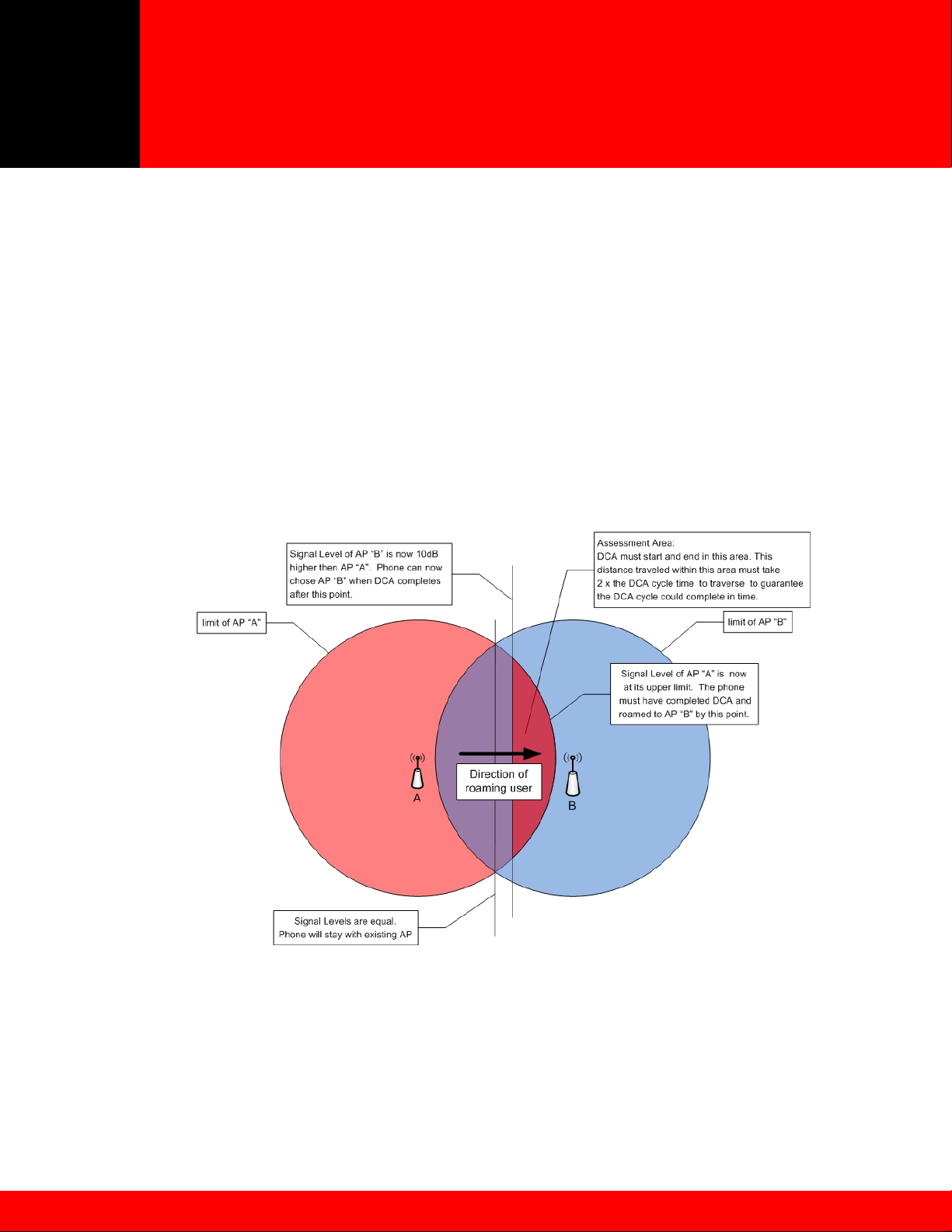
SpectraLink handsets perform Dynamic Channel Assessment (DCA) in between the transmission of
packets to learn about neighboring APs. It takes about one second for a DCA cycle to complete for a
standard three channel deployment for 802.11b. In order to ensure a DCA cycle can complete within the
assessment area (see Figure 1), a person moving through the assessment area must be within the area
for at least 4-5 seconds to make sure the DCA starts and ends within the assessment area. Failure to
complete the DCA cycle within the assessment area can lead to lost network connectivity resulting in a
hard handoff, lost audio, choppy audio or potentially a dropped call.
Figure 1 - Dynamic Channel Assessment (DCA)
The handset compares the signal strength of neighboring APs to determine whether to roam from the
current AP. In order to roam, the handset has to determine whether other APs are either five decibels
(dB) (for any first attempt associating with an AP) or ten decibels stronger (to roam back to the current
AP) than the current AP’s signal. In most cases the handset only needs five decibels of signal difference
between APs to make a decision to roam. But to prevent ‘ping-pong’ behavior the separation needs to be
©2009 Polycom, Inc. All rights reserved.
Polycom and the Polycom logo are registered trademarks of Polycom, Inc. All other trademarks are the property of Polycom, Inc. or their respective companies.
6
Page 7

Deploying SpectraLink 8020/8030
Wireless Telephones
May 2009 Best Practices Guide
ten decibels higher for the handset to return to the previously associated AP. This behavior requires that
the assessment area must have at least a ten decibel difference to enable good roaming behavior for all
cases.
Corners and doorways pose a particular design issue. The shadowing of corners can cause steep dropoffs in signal coverage. Make sure to have adequate cell overlap at and around corners so that the audio
stream is not impacted by a user going around corners. This may require placement of AP at corner
locations to ensure appropriate cover and prevent RF shadows.
2.1.2 Signal Strength
To provide reliable service, wireless networks should be engineered to deliver adequate signal strength in
all areas where the wireless telephones will be used. The required minimum signal strength for all
SpectraLink handsets depends on the data rates enabled on the AP and may also require consideration
for the 802.11 frequency band and modulation used.
Recommended signal strength characteristics are summarized in Table 1. Use these values as the
entrance signal strength of AP “A” into the assessment area for cell overlap, illustrated in Figure 1. AP
“B” should be ten decibels stronger at the coverage midpoint to allow for clean roaming handoffs.
The critical factor is the highest data rate set to “Required” or “Mandatory”
to “Supported”. The highest data rate set Mandatory determines the RF power output required by th
wireless telephone for proper operation. Broadcast frames (beacons) utilize the lowest “Basic”
while multicast frames (used for the SpectraLink i640’s push-to-talk feature and SRP handset check-ins)
use the highest data rate set Mandatory.
Referencing Table 1 the highest rate set Mandatory (Required) determines the signaling requirements for
the wireless telephone in all areas where they are used.
For example, if an 802.11b/g access point has 1Mbps, 2Mbps, 5.5Mbps and 11Mbps all set
Mandatory, the handset requires -65dBm in all areas.
For example, if an 802.11b/g access point has 1Mbps Mandatory and other rates set Supported (or
“Enabled”) the handset requires -75dBm in all areas.
Rate
(Mb/s)
Best
Practice
s (dBm)
2.4GHz 802.11b/802.11g (CCK)
1 2 5.5 11
-75 -70 -69 -65
Table 1 – 2.4GHz
1
. Other data rates can be set
e
2
data rate
1
Access Point (AP) vendors refer to this configuration setting differently but the value indicates a data rate that clients must be
capable of utilizing in order to associate with the access point. These data rates are also used for different data traffic types by
clients and APs that should be considered when designing for coverage requirements.
2
The 802.11-2007 Standard defines any data rate set as required to be basic rates. See 802.11-2007 for additional details.
(http://www.ieee.org
©2009 Polycom, Inc. All rights reserved.
Polycom and the Polycom logo are registered trademarks of Polycom, Inc. All other trademarks are the property of Polycom, Inc. or their respective companies.
)
7
Page 8

Deploying SpectraLink 8020/8030
Wireless Telephones
May 2009 Best Practices Guide
SpectraLink handsets have a Site Survey mode that can be used to validate the signal strength it is
receiving from the AP. The handset also has a Diagnostics mode which can show AP signal strength, as
well as other details, as received during a call. See the SpectraLink e340/h340/i640 Wireless Telephone
Administration Guide for details on using the Site Survey and Diagnostics mode features.
Although it is possible that SpectraLink handsets may operate at signal strengths which are weaker than
those provided in Table 1, real world deployments involve many RF propagation challenges such as
physical obstructions, interference, and multipath effects that impact both signal strength and quality.
Designing RF coverage to the required levels will provide an adequate buffer for these propagation
challenges, enabling a more reliable and consistent level of performance with low retry rates.
2.2 Access Point Configuration Considerations
There are several fundamental access point configuration options that must be considered prior to
performing a site survey and deploying a voice-capable WLAN infrastructure. In general, adjacent APs in
three dimensions (above, below and beside) must use different non-overlapping radio channels to
prevent interference between them.
This document does not cover all issues or considerations for WLAN deployment. It is strongly
recommended that Polycom Professional Service, or another suitable professional services organization,
with wireless voice deployment experience be engaged to answer additional questions about
configurations that may affect voice quality or wireless telephone performance. In addition, VIEW
Configuration Guides for WLAN infrastructure, which are available from the Polycom web site, should be
followed closely.
2.2.1 Channel Selection
The 802.11b standard provides for three non-interfering, non-overlapping frequency channels - channels
one, six and eleven in North America. Access points within range of each other should always be set to
non-interfering channels to maximize the capacity and performance of the wireless infrastructure. Figure
2 illustrates the correct deployment methodology for 802.11b deployments.
Figure 2 - 802.11b Non-interfering Channels with Overlapping Cell Coverage
©2009 Polycom, Inc. All rights reserved.
Polycom and the Polycom logo are registered trademarks of Polycom, Inc. All other trademarks are the property of Polycom, Inc. or their respective companies.
8
Page 9

Deploying SpectraLink 8020/8030
Wireless Telephones
May 2009 Best Practices Guide
If adjacent access points in three dimensions (above, below or beside) are set to the same channel, or
utilize channels with overlapping frequency bands, the resulting interference will cause a significant
reduction in the network performance and throughput, and will degrade overall voice quality. A channel
space of five MHz or greater should be used to configure neighbor APs for non-interfering channels
Figure 3 represents the 2.4 GHz frequency range, indicating the overlap in channel frequencies.
2412 2417 2422 2427 2432 2437 2442 2447 2452 2457 2464
2400 MHz
5
10
2483 MHz
4
3
2
7
9
8
1 6 11
22 MHz
Figure 3 - 802.11b Channels
.2.2 AP Transmission Power and Capacity
2
The AP transmit power should be set so that the h
as defined in Section 2.1.2 of this document. For deployments with higher AP density, lower transmit
power settings are typically required to prevent channel interference. Maximum AP power settings vary
band and by channel, and can vary between countries. Local regulations should always be checked for
regulatory compliance considerations. In addition, maximum power output levels may vary by AP
manufacturer. Where possible, all APs should be set to the same transmit power level within a give
type.
is crucial to then set the transmit power of the handset to match the transmit power of the APs for that
It
band. This will ensure a symmetrical communication link. Mismatched transmit power outputs will result
in reduced range, poor handoff, one-way audio and other quality of service or packet delivery issues.
SpectraLink Wireless Telephones support transmission power settings in the range from 5mW to 100m
(in the United States). The transmit power setting on the phone should be based on the AP’s actual EIRP
(Effective Isotropic Radiated Power) rather than the configured transmit power in the AP. Any AP
antenna gain will increase signal gain in both directions.
egardless of the selected power level settings, all APs and handsets must be configured with the same
R
settings to avoid channel conflicts or unwanted cross-channel interference. For access points that
support automatic transmission power adjustments, Polycom recommends using only static power
settings to ensure optimal performance.
mixed 802.11b/g environments, Polycom recommends configuring the transmit power of the 802.11b
In
and 802.11g radios to the same setting, if they are separately configurable. For example, set both radios
to 30mW to ensure identical coverage on both radios. For mixed 802.11a/b/g environments, where the
andsets receive the required minimum signal strength,
by
n radio
W
©2009 Polycom, Inc. All rights reserved.
Polycom and the Polycom logo are registered trademarks of Polycom, Inc. All other trademarks are the property of Polycom, Inc. or their respective companies.
9
Page 10

Deploying SpectraLink 8020/8030
Wireless Telephones
May 2009 Best Practices Guide
AP utilizes all three radios types, AP placement should first be determined by modeling for the
characteristics of 802.11a, since this environment will typically have the shortest range. Then, th
transmit power of the 802.11b and 802.11g radios should be adjusted to provide the required cove
levels and cell overlap for those networks, within the already established AP locations.
2
.2.3 Interference
Interference on a wireles
devices, cordless phones, wireless video cameras, wireless motion detectors, and rogue APs are am
the many potential interfering RF (radio frequency) sources. In general, devices that employ or emit radio
frequency signals within a given radio coverage area will have the potential to cause unwanted
interference.
adio frequency spectrum analyzers can be used to help identify the sources of such interference. Once
R
identified, interference is best mitigated by removing the interfering device(s) from the network area.
Otherwise, it may be possible to change the channel setting of the interfering device to avoid conflict w
the surrounding APs. If this is also not possible, then it may be possible to change the channel of the
surrounding APs to avoid as much radio frequency overlap with the interfering device.
documented facility-wide radio frequency usage policy will help control sources of RF energy. Ideally,
A
any RF generating device should have prior approval before introduction onto the property or installation
in any building or structures.
.2.4 Multipath and Signal Distortion
2
Multipath distortion is a form of RF interfere
between the transmitter and the receiver causing multiple signals to be detected by the receiver. This is
typically caused by the radio signal reflecting off physical barriers such as metal walls, ceilings and other
structures and is a very common problem in factories and storage environments. Multiple converging
wave fronts may be received as either an attenuated or amplified signal by the receiver. In some
instances, if the signals arrive exactly out of phase, the result is a complete cancellation of any RF
ultipath can cause severe network throughput degradation because of high error rates and packet
M
retries. This in turn can lead to severe voice quality impairment with SpectraLink Wireless Telephone
Correctly locating antennas and choosing the right type of antenna can help reduce the effects of
multipath interference.
P diversity antennas should always be used to help improve performance in a multipath environment. A
A
diversity solution uses two antennas for each radio, and will send and receive signals on the antenna
which is receiving the best signal from the wireless client. Diversity in an AP with two antennas, which
provide signaling to the same geographic area, provides a unique signal path from each antenna to the
handset. This greatly increases the probability that both the AP and the handset will receive a better
signal quality in multipath environments. Most access points support receive diversity in that they acc
the received transmission on the antenna that is getting the best signal. Some also support full transmit
diversity where the transmission is made on the same antenna that was last used to receive a signal from
that specific client. In order to provide optimal voice quality, Polycom recommends the use of APs
supporting both receive and full transmit diversity in environments where multipath is an issue. This w
help optimize the WLAN for all wireless clients. External antennas provide additional flexibility in type
(omni or directional), mounting options and gain. External antennas can be separated from 4.5 inches t
5 feet at each AP radio.
s network may originate from many sources. Microwave ovens, Bluetooth
nce that occurs when a radio signal has more than one path
e
rage
ong
ith
signal.
s.
ept
ill
o
©2009 Polycom, Inc. All rights reserved.
Polycom and the Polycom logo are registered trademarks of Polycom, Inc. All other trademarks are the property of Polycom, Inc. or their respective companies.
10
Page 11

Deploying SpectraLink 8020/8030
Wireless Telephones
May 2009 Best Practices Guide
Access point antennas should not be placed near a metal roof, wall, beam or other metal obstruction in
any environment, as this will amplify the reflection effects. Additionally, antennas should be positioned so
that they have line of sight (LoS) to most of the clients that they service. Additional instructions from the
wireless network infrastructure vendor should be followed with regard to antenna selection and placement
to provide correct diversity operation.
2.2.5 Site Surveys
A wireless RF site survey is highly recommended for any wireless network deployment. However, it is
especially critical for VoWLAN and is essential for large or complex facilities. An RF site survey can
ensure that the wireless network is optimally designed and configured to support voice by confirming RF
placement, cell overlap, channel allocation/reuse, packet transmission quality, packet retry rates, and
other deployment considerations. While many tools exist that allow customers to perform their own
assessment, Polycom recommends a professional site survey to ensure optimum coverage and minimum
interference. Polycom offers a full suite of site-survey services that will ensure a WLAN is properly
configured to support wireless voice.
To verify coverage of an installed Wi-Fi network, Polycom handsets offer a site-survey mode that can be
used to validate the AP locations and configurations are both correct and adequate. This mode detects
the four strongest AP signals and displays the signal strength along with the AP channel assignments.
The site survey mode may be used to detect areas with poor coverage or interfering channels; check for
rogue APs; confirm the Service Set Identification (SSID) and data rates of each AP and include the
security and QoS mechanisms supported by the AP; and detect some AP configuration problems. With
SpectraLink handsets, the entire coverage area must be checked to ensure that at least one access
point’s output meets the signal strength requirements summarized in Section 2.1.2 of this document. If
the site-survey mode indicates that two APs are using the same channel within range of the handset, it is
important to adjust the channelization to avoid channel conflicts.
After a site survey is complete, coverage issues can be resolved by adding and/or relocating APs if
necessary. Overlap issues may be resolved by reassigning channels or by relocating some access
points. When adjustments are made to the WLAN configuration an additional site survey or site
verification should be performed to ensure that the changes are satisfactory and have not had an adverse
impact in other areas of coverage.
2.3 Wireless Telephone Capacity
Network capacity requirements factor into the number of APs required, although in most cases the
coverage area is the primary factor. Data traffic is often very “bursty” and sporadic. This is typically
acceptable because data applications can tolerate network congestion with reduced throughput and
slower response times. Voice traffic cannot tolerate unpredictable delays, where the bandwidth
requirements are much more constant and consistent. Voice traffic can also be predicted using
probabilistic usage models, allowing a network to be designed with high confidence in meeting anticipated
voice capacity requirements. Beyond the standard IP telephony design guidelines, there are several
additional considerations that should be addressed for VoWLAN with SpectraLink handsets.
The SVP Server prevents oversubscription of an AP and improved load balancing by limiting the
maximum number of active calls per AP. Recommended settings are AP specific and can be found in the
VIEW Configuration Guides
of wireless telephones in-call on a given AP and forces handsets to handoff when capacity maximums are
reached. Overall, the calls per AP specified is often lower than the maximum number an individual AP
on the Polycom web site. The SVP Server determines the maximum number
©2009 Polycom, Inc. All rights reserved.
Polycom and the Polycom logo are registered trademarks of Polycom, Inc. All other trademarks are the property of Polycom, Inc. or their respective companies.
11
Page 12

Deploying SpectraLink 8020/8030
Wireless Telephones
May 2009 Best Practices Guide
may be able to support. This allows some telephones to work at lower rates (1Mbps and 2Mbps) and
some at the highest data rates.
2.3.1 Access Point Bandwidth Considerations
There are several factors which determine the AP bandwidth utilization during a telephone call. The first is
the VoIP protocol used and its characteristics. The type of codec utilized combined with the packet rate
will determine the size of the voice packets along with any additional overhead information required for
the protocol. Payload data will generally account for 30-50%of a typical voice packet, with 802.11 and IP
protocol overhead filling the rest. The 802.11 protocols include timing gaps for collision avoidance, which
means bandwidth utilization is more accurately quantified as a percentage of available throughput rather
than actual data throughput.
The percentage of bandwidth required is greater for lower 802.11b data rates; however it is not a linear
function because of the bandwidth consumed by the timing gaps and overhead. For example, a call using
standard 64 Kbps voice encoding (G.711) utilizes about 4.5 percent of the AP bandwidth at 11 Mbps, and
about 12 percent at 2 Mbps. In this example, four simultaneous calls on an AP would consume about 18
percent of the available bandwidth at 11 Mbps or about 48 percent at 2 Mbps or about 90 percent at
1Mbps.
The maximum number of simultaneous telephone calls an AP can support is determined by dividing the
maximum recommended bandwidth usage by the percentage of bandwidth used for each individual call.
Note that approximately 20 to 35 percent of the AP bandwidth must be reserved for channel negotiation
and association algorithms, occasional retries, and the possibility of occasional transmission rate
reductions caused by interference or other factors. Therefore, 65 to 80 percent of the total available
bandwidth should be used for calculating the maximum call capacity per AP. For example, if all calls on
an AP are using a theoretical 5.4 percent of the bandwidth at 11 Mbps, the actual number of calls
expected at that rate would be about 12 (65 percent of bandwidth available / 5.4 percent theoretical
bandwidth utilized per call). Lower overall bandwidth is available when there are a greater number of
devices associated with an AP or when lower data rates are used for the telephone call or calls.
Even with all of the known variables, there are many other vendor-specific characteristics associated with
individual APs that make it difficult to quantify the precise number of concurrent calls per AP, without
thorough testing of specific configurations. Polycom’s VIEW Configuration Guides
number of calls per AP for specific models that have been tested to be compatible with the SpectraLink
handset.
With SVP, Polycom provides the ability to limit the number of calls per AP with a configurable setting in
the SVP Server. The “Calls per Access Point” setting limits the number of active calls on each AP and can
be used to set aside bandwidth for data traffic. Wireless Telephones in-call are free to associate with
other APs within range that have not reached the set maximum number of calls. Polycom requires this
setting to be equal to or below the maximum number of calls recommended in VIEW Configuration
Guides. It is still possible for the number of phones associated to an AP to exceed the maximum number
of calls as would be the case with any additional clients associating to the same AP. The maximum
number of calls per AP will simply control how many of those associated phones will be able to enter into
a call. Additional phones beyond the maximum number specified will be forced by the SVP Server to
roam to a new AP that has not reached the maximum calls per AP. If no APs are available any phones
beyond the maximum will display an error message indicating there is insufficient bandwidth to complete
the call.
identify the maximum
©2009 Polycom, Inc. All rights reserved.
Polycom and the Polycom logo are registered trademarks of Polycom, Inc. All other trademarks are the property of Polycom, Inc. or their respective companies.
12
Page 13

Deploying SpectraLink 8020/8030
Wireless Telephones
May 2009 Best Practices Guide
2.3.2 Push-to-Talk Multicasting Considerations
SpectraLink i640 handsets provide push-to-talk (PTT) functionality using the Polycom-proprietary
SpectraLink Radio Protocol (SRP) ADPCM encoding. Because the PTT mode uses IP multicasting, all
APs on the subnet will transmit a PTT broadcast. This can be limited to only the APs that are handling
one or more PTT-enabled handsets by enabling the Internet Group Management Protocol (IGMP) on the
wired infrastructure network.
When i640 handsets are deployed on a network with newer versions of SpectraLink handsets, some
interoperability considerations must be observed. The newer SpectraLink 8030 handsets have 24 PTT
channels plus one priority channel available. SpectraLink i640 handsets have eight PTT channels with no
priority channel. When PTT is activated on a network using a mix of handset versions, only the eight
common channels will be available for the i640 handsets.
2.3.3 Telephone Usage
When the handset is used with traditional PBXs through a Telephony Gateway, the PBX interface will
assemble audio, packetize it, and release these packets at a preset interval. The PBX release interval is
generally 20ms or 30ms. The SVP Server will receive these audio packets and release them to the
network for delivery to the handset every 30ms.
With a PBX release interval of 20ms, packets delivered to the handset by the SVP Server will have one
audio payload followed by a packet with two audio payloads. This pattern, one audio payload then two
audio payloads, will continue during the call. With a PBX release interval of 30ms, packets sent to the
handset will have one audio payload each. In rare occasions, a PBX may use a 40ms release interval.
With this audio payload release interval, packets delivered to the wireless telephone will have one large
audio payload or no audio payload per packet sent to the handset. The no audio payload packets and
long time between audio (two SVP packets – 60ms) payload aggravates any weakness (multi-path, retry
packets, etc.) in the WLAN and will cause poor audio. Therefore, whenever possible the PBX should be
configured to use release intervals of 30ms or 20ms.
Because data rate and packet rates are constant with voice applications, wireless telephone calls may be
modeled in a manner very similar to circuit-switched calls. Telephone users (whether wired or wireless)
generally tend to make calls at random times and of random durations. Because of this, mathematical
models can be applied to calculate the probability of calls being blocked based on the number of call
resources available.
Telephone usage is measured in units of Erlangs. One Erlang is equivalent to the traffic generated by a
single telephone call in continuous use. A typical office telephone user will generate 0.10 to 0.15 Erlangs
of usage during normal work hours, which equates to six to nine minutes on the telephone during an
average one-hour period. Heavy telephone users may generate 0.20 to 0.30 Erlangs, or an average of 12
to 18 minutes of phone usage in an hour. Note that traffic analysis is based on the aggregate traffic for all
users, so users with higher or lower usage are included in these averages.
The traffic engineering decisions are a tradeoff between additional call resources and an increased
probability of call blocking. Call blocking is the failure of calls due to an insufficient number of call
resources being available. Typical systems are designed to a blocking level (or grade of service) of 0.5
percent to two percent at the busiest times. Traffic model equations use the aggregate traffic load,
number of users and number of call resources to determine the blocking probability. The blocking
probability can also be used along with the aggregate traffic load to determine the number of call
resources required. Traffic model equations and calculators are available at www.erlang.com.
Consider a system with APs that can support six active telephone calls. If a blocking probability of one
percent or less is desired, each AP can support approximately 13 moderate wireless telephones users. If
©2009 Polycom, Inc. All rights reserved.
Polycom and the Polycom logo are registered trademarks of Polycom, Inc. All other trademarks are the property of Polycom, Inc. or their respective companies.
13
Page 14

Deploying SpectraLink 8020/8030
Wireless Telephones
May 2009 Best Practices Guide
the AP coverage supports 12 simultaneous calls per AP, each AP can then support approximately 39
moderate users. This allows some users to be in-call and others in standby.
The Table 2 shows maximum users per AP based on the AP’s ability to handle simultaneous calls:
Areas where heavier wireless telephone usage is expected, such as cafeterias, staff lounges, and
auditoriums, can obtain higher call capacity and handle more users by installing additional APs. For most
enterprise applications however, the table above should be sufficient in demonstrating the number of
wireless handsets supported within each AP’s coverage area.
2.3.4 Telephony Gateway Capacity
Telephone system administrators should consider the user distribution on SpectraLink 8000 Telephony
Gateways much in the same way as they do PBX line cards. Telephony Gateways incorporate a physical
connection to a PBX line card. The phone system administrator should spread departments or functional
areas across multiple PBX line cards and across multiple Telephony Gateways so that a failure of either
component does not cause a complete wireless handset outage in one department or area. In addition,
system administrators must consider that one Telephony Gateway can support a maximum of eight
handsets in an active call state. While the Telephony Gateway can manage 16 wireless telephones total
only eight can be in call at any one time. Therefore, heavy users should be spread across Telephony
Gateways to reduce the chance of call blocking.
User Calling Intensity Light Moderate Heavy
Erlangs per User 0.10 0.15 0.20
Max Active Calls per
AP
1 1 1 1
2 2 2 2
3 4 3 3
4 8 6 4
5 13 9 7
6 19 13 10
7 25 17 13
8 31 21 16
9 37 25 19
10 44 30 22
11 51 34 26
12 58 39 29
Table 2 - Users Supported per Access Point
Users Supported per AP
(1% Blocking Probability)
©2009 Polycom, Inc. All rights reserved.
Polycom and the Polycom logo are registered trademarks of Polycom, Inc. All other trademarks are the property of Polycom, Inc. or their respective companies.
14
Page 15

Deploying SpectraLink 8020/8030
Wireless Telephones
May 2009 Best Practices Guide
3 Network Infrastructure Considerations
3.1 Physical Connections
SpectraLink infrastructure components, including the SVP Server(s), Telephony Gateways and OAI
Gateway, must connect to a facility’s LAN using enterprise-grade Ethernet switches rather than Ethernet
hubs or consumer-grade SOHO switches in order to provide adequate bandwidth and limit traffic collisions
and bottlenecks (see Figure 4 for reference).
Ethernet switches should be configured to statically set the speed and duplex values as appropriate for the
device being connected to that port. The SVP Server should be set to the 100Base-T/Full Full-duplex
transmission setting. This is required to support the maximum simultaneous voice calls and for optimal
system performance. The SpectraLink Telephony Gateway and OAI Gateway products utilize a 10Base-T,
half-duplex Ethernet interface and the Ethernet switch ports should be set accordingly.
Network wiring is an important component of any Ethernet-based system and is subject to local and state
building code specifications. Cat 5 or better, 4-pair 10/100 Base-T Ethernet cabling must be used for
SpectraLink infrastructure equipment.
Wireless bridges are sometimes used to interconnect geographically isolated Ethernet LANs or to extend
the range of existing WLANs. Such devices create bottlenecks for network capacity and add delay to the
overall network, which are generally not tolerable for real-time voice connections. Polycom does not
support a configuration that includes wireless bridges and does not recommend using wireless bridges
with any wireless network supporting voice.
©2009 Polycom, Inc. All rights reserved.
Polycom and the Polycom logo are registered trademarks of Polycom, Inc. All other trademarks are the property of Polycom, Inc. or their respective companies.
15
Page 16

Deploying SpectraLink 8020/8030
Wireless Telephones
May 2009 Best Practices Guide
SVP Server
Telephony Gateway
PBX
Connect to
either PBX or
call server
PSTN
Wi-Fi AP
Ethernet Switch
call server
Wi-Fi AP
WLAN Controller
TFTP Server
SpectraLink e340/h340/i640
(Download handset software)
Wireless Telephone
Figure 4 – Physi al Connections
.2 Assigning IP Addresses
3
SpectraLink handsets operate as LAN
network. IP addresses can be assigned statically through the configuration menus on the handsets or
dynamically using standard DHCP protocol. The Handset Administration Tool (HAT) can be used to qu
load and change administration options in the handsets, including static IP addresses. For dynamic IP
addressing, a DHCP server is required.
elephony Gateways and SVP Servers also require IP addresses that can be obtained by either static or
T
DHCP address assignment. It is always recommended to configure production infrastructure components
with static IP addresses to ensure consistent system access. When using one or more SVP Server(s), (see
Section 4.1.3) the Registration SVP Server must be assigned a static IP address. The Registration SVP
Server is identified by DHCP option 151 to the wireless telephones.
client devices and therefore require IP addresses to operate in the
c
ickly
©2009 Polycom, Inc. All rights reserved.
Polycom and the Polycom logo are registered trademarks of Polycom, Inc. All other trademarks are the property of Polycom, Inc. or their respective companies.
16
Page 17

Deploying SpectraLink 8020/8030
Wireless Telephones
May 2009 Best Practices Guide
When operating with an IP telephony server (IP PBX), other than Avaya or Cisco, the SVP Server also
requires a range of IP addresses that cover the total number of wireless telephones supported by that SVP
Server. That range of IP addresses is known as First Alias IP Address/Last Alias IP Address in the SVP
Server configuration menu. It is important to note that for redundancy purposes it may be necessary to
assign more IP addresses to an SVP’s Alias IP range than what the SVP Server would normally support.
Each SVP Server supports up to 500 handsets registered, but this can be limited by the total number of
Alias IP addresses configured in the SVP Server.
When a handset is using SVP and registers with the telephony server, one of the IP addresses within this
range is used to communicate between the SVP Server and the telephony server. This IP address is used
by the SVP Server as an alias to communicate with the telephony server on the wireless telephone’s behalf,
but will not be equivalent to the handset’s IP address that was either statically assigned or obtained from the
DHCP server. The range of alias IP addresses must not be used within any DHCP range or cover the IP
address used by any other device. In the case where multiple SVP Servers are used for added capacity or
redundancy, an exclusive range of IP addresses equivalent to the number of total users each SVP Server
supports is required per SVP Server. All alias IP addresses must be within the same IP subnet as the IP
address of the SVP Server they are assigned to.
3.3 Software Updates Using TFTP
All SpectraLink infrastructure components are field-upgradeable in terms of new software features and bug
fixes. SpectraLink handsets utilize a TFTP client to automatically download new code when available.
Deployments using Telephony Gateways to connect to a traditional PBX have an integrated TFTP server to
support Wireless Telephone and OAI Gateway software upgrades. However, the integrated TFTP cannot
be used to deliver software to the e340/h340/i640 wireless telephones. A network TFTP server will
simultaneously update multiple handsets, while the Telephony Gateway can only update handsets one at a
time. Therefore, in larger systems and newer deployments, a separate TFTP server should be used rather
than using the Telephony Gateway’s TFTP capability. For deployments with multiple Telephony Gateways it
is recommended to utilize an external TFTP server to centralize the management and delivery of software.
The SVP Server also requires a TFTP server for software updates. The Telephony Gateway cannot be used
as a TFTP server for the SVP Server code. Telephony Gateways receive software updates only through
FTP updates. The OAI Gateways can receive software updates via FTP as well but if software recovery
becomes necessary the OAI will utilize a TFTP server. Software updates
site.
are available from Polycom’s web
©2009 Polycom, Inc. All rights reserved.
Polycom and the Polycom logo are registered trademarks of Polycom, Inc. All other trademarks are the property of Polycom, Inc. or their respective companies.
17
Page 18

Deploying SpectraLink 8020/8030
Wireless Telephones
May 2009 Best Practices Guide
4 SpectraLink Voice Priority (SVP)
Polycom pioneered VoWLAN for the enterprise and remains the market leader today. One key success
factor has been our SpectraLink Voice Priority (SVP) mechanism for QoS. This method is proven to
deliver enterprise-grade voice quality, battery life and call capacity for SpectraLink handsets.
Quality of service (QoS) is a means of providing a level of service that will result in a network connection
of acceptable quality. Typically this results in providing different levels of service for different applications,
depending on their requirements. When data and voice are competing for bandwidth, such as in a WLAN,
it is necessary to have mechanisms to prioritize voice packets over data, preserve battery life for
handhelds, and allocate appropriate AP bandwidth for the associated device’s applications. The original
802.11 standard did not provide a QoS mechanism, so Polycom developed SVP to allow delay-sensitive
voice and asynchronous data applications to coexist on a Wi-Fi network without compromising voice
quality.
Excellent voice quality for SpectraLink handsets is ensured on a shared Wi-Fi network using SVP.
Adopted by the majority of enterprise-class WLAN vendors, SVP is well-proven and guarantees audio
quality on a shared voice and data network. SVP is compatible with 802.11 standards, but uses
proprietary methods for packet prioritization, battery management and call admission control. Access
points generally use random back-off intervals that require all types of traffic to contend for access to the
wireless medium with equal rights. However, treating all traffic equally can cause significant delays to
voice traffic. Modifying the AP behavior to recognize and prioritize voice packets increases the probability
of better performance while continuing to treat asynchronous data packets normally. The two operations
that comprise SVP in the AP, minimizing random back-off and priority queuing, require a packet-filtering
mechanism. Packet filtering requires recognizing the packet’s type. SpectraLink packets are registered
as IP protocol ID 119 at layer 4. The SVP Server performs packet delivery timing through the AP to the
wireless telephones, which is critical for ensuring seamless handoffs among APs and for enhanced
battery management. The following section offers a more detailed explanation of timed delivery.
4.1.1 SVP Infrastructure
To trigger SVP in the APs from the wired side of the network, a Telephony Gateway with integrated SVP
Server and/or a standalone SVP Server is required. Telephony Gateways can provide SVP support for
small installations with four or fewer Gateways. A SVP Server is required for applications using an IP
telephony server or using more than four Telephony Gateways.
4.1.2 SVP Server Capacity
A single SVP Server supports 120 simultaneous calls when used with Telephony Gateways or 80
simultaneous calls with an IP telephony server. Multiple SVP Servers can be used to increase capacity to
support up to 850 total calls (which can support approximately 8,000 Wireless Telephones) for IP
telephony server interfaces. When used with Telephony Gateways, the total number of users is limited to
640 (40 Telephony Gateways). For smaller IP telephony interface deployments, 10 and 20-user SVP
Servers are available. Refer to Polycom’s SpectraLink 8000 SVP Server Administration Guide
additional information regarding the maximum number of simultaneous calls and wireless telephones
supported by multiple SVP Servers.
4.1.3 Multiple SVP Servers
For installations with multiple SVP Servers, call resources are automatically allocated between the APs
and the SpectraLink Wireless Telephones by those devices’ Media Access Control (MAC) addresses. In
for
©2009 Polycom, Inc. All rights reserved.
Polycom and the Polycom logo are registered trademarks of Polycom, Inc. All other trademarks are the property of Polycom, Inc. or their respective companies.
18
Page 19

Deploying SpectraLink 8020/8030
Wireless Telephones
May 2009 Best Practices Guide
most instances, because of the large number of wireless telephones and APs expected in such an
application, the distribution of call processing will be relatively even across all SVP Servers.
Some installations with multiple SVP Servers (SVP code < 17x.033) are configured to have primary
(“master”) and one or more secondary servers. If a secondary SVP Server fails and can no longer be
detected, the packet handling will automatically be redistributed among the remaining servers. All active
calls associated to the failed secondary SVP server will be lost during this process, however the affected
wireless telephones will check-in with available SVP servers without manual reconfiguration. In the case
of a master SVP server failure, the wireless telephone system will be disrupted. To minimize downtime
related to a failed master SVP Server or a single server, it is recommended that a spare SVP Server be
readily available. The network administrator can assign the IP address of the failed unit to the
replacement SVP Server. Alternatively the number of SVP servers can be scaled to ensure that if one or
more SVP servers fail that all handsets can be allocated to the remaining SVP servers. This will require
that sufficient alias IP addresses be made available on all SVP servers to support the allocation of
additional handsets to the remaining SVP Servers.
More recent installations with multiple SVP Servers (SVP code ≥ 17x.033) use the “SVP Self Healing”
feature and do not use the Master/Slave concepts of earlier versions. There is, however, a designated
primary SVP Server, called the Registration SVP Server, that has its IP Address defined either statically
in the Wireless Telephone network configuration or acquired from DHCP option 151, thus allowing the
Wireless Telephone to initially check-in to the telephone system.
Updated handset firmware is required to take full advantage of SVP Self-Healing functionality. See Table
3 for the firmware revisions where SVP Self-Healing functionality was first introduced.
SVP ≥ 17x.033 with Handset model Handset code
Avaya 3616/3620/3626 ≥ 96.051
NEC MH110/120/140 ≥102.022
Nortel 2210/2211/2212 ≥ 97.071
SIP e340/h340/i640 ≥ 108.011
Table 3 – Handset Code Versions That Support SVP Self-Healing
The SVP Server acts as a proxy for the handset by sending and receiving packets to/from the call server
or PBX. In some IP implementations, the SVP Server also performs Network Address Translation (NAT)
for the handset. The main functions for the SVP Server to perform are indicated in Table 4.
Function SVP Server 1 (Registration) SVP Server 2
Manage handsets
©2009 Polycom, Inc. All rights reserved.
Polycom and the Polycom logo are registered trademarks of Polycom, Inc. All other trademarks are the property of Polycom, Inc. or their respective companies.
Proxy between voice platform and
handset
Send/receives all packets to/from
handset
Considered ‘home’ SVP Server Considered ‘home’ SVP Server
19
Proxy between voice platform and
handset
Send/receives all packets to/from
handset
Page 20

Deploying SpectraLink 8020/8030
Wireless Telephones
May 2009 Best Practices Guide
Manage voice packet
delivery by the AP
Limit maximum handsets in-call per
AP (static number entered by
administrator)
Receive packets from the ‘home’
SVP Server and forward to handset
though currently associated AP
Limit maximum handsets in-call per
AP (static number entered by
administrator)
Receive packets from the ‘home’
SVP Server and forward to handset
though currently associated AP
Table 4 – SVP Server Functions
The process by which the handset is able to get onto the network and register with the SVP Server and
telephony platform is a handshake process which requires multiple steps. Figure 5 is a reference followed
diagram by the step by step description of the handset and SVP Server packet handshake.
Handset 1
AP A
call server or PBX
SVP Server 1
Manages
handsets 1&2;
APs A&D
SVP Server 2
Manages
handsets 3;
APs B&C
LAN
Handset 3
AP D
Handset 2
AP B
Figure 5 – Multiple SVP Servers
Handset 1 registers with SVP Server 1
o Handset 1 always sends its packets to SVP 1
− SVP 1 forwards handset 1 packets to the call server or PBX
− The call server or PBX sends packets from the telephone this handset is in-call with
to SVP 1
− SVP 1 sends packets to the SVP managing the handset 1’s AP
o When handset 1 is using AP A (associated with) it receives packets from SVP 1
o When handset 1 is using AP B it receives packets from SVP 2
o When handset 1 is using AP C it receives packets from SVP 2
o When handset 1 is using AP D it receives packets from SVP 1
Handset 2 registers with SVP Server 1
o Handset 1 always sends its voice packets to SVP 1
− SVP 1 forwards handset 2 audio packets to the call server or PBX
− The call server or PBX sends packets from the telephone this handset is in call with
to SVP 1
− SVP 1 sends packets to the SVP managing handset 2’s AP
o When handset 2 is using AP A it receives packets from SVP 1
AP C
©2009 Polycom, Inc. All rights reserved.
Polycom and the Polycom logo are registered trademarks of Polycom, Inc. All other trademarks are the property of Polycom, Inc. or their respective companies.
20
Page 21

Deploying SpectraLink 8020/8030
Wireless Telephones
May 2009 Best Practices Guide
o When handset 2 is using AP B it receives packets from SVP 2
o When handset 2 is using AP C it receives packets from SVP 2
o When handset 2 is using AP D it receives packets from SVP 1
Handset 3 registers with SVP Server 2
o Handset 3 always sends its packets to SVP 2
− SVP 1 forwards handset 3 audio packets to the call server or PBX
− The call server or PBX sends audio packets from the telephone this handset is in call
with to SVP 2
− SVP 2 sends packets to the SVP managing handset 3’s AP
o When handset 3 is using AP A it receives packets from SVP 1
o When handset 3 is using AP D it receives packets from SVP 1
o When handset 3 is using AP E is receives packets from SVP 1
o When handset 3 is using AP F it receives packets from SVP 2
4.1.3.1 Scenario One
Scenario One assumes that the handset has registered to SVP Server 1, associated to Access Point A,
and managed by SVP Server 1 (Figure 6)
Handset communicates only to SVP Server 1 in this case
LAN
SVP Server 1
call server
or PBX
Figure 6 - Scenario One
SVP Server 2
AP A
SpectraLink
handset
4.1.3.2 Scenario Two
Scenario Two assumes that handset has roamed to Access Point B and is managed by SVP Server 2
(Figure 7)
Packets to handset (from call server or PBX) are first sent through its Home SVP Server (Server
1), then forwarded to SVP Server 2, and then transmitted by AP B to the handset
On the return trip the handset communicates back through AP B to its “Home” SVP Server
(Server 1) and back to the call server or PBX
©2009 Polycom, Inc. All rights reserved.
Polycom and the Polycom logo are registered trademarks of Polycom, Inc. All other trademarks are the property of Polycom, Inc. or their respective companies.
21
Page 22

Deploying SpectraLink 8020/8030
Wireless Telephones
May 2009 Best Practices Guide
Figure 7 - Scenario Two
Calls between handset may bypass the call server or PBX and connect directly between SVP Alias IP
addresses. Control messaging will still go to /from the call server or PBX.
As a final note, the wireless telephone learns about all available SVP Servers IP addresses when it
powers up and does the “SRP Check-In” with the Registration SVP Server (identified in DHCP option 151
or set statically). Once the handset are aware of all SVP Servers even if the Registration SVP Server
identified by DHCP option 151 goes down, the handset will still find another SVP Server to use. This is
the SVP self-healing concept in action.
Any new or replacement wireless telephones may fail to Check-In if the SVP Server identified by DHCP
option 151 is down. The new handset has not yet learned the list of all SVP Servers and does not get a
response to its Check-In Request. In this case, check the SVP Server identified by DHCP option 151 for
operational status.
Note that it is not possible to create an IP array of the SVP Servers in the DHCP option as the handset
would not understand this and would instead display “No SVP Response” on the screen. DHCP option
151 is required for the handset when it is operating with an IP protocol but is not required when the
handset is working in an Telephony Gateway environment.
When wireless telephones do the first SRP Check-In Request with the registration SVP Server, the
registration SVP will load balance the handsets across all available SVP Servers. It will tell the wireless
telephone to Check-In with another SVP Server based on a load balancing algorithm. This algorithm does
not guarantee an even distribution of handset across all SVP Servers. The wireless telephone will do an
SRP Check-In with this designated SVP Server.
Once connected to the SVP Server the handset will establish its connection to the call server or PBX,
then will become operational and be ready to make or receive calls.
4.1.4 DSCP for SVP Deployments
Quality of Service on the wired network must also be taken into consideration. With any VoIP system
there is a need for QoS to be configured from end-to-end in order to effectively ensure good audio quality
©2009 Polycom, Inc. All rights reserved.
Polycom and the Polycom logo are registered trademarks of Polycom, Inc. All other trademarks are the property of Polycom, Inc. or their respective companies.
22
Page 23

Deploying SpectraLink 8020/8030
Wireless Telephones
May 2009 Best Practices Guide
and performance. Even systems that are implemented with only voice and no data clients there is still a
need for QoS to ensure background services do not interfere with the audio.
The SVP Server is responsible for providing packet prioritization and timed release for specific time slot
deliveries to all wireless phones. Additionally, the SVP Server must have its QoS tagging configured to
use DSCP (Differentiated Services Code Point) tags that will be properly recognized by the wired and
wireless network in order to provide for low latency packet transport. There are six different DSCP tags
that can be configured in the SVP Server. It is best to always refer to the network manufacturer’s
documentation to see what DSCP tags are supported natively and which will need to be configured to
give high priority to all the of handset’s traffic. By default all SVP Server DSCP tags are set to a value of
zero or four. A valid DSCP tag range is from 0 to 63.
The SVP Server has the following DSCP tag types available:
Administration – Network administration services such as telnet and FTP
In Call – All traffic between the SVP Server and handset during an active call
Standby – All traffic between the SVP and handset during standby
RTP – All in-call audio traffic between the SVP Server and call server or PBX
PBX – All control traffic between the SVP Server and the call server or PBX
Inter-SVPII – All traffic between more than one SVP Servers
The recommended values for these traffic types should be determined by your network infrastructure
manufacturer and/or call server or PBX manufacturer. However, in most environments specific DSCP tag
values are considered to be the expected or default DSCP values.
The recommended DSCP tag values for the defined traffic types are:
Administration – Default or 0
In Call – 46
Standby – 26 (If using PTT the DSCP tag should be changed to 46)
RTP – 46
PBX – 24
Inter-SVPII – 46
All DSCP values defined here, regardless of what values are used, must be configured for appropriate
priority throughout the network to ensure end-to-end QoS functionality. It is critical that voice receive the
highest priority to ensure the user experience is as good as possible.
©2009 Polycom, Inc. All rights reserved.
Polycom and the Polycom logo are registered trademarks of Polycom, Inc. All other trademarks are the property of Polycom, Inc. or their respective companies.
23
Page 24

Deploying SpectraLink 8020/8030
Wireless Telephones
May 2009 Best Practices Guide
5 Security
Proper security provisions are critical for any enterprise Wi-Fi network. Wireless technology does not
provide any physical barrier from malicious attackers since radio waves penetrate walls and can be
monitored and accessed from outside the facility. The extent of security measures used is typically
proportional to the value of the information accessible on the network. The security risk for VoWLAN is
not limited to the typical wired telephony concerns of eavesdropping on telephone calls or making
unauthorized toll calls, but is equivalent to the security risk of the data network that connects to the APs.
Different security options are supported on SpectraLink Wireless Telephones. Determining the proper
level of security should be based on identified risks, corporate policy and an understanding of the pros
and cons of the available security methods.
5.1 Wired Equivalent Privacy (WEP)
SpectraLink Wireless Telephones support Wired Equivalent Privacy (WEP) encryption as defined by the
802.11 standard. The handsets can use either 40-bit or 128-bit key lengths. WEP is intended to provide
the same level of security over a wireless LAN as on a wired Ethernet LAN. Although security flaws have
been identified, WEP still provides strong encryption that requires an experienced and dedicated hacker
to break. While WEP is often not an acceptable option for many high security or privacy focused
enterprises, it is still useful and provides reasonable performance for voice due to the shortened key
exchange process.
5.2 Wi-Fi Protected Access (WPA) Personal, WPA2 Personal
Recognizing the need for stronger security standards beyond WEP, the IEEE developed the 802.11i
standard, which includes stronger encryption, key management, and authentication mechanisms. Wi-Fi
Protected Access (WPA) is based on draft 3.0 of the 802.11i specification and uses TKIP (Temporal Key
Integrity Protocol) encryption. WPA2 is based on the ratified 802.11i standard. The major enhancement
of WPA2 over WPA is the inclusion of the Advanced Encryption Standard (AES), which is widely
accepted as one of the most secure encryption algorithms available.
Personal mode uses a password-based authentication method called Pre-Shared Key (PSK). Personal
mode is good for time-sensitive applications such as voice, because the key exchange sequence is
limited and does not adversely affect roaming between APs. The PSK can be entered in hexadecimal or
as an ASCII passphrase from the handset’s administration menu or the HAT. The handset supports both
WPA Personal and WPA2 Personal modes.
5.2.1 Cisco Fast Secure Roaming (FSR)
Cisco’s Fast Secure Roaming (FSR) mechanism uses a combination of standards-based and proprietary
security components including Cisco Client Key Management (CCKM), LEAP authentication, Michael
message integrity check (MIC) and Temporal Key Integrity Protocol (TKIP). FSR provides strong security
measures for authentication, privacy and data integrity along with fast AP roaming on Cisco APs.
5.3 Using Virtual LANs
Virtual LANs (VLANs) can be used to segregate traffic into different security classes. By using separate
VLANs, data traffic can utilize the most robust but processing-intensive security methods. In order for
voice to operate efficiently in a WLAN, it is critical that it be separated from the data traffic by using
VLANs, mapped to WLAN SSIDs.
The 802.1Q standard establishes a method for inserting VLAN membership information into Ethernet
frames via header-information tags. SpectraLink infrastructure equipment and SVP do not generate or
©2009 Polycom, Inc. All rights reserved.
Polycom and the Polycom logo are registered trademarks of Polycom, Inc. All other trademarks are the property of Polycom, Inc. or their respective companies.
24
Page 25

Deploying SpectraLink 8020/8030
Wireless Telephones
May 2009 Best Practices Guide
forward these tags, but are otherwise compatible with 802.1Q up to the Ethernet switch ports used for the
SpectraLink equipment.
5.4 MAC Filtering and Authentication
Most access points can be configured to allow or deny association of wireless clients based on their
unique MAC address, which can be used as a method of securing the WLAN. This process generally
works well, but can cause some performance issues on some APs and is never recommended when
using voice on a WLAN.
5.5 Firewalls and Traffic Filtering
The traffic filtering capabilities of firewalls, Ethernet switches and wireless controllers can also be used as
an additional security layer if configured to allow only certain types of traffic to pass onto specific areas of
the LAN. To properly provide access control, it is necessary to understand the type of IP traffic used by
the SpectraLink handsets. When using SpectraLink Telephony Gateways to interface to a traditional PBX
or an SVP Server in an IP PBX implementation, the handset uses the SpectraLink Radio IP Protocol (ID
119).
While the SpectraLink handset will generally work through a firewall if the appropriate ports are made
available, this is never recommended. Firewalls create a great deal of jitter in the network which can
severely limit the successful, on-time delivery of audio packets to the wireless telephone. Additionally, the
use of ICMP redirects is not supported because of the extreme delay this can result when the gateway of
the SVP Server or handsets is changed dynamically. SpectraLink handset requires less than one
millisecond of jitter from the SVP Server to handset. This will be difficult to achieve if there are multiple
‘hops’ between the handset and the SVP Server.
For an IP telephony server interface, the ports used depend on the IP telephony protocol of the telephony
switch interface. The SpectraLink Wireless Telephones, Telephony Gateways and SVP Server use TCP
and UDP and other common IP protocols from time to time. These include DHCP, DNS, WINS, TFTP,
FTP, NTP, Telnet, ARP and ICMP. Polycom uses proprietary UDP channels between the infrastructure
components i.e. UDP ports 5454 - 5458. The push-to-talk (PTT) mode of the SpectraLink i640 Wireless
Telephone uses the multicast IP address 224.0.1.116, which other model handsets and SpectraLink
infrastructure components also employ to locate and maintain connection with each other. Some other
common ports between the SVP Server and call server will be RTP traffic on ports 16384 through 32767.
The port used will be chosen randomly by the phone and call server at the time of call setup.
5.6 Virtual Private Networks (VPNs)
Virtual Private Networks (VPNs) are secure, private network connections. VPNs typically employ some
combination of strong encryption, digital certificates, strong user authentication and access control to
provide maximum security to the traffic they carry. They usually provide connectivity to many devices
behind a VPN concentrator. The network can be broken into two portions - protected and unprotected:
1) The area behind the VPN server is referred to as the “protected” portion of the network. Sensitive,
private network equipment such as file servers, e-mail servers and databases reside in this portion.
2) The area in front of the VPN server is referred to as the “unprotected” network, where the wireless
APs and less sensitive network equipment often reside.
VPNs offer an extremely effective method for securing a wireless network. Many network administrators
implement VPNs to maintain the integrity of their WLANs by requiring wireless users who need access to
the protected portion of the network to connect through a VPN server.
©2009 Polycom, Inc. All rights reserved.
Polycom and the Polycom logo are registered trademarks of Polycom, Inc. All other trademarks are the property of Polycom, Inc. or their respective companies.
25
Page 26

Deploying SpectraLink 8020/8030
Wireless Telephones
May 2009 Best Practices Guide
Most voice devices, such as the SpectraLink Wireless Telephones, do not require access to the protected
portion of the network (see Figure 8). Placing the handsets, SVP Server(s) and Telephony Gateways on
the unprotected network and requiring data users to connect to the VPN ensures that the network is
protected against hackers seeking to access sensitive information within the network core.
Protected Network Core Unprotected Network
Servers
VPN Concentrator
AP
SVP Server and/or
Telephony Gateway
AP
SpectraLink
handset
Devices that require
access to the network core
utilize a secure VPN
connection (dashed line)
Figure 8 - Deploying SpectraLink Wireless Telephones with a VPN
5.7 Diagnostic Tools
The SpectraLink handset provides three comprehensive diagnostic tools to assist the administrator in
evaluating the functionality of the handsets and the surrounding wireless infrastructure. These tools are:
Run Site Survey, Diagnostics Enabled, and Syslog Mode.
Site Survey can be used to evaluate the coverage within the facility where the handsets are deployed by
testing the signal strength, or to gather information about access points regardless of the SSID.
Diagnostics Enabled is used to evaluate the overall quality of the link between the handset, access
point, and other infrastructure equipment such as IP PBX, SVP Server, and gateways. The handset’s
diagnostics are enabled through the handset admin menu and are used while the handset is in the ‘off
hook’ state.
Syslog Mode allows the handset to send various Syslog messages such as Successful and Failed
handoffs along with reason codes indicating why the handset chose to handoff to a particular AP; Call
Starts and Ends; audio statistics; and security errors. Refer to the Diagnostic Tools section of the
SpectraLink e340/h340/i640 Wireless Telephone Administration Guide for a detail explanation of
information provided by each of the Diagnostic tools.
©2009 Polycom, Inc. All rights reserved.
Polycom and the Polycom logo are registered trademarks of Polycom, Inc. All other trademarks are the property of Polycom, Inc. or their respective companies.
26
Page 27

Deploying SpectraLink 8020/8030
Wireless Telephones
May 2009 Best Practices Guide
6 Subnets, Network Performance and DHCP
Subnets are used to create a boundary between network segments. Although these boundaries are
logical, they become like a physical boundary for mobile network devices moving throughout the
enterprise. When a device with an established IP data stream (such as with an active phone call)
attempts to roam across a subnet boundary, it must obtain a valid IP address within the new subnet.
During this process, the data stream cannot be re-established automatically and the connection (voice
call) is dropped. In the case of SpectraLink Wireless Telephones, the handsets should be power cycled to
obtain a new DHCP IP address. The handsets can automatically recover in the new subnet from a lost
network connection with the original subnet, but the 40-second failure and recovery time generally
warrants cycling the power. Please note that in order for the phone to continue functioning in the new
subnet the DHCP scope must contain the appropriate DHCP options to allow the phone to regain
connectivity with the voice infrastructure.
Some APs, Ethernet switches and third-party devices have implemented methods to facilitate subnet
roaming. While these methods are transparent to the client device and are fundamentally a good
approach to accommodating multiple subnets, they often cause enough delay and jitter to manifest poor
voice quality and the tradeoffs might make such solutions unattractive for voice applications.
Since the push-to-talk feature of the SpectraLink i640 Wireless Telephones use multicast IP packets, a
PTT call will generally be isolated to a single subnet. With the deployment of IP multicast routing it is
possible for the multicast traffic that is normally pruned at the network boundary to be passed into one or
more other subnets. Please review your network manufacturer’s documentation for information on how to
properly configure multicast routing.
There are additional subnet requirements for Wireless Telephones based on the infrastructure
components that are used, as described in the following sections.
6.1 Subnets and Telephony Gateway Interfaces
SpectraLink Wireless Telephones, Telephony Gateways, SVP Server(s) and the APs generally must
reside on the same subnet. This is required because SpectraLink handsets use IP multicast messages to
initialize the handset registration on the Telephony Gateways. In addition, The Telephony Gateways and
SVP Server(s) use multicast to discover each other and stay synchronized. Most routers deployed in
multi-subnet Ethernet environments are configured to filter out multicast and broadcast messages. Unless
a router is configured for multicast routing, if a handset is powered up on a different subnet than the
Telephony Gateway to which it is registered, the multicast message will not reach the Telephony
Gateway.
6.2 Subnets and IP Telephony Server Interfaces
With an IP telephony interface, the SVP Server can be placed on a separate subnet from either the APs
or call server. The handsets will find the SVP Server and call server on another subnet through the
default gateway option statically configured in the handset or via DHCP option 3 when using a DHCP
server for IP addressing.
SpectraLink Wireless Telephones can be deployed across multiple subnets when used with an IP
telephony server if the performance requirements outlined below are met. One of two deployment
scenarios described in this section can be used, depending on needs and infrastructure capabilities. Keep
in mind that the handsets will never actively roam across a subnet boundary without power-cycling the
handsets unless a VIEW Certified layer-3 roaming infrastructure is used in accordance with the VIEW
deployment guidelines.
©2009 Polycom, Inc. All rights reserved.
Polycom and the Polycom logo are registered trademarks of Polycom, Inc. All other trademarks are the property of Polycom, Inc. or their respective companies.
27
Page 28

Deploying SpectraLink 8020/8030
Wireless Telephones
May 2009 Best Practices Guide
In one deployment scenario for accommodating multiple subnets, each subnet is treated independently
with respect to the SVP Servers and wireless network, but each subnet can still provide service to a
single IP telephony server. One or more SVP Server(s) can be deployed on each subnet just as with a
single subnet system, including identifying the registration SVP via DHCP option 151 or static
configuration. In the second scenario, a single SVP Server (or set of SVP Servers with one registration
SVP) is deployed, generally on the same subnet as the IP telephony server. The single (Registration)
SVP Server is identified to all phones via DHCP option 151 or static configuration, regardless of what
subnet the phone is operating in. This scenario requires fewer SVP Servers to be installed, but requires
higher performance from the router (see performance requirements in Section Error! Reference source
not found.).
The ability to cross a subnet boundary exists in either scenario, but the SpectraLink handsets will need to
be power cycled to obtain a new IP address within the new subnet. In addition, other configuration
considerations must be addressed. Because users will not want to re-administer the wireless telephones
to a separate subnet, Extended Service Set Identifier (ESSIDs) should be the same or the handsets
should be set to the “Learn Always” mode, the security mode and associated key should be the same or
turned off, and DHCP should be used.
6.3 Network Performance Requirements
Ethernet packets containing voice as their payload have short, useful lifetimes, making the timely delivery
of voice packets essential. Routers can introduce latency and delay between the SVP Server and the
APs, resulting in poor voice quality.
Ethernet connectivity from the call server or other voice endpoint to the SVP Server should never exceed
100 milliseconds of network delay (one way), 30 milliseconds of network jitter, and 2 percent packet loss
end-to-end, regardless of the physical properties of the link. The link from the SVP Server to the APs
should be under 100 milliseconds of network delay, one millisecond of jitter and less than two percent
packet loss. In both cases, the jitter requirements are for wired network jitter and do not include the RF
link.
One function of the SVP Server is to control the timing of packets through the AP. The SVP server
delivers audio packets to the wireless telephone every 30 millisecond. The delay between the SVP Server
and the AP needs to be controlled and consistent. Wired QoS (DSCP) is one aspect of ensuring voice
packets have highest priority. The jitter requirement between the call server and the SVP Server is a
function of how the audio is packetized for encapsulation in the SpectraLink Radio Protocol (SRP) and
the packet queuing in the SVP Server.
Jitter between the SVP Server and the AP should be measured at the wired Ethernet connection to the
AP. If the AP is a lightweight AP attached to a wireless controller and Polycom has VIEW Certified the
system, jitter can be measured at the entry to the wireless controller. However it is better to measure jitter
at the AP’s Ethernet interface if the AP does not connect directly to the wireless controller. For this
measurement, the SVP Server is delivering packets at 30 millisecond intervals with no jitter. The time is
measured from the arrival of one packet from the SVP Server directed to a single wireless telephone to
the next packet from the SVP Server to the same wireless telephone. The jitter measurement is the time
difference from the ideal 30 millisecond arrival of packets at the AP. See Figure 9.
©2009 Polycom, Inc. All rights reserved.
Polycom and the Polycom logo are registered trademarks of Polycom, Inc. All other trademarks are the property of Polycom, Inc. or their respective companies.
28
Page 29
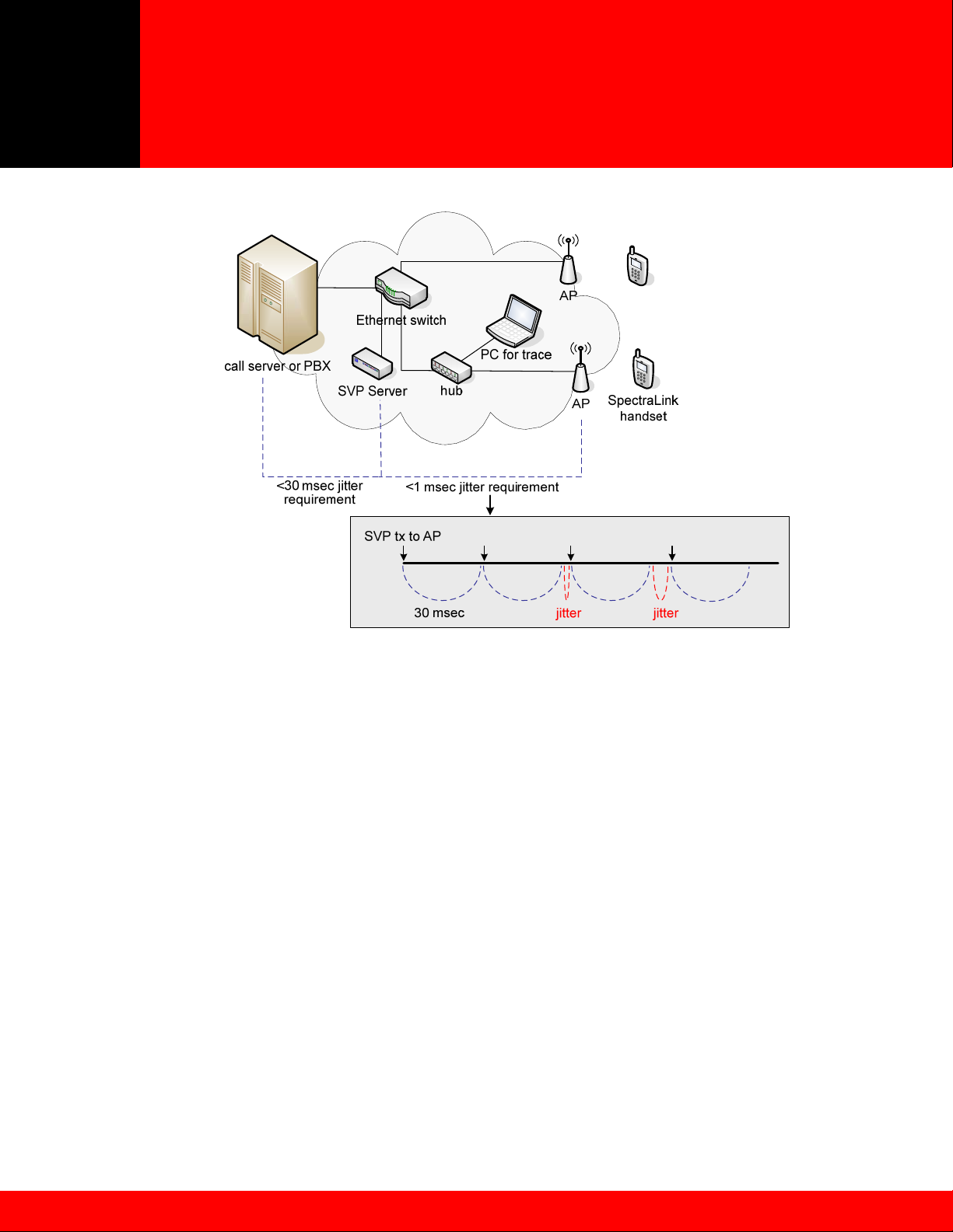
Deploying SpectraLink 8020/8030
Wireless Telephones
May 2009 Best Practices Guide
Figure 9 - Measuring Network Jitter
In a multiple SVP Server configuration, jitter is measured from the SVP Server that is responsible for the
traffic through a given AP to a wireless telephone. This may be different than the SVP Server that is
acting as a proxy for the wireless telephone to the IP PBX. Refer to Section 4.1.3 for additional multiple
SVP Server information.
SpectraLink handsets have a diagnostic option that includes jitter measurement. The calculated jitter
shown in this mode is not the jitter described above because it includes delays in the AP, radio link and
queue times inside the wireless telephone. Jitter information from the handset diagnostic mode should
only be used as a guideline for diagnosing major network or radio link problems.
6.4 DHCP Requirements
The SpectraLink Wireless Telephone is configured by default to utilize DHCP in order to obtain an IP
address and the necessary DHCP options to allow the phone to operate normally. For the different IP
protocols available with the SpectraLink handset there are a number of different DHCP options that would
be used. However, there are also a number of DHCP options that are universal required regardless of the
IP protocol implementation. Additionally, the DHCP options required for a Telephony Gateway
implementation vary somewhat from the IP protocol deployments.
Operationally, the handset functions the same regardless of the implementation when using DHCP. This
means all that is changing is the DHCP options the handset will require in order to function properly. For
Telephony Gateway deployments the handset will acquire its IP address from the DHCP server Scope
Address Pool and its Subnet mask in addition to the most basic options from the DHCP server Scope
Options. The expectation when deploying a Telephony Gateway system is that the handset will reside on
the same IP subnet as the Gateway in order to generate the necessary multicast frames that will allow it
©2009 Polycom, Inc. All rights reserved.
Polycom and the Polycom logo are registered trademarks of Polycom, Inc. All other trademarks are the property of Polycom, Inc. or their respective companies.
29
Page 30

Deploying SpectraLink 8020/8030
Wireless Telephones
May 2009 Best Practices Guide
to locate and register with the Telephony Gateway. Once the handset registers, the remaining options
that would normally be handled via DHCP, such as TFTP, are provided by the Telephony Gateway.
When the license option in the wireless phone is set for one of the IP protocols the handset will require
several other DHCP options in order to function properly. In addition to the base DHCP options required
by the Telephony Gateway implementation the handset will also require DHCP options 151 and/or 152.
Option 151 is specifically the IP address of the Registration SVP Server. Option 152 is for deployments
that are running an OAI Gateway where the option field is populated with the IP address of the OAI
gateway. These options are only accepted as IP address by the handset.
DHCP Option 66, as defined by RFC 2132, provides the address of a TFTP server. A TFTP server is
required for any SIP implementation and is only required in other IP protocols when software updates are
needed. It is recommended that a TFTP server be made available regardless of the implementation. In
SRP deployments the Telephony Gateway can act as a TFTP server but it is only capable of servicing a
single handset at a time. Additionally it is not possible to use the Telephony Gateway TFTP server to
provide software to the handsets. Because of these limitations an external TFTP server is advisable and
is often required in order to serve multiple clients at once.
Additional DHCP options are supported on the SpectraLink Wireless Telephones and can be configured
in the DHCP scope appropriate for the IP scope servicing the phones. See the Table 5 for the list of
DHCP options typically used and their purpose.
DHCP
Option
1 IP Address (i.e. 255.255.255.0) Subnet Mask
3 IP Address (i.e. 192.168.1.1) Default Gateway
6 IP Address (i.e. 192.168.1.10) DNS Server
7 IP Address (i.e. 192.168.1.20) Syslog Server
15 String (i.e. mycompany.com) Domain Name
42 IP Address (i.e. 192.168.1.30 NTP (Network Time Protocol)
66 IP Address (i.e. 192.168.1.40) TFTP Server
151 IP Address (i.e. 192.168.1.50) SVP Server
152 IP Address (i.e. 192.168.1.60) OAI Gateway
Depending on the IP protocol implementation additional DHCP options will be required to support the call
server. The options will likely include additional TFTP server addresses and the IP address of the call
server. These DHCP options should be provided by the call server manufacturer to ensure the
appropriate information and values required for those options are correct for the specific IP protocol
deployment.
While the wireless telephone does support using a DNS server, as shown in Table 5, it is not
recommended to do so. Using DNS creates a dependency on a service that may not be reliable when the
services a phone provides can be critical. By using DNS there is also the addition of latency in
transactions that the handset must complete with the DNS server which could lead to undesirable
behavior from the wireless telephone. Please note if DNS is necessary then DHCP option 15 is also
required. Without both DHCP options 6 and 15 the wireless telephone will not be able to complete DNS
queries
Value Expected Purpose
Table 5 – DHCP Options
©2009 Polycom, Inc. All rights reserved.
Polycom and the Polycom logo are registered trademarks of Polycom, Inc. All other trademarks are the property of Polycom, Inc. or their respective companies.
30
Page 31

Deploying SpectraLink 8020/8030
Wireless Telephones
May 2009 Best Practices Guide
7 Conclusion
The SpectraLink e340/h340/i640 Wireless Telephone uses Wi-Fi technology to deliver a full-featured
mobile extension to a call server or PBX. The purpose of this document is to outline the network design
criteria for a successful VoWLAN deployment. By applying the guidelines described in this document,
networking and telephony professionals can confidently design and deploy a Polycom Wi-Fi telephony
solution.
Some of the key takeaways include:
Voice and data applications have different attributes and network requirements. Several aspects
of the WLAN infrastructure, including coverage and capacity planning, require special
considerations for voice traffic.
Reliable QoS is a requirement for any enterprise voice application. Wireless VoIP is especially
vulnerable to many WLAN processes that can affect voice quality, including wireless traffic
contention and security authentication delays. SVP is proven to deliver enterprise-grade voice
quality, battery life and call capacity for SpectraLink handsets.
Several network design attributes need to be considered before deploying a VoWLAN solution,
including the use of subnets and complex network topologies that may affect the performance of
SpectraLink handsets.
Polycom’s dedication and expertise helps ensure proper deployment for VoWLAN.
Polycom Headquarters:
For North America, Latin America and Caribbean (T) +1.925.924.6000, (F) +1.925.924.6100
Polycom Wireless
Voice Communications:
©2009 Polycom, Inc. All rights reserved.
Polycom and the Polycom logo are registered trademarks of Polycom, Inc. All other trademarks are the property of Polycom, Inc. or their respective companies.
4750 Willow Road, Pleasanton, CA 94588 (T) 1.800.POLYCOM (765.9266) for North America only.
5755 Central Avenue, Boulder, CO 80301 (T) 1.800.676.5465 or +1.303.440.5330, (F) +1.303.440.5331
31
 Loading...