

Page 1
Polycom® RMX®
1500/2000/4000
Getting Started Guide for
Audio Only
Version
7.0.1
| September 2010 | DOC2579D
Page 2

Trademark Information
Polycom®, the Polycom “Triangles” logo, and the names and marks associated with Polycom’s
products are trademarks and/or service marks of Polycom, Inc., and are registered and/or
common-law marks in the United States and various other countries.
All other trademarks are the property of their respective owners.
Patent Information
The accompanying product is protected by one or more U.S. and foreign patents and/or pending
patent applications held by Polycom, Inc.
© 2010 Polycom, Inc. All rights reserved.
Polycom, Inc.
4750 Willow Road
Pleasanton, CA 94588-2708
USA
No part of this document may be reproduced or transmitted in any form or by any means,
electronic or mechanical, for any purpose, without the express written permission of Polycom, Inc.
Under the law, reproducing includes translating into another language or format.
As between the parties, Polycom, Inc., retains title to and ownership of all proprietary rights with
respect to the software contained within its products. The software is protected by United States
copyright laws and international treaty provision. Therefore, you must treat the software like any
other copyrighted material (e.g., a book or sound recording).
Every effort has been made to ensure that the information in this manual is accurate. Polycom, Inc.,
is not responsible for printing or clerical errors. Information in this document is subject to change
without notice.
Page 3

Regulatory Notices
United States Federal Communication
Commission (FCC)
Part 15: Class A Statement. This equipment has
been tested and found to comply with the limits for a
Class A digital device, pursuant to Part 15 of the FCC
Rules. Test limits are designed to provide reasonable
protection against harmful interference when the
equipment is operated in a commercial environment.
This equipment generates, uses and can radiate
radio-frequency energy and, if not installed and used
in accordance with the instruction manuals, may
cause harmful interference to radio communications.
Operation of this equipment in a residential area is
likely to cause harmful interference, in which case the
user will be required to correct the interference at his
or her own expense.
Part 68: Network Registration Number. This
equipment is registered with the FCC in accordance
with Part 68 of the FCC Rules. This equipment is
identified by the FCC registration number.
If requested, the FCC registration Number and REN
must be provided to the telephone company.
Any repairs to this equipment must be carried out by
Polycom Inc. or our designated agent. This
stipulation is required by the FCC and applies during
and after the warranty period.
United States Safety Construction Details:
• All connections are indoor only.
• Unit is intended for RESTRICTED ACCESS
LOCATION.
• Unit is to be installed in accordance with the
National Electrical Code.
• The branch circuit overcurrent protection shall
be rated 20 A for the AC system.
• This equipment has a maximum operating
ambient of 40°C, the ambient temperature in
the rack shall not exceed this temperature.
To eliminate the risk of battery explosion, the battery
should not be replaced by an incorrect type.
Dispose of used batteries according to their
instructions.
CE Mark R&TTE Directive
Polycom Inc., declares that the Polycom RMX™
2000 is in conformity with the following relevant
harmonized standards:
EN 60950-1:2001
EN 55022: 1998+A1:2000+A2:2003 class A
EN 300 386 V1.3.3: 2005
Following the provisions of the Council Directive
1999/CE on radio and telecommunication terminal
equipment and the recognition of its conformity.
Canadian Department of Communications
This Class [A] digital apparatus complies with
Canadian ICES-003.
Notice: The Industry Canada label identifies certified
equipment. This certification means that the
equipment meets telecommunication network
protective, operational and safety requirements as
prescribed in the appropriate Terminal Equipment
Technical Requirements document(s). The
Department does not guarantee the equipment will
operate to the user's satisfaction.
Before installing this equipment, users should ensure
that it is permissible to be connected to the facilities
of the local telecommunications company. The
equipment must also be installed using an acceptable
method of connection. The customer should be
aware that compliance with the above conditions may
not prevent degradation of service in some situations.
Repairs to certified equipment malfunctions, may give
the telecommunications company causes to request
the user to disconnect the equipment.
Users should ensure for their own protection that the
electrical ground connections of the power utility,
telephone lines and internal metallic water pipe
system, if present, are connected together. This
precaution may be particularly important in rural
areas.
Caution: Users should not attempt to make such
connections themselves, but should contact the
appropriate electric inspection authority, or
electrician, as appropriate.
Page 4
Regulatory Notices
Chinese Communication Certificate
RMX 2000 complies with IDA standards G0916-07
Singapore Certificate
Page 5

Polycom RMX 1500/2000/4000 Getting Started Guide for Audio Only
Table of Contents
System Overview . . . . . . . . . . . . . . . . . . . . . . . . . . . . . . 1-1
RMX 1500/2000/4000 ............................................................................ 1-1
System Capacities ................................................................................... 1-3
RMX Audio Only Main Features ......................................................... 1-6
Scheduling Interfaces ..................................................................... 1-6
Conference scheduling options .................................................... 1-6
Conferencing Modes ...................................................................... 1-6
Operator Conference .............................................................. 1-6
IVR-Enabled Conferencing ........................................................... 1-7
Entry Queue .................................................................................... 1-7
Conferencing Capabilities and Options ...................................... 1-7
On Demand Conferencing .................................................... 1-7
Scheduled Conferencing / Reservations ............................ 1-8
Polycom Conferencing for Microsoft Outlook® ................ 1-8
Connection Methods .............................................................. 1-8
Cascading Conferences .......................................................... 1-8
Gateway ................................................................................... 1-9
Security ..................................................................................... 1-9
Conference Management and Monitoring Features ............... 1-10
Application features ..................................................................... 1-10
Card Configuration Modes ................................................................. 1-11
Prerequisites .......................................................................................... 1-11
Workstation Requirements ................................................................. 1-12
Windows 7™ Security Settings .................................................. 1-12
Internet Explorer 8 Configuration .............................................. 1-15
................................................................................................................. 1-19
First Time Installation and Configuration . . . . . . . . . . . 2-1
Preparations ............................................................................................ 2-2
Gather Network Equipment and Address Information ........... 2-2
IP Services ................................................................................ 2-2
Management Network ........................................................... 2-2
Default IP Service (Conferencing Service) .......................... 2-2
IP Network Services Required Information ....................... 2-3
i
Page 6

Table of Contents
ISDN/PSTN Services ............................................................. 2-4
Unpacking the RMX ....................................................................... 2-5
Unpacking the RMX 1500 ...................................................... 2-5
Unpacking the RMX 2000 ...................................................... 2-5
Unpacking the RMX 4000 ...................................................... 2-5
Modifying the Factory Default Management Network
Settings on the USB Key ................................................................ 2-8
Hardware Installation and Setup ......................................................... 2-9
Installing the RMX 1500 ................................................................. 2-9
Mounting the RMX 1500 in a Rack .................................... 2-10
Connecting Cables on the RMX 1500 ................................. 2-11
Installing the RMX 2000 ............................................................... 2-12
Mounting the RMX 2000 in a Rack .................................... 2-12
Connecting Cables on the RMX 2000 ................................. 2-13
Installing the RMX 4000 ............................................................... 2-14
Mounting the RMX 4000 in a Rack .................................... 2-14
Connecting the RMX 4000 to the Power Sources ............. 2-15
Connecting Cables on the RMX 4000 ................................. 2-18
First Entry Power-up and Configuration .......................................... 2-19
Procedure 1: First-time Power-up .............................................. 2-19
Procedure 2: Product Registration ............................................. 2-20
Obtaining the Activation Key ............................................. 2-20
Procedure 3: Connection to MCU .............................................. 2-21
Procedure 4: Modifying the Default IP Service
and ISDN/PSTN Network Service Settings ............................. 2-22
Fast Configuration Wizard ................................................. 2-23
User Definition .............................................................................. 2-41
Selecting the RMX Web Client Languages ............................... 2-41
RMX’s Default Conferencing Settings ............................................... 2-42
Customizing the RMX’s Default Conferencing Settings ........ 2-45
Audio Only Basic Configuration and Operation . . . . . 3-1
Starting the RMX Web Client ............................................................... 3-2
RMX Web Client and RMX Manager .................................................. 3-3
RMX Web Client Screen Components ................................................. 3-4
Viewing and System Functionality Permissions ............... 3-5
Conferences List ............................................................................. 3-6
ii
Page 7

Polycom RMX 1500/2000/4000 Getting Started Guide for Audio Only
List Pane ........................................................................................... 3-7
RMX Management ......................................................................... 3-7
Status Bar ......................................................................................... 3-7
System Alerts .......................................................................... 3-8
Participant Alerts .................................................................... 3-8
Port Usage Gauges ................................................................. 3-8
MCU State ................................................................................ 3-9
Address Book ................................................................................ 3-10
Displaying and Hiding the Address Book ........................ 3-11
Conference Templates ................................................................. 3-11
Displaying and Hiding Conference Templates ................ 3-12
Customizing the Main Screen ..................................................... 3-13
Customizing the RMX Management Pane ........................ 3-14
Resource Management ........................................................................ 3-16
Resource Capacity ........................................................................ 3-16
Resource Capacity Modes ................................................... 3-17
Resource Usage - Voice Resources ..................................... 3-18
Video/Voice Port Configuration ............................................... 3-18
Flexible Resource Capacity Mode ...................................... 3-18
Fixed Resource Capacity ..................................................... 3-18
Configuring the Video/Voice Resources in
MPM, MPM+ and MPMx Modes - Flexible Resource
Capacity ................................................................................. 3-19
Resource Report ............................................................................ 3-20
Displaying the Resource Report ......................................... 3-20
Using the Default Profile, Entry Queue and Meeting Rooms ....... 3-23
Starting a Conference ........................................................................... 3-24
Starting a Conference from the Conferences Pane .................. 3-25
General Tab ........................................................................... 3-26
Participants Tab ................................................................... 3-30
Information Tab .................................................................... 3-39
Starting a Reservation .................................................................. 3-41
Starting an Ongoing Conference From a Template ................. 3-43
Starting a Video Meeting from a Microsoft Outlook
Polycom Meeting Invitation ....................................................... 3-45
Connecting to a Conference ................................................................ 3-46
Direct Dial-in ................................................................................. 3-46
iii
Page 8

Table of Contents
H.323 Participants ................................................................ 3-47
SIP Participants ..................................................................... 3-47
ISDN/PSTN Participants .................................................... 3-47
Connecting to a Polycom Conference from an Outlook
Meeting Invitation ................................................................ 3-48
Entry Queue Access ..................................................................... 3-49
H.323 Participants ................................................................ 3-49
SIP Participants ..................................................................... 3-50
ISDN and PSTN Participants .............................................. 3-50
Dial-out Participants .................................................................... 3-51
Automatic Dial Out .............................................................. 3-51
Monitoring Ongoing Conferences ..................................................... 3-52
General Monitoring ...................................................................... 3-52
Multi Selection ...................................................................... 3-53
Using the Chairperson Password for Filtering ................ 3-54
Conference Level Monitoring ..................................................... 3-54
Secured Conference Monitoring ........................................ 3-57
Monitoring Ongoing Gateway Sessions ........................... 3-57
Participant Level Monitoring ...................................................... 3-58
Participant Connection Monitoring ................................... 3-58
Operations Performed During On Going Conferences .................. 3-61
Conference Level operations ...................................................... 3-61
Changing the Duration of a Conference ........................... 3-61
Adding Participants from the Address Book ................... 3-62
Moving Participants ............................................................. 3-63
Saving an Ongoing Conference as a Template ................ 3-65
Copy and Paste Conference ................................................ 3-65
Copy Conference .................................................................. 3-65
Paste Conference ................................................................... 3-66
Paste Conference As ............................................................. 3-67
Participant Level Operations ...................................................... 3-69
Copy Cut and Paste Participant ......................................... 3-71
Copy Participant ................................................................... 3-71
Cut Participant ...................................................................... 3-72
Paste Participant ................................................................... 3-73
Paste Participant As ............................................................. 3-73
Conference Control Using DTMF Codes .................................. 3-76
iv
Page 9

Polycom RMX 1500/2000/4000 Getting Started Guide for Audio Only
Requesting Help ................................................................... 3-78
Appendix A - Glossary . . . . . . . . . . . . . . . . . . . . . . . . . A-1
v
Page 10

Table of Contents
vi
Page 11

System Overview
This Getting Started Guide provides information on the installation and
basic operation of your RMX system.
Chairpersons and Operators (users who start and manage conferences for
other users) please read:
• Chapter 1 – System Overview
• Chapter 3 – Basic Operation
System Administrators please read:
• Chapter 1 – System Overview
• Chapter 2 – First Time Installation and Configuration
• Chapter 3 – Basic Operation
For more information on configuring and managing the system, refer to
the RMX 1500/2000/4000 Administrator’s Guide included with the system.
Unless specified differently, all screen captures, Diagrams and Figures
included in this guide apply to RMX 1500, RMX 2000 and RMX 4000.
1
RMX 1500/2000/4000
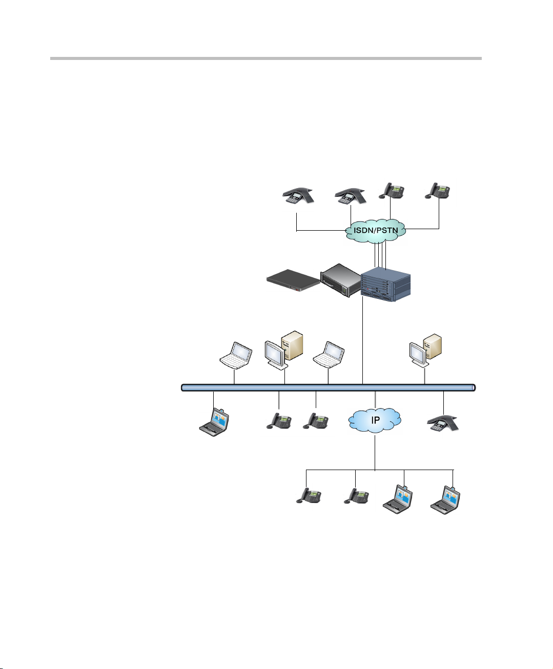
The Polycom RMX 1500/2000/4000 Multipoint Control Unit (MCU) is a
high performance, scalable, IP-network (H.323 and SIP) and ISDN/
PSTN solution that provides the user with feature-rich and easy-to-use
multipoint voice and video conferencing.
The RMX MCU meets International Telecommunication Union Telecommunication Standardization Sector, (ITU-T, formerly CCITT)
standards for multipoint multimedia bridging devices, and meets ETSI
standards for telecommunication products.
1-1
Page 12
Chapter 1-System Overview
PSTN Phones
RMX Web Client
PCIP Phone
Endpoints
E1/T1 PRI Lines
ISDN Endpoints
LAN
RMX 1500/2000/4000
The RMX unit has, in addition, been designed in compliance with IETF
(Internet Engineering Task Force) – a large open international community
of network designers, operators, vendors, and researchers concerned with
the evolution of the Internet architecture and the smooth operation of the
Internet.
Figure 1-1 Multipoint Audio Conferencing using a Polycom RMX 1500/2000/4000
1-2
Page 13
Polycom RMX 1500/2000/4000 Getting Started Guide for Audio Only
R
The Polycom RMX 1500/2000/4000 unit can be controlled via the LAN,
by the RMX Web Client application, using Internet Explorer installed on
the user’s workstation or the RMX Manager application. The RMX
Manager can control several RMX units (RMX 1500, RMX 2000 and
RMX 4000). For more information about the RMX Manager, see "RMX
Manager Application” on page 17-1.
In the RMX 1500 and RMX 2000, RMX management and IP conferencing
are performed via a single LAN port. The networks can be separated in
the Enhanced Security Environment such as DoD environment.
In the RMX 4000, RMX management and IP conferencing are performed
via two different LAN ports. The networks can be separated in the
Enhanced Security Environment.
The RMX 1500 supports one ISDN card with 4 E1/T1 PRI lines.
On the RMX 2000/4000 a maximum of two RTM ISDN cards are
supported, each providing connection for up to either 7 E1 or 9 T1 PRI
lines (E1 and T1 connections cannot be used simultaneously).
On RMX 1500/2000/4000, E1 and T1 connections cannot be used
simultaneously.
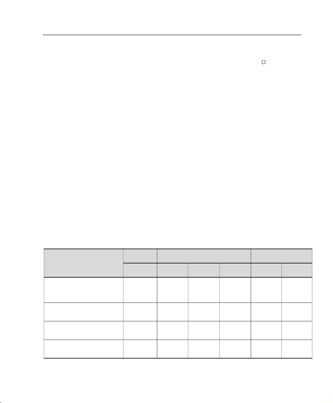
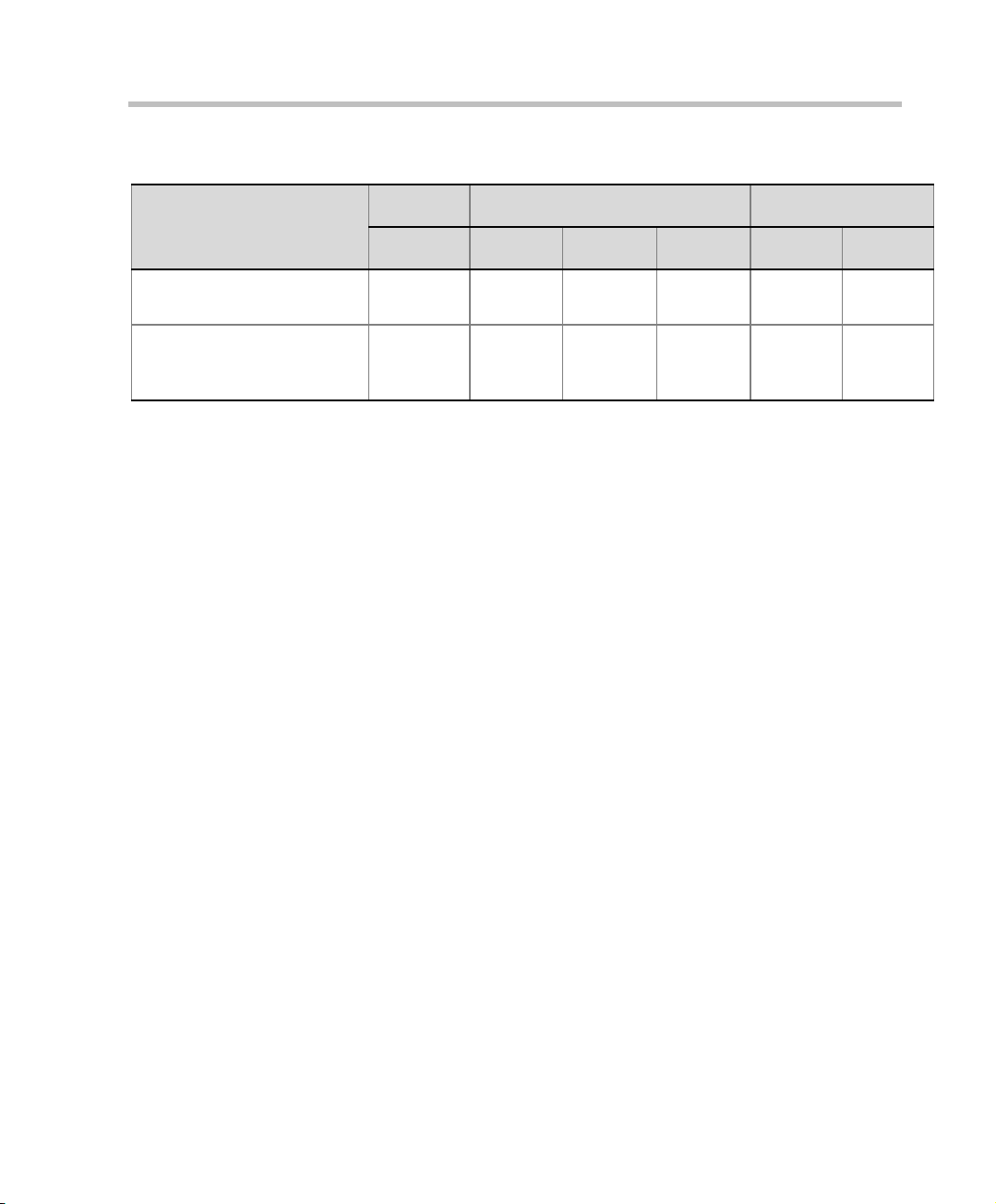
System Capacities
The following table summarizes the different conferencing capacities.
Table 1-1 System Functions and Capacities
RMX 1500 RMX 2000 RMX 4000
System Functions
MPMx MPM MPM + MPM x MPM+ MPMx
Maximum no. of VOIP (Audio
only) participants in a
conference
Maximum no. of PSTN
participants in a conference
Maximum number of
conferences
Maximum number of Meeting
Rooms
360 160 400 720 800 800
120 160 400 400 400 400
400 200 400 400 800 800
1000 1000 1000 1000 2000 2000
1-3
Page 14

Chapter 1-System Overview
Table 1-1 System Functions and Capacities (Continued)
RMX 1500 RMX 2000 RMX 4000
System Functions
MPMx MPM MPM + MPM x MPM+ MPMx
Maximum number of Entry
40 40 40 40 80 80
Queues
Maximum number of Profiles 40 40 40 40 80 80
Maximum number of
100 80 200 200 200 200
Conference Templates
Maximum number of SIP
40 40 40 40 80 80
Factories
Maximum number of IP
111111
Services
Maximum number of ISDN
222222
Services
Maximum number of IVR
40 40 40 40 80 80
Services
Maximum number of
Recording Links
Maximum number of Log
20
(default)
20
(default)
20
(default)
20
(default)
20
(default)
20
(default)
4000 1000 4000 4000 8000 8000
Files (1Mb max.)
Maximum number of CDR
2000 1000 2000 2000 4000 4000
Files
Maximum number of Fault
1000 1000 1000 1000 1000 1000
Files
Number of Participant alerts Unlimited Unlimited Unlimited Unlimited Unlimited Unlimited
Maximum number of
20 20 20 20 20 20
concurrent RMX Web Client
connections to the MCU
Maximum number Address
4000 4000 4000 4000 4000 4000
Book entries
Maximum number of Users 100 100 100 100 100 100
1-4
Page 15
Polycom RMX 1500/2000/4000 Getting Started Guide for Audio Only
Table 1-1 System Functions and Capacities (Continued)
RMX 1500 RMX 2000 RMX 4000
System Functions
MPMx MPM MPM + MPM x MPM+ MPMx
Maximum number of
gateway profiles
Maximum number of
Reservations (Internal
Scheduler)
40 40 40 40 80 80
2000 2000 2000 2000 4000 4000
1-5
Page 16

Chapter 1-System Overview
RMX Audio Only Main Features
The Polycom RMX conferencing system offers a comprehensive range of
capabilities for audio conferencing:
Scheduling Interfaces
Conferences can be started immediately or scheduled in advance on the
Polycom MCU by means of the following applications:
• Windows-based RMX Manager
• Browser-based Web Client
• Microsoft Outlook using the Polycom Conferencing for Microsoft
Outlook add-in
• Polycom CMA application
• Polycom DMA application
Conference scheduling options
• Ad Hoc conferencing
• On-demand conferencing (Ongoing)
• “Meet Me” reservationless conferences (Meeting Rooms)
• Scheduled conferences (Reservations)
• Recurrent conferences
Conferencing Modes
• Operator Assisted conferences; reserved and reservationless
• Unattended conference; reserved and reservationless
Operator Conference
In addition to the standard conference, a special conference that enables
the RMX user, acting as an operator, to assist participants without
disturbing ongoing conferences and without being heard by other
conference participants can be created. The operator can move a
participant from an Entry Queue or ongoing conference to a private, oneon-one conversation in the Operator conference.
1-6
Page 17

IVR-Enabled Conferencing
Interactive Voice Response (IVR) is a software module that automates the
connection process and lets participants perform various operations
during ongoing conferences. The participants use their endpoints’
keypads and remote control to interact with the conference’s menu-driven
scripts using DTMF codes.
Operations that can be performed by participants or chairpersons during
a conference include:
• Manually terminate the conference.
• Mute or unmute the participant’s audio channel.
• Adjust the participant’s broadcasting and listening audio volume.
• Play the Help menu.
• Mute or unmute undefined dial-in participants upon their connection
to the conference.
• Request a Roll Call and stop the Roll Call names review
• Secure and unsecure a conference.
• Request individual and conference assistance.
Polycom RMX 1500/2000/4000 Getting Started Guide for Audio Only
Entry Queue
An Entry Queue is a special routing lobby for video and audio
participants. After dialing the Entry Queue ID or dial-in number (ISDN/
PSTN), voice prompts from an IVR service are used to connect the
participants to the appropriate conference.
This service can also be used (if required) to verify the participant’s right
to start an Ad Hoc conference or to join an ongoing conference.
Conferencing Capabilities and Options
On Demand Conferencing
The following options are available to set up conferences:
• New Conference – set up once, use once.
The conference is deleted from the MCU after it ends.
1-7
Page 18

Chapter 1-System Overview
• Meeting Rooms – set up once, use many times.
Meeting Rooms are saved in memory (using no resources) and can be
activated as many times as needed.
• Ad Hoc Entry Queue – no setup, a new conference can be created when
a user dials in and enters a conference ID that is not being used by an
existing conference or Meeting Room.
• Gateway calls – from IP endpoints to other participants, using the
direct dialing method, with up to 10 destination numbers contained
in a single dial string.
Scheduled Conferencing / Reservations
Reservations provide calendar-based scheduling of single or recurring
conferences. These conferences can be launched immediately or become
ongoing, at a specified time on a specified date.
Polycom Conferencing for Microsoft Outlook®
Polycom Conferencing for Microsoft Outlook is implemented by installing the
Polycom Conferencing Add-in for Microsoft Outlook on the Microsoft Exchange
®
Server
scheduled with video endpoints from within Outlook. The add-in also
adds a Polycom Conference button in the Meeting tab of the Microsoft
Outlook e-mail client ribbon.
and Microsoft Outlook e-mail clients. It enables meetings to be
1-8
Connection Methods
IPv4, IPv6, ISDN and PSTN communication protocols are supported for
connection to the conference.
• Dial-out: automatically, to pre-defined participants (line rate
detection is automatic)
• Dial-in:
— for participants defined in advance (IP participants only)
— for undefined participants directly to a conference (IP and
ISDN/PSTN)
— for undefined participants via a single dial Entry Queue (IP and
ISDN/PSTN)
Cascading Conferences
• Simple Cascading (Star Topology).
• Multi Hierarchy Cascading (MIH).
Page 19

Polycom RMX 1500/2000/4000 Getting Started Guide for Audio Only
Gateway
Using a special Gateway Profile, the RMX can be used as a gateway that
provides connectivity across different physical networks such as H.323,
SIP, ISDN and PSTN. The Gateway also provides connectivity between
the ISDN/PSTN endpoints and the DMA.
Security
• Media Encryption (IP only), available at conference and participant
levels, based on AES 128 Media Encryption and DH 1024 Key
Exchange standards.
• Secured Communication Mode (SSL/TLS).
• Secured conferences via DTMF codes and limited monitoring of
secured conferences.
•Auditor to analyze configuration changes and unusual or malicious
activities in the RMX system.
• Network security can be enhanced by separation of the Signaling and
Management Networks.
• RMX Users can be disabled by the administrator, or automatically
when inactive. Disabled Users can be enabled by the administrator.
• Enhanced Security Environment can be implemented.
In such an environment, the following attributes are implemented:
— Password management:
• Strong Passwords and password re-use / history rules,
• password aging rules, password change frequency and
forcing password change
• Conference and Chairman Passwords
• Locking out Users
• Displaying the User Login record
— Controlling the User Sessions includes:
• Limiting the maximum number of concurrent user sessions
• Connection Timeout
• User session timeout
• Limiting the maximum number of users that can connect to
the system
1-9
Page 20

Chapter 1-System Overview
Conference Management and Monitoring Features
The Polycom RMX 1500/2000/4000 Web Client provides capabilities for
management and monitoring of participants and conferences, including
the following:
• Automatic termination of idle (no participants) conferences.
• Automatic extension of conference duration.
• Control of listening and broadcasting audio volume for individual
participants.
• Auto Gain Control (AGC) noise and audio volume regulation for
individual participants.
• Conference control via DTMF codes from participant’s endpoint or
telephone.
• Entry, exit and end-of-conference indications.
• Media encryption.
• Active display of all conferences and participants with option to limit
display in secured conferences.
• Real-time monitoring of each participant’s connection status and
properties.
• Multiple drag & drop of participants.
• Easily accessed Call Detail Records
• Active display of all system resources.
• Operator Assistance & Participant Move for conferences in
Continuous Presence mode.
Application features
• Customizable voice messages.
• Configurable new event alert.
• Easily accessible Call Detail Records (CDR) for administrator.
• Recording to an external device.
1-10
Page 21

Polycom RMX 1500/2000/4000 Getting Started Guide for Audio Only
Card Configuration Modes
Two Card Configuration Modes are supported:
• MPM Mode – Supported with MPM cards on the current, and all
previous RMX versions. Applicable to RMX 2000 only.
• MPM+ Mode – Supported from Version 4.0, with MPM+ cards
installed in the RMX 2000 and RMX 4000. It offers:
— Two Video/Voice Resource Capacity resource allocation modes for
increased control over system resource allocation.
— Enhanced Resource Report for more accurate system
management.
• MPMx Mode – Supported from Version 7.0, with MPMx cards
installed in the RMX 1500 and RMX 4000.
Prerequisites
This manual assumes the user has the following knowledge:
• Familiarity with Windows® XP or Vista® operating systems and
interface.
• Familiarity with Microsoft® Internet Explorer® Version 6 or higher.
• Basic knowledge of video conferencing concepts and terminology.
1-11
Page 22
Chapter 1-System Overview
Workstation Requirements
The RMX Web Client and RMX Manager applications can be installed in an
environment that meets the following requirements:
• Minimum Hardware – Intel® Pentium® III, 1 GHz or higher,
1024 MB RAM, 500 MB free disk space.
• Workstation Operating System – Microsoft® Windows® XP, Vista®
• Network Card – 10/100 Mbps.
• Web Browser - Microsoft® Internet Explorer® Version 6 or higher.
.Net Framework 2.0 is required and installed automatically.
If ActiveX installation is blocked please see the RMX 1500/2000/4000
Administrator’s Guide, "ActiveX Bypass” on page 18-113.
When installing the RMX Web Client, Windows Explorer >Internet Options>
Security Settings must be set to Medium or less.
Windows 7™ Security Settings
1-12
If Windows7 is installed on the workstation, Protected Mode must be
disabled before downloading the Version 7.0 software to the workstation.
To disable Protected Mode:
1 In the Internet Options dialog box, click the Security tab.
Page 23
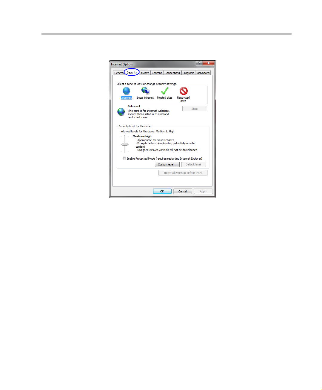
Polycom RMX 1500/2000/4000 Getting Started Guide for Audio Only
The Security tab is displayed.
1-13
Page 24
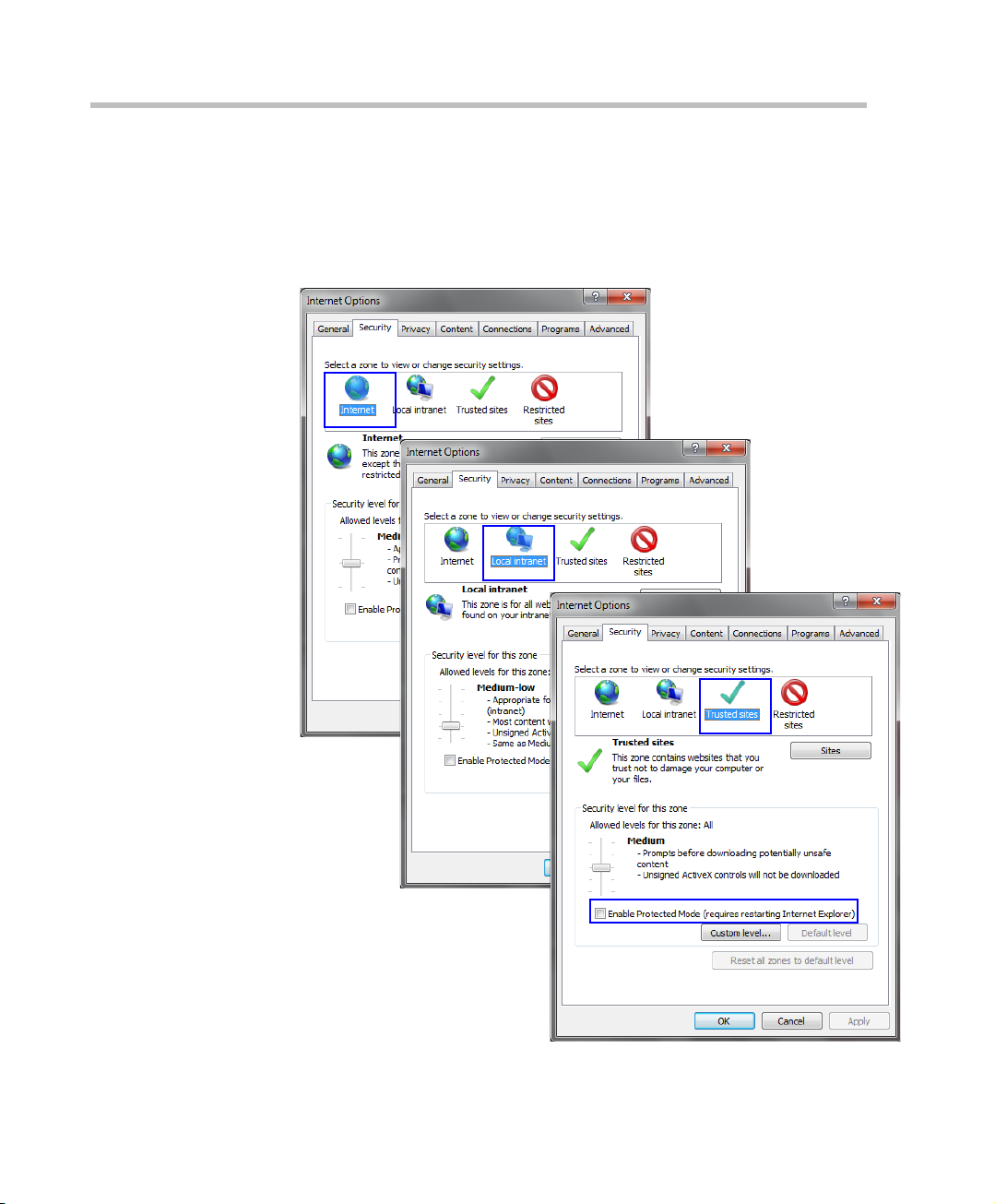
Chapter 1-System Overview
2 Clear the Enable Protected Mode check box for each of the following
tabs:
— Internet
— Local intranet
— Trusted sites
1-14
Page 25

Polycom RMX 1500/2000/4000 Getting Started Guide for Audio Only
3 After successful connection to RMX, the Enable Protected Mode check
boxes can be selected to enable Protected Mode for the following tabs:
— Internet
— Local intranet
Internet Explorer 8 Configuration
When using Internet Explorer 8 to run the RMX Web Client or RMX
Manager applications, it is important to configure the browser according
to the following procedure.
To configure Internet Explorer 8:
1 Close all browsers running on the workstation.
2 Use the Windows Task Manager to verify that no iexplore.exe processes
are running on the workstation. If any processes are found, use the
End Task button to end them.
3 Open Internet Explorer but do not connect to the RMX.
4 In the Internet Explorer menu bar select Tools >> Internet Options.
1-15
Page 26
Chapter 1-System Overview
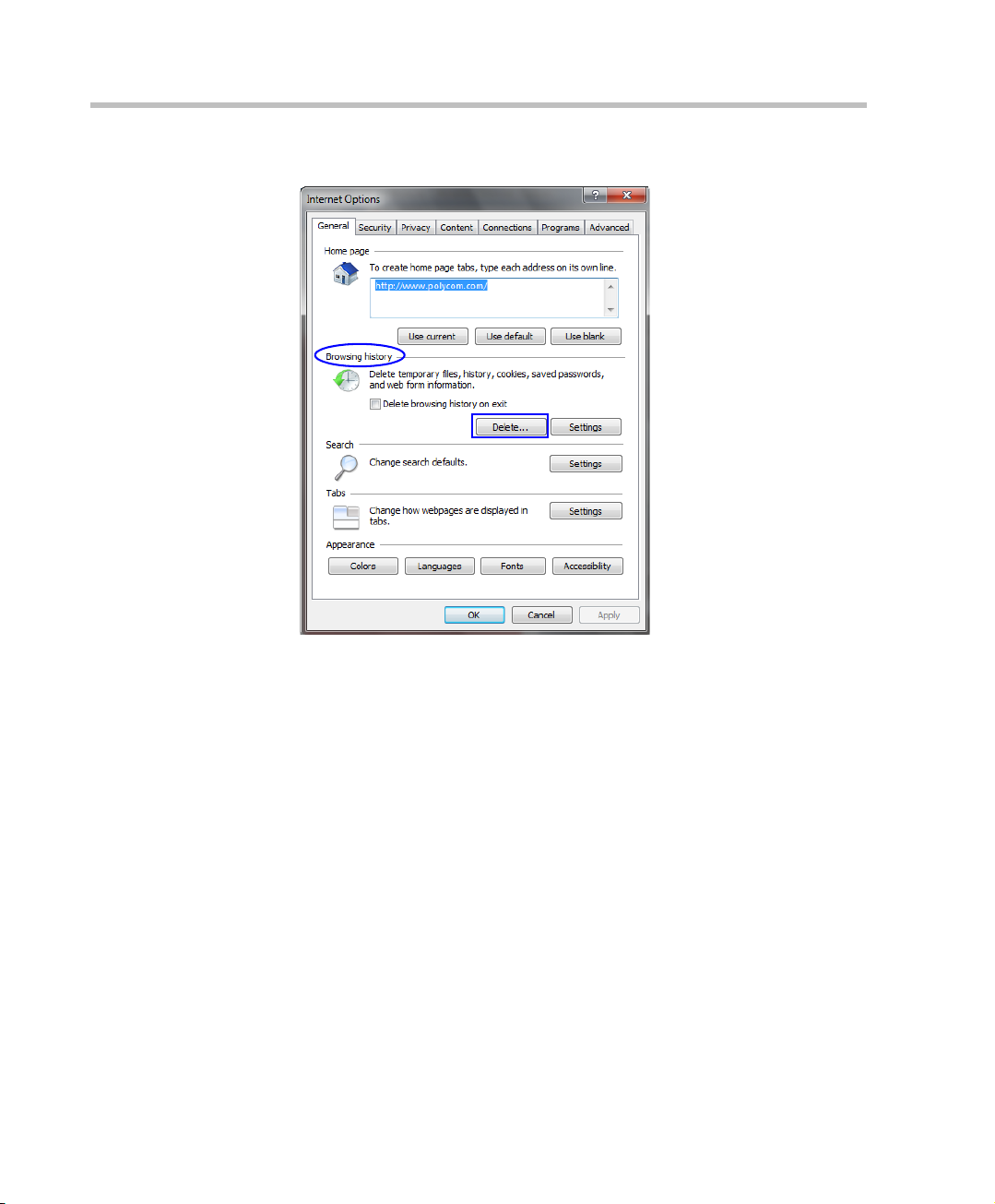
The Internet Options dialog box is displayed with General tab open.
1-16
5 In the Browsing history section, click the Delete button.
Page 27
Polycom RMX 1500/2000/4000 Getting Started Guide for Audio Only
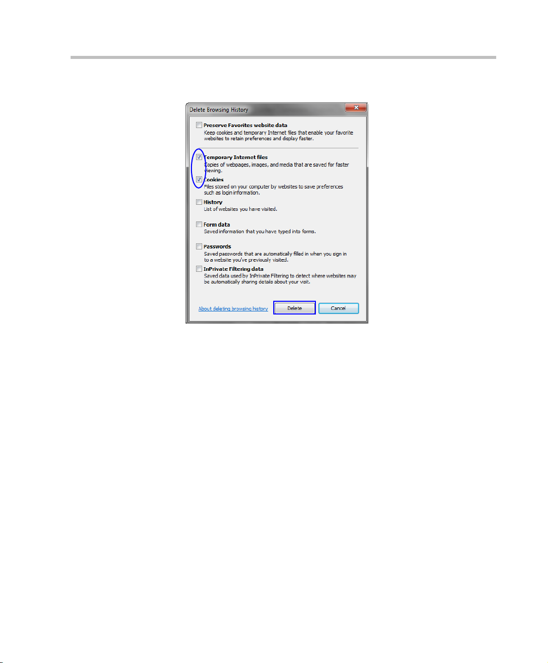
The Delete Browsing History dialog box is displayed.
6 Select the Temporary Internet files and Cookies check boxes.
7 Click the Delete button.
8 The Delete Browsing History dialog box closes and the files are deleted.
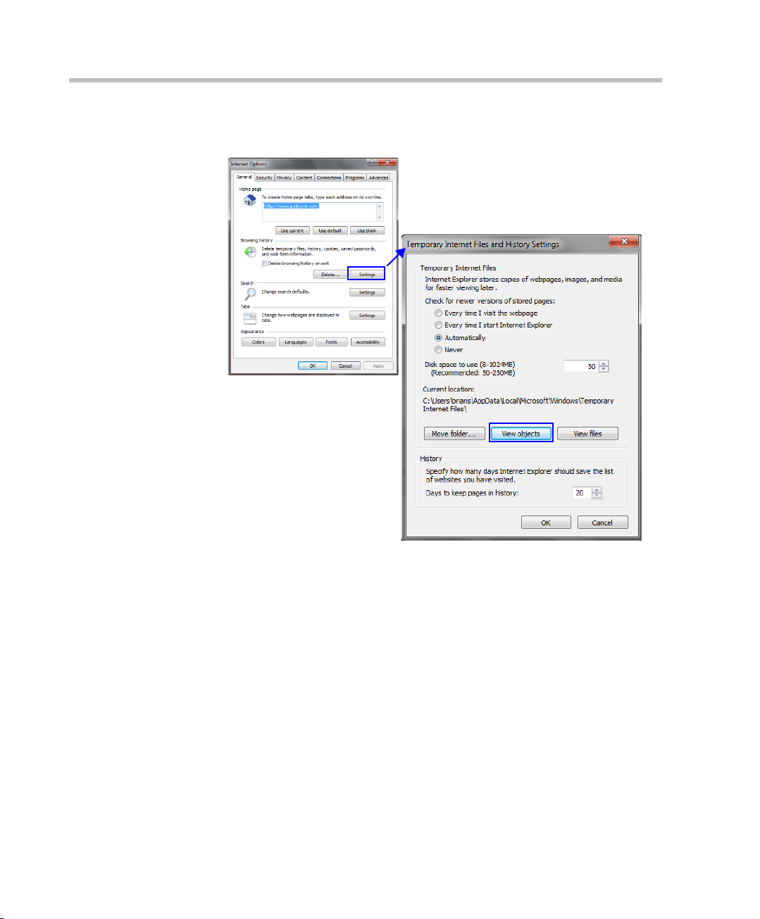
9 In the Internet Options dialog box, click the Settings button.
1-17
Page 28
Chapter 1-System Overview
The Temporary Internet Files and History Settings dialog box is
displayed.
1-18
10 Click the View objects button.
Page 29
Polycom RMX 1500/2000/4000 Getting Started Guide for Audio Only
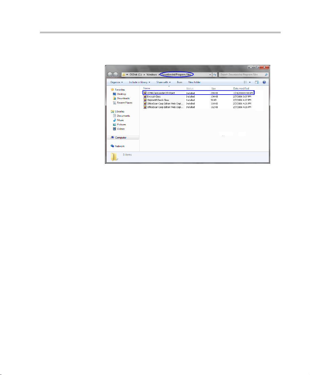
The Downloaded Program Files folder containing the installed Program
Files is displayed.
11 Select the CEMAClassLoaderCntl Object file
12 Press the Delete key on the workstation.
13 Close the Downloaded Program Files folder and the Temporary Internet
Files and History Settings dialog box.
14 In the Internet Options dialog box, click the OK button to save the
changes and close the dialog box.
1-19
Page 30

Chapter 1-System Overview
1-20
Page 31

2
Preparations
Hardware
Installation
and
Setup
First Entry
Power-up and
Configuration
First Time Installation and
Configuration
First Time Installation and Configuration of the Polycom RMX 1500/2000/4000
consists of the following procedures:
1 Preparations:
— Gather Network Equipment and Address Information - get the
information needed for integrating the RMX into the local
network.
— Unpack the RMX.
— Modify the Management Network parameters on the USB Key.
2 Hardware Installation and Setup
— Mount the RMX in a rack.
— Connect the necessary cables.
3 First Entry Power-up and Configuration
— Power up the RMX.
— Register the RMX.
— Connect to the RMX
— Configure the Default IP Network Service.
— Configure the ISDN/PSTN Network Service.
2-1
Page 32

Chapter 2-First Time Installation and Configuration
Hardware
Installation
and
Setup
First Entry
Power-up and
Configuration
Preparations
Preparations
Gather Network Equipment and Address Information
IP Services
The IP addresses and network parameters which enable communication
between the RMX, its management application and the conferencing
devices are organized in two IP services:
• Management Network (Control Unit)
• Default IP Service (Conferencing Service)
During the First Entry Configuration, the parameters of these two network
services are modified to comply with your local network settings.
Management Network
The Management Network enables communication between the RMX
Control Unit and the RMX Web Client and is used to manage the RMX.
The RMX is shipped with default IP addresses as listed in Table 2-1.
2-2
Management Network Definition
The definition of the Management Network can be done by two methods:
• USB key (recommended method) – The system is shipped with a
USB key containing the default IP addresses for the control unit and
the shelf management.
These defaults are first modified in the PC and then uploaded to the
RMX.
• Direct connection – Creating a private network between the RMX
and the computer and modifying the management network
parameters using Fast Configuration Wizard in the RMX Web Client.
For more information, see the RMX 1500/2000/4000 Administrator’s
Guide, ”Configuring Direct Connections to RMX” on page G-1.
Default IP Service (Conferencing Service)
The Default IP Service (Conferencing Service) is used to configure and
manage communications between the RMX and conferencing devices.
Page 33

Polycom RMX 1500/2000/4000 Getting Started Guide
IP Network Services Required Information
When installing an RMX unit, these default IP addresses must be
modified to your local network settings. Therefore it is important that
before powering the RMX unit up for the first time, that you obtain the
information needed to complete the Local Network Settings section of
the table from your network administrator.
For RMX 1500, the network administrator should allocate three IP
addresses in the local network for an MCU with a MPMx card.
For RMX 2000, the network administrator should allocate four IP
addresses in the local network for an MCU with one MPM/MPM+/MPMx
card and five IP addresses for an MCU with two MPM/MPM+/MPMx
cards.
For RMX 4000, the network administrator should allocate four IP
addresses in the local network for an MCU with one MPM+/MPMx card
and up to seven IP addresses for an MCU with up to four MPM+/MPMx
cards.
Table 2-1 Network Equipment and Address Information
Parameter Factory Default Local Network Settings
Control Unit
IP Address
Control Unit
Subnet Mask
Default Router IP
Address
Shelf Management IP
Address
Signaling Host IP
address
Media Board IP
address (MPM 1)
Media Board IP
address (MPM 2)
RMX 2000/4000 only
192.168.1.254
255.255.255.0
192.168.1.1
192.168.1.252
–
–
–
2-3
Page 34

Chapter 2-First Time Installation and Configuration
Table 2-1 Network Equipment and Address Information (Continued)
Parameter Factory Default Local Network Settings
Media Board IP
address (MPM 3)
RMX 4000 only
Media Board IP
address (MPM 4)
RMX 4000 only
–
–
Gatekeeper IP
address (optional)
DNS IP address
(optional)
SIP Server IP
address (optional)
–
–
–
ISDN/PSTN Services
The ISDN/PSTN Network Service is used to define the properties of the
ISDN/PSTN switch and the ISDN lines running from the ISDN/PSTN
switch to the ISDN card installed in the RMX.
Before configuring the ISDN/PSTN Network Service, obtain the
following information from your ISDN/PSTN Service Provider:
•Switch Type
• Line Coding and Framing
•Numbering Plan
•Numbering Type
• Dial-in number range
If the RMX is connected to the public ISDN Network, an external CSU or similar
equipment is needed.
2-4
Page 35

Unpacking the RMX
Unpacking the RMX 1500
To unpack and lift the RMX 1500:
1 When you receive the RMX 1500 packing case, inspect the equipment
for damage and verify that the components match the packing slip.
2 Open the top cover of the RMX 1500 packing case and make sure that
the Installation Accessories kit contains the power cables and a USB
Key.
3 Remove the top cover, lift the RMX 1500 from the package and place
it on a flat surface.
Write down the RMX’s serial number that is on a sticker on the back of the unit.
It will be needed for product registration later in the process.
Unpacking the RMX 2000
To unpack and lift the RMX 2000:
1 When you receive the RMX 2000 packing case, inspect the equipment
for damage and verify that the components match the packing slip.
2 Open the top cover of the RMX 2000 packing case and make sure that
the Installation Accessories kit contains the power cables and a USB
Key.
3 Remove the top cover, lift the RMX 2000 from the package and place
it on a flat surface.
Polycom RMX 1500/2000/4000 Getting Started Guide
Write down the RMX’s serial number that is on a sticker on the back of the unit.
It will be needed for product registration later in the process.
Unpacking the RMX 4000
To unpack and lift the RMX 4000:
1 When you receive the RMX 4000 packing case, inspect the equipment
for damage and verify that the components match the packing slip.
2 The RMX 4000 is shipped in a packing case with Stratocell®
packaging, and the top cover must be unlocked and lifted.
3 Open the top cover of the packing case.
2-5
Page 36

Chapter 2-First Time Installation and Configuration
Two boxes are placed on the top Stratocell®, labelled:
— Installation Accessories. This kit contains the power cables and a
Disk-on Key (DOK).
— Rack Installation Accessories. This kit contains the accessories for
the 19” & 23” racks as follows:
Table 2-2 19” & 23” Rack Installation Accessories Package
Item ID Description Quantity
MEC2474A-L0 Chassis runner for rack installation
on the RMX 4000. 19” & 23” racks
both require that these runners be
installed on the rack.
MEC2475A-L0 23" bracket to be fitted to the front of
the RMX 4000.
Make sure that boxes contain all the required parts.
2
2
2-6
Page 37

Polycom RMX 1500/2000/4000 Getting Started Guide
4 Remove the boxes and top Stratocell® and open the anti-static plastic
bag wrapping the RMX.
5 Holding the handle on each side, lift the RMX 4000 from the box, and
place it on a flat surface or in a rack. Remove any packaging material
prior to positioning the RMX 4000.
Attention:
Two people are required to lift the MCU out of the box and when installing it in a
rack.
Write down the RMX’s serial number that is on a sticker on the back of the unit.
It will be needed for product registration later in the process.
2-7
Page 38

Chapter 2-First Time Installation and Configuration
Modifying the Factory Default Management Network
Settings on the USB Key
The USB key contains a text file, lan.cfg, which holds the factory default IP
address parameters. These parameters must be modified to your local
network settings using the LAN Configuration Utility, also on the USB key.
To modify the USB key settings:
1 Take the USB Key from the Installation Accessories kit and insert it into
the PC workstation and double-click LanConfigUtility.exe to start
the utility.
The LAN Configuration Utility dialog box opens.
2-8
2 Modify the following parameters in the utility’s dialog box using the
information supplied by your network administrator.
— Control Unit IP Address
— Shelf Management IP Address
— Subnet Mask
— Default Router IP Address
3 Click OK.
4 Remove the USB Key from the PC.
The USB key is required for first entry power-up.
Page 39

Polycom RMX 1500/2000/4000 Getting Started Guide
Hardware Installation and Setup
The RMX 1500/RMX 2000 unit should be mounted in a 19”rack in a well
ventilated area. The RMX 4000 unit can be mounted in a 19” or 23”rack in
a well ventilated area. It is important to adhere to the Site Requirements as
described in the RMX 1500 & RMX 1500/2000/4000 Hardware Guides, ”Site
Requirements” on page 1-3.
Installing the RMX 1500
For detailed instructions, precautions and requirements for installing the RMX
1500 refer to the Polycom RMX 1500 Hardware Guide.
The following procedures have to be performed to install the RMX 1500 in
your site:
• Installing the RMX in a rack or as a standalone
• Connecting the RMX 1500 to the power source
• Connecting the network (LAN, IP and ISDN) cables to the RMX.
2-9
Page 40

Chapter 2-First Time Installation and Configuration
Mounting the RMX 1500 in a Rack
There are two methods for installing the RMX in a 19” rack:
• Using rack brackets on the RMX 1500– Install rack brackets,
supplied by the rack manufacturer, in the rack. Mount the RMX 1500
on top of the rack brackets. Fasten the RMX to the rack with screws
through the four holes in the RMX’s front mounting brackets.
2-10
• Using a shelf – Install the shelf, supplied by the rack manufacturer,
in the rack. Mount the RMX on the shelf. Fasten the RMX to the rack
with screws through the four holes in the RMX’s front mounting
brackets.
Page 41

Polycom RMX 1500/2000/4000 Getting Started Guide
E1/T1 PRI
Connection(s)
Power Cable
LAN 2; media, MNG; signaling,
MNGB; management & Shelf
Connecting Cables on the RMX 1500
To connect the cables:
•For the RTM-IP 1500 module:
— Connect the Media cable to LAN 2 port.
— Connect the Network cables to the MNG (Signaling) port &
MNGB (Management Network) port.
— (Optional) Connect the Shelf Management cable to the Shelf port.
•For the RTM ISDN 1500 module:
— Connect the E1/T1 cables to their PRI (1-4) ports.
Figure 2-1 RMX 4000 Rear Panel View with AC Power and Communication
Cables
The LAN 1, LAN3, LAN4 and Modem ports are not be used and the plastic caps
covering those ports should not be removed.
2-11
Page 42

Chapter 2-First Time Installation and Configuration
Installing the RMX 2000
For detailed instructions, precautions and requirements for installing the RMX
2000 refer to the Polycom RMX 2000 Hardware Guide.
• The following procedures have to be performed to install the RMX
2000 in your site:
• Installing the RMX in a rack or as a standalone
• Connecting the RMX 2000 to the power source
• Connecting the network (LAN, IP and ISDN) cables to the RMX
Mounting the RMX 2000 in a Rack
There are two methods for installing the RMX in a 19” rack:
• Using rack brackets on the RMX 2000– Install rack brackets,
supplied by the rack manufacturer, in the rack. Mount the RMX 2000
on top of the rack brackets. Fasten the RMX to the rack with screws
through the four holes in the RMX’s front mounting brackets.
2-12
• Using a shelf – Install the shelf, supplied by the rack manufacturer,
in the rack. Mount the RMX on the shelf. Fasten the RMX to the rack
with screws through the four holes in the RMX’s front mounting
brackets.
Page 43

Polycom RMX 1500/2000/4000 Getting Started Guide
Power
Cable
E1/T1 PRI Connection
LAN 2 Connection
Connecting Cables on the RMX 2000
Do not remove the protective caps from LAN1, LAN3 and ShMG ports.
Connect the following cables to the back panel:
•Power cable
•LAN cable to LAN 2 Port
•E1/T1 Cables to PRI Ports
To maximize conferencing performance, especially in high bit rate call
environments, a 1Gb connection is recommended.
2-13
Page 44

Chapter 2-First Time Installation and Configuration
Installing the RMX 4000
The following procedures have to be performed to install the RMX 4000 in
your site:
• Mounting the RMX in a rack
• Connecting the RMX 4000 to the power source
• Connecting the network (LAN, IP and ISDN) cables to the RMX
Mounting the RMX 4000 in a Rack
Either place the RMX 4000 on a hard, flat surface such as a desktop or
mount it on a 19”/23” rack.
For a detailed description of the safety requirements and precautions and the
installation of the RMX 4000 as a standalone, in a 23” rack, or reverse mounting
the RMX 4000 on a 19” rack, see the RMX 4000 Hardware Guide.
To install the RMX 4000 in a 19”rack:
• Using rack brackets on the RMX 4000
— Install chassis runners supplied by Polycom, in the rack.
— Mount the RMX 4000 on top of the rack brackets.
— Fasten the RMX to the rack with screws through the eight holes
in the RMX’s front mounting brackets.
• Using a shelf
— Install the shelf, supplied by the rack manufacturer, in the rack.
— Mount the RMX on the shelf.
— Fasten the RMX to the rack with screws through the four holes in
the RMX’s front mounting brackets.
2-14
Page 45

Polycom RMX 1500/2000/4000 Getting Started Guide
Power Cables
Connecting the RMX 4000 to the Power Sources
The size of the protective earthing conductor & cable should be a minimum of
10AWG.
Connect the following power cables to the RMX 4000 back panel:
AC Power Supply connections:
1 Insert power cables to each of the three AC Power Entry Modules
(PEMs).
Figure 2-2 RMX 4000 Rear Panel View with AC Power
DC Power Supply connections:
1 On the DC Power Rail Modules set the two circuit breakers to OFF.
Two types of circuit breakers can be installed on the DC Power Rail Module
(PRM). For more information, see the RMX 4000 Hardware Guide.
2 Ensure that the cables from the Main that supplies electricity to the
DC power units are OFF or disconnected.
2-15
Page 46

Chapter 2-First Time Installation and Configuration
ESD connector
Circuit breaker - ON
position
-48 VDC
RTN
Ground connector
Blank panel
Circuit breaker - OFF
position
3 Remove the transparent plastic caps on the terminal block.
4 Using the two wires of an 10 AWG cable running from the DC power
distribution unit, connect the black wire into the -48VDC terminal
block and the red wire to the RTN terminal block.
• A 10 AWG cable must be used to connect the mains with the RMX 4000 DC
Power Rail Model.
• The supply wires for DC version must be terminated using quick connectors.
• Extension cords may not be used.
2-16
The center PRM slot/module is fitted with a blank panel and the slot cannot be
used on a system with DC Voltage.
5 Connect the green or green-yellow wire to the system single-point
M6x15 “Ground” bolt.
The rating of the protective earthing conductor should be a minimum of 10AWG.
Page 47

Polycom RMX 1500/2000/4000 Getting Started Guide
If the unit is rack mounted, the single-point ground on the MCU must
be connected to the rack with a single conductor and fixed as to
prevent loosening. When using bare conductors, they must be coated
with an appropriate antioxidant compound before crimp connections
are made. Tinned, solder-plated or silver plated connectors do not
have to be prepared in this manner.
6 Replace the transparent plastic caps on the terminal block.
7 Turn ON the Main that supplies power to the RMX.
8 Turn ON the circuit breaker on each of the DC Power Rail Modules.
2-17
Page 48

Chapter 2-First Time Installation and Configuration
LAN Connections to RTM LAN
Power Cables
Off/On
switch
E1/T1 Connection to RTM ISDN
Shelf
Management
Management
Network
Signalling
Network
Connecting Cables on the RMX 4000
To connect the cables (AC and DC systems):
• RTM-IP 4000:
— Connect the Management Network cable to LAN 2.
— Connect the Signalling cable to LAN 3.
— Connect the Shelf Management cable to LAN 6.
•For each installed RTM LAN - Connect the LAN cable to LAN 2.
•For each installed RTM ISDN:
— Connect the E1/T1 cables to their PRI Ports.
— Connect the LAN cable to LAN 1.
2-18
Figure 2-3 RMX 4000 Rear Panel View with AC Power and Communication
Cables
Page 49

Polycom RMX 1500/2000/4000 Getting Started Guide
Preparations
Hardware
Installation
and
Setup
First Entry
Power-up and
Configuration
First Entry Power-up and Configuration
There are four procedures necessary for setup of the new RMX. It is
important that they are performed in the following sequence:
1 First-time Power-up
2 Product Registration.
3 Connection to MCU.
4 Modifying the Default IP and ISDN/PSTN Service Settings (Fast
Configuration Wizard).
Procedure 1: First-time Power-up
To power-up for the first time using the USB key:
1 Insert the USB key containing the modified IP addresses in USB port
on the RMX 1500 front panel and RMX 2000/4000 back panel.
2-19
Page 50

Chapter 2-First Time Installation and Configuration
2 Power the RMX On.
AC System - Turn ON the power by pressing on the power switch
located on the rear panel of the RMX 1500/2000/4000.
DC System (RMX 4000) - Turn ON the Main that supplies power to
the RMX and then turn ON each of the DC power rail modules.
The parameters in the lan.cfg file are uploaded from the USB key to
the RMX’s memory and applied during the power-up sequence.
System power-up sequence may take up to five minutes.
During the First-time Power-up the red ERR LED on the RMX’s front
panel remains ON until both the Management and IP Network Services
have been defined.
When the RMX's configuration is completed (including the
Management and IP Network Services), and if there are no System
Errors, the green RDY LED on the CNTL module (on the RMX’s front
panel) turns ON.
3 Remove the USB key.
Procedure 2: Product Registration
2-20
Before the RMX can be used, it is necessary to register the product and
obtain an Activation Key.
During first-time power-up, the Product Activation dialog box is displayed,
requesting you to enter an Activation Key.
Obtaining the Activation Key
1 Access the Service & Support page of the Polycom website at:
http://support.polycom.com
2 Login with your Email Address and Password or register as a new user.
3 Select Product Registration.
4 Follow the on-screen instructions for Product Registration and Product
Activation. (The RMX’s serial number is on a sticker on the back of the
unit, if needed.)
5 When the Product Activation Key is displayed, write it down or copy it
for later pasting into the Activation Key field of the Product Activation
dialog box.
Page 51

Procedure 3: Connection to MCU
If Windows7™ is installed on the workstation, Protected Mode must be
disabled before connecting to the MCU running Version 6.0 software.
For more information see ”Windows 7™ Security Settings” on page 1-12.
1 Start the RMX Web Client application on the workstation.
a In the browser’s address line, enter the IP address of the Control
Unit in the format:
defined in the USB key.
b Press Enter.
The RMX Web Client Login screen is displayed.
2 In the RMX Web Client Login screen, enter the default Username
(POLYCOM) and Password (POLYCOM) and click Login.
The RMX Web Client opens and the Product Activation dialog box
appears with the serial number filled in:
http://<Control Unit IP Address>, as
Polycom RMX 1500/2000/4000 Getting Started Guide
3 In the Activation Key field, enter or paste the Product Activation Key
obtained earlier.
4 Click OK.
As no Default IP Network Service is defined, the system automatically
starts the Fast Configuration Wizard.
2-21
Page 52

Chapter 2-First Time Installation and Configuration
Procedure 4: Modifying the Default IP Service and ISDN/
PSTN Network Service Settings
The Fast Configuration Wizard assists in configuring the Signaling Network
Service. It starts automatically if no Signaling Network Service is defined.
This happens during First Time Power-up, before the service has been
defined or if the Signaling Service has been deleted, followed by an RMX
restart.
The IP Management Service tab in the Fast Configuration Wizard is enabled
only if the factory default Management IP addresses were not modified.
On the RMX 1500, RMX 2000 and RMX 4000, IPv4 is the default protocol for
setting the Network Service in the Fast Configuration Wizard.
If IPv6 addressing is required, complete the Fast Configuration Wizard and
then:
1 Modify the Management Network to use IPv6 addressing or IPv4 and IPv6
addressing.
2 Restart the RMX.
3 Use the Fast Configuration Wizard which will now include IPv6 addressing
or IPv4 & IPv6 addressing options to configure the Signaling Network
Service.
For detailed description of the IP Network Services, see the RMX 1500/2000/
4000 Administrator’s Guide.
2-22
Page 53

Polycom RMX 1500/2000/4000 Getting Started Guide
RMX 1500
RMX 4000
RMX 2000
Fast Configuration Wizard
1 Enter the required IP information in the dialog box.
2-23
Page 54

Chapter 2-First Time Installation and Configuration
Table 2-3 Fast Configuration Wizard – IP Signaling
Field Description
Network Service
Name
Signaling Host
IP Address
Media Card 1-4
IP Addresses
Subnet Mask Enter the subnet mask of the MCU.
If Secured Communication is required on the RMX: complete the Fast
Configuration Wizard, Login, install the Certificate and then enable Secured
Communication Mode.
The name Default IP Service is assigned to the IP
Network Service by the Fast Configuration Wizard.
This name can be changed.
Note: This field is displayed in all IP Signaling dialog
boxes and can contain character sets that use
Unicode encoding.
Enter the address to be used by IP endpoints when
dialing in to the MCU.
Dial out calls from the RMX are initiated from this
address.
This address is used to register the RMX with a
Gatekeeper or a SIP Proxy server.
Enter the IP address(es) of the media card (s)
(MPM/MPM+/MPMx 1 and MPM/MPM+/MPMx 2-4
(if installed)) as provided by the network
administrator. Endpoints connect to conferences
and transmit call media (video, voice and content)
via these addresses.
Default value: 255.255.255.0.
2-24
2 Click Next.
Page 55

Polycom RMX 1500/2000/4000 Getting Started Guide
3 Enter the required Routers information in the dialog box.
Table 2-4 Fast Configuration Wizard – Routers
Field Description
Default Router
IP Address
4 Click Next.
Enter the IP address of the default router.
2-25
Page 56

Chapter 2-First Time Installation and Configuration
5 Enter the required DNS information in the dialog box.
Table 2-5 Fast Configuration Wizard – DNS
Field Description
2-26
MCU Host Name Enter the name of the MCU on the network.
Default name is RMX.
DNS Select:
• Off – if DNS servers are not used in the network.
• Specify – to enter the IP addresses of the DNS
servers.
Note: The IP address fields are enabled only if
Specify is selected.
Register Host
Names
Automatically to
DNS Server
Local Domain
Name
Primary DNS
Server IP Address
Select this option to automatically register the MCU
Signaling Host and Shelf Management with the DNS
server.
Enter the name of the domain where the MCU is
installed.
The static IP address of the primary DNS server.
Page 57

Polycom RMX 1500/2000/4000 Getting Started Guide
6 Click Next.
7 Select the IP Network Type: H.323, SIP or H.323 & SIP.
8 Click Next.
9 If you selected SIP only, go to Step 13.
10 Enter the required Gatekeeper information in the dialog box.
2-27
Page 58

Chapter 2-First Time Installation and Configuration
Table 2-6 Fast Configuration Wizard – Gatekeeper
Field Description
Gatekeeper Select Specify to enable configuration of the
Primary Gatekeeper
gatekeeper IP address.
When Off is selected, all gatekeeper options are
disabled.
IP Address or
Name
MCU Prefix in
Gatekeeper
Aliases
Alias The alias that identifies the RMX’s Signaling Host
Type The type defines the format in which the card’s alias
Enter either the gatekeeper’s host name (if a DNS
Server is used) or IP address.
Enter the string with which the MCU registers itself
with the gatekeeper.
The gatekeeper uses this string to identify the MCU
when forwarding calls to it.
H.323 endpoints use this number as the first part of
their dial-in string when dialing the MCU.
within the network. Up to five aliases can be defined
for each RMX.
Note: When a gatekeeper is specified, at least one
prefix or alias must be entered in the table.
is sent to the gatekeeper. Each alias can be of a
different type:
• H.323 ID (alphanumeric ID)
• E.164 (digits 0-9, * and #)
• Email ID (email address format,
e.g. abc@example.com)
• Participant Number (digits 0-9, * and #)
Note: Although all types are supported, the type of
alias to be used depends on the gatekeeper’s
capabilities.
2-28
11 Click Next.
12 If you selected H.323 only, go to Step 15.
Page 59

Polycom RMX 1500/2000/4000 Getting Started Guide
13 Enter the required SIP Server information in the dialog box.
Table 2-7 Fast Configuration Wizard – SIP Server
Field Description
SIP Server Select:
• Specify – to manually configure SIP servers.
• Off – if SIP servers are not present in the
network.
SIP Server IP
Address
Transport Type Select the protocol that is used for signaling between
Enter either the IP address of the preferred SIP
server or its host name (if a DNS server is used).
the MCU and the SIP Server or the endpoints
according to the protocol supported by the SIP
Server:
UDP – Select this option to use UDP for signaling.
TCP – Select this option to use TCP for signaling.
TLS – The Signaling Host listens on secured port
5061 only and all outgoing connections are
established on secured connections. Calls from SIP
clients or servers to non secured ports are rejected.
2-29
Page 60

Chapter 2-First Time Installation and Configuration
Table 2-7 Fast Configuration Wizard – SIP Server (Continued)
Field Description
Transport Type
(cont.)
The following protocols are supported:
• TLS 1.0
• SSL 2.0
• SSL 3.0.
14 Click Next.
Enter the required Security information in the dialog box.
2-30
Table 2-8 Fast Configuration Wizard – Security
Field Description
Authentication
User Name
Authentication
Password
Enter the conference, Entry Queue or Meeting
Room name as registered with the proxy.
This field can contain up to 20 ASCII characters.
Enter the conference, Entry Queue or Meeting
Room password as defined in the proxy.
This field can contain up to 20 ASCII characters.
15 Click Next.
Page 61

Polycom RMX 1500/2000/4000 Getting Started Guide
The IP Network Service is created and confirmed.
16 Click OK.
During the initial RMX setup, if the system detects the presence of the
RTM ISDN card, the ISDN /PSTN Network Service definition screens of the
Fast Configuration Wizard are enabled.
If there is no RTM ISDN card in the RMX or if you do not want to define
an ISDN/PSTN Network Service, go to Step 33..
A new ISDN/PSTN Network Service can be defined even if no RTM ISDN card is
installed in the system but only via the ISDN/PSTN Network Service ->Add New
Service dialog box.
The Fast Configuration Wizard’s ISDN/PSTN configuration sequence
begins with the ISDN/PSTN dialog box:
2-31
Page 62

Chapter 2-First Time Installation and Configuration
17 Define the following parameters:
Table 2-9 Fast Configuration Wizard – ISDN Service Settings
Field Description
Network Service
Name
Span Type Select the type of spans (ISDN/PSTN) lines,
Specify the service provider’s (carrier) name or
any other name you choose, using up to 20
characters. The Network Service Name identifies
the ISDN/PSTN Service to the system.
Default name: ISDN/PSTN Service
Note: This field is displayed in all ISDN/PSTN
Network Properties tabs and can contain
character sets that use Unicode encoding.
supplied by the service provider, that are
connected to the RMX. Each span can be defined
as a separate Network Service, or all the spans
from the same carrier can be defined as part of
the same Network Service.
Select either:
• T1 (U.S. – 23 B channels + 1 D channel)
• E1 (Europe – 30 B channels + 1 D channel)
Default: T1
Note: Only one Span Type (E1 or T1) is supported
on the RMX. If you define the first span as type E1
all other spans that you may later define must also
be of type E1.
Service Type PRI is the only supported service type. It is
automatically selected.
2-32
18 Click Next.
Page 63

Polycom RMX 1500/2000/4000 Getting Started Guide
The PRI Settings dialog box opens.
19 Define the following parameters:
Table 2-10 Fast Configuration Wizard – PRI Settings
Field Description
Default Num Type Select the Default Num Type from the list.
The Num Type defines how the system handles the
dialing digits. For example, if you type eight dialing
digits, the Num Type defines whether this number is
national or international.
If the PRI lines are connected to the RMX via a
network switch, the selection of the Num Type is
used to route the call to a specific PRI line. If you
want the network to interpret the dialing digits for
routing the call, select Unknown.
Default: Unknown
Note: For E1 spans, this parameter is set by the
system.
2-33
Page 64

Chapter 2-First Time Installation and Configuration
Table 2-10 Fast Configuration Wizard – PRI Settings (Continued)
Field Description
Num Plan Select the type of signaling (Number Plan) from the
Net Specific Select the appropriate service program if one is
Dial-out Prefix Enter the prefix that the PBX requires to dial out.
list according to information given by the service
provider.
Default: ISDN
Note: For E1 spans, this parameter is set by the
system.
used by your service provider (carrier).
Some service providers may have several service
programs that can be used.
Default: None
Leave this field blank if a dial-out prefix is not
required.
The field can contain be empty (blank) or a numeric
value between 0 and 9999.
Default: Blank
2-34
20 Click Next.
The Span Definition dialog box opens.
Page 65

Polycom RMX 1500/2000/4000 Getting Started Guide
21 Define the following parameters:
Table 2-11 Fast Configuration Wizard – Spans Definition
Field Description
Framing Select the Framing format used by the carrier for
the network interface from the list.
• For T1 spans, default is SFSF.
• For E1 spans, default is FEBE.
Side Select one of the following options:
• User side (default)
• Network side
• Symmetric side
Note: If the PBX is configured on the network side,
then the RMX unit must be configured as the user
side, and vice versa, or both must be configured
symmetrically.
Line Coding Select the PRI line coding method from the list.
• For T1 spans, default is B8ZS.
• For E1 spans, default is HDB3.
Switch Type Select the brand and revision level of switch
equipment installed in the service provider’s central
office.
• For T1 spans, default is AT&T 4ESS.
• For E1 spans, default is EURO ISDN.
22 Click Next.
2-35
Page 66

Chapter 2-First Time Installation and Configuration
The Phones dialog box opens.
23 Click Add to define dial-in number ranges.
The Add Phone Number dialog box opens.
24 Define the following parameters:
2-36
Table 2-12 Fast Configuration Wizard – Add Phone Numbers
Field Description
First Number The first number in the phone number range.
Last Number The last number in the phone number range.
• A range must include at least two dial-in numbers.
• A range cannot exceed 1000 numbers.
25 Click OK.
The new range is added to the Dial-in Phone Numbers table.
26 Optional. Repeat steps 23 to 24 to define additional dial-in ranges.
27 In the Phones tab enter the MCU CLI (Calling Line Identification).
Page 67

Polycom RMX 1500/2000/4000 Getting Started Guide
Spans
Table
Attached
Spans
With dial-in connections, the MCU CLI indicates the MCU’s number
dialed by the participant. In a dial-out connection, indicates the MCU
(CLI) number as seen by the participant.
28 Click Save & Continue.
After clicking Save & Continue, you cannot use the Back button to
return to previous configuration dialog boxes.
The ISDN/PSTN Network Service is created and is added to the ISDN/
PSTN Network Services list.
If the system cannot create the ISDN/PSTN Network Service, an error
message is displayed indicating the cause and allowing you access
the appropriate dialog box in the Fast Configuration Wizard for
corrective action.
29 Click OK to continue the configuration.
The Spans dialog box opens displaying the following read-only fields:
— ID – the connector on the RTM ISDN card (PRI1 to PRI12).
2-37
Page 68

Chapter 2-First Time Installation and Configuration
— Slot – the MPM/MPM+/MPMx card that the RTM ISDN /
RTM ISDN 1500 card is connected to (RMX 2000: MPM 1/MPM2
RMX 4000: MPM1/MPM2/MPM3/MPM4).
On the RMX 1500, the Slot field does not appear.
— Service – the ISDN/PSTN Network Service to which the span is
assigned.
— Clock Source – indicates if ISDN signaling synchronization is
being supplied by the Primary or Secondary clock source. The first
span to synchronize becomes the Primary clock source.
— State – the System Alert level of the span (Major, Minor). If there
are no span related alerts, this column contains no entries.
30 Click the check boxes in the Attached field to attach spans (E1 or T1
PRI lines) to the network service named in the Network Service Name
field.
The Spans Table displays the configuration of all spans and all ISDN
network services in the system.
When using the Fast Configuration Wizard during First Entry
Configuration, you are defining the first ISDN/PSTN Network Service in
the system. Spans can only be attached to this service.
Additional ISDN/PSTN Network Services can be defined by using the
ISDN/PSTN Network Services > New PSTN Service button in the
RMX Web Client.
Spans can be attached to, or moved between ISDN network services
by using the ISDN/PSTN Network Services > ISDN Properties >
Spans tab in the RMX Web Client.
Each ISDN RTM card can support either 7 E1 or 9 T1 PRI lines (E1
and T1 connections cannot be used simultaneously).
31 Click Next.
2-38
Page 69

Polycom RMX 1500/2000/4000 Getting Started Guide
The System Flags dialog box is displayed.
32 Enter the required System Flags information in the dialog box.
Table 2-13 Fast Configuration Wizard – System Flags
Field Description / Default
Conference
ID Length
(MCU)
Minimum
Conference
ID Length
(User)
Maximum
Conference
ID Length
(User)
MCU Display
Name
The number of digits of the
Conference ID to be assigned
by the MCU.
Range: 2-16 (Default: 5)
The minimum number of digits
that the user must enter when
manually assigning a numeric
ID to a conference.
Range: 2-16 (Default: 4)
The maximum number of digits
that the user can enter when
manually assigning a Numeric
ID to a conference.
Range: 2-16 (Default: 8)
The MCU name is displayed on the endpoint’s screen.
Default name: Polycom RMX 1500/2000/4000
Note: Selecting 2
digits limits the
number of
simultaneous ongoing
conferences to 99.
2-39
Page 70

Chapter 2-First Time Installation and Configuration
Table 2-13 Fast Configuration Wizard – System Flags (Continued)
Field Description / Default
Terminate
Conference
when
Chairperson
Exits
Auto Extend
Conferences
When Yes is selected (default), the conference ends
when the chairperson exits even if
participants connected.
When No is selected, the conference automatically ends
at the predefined end time, or when all the participants
have disconnected from the conference.
When Yes is selected (default), allows conferences
running on the RMX to be automatically extended as long
as there are participants connected and there are
available resources.
The maximum extension time allowed by the MCU is 30
minutes.
there are other
These flags can be modified later, if required, by selecting the System
Configuration option from the Setup menu. For more information, see
the RMX 1500/2000/4000 Administrator’s Guide, ”System Configuration”
on page 18-5.
33 Click Save & Close.
The RMX confirms successful configuration.
34 In the Success Message box, click OK.
35 In the Reset Confirmation dialog box, click Yes.
2-40
36 In the Please wait for system reset message box, click OK.
System restart may take up to five minutes.
37 Refresh the browser periodically until the Login screen is displayed.
38 When the Login screen is displayed, enter your Username and
Password and click Login.
Page 71

Polycom RMX 1500/2000/4000 Getting Started Guide
On first entry, the default Username and Password are both POLYCOM.
In the RMX Web Client’s Main Screen an MCU State indicator displays
a progress indicator showing the time remaining
until the system start-up is complete.
39 Create a new User with Administrator permissions and delete the
default User (POLYCOM).
For system security reasons the system is not fully configured until
this step has been performed.
For more information see the RMX 1500/2000/4000 Administrator’s
Guide, "Users, Connections and Notes” on page 12-1.
40 The system is now fully configured and if there are no System Errors,
the green RDY LED on the CNTL module (on the RMX’s front panel)
turns ON.
The Fast Configuration Wizard configures the Default IP Network Service with
common parameters. Specific or additional settings (e.g. for ICE, or Secured
Mode) should be performed once the initial configuration is complete. For
detailed description of the IP Network Services, see the RMX 1500/2000/4000
Administrator’s Guide.
User Definition
The RMX is shipped with a default Administrator user called POLYCOM.
Once you have defined other authorized administrator users, it is
recommended to remove the default user to prevent unauthorized users
from logging into the system.
For more information, see the RMX 1500/2000/4000 Administrator’s Guide
”Deleting a User” on page 12-4.
Selecting the RMX Web Client Languages
By default, the RMX Web Client interface is displayed only in English.
However, the system administrator can choose the languages available
for selection on the Login screen. These languages are represented by
flags.
To choose the languages for selection in the Login screen:
1 On the RMX menu, click Setup > Multilingual Setting.
2-41
Page 72

Chapter 2-First Time Installation and Configuration
2 Click the check boxes of the languages to appear in the Login screen
of the RMX Web Client. For more information see the RMX 1500/2000/
4000 Administrator’s Guide ”Multilingual Setting” on page 18-88.
If the selected language is not supported by the browser or the
workstation’s Operating System, the RMX Web Client is displayed in
English.
3 Click OK.
4 Log out and reconnect to the RMX.
The Login screen will display the flags of the selected languages.
RMX’s Default Conferencing Settings
The RMX is shipped with default pre-configured conferencing entities,
which allow RMX users and participants to start ongoing conferences
without further configuration.
The default conferencing entities are:
Table 2-14 Conferencing Entities
2-42
Entity Description
Meeting Rooms Conferences saved on the MCU without using resources.
They are activated when the first participant dials in.
There are four Meeting Rooms ready for use:
Name ID
Maple_Room 1001
Oak_Room 1002
Juniper_Room 1003
Fig_Room 1004
Each Meeting Room uses the default Conference Profile
called Factory Video Profile running at 384Kbps and has
a default duration of one hour.
Page 73

Polycom RMX 1500/2000/4000 Getting Started Guide
Table 2-14 Conferencing Entities (Continued)
Entity Description
Conference
Profile
Conference IVR
Service
Name: Factory Video Profile
A Conference Profile is assigned to a Meeting Room to
define its conferencing parameters, such as line rate and
video resolution.
Factory Video Profile contains the video conference
parameters with a bit rate of 384Kbps, Auto Layout and
Polycom Skin. The Profile uses an IVR Service called
Conference IVR Service.
Name: Conference IVR Service
The Conference IVR Service includes an optional video
slide and all the voice messages played during the
participant’s connection process and during the
conference.
The Conference IVR Service contains a set of voice
prompts in English and an optional video slide.
It automates the participant’s connection to a conference.
2-43
Page 74

Chapter 2-First Time Installation and Configuration
Table 2-14 Conferencing Entities (Continued)
Entity Description
Entry Queue Name ID
DefaultEQ 1000
Using an Entry Queue enables one dial-in number to be
used for all conferences. In the Entry Queue, participants
are prompted for information to enable routing to their
destination conferences.
A default Entry Queue called DefaultEQ is provided.
The default Entry Queue is also set to Ad Hoc
conferencing which allows participants to start new
conferences without prior definition by entering a
Conference or Meeting Room ID that is not used by any
on going conference currently running on the MCU. It
uses an Entry Queue IVR Service called Entry Queue IVR
Service.
The default Welcome Slide displayed at the participants
endpoint upon connection to the Entry Queue and lists the
default Meeting Rooms. The participant can select one of
these Meeting Rooms or enter another ID to start a new
conference.
If no Transit Entry Queue is defined, DefaultEQ is the
default Transit Entry Queue. For more information see the
RMX 1500/2000/4000 Administrator’s Guide, ”Transit
Entry Queue” on page 4-9.
Note: An ISDN/PSTN dial-in number is not assigned to
the Entry Queue as the number depends on the dial-in
numbers range defined in the Network Service. It must be
manually assigned to enable ISDN or PSTN participant
connections to this Entry Queue. For more information,
see the RMX 1500/2000/4000 Administrator’s Guide,
”ISDN/PSTN Network Services” on page 13-50.
2-44
Entry Queue IVR
Service
Name: Entry Queue IVR Service
Includes all the voice messages and video slides used to
guide participants though their connection process to the
MCU and route them to their destination conference.
Entry Queue IVR Service is the default Entry Queue IVR
Service provided for the default Entry Queue.
Page 75

Polycom RMX 1500/2000/4000 Getting Started Guide
Customizing the RMX’s Default Conferencing Settings
You can customize the conferencing entities to your organization’s
requirements:
• To customize the Voice Prompts and Video Slides to different
organizations, users, languages etc. – first record the required
messages and create the video slides and then create the appropriate
conference IVR Service or Entry Queue IVR Service.
These services must be assigned to the appropriate conference profile
or Entry Queue. For more information, see the RMX 1500/2000/4000
Administrator’s Guide, ”IVR Services” on page 14-1.
• To modify the conference properties, such as the conference line
rate, specific video layout for the conference or the background that is
used for the video display (skin), create a new Conference Profile.
This Profile can be used for defining new ongoing conferences,
Meeting Rooms and Single-dial Entry Queues.
For more information, see the RMX 1500/2000/4000 Administrator’s
Guide, ”Defining Profiles” on page 1-9.
• To allow ISDN participants to connect to a single dial Entry Queue
a dial in number must be assigned to the pre-configured Entry
Queue.
To allow participants to connect to a single dial Entry Queue at a
line rate other than 384 Kbps (as in the default Entry Queue) or play
voice messages in different languages – create a new Entry Queue.
For more information, see the RMX 1500/2000/4000 Administrator’s
Guide, ”Defining a New Entry Queue IVR Service” on page 14-29.
• You can personalize Meeting Rooms for people in your organization
with predefined conference and chairperson passwords (for added
security) and allow only authorized people to start on going
conferences. For more information, see the RMX 1500/2000/4000
Administrator’s Guide, ”Meeting Rooms” on page 3-1.
• To allow ISDN participants to connect directly to Meeting Rooms a
dial in number must be assigned to the pre-configured Meeting
Room.
• The conferencing entities are designed mainly for dial in participants
without prior definition of participants. You can create your own
Address Book containing a list of participants to be dialed by the
MCU. Once defined, these participants can be added to ongoing
conferences saving the need to define them again.
2-45
Page 76

Chapter 2-First Time Installation and Configuration
For more information, see the RMX 1500/2000/4000 Administrator’s
Guide, ”Address Book” on page 5-1.
• You can schedule conferences to start in the future.
2-46
Page 77

Audio Only Basic
Configuration and
Operation
The RMX unit can be used to run conferences that include only voice
(Audio Only) participants.
The RMX system includes special features such as the Interactive Voice
Response (IVR) functionality, blast dial-out to multiple pre-defined
participants, chairperson and participant control of conferences using
DTMF codes, Ad Hoc conferencing and more.
The RMX system uses voice prompts to guide participants to their
appropriate conferences. These prompts can be customized to enable
multilingual support.
The Polycom RMX conferencing system provides a way to hold meetings
with participants at multiple remote sites. It enables end-users to conduct
all types of meetings from the office or from the road using a telephone,
whether they require a high-level, scheduled, operator-assisted
conference or the convenience of on-demand or reservationless meeting.
Participants can connect to conferences using different network
connections: PSTN/ISDN lines, cellular phones, or VoIP (H.323 or SIP).
This chapter includes information required to configure the system
resources, set up, start and monitor conferences and reservations that
include Audio Only participants and configure the IVR modules.
3
Page 78

Chapter 3- Audio Only Basic Configuration and Operation
Link to
RMX
Manager
Installer
Starting the RMX Web Client
Before you begin you need to get the following information from your
system administrator:
•User name
•Password
• MCU Control Unit IP Address
To start the RMX Web Client:
1 In your browser address line, enter
http://<Control Unit IP Address> and press the Enter key.
The Login screen is displayed.
3-2
2 Enter your Username and Password and click the Login button.
On first entry, the default Username and Password are both POLYCOM.
The RMX Web Client main screen is displayed.
The Login screen contains a link to the RMX Manager installer.
Using the RMX Manager application, a single user can control a single or
multiple RMX units as well as conferences from multiple RMXs. RMX 4000 and
RMX 2000 can be managed and controlled by the RMX Manager application.
For more information see the RMX 1500/2000/4000 Administrator’s Guide,
"RMX Manager Application” on page 17-1.
Page 79

Polycom RMX 1500/2000/4000 Getting Started Guide for Audio Only
RMX Web Client and RMX Manager
The most common operations performed via the RMX Web Client and
RMX Manager are:
• Configuration (available only to users with Administrator
Authorization Level) and MCU status monitoring (available only to
users with Administrator and Operator Authorization Levels)
• Starting, monitoring and managing conferences
• Monitoring and managing participants and endpoints as individuals
or groups.
— Participant – A person using an endpoint to connect to a
conference. When using a Room System, several participants use a
single endpoint.
— Endpoint – A hardware device, or set of devices, that can call,
and be called by an MCU or another endpoint. For example, an
endpoint can be a phone, a camera and microphone connected to
a PC or an integrated Room System (conferencing system).
— Group – A group of participants or endpoints with a common
name.
The RMX Web Client enables users to control and monitor a single RMX
unit while the RMX Manager enables users to control and monitor
multiple RMX units from a single interface. Both applications use a
similar working mode. This chapter describes the RMX Web Client. For
more information about the RMX Manager, see the RMX 1500/2000/4000
Administrator’s Guide.
3-3
Page 80

Chapter 3- Audio Only Basic Configuration and Operation
Conferences
List
List
Status
Bar
RMX
Management
Address
Book
Conference
Temp la te s
Tab
RMX Web Client Screen Components
The RMX Web Client’s main screen consists of five panes:
• Conference List
• List Pane
• RMX Management
• Status Bar
• Address Book
• Conference Templates
You can login as a user with Chairperson, Operator or Administrator
authorization. Your Authorization Level determines your viewing and
system functions.
For more information see the RMX 1500/2000/4000 Administrator’s Guide,
"Users, Connections and Notes” on page 12-1.
The Administrator’s view is shown below:
The main screen can be customized. For more information, see
"Customizing the Main Screen” on page 3-13.
3-4
Page 81

Polycom RMX 1500/2000/4000 Getting Started Guide for Audio Only
Viewing and System Functionality Permissions
The
RMX Web Client
the authorization level assigned to each user as summarized in Table 3-1:
Table 3-1 Viewing and System Permissions
Conference List
List Pane
Address Book
Conference Templates
Status Bar
RMX Management
user’s viewing and system functionality depend on
Chairperson Operator Administrator
Authorization Level
Viewing Permissions
Conference Alarms
Conference Status
Configurations
System Functionality
Start Conferences
Monitor Conferences
Monitor Participants
Solve Basic Problems
Modify MCU Configuration
In addition to Chairpersons, Operators and Administrators, an Auditor is a user
type that can view Auditor Files and audit the system. For more information see
the RMX 1500/2000/4000 Administrator’s Guide "Auditor” on page 18-103.
3-5
Page 82

Chapter 3- Audio Only Basic Configuration and Operation
Toolbar
List Headers
Conference Data
New Conference
Delete Conference
Stop Recording
Start/Resume/Pause Recording
Save Conference
to Template
Chairperson Password Field
Chairperson Password
Column
Refresh Button
Conferences List
If you are logged in as a user with Operator or Administrator
permissions:
The Conferences pane lists all the conferences currently running on the
MCU along with their Status, Conference ID, Start Time and End Time data.
The number of ongoing conferences is displayed in the pane’s title.
The Conferences list toolbar contains the following buttons:
• New Conference – to start a new ongoing conference.
• Delete Conference – delete the selected conference(s).
If Conference Recording is enabled the following are displayed in color:
— Start/Resume Recording – start/resume recording.
— Stop Recording – stop recording.
— Pause – toggles with the Start/Resume button.
If you are logged in as a user with Chairperson permissions:
•You can list and monitor conferences you have started or for which
you have entered the password or that don’t have a Chairperson
Password assigned.
•A Chairperson Password field and a Refresh button are displayed.
The Refresh button does not change the Chairperson Password; it
resfreshes the Conferences list to display all ongoing conferences with
the requested password.
For more information see “Using the Chairperson Password for
Filtering” on page 3-54.
•A Chairperson Password column is included in the conference data.
3-6
Page 83

Polycom RMX 1500/2000/4000 Getting Started Guide for Audio Only
Total number of participants
Viewing Permissions
Chairperson
Administrator
Operator
List Pane
The List pane displays details of the item selected in the Conferences pane
or RMX Management pane. The title of the pane changes according to the
selected item.
When selecting an ongoing conference in the Conferences pane, it displays
the list and parameters of the connected participants.
When selecting an item in the Device Management pane, lists the items
currently defined for that item. For example, if Users is selected, it
displays the list of RMX Users defined for the selected RMX.
RMX Management
The RMX Management pane lists the entities that need to be configured to
enable the RMX to run conferences. Only users with Administrators
permission can modify these parameters.
The RMX Management pane is divided into two sections:
• Frequently Used – parameters often configured monitored or
modified.
• Rarely Used – parameters configured during initial system set-up
and rarely modified afterward.
Items can be moved between these two sections to customize the
management tasks per RMX User. For more details, see "Customizing the
RMX Management Pane” on page 3-14.
Status Bar
The Status Bar at the bottom of the RMX Web Client contains System and
Participant Alerts tabs as well as Port Usage Gauges and an MCU State
indicator.
If the Video/Voice Port Configuration is set to Voice ports, the Video Port
Usage gauge is displayed, showing 0 ports.
3-7
Page 84

Chapter 3- Audio Only Basic Configuration and Operation
Viewing Permissions
Chairperson
Administrator
Operator
Active
Alarms
Faults
List
Viewing Permissions
Chairperson
Administrator
Operator
Viewing Permissions
Chairperson
Administrator
Operator
System Alerts
This is a list of system problems. The alert indicator flashes red when at
least one system alert is active. The flashing continues until a user with
Operator or Administrator permission reviews the list.
The System Alerts pane is opened and closed by clicking the System Alerts
button in the left corner of the Status Bar.
For more information about Active Alarms and Faults List, see the
RMX 1500/2000/4000 Administrator’s Guide, "System and Participant Alerts”
on page 18-1.
Participant Alerts
This is a list of participants that are experiencing connection problems. It
is sorted by conference.
The Participant Alerts pane is opened and closed by clicking the
Participant Alerts button in the left corner of the Status Bar.
3-8
Port Usage Gauges
The Port Usage gauges indicate:
• The total number of Video or Voice ports in the system according to
the Video/Voice Port Configuration.
• The number of Video and Voice ports in use.
Page 85

Polycom RMX 1500/2000/4000 Getting Started Guide for Audio Only
Audio Ports In Use
Total Allocated Audio Ports In System
Audio Port Usage Indicator
Audio High Port Usage Threshold
Viewing Permissions
Chairperson
Administrator
Operator
Progress Indicator Bar Time Remaining
•The High Port Usage threshold.
The High Port Usage threshold represents a percentage of the total
number of voice or video ports available. It is set to indicate when
resource usage is approaching its maximum, resulting in no free resources
to run additional conferences. When all the system resources are
allocated as Audio ports, the Video port gauge will always show 0 in the
various counters. For more details, see "Video/Voice Port Configuration” on
page 3-18.
When port usage reaches or exceeds the threshold, the red area of the
gauge flashes and a System Alert is generated. The default port usage
threshold is 80% and it can be modified by the system administrator. For
more information, see the RMX 1500/2000/4000 Administrator’s Guide,
"Port Usage” on page 18-64.
MCU State
The MCU State indicator displays one of the following:
• – The MCU is starting up. The time remaining until
the system start-up is complete is displayed between brackets while a
green progress indicator bar indicates the start-up progress.
• – The MCU is functioning normally.
• – The MCU has a major problem. MCU behavior
could be affected and attention is required.
3-9
Page 86

Chapter 3- Audio Only Basic Configuration and Operation
Viewing Permissions
Chairperson
Administrator
Operator
Group
Delete Group
New Participant
Import Address Book
New Group
Export Address Book
Delete Participant
Click
to hide
Address
Book
Quick
Search
Audio
Participant
Address Book
The Address Book is a list of Participants and Groups that have been defined
on the RMX. The information in the Address Book can be modified only by
an administrator. All RMX users can, however, view and use the Address
Book to assign participants to conferences.
The Address Book toolbar contains a Quick Search field and the following
six buttons:
• New Participant • New Group
• Delete Participant • Delete Group
• Import Address Book • Export Address Book
3-10
Address Book entries are listed according to:
• Type – whether an individual Participant or a Group of participants
• Name – of the participant or group
• Dialing Direction – Dial-in or Dial-out
• IP Address/Phone – of the participant
Page 87

Polycom RMX 1500/2000/4000 Getting Started Guide for Audio Only
Click tab to open Address Book
Displaying and Hiding the Address Book
The first time you access the RMX Web Client, the Address Book pane is
displayed. You can hide it by clicking the anchor pin ( ) button.
The Address Book pane closes and a tab appears at the right edge of the
screen.
Click the tab to re-open the Address Book.
Conference Templates
Conference Templates enable administrators and operators to create, save,
schedule and activate identical conferences.
A Conference Template:
• Saves the conference Profile.
• Saves all participant parameters including their Personal Layout and
Video Forcing settings.
• Simplifies the setting up Telepresence conferences where precise
participant layout and video forcing settings are crucial.
3-11
Page 88

Chapter 3- Audio Only Basic Configuration and Operation
Conference Templates Tab
Number of Saved Conference Templates
New Template
Delete Template
Start Template
Schedule Template
Number of Saved Conference Templates
List of
Saved
Templ at es
Click to hide the
Conference Templates List
Displaying and Hiding Conference Templates
The Conference Templates list pane is initially displayed as a closed tab in
the RMX Web Client main window. The number of saved Conference
Templates is indicated on the tab.
Clicking the tab opens the Conference Templates list pane.
Hide the Conference Templates list pane by clicking the anchor pin ( )
button in the top right corner of the pane.
The Conference Templates list pane closes and a tab appears in the top right
corner of the screen.
3-12
Page 89

Polycom RMX 1500/2000/4000 Getting Started Guide for Audio Only
Customizing the Main Screen
You can customize the main screen according to your preferences, and
hide all the video columns that are not used to monitor conferences and
participant connections. Pane sizes can be changed, column widths can be
adjusted and data lists can be sorted.
Customization settings are automatically saved for each logged-in user.
The next time the RMX Web Client is opened, the main screen settings appear
as they were when the user exited the application.
To re-size a pane:
Move the pointer over the pane border and when the pointer
becomes a click and drag the pane border to the required size and
release the mouse button.
To adjust column width:
Use this method to enlarge the size of columns or to reduce it to a
minimum so it is hidden, for example, Video related columns.
1 In the column header row, place the pointer on the vertical field-
separator bar of the column.
2 When the pointer becomes a , click and drag the field separator bar
to the required column size and release the mouse button.
To sort the data by any field (column heading):
1 In the Conference list or List view pane, click on the column heading of
the field to be used for sorting.
A or symbol appears in the column heading indicating that the
list is sorted by this field, as well as the sort order.
2 Click on the column heading to toggle the column’s sort order.
To change the order of columns in a pane:
Click the column heading to be moved and drag it to its new position.
When a set of red arrows appears indicating the column’s new
position, release the mouse button.
To restore the RMX display window to its default configuration:
On the RMX menu, click View > Restore RMX Display Defaults.
3-13
Page 90

Chapter 3- Audio Only Basic Configuration and Operation
Toolbar View
List View
Toolbar View Button
List View Button
Customizing the RMX Management Pane
The RMX Management pane can be viewed either as a list or as a toolbar.
To switch between Toolbar and List Views:
In the RMX Management pane, click the Toolbar View button to switch
to Toolbar view.
In the RMX Management pane, click the Toolbar View button to switch
to Toolbar view.In Toolbar view, click the List View button to switch
back to List view.
3-14
You can move items between the Frequently Used and Rarely Used sections
depending on the operations you most commonly perform and the way
you prefer to work with the RXM Web Client.
This only works in List view because in Toolbar view, all items are
represented by icons.
To expand or Collapse the Frequently Used and Rarely Used sections:
The Frequently Used and Rarely Used sections can be expanded or collapsed
by clicking the and buttons.
To move items within and between the Frequently Used and Rarely
Used sections:
1 In the RMX Management pane click and drag the icon of the item that
you wish to move.
An indicator line ( ) appears indicating the new position
of the icon.
Page 91

Polycom RMX 1500/2000/4000 Getting Started Guide for Audio Only
The new position of the
Networks icon
List
View
2 Release the mouse button when the icon is in the desired position.
The Frequently Used and Rarely Used sections can be expanded or collapsed
by clicking the and buttons.
3-15
Page 92

Chapter 3- Audio Only Basic Configuration and Operation
Resource Management
RMX units that are used mainly for voice (Audio Only) conferencing can
maximize the resources utilization by designating all or almost all system
resources as voice (audio) resources.
Up to 400 (RMX 1500)/ 800 (RMX 2000 with two MPM+) or 720 (RMX
2000 with two MPMx)/1600 (RMX 4000 with four MPM+/MPMx-D)
voice participants can connect to the RMX, of which up to 400 participants
can connect using PSTN/ISDN connection.
Resource Capacity
The RMX 1500 supports only MPMx cards.
The RMX 2000 can support three card types: MPM, MPM+ and MPMx.
The RMX 4000 can support two card types: MPM+ and MPMx.
MPM+ cards offer higher capacity. Three MPM+ card assemblies are
available, MPM+ 80, MPM+ 40 and MPM+ 20, offering various port
capacities.
MPMx cards offer a high capacity similar to MPM+.
Table 3-2 summarizes the resource capacities of an RMX with the various
card types.
Resource
Typ e
Voice (total
or IP only)
Voice
(PSTN
only)
3-16
Table 3-2 Resource Capacities per Card and for Full Capacity RMX
Maximum Possible
RMX 1500
MPMx Full
Capacity
360 400 800 720 1600 1440
120 400 400 400 400 400
RMX 2000
MPM Full
Capacity
RMX 2000
MPM+ Full
Capacity
RMX 2000
MPMx Full
Capacity
RMX 4000
MPM+ Full
Capacity
RMX 4000
MPMx Full
Capacity
Page 93

Polycom RMX 1500/2000/4000 Getting Started Guide for Audio Only
• The maximum number of PSTN participants is limited by the maximum
number of E1 or T1 PRI lines that can be connected to the RMX.
• RMX’s with 500MB of memory can support a maximum of 400 simultaneous
participant calls, regardless of how system resources are allocated. This
limitation applies to RMXs configured with either MPM or MPM+ cards.
RMXs with 1000MB of memory are not subject to this limitation.
• RMX memory size is listed in the Administration > System Information
properties box. For more information see RMX 2000/4000 Administrator’s
Guide, "System Information” on page 18-68.
Resource Capacity Modes
The installed media card type (MPM, MPM+ or MPMx) determines the
Card Configuration Mode, which in turn determines the resource allocation
method that can be selected for the RMX. It determines how the system
resources are allocated to the connecting endpoints.
The System Card Configuration Mode determines the resource allocation
method used by the RMX to allocate resources to the connecting
endpoints. The method in which the system allocates the resources is
defined in the Video/Voice Port Configuration. Two allocation methods are
available:
• Flexible Resource Capacity™ – This is the default mode and the
only mode that should be selected in MCUs used for Audio only
conferencing. The system allocates the resources according to the
connecting endpoints. This mode offers flexibility in resource
allocation and is available in MPM, MPM+ and MPMx Card
Configuration Modes.
In Flexible Resource Capacity mode, in all Card Configuration Modes, the
maximum number of resources is based on the system license,
regardless of the hardware configuration of the RMX. These
resources are allocated as CIF resources by default.
Example: If the RMX is licensed for 160 video resources, but only one
MPM+ card is currently installed in the RMX, the system lets you
convert 160 video resources to Audio Only resources although only 80
video resources are available for conversion and participant
connection. (However, an active alarm will be added to the Active
Alarms list indicating a resource deficiency).
• Fixed Resource Capacity™ – This mode offers precise usage of
resources, allowing the administrator to set the number of resources
3-17
Page 94

Chapter 3- Audio Only Basic Configuration and Operation
guaranteed to each Audio Only and video connection according to the
video resolution in advance. This mode is available only in MPM+
and MPMx Card Configuration Modes and is not relevant to MCUs
used for Audio Only conferencing with no video connections.
Resource Usage - Voice Resources
One Audio Only resource is used to connect a single voice participants
once CIF resources have been converted to Audio Only. However, if no
CIF resources were converted, Audio Only endpoints use one CIF video
resource per connection.
Video/Voice Port Configuration
The Video/Voice Port Configuration enables you to configure the RMX
Resource Capacity and if in MPM+ System Card Configuration Mode, to
select the capacity method.
Flexible Resource Capacity Mode
All resources are initially allocated as CIF video ports as it is a resolution
commonly supported by all endpoints.
The administrator can allocate some or all of these resources as Voice
resources.
Flexible Resource Capacity mode is available and is the default selection in
both MPM, MPM+ or MPMx System Card Configuration Modes. It is the
only allocation method in MPM System Card Configuration Mode.
3-18
Fixed Resource Capacity
Fixed Resource Capacity enables the administrator to allocate the number of
resources available to each video connection type and Audio Only
connections in advance. Fixed Resource Capacity mode is available only in
MPM+ and MPMx System Card Configuration Modes and should not be
selected when the RMX is used only for Audio Only conferencing.
If there are no available CIF resources the system tries to allocate
resources to the SD endpoint from any available Audio Only resources. If
Audio Only resources are allocated the HD endpoint, it is connected as an
Audio Only participant.
Page 95

Polycom RMX 1500/2000/4000 Getting Started Guide for Audio Only
Resource Maximum from License
Configuring the Video/Voice Resources in MPM,
MPM+ and MPMx Modes - Flexible Resource Capacity
Resource re-configuration should only be performed when no conferences are
running on the RMX.
To allocate Audio Only resources:
1 In the RMX menu, click Setup > Video/Voice Port Configuration.
The Video/Voice Port Configuration dialog box opens.
A single slider is displayed, calibrated according to licensed video
resources indicated in CIF ports in the RMX.
2 Move the slider to the number of Audio Only ports to be allocated.
The slider moves in multiples of two, converting CIF video ports to
voice ports in groups of two, with each CIF video port converting to
five voice ports. The minimum number of voice ports that can be
allocated is 10 (2 video ports x 5 voice ports per video port).
3 Click OK.
3-19
Page 96

Chapter 3- Audio Only Basic Configuration and Operation
Resource Report
The Resource Report displays the real time resource usage according to the
selected Resource Capacity Mode:
• Flexible Resource Capacity Mode available in both MPM, MPM+ and
MPMx Modes.
• Fixed Resource Capacity Mode available only in MPM+ and MPMx
Modes.
The Resource Report also includes a graphic representation of the resource
usage.
Displaying the Resource Report
1 In the main toolbar, click Administration > Resource Report.
3-20
Page 97

Polycom RMX 1500/2000/4000 Getting Started Guide for Audio Only
Audio Resources
Free (%)
and
Occupied (%)
Actual Number of Occupied and Free Audio and Video Resources
(that will always be 0 if all resources are set to Voice)
The Resource Report dialog box appears, displaying the resource usage
according to the Resource Capacity Mode.
In Flexible Resource Capacity Mode, resource usage is displayed for
Audio and CIF video resources only. They are displayed as
percentages of the total resource type. If all video resources are
converted to Voice Ports, Video Resources will always show 0.
A Resources Graph is displayed in addition to the Resources table.
For each resource type, the Resource table includes the following
columns:
Table 3-3 Resource Report Fields Parameters
Column Description
Typ e The type of audio/video resources available.
Total The Total column displays the total number of
resources of that type as configured in the system
(Occupied and Free). This number reflects the
current audio/video port configuration. Any changes
to the resource allocation will affect the resource
usage displayed in the Resource Report.
3-21
Page 98

Chapter 3- Audio Only Basic Configuration and Operation
8 Occupied Audio
Resources
64 Free Audio
Resources
Table 3-3 Resource Report Fields Parameters (Continued)
Column Description
Occupied The number of RMX resources that are used by
Free The number of RMX resources available for
In the Resources Graph, the actual number of occupied or free
resources can also be displayed by moving the cursor over the
columns of the bar graph. Moving the cursor over the Video bar
displays the following:
connected participants or reserved for defined
participants.
connecting endpoints.
3-22
Port Gauges
In Flexible Resource Capacity mode, the Port Gauges in the Status Bar show 0
of the 200 Voice resources as occupied and 0 of the 0 Video resources as
occupied. If all video resources are converted to Voice resources, the
Video gauge will always show 0/0.
Page 99

Polycom RMX 1500/2000/4000 Getting Started Guide for Audio Only
Using the Default Profile, Entry Queue and
Meeting Rooms
The Conferencing entities, such as Entry Queues, Meeting Rooms,
ongoing Conferences and Reservations enable both audio and video
connections. The same conferencing entity can be used to connect only
voice participants, video participants or a combination of both audio and
video participants. The participant connection type determines the
resource type that is used by the system.
If all RMX resources are configured as Voice resources, only voice
participants can connect to the RMX even if the Conference Profile include
video parameters. Video participants will connect to such MCU using
only their audio channel (without video) and will use one voice resource
as any other voice endpoint.
The default Entry Queue and Meeting Rooms shipped with the system
can be used to run conference without additional definitions. However, if
required, you can define additional conference Profiles, Entry Queues and
Meeting Rooms. For more information, see the RMX 1500/2000/4000
Administrator’s Guide.
3-23
Page 100

Chapter 3- Audio Only Basic Configuration and Operation
Starting a Conference
There are several ways to start a conference:
• Clicking the New Conference button in the Conferences pane. For more
information, see "Starting a Conference from the Conferences Pane” on
page 3-25.
• Dialing in to a Meeting Room.
— A Meeting Room is a conference that is saved on the MCU. It
remains in passive mode until it is activated by the first
participant, or the meeting organizer, dialing in.
For more information about Meeting Rooms, see the RMX 1500/2000/
4000 Administrator’s Guide, "Meeting Rooms” on page 3-1.
• Dialing in to an Ad Hoc Entry Queue which is used as the access
point to the MCU.
For a detailed description of Ad Hoc Entry Queues, see the
RMX 1500/2000/4000 Administrator’s Guide, "Entry Queues” on
page 4-1.
•Start a Reservation:
— If the Start Time of the Reservation is past due the conference
becomes ongoing immediately.
— If the Start Time of the Reservation is in the future the conference
becomes ongoing, at the specified time on the specified date.
For more information, see "Starting a Reservation” on page 3-41.
•Start any Conference Template saved in the Conference Templates list.
For more information, see "Starting an Ongoing Conference From a
Template” on page 3-43.
• Attendees that have received an invitation to a Polycom Meeting via
the Polycom Conferencing Add-in for Microsoft Outlook can start a
conference by being the first invited attendee to click on a link in the
Meeting Invitation displayed on his/her workstation or calendaring
enabled endpoint, or manually dial in to the meeting using the
Polycom Conference information included in the Meeting Invitation.
For more information see the RMX 1500/2000/4000 Administrator’s
Guide, "Polycom Conferencing for Microsoft Outlook®” on page 9-1.
3-24
 Loading...