

Page 1

Polycom MGC 50/MGC 100
Hardware & Installation Guide
Version
9.0.4
| August 2010 | DOC2237A
Page 2

Trademark Information
Polycom®, the Polycom “Triangles” logo, and the names and marks associated with Polycom’s
products are trademarks and/or service marks of Polycom, Inc., and are registered and/or
common-law marks in the United States and various other countries.
All other trademarks are the property of their respective owners.
Patent Information
The accompanying product is protected by one or more U.S. and foreign patents and/or pending
patent applications held by Polycom, Inc.
© 2010 Polycom, Inc. All rights reserved.
Polycom, Inc.
4750 Willow Road
Pleasanton, CA 94588-2708
USA
No part of this document may be reproduced or transmitted in any form or by any means,
electronic or mechanical, for any purpose, without the express written permission of Polycom, Inc.
Under the law, reproducing includes translating into another language or format.
As between the parties, Polycom, Inc., retains title to and ownership of all proprietary rights with
respect to the software contained within its products. The software is protected by United States
copyright laws and international treaty provision. Therefore, you must treat the software like any
other copyrighted material (e.g., a book or sound recording).
Every effort has been made to ensure that the information in this manual is accurate. Polycom, Inc.,
is not responsible for printing or clerical errors. Information in this document is subject to change
without notice.
Page 3

Table of Contents
Before You Begin . . . . . . . . . . . . . . . . . . . . . . . . . . . . . . . . . . 1-1
MGC Unit Main Features . . . . . . . . . . . . . . . . . . . . . . . . . . . . . . . . . . 1-3
MGC-50/MGC-100 Specifications . . . . . . . . . . . . . . . . . . . . . . . . . . . 1-4
Scope of Manual . . . . . . . . . . . . . . . . . . . . . . . . . . . . . . . . . . . . . . . . . 1-8
Conventions . . . . . . . . . . . . . . . . . . . . . . . . . . . . . . . . . . . . . . . . . . . . 1-9
List of Abbreviations . . . . . . . . . . . . . . . . . . . . . . . . . . . . . . . . . 1-10
Installation and Configuration Workflow . . . . . . . . . . . . . . . . . . . . . 1-11
Hardware Installation . . . . . . . . . . . . . . . . . . . . . . . . . . . . . . . 2-1
MGC-100 Hardware Installation . . . . . . . . . . . . . . . . . . . . . . . . . . . . 2-2
Unpacking and Positioning the MGC-100 . . . . . . . . . . . . . . . . . 2-2
Mounting the MGC-100 on a 23” Rack . . . . . . . . . . . . . . . . . . . 2-4
Mounting the MGC-100 on a 19” Rack . . . . . . . . . . . . . . . . . . . 2-6
NEBS Standard . . . . . . . . . . . . . . . . . . . . . . . . . . . . . . . . . . . . . . 2-8
Connecting and Setting Up the MGC-100 . . . . . . . . . . . . . . . . . 2-9
MGC-100 Dongle . . . . . . . . . . . . . . . . . . . . . . . . . . . . . . . . 2-10
Connecting to the power source . . . . . . . . . . . . . . . . . . . . . 2-10
Connecting the MGC-100 to the LAN Network . . . . . . . . . 2-12
Connecting the MGC-100 to the Operator Workstation (PC)
Directly via RS-232 (Optional) . . . . . . . . . . . . . . . . . . . . . . 2-12
Connecting the MGC-100 to the Network . . . . . . . . . . . . . 2-13
MPI-4/8 Hardware Installation for the MGC-100 . . . . . . . . . . . 2-16
To install the MPI-4/8 Network Interface Module: . . . . . . 2-17
To install the MPI Box on Top of the MCU: . . . . . . . . . . . 2-17
MGC-50 Hardware Installation . . . . . . . . . . . . . . . . . . . . . . . . . . . . 2-21
Unpacking and Positioning the MGC-50 . . . . . . . . . . . . . . . . . 2-21
Mounting the MGC-50 on a Rack . . . . . . . . . . . . . . . . . . . . . . . 2-23
Connecting and Setting Up the MGC-50 . . . . . . . . . . . . . . . . . 2-26
MGC-50 Dongle . . . . . . . . . . . . . . . . . . . . . . . . . . . . . . . . . 2-26
Connecting to the Power Source . . . . . . . . . . . . . . . . . . . . . 2-27
Connecting the MGC-50 to the LAN Network . . . . . . . . . . 2-28
MGC Hardware and Installation Guide
i
Page 4

Table of Contents
Connecting the MGC-50 to the Operator Workstation (PC)
Directly via RS-232 (Optional) . . . . . . . . . . . . . . . . . . . . . 2-28
Connecting the MGC-50 to the Network . . . . . . . . . . . . . . 2-28
Connecting the MGC-50 to the ATM Network . . . . . . . . . 2-30
Connecting the MGC-50 to the IP Network . . . . . . . . . . . . 2-31
MPI-8 Hardware Installation for the MGC-50 . . . . . . . . . . . . . 2-32
First Entry IP Configuration . . . . . . . . . . . . . . . . . . . . . . . . . . . . . . . 2-35
IP Configuration Change on XPEK and pSOS OS . . . . . . . . . 2-35
Using a DOS Diskette with the Updated LAN.CFG File . 2-39
Clocking . . . . . . . . . . . . . . . . . . . . . . . . . . . . . . . . . . . . . . . . . . . . . . 2-41
System Architecture . . . . . . . . . . . . . . . . . . . . . . . . . . . . . . . . 3-1
Information Flow . . . . . . . . . . . . . . . . . . . . . . . . . . . . . . . . . . . . . . . . 3-7
MGC Manager Interface . . . . . . . . . . . . . . . . . . . . . . . . . . . . . . . . . . 3-9
Power Supply Flow . . . . . . . . . . . . . . . . . . . . . . . . . . . . . . . . . . . . . . 3-9
Hardware Description . . . . . . . . . . . . . . . . . . . . . . . . . . . . . . . 4-1
MGC-100 Components Location . . . . . . . . . . . . . . . . . . . . . . . . . . . . 4-2
MGC-50 Components Location . . . . . . . . . . . . . . . . . . . . . . . . . . . . . 4-7
Main Control Module . . . . . . . . . . . . . . . . . . . . . . . . . . . . . . . . . . . . 4-10
MGC-50/100 Control Unit with Removable Hard Drive . . . . . 4-12
Removing the Control Unit from the MCU . . . . . . . . . . . . 4-12
Control Unit Installation . . . . . . . . . . . . . . . . . . . . . . . . . . . 4-13
IP Configuration Change . . . . . . . . . . . . . . . . . . . . . . . . . . 4-14
Hard Drive Operation . . . . . . . . . . . . . . . . . . . . . . . . . . . . . 4-14
Inserting the Hard Drive . . . . . . . . . . . . . . . . . . . . . . . . . . . 4-15
Removing the Hard Drive . . . . . . . . . . . . . . . . . . . . . . . . . 4-15
Hard Drive Limitations . . . . . . . . . . . . . . . . . . . . . . . . . . . 4-16
Backplane . . . . . . . . . . . . . . . . . . . . . . . . . . . . . . . . . . . . . . . . . . . . . 4-17
Control Bus . . . . . . . . . . . . . . . . . . . . . . . . . . . . . . . . . . . . . . . . 4-18
Information Highway . . . . . . . . . . . . . . . . . . . . . . . . . . . . . . . . 4-19
Powerplane . . . . . . . . . . . . . . . . . . . . . . . . . . . . . . . . . . . . . . . . 4-19
Power Supply Module . . . . . . . . . . . . . . . . . . . . . . . . . . . . . . . . . . . 4-20
Power Module in the MGC-100 . . . . . . . . . . . . . . . . . . . . . . . . 4-20
Power Module in the MGC-50 . . . . . . . . . . . . . . . . . . . . . . . . . 4-21
Power Supply Cord . . . . . . . . . . . . . . . . . . . . . . . . . . . . . . . . . . 4-21
ii
Page 5

MGC Hardware and Installation Guide
Fuse/Circuit Breaker (AC Power) . . . . . . . . . . . . . . . . . . . . . . . 4-22
Fans . . . . . . . . . . . . . . . . . . . . . . . . . . . . . . . . . . . . . . . . . . . . . . . . . . 4-22
Alarms Port . . . . . . . . . . . . . . . . . . . . . . . . . . . . . . . . . . . . . . . . . . . . 4-22
Functional Modules . . . . . . . . . . . . . . . . . . . . . . . . . . . . . . . . . . . . . 4-23
Net-E1/Net-T1 ISDN Network Interface Module . . . . . . . . . . . 4-28
The Net-E1/Net-T1 ISDN Network Interface Data
Stream . . . . . . . . . . . . . . . . . . . . . . . . . . . . . . . . . . . . . . . . . 4-30
Net-2/Net-4/Net-8/Net-8L ISDN and Net-2/Net-4/Net-8
T1-CAS Network Interface Module . . . . . . . . . . . . . . . . . . . . . 4-31
The Net-2/Net-4/Net-8 ISDN/T1-CAS Network Interface
Data Stream . . . . . . . . . . . . . . . . . . . . . . . . . . . . . . . . . . . . . 4-33
ATM Network Interface Module . . . . . . . . . . . . . . . . . . . . . . . 4-34
IP and IP+ Network Interface Module . . . . . . . . . . . . . . . . . . . 4-35
Module Port Capacity . . . . . . . . . . . . . . . . . . . . . . . . . . . . . 4-36
IP and IP+ Network Interface Module Architecture . . . . . . 4-38
IP+ Port Capacities . . . . . . . . . . . . . . . . . . . . . . . . . . . . . . . 4-39
The MPI-8 Network Interface Module . . . . . . . . . . . . . . . . . . . 4-40
MPI-8 Network Interface Data Stream . . . . . . . . . . . . . . . . 4-42
MPI Network Interface Module Architecture . . . . . . . . . . . 4-44
MUX Module . . . . . . . . . . . . . . . . . . . . . . . . . . . . . . . . . . . . . . 4-44
MUX Module Architecture . . . . . . . . . . . . . . . . . . . . . . . . . 4-46
MUX+ Module . . . . . . . . . . . . . . . . . . . . . . . . . . . . . . . . . . . . . 4-47
MUX+ Card Properties . . . . . . . . . . . . . . . . . . . . . . . . . . . . 4-48
IVR/Greet & Guide Welcome Slide . . . . . . . . . . . . . . . . . . 4-49
MUX+ Port Capacity . . . . . . . . . . . . . . . . . . . . . . . . . . . . . 4-49
MUX+ Participant Move Options . . . . . . . . . . . . . . . . . . . . 4-51
MUX+ Resource Report . . . . . . . . . . . . . . . . . . . . . . . . . . . 4-52
Audio Module (Standard) . . . . . . . . . . . . . . . . . . . . . . . . . . . . . 4-53
Audio Module Port Capacity . . . . . . . . . . . . . . . . . . . . . . . 4-53
Audio Module Architecture . . . . . . . . . . . . . . . . . . . . . . . . 4-55
Audio+ Module . . . . . . . . . . . . . . . . . . . . . . . . . . . . . . . . . . . . . 4-56
Audio+ Module Architecture . . . . . . . . . . . . . . . . . . . . . . . 4-57
Audio + Port Capacities . . . . . . . . . . . . . . . . . . . . . . . . . . . 4-57
Video Module (Standard) . . . . . . . . . . . . . . . . . . . . . . . . . . . . . 4-59
iii
Page 6

Table of Contents
Video Module Architecture . . . . . . . . . . . . . . . . . . . . . . . . 4-59
Video+ Module . . . . . . . . . . . . . . . . . . . . . . . . . . . . . . . . . . . . . 4-60
Video+ Module Architecture . . . . . . . . . . . . . . . . . . . . . . . 4-61
Data Module . . . . . . . . . . . . . . . . . . . . . . . . . . . . . . . . . . . . . . . 4-62
Data Module Architecture . . . . . . . . . . . . . . . . . . . . . . . . . 4-62
Input/Output Cards . . . . . . . . . . . . . . . . . . . . . . . . . . . . . . . . . . 4-63
Greet and Guide Hardware Kit . . . . . . . . . . . . . . . . . . . . . . . . . 4-67
Installing the Audio Message Daughter Card on the
standard Audio Module . . . . . . . . . . . . . . . . . . . . . . . . . . . 4-68
Attaching the Music I/O Card to the Audio Module . . . . . 4-69
Enabling the Audio Message Daughter Card and Music I/O
Card in the MCU Software . . . . . . . . . . . . . . . . . . . . . . . . . 4-70
System Maintenance . . . . . . . . . . . . . . . . . . . . . . . . . . . . . . . . 5-1
Controls and Indicators . . . . . . . . . . . . . . . . . . . . . . . . . . . . . . . . . . . 5-2
MGC Unit Front Panel . . . . . . . . . . . . . . . . . . . . . . . . . . . . . 5-2
LED Indicators . . . . . . . . . . . . . . . . . . . . . . . . . . . . . . . . . . . 5-3
MGC Unit Rear Panel . . . . . . . . . . . . . . . . . . . . . . . . . . . . . 5-7
Corrective Maintenance . . . . . . . . . . . . . . . . . . . . . . . . . . . . . . . . . . . 5-9
Replacing a Functional Module . . . . . . . . . . . . . . . . . . . . . . . . 5-10
Replacing the I/O Cards . . . . . . . . . . . . . . . . . . . . . . . . . . . . . . 5-10
Replacing the Fuse . . . . . . . . . . . . . . . . . . . . . . . . . . . . . . . . . . 5-11
Replacing the Power Supply Modules for the MGC-100
(including the NEBS Unit) . . . . . . . . . . . . . . . . . . . . . . . . . . . . 5-11
Replacing the Power Supply Module for the MGC-50 . . . . . . 5-12
Fan Replacement for the MGC-100 . . . . . . . . . . . . . . . . . . . . . 5-15
Fan Replacement for the MGC-50 . . . . . . . . . . . . . . . . . . . . . . 5-16
Replacing the Main Control Module . . . . . . . . . . . . . . . . . . . . 5-17
Troubleshooting . . . . . . . . . . . . . . . . . . . . . . . . . . . . . . . . . . . . . . . . 5-19
Appendix A: Interfaces Pin Assignment . . . . . . . . . . . . . . . .A-1
PRI Port Assignment . . . . . . . . . . . . . . . . . . . . . . . . . . . . . . A-1
LAN PIN Assignment . . . . . . . . . . . . . . . . . . . . . . . . . . . . . A-2
Alarms Port Pin Assignment . . . . . . . . . . . . . . . . . . . . . . . . A-2
RS-232 Pin Assignment . . . . . . . . . . . . . . . . . . . . . . . . . . . . A-3
Serial Port Connectors Pin out Assignment . . . . . . . . . . . . . A-4
iv
Page 7

MGC Hardware and Installation Guide
Cables For the MPI-8 Network Interface Module . . . . . . . .A-6
v
Page 8

Table of Contents
vi
Page 9
Before You Begin
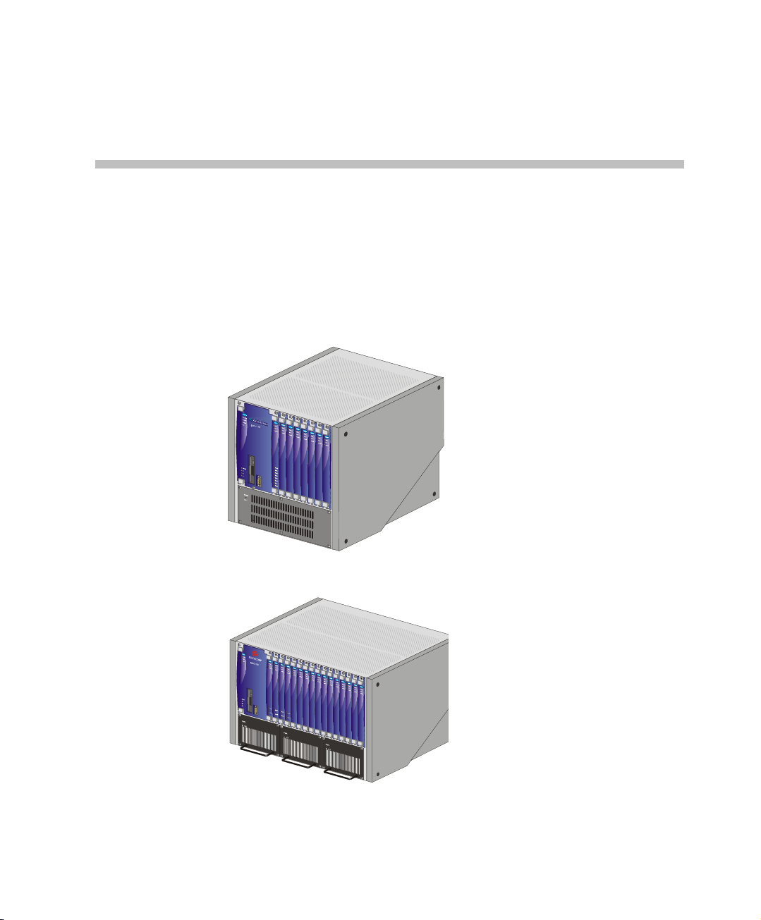
The MGC-50 and the MGC-100 are high performance, high capacity
Multipoint Control Units (MCU) which support up to 48 po rts for the MGC50, and 96 ports for the MGC-100. They utilize a variable port bandwidth
ranging from 56 to 1920 Kbps.
1
Figure 1-1: MGC 50
Figure 1-2: MGC 100
1-1
Page 10

Chapter 1 - Before You Begin
The system meets International Telecommunication Union Telecommunication Standardization Sector, (ITU-T, formerly CCITT)
standards for multipoint multimedia bridging devices, and meets ETSI
standards for telecommunication products. The MGC-100 DC also meets the
NEBS Compliant Standard (when so ordered) for our clients based in the
United States.
The flexible architecture in the system is designed to accommodate users’
changing multipoint needs. This system utilizes a modular “universal slot”
platform that allows the formation of different configurations based on users’
individual port capacity and functionality requirements.
1-2
Page 11

MGC Unit Main Features
The MGC unit offers the following features:
• Supports a large number of ports (48 for the MGC-50, 96 for the MGC-
100) running at 128 Kbps
• Universal slots, telco grade high availability with hot-swappable
modules, redundancy, on-line upgrading and dynamic resource
allocation
• Support for standard network interfaces (ISDN, ATM, T1-CAS, LAN
and V.35 serial) for the easy integration of conference elements into
external network management and billing systems
• Support for up to 16 operator workstations (PCs) connected to either a
local or remote MCU; each operator workstation can be connected to
several MGC units
• Multirate conferencing and Transcoding (audio and video, including
high bit rate video and data bit rate conversion)
• Channel aggregation according to H.221, BONDING and Multirate (H0)
• Automatic rate detection upon endpoint connection to the conference
• H.320/H.323 video, T.120 data and Greet and Guide conferencing
• Enhanced Continuous Presence (multi-image video)
• IVR (Interactive Voice Response)
• Windows 95®/Windows 98®/Windows NT®/Windows 2000®/
Windows XP® based operator statio n
• Multiple operators per conference
• Multiple conferences and MCUs per operator
• TCP/IP - LAN - Internet access
• Supports serial communication (V.35/RS-530/RS-449) (optional)
MGC Hardware and Installation Manual
1-3
Page 12
Chapter 1 - Before You Begin
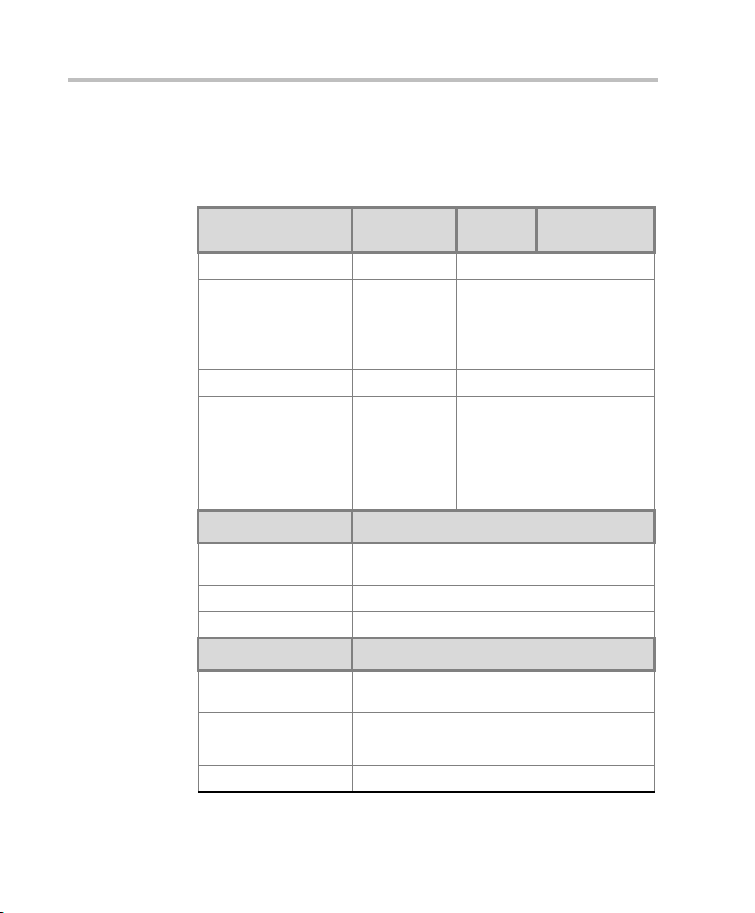
MGC-50/MGC-100 Specifications
Table 1-1 lists the specifications of the MGC-50 and the MGC-100 units.
Table 1-1: MGC Specifications
Physical MGC-50 MGC-100 MGC-100
Height 16” 16” 21”
NEBS
Width 15”, 19” with
mounting plate
Depth 19.5” 19.5” 19.5”
Weight Up to 24 kg Up to 48 kg Up to 58 kg
Free space above the
MCU rack
IP Protocols MGC-50/MGC-100
Audio G.711, G.722 (48), G.722.1, G.728, G.729A, G.
Video H.261, H.263 (Annexes N, F, P), H.264
Data T.120
H. 320 Protocols MGC-50/MGC-100
Audio G.711, G.722 (48 ), G.722.1, G.728, G. 723.1, Siren
3” in standard
installations
723.1, Siren 7, Siren 14
7, Siren 14
23” with
mounting
plates, 19”
with unit at
90°
3” standard
installation,
9” if a MPI8 is to be
fitted
23” with mounting
plates
It is
recommended for
the installer to
refer to the NEBS
Standards
1-4
Video H.261, H.263 (Annexes N, F, P), H.264
Data T.120
Cascading H.243
Page 13
MGC Hardware and Installation Manual
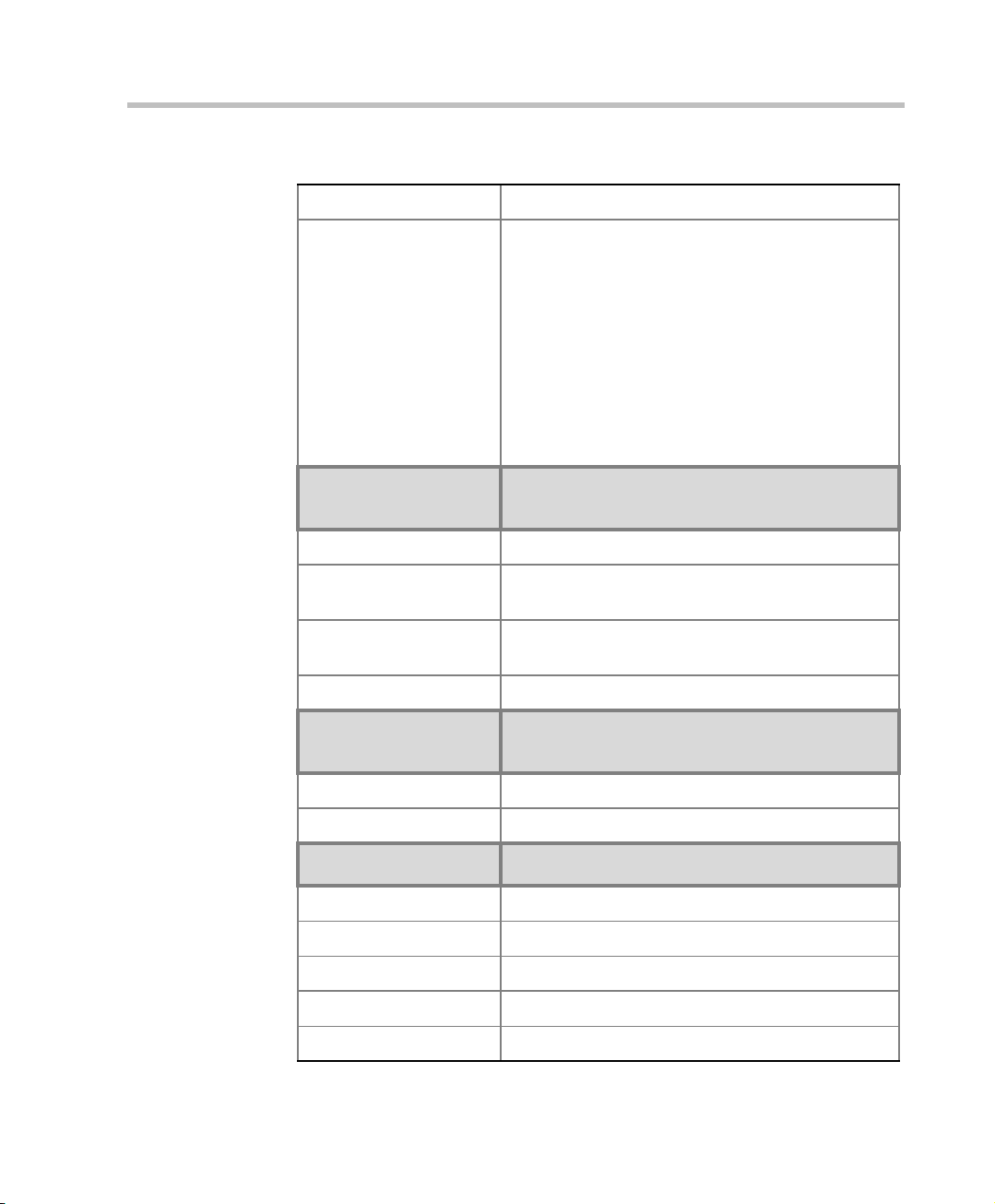
Table 1-1: MGC Specifications
Channel aggregation H.221, BONDING, Multi-Rate (H0)
Network interfaces ISDN:
T1 PRI, E1 PRI, Multirate ISDN, NFAS, Leased
lines-T1/E1, Switched 56
T1-CAS
T1-CAS lines for Audio Only connections
ATM:
25 (FVC.COM), 155 (FVC.COM)
IP (H.323 and SIP):
LAN
Serial:
V.35, RS449, RS530/A
External
Communications
MGC-50/MGC-100
Data rates 56 Kbps - 1920 Kbps (E1)
Network interfaces ISDN T1/ E1, ATM-25 (First Virtual), A TM-155 (First
Virtual), T1-CAS, LAN, serial (MPI)
MGC Manager control
connection
An independent LAN connection (separate from the
Network connection)
Clock synchronization Synchronizes to external network
Local/Remote External
Equipment
MGC-50/MGC-100
Operator workstations LAN/RS-232/Modem/Internet
Reservation systems LAN/Internet/Modem
Environment MGC-50/MGC-100
Operating temperature 10°–40°C (50°–104°F)
Storage temperature -40°–70°C (40°–158°F)
Relative humidity 15%-90% no condensing
Operating altitude Up to approx. 3,000m (10,000ft)
Storage altitude Up to approx. 12,000m (40,000ft)
1-5
Page 14
Chapter 1 - Before You Begin
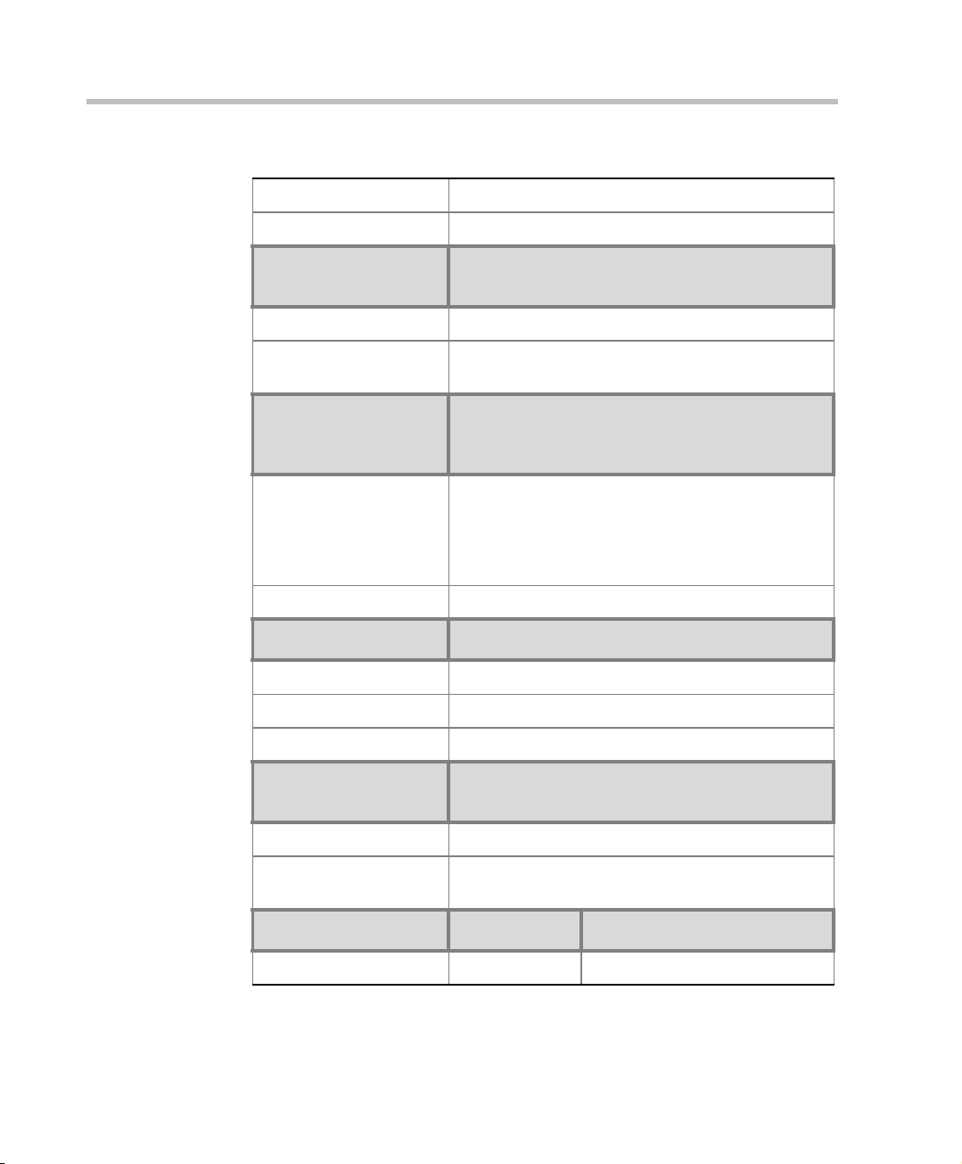
Table 1-1: MGC Specifications
Operating ESD +8kV
Storage ESD +15kV
System
Communications
Integrated scheduler Yes
API to 3rd party
reservation systems
Conference Setup
(Scheduled/
Unscheduled)
Meet Me Per
MGC-50/MGC-100
Yes
MGC-50/MGC-100
• Conference
• MCU
• Channel
• Party
Dial-out/Dial-in Yes
Diagnostics MGC-50/MGC-100
Power up Yes
On-line Yes
Remote Yes
Serviceability /
Reliability
MGC-50/MGC-100
1-6
Hot plug-in modules Yes
Front panel removable
modules
Power Supply MGC-50 MGC-100
DC Input - -48 VDC
Yes
Page 15
Table 1-1: MGC Specifications
MGC Hardware and Installation Manual
AC Input 100-240 VAC,
50/60 Hz
100-240 VAC,
50/60 Hz
Power Consumption MGC-50 MGC-100
AC Maximum Power
consumption
AC Voltage 10Amp at 100
VAC, 5 Amp at
240 VAC
protected by a
12.5 Amp fuse.
Note: Older
MCU units may
have different
power ratings.
Contact your
AC Voltage - 8.5 Amp at 100
VAC and 4.2 Amp at 240 VAC
protected by a 15 Amp circuit
breaker.
DC Voltage - 30 Amp at 48 VDC
protected by a 50 Amp circuit
breaker.
Note: Older MCU units may
have different power ratings.
Contact your next level of
support.
next level of
support.
1-7
Page 16

Chapter 1 - Before You Begin
Scope of Manual
This manual describes the MGC-50 and the MGC-100 hardware and
installation procedure. It is intended for service engineers, system
administrators and system operators who need to install, configure and
maintain the MGC unit.
Detailed information on using the system, including starting and shutting
down the system, is provided in the MGC Manager User’s Guide.
This manual assumes the user has the following knowledge:
• Familiarity with the Windows 95®, Windows 98®, Windows 2000®,
Windows NT®, and Windows XP® environment and interface
• Basic knowledge of videoconferencing concepts and terminology
The MGC Hardware and Installation Manual includes the following topics:
• Chapter 1 - Before You Begin
Provides a general description of the MGC unit, its main features and
description of the MGC Hardware and Installation Guide.
• Chapter 2 - MGC Unit Hardware Installation
Installing the MGC unit and connecting it to the operator workstations.
• Chapter 3 - System Architecture
Describes the system architecture and the data flow.
• Chapter 4 - Hardware Description
Describes the various components that make up the MGC unit.
• Chapter 5 - Maintenance
Describes the controls and LED indicators and provides maint enance
procedures.
• Appendix A - Interfaces Pin Assignment
Describes the pinout of the various MGC unit connectors.
1-8
Page 17

Conventions
Before using this manual, it is important for you to understand the terms and
conventions used:
• The term “Choose” or “Double-click” is used when you need to activate
• The term “Select” or “Click” is used to highlight a part of the window,
• The term “Right-click” is used when you press and release the right
• The term “Choose OK” means that you can either click the OK button
• Keyboard keys appear in capital letters, between these two symbols
• The plus sign (+) between two key names indicates that you must press
• Bold type appearing in the text, or in a procedure indicates the word or
• Italic type appearing in the text or in a procedure indicates the menu
• Tips and notes appear in a different typeface and between two bars. For
MGC Hardware and Installation Manual
a menu command or a command button in the dialog box.
dialog box or menu that you want to be changed with your next action.
mouse button to open a pop-up menu.
with the mouse, or press the <Enter> key on the keyboard.
< >. For example, the Shift key appears as <Shift>.
and hold down one key while pressing down the second key. For
example, “press <Alt>+<P> means that you press and hold down the Alt
key while you press the P key.
the character that you should type into a text box from the ke yboard. It is
also used to indicate the name of the menu name or command name that
you should select.
name, dialog box name or field name from which an option should be
selected or into which parameters should be entered.
example:
This is an example of notes that you may encounter throughout this Hardware
Manual.
1-9
Page 18

Chapter 1 - Before You Begin
List of Abbreviations
The following is the list of abbreviations used throughout this manual:
Table 1-2: Abbreviations
API Application Programming Interface
CSU Channel Service Unit
DPR Dual Port Ram
ESD Electro-Static Discharge
HDLC High-level Data Link Control
HSD High Speed Data
IP Internet Protocol
ISDN Integrated Services Digital Network
1-10
LAN Local Area Network
LED Light Emitting Diode
LSD Low Speed Data
MCU Multipoint Control Unit
MGC Multimedia Gateway Control
MPI Multi Protocol Interface
MUX Multiplexor
PBX Private Branch Exchange
PRI Primary Rate Interface
TCP Transmission Control Protocol
TDM Time Division Multiplexing
Page 19
MGC Hardware and Installation Manual
MGC Hardware and Installation Manual,
Chapter 2
MGC Hardware and Installation Manual,
Chapter 2
MGC Administrator’s Guide,
Chapter 2
MGC Administrator’s Guide,
Chapter 2
MGC Administrator’s Guide,
Chapter 2
MGC Administrator’s Guide,
Chapter 3
MGC User’s Guide - Volume II,
Chapter 6
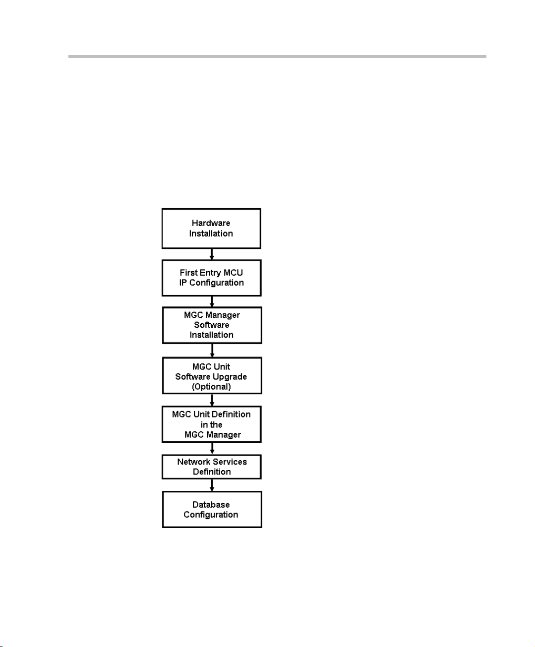
Installation and Configuration Workflow
The MGC unit installation and configuration process includes the following
main steps: Hardware Installation, Software Installatio n, Da tab ase
Configuration, Network Services definition and the MGC unit cards
configuration. The Hardware Install ation stage is de scribed in th is gu ide. The
remaining steps are described in the MGC Administrator’s Guide, as
described in following flowchart.
Figure 1-3: Installation and Configuration Workflow
1-11
Page 20

Chapter 1 - Before You Begin
1-12
Page 21
Hardware Inst allation
MGC Hardware and Installation Manual,
Chapter 2
MGC Hardware and Installation Manual,
Chapter 2
MGC Administrator’s Guide,
Chapter 2
MGC Administrator’s Guide,
Chapter 2
MGC Administrator’s Guide,
Chapter 2
MGC Administrator’s Guide,
Chapter 3
MGC User’s Guide - Volume II,
Chapter 6
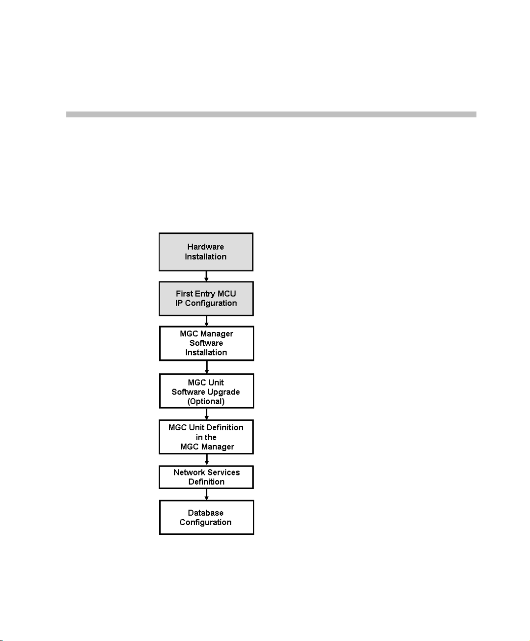
This chapter describes the unpacking and connection of bo th the MGC+50
and the MGC+100, to the ISDN, T1-CAS, H.323, MPI or serial network to
the operator workstation (PC)
2
Figure 2-1: Installation and Configuration Workflow - Hardware Installation
2-1
Page 22
Chapter 2 - Hardware Installation
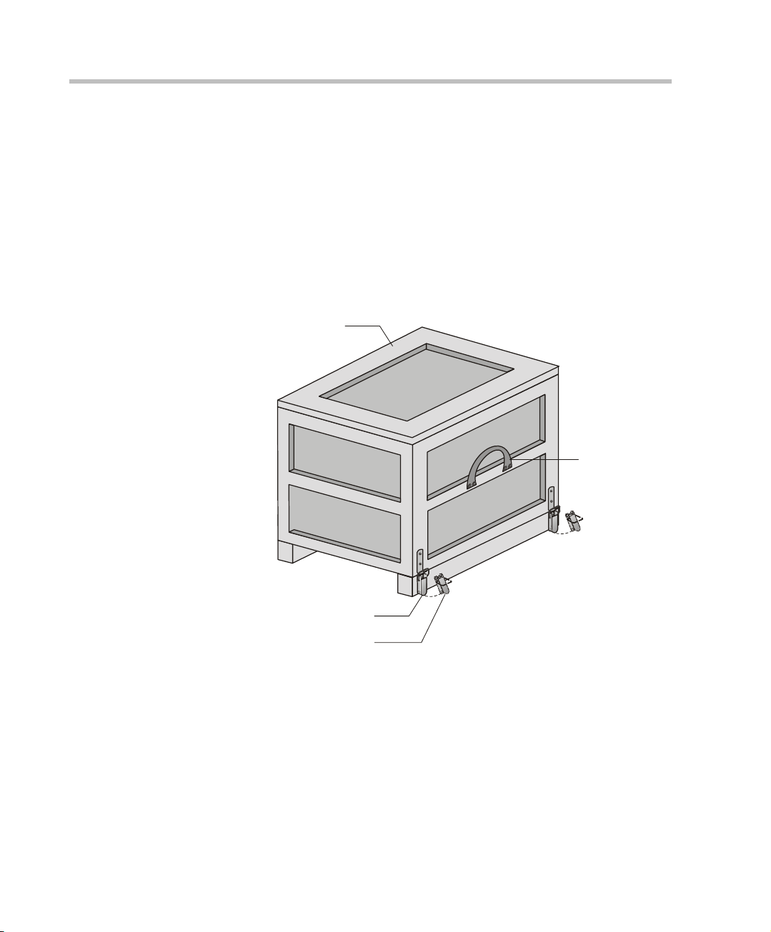
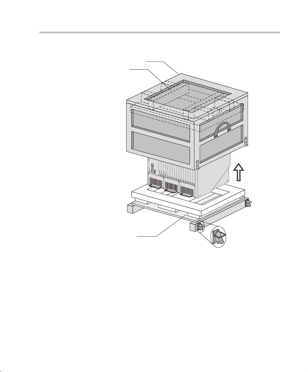
Carrying Strap
Lock in Open Posit ion
Wood Packing Case
Lock in Closed Position
MGC-100 Hardware Installation
Unpacking and Positioning the MGC-100
To unpack and position the MGC-100:
1. When you receive your MGC-100, inspect the equipment for damage
and verify that the components match the packing slip. If you did not
receive a component or if there is damage to the system, notify your
service representative immedi ately.
2-2
Figure 2-1: MGC-100 package
2. Place the MGC-100 unit on a stable flat surface in a location that meets
the MGC environment requirem ents, which are:
• Operating temperature: 10°–40°C (50°–104°F)
• Humidity: 15%–90% non-condensing
• Altitude: Up to 3,000m (10,000ft)
• ESD: +8 kV
Page 23
Foam Block
Foam Block
Wood Packing Case
MGC Hardware and Installation Manual
3. Release the clasp locks at the bottom, and lift the MGC-100 top cover.
Figure 2-2: Unpacking the MGC-100
4. Lift the MGC-100 unit and remove the packaging material.
5. Lower the MGC-100 unit, placing it on the surface.
If the MGC-100 is a standalone unit, place it on a flat surface. If you are
rack mounting the MGC-100, allow a minimum clearance of 3” above
the unit. If you are rack mounting the NEBS MG C-100, the 3” above the
unit is not needed. Refer to the NEBS Standards for clearance
compliance.
2-3
Page 24
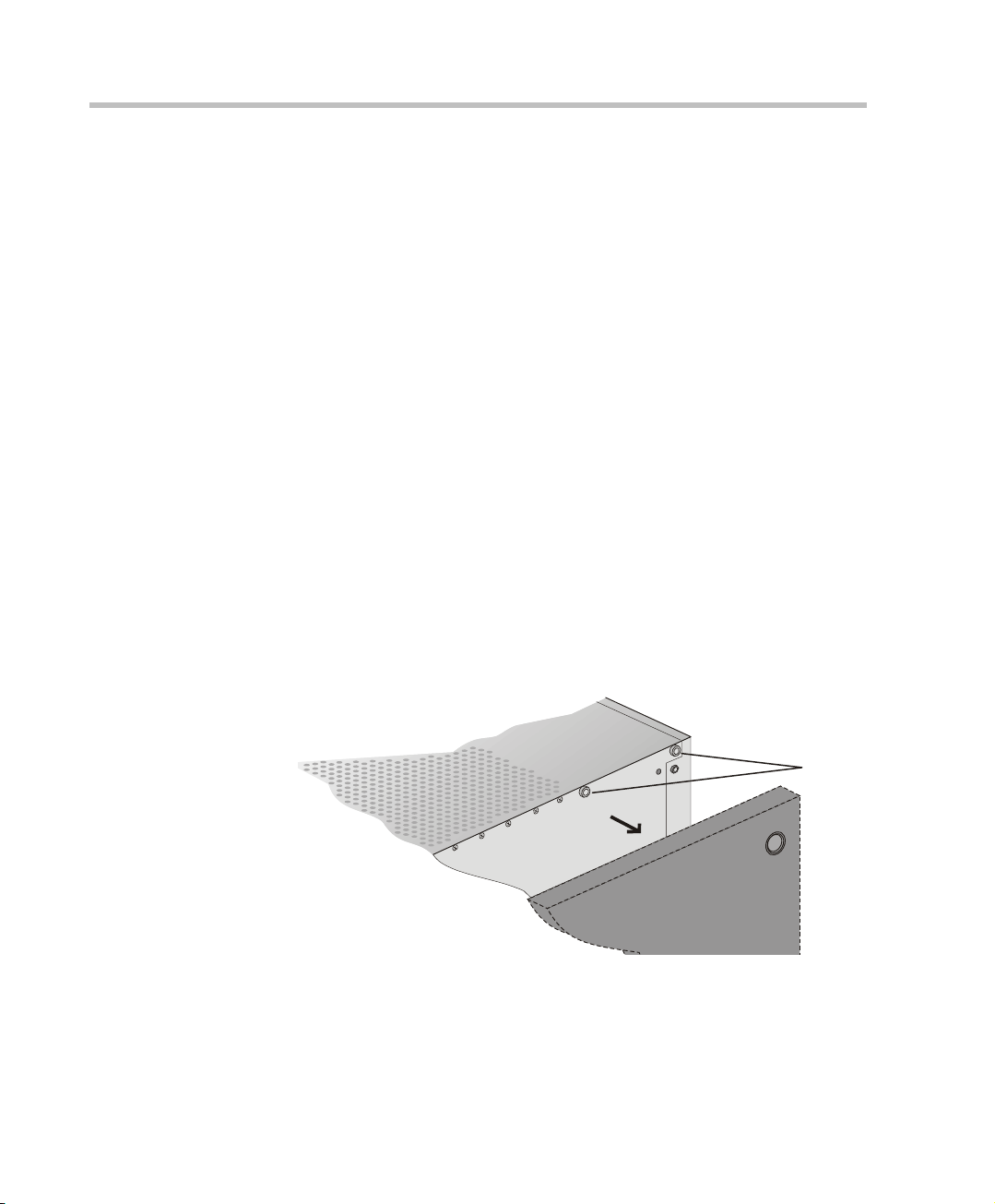
Chapter 2 - Hardware Installation
rear
front
remove
screws
Mounting the MGC-100 on a 23” Rack
The MGC-100 can be mounted to a 23” rack using the two mounting plates
that are pre-installed on the unit.
1. Make sure that the MCU is turned OFF and it is disconnected from the
AC or DC power.
2. Place the MCU in a 23” rack and support it, screw the mounting brac kets
to the rack securing it with bolts and
self-locking nuts (which the client provides).
-orIf the MGC-100 was shipped without the two mounting plates that are
usually pre-installed:
1. Make sure that the MCU power is turn ed OFF and that it is disconnect ed
from the AC or DC power.
2. With a slotted screwdriver remove the five nylon plug hole covers from
the MCU side covers.
3. With an Allen wrench (M4), remove the five screws from the MCU side
covers.
2-4
4. Remove both MCU side covers.
5. Remove the plates from the both sides of the MGC by removing the
appropriate number of functional modules to allow access to the screws.
Page 25
MGC Hardware and Installation Manual
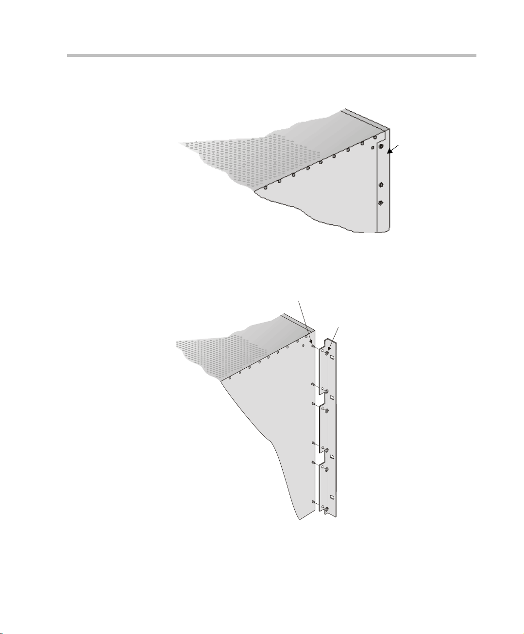
front
Remove
plate
Screw mounting
plate from the
inside of the MGC
Secure with nut
(Front)
6. Unscrew both MCU the side screws and remove both side plates.
7. From the inside of the MGC-100, screw the mounting brackets to both
sides of the MCU, securing the screws in the mounted nuts.
2-5
Page 26
Chapter 2 - Hardware Installation
Power
L1L2L3
Critical
Major
Minor
L0
PWR
IN
OUT
CONT
PWR
IN
OUT
PWR
IN
OUT
Line A
Line B
Stby
Fail
Active
Stby
Fail
Active
Stby
Fail
Active
Stby
Fail
Active
Stby Stby
Fail Fail
Active Active
Stby
Fail
Active
Stby Stby
Fail Fail
Active Active
Stby
Fail
Active
Stby Stby
Fail Fail
Active Active
Stby
Fail
Active
Stby
Fail
Active
Stby
Fail
Active
NET-E1
MUX MUX DATA DATA VIDEO VIDEO VIDEO AUDIOVIDEO AUDIO
Stby
Fail
Active
AUDIOAUDIO
Line 6
Line 7
Line 8
Line 3
Line 4
Line 5
Line 1
Line 2
Line 6
Line 7
Line 8
Line 3
Line 4
Line 5
Line 1
Line 2
Line 6
Line 7
Line 8
Line 3
Line 4
Line 5
Line 1
Line 2
NET-8NET-8 NET-8
19" Attachment Bar
8. Place the MCU in a 23” rack and while supporting it, screw the mounting
brackets to the rack securing it with bolts and self-locking nuts.
When the unit is installed on a rack, the rack must be properly grounded to the
central office ground. The rack must be grounded with two-hole compressiontype connectors using copper conductors (tinned or untinned). Wire, bus bar or
braided strap connectors are acceptable.
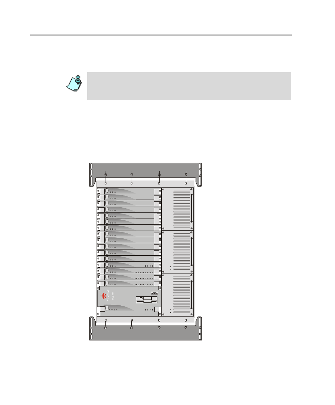
Mounting the MGC-100 on a 19” Rack
The MGC-100 can be mounted in a 19” rack using the mounting kit (P/NKIT2026A). It is highly recommended that the 19” rack be located in an airconditioned room.
Figure 2-3 shows how to mount the MGC-100 on the 19” rack.
2-6
Figure 2-3: MCU Rack Mount
Page 27
MGC Hardware and Installation Manual
Item # 3
Item #4
Because of heat considerations, the MCU must be installed with the Control Unit
Module placed on the left bottom.
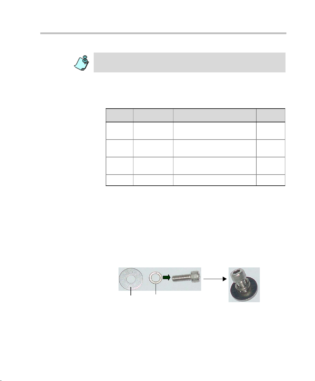
1. Check that all the parts are i n the kit.
The kit should contain the following items:
Table 2-1: 19” Rack Mounting Kit
Item # Polycom P/N Description Quantity
1 MEC2063A 23" TO 19" Mounting Bar MGC-
100 at 90 Degrees
2 SCR2005A Screw 10-32 x 1/2” Allen S/H
ST/ST
3 WAS2003A Washer M5 Spring Latch Loc.
ST\ST
4 WAS2004A Washer M5 Flat ST/ST 8
2
8
8
2. Make sure that the MCU power is turned OFF and it is disconnected
from the AC and DC power.
Remove the side covers as described on page 2-4.
3. If the MCU is a standalone unit, you must first remove the side covers,
and add the mounting brackets to a 23” rack (see pages 2-4 to 2-6).
4. Attach the two mounting bars to the MCU as follows:
a. Fit the spring washer (Item #3) onto the screw (#2).
b. Fit the flat washer (Item #4) onto the screw.
c. Take the two mounting bars (Item #1) from the kit and attach them
to the MGC-100 unit with the screws (wit h the attached washer s, as
described in step b).
2-7
Page 28
Chapter 2 - Hardware Installation
Power
L1
L2
L3
Critical
Major
Minor
L0
CONT
Line A
Line B
Stby
Fail
Active
Stby
Fail
Active
Stby
Fail
Active
Stby
Fail
Active
Stby Stby
Fail Fail
Active Active
Stby
Fail
Active
Stby S tby
Fail Fail
Active Active
Stby
Fail
Active
Stby Stby
Fail Fail
Active Active
Stby
Fail
Active
Stby
Fail
Active
Stby
Fail
Active
NET-E1
MUX MUX DATA DATA
VIDEO VIDEO VIDEO AUDIOVIDEO AUDIO
Stby
Fail
Active
AUDIOAUDIO
Line 6
Line 7
Line 8
Line 3
Line 4
Line 5
Line 1
Line 2
Line 6
Line 7
Line 8
Line 3
Line 4
Line 5
Line 1
Line 2
Line 6
Line 7
Line 8
Line 3
Line 4
Line 5
Line 1
Line 2
NET-8NET-8 NET-8
5. Carefully rotate the MGC-100 counterclockwise 90°, making sure the
Control Unit is at the bottom left.
6. While supporting the MGC-100, place it on the 19” rack and screw the
brackets to the rack, securing it with the screws and nuts supplied with
the rack.
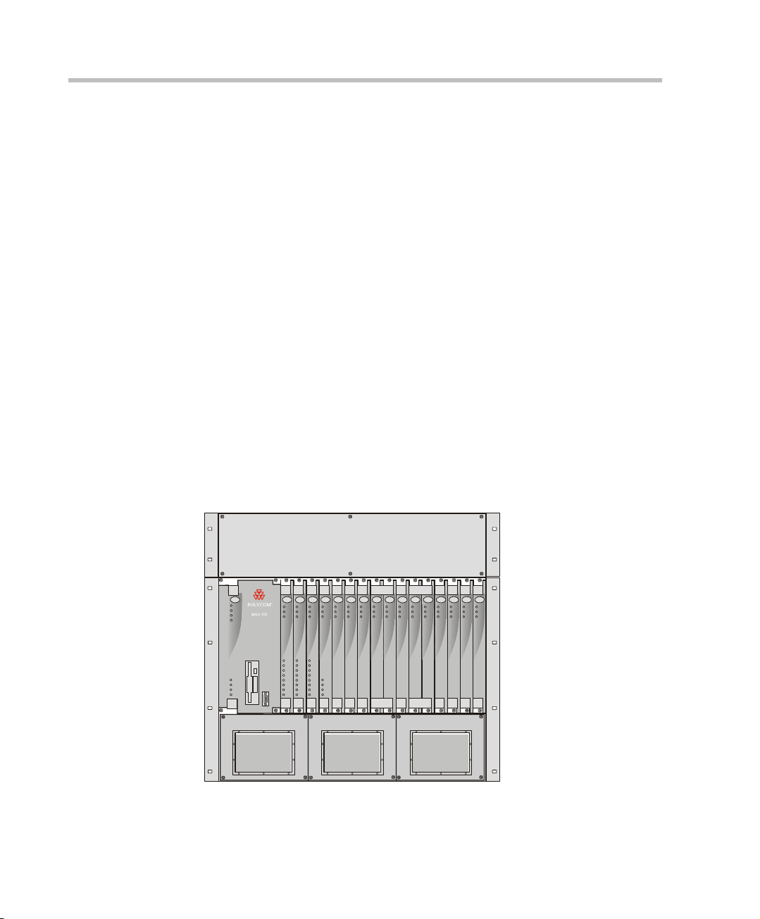
NEBS Standard
For installations based within the United States, an MGC-100 DC NEBS
compliant system is available. The NEBS compliant systems differs in its
construction of the frame and the power supply. All else remains the same.
The construction of the MGC-100 is 12 U’s, (1 U = 4.3 cm) which makes it
higher by 3 U’s than the original frame of the MGC-100. This design allows
for a cushion of air to be present, ensuring safety in case of a heat related
problem.
In addition, the power supply is also designed di fferently by allowing the
circulation of cool air, providing a safety tolerance in case of a heat related
problems.
Use only shielded LAN cables where the shield is grounded at both ends
when connecting to the IO LAN port of the IP+48 on the MGC+ rear panel.
Figure 2-4: NEBS Standard Unit Front View
2-8
Page 29
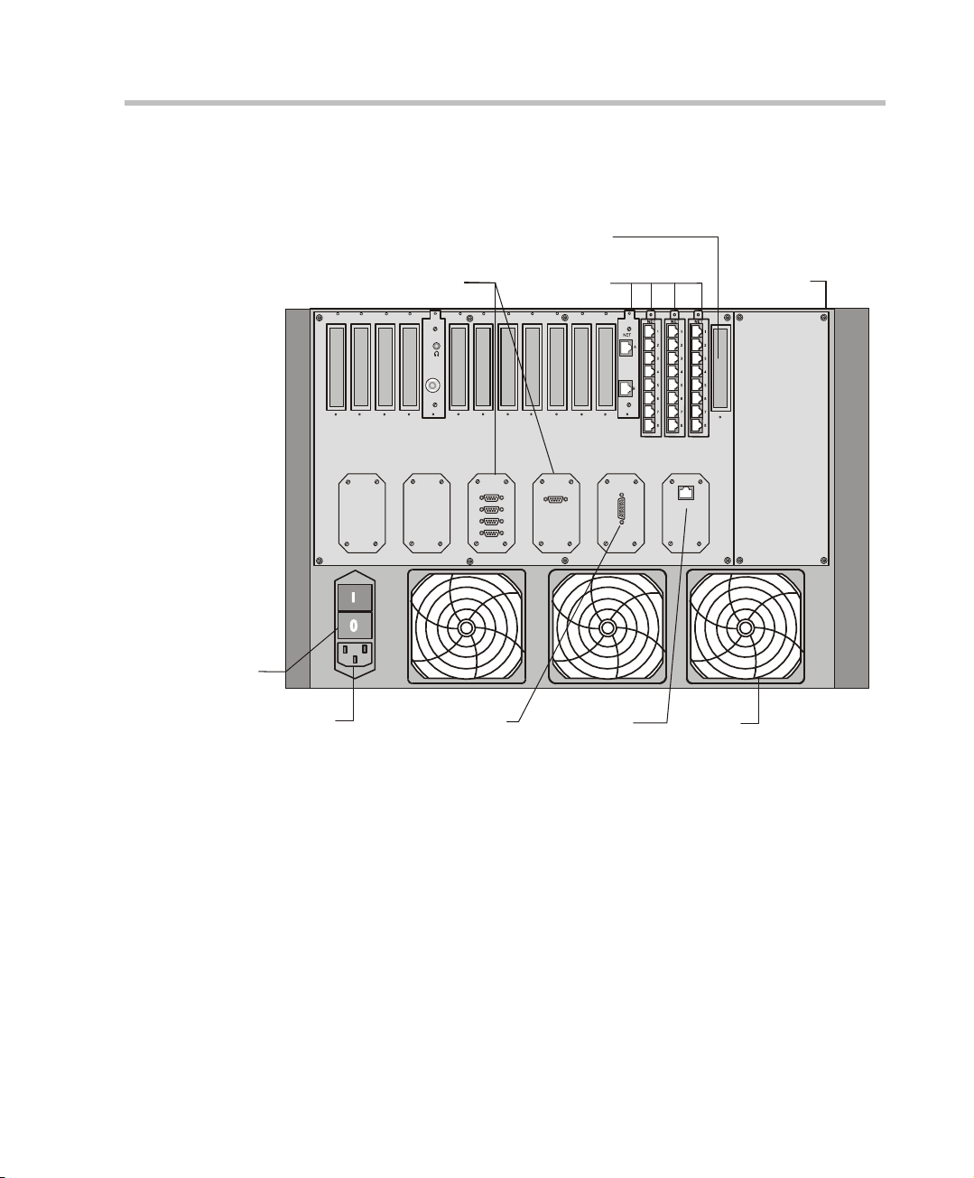
Connecting and Setting Up the MGC-100
LAN
ALARMSCOM 1
COM
MUSIC
LINE IN
AC Inlet
Main Switch
and Circuit Breaker
Main Control
Module Cover
Network
Connectors
RS232
Connectors
Fan
Dry Contacts
RJ45 Connector
Slot A
10/100 Mbits
Use the MGC-100 rear panel diagram below for reference.
MGC Hardware and Installation Manual
Figure 2-5: MGC-100 Rear Panel with External Connectors
To connect the MGC-100 to the network and power source and set up the
system the following procedures are performed:
• Connecting the MGC unit to the power source (AC inlet or -48DC power
distribution unit)
• Connecting the MGC unit to the LAN Network
• Connecting the MGC unit to the Operator Wo rkstation (PC) directly via
RS-232 (optional)
• Connecting the MGC unit to the network(s)
2-9
Page 30
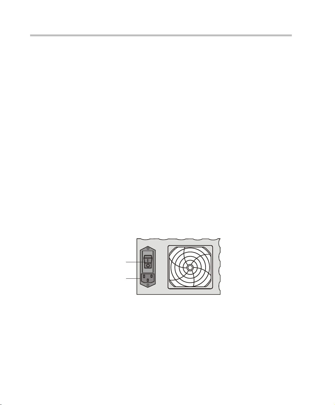
Chapter 2 - Hardware Installation
AC Inlet
Main Switch
MGC-100 Dongle
MGC-100 is shipped with a serial dongle installed on COM 1 on the MCU
rear panel. The dongle is required for normal operation of the MCU. If the
dongle is missing, please contact support.
Connecting to the power source
Y o u can connect to an AC Inl et or to DC power supply acc ording to the power
system used in your site. Follow the steps appropriate to your power system.
The following restrictions apply to the conductors and connectors that may be
used to ground the unit when rack mounted:
• When using bare conductors, they must be coated with an appropriate
antioxidant compound before crimp connections are made. Tinned,
solder-plated or silver-plated connectors do not have to be prepared in
this manner.
• The same bolt assemblies should not secure multiple connectors.
• Listed fastening hardware must be compatible with the materials being
joined and must be preclude loosening, deterioration and electrochemical
corrosion of the hardware and joint materials.
To connect to the AC Inlet:
1. Make sure the power switch is OFF. Insert the power cable into the
power connector on the rear panel of the MGC-100 unit.
2. Insert the power cable into the power source socket.
3. Turn on the power by pressing on the power switch located on the rear
panel of the MGC-100 unit.
2-10
Page 31

MGC Hardware and Installation Manual
COM
Ground
+
-48V
IN
-48V
RTN
ON
OFF
+
-48V
IN
-48V
RTN
ON
OFF
To connect to the -48DC power system:
1. Make sure the power switch is OFF. Turn off the DC power distribution
unit.
2. Using the three wires 10 AWG cable running from the DC power
distribution unit, connect the black wire into the -48IN terminal block
and the red wire to the -48V RTN terminal block.
3. Connect the green or green-yellow wire to the system single-point
“Ground” screw.
If the unit is rack mounted, the single-point grou nd on the MC U must be
connected to the rack with a single conductor and attached as to prevent
loosening.
When using bare conductors, they must be coated with an appropriate
antioxidant compound before crimp connect ions are made. Tinned,
solder-plated or silver plated connectors do not have to be prepared in
this manner.
4. Turn on the DC power distribution unit.
2-11
Page 32

Chapter 2 - Hardware Installation
5. Turn on the power by pressing on the power switch located on the rear
panel of the MGC-100 unit.
Connecting the MGC-100 to the LAN Network
Connect one end of a network cable to t he LAN connector on the rear panel of
the MGC-100 and the other end to the network.
Connecting the MGC-100 to the Operator Workstation (PC) Directly via RS-232 (Optional)
Connect one end of an RS-232 cable to the COM2 connector on the front
panel of the MGC-100 Control Unit and the other end to the serial port of the
operator station (see RS-232 Pin Assignment, A-3).
2-12
Page 33

MGC Hardware and Installation Manual
ISDN network
connection
ISDN Network connection
for 4 spans
ISDN Network connection
for 8 spans
Connecting the MGC-100 to the Network
To connect the MGC-100 to the ISDN network or T1-C AS Network:
The ISDN network is optional. If the MGC-100 has to be connected to the public
ISDN network then an external CSU or similar equipment is needed.
T1-CAS network is optional. It allows you to connect Audio Only participants to
conferences via T1-CAS lines. It uses the same network connections as ISDN
and the procedure described below is applicable to both ISDN and T1-CAS
lines.
• Connect the 8-pin RJ-45 connector of the network cable to the NET
RJ-45 jack on the rear panel of the MGC-100. Repeat this step for each
of the ISDN network lines to be connected to the Network Int erface card
installed in the MCU.
Figure 2-6: ISDN network connection
• Connect one side of the adapter to the NET RJ-45 jack on the rear panel
The ISDN and T1-CAS network properties must be defined in the Network
Services. For details, see the MGC Administrator’s Guide, Chapter 3.
Leased lines should be connected using an adapter with a screw
connector with solid conductor wires or a similar adapter.
of the MGC-100. Then connect the leased line wires to the other side of
the adapter.
2-13
Page 34

Chapter 2 - Hardware Installation
To connect the MGC-100 to the ATM network:
The MGC-100 can be connected to an ATM network. The type of connection
being used differs according to the ATM Network Interface card installed in
the MCU.
If an ATM-25 network interface card is installed, connect the 8-pin
RJ-45 connector of the network cable to t he NET RJ-45 jack on the rear panel
of the MGC-100.
Figure 2-7: ATM-25 network connection
2-14
If an ATM-155 network interface card is installed, first remove the rubber
plug covering the jack. Then connect the fiber optics cable connector to the
jack on the rear panel of the MGC-100.
Figure 2-8: ATM-155 network connect i on
The ATM network properties must be defined in the Network Services, For more
details, see the MGC Administrator’s Guide, Chapter 3.
Page 35

MGC Hardware and Installation Manual
To connect the MGC-100 to the IP network:
If an IP network Interface card is installed in the MGC-100, conn ect the 8-pin
RJ-45 connector of the LAN network cable to the LAN-32 3 RJ-45 jack on the
rear panel of the MGC-100.
Figure 2-9: LAN H.323 network connection
When installing a NEBS compliant system, use only shielded LAN cables where
the shield is grounded at both ends when connecting to the IO LAN port of the
IP+48 on the MGC+ rear panel.
The IP network properties must be defined in the IP Network Service. For
details, see MGC Administrator’s Guide, Chapter 3.
2-15
Page 36

Chapter 2 - Hardware Installation
MPI Box
in 19" Rack
Mounting
Plate
Power
L1
L2
Critical
Major
Minor
L0
CONT
MGC-50
ACCORD
PWR
OUT
Stby
Fail
Active
Line 6
Line 7
Line 8
Line 3
Line 4
Line 5
Line 1
Line 2
StbyStby
FailFail
ActiveActive
StbyStbyStby
FailFailFail
ActiveActiveActive
Stby
Fail
Active
Stby
Fail
Active
VIDEOVIDEO VIDEOVIDEOAUDIOAUDIO
MG-323PRI-8
MPI-4/8 Hardware Installation for the MGC-100
The MPI-4/8 (Multi Protocol Interface) Network Interface card is inserted
into the MGC-100 unit.
The MPI box may be mounted on top of the MGC-100 using mounting
brackets, or on a separate 19” or 23” rack, as can be seen in Figure 2-8. When
installed on a 19” rack, the MPI box can be mounted directly on the rack.
When installed on a 23” rack, a mounting plate must be u sed. If the MGC-100
is rack mounted, there must be at least 6” free space above the MGC-100 to
be able to install the MPI Box on top of the MGC unit.
2-16
Figure 2-10: MPI Box rack mounting options
Page 37

MGC Hardware and Installation Manual
front
rear
remove
screws
To install the MPI-4/8 Network Interface Module:
1. Slide the MPI-4/8 Network Interface module into a free slot in the MGC
front panel.
2. Push the MPI-4/8 Network Interface module firmly into the Backplane,
making sure it is properly seated in its slot.
3. Tighten the screws on the front panel of the MGC-100 that secure the
MPI-4/8 Network Interface module.
To install the MPI Box on Top of the MCU:
1. Turn OFF power to the MCU and unplug it from AC power.
2. If the MCU is rack mounted, disconnect all the external cables, dismount
the MCU from the rack and place it on a desktop or work table.
If it is a standalone unit, remove the MCU side panels.
3. Remove the two Phillips screws on each side of the MCU (near the rear
panel).
2-17
Page 38

Chapter 2 - Hardware Installation
front
rear
tighten
screws
front
rear
4. Place the mounting bracket on top of the MCU aligning it against the
screw openings as shown below and tighten the screws.
5. Mount the bracket on the other side of the MCU (repeat step 4).
6. Place the MPI box with its four 160-pin connectors facing the MCU front
panel between the two mounting brackets. Secure it with the screws
supplied with the MPI Box.
2-18
Page 39

MGC Hardware and Installation Manual
Power
L1
L2
L3
Critical
Major
Minor
L0
PWR
IN OUT
CONT
PWR
IN OUT
PWR
IN
OUT
Line A
Line B
Stby
Fail
Active
NET-8
Stby
Fail
Active
Stby
Fail
Active
Stby
Fail
Active
Stby
Fail
Active
NET-E1
MPINET-8 NET-8
Stby Stby
Fail Fail
Active Active
DATA
Stby
Fail
Active
Stby Stby
Fail Fail
Active Active
DATA
VIDEO VID EO
Stby
Fail
Active
Stby Stby
Fail Fail
Active Active
Stby
Fail
Active
Stby
Fail
Active
VIDEO AUDIOVIDEO AUDIO
Stby
Fail
Active
AUDIOAUDIO
Line 6
Line 7
Line 8
Line 3
Line 4
Line 5
Line 1
Line 2
Line 6
Line 7
Line 8
Line 3
Line 4
Line 5
Line 1
Line 2
Line 6
Line 7
Line 8
Line 3
Line 4
Line 5
Line 1
Line 2
ABA
B
MPI
PORTS
1-4
PORTS
5-8
PORTS
9-12
PORTS
13-16
MGC-100
Power
L1
L2
L3
Critical
Major
Minor
L0
PWR
IN OUT
CONT
PWR
IN OUT
PWR
IN OUT
Line A
Line B
Stby
Fail
Active
NET-8
Stby
Fail
Active
Stby
Fail
Active
Stby
Fail
Active
Stby
Fail
Active
NET-E1
MPI
NET-8
NET-8
Stby Stby
Fail Fail
Active Active
DATA
Stby
Fail
Active
Stby Stb y
Fail Fail
Active Active
DATA
VIDEO VIDEO
Stby
Fail
Active
Stby Stby
Fail Fail
Active Active
Stby
Fail
Active
Stby
Fail
Active
VIDEO AUDIOVIDEO AUDIO
Stby
Fail
Active
AUDIOAUDIO
Line 6
Line 7
Line 8
Line 3
Line 4
Line 5
Line 1
Line 2
Line 6
Line 7
Line 8
Line 3
Line 4
Line 5
Line 1
Line 2
Line 6
Line 7
Line 8
Line 3
Line 4
Line 5
Line 1
Line 2
PORTS
1-4
PORTS
5-8
PORTS
9-12
PORTS
13-16
ABA
B
MPI
MGC-100
7. If the MCU is standalone, reassemble the side panels.
If the MCU is rack mounted, mount the unit on the rack and connect all
the external cables.
8. Using the cable provided with the MPI kit, connect the 160-pin
connector to Port A of the MPI-8 Network Interface front panel. Connect
the other end of the cable to a (Ports 1-4) 160-pin connector of the MP I
Box; by doing this procedure we have utilized the MPI Box as a MPI-4.
9. Using a second cable, connect the angled 160-pin connector to Port B of
the MPI-8 Network Interface front panel. Connect the ot her end of the
cable to B (Ports 5-8) 160-pin connector of the MPI Box.
Using this procedure we have utilized the MPI Box as a MPI-8.
2-19
Page 40

Chapter 2 - Hardware Installation
10. Connect the serial cable running from the DCE to the appr opri ate 37 -pin
connector on the rear panel of the MPI Box. If dialing is used, connect
the appropriate cable from the DCE to the 25 -p in connector on the rear
panel of the MPI Box.
Whenever the MGC unit is used as a DCE and connected straight to an
endpoint the serial data stream flows from the endpoint (DTE) through
the serial connector to the MPI box. The connections stay the same,
meaning; the endpoint is connected to the back of the MPI box by way of
the 37-pin connector , and the other side of the MPI box is th en connected
by way of the 160-pin connector to the MPI card in the MGC unit. For
more information, refer to Chapter 4, “The MPI-8 Network Int erface
Module” on page 4-40.
• If V .35 or RS-530 cable is used, attach the special adapter (provided with the
kit) to the 37-pin prior to connecting the serial cable from the DCE.
• The serial (MPI) network properties must be defined in the Network
Services, For details, see MGC Administrator’s Guide, Chapter 3.
2-20
Page 41

MGC-50 Hardware Installation
Carrying Strap
Lock in Open Posit ion
Wood Packing Case
Lock in Closed Position
Unpacking and Positioning the MGC-50
To unpack and position the MGC-50:
1. When you receive your MGC-50, i nsp ect th e eq ui pmen t fo r damage and
verify that the components match the packing slip. If you did not re ceive
a component or if there is damage to the system, notify Polycom
immediately.
MGC Hardware and Installation Manual
Figure 2-11: MGC-50 package
2. Place the MGC-50 unit on a stable flat surface in a location that meets
the MGC-50’s environment requirements, which are:
— Operating temperature: 10°–40°C (50°–104°F)
— Humidity: 15%–90% noncondensing
— Altitude: Up to 3,000m (10,000ft)
— ESD: +8 kV
2-21
Page 42

Chapter 2 - Hardware Installation
3. Release the clasp locks at the bottom, and lift the MGC-50 top cover.
2-22
Figure 2-12: Unpacking the MGC-50
4. Lift the MGC-50 unit and remove the package base.
5. Lower the MGC-50 unit, placing it on the surface.
If you are rack mounting the MGC-50, allow a minimum clearance of 3
inches above the unit.
Page 43

Mounting the MGC-50 on a Rack
rear
front
remove
screws
The MGC-50 can be mounted in a 19” rack using two mounting plates (Kit
2012A). The side plates are usually mounted when shipped, but if not, follow
the directions below to install the mounted plates on the MGC-50 and then
mount the MGC-50 on the 19” rack.
To install and mount the MGC-50:
1. Make sure that the MGC-50 power is turned OFF and it is disconnected
from the AC power.
2. Remove the five nylon plug hole covers from the MGC-50 protecti ve
side covers (using a slotted screwdriver).
3. Using an Allen wrench (M4), remove the five screws from the MGC-50
side covers.
4. Remove the MGC-50 side covers from both sides.
MGC Hardware and Installation Manual
5. T o remo ve the plate from both MG C-50 sides, the side screws have to be
removed. To remove the screws from the left side the main control
module and the power supply must be removed first. These procedures
are described in Chapter 5 of this manual. For detailed procedures, see
Chapter 5, “Replacing the Main Control M od ul e” on page 5-17. For
instructions on how to remove the power supply see Chapter 5,
“Replacing the Power Supply Module for the MGC-50” o n page 5-12.
2-23
Page 44

Chapter 2 - Hardware Installation
Front
Rear
Remove
plate
Screw mounting
plate from the
inside of the MGC
(Front)
6. Once the Main Control Mo dule, the power supp ly module and the boards
are removed, unscrew the side screws from inside the MGC-50, and then
remove the plate from both MGC-50 sides.
7. From the inside of the MGC-50, screw the mounting bracket to the side
of the MGC-50, securing the screws in the mounted nuts.
2-24
Page 45

MGC Hardware and Installation Manual
MGC-50
in 19" Rack
Plate
Power
L1
L2
Critical
Major
Minor
L0
CONT
MGC-50
ACCORD
PWR
OUT
Stby
Fail
Active
Line 6
Line 7
Line 8
Line 3
Line 4
Line 5
Line 1
Line 2
StbyStby
FailFail
ActiveActive
StbyStbyStby
FailFailFail
ActiveActiveActive
Stby
Fail
Active
Stby
Fail
Active
VIDEOVIDEO VIDEOVIDEOAUDIOAUDIO
MG-323PRI-8
8. To remove the plate from the right side of the MGC unit remove the
appropriate number of functional modules to allow access to the screws.
9. From the inside of the MGC-50, screw the mounting bracket to the side
of the MGC-50, securing the screws with the mounted nuts.
10. Insert the functional modules removed earlier into the MGC-50.
11. Mount the Power Supply module and Main Con trol Module bac k in their
place as described in Chapter 5, “Replacing the Main Control Module,”
page 5-18 and “Replacing the Power Supply Module,” page 5-12.
12. Place the MGC-50 in a 19” rack and while supporting it, screw the
mounting brackets to the rack securing it with nuts.
2-25
Page 46

Chapter 2 - Hardware Installation
AC Inlet
Main Switch
Fuse
IO Card
Fan
RJ45
Connector
LAN
COM 1
Main Control
Module Cover
Connecting and Setting Up the MGC-50
Use the MGC-50 rear panel diagram below for reference.
2-26
Figure 2-13: MGC-50 Rear Panel with External Connectors
To connect the MGC-50 to the network and power source and set up the
system the following procedures are performed:
• Connecting the MGC unit to the power source (AC inlet)
• Connecting the MGC unit to the LAN Network
• Connecting the MGC unit to the Operator Workstation (PC) directly via
RS-232 (optional)
• Connecting the MGC unit to the network(s)
MGC-50 Dongle
MGC-50 is shipped with a serial dongle installed on COM1 on the MCU rear
panel. The dongle is required for normal operation of the MCU. If the dongle
is missing, please contact support.
Page 47

MGC Hardware and Installation Manual
AC Inlet
Main Switch
Connecting to the Power Source
To connect to the AC Inlet:
1. Make sure that the power switch located on the rear panel of the MGC
unit is off.
2. Insert the power cable into the power connector on the rear panel of the
MGC-50 unit.
3. Insert the power cable into the power source socket.
4. Turn on the power by pressing on the power switch located on the rear
panel of the MGC-50 unit.
If the unit is rack mounted, the single-point ground on the MCU-5 0 must
be connected to the rack with a single conductor and attached so that it
prevents loosening.
The following restrictions apply to the conductors and connectors that
may be used to ground the unit when rack mounted:
— When using bare conductors, they must be coated with an
appropriate antioxidant compound before crimp connections are
made. Tinned, solder-plated or silver plated connectors do not have
to be prepared in this manner.
— Multiple connectors should not be secured with the same bolt
assemblies.
— Listed fastening hardware must be compatible with the materials
being joined and must avoid loosening, deterioration and
electrochemical corrosion of the hardware and joint materials.
2-27
Page 48

Chapter 2 - Hardware Installation
Connecting the MGC-50 to the LAN Network
Connect one end of a network cable to t he LAN connector on the rear panel of
the MGC and the other end to the network.
Connecting the MGC-50 to the Operator W orkst ation (PC) Directly via RS-232 (Optional)
Connect one end of an RS-232 cable to the COM 2 connector on the front
panel of the MGC Control Unit and the other end to the serial port of the
operator station (See RS-232 Pin Assignment, A-3).
Connecting the MGC-50 to the Network
To connect the MGC-50 to the ISDN network and T1-CAS network:
2-28
This is an optional Network Interface Card. If the MGC-50 has to be connected
to the public ISDN network then an external CSU or where required, similar
equipment is needed.
T1-CAS network is optional. It allows you to connect Audio Only participants to
conferences via T1-CAS lines. It uses the same network connections as ISDN
and the procedure described below is applicable to both ISDN and T1-CAS
lines.
• Connect the 8-pin RJ-45 connector of the network cable to the NET
RJ-45 jack on the rear panel of the MGC. Repeat this step for each of the
ISDN network lines to be connected to the Network Interface card
installed in the MCU.
Page 49

MGC Hardware and Installation Manual
ISDN network
connection
ISDN Network connection
for 4 spans
ISDN Network connection
for 8 spans
Figure 2-14: ISDN network connection
• Leased lines should be connected using an adapter with a screw
connector for solid conductor wires with a diameter in the range 0.4 to
0.6 mm. Use Polycom P/N CBL0602A or similar adapter.
Connect one side of the adapter to the NET RJ-45 jack on the rear panel
of the MGC. Then connect the leased line wires to the other side of the
adapter.
The ISDN and T1-CAS network properties must be defined in the Network
Services. For details, see the MGC Administrator’s Guide, Chapter 3.
2-29
Page 50

Chapter 2 - Hardware Installation
Connecting the MGC-50 to the ATM Network
The MGC-50 can be connected to an ATM network. The type of connection
used differs according to the ATM Network Interface card installed in the
MCU.
If an ATM-25 network interface card is installed, connect the 8-pin
RJ-45 connector of the network cable to t he NET RJ-45 jack on the rear panel
of the MGC.
Figure 2-15: ATM-25 network connection
If an ATM-155 network interface card is installed, first remove the rubber
plug covering the jack. Then connect the fiber optics cable connector to the
jack on the rear panel of the MGC.
2-30
Figure 2-16: ATM -155 network connection
The ATM network properties must be defined in the Network Services, for
details, see the MGC Administrator’s Guide, Chapter 3.
Page 51

MGC Hardware and Installation Manual
Connecting the MGC-50 to the IP Network
If an IP network Interface card is installed in the MGC, connect the 8-pin
RJ-45 connector of the LAN network cable to the LAN-32 3 RJ-45 jack on the
rear panel of the MGC.
Figure 2-17: LAN IP network connection
The IP network properties must be defined in the IP Network Service. For
details, see MGC Administrator’s Guide, Chapter 3.
2-31
Page 52

Chapter 2 - Hardware Installation
MPI Box
in 19" Rack
Mounting
Plate
MPI Box
Power
L1
L2
Critical
Major
Minor
L0
CONT
MGC-50
ACCORD
PWR
OUT
Stby
Fail
Active
Line 6
Line 7
Line 8
Line 3
Line 4
Line 5
Line 1
Line 2
StbyStby
FailFail
ActiveActive
StbyStbyStby
FailFailFail
ActiveActiveActive
Stby
Fail
Active
Stby
Fail
Active
VIDEOVIDEO VIDEOVIDEOAUDIOAUDIO
MG-323PRI-8
MPI-8 Hardware Installation for the MGC-50
The MPI-8 Network Interface card is inserted into the MGC-50.
The MPI box is mounted on a 19” rack together with the MGC-50, as can be
seen in Figure 2-15. The MPI box is mounted directly on the rack, above the
MGC-50, leaving at least 6” free space above the MGC-50. For details, on
how to mount the MGC-50, refer to the section “Mounting the MGC-50 on a
Rack” on page 2-23.
2-32
Figure 2-18: MPI Box mounting option
Page 53

MGC Hardware and Installation Manual
PORTS
1-4
PORTS
5-8
PORTS
9-12
PORTS
13-16
To install the MPI-8 Network Interface Module:
1. Slide the MPI-8 Network Interface module into a free slot in the MCU
front panel.
2. Push the MPI-8 Network Interface module firmly into the Backplane,
making sure it is properly seated in its slot.
3. Tighten the screws on the front panel of the MGC-50 that secure the
MPI-8 Network Interface module.
To mount the MPI Box on the Rack for the MGC-50:
1. Turn OFF power to the MCU and unplug it from AC power.
2. If the MCU is rack mounted, disconnect all e xternal cable s, dismount the
MCU from the rack and place it on a desktop or work table
3. Place the MPI box with is four 160-pin connectors facing the MGC-50
front panel between the two rails of the rack. Secure it to the rack with
the screws supplied with the MPI Box.
4. Connect all the external cables to the MPI box:
Using the cable provided with the MPI kit, connect the 160-pin
connector to Port A of the MPI-8 Network Interface front panel. Connect
the other end of the cable to a (Ports 1-4) 160-pin connector of the MP I
Box. Again, by doing this procedure we have utilized the MPI Box as a
MPI-4.
2-33
Page 54

Chapter 2 - Hardware Installation
Power
L1
L2
L3
Critical
Major
Minor
L0
CONT
MGC-50
ACCORD
PWR
OUT
Stby
Fail
Active
Line 6
Line 7
Line 8
Line 3
Line 4
Line 5
Line 1
Line 2
StbyStby
FailFail
ActiveActive
StbyStbyStby
FailFailFail
ActiveActiveActive
Stby
Fail
Active
Stby
Fail
Active
VIDEOVIDEO VIDEOVIDEOAUDIOAUDIO
MPIPRI-8
PORTS
1-4
PORTS
5-8
PORTS
9-12
PORTS
13-16
Using a second cable, connect the 160-pin connector to Port B of the
MPI-8 Network Interface front panel. Connect the other end of the cable
to B (Ports 5-8) 160-pin connector of the MPI Box. By doing this
procedure we have utilized the MPI Box as a MPI-8.
2-34
5. Connect the serial cable running from th e DCE to the appr opri ate 37 -pin
connector on the rear panel of the MPI Box (If the endpoint is a DCE,
then connect this to the MPI Box. For more information, refer to chapter
4). If dialing is used, connect the appropriate cable from the DCE to the
25-pin connector on the rear panel of the MPI Box.
• If the V .35 or RS-530 cable is used, attach the special adapter (provided with
the kit) to the 37-pin prior to connecting the serial cable from the DCE.
• The serial (MPI) network properties must be defined in the Network
Services, for details, see MGC Administrator’s Guide, Chapter 3.
Page 55

MGC Hardware and Installation Manual
First Entry IP Configuration
This following section describes the first entry IP Configuration for
pSOSystem and XPEK Operating Systems.
IP Configuration Change on XPEK and pSOS OS
1. Connect a Hub or cross-over LAN cable between the laptop’s LAN
connection and the LAN connection of the Control Unit.
2. On the laptop, click Control Panel ->Network Connection->Local
Area Connection.
3. In the Local Area Connection - General dialog box
button.
4. In the Local Area Connection Properties dialog box and click Use the
following IP address.
5. Type the IP address 129.254.4.7 (of the laptop as part of the network
segment on the MCU).
6. Click OK.
7. Run the MGC Manager application.
8. Define a new MCU:
a. In the Browser pane, right-click the MCUs Network icon, and then
click New MCU.
, click the Properties
2-35
Page 56

Chapter 2 - Hardware Installation
b. In the Name box, enter the name of the MCU.
c. In the IP Address box, enter the factory-setting IP
d. Click OK.
9. In the MCUs list, double-click the MCU icon to connect to it.
The Add MCU dialog box opens.
Specify a name that clearly identifies the MCU.
Address:129.254.4.8.
The new MCU is added to the MCUs list.
2-36
Page 57

MGC Hardware and Installation Manual
10. Modify the IP address of the MCU unit as allocated by the netwo rk
administrator . This is the IP address with which the MCU is identified on
the LAN site:
a. Right-click the MCU icon, and then click IP Configuration.
The IP Configuration dialog box opens.
b. The following parameters should be modified to match the actual
network:
2-37
Page 58

Chapter 2 - Hardware Installation
11. Click OK.
12. Exit the MGC Manager and switch OFF the MCU.
13. Disconnect the MCU from the cross-over cable.
14. Connect the MCU to your site’s network.
15. Switch ON the MCU.
a. Right-click the MCU icon, and then click Properties.
Table 2-2: IP Configuration Options
Option Description
IP Address The system displays the currently defined IP
address. Enter the IP address allocated to the
MCU by the network administrator.
Subnet Mask Enter the Subnet Mask of the MCU.
Default Gateway Enter the IP Address of the default gateway/
router.
2-38
Page 59

MGC Hardware and Installation Manual
The current MCU name.
To modify, type a new
name
MCU IP address. Enter
the IP address of the MCU
as allocated by the
network administrator
The MCU Properties dialog box opens.
b. Enter the IP address of the MCU as you have defined in the IP
Configuration.
c. Click OK.
Using a DOS Diskette with the Updated LAN.CFG File
1. Using Windows Notepad, create a new text file with the following text:
IP_ADDRESS = aaa.bbb.ccc.ddd
NETWORK_MASK = aaa.bbb.ccc.ddd
DEFAULT_GATEWAY = aaa.bbb.ccc.ddd,
where aaa, bbb, ccc, and ddd are numbers between 0 to 255, as follows:
Table 2-3: IP Configuration Options
Option Description
IP Address Enter the IP address allocated to the MCU by
Subnet Mask Enter the IP address of the subnet mask.
Default Gateway Enter the IP address of the default gateway.
the network administrator.
2-39
Page 60

Chapter 2 - Hardware Installation
2. Save the information, creating a tex t file named LAN.CFG.
3. Copy the file to an empty DOS diskette.
4. Turn on the MCU and wait for the Power LED to blink.
5. Insert the DOS diskette to the MCU diskette drive.
6. The MCU reads information from the diskette se veral times. Wait for the
floppy to stop blinking.
7. Remove the diskette from the diskette drive.
8. Connect the MCU to your site’s network.
9. Define a new MCU using the IP address you have entered in the
LAN.CFG file:
a. In the Browser pane, right-click the MCUs Network icon, and then
click New MCU.
The Add MCU dialog box opens.
2-40
b. In the Name box, enter the name of the MCU. Specify a name that
clearly identifies the MCU.
c. In the IP Address box enter the default IP Address of the MCU as
entered in the LAN.CFG file.
d. Click OK.
The new MCU is added to the MCUs list.
Page 61

Clocking
MGC Hardware and Installation Manual
To be able to work with the network connected to the MCU you need to
synchronize the system clock with the network clock. This is done in two
steps:
• Selecting the network type according to which the system clock will
synchronize. Only one system type may be selected for clocking . The
clock source is then defined in the “system cfg”.
• Selecting the spans of the selected network that will act as Master and
Backup clocks. The Master and the Backup clock must be set on spans of
the same network type.
For more details regarding the clocking setup, see the MGC Administrator’s
Guide, “Clocking” in Chapter 5.
You have completed the hardware installation. The next step in the
installation procedure is to install the MGC Manager software. For more
information, refer to the MGC Administrator’s Guide, Chapter 2.
2-41
Page 62

Chapter 2 - Hardware Installation
2-42
Page 63

System Architecture
MGC-50
MGC-100
Operator Workstation
LAN / WAN / RS-232
The MGC unit is designed to provide maximum reliability, minimum
interruptions, and effortless maintenance. Removable active components are
accessed via the front panel to provide quick and easy serviceability.
Redundant power supplies are easily accessed via the front panel, ensuring a
fail safe operation (the MGC-50 is not redundant, therefore not hotswappable). Network connections on the back of the unit enable easy
module removal and prevent accidental disconnection.
All Functional Modules are front-removable and hot-swappable, allowing
servicing functions to be performed while the system is in operation.
The operator accesses the MGC unit from an operator work station which is
connected to the MGC unit via an Ethernet interface or an RS-232 interface,
as shown in Figure 3-1, “MGC interfaces”.
3
Figure 3-1: MGC interfaces
Figure 3-2, “MGC-100 Components” on page 3-2 and Figure 3-3, “MGC-50
components” on page 3-3 sho w the internal layout of the MGC-100 and the
MGC-50, respectively. All of the MGC modules and cards connect to the
backplane.
3-1
Page 64

Chapter 3 - System Architecture
ISDN Network I/F
ATM Network I/F
H.323 Network I/F
MUX
Audio
Video
Data
H.323 I/O
NET I/O
ATM I/O
MUSIC I/O
Rear
Backplane
Front
Main Control
Module
Power Supply
Module
The MGC Unit is made up of:
• Main Control Module, located at the top left of the unit when viewed
from the front
• Functional Modules, located to the right of the Main Control Module
when the unit is viewed from the front
• Power Supply Module, located underneath the Main Control Module and
Functional Modules
• Input/Output cards, located behind the backplane opposite the Functional
Modules.
The various modules communicate with each other via the Backplane. The
Control Bus and Information Highway are implemented on the Backplane.
Figure 3-2 describes the functional block diagram of the MGC-100
components.
3-2
Figure 3-2: MGC-100 Components
Page 65

MGC Hardware and Installation Manual
MUSIC I/O
H.323 I/O
NET I/O
Rear
Backplane
Front
Power Supply
Module
Main Control
Module
PRI-8
Audio
Audio
Video
Video
MG-323
Video
Video
Figure 3-3 describes the functional block diagram of the complete MGC-50.
Figure 3-3: MGC-50 components
3-3
Page 66

Chapter 3 - System Architecture
Hard
Disk
RS232
RS232
Main
CPU
Ethernet
LAN
Interface
Serial
Inteface
Comm.
Controller
C
8
M
CPU Bus
Control Bus
Information Highway
Main
Control
Module
Operator
Workstation
Functional
Modules
H323
Network
ATM
Network
ISDN
Network
Audio
Module
Video
Module
Data
Module
MUX
Module
MPI
Network
Interface
ATM
Network
Interface
H323
Network
Interface
ISDN
Network
Interface
MPI
Box
DCE
Figure 3-4 shows the physical layout of the MGC-100 and how it interfaces
with the outside world.
3-4
Figure 3-4: MGC unit functional block diagram
Page 67

MGC Hardware and Installation Manual
RS232
RS232
Ethernet
Power
Module
Power
Module
Power
Module
Fan
Module
Audio
Module
Video
Module
Data
Module
Power Bus
Communication Bus
Information
Power Plane
Serial
Interface
Main
CPU
Comm.
Controller
LAN
Interface
CPU Bus
Floppy Disk
Hard Disk
LAN
Alarms
Workstations
Workstations
120/230 V
ISDN
Network
CSU/PABX
ATM
Network
H323
Network
Serial
equipment
I/O
Card
I/O
Card
I/O
Card
Main
Control
Module
Power
Supply
Unit
MGC-100
MUX
Module
MPI
Network
Interface
ATM
Network
Interface
H323
Network
Interface
ISDN
Network
Interface
MPI
Box
Functional
Modules
Figure 3-5 shows the physical layout of the MGC-100 and how it interfaces
with the outside world.
Figure 3-5: MGC-100 functional block diagram
3-5
Page 68

Chapter 3 - System Architecture
RS232
RS232
Ethernet
Power
Module
Power
Module
Power
Module
Fan
Module
Audio
Module
Video
Module
Data
Module
Power Bus
Communication Bus
Information
Power Plane
Serial
Interface
Main
CPU
Comm.
Controller
LAN
Interface
CPU Bus
Floppy Disk
Hard Disk
LAN
Alarms
Workstations
Workstations
120/230 V
ISDN
Network
CSU/PABX
ATM
Network
H323
Network
Serial
equipment
I/O
Card
I/O
Card
I/O
Card
Main
C
o
n
t
r
o
lMo
d
ule
Functional
Modules
Power
Supply
Unit
MGC-100
MUX
Module
MPI
Network
Interface
ATM
Network
Interface
H323
Network
Interface
ISDN
Network
Interface
MPI
Box
Figure 3-6 shows the physical layout of the MGC-50 and how it interfaces
with the outside world.
Figure 3-6: MGC-50 functional block diagram
3-6
Page 69

Information Flow
I/O Card
I/O Card
H.323 Network
Interface
Module
(includes MUX)
ISDN/ATM/MPI
Network
Interface
Module
MUX
Module
Video
Module
Data
Module
Main
Control
Module
Audio
Module
H323
ATM
MPI
Figure 3-7 shows the flow of information within the system.
The MUX Module is not used with the H.323.
MGC Hardware and Installation Manual
Figure 3-7: Signal flow process
Information enters the MGC units from the telecommunic ations network via a
PBX or CSU, and into the Network Interface Module. The information is then
transferred to the MUX Module via the Internet.
The MUX Module transfers the control information to the Main Control
Module via the Control Bus. The control information is then processed by the
Main Control Module and a control response forwarded via the Control Bus
to the appropriate MUX Ports.
3-7
Page 70

Chapter 3 - System Architecture
The MUX module divides the incoming information into audio, video and
data components, and then forwards the information to the appropriate
functional module. The information arriving at the MUX po rts is multiplex ed
into Nx56/64 Kbps channels. These channels can be hyperchannels or
aggregated channels, depending on the capabilities of the network and the
receiving terminals.
The MUX Module transfers audio information to the Audio Module via the
Information Highway. The audio information is then processed by the Audio
Module and forwarded via the Information Highway to the appropriate MUX
ports.
The MUX Module transfers video information to the Video Module via the
Information Highway. There are two modes of video operation during a
conference:
• Video Switching, where the speaker is the only person shown on the
screen. The MUX module broadcasts the video of the current speaker to
all sites involved in the conference.
• Continuous Presence, where several participants are shown on the
screen. The video information is processed by the Video Module and
forwarded via the Information Highway to the appropriate MUX Ports.
The MUX Module transfers T.120 data (which follows the ITU-T T.120
standard for data transfer and application sharing in a multipoint conference)
to the Data Module via the Information Highway. The data information is
processed by the Data Module and forwarded to the appropriate MUX Ports.
After the audio, video, and data information has been processed, the
processed information flows back to the MUX module for multiplexin g, after
which it is sent to the network via the Network Interface module and the
Input/Output card. This information is then transferred to the Network
Interface module via the Information Highway. The information is then ready
for transmission.
3-8
Page 71

MGC Manager Interface
As shown in Figure 3-4, “MGC unit functional block diagram” on page 3-4,
the Main Control Unit communicates with the MGC Manager through the
LAN interface or the RS-232 interface.
Power Supply Flow
For the MGC-100, the AC power inlet is connected by a switch through a 15
Amp. circuit breaker and then filtered to the AC power supply module. The
DC power outlet delivers 5V, 12V, and -12V through the power bus in the
Backplane to the functional units and the Main Control Module. The 12V is
also delivered to the fans.
For the MGC-50, the AC power inlet is connected through a 12.5 amp. 250
volt fuse and then filtered to the AC power supply module.
MGC Hardware and Installation Manual
3-9
Page 72

Chapter 3 - System Architecture
3-10
Page 73

Hardware Description
This chapter describes the various components that make up the MGC unit.
The following components are described:
• Backplane
• Main Control Module
• Power Supply Module
• Fans
• Functional Modules
— ISDN Net-T1/Net-E1
— ISDN/T1-CAS Net-2/4/8
— ATM-25/155
— MG323
—IP24
—IP48
— IP+12, IP+24, IP+48
—MPI-4/8
—MUX
—MUX+
— Standard Audio
—Audio+8A/V
— Audio+12/24, Audio+24/48, Audio+48/96
— Standard Video
—Video+
—Data
•
Input/Output cards
• Greet&Guide hardware kit
4
4-1
Page 74

Chapter 4 - Hardware Description
Power Supply Module Handle
Ejectors
LEDs
Floppy Disk Drive
Main
Control
Module
COM Port
Power
L1
L2
L3
Critical
Major
Minor
L0
PWR
IN
OUT
CONT
PWR
IN
OUT
PWR
IN
OUT
Line A
Line B
Stby
Fail
Active
Stby
Fail
Active
Stby
Fail
Active
Stby
Fail
Active
Stby Stby
Fail Fail
Active Active
Stby
Fail
Active
Stby Stby
Fail Fail
Active Active
Stby
Fail
Active
Stby Stby
Fail Fail
Active Active
Stby
Fail
Active
Stby
Fail
Active
Stby
Fail
Active
NET-E1
MUX MUX DATA DATA
VIDEO VIDEO VIDEO AUDIOVIDEO AUDIO
Stby
Fail
Active
AUDIO
AUDIO
Functional Modules
Line 6
Line 7
Line 8
Line 3
Line 4
Line 5
Line 1
Line 2
Line 6
Line 7
Line 8
Line 3
Line 4
Line 5
Line 1
Line 2
Line 6
Line 7
Line 8
Line 3
Line 4
Line 5
Line 1
Line 2
NET-8NET-8 NET-8
MGC-100
MGC-100 Components Location
Figure 4-1 shows the front panel of the MGC-100. The front panel provides
access to the Main Control Module, the Functional Modules, and the Power
Supply Modules. Status LEDs on the Main Control Module, Functional
Modules, and Power Supply Modules indicate the status of the system.
4-2
Figure 4-1: MGC-100 front panel
Page 75

MGC Hardware and Installation Manual
LAN
ALARMSCOM 1
COM
MUSIC
LINE IN
AC Inlet
Main Switch
and Circuit Breaker
Main Control
Module Cover
Network
Connectors
RS232
Connectors
Fan
Dry Contacts
RJ45 Connector
Slot A
10/100 Mbits
Figure 4-2 shows the rear panel of the MGC-100. The rear panel provides
access to the network I/O card connectors. I/O cards are inserted via the rear
panel. In addition, the rear panel houses the main power switch, AC inlet,
fans, the circuit breaker, additional communications ports and alarm ports.
The alarms port provides dry contacts for critical, major, and minor alarms.
Figure 4-2: MGC-100 rear panel with external connectors
4-3
Page 76

Chapter 4 - Hardware Description
Power Supply Module Cover
Floppy Disk Drive
COM Port
Power
L1
L2
L3
Critical
Major
Minor
L0
CONT
Line A
Line B
Stby
Fail
Active
Stby
Fail
Active
Stby
Fail
Active
Stby
Fail
Active
Stby Stby
Fail Fail
Active Active
Stby
Fail
Active
Stby Stby
Fail Fail
Active Active
Stby
Fail
Active
Stby
Stby
Fail
Fail
Active
Active
Stby
Fail
Active
Stby
Fail
Active
Stby
Fail
Active
NET-E1
MUX MUX DATA DATA
VIDEO VIDEO VIDEO AUDIOVIDEO AUDIO
Stby
Fail
Active
AUDIO
AUDIO
Line 6
Line 7
Line 8
Line 3
Line 4
Line 5
Line 1
Line 2
Line 6
Line 7
Line 8
Line 3
Line 4
Line 5
Line 1
Line 2
Line 6
Line 7
Line 8
Line 3
Line 4
Line 5
Line 1
Line 2
NET-8NET-8 NET-8
Ejectors
LEDs
Main
Control
Module
Functional Modules
MGC-100
Figure 4-3 shows the front panel of the MGC-100 NEBS Standard. The front
panel, as in the MGC-100, provides access to the Main Control Module, the
Functional Modules, and the Power Supply Modules. Status LEDs on the
Main Control Module, Functional Modules, and Power Supply Modules
indicate the status of the system.
.
4-4
Figure 4-3: MGC-100 NEBS standard front panel
Page 77

Power Switch
Fan
Dry Contacts
RJ45 Connector
LAN
ALARMS
COM 1
COM
Main Control
Module Cover
Network
Connectors
RS232 Connectors
MUSIC
LINE IN
Slot A
10/100 Mbits
+
Terminal
Blocks
MGC Hardware and Installation Manual
Figure 4-4 shows the rear panel of the MGC-100 NEBS Standard.
The rear panel, as in the standard MGC-100, provides access to the
network I/O card connectors and fans. I/O cards are inserted via the
rear panel.
Figure 4-4: MGC-100 NEBS standard rear panel with external connectors
4-5
Page 78

Chapter 4 - Hardware Description
Main Control
Module
Backplane
Function modules
REA
R
I/O cards
Figure 4-5 shows the top view of the inside of the MGC-100. The Main
Control Module, Functional Modules, and I/O cards are all connected to the
Backplane. The Power Supply Modules, located un derneath the Main Control
Module and the Functional Modules, are connected to the Powerplane.
4-6
FRONT
Figure 4-5: MGC-100 top (internal) view
Page 79

MGC-50 Components Location
Ejectors
Floppy Disk Drive
Main
Control
Module
COM Port
Power
L1
L2
L3
Critical
Major
Minor
L0
CONT
MGC-50
PWR
OUT
Stby
Fail
Active
Functional Modules
Line 6
Line 7
Line 8
Line 3
Line 4
Line 5
Line 1
Line 2
StbyStby
FailFail
ActiveActive
StbyStbyStby
FailFailFail
ActiveActiveActive
Stby
Fail
Active
Stby
Fail
Active
VIDEO
VIDEO
VIDEO
VIDEO
AUDIOAUDIO
MG-323
PRI-8
LEDs
POLYCOM
Figure 4-6 shows the front panel of the MGC-50. Th e front panel provides
access to the Main Control Module, the Functional Modules, and the Power
Supply Module. Status LEDs on the Main Control Module, Functional
Modules, and Power Supply Module indicate the status of the system.
MGC Hardware and Installation Manual
Figure 4-6: MGC-50 front panel
4-7
Page 80

Chapter 4 - Hardware Description
AC Inlet
Main Switch
Fuse
IO Card
Slot A
Fan
RJ45
Connector
LAN
COM 1
Main Control
Module Cover
Figure 4-7 shows the rear panel of the MGC-50. I/O cards are inserted via the
rear panel. The rear panel also provides access to the fans, power supply
module, network connections, additional communications ports, the main
power switch, AC inlet, and fuse.
4-8
Figure 4-7: MGC-50 rear panel with external connector
Page 81

Main Control
Module
Function Modules
Backplane
I/O Cards
REAR
FRONT
MGC Hardware and Installation Manual
Figure 4-8 shows the top view of the inside of the MGC-50. The Main
Control Module, Functional Modules, and I/O cards are all connected to the
Backplane. The Power Supply Module is located underneath the Main
Control Module and the Functional Modules, and is connected by wire
leading to the backplane.
Figure 4-8: MGC-50 top (inside) view
4-9
Page 82

Chapter 4 - Hardware Description
Main Control Module
The Main Control Module performs the functions of conference setup,
conference teardown, and resource allocation in both the MGC-100 and the
MGC-50. The Main Control Module has an Intel-based Pentium processor, a
hard disk drive and 256 MB of memory. To enable 2000 reservations, the
MCU Main Control Module must contain at least 128 MB of memory.
The front LED’s indicate the status if the module is in operation and
functioning properly.
Figure 4-9 shows a block diagram of the Main Control Module.
4-10
Figure 4-9: Block diagram of MCM
Page 83

MGC Hardware and Installation Manual
The MGC unit can contain different types of IP network cards. The Main Control
Module operating system includes drivers for all of the cards. The Main Control
Module’s operating system automatically detects the card type. If the card is
correctly identified, the system starts up correctly. If the system fails to detect
any card type, it will start up according to the card type definition in the
system.cfg file.
The Main Control Module includes several connectors. These are connected
to ports on the chassis. Two types of connectors on the rear panel provide
connections from the MGC to various external systems. These systems
include reservation systems, local or remote operator consoles, manage me nt
systems and billing systems. One connector is a standard Ethernet LAN
interface, which support operator workstations operating on LANs via TCP/
IP. The other connector is an RS-232 interface, which is used for local
diagnostics and production purposes.
An RS-232 interface connector on the front panel is provided for connecting
to operator workstations locally or remotely (via a modem). The con nec to r is
used for local diagnostics and production purposes.
The Main Control Module Control Bus connects to the Functional Modules.
The C8M provides the interface between the Main Control Module and the
Backplane. This module also generates the MCU clock. The operating system
running on the Main Control Module uses the Processor’s internal clock
interrupts to set up its real-time clock. Sometimes, the operating system’s
clock may skip one or several interrupts resulting in a time difference
between the two clocks. In such a case, the operating system compares the
two clocks. When a discrepancy between the two clocks is detected, the
operating system updates its clock acc ord ing t o t he Ma in Co ntro l processor’s
clock. This feature ensures that long-term reservations start on time.
This feature does not correct any time difference between the MGC Manager’s
clock (which is derived from the Windows operating system run on the operator
workstation) and the MCU internal clock.
4-11
Page 84

Chapter 4 - Hardware Description
MGC-50/100 Control Unit with Removable Hard Drive
As an option the Control Unit (CU) can be supplied with a removable Hard
Drive. The Hard Drive is pre-configured for either XPEK or pSOS Operating
Systems. This Control Unit does not include a floppy disk drive.
• MGC Manager versions 6.11 and 7.0.2 also can support the removable
Hard drive.
• It is possible to configure several removable Hard drives for a single MCU.
Sharing Hard Drives between two different MCU’s is not possible due to the
different cards, network services and reservations. However, if you need to
move a drive to another MCU contact Polycom support.
The following sections describe the steps required to install the removable
hard drive.
Removing the Control Unit from the MCU
The Control Unit is not hot swappable.
4-12
Use the following procedure for both the MGC-100 and the MGC-50 to
replace the Control Unit:
1. Exit the MGC Manager application.
2. Switch OFF the main po wer switch on the rear panel and disconn ect th e
power cord from the power source.
3. Remove the cover at the rear of the MCU.
4. Disconnect the following cables from the Control Unit:
• The LAN (RJ-45) and Dongle (RS-232 Serial) cable connections
5. From the front of MCU, unscrew the four screws that secure the Control
Unit to the chassis.
A modem may be connected to the RS-232 port on the front panel of the
Control Unit. If present, disconnect.
Page 85

MGC Hardware and Installation Manual
6. Use the plastic ejectors to pull the Control Unit out of its slot.
7. Slide the Main Control Unit out through the front panel and remove the
Control Unit from the MCU.
Control Unit Installation
Installing the Control Unit on the MCU:
1. Ensure that the MCU is OFF, and the power cord is disconnected.
2. Slide in the new Control Unit, making sure that no internal cables block
or are damaged in any way.
3. Push the Control Unit firmly into the backplane slot and make sure it’s
properly seated in its slot.
4. Tighten the four screws that attach the Control Unit to the MCU chassis.
5. Reconnect disconnected cables to the Control Unit.
4-13
Page 86

Chapter 4 - Hardware Description
6. Attach the rear panel back on the chassis.
7. Connect the power cord to the power source and switch ON the main
power switch on the rear panel.
8. Open the MGC Manager application.
9. Configure the MCU’s IP Address as specified in the First Entry IP
Configuration section below.
IP Configuration Change
For more information see “IP Configuration Change on XPEK and pSOS OS”
on page 2-35 of this manual.
Hard Drive Operation
The removable Hard Drive is not hot swappable. Insertion or removal of the
Hard Drive requires MCU Shutdown.
Turning the hard drive key when the MCU is ON can result in Hard Drive failure.
4-14
Page 87

MGC Hardware and Installation Manual
7-segment LED
Hard Drive Key
Removable disk
Inserting the Hard Drive
1. Make sure the MCU is OFF and insert the Hard Drive into its slot.
Check that the Hard Drive is firmly locked into place.
2. Turn the key counter clockwise to lock the Hard Drive.
3. Turn ON the MCU.
The LED activates on the Hard Drive’s panel after MCU startup.
4. In normal mode the Hard Drive 7- segment LED is set to 0
When the LED does not display 0, contact support.
Figure 4-10: Removable Hard Drive Front Panel View
Removing the Hard Drive
1. Make sure the MCU is OFF.
2. Insert the key into the K ey Lock and turn t he key c lockw ise to un lock the
Hard Drive.
3. Firmly push the Eject button.
The Hard Drive is released from the drive’s housing.
4-15
Page 88

Chapter 4 - Hardware Description
4. You can now remove th e Hard Drive by sliding it out from its housing.
Hard Drive Limitations
The XPEK or pSOS change function requires changing pre-configured
•
Hard Drives
• IP Change can only be implemented as described in the procedure: “IP
Configuration Change on XPEK and pSOS OS” on page 2-35
• Disk Rescue cannot be performed on a Control Unit with pSOS
Operating System
4-16
Page 89

Backplane
ISDN Network I/F
ATM Network I/F
H.323 Network I/F
MUX
Audio
Video
Data
H.323 I/O
NET I/O
ATM I/O
MUSIC I/O
Rear
Backplane
Front
Main Control
Module
Power Supply
Module
MGC Hardware and Installation Manual
The Backplane is based on the “universal slot” concept, where any card can
be inserted in any slot. Therefore, differe nt co nfig urat ion s are formed based
on the users’ port capacity and functionality requ irements. The Backplane
supports hot swapping of Function Modules and I/O cards.
In the MGC-100, the front of the Backplane contains 16 sl ots for Functional
Modules and an additional slot (Slot A) for the Main Control Mo dule. The
back of the Backplane contains 17 slots for I/O cards (16 slots for I/O and one
“dummy” slot). The Network Interface Modules connected via the Backplane
to I/O cards, which connects the system to the network. The Power Supply
Module provides power to the Backplane via a power bus.
Figure 4-11: MGC-100 Backplane
4-17
Page 90

Chapter 4 - Hardware Description
H.323 I/O
ISDN Network I/F
ATM Network I/F
MUX
Audio
Video
Data
NET I/O
ATM I/ O
MUSIC I/O
Rear
Backplane
Front
Main Control
Module
Power Supply
Module
MPI Serial Network I/F
H.323 Network I/F
In the MGC-50, the front of the Backplane contains eight slot s for Functiona l
Modules and an additional slot (Slot A) for the Main Control Module. The
back of the Backplane also contains eight slots for I/O cards and one
“dummy” slot. The Network Interface Module is connected via the Backplane
to I/O cards, which connect the system to the network. The Power Supply
Module provides power to the Backplane via a power bus.
Control Bus
4-18
Figure 4-12: MGC-50 Backplane
The MGC-100 and the MGC-50 use the same Control Bus. The Control Bus
connects the Main Control Module to the Functional Modules. The Control
Bus is an HDLC bus. A double bus is implemented for redundancy.
Page 91

Information Highway
The Information Highway is a hig h capacity TDM-t ype bus. It is used by both
the MGC-100 and the MGC-50. The Information Highway transfers
information from the Network Inter f ace Modules to the MUX Modules and
from the MUX Modules to the Audio, Video and Data Modules except during
IP calls. In IP calls (H.323 and SIP) the information is transferred directly to
the IP network module and from there to t he Au dio, Video and Data modules.
Powerplane
The MGC-100, as opposed to the MGC-50, uses a Powerplane. Up to three
Power Supply Modules can be plugged into the Powerplane. The Powerplane
and Power Supply Modules are designed to accommodate hot swapping of
power supplies.
In the MGC-50, there is one power supply, which is connected to the backplane
and fans via wire leads.
MGC Hardware and Installation Manual
4-19
Page 92

Chapter 4 - Hardware Description
Power Supply Module
Both MGC units (MGC-100 and MGC-50) operate at 100-240 volts
AC 50/60 Hz.
Power Module in the MGC-100
Up to three redundant power supplies (N+1) provide backup for the system to
ensure multipoint service is not interrupted as a result of any single power
supply failure. The Power Supply Modules are hot swappable and con ne ct to
the Powerplane, which is part of the Backplane.
The power supply automatically senses the AC input voltage.
One Power Supply Module is required to power a partially populated system.
T w o Po wer Supp ly Mo dule s are requi red to p ower a fu ll syst em or a part ially
populated system with power supply redundancy.
Three Power Supply Modules are required to power a full system with po wer
supply redundancy.
The capacity of each power supply module is shown in Table 4-1.
4-20
Table 4-1: MGC-100 Power supply modules capacity
Vo ltage (V) Maximum current (Amp.)
590
12 5
-12 1
The MGC-100 can accommodate a -48 volt DC power supply. The
mechanical design does not allow 48V power supply modules to be inserted
into a system designed for AC input, or AC power supply modules to be
inserted into a system designed for 48V DC input.
Page 93

Power Module in the MGC-50
In the MGC-50, the Power Supply Module is not hot swappable. The power
supply automatically senses the AC input voltage.
The capacities of the power supply module are shown in Table 4-2, “MGC-50
Power supply module capacity”.
Table 4-2: MGC-50 Power supply module capacity
V o ltage (V) Maximum current (Amp.)
5120
12 2
-12 .5
Power Supply Cord
MGC Hardware and Installation Manual
The MGC-100 and the MGC-50 may only use power supply cords supplied
by Polycom Inc.or a equivalent UL approved cable, rated at a current of up to
15 Amp., depending on country standards, for AC power sup pl y. The
following specifications are for both the MGC-100 and MGC-50.
For the DC power supply in the MGC-100, use the AWG 10 three wires
cabling. The following color scheme is used in the connection:
• Black for “-48VDC”
• Red for “RETURN -48VDC”
• Green or yellow-green for “Protective Ground’
4-21
Page 94

Chapter 4 - Hardware Description
Fuse/Circuit Breaker (AC Power)
Currently, MGC-100 Control Units come equipped with a circuit breaker.
Previous models on the MGC-100 use one UL approved circuit breaker. The
specifications of the fuse are shown in Table 4-3.
The MGC-50 uses one UL approved fuse, Schurter Type no. 0001.1015. The
specifications of the fuse is also shown in Table 4-3.
Table 4-3: Fuse specifications
Fans
Three fans are mounted at the bottom of the rear panel on the MGC-100. Each
fan has an alarm, which is monitored by that Main Control Module. The
system generates an alert upon failure.
Two fans are mounted at the bottom of the rear panel on the MGC-50.
Alarms Port
In the MGC-100, the main control module includes an Alarms port. The dry
contacts on the rear panel of the MGC-100 are for connecting to the
customer’s alarms system. The Alarms port has the following specifications:
Previous MGC-100
Vo ltage (V)
Size 5 * 20mm 5 * 20 mm
Type Quick acting - F Quick acting - F
Rating 10A, 250V 12.5A, 250V
Control Units without
circuit breakers
MGC-50 Specification s
4-22
Voltage rating: 60 V DC maximum
Current rating: 0.2 A maximum
For the MGC-50, no Alarms ports are in use.
Page 95

Functional Modules
The Functional Modules (cards) perform the various audio, video, and data
processing functions for the MGC unit. Both the MGC-100 and the MGC-50
use the same functional modules.
The MGC-100 unit houses up to sixteen Functional Modules, which can
occupy slots 1 through 16.
The MGC-50 unit houses up to eight Functional Modules, which can occupy
slots 1 through 8.
The LED’s on the front of each Functional Module indicate the status of
operation and whether it is functioning p roperly. Functional Modules are
installed via the front panel of the MGC unit. A connector at the rear of each
function al module connects the module to the backplane. Any module can be
inserted into any slot. All Functional Modules are front-removable and hot
swappable.
Table 4-4 lists the available Functional Modules.
Table 4-4: MGC Functional Modules Description
MGC Hardware and Installation Manual
Functional Module Function Port capacity
Net-T1/Net-E1 ISDN
Network Interface
Net-2 ISDN/T1-CAS
Network Interface
Net-4 ISDN//T1-CAS
Network Interface
Net-8 ISDN/T1-CAS
and Net-8L ISDN
Network Interface
ATM-25 Network
Interface
ATM-155 Network
Interface
Interfaces between the MGC
unit and the ISDN network.
Interfaces between the MGC
unit and the ISDN network or
T1-CAS lines.
Interfaces between the MGC
unit and the ISDN network or
T1-CAS lines.
Interfaces between the MGC
unit and the ISDN network or
T1-CAS lines.
Interfaces between the MGC
unit and the ATM network.
Interfaces between the MGC
unit and the ATM network.
46 channels/60
channels
46 channels/60 ISDN
channels or 48 T1-CAS
channels
92 channels/120 ISDN
channels or 96 T1-CAS
channels
184 channels/240
ISDN channels or 192
T1-CAS channels
10 ports
20 ports
4-23
Page 96

Chapter 4 - Hardware Description
Table 4-4: MGC Functional Modules Description
Functional Module Function Port capacity
MG323 Audio, video and data
communications across
IP based (LAN) networks,
including the Internet.
IP24 Enables Audio, video and
data communications across
IP based (LAN) networks,
including the Internet.
IP48 Enables Audio, video and
data communications across
IP based (LAN) networks,
including the Internet.
IP+12 Perform signaling and
capabilities exchange for
conferencing. Encrypted
conferences with IP
participants, SIP sessions
and mixed component
conferences that include SIP
participants require IP+ cards
IP+24 Perform signaling and
capabilities exchange for
conferencing. Encrypted
conferences with IP
participants, SIP sessions
and mixed component
conferences that include SIP
participants require IP+ cards
• 12 channels at 128,
256 and 384Kbps
• 48 channels at
128Kbps
• 96 channels at
128Kbps
32 channels at
128Kbps
48 channels at
128Kbps
4-24
IP+48 Perform signaling and
capabilities exchange for
conferencing. Encrypted
conferences with IP
participants, SIP sessions
and mixed component
conferences that include SIP
participants require IP+ cards
96 channels at
128Kbps
Page 97

MGC Hardware and Installation Manual
Table 4-4: MGC Functional Modules Description
Functional Module Function Port capacity
MPI-4 Uses dialing protocols to
communicate to endpoints
using “Data Termi nal
Equipment” (DTE), or Data
Communications Equipment
(DCE).
MPI-8 Uses dialing protocols to
communicate to endpoints
using “Data Termi nal
Equipment” (DTE), or Data
Communications Equipment
(DCE).
Audio (Standard) Performs audio compression,
decompression, and
bridging.
Audio+ Performs audio compression,
decompression
120 channels/92
channels
240 channels/184
channels
• 12 ports per card
(standard
conference)
• Audio Bridge: 16
participants, or 30
participants (Large
Video Switching
conference)
• Audio+8A - 24/48
ports
• Audio+8V - 24 ports
• Audio+12/24 - 12/
24* ports
• Audio+24/48 - 24/
48* ports
• Audio+48/96 - 48/
96* ports
* video/audio
conferences
Video Performs video processing
and Transcoding.
Video+ Performs video processing
and Transcoding.
• Single – 6 ports
• Double – 12 ports
Up to 8 participants
4-25
Page 98

Chapter 4 - Hardware Description
Table 4-4: MGC Functional Modules Description
Functional Module Function Port capacity
MUX Module Multiplexes and
demultiplexes audio, data,
video, and control
information; performs
channel aggregation (inverse
multiplexing).
MUX+10 Multiplexes and
demultiplexes audio, data,
video, and control
information; performs
channel aggregation,
enables Encryption.
MUX+20 Multiplexes and
demultiplexes audio, data,
video, and control
information; performs
channel aggregation,
enables Encryption.
MUX+40 Multiplexes and
demultiplexes audio, data,
video, and control
information; performs
channel aggregation,
enables Encryption.
Up to 16 ports
18 channels at
128Kbps
128 36 channels at
128Kbps
72 channels at
128Kbps
4-26
Data Module Performs data routing and
conference control.
• T .120 standard card
- 12 ports
• T.120-24 card - 24
ports
The different types of Functional Modules are used to produce a variety of
configurations. In the MGC-50 up to eight individual Functional Module s can
be used to build the desired configuration. In the MGC-100, 16 modules can
be used.
Figure 4-12 shows the general design of the Functional Modules. The
components that are common to all Functional Modules are shown in detail in
the figure and are described in Table 4-5 on page 4-27.
Page 99

MGC Hardware and Installation Manual
Figure 4-13: General module architecture
Table 4-5: Common functional module components
Component Description
Card Manager
HDLC Interface Provides the interface for the Control bus.
Watch Dog Represents the Watch Dog, power control, and reset
Memory
The Card Manager processor.
switch.
Represents the RAM for processor general use and
the flash for the card CPU’s software and module
specific information such as serial number.
The Functional Modules are described in detail in the following segments.
4-27
Page 100

Chapter 4 - Hardware Description
Net-E1/Net-T1 ISDN Network Interface Module
The Net-E1/Net-T1 ISDN Network Interface module provides the interface
between the MGC unit and the ISDN network. It supports up to two PRI
connections of the same type (E1, T1). One ISDN Network Interface module
in each MGC unit serves as the “master clock,” which synchronizes the
system clock to the ISDN network clock. The second module provides a
backup clock, which is used if the master clock fails.
Two types of Net-E1/Net-T1 ISDN Network Interface modules are available:
• The NET- T1 Network Interface Module supports channels at data rates
of Nx56/64 Kbps to 1536 Kbps. The modu le provide s channel alloc ation
options as described in Table 4-6
• The NET- E1 Network Interface Module supports channels at data rates
of Nx56/64 Kbps to 1920 Kbps. The modu le provide s channel alloc ation
options as described in Table 4-7.
Table 4-6: NET-T1 channel allocation
Line type Channel allocation Signaling supported
4-28
ISDN
Point-to-point leased Transmission without
Table 4-7: NET-E1 channel allocation
Line type Channel allocation Signaling supported
ISDN
Point-to-point leased Transmission without
23x56/64 Kbps
multimedia channels;
64 Kbps D-channel
signaling
23x64 Kbps multimedia
channels; 64 Kbps Dchannel signaling
Variety of North American
signaling protocols
including AT&T, 4ESS,
5ESS and Northern
Telecom DMS-100 and
DMS-250
signaling
Euro-ISDN Standard (ETSI
NET 5)
signaling
 Loading...