

Page 1

MGC 25
Getting Started Guide
Version
9.0.4
| August 2010 | DOC2232A
Page 2

Trademark Information
Polycom®, the Polycom “Triangles” logo, and the names and marks associated with Polycom’s
products are trademarks and/or service marks of Polycom, Inc., and are registered and/or
common-law marks in the United States and various other countries.
All other trademarks are the property of their respective owners.
Patent Information
The accompanying product is protected by one or more U.S. and foreign patents and/or pending
patent applications held by Polycom, Inc.
© 2010 Polycom, Inc. All rights reserved.
Polycom, Inc.
4750 Willow Road
Pleasanton, CA 94588-2708
USA
No part of this document may be reproduced or transmitted in any form or by any means,
electronic or mechanical, for any purpose, without the express written permission of Polycom, Inc.
Under the law, reproducing includes translating into another language or format.
As between the parties, Polycom, Inc., retains title to and ownership of all proprietary rights with
respect to the software contained within its products. The software is protected by United States
copyright laws and international treaty provision. Therefore, you must treat the software like any
other copyrighted material (e.g., a book or sound recording).
Every effort has been made to ensure that the information in this manual is accurate. Polycom, Inc.,
is not responsible for printing or clerical errors. Information in this document is subject to change
without notice.
Page 3

Regulatory Notices
United States Federal Communication
Commission (FCC)
Part 15: Class A Statement. This equipment has
been tested and found to comply with the limits for a
Class A digital device, pursuant to Part 15 of the FCC
Rules. Test limits are designed to provide reasonable
protection against harmful interference when the
equipment is operated in a commercial environment.
This equipment generates, uses, and can radiate
radio-frequency energy and, if not installed and used
in accordance with the instruction manuals, may
cause harmful interference to radio communications.
Operation of this equipment in a residential area is
likely to cause harmful interference, in which case the
user will be required to correct the interference at his
or her own expense.
Part 68: Network Registration Number. This
equipment is registered with the FCC in accordance
with Part 68 of the FCC Rules. This equipment is
identified by the FCC registration number.
If requested, the FCC registration Number and REN
must be provided to the telephone company.
Any repairs to this equipment must be carried out by
Polycom Inc., or our designated agent. This
stipulation is required by the FCC and applies during
and after the warranty period.
Canadian Department of Communications (EC)
Polycom Inc., declares that the MGC-50 and
MGC-100 with NET-2/4/8 cards are in conformity with
the following relevant harmonized standards:
EN 60950: 1992 Including Amendments 1,2,3 & 4
EN 55022: 1994
EN 50082: 1997
Following the provisions of the Council Directive
1999/EC on radio and telecommunication terminal
equipment and the recognition of its conformity.
Notice: The Industry Canada label identifies certified
equipment. This certification means that the
equipment meets telecommunication network
protective, operational and safety requirements as
prescribed in the appropriate Terminal Equipment
Technical Requirements document(s). The
Department does not guarantee the equipment will
operate to the user's satisfaction.
Before installing this equipment, users should ensure
that it is permissible to be connected to the facilities
of the local telecommunications company. The
equipment must also be installed using an acceptable
method of connection. The customer should be
aware that compliance with the above conditions may
not prevent degradation of service in some situations.
Repairs to certified equipment malfunctions, may give
the telecommunications company causes to request
the user to disconnect the equipment.
Users should ensure for their own protection that the
electrical ground connections of the power utility,
telephone lines and internal metallic water pipe
system, if present, are connected together. This
precaution may be particularly important in rural
areas.
Caution: Users should not attempt to make such
connections themselves, but should contact the
appropriate electric inspection authority, or
electrician, as appropriate.
Page 4
Regulatory Notices
Russian Communication Certificate
MGC-25 complies with the Russian Ministry of Communication requirements stated in certificate OC/1-MM-15.
Chinese Communication Certificate
Korean Communication Certificate
Page 5

Table of Contents
Before You Begin . . . . . . . . . . . . . . . . . . . . . . . . . . . . . . . . . . 1-1
System Overview . . . . . . . . . . . . . . . . . . . . . . . . . . . . . . . . . . . . . . . . 1-1
Safety Requirements . . . . . . . . . . . . . . . . . . . . . . . . . . . . . . . . . . . . . . 1-2
General Site Requirements . . . . . . . . . . . . . . . . . . . . . . . . . . . . . . . . . 1-3
Placement of the System . . . . . . . . . . . . . . . . . . . . . . . . . . . . . 1-3
Network Equipment, Numbers and Addresses . . . . . . . . . . . . 1-3
MGC-25 Specifications . . . . . . . . . . . . . . . . . . . . . . . . . . . . . . . . . . . 1-4
Hardware Description and Installation . . . . . . . . . . . . . . . . . 2-1
Hardware Description . . . . . . . . . . . . . . . . . . . . . . . . . . . . . . . . . . . . . 2-1
Front Panel . . . . . . . . . . . . . . . . . . . . . . . . . . . . . . . . . . . . . . . 2-1
Rear Panel . . . . . . . . . . . . . . . . . . . . . . . . . . . . . . . . . . . . . . . . 2-2
Dongle . . . . . . . . . . . . . . . . . . . . . . . . . . . . . . . . . . . . . . . . . . . 2-2
MGC-25 LCD Display Window . . . . . . . . . . . . . . . . . . . . . . . 2-3
Working With the LCD Display Window . . . . . . . . . . . . . . 2-3
System Idle Display . . . . . . . . . . . . . . . . . . . . . . . . . . . . . . . 2-4
Main Menu . . . . . . . . . . . . . . . . . . . . . . . . . . . . . . . . . . . . . . 2-4
Active Alarms . . . . . . . . . . . . . . . . . . . . . . . . . . . . . . . . . . . . 2-5
Net Status . . . . . . . . . . . . . . . . . . . . . . . . . . . . . . . . . . . . . . . 2-6
IP Configuration . . . . . . . . . . . . . . . . . . . . . . . . . . . . . . . . . . 2-6
System Reset . . . . . . . . . . . . . . . . . . . . . . . . . . . . . . . . . . . . . 2-7
Manual System Reset . . . . . . . . . . . . . . . . . . . . . . . . . . . . . . 2-7
Hardware Installation . . . . . . . . . . . . . . . . . . . . . . . . . . . . . . . . . . . . . 2-8
Installing the MGC-25 in a Rack . . . . . . . . . . . . . . . . . . . . . . 2-8
Placing the MGC-25 on a Desktop . . . . . . . . . . . . . . . . . . . . . 2-9
Connecting Cables . . . . . . . . . . . . . . . . . . . . . . . . . . . . . . . . . 2-9
Powering Up the System . . . . . . . . . . . . . . . . . . . . . . . . . . . 2-10
Initial System Setup . . . . . . . . . . . . . . . . . . . . . . . . . . . . . . . . 3-1
Initial IP Configuration . . . . . . . . . . . . . . . . . . . . . . . . . . . . . . . . . . . . 3-1
Installing the MGC Manager . . . . . . . . . . . . . . . . . . . . . . . . . . . . . . . 3-3
Starting the MGC Manager . . . . . . . . . . . . . . . . . . . . . . . . . . . . . . . . . 3-6
i
Page 6

MGC-25 Getting Started Guide
Defining an MCU . . . . . . . . . . . . . . . . . . . . . . . . . . . . . . . . . . . . . . . . 3-7
Connecting to an MCU . . . . . . . . . . . . . . . . . . . . . . . . . . . . . . . . . . . 3-8
Configuring the Network Services . . . . . . . . . . . . . . . . . . . . . . . . . . . 3-9
Conference Types . . . . . . . . . . . . . . . . . . . . . . . . . . . . . . . . . . 4-1
On-demand Conferences (Reservationless Conferencing) . . . . . . . . . 4-1
Scheduled Conferences . . . . . . . . . . . . . . . . . . . . . . . . . . . . . . . . . . . 4-2
Video Conference Attributes . . . . . . . . . . . . . . . . . . . . . . . . . . . . . . . 4-3
Entry Queue . . . . . . . . . . . . . . . . . . . . . . . . . . . . . . . . . . . . . . . . . . . . 4-4
Basic Operation . . . . . . . . . . . . . . . . . . . . . . . . . . . . . . . . . . . . 5-1
Reservation Templates . . . . . . . . . . . . . . . . . . . . . . . . . . . . . . . . . . . . 5-1
Starting a Conference . . . . . . . . . . . . . . . . . . . . . . . . . . . . . . . . . . . . . 5-2
Connecting to a Conference/Entry Queue . . . . . . . . . . . . . . . . . . . . . 5-5
Monitoring On Going Conferences . . . . . . . . . . . . . . . . . . . . . . . . . . 5-7
Operations Performed During On Going Conferences . . . . . . . . . . 5-13
Network Configuration Wizard . . . . . . . . . . . . . . . . . . . . . . . 3-9
Modifying Network Services . . . . . . . . . . . . . . . . . . . . . . . . 3-16
Ad Hoc Conferencing . . . . . . . . . . . . . . . . . . . . . . . . . . . . . . 4-1
Meeting Rooms . . . . . . . . . . . . . . . . . . . . . . . . . . . . . . . . . . . 4-2
Default Reservation Templates . . . . . . . . . . . . . . . . . . . . . . . 5-1
Viewing the Conference Dial-in Properties . . . . . . . . . . . . . . 5-4
Dialing-in to a Conference/Entry Queue . . . . . . . . . . . . . . . . 5-5
General Monitoring . . . . . . . . . . . . . . . . . . . . . . . . . . . . . . . . 5-7
Monitoring a Conference . . . . . . . . . . . . . . . . . . . . . . . . . . . 5-8
Listing Participants in the Browser and Status Panes . . . . 5-10
Participant Level Monitoring . . . . . . . . . . . . . . . . . . . . . . . . 5-12
Adding a Participant to a Conference . . . . . . . . . . . . . . . . . 5-13
Defining Dial-out Participants . . . . . . . . . . . . . . . . . . . . . . 5-13
Making Dial-Out Connections . . . . . . . . . . . . . . . . . . . . . . . 5-18
Disconnecting Participants . . . . . . . . . . . . . . . . . . . . . . . . . 5-19
Muting a Participant . . . . . . . . . . . . . . . . . . . . . . . . . . . . . . . 5-20
Locking and Unlocking a Conference . . . . . . . . . . . . . . . . . 5-21
Changing the Conference Duration . . . . . . . . . . . . . . . . . . . 5-22
Terminating a Conference Manually . . . . . . . . . . . . . . . . . . 5-24
ii
Page 7

Changing the Layout in a Continuous Presence Conference 5-25
Defining a New Audio Conference . . . . . . . . . . . . . . . . . . . . . 6-1
Defining a New Audio Only Entry Queue . . . . . . . . . . . . . . . . . . . . . 6-1
Defining an On Going Audio Conference . . . . . . . . . . . . . . . . . . . . . 6-5
Defining a New Audio Only Meeting Room . . . . . . . . . . . . . . . . . . . 6-9
Defining a New Video Conference . . . . . . . . . . . . . . . . . . . . . 7-1
Defining a New Video Entry Queue . . . . . . . . . . . . . . . . . . . . . . . . . . 7-1
Setting an Entry Queue as Default . . . . . . . . . . . . . . . . . . . . . 7-4
Creating a Target Conference from an Entry Queue . . . . . . . . . . . . . 7-5
Creating an On Going Video Conference . . . . . . . . . . . . . . . . . . . . . . 7-6
Defining a New Video Meeting Room . . . . . . . . . . . . . . . . . . . . . . . 7-12
MGC-25 Management Tools . . . . . . . . . . . . . . . . . . . . . . . . . . 8-1
MGC-25 Resources Report . . . . . . . . . . . . . . . . . . . . . . . . . . . . . . . . . 8-1
MCU System Configuration . . . . . . . . . . . . . . . . . . . . . . . . . . . . . . . . 8-6
MCU Card Management . . . . . . . . . . . . . . . . . . . . . . . . . . . . . . . . . . . 8-9
Listing the Installed Cards . . . . . . . . . . . . . . . . . . . . . . . . . . . 8-9
Viewing Module Parameters . . . . . . . . . . . . . . . . . . . . . . . . . 8-12
Viewing the IP Card Properties . . . . . . . . . . . . . . . . . . . . . 8-13
MCU Faults Report . . . . . . . . . . . . . . . . . . . . . . . . . . . . . . . . . . . . . . 8-14
Reset MCU . . . . . . . . . . . . . . . . . . . . . . . . . . . . . . . . . . . . . . . . . . . . 8-17
Appendix A: Default Templates . . . . . . . . . . . . . . . . . . . . . . . A-1
Default-Audio - Conference Template Properties . . . . . . . . .A-2
Default_COP - Conference Template Properties . . . . . . . . . .A-5
Default_Video - Conference Template Properties . . . . . . . . .A-9
Software CP - Conference Template Properties . . . . . . . . . .A-13
Video-Switch - Conference Template Properties . . . . . . . . .A-17
iii
Page 8

MGC-25 Getting Started Guide
iv
Page 9

Before You Begin
This Getting Started Guide provides information on installation and basic
operation of your MGC-25. For more information on defining and running
conferences, defining IVR services and managing the system, refer to the
MGC Manager User’s Guide Volumes I & II and the MGC Administrator’s
Guide included with the system. References to the relevant chapters of these
guides are included throughout this Getting Started Guide.
This is an example of notes that you may encounter throughout this guide.
System Overview
The MGC-25 is a multi-network solution that provides you with
feature-rich, economical and easy-to-use multipoint voice, video and
gateway conferencing.
1
Polycom MGC-25 highlights:
• A compact, ready-to-go multipoint conferencing and gateway solution
• Easy installation
• An easy start with preset configurations for voice, video, unified and
gateway conferencing
• Easy field upgrades
• A rich feature set providing high value and cost-effective conferencing
• Ad Hoc conference capabilities and a complete set of scheduling and
management tools
• Unmatched performance with high quality video and audio
• Quality of Service for IP networks
1-1
Page 10

MGC-25 Getting Started Guide
Safety Requirements
For your protection, please read these safety instructions completely before
operating the equipment.
• Look carefully for potential hazards in your work area: moist floors,
ungrounded power cables, frayed power cords, missing safety grounds
and so forth.
• Locate the main circuit breaker within the room.
• Locate the emergency power OFF switch within the room.
• Never assume that power is disconnected from a circuit.
• Only use the power cord supplied with the system.
• The power cord should only be connected to a power outlet that has a
protective ground contact.
• Ensure that the power cord is easily accessible from the back of the
system at all times.
• When moving the system, the LCD Display door must always be closed.
• Place the equipment in a well-ventilated area where the vents are free
from obstruction.
• Do not place heavy objects directly on top of the MGC-25.
• Do not use liquids around your equipment.
• Never open or disassemble this equipment.
1-2
Page 11

General Site Requirements
This section describes the requirements your site must meet for the safe
installation and operation of the system.
Placement of the System
Place the MGC-25 on a hard, flat surface such as a desktop or mount it on a
rack. For more information, see Chapter 2, “Installing the MGC-25 in a
Rack” on page 2-8.
The airflow of the MGC-25 is from front to back. Be sure that the areas in the
front and back of the system are clear for proper ventilation.
When mounting the system on a rack, always use brackets or a shelf. Never
install the MGC-25 system by only fastening the front screws to the rack.
Network Equipment, Numbers and Addresses
Obtain the following information from your network administrator:
• IP address for the MGC-25
• Subnet Mask for the MGC-25
• Default Gateway IP Address (optional)
• Gatekeeper IP Address, if applicable
For ISDN configurations, obtain the following definitions of yo ur equipment
and information from your network service provider:
• PRI line(s) or Leased Line(s)
• Directory number range(s)
• Switch Type
• Line Coding
• Line Framing
• Numbering Plan
• Numbering Type
Chapter 1 - Before You Begin
If the MGC-25 has to be connected to the public ISDN network, an external
CSU or similar equipment is needed.
1-3
Page 12
MGC-25 Getting Started Guide
MGC-25 Specifications
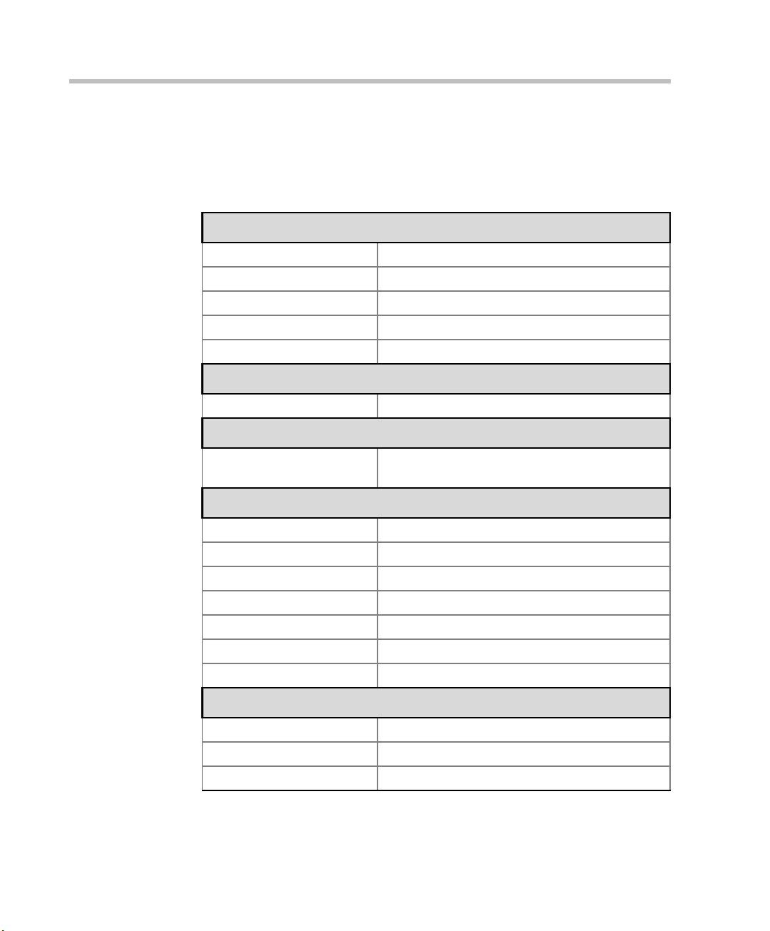
Table 1-1 lists the specifications of the MGC-25 unit.
Table 1-1: MGC-25 Unit Specifications
Physical
Height 2U (88.90 mm)
Width 19” (48 cm)
Depth 19” (48 cm)
Weight Up to 31 lb (14 kg)
Free space above MCU not required
Power Supply
AC Input 100–240 VAC, 50/60 Hz
Power Consumption
AC Maximum Power
consumption
Environment
Operating temperature 10°–40°C (50°–104°F)
Storage temperature -40°–70°C (40°–158°F)
Relative humidity 15%-90% no condensing
Operating altitude Up to approx. 3,000 m (10,000 ft.)
Storage altitude Up to approx. 12,000 m (40,000 ft.)
Operating ESD +8 kV
Storage ESD +15kV
Diagnostics
Power up Yes
On-line Yes
Remote Yes
AC Voltage–up to 2 AMP at 100 VAC, 1 AMP at
240 VAC
1-4
Page 13
Chapter 1 - Before You Begin
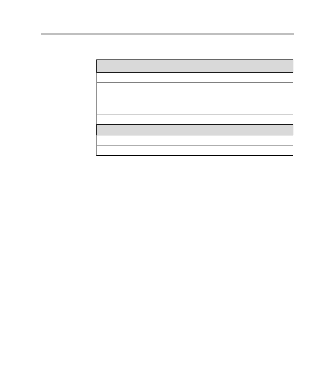
Table 1-1: MGC-25 Unit Specifications
External Communications
Data rates 6 Kbps–1920 Kbps (E1)
Network interfaces ISDN: T1 PRI, E1 PRI, Multirate ISDN (H0),
NFAS, Leased Lines: T1/E1
T1-CAS lines
H.323 & SIP: LAN
Clock synchronization Synchronizes to external network
Local/Remote External Equipment
Operator workstations LAN/RS-232/Modem/Internet
Reservation systems LAN/Internet/Modem
1-5
Page 14

MGC-25 Getting Started Guide
1-6
Page 15
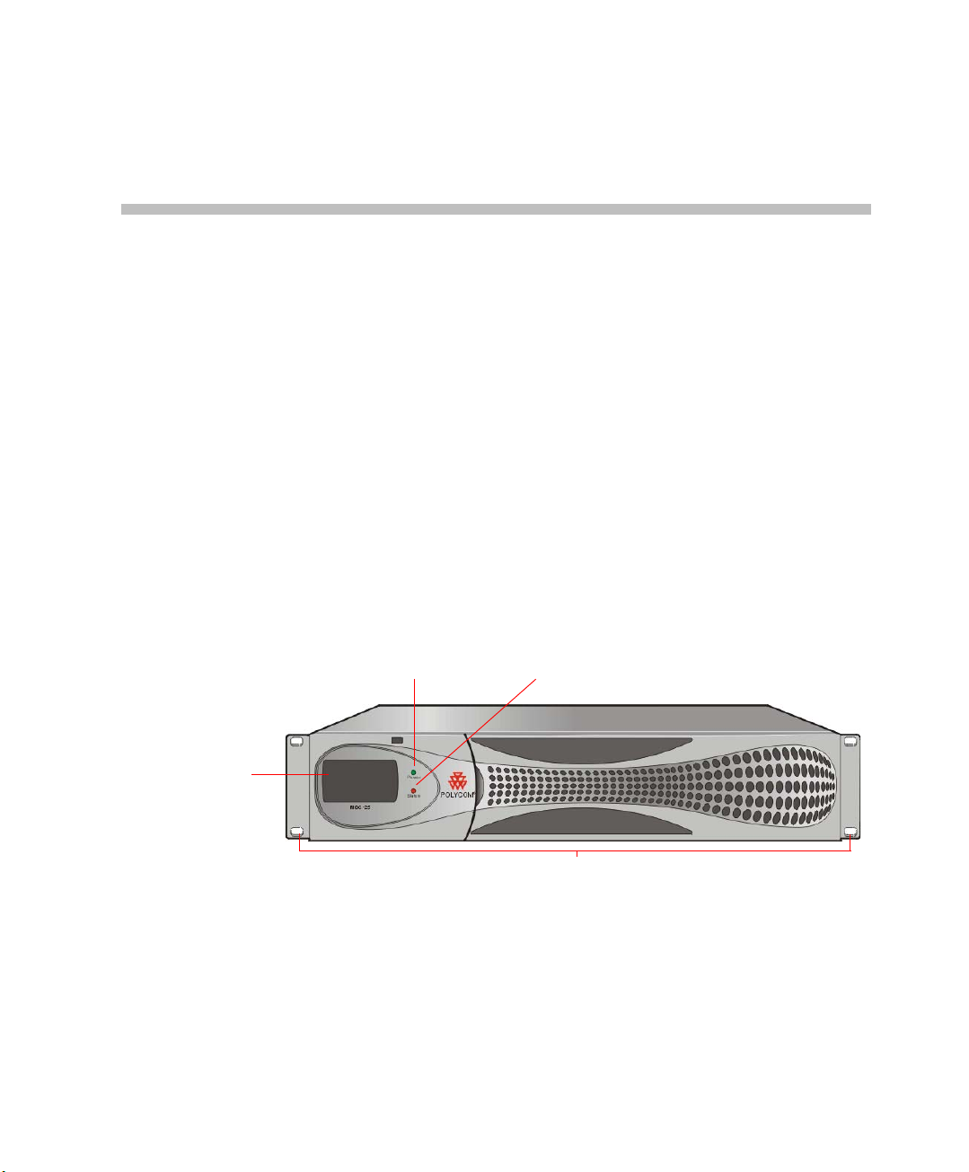
Hardware Description and
LCD Display
Window
Power LED indicator
Status LED indicator
Front brackets
Installation
Be sure to follow the safety precautions on page 1-2 before installing your
system.
Hardware Description
Front Panel
The MGC-25 front panel includes an LCD Display window which indicates
system and network statuses.
2
2-1
Page 16
MGC-25 Getting Started Guide
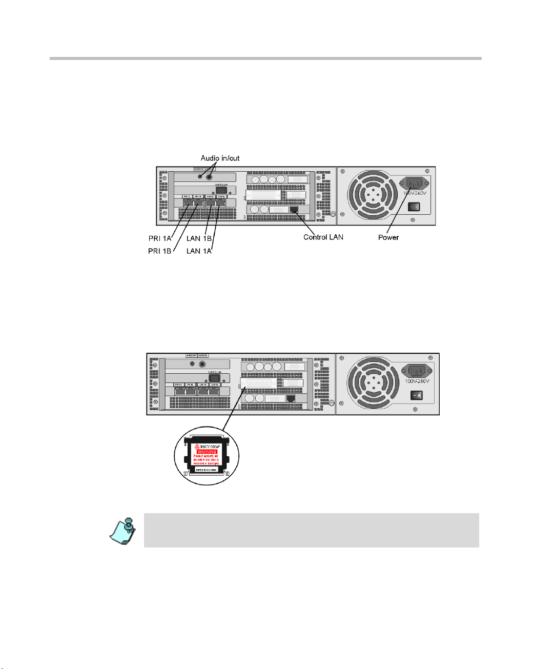
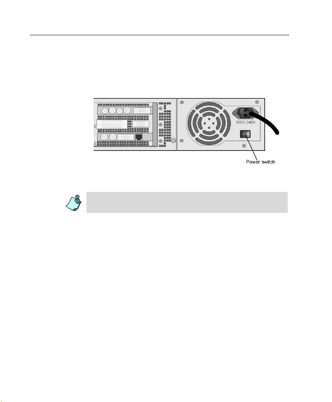
Rear Panel
The MGC-25 rear panel includes interfaces for two PRI connections, two
LAN connections, one Control LAN connection, a power cable, power
switch, cooling fan and interfaces for Polycom Support personnel.
Dongle
The Polycom MGC-25 Dongle is a hardware key that is installed in the
parallel port on the rear panel. This device contains configuration and
licensing data that is necessary for your system to function.
2-2
Never remove the dongle unless instructed by authorized support personnel.
Do not remove or damage the dongle label.
Page 17
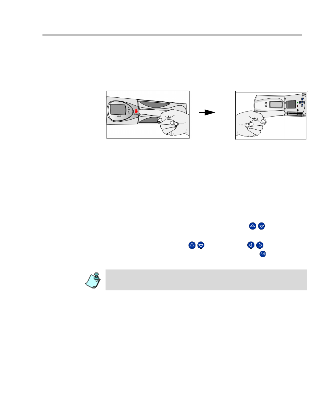
MGC-25 LCD Display Window
Open the panel door to access buttons for scrolling through the LCD screens
and configuring the system.
Working With the LCD Display Window
The LCD display window enables you to configure the MCU IP address and
view system status information without connecting to any external device.
The first time you use the MGC-25, the IP Configuration screen is displayed.
To navigate within an LCD Display:
Using the arrow buttons next to the LCD display window, you can navigate
within an LCD display to choose options, view system status, modify the
MCU IP address, save data and cancel parameter modifications.
Chapter 2 - Hardware Description and Installation
• To scroll vertically in a display, use the up/down ( /) buttons.
• On some displays, OK and Cancel options appear . To select one of these
options, use the up/down ( /) and left/right ( / ) buttons to
highlight the desired option and then press the Select ( ) button to
execute the operation.
When modifying the parameters on the IP Configuration display, navigation
works differently.
2-3
Page 18
MGC-25 Getting Started Guide
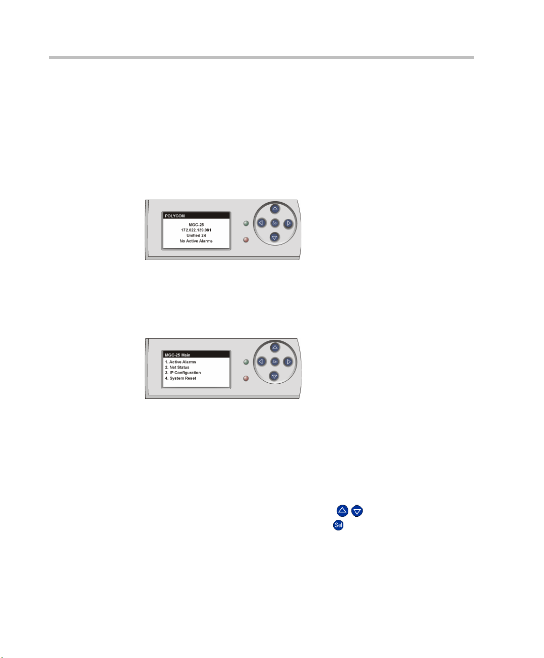
System Idle Display
When there are no actions being performed v ia the LCD Display or n o alarms
detected, the following information is displayed:
• Product Name
• IP Address
• Configuration Name
• Active Alarms Status
This display is shown whenever there have not been any actions performed
via the LCD Display for 30 seconds.
Main Menu
To access the Main Menu from the System Idle display, press any button.
2-4
The Main Menu in the LCD window includes four options:
• Active Alarms - displays network and system errors, if any
• Net Status - displays the status of each network connection
• IP Configuration - displays the IP address, Subnet Mask and Default
Gateway addresses. You can configure these values.
• System Reset - resets the system
T o access an option, scroll with the up/down ( / ) buttons until the desired
option is selected, and then press the Select ( ) button.
Page 19
Chapter 2 - Hardware Description and Installation
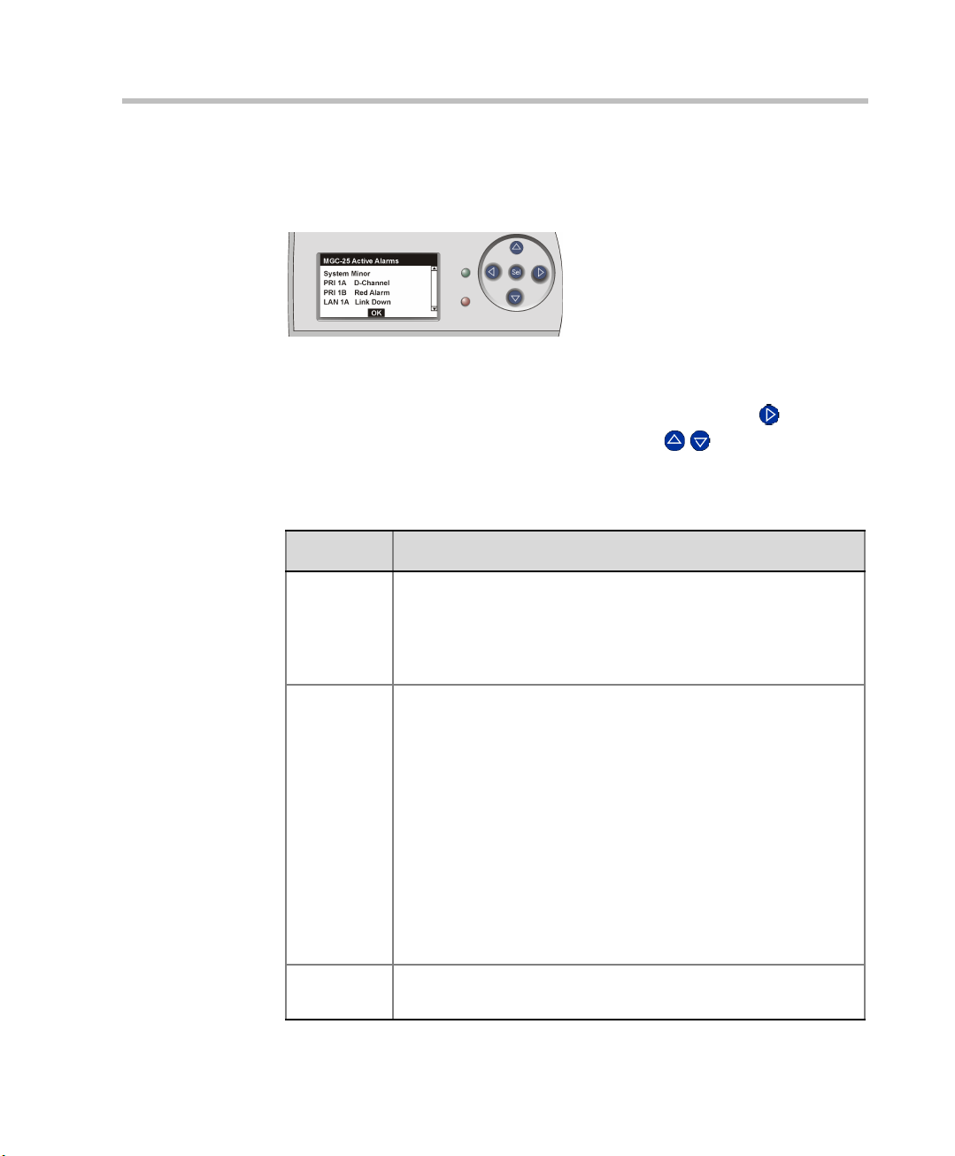
Active Alarms
To access the Active Alarms, select the first option from the MGC-25 Main
menu.
If there are no active alarms, selecting the Active Alarms option shows the
System Idle display.
To scroll vertically through the Active Alarms, press the right ( ) button to
highlight the scroll bar and then use the up/down ( / ) buttons to scroll.
The possible alarms are described in Table 2-1:
Table 2-1: Alarms Shown in the LCD Display Window
Alarm Type Description
System
Errors
PRI Errors R - Red Alarm
LAN Errors L - Link Down - There is no signal from the network.
Major/Minor Alarm
The system has an error. To view details about the error: in the
MGC Manager, right-click the MCU icon, and then click Faults.
For details about Faults, see the MGC Administrator’s Guide,
Chapter 5.
No connection is detected. There are no physical or higher layer
protocols established. The line cannot be used for service when
a red alarm is detected. Check the network cable .
Y - Yello w Al arm
The system is receiving a “Far End Alarm Failure.” This failure
indicates that layer 1 and layer 2 protocols have been
established but the layer 3 protocol is not yet established. The
line cannot be used for service when a yellow alarm is detected.
Check the network cable and contact your service provider.
N - Normal
D - D Channel not established.
Check the network cable and contact your service provider.
N - Normal
2-5
Page 20
MGC-25 Getting Started Guide
Table 2-1: Alarms Shown in the LCD Display Window
Alarm Type Description
Control
LAN errors
L - Link Down - There is no signal from the network.
N - Normal
T o return to the Main Menu, use the left/right ( / ) buttons to highlight the
OK option, and then press the Select ( ) button.
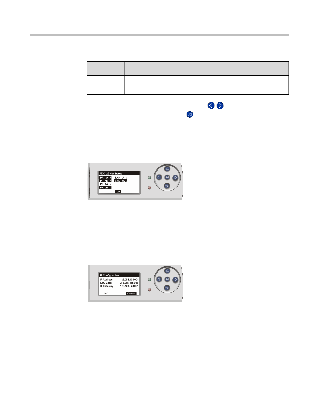
Net Status
The Net Status display lists all network links with their available statuses.
If there are no active alarms, selecting the Net Status op tion shows th e System
Idle display.
Network statuses are described in Table 2-1.
IP Configuration
The IP Configuration function is available in the Main Menu and is displayed
automatically the first time you access the system.
The IP Configuration display shows the IP address, Subnet Mask and Default
Gateway values of the system.
2-6
To modify these values, follow the instructions on page 3-1.
Page 21
Chapter 2 - Hardware Description and Installation
To save the values and reset the system, use the left/right ( / ) buttons to
select OK, and then press the Select ( ) button.
Alternatively, to return to the Main Menu without saving changes, use the
left/right ( / ) buttons to select Cancel, and then press the Select ()
button.
The OK option appears only if a component has been modified.
When the cursor is on the first component of the IP address, you can press the
left arrow button to access the OK and Cancel options.
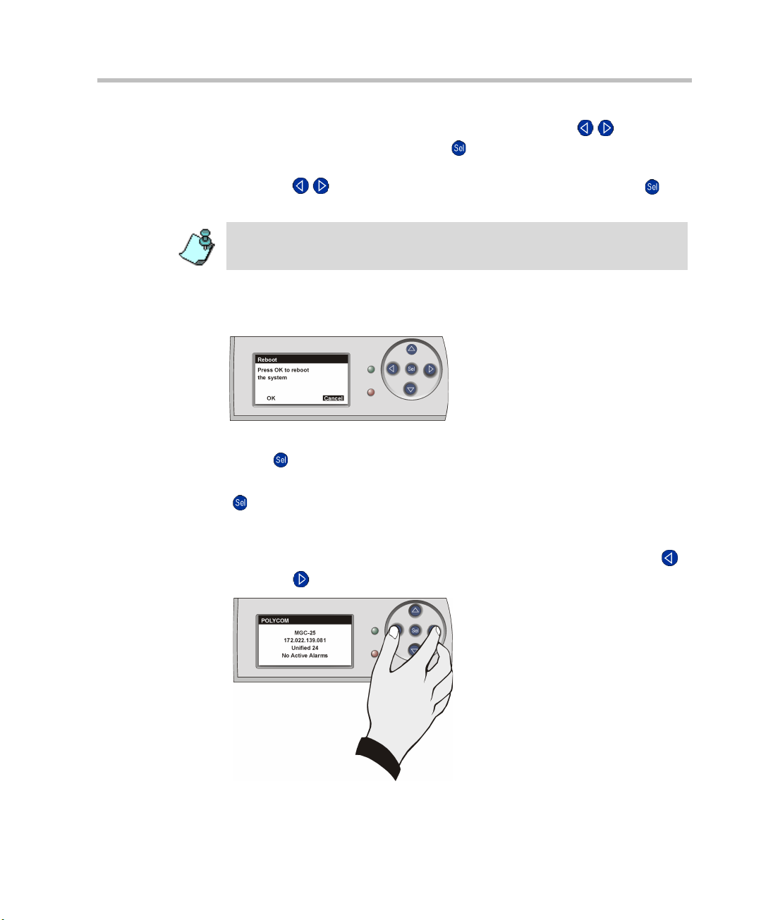
System Reset
The System Reset function is available from the Main Menu.
To reset the system, use the arrow buttons to select OK, and then press the
Select ( ) button.
To cancel, use the arrow buttons to select Cancel, and then press the Select
( ) button.
Manual System Reset
You can reset the system manually at any time by holding down the left ()
and right ( ) buttons simultaneously.
2-7
Page 22
MGC-25 Getting Started Guide
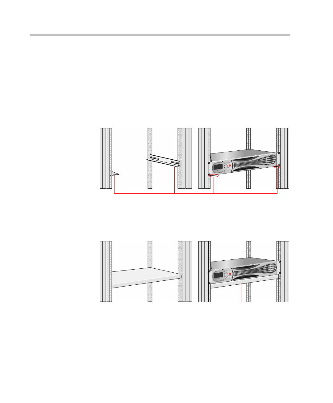
Place the system on brackets that have been installed
according to rack manufacturer specifications
Place the system on a shelf that has been installed
according to rack manufacturer specifications
Hardware Installation
Installing the MGC-25 in a Rack
There are two methods to install the system in a rack:
• Install brackets supplied by the rack manufacturer on each side of the
rack on which the MGC-25 is placed. Secure the system by fastening
four screws to the rack on the front panel.
2-8
• Install a shelf supplied by the rack manufacturer. Place the MGC-25 on
top of the shelf. Secure the system by fastening four screws to the rack
on the front panel.
Page 23
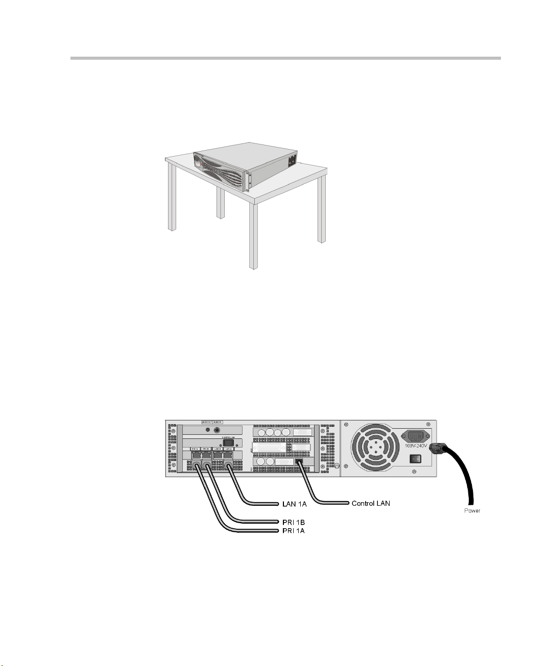
Placing the MGC-25 on a Desktop
Place the system on a secure, flat and clean surface and avoid placing
anything on top of the system.
Connecting Cables
Connect the following cables:
• Power cable - insert the connector firmly into the socket so that almost
all of the narrow section of the connector is inserted
• ISDN PRI or T1-CAS cables (optional)
• LAN network cable (optional)
• Control LAN cable (to the LAN network with MGC Manager PC)
Chapter 2 - Hardware Description and Installation
2-9
Page 24
MGC-25 Getting Started Guide
Powering Up the System
1. Make sure the power cable is connected to the system and to a grounded
power outlet.
2. Press the power switch to “1” to start the system.
On the front panel of the MGC-25 the power indicator LED and the LCD
Display Window flash. The system startup may take up to five minutes.
Wait at least 10 seconds between turning the system off and turning it on. If you
turn the system off and then try to turn it on right away, the system will not allow
powering up for one minute.
2-10
Page 25
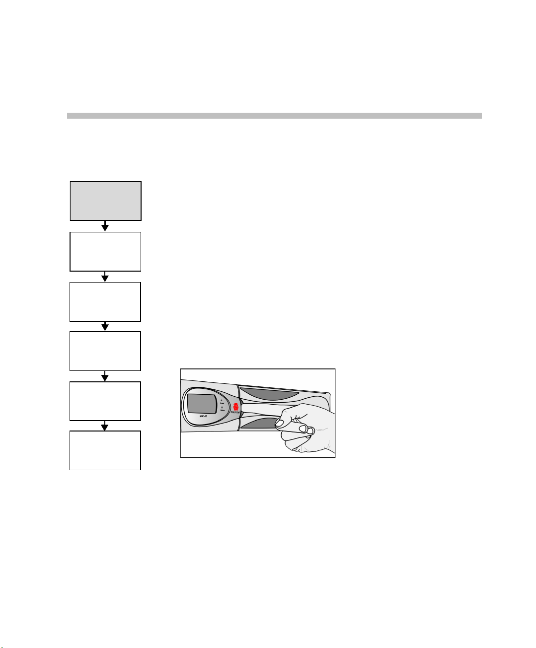
Installing the
MGC Manager
Initial IP
Configuration
Connecting
to an MCU
Configuring the
Network Services
Defining an MCU
Starting the MGC
Manager
3
Initial System Setup
The MGC-25 requires basic configuration before you can start running
conferences.
Initial IP Configuration
The system is shipped with a default IP address: 129.254.4.8. Whe never the
system is turned on, the system checks the IP address. If the currently
defined IP address is 129.254.4.8, the system assumes that it has not been
configured and shows the IP Configuration parameters on the LCD window.
You can now enter the IP address allocated to the MCU using the LCD and
the arrow keys.
To configure the IP address of the MGC-25:
1. Open the panel for the LCD as shown:
The IP Configuration is displayed.
3-1
Page 26
MGC-25 Getting Started Guide
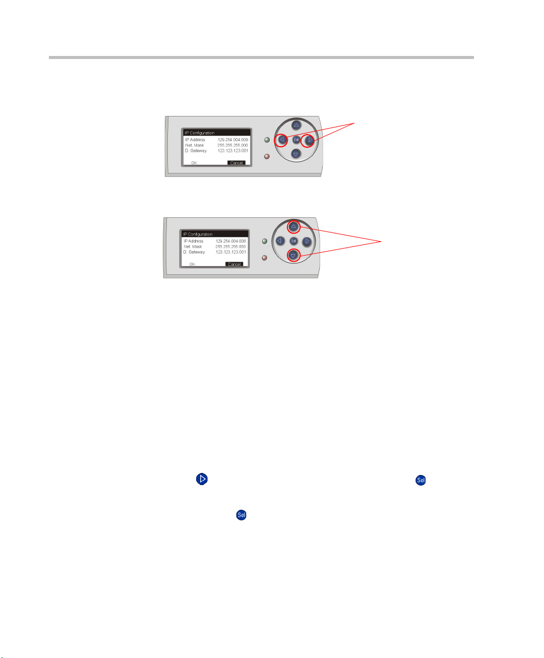
Left/Right Buttons
Up/Down Buttons
2. Start by modifying the IP Address.
3. Using the up/down buttons, modify the numb er. The number value range
4. After modifying a component, press the Right arrow button to move to
5. Repeat steps 2 to 4 to modify the remaining components of the IP
Using the Left/Right buttons, move to the desired number to modify.
is 0-255. To scroll through the numbers by tens, keep the button pressed.
the next component to modify. Press the Left arrow button to return to a
previous component.
address.
3-2
6. Press the Right arrow button to move to the Subnet Mask IP number. The
Subnet Mask is assigned values according to the IP address entered.
If you do not want to modify the Subnet Mask, press the Right arrow
button until you reach the Default Gateway number. If no additional
changes are required, skip to step 8.
7. Enter the IP address of the Default Gateway if the MCU is connected to a
network other than the one used by the PC running the MGC Manager.
8. After completing the modifications of all numbers, press the Right arrow
button ( ) until OK is selected, and then press the Select ( ) button.
A notification that the system will be reset is displayed.
9. Press the Select ( ) button to reset the system.
Page 27
Installing the
MGC Manager
Initial IP
Configuration
Connecting
to an MCU
Configuring the
Network Services
Defining an MCU
Starting the MGC
Manager
Chapter 3 - Initial System Setup
Installing the MGC Manager
To set up conferences and to control the MGC unit you must install the MGC
Manager software on a PC. Up to 30 MGC Manager-enabled PCs can be
connected to each MGC-25. A single MG C Manager -enabled PC can manage
multiple MGC systems.
During the installation, default Reservation templates are installed.
The MGC-25 is shipped with a default IVR Service, default Entry
Queue Service, and a default conference profile. For information
about restoring these services when upgrading MCU software, refer
to the MGC Administrator’s Guide, Chapter 5.
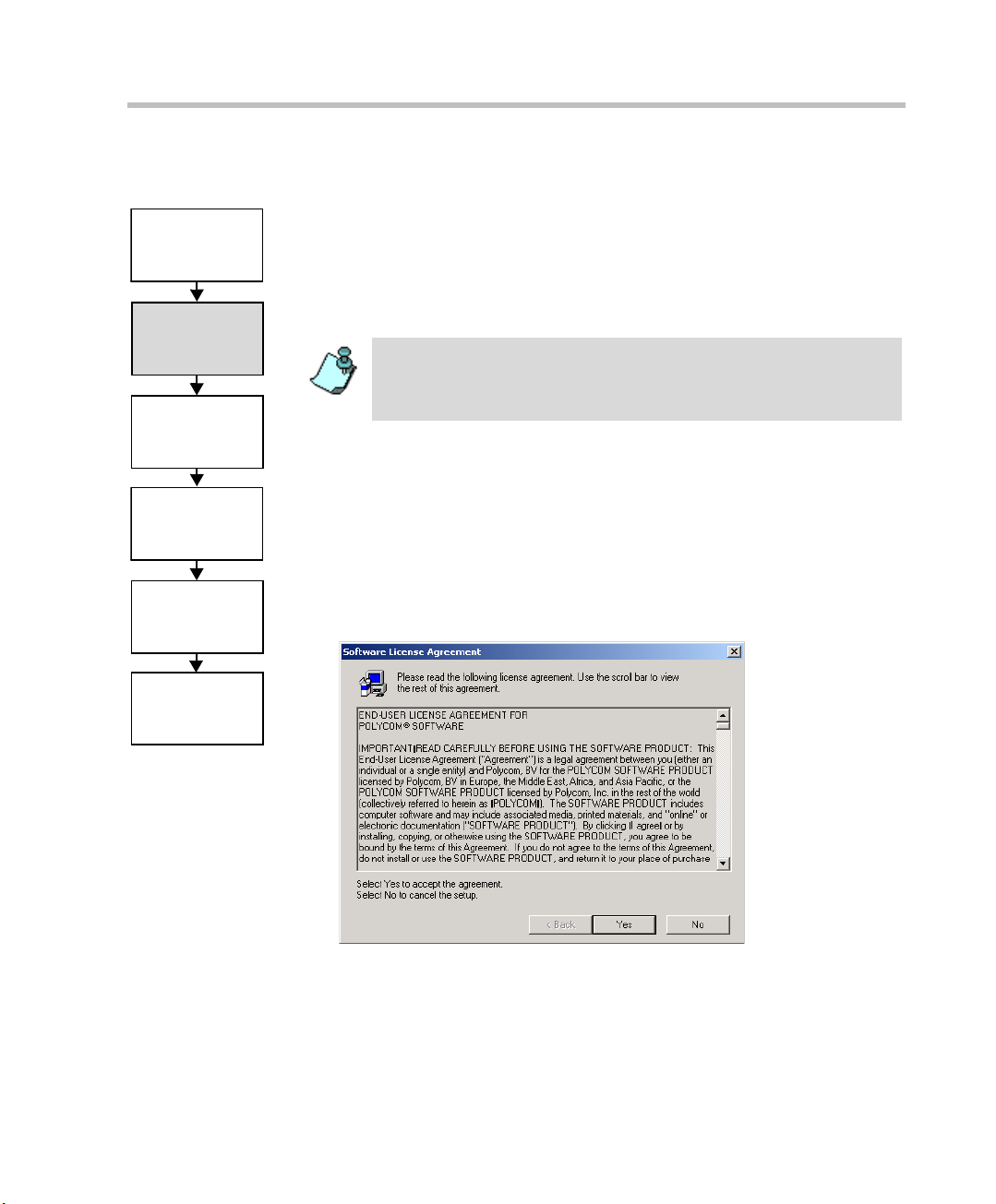
To install the MGC Manager software:
1. Insert the software CD into the CD drive.
2. On the Start menu, click Run.
The Run dialog box opens.
3. Type D:\SETUP (where D is the name of the CD drive), and then click
OK.
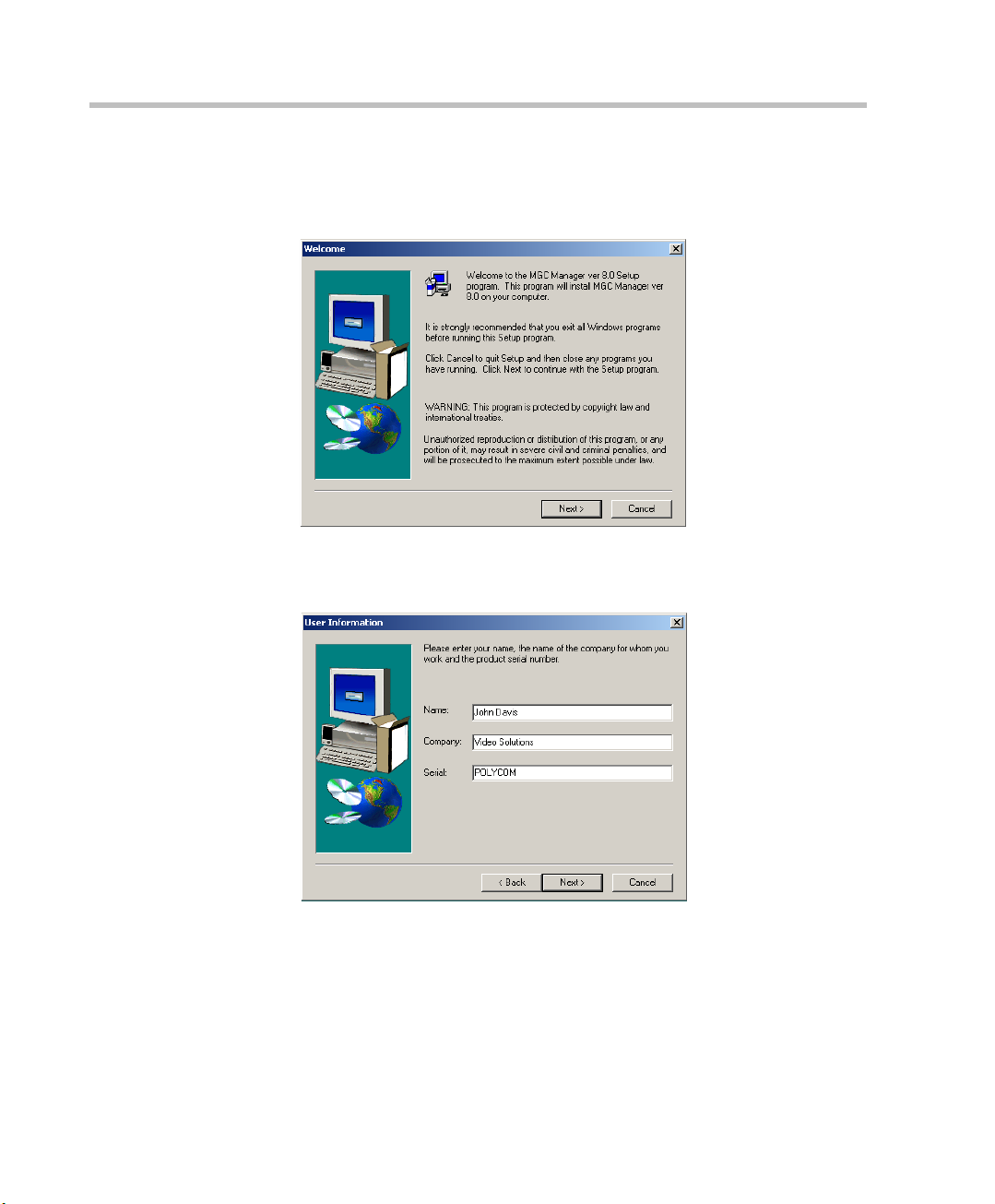
The installation wizard starts and the License Agreement window opens.
3-3
Page 28
MGC-25 Getting Started Guide
4. Click Yes to agree to the terms of the agreement or No to exit the
5. Click Next.
installation.
If you clicked Yes, the Welcome window opens.
The User Information screen opens.
3-4
6. Enter your name and the name of your company in the appropriate
boxes.
For a standard installation, en ter Polycom in the Serial box.
7. Click Next.
Follow the on-screen instructions to complete the installation process.
Page 29
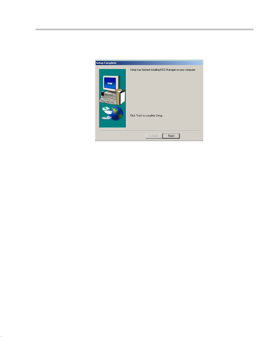
Chapter 3 - Initial System Setup
At the end of the installation procedure, the Setup Complete window
opens.
8. Click Finish.
The MGC Manager software is now installed on your computer.
3-5
Page 30
MGC-25 Getting Started Guide
Installing the
MGC Manager
Initial IP
Configuration
Connecting
to an MCU
Configuring the
Network Services
Defining an MCU
Starting the MGC
Manager
Main Menu
Toolbars
Status pane
Monitor pane
Browser
pane
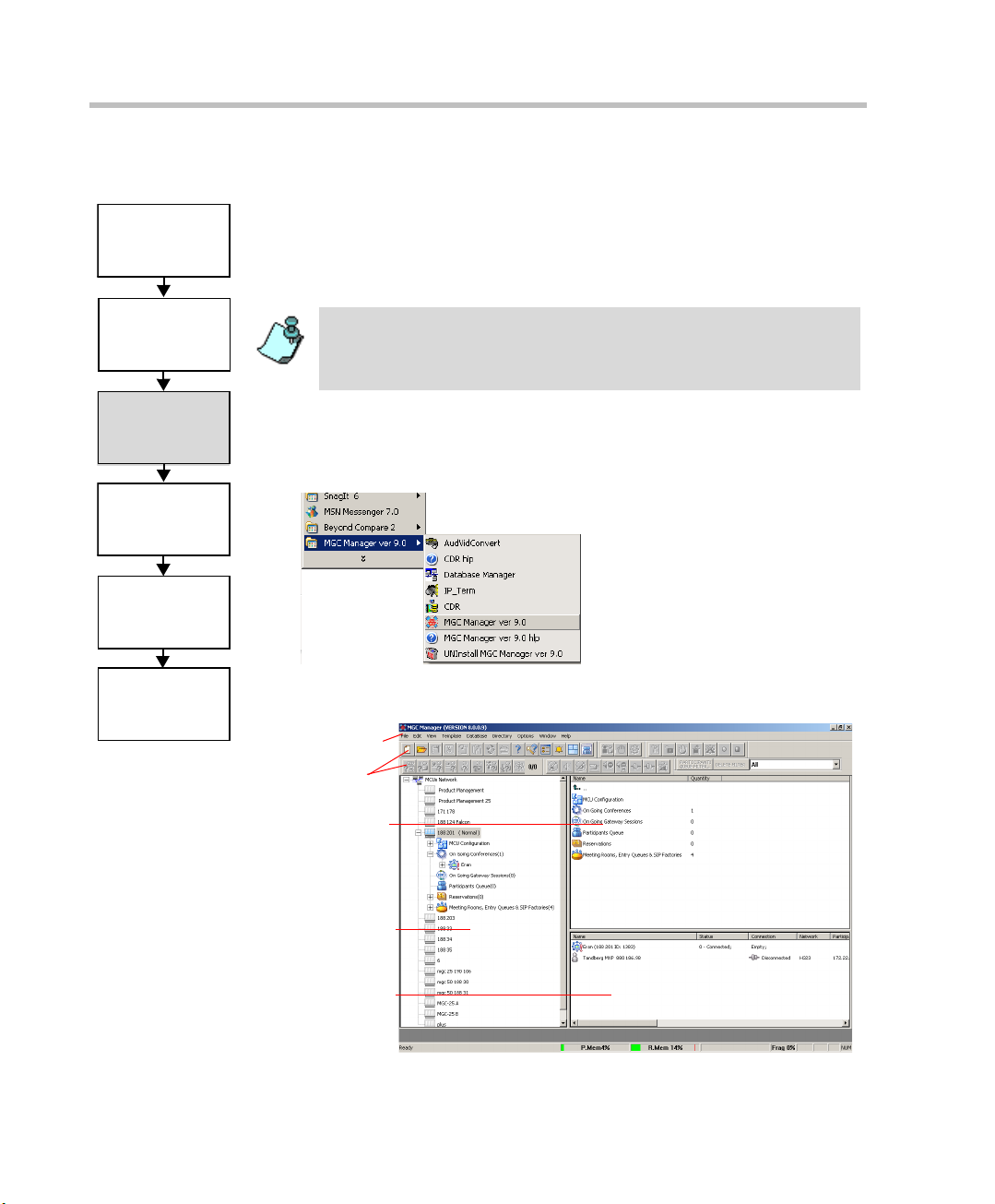
Starting the MGC Manager
The MGC Manager can connect to several MGC units simultaneously. The
first time you run the MGC Manager application, or when a new MCU is
added to your configuration, you must first define each MCU’s IP address and
listening port number.
The MGC unit has to be installed and its IP address properly configured
before defining its connection parameters in the MGC Manager
application. For details, see “Initial IP Configuration” on page 3-1 in this
guide.
To define an MGC connection:
• On the Start - Programs menu, click MGC Manager ver 9.0, and then
click MGC Manager ver 9.0 to start the application.
3-6
The MGC Manager main window opens.
Page 31

Installing the
MGC Manager
Initial IP
Configuration
Connecting
to an MCU
Configuring the
Network Services
Defining an MCU
Starting the MGC
Manager
Chapter 3 - Initial System Setup
Defining an MCU
To define a new MCU:
1. In the Browser pane, right-click the MCU Network icon, and then click
New MCU.
The Add MCU dialog box opens.
2. In the Name box, enter the name of the MCU, using up to 20 characters
(no comma, period or semicolon). Specify a name that clearly identifies
the MCU.
3. In the IP Address box, enter the IP Address of the MCU.
The IP address should be identical to the one configured in the LCD
Display during the Initial IP Configuration settings.
4. Click OK.
The Add MCU dialog box closes. A new icon with the specified MCU
name appears in the Browser pane listed below the MCUs Network icon.
3-7
Page 32

MGC-25 Getting Started Guide
Installing the
MGC Manager
Initial IP
Configuration
Connecting
to an MCU
Configuring the
Network Services
Defining an MCU
Starting the MGC
Manager
Connecting to an MCU
Once the MCU connection parameters are defined, the MGC Manager can be
connected to all defined MCUs simultaneously. The MGC Manager allows
you to set up conferences, make reservations, monitor On Going Conferences
and perform other activities on several MCUs. The MGC Manager reports the
status of each MCU connect ion.
To connect the operator workstation to an MCU:
1. In the Browser pane, expand the MCUs Network tree.
A list of MCUs appears below the MCUs Network icon.
2. Double-click the MCU icon.
Alternatively, right-click the MCU icon, and then click Connect.
The Logon dialog box opens.
3. Enter your Login Name and Password, and then click OK.
Each MCU is initially configured with a default operator whose Login and
Password are both POLYCOM. Additional operators can be defined . For more
details, see the MGC Administrator’s Guide, Chapter 6.
3-8
Page 33

Configuring the
Network Services
Installing the
MGC Manager
Initial IP
Configuration
Connecting
to an MCU
Defining an MCU
Starting the MGC
Manager
Chapter 3 - Initial System Setup
Configuring the Network Services
If no Network Services have been configured, depending on your system
configuration, an appropriate Network Configuration dialog box is
automatically displayed.
• If your system is configured to work with both IP and ISDN, the Network
Configuration Wizard dialog box is displayed. This section describes the
configuration of both IP and ISDN Network Services.
• If your system is configured to work with IP only, the IP Configuration
dialog box is displayed. For details, see page 3-10.
• If your system is configured to work with ISDN only, the ISDN
Configuration dialog box is displayed. For details, see “To configure an
ISDN Network Service:” on page 3-13.
Network Configuration Wizard
The Network Configuration Wizard enables you to set up the ISDN and IP
network services quickly.
For information about defining T1-CAS Network Services, defining
additional ISDN or IP Network Services, adding advanced definitions or
modifying existing Network Services, refer to the MGC Administrator’s
Guide, Chapter 3.
You can access the Network Configuration Wizard any time from the MCU
right-click menu.
3-9
Page 34

MGC-25 Getting Started Guide
You can start the configuration process in any order, by clicking the
appropriate Network button.
To route Meet Me H.323 dial-in participants to their conferences, some
gatekeepers require configuration of an IP Network Service prefix. If your
gatekeeper requires the definition of a prefix, configure it in the gatekeeper
before you define the IP Network Service.
To configure the IP Network Service:
1. In the Network Configuration Wizard window, click the IP button.
The IP Configuration dialog box opens.
3-10
Page 35

2. Define the following parameters:
Table 3-1: IP Configuration Parameters
Field Description
Chapter 3 - Initial System Setup
IP Service
Name
Obtain IP
Address
Automatically
(DHCP)
LAN 1A
Spans
Configuration
LAN 1 IP
Address
Subnet Mask Enter the subnet mask of the MCU’s IP card. If the
Default Router Enter the IP of the default router in this box. If a DHCP is
Enter a name using up to 20 characters, or use the
default name (IP Default Service).
Select this check box to use a DHCP server for
automatic assignment and tracking of IP addresses to
the conference devices.
Do not select this check box if you need to establish a
static IP address, for example, when working with a
firewall and you need to translate an internal IP address,
that must be static, with an external one.
Select this check box to indicate that a LAN span is
connected to the IP card in the MCU and to define the
properties of this card.
Enter the IP address of the IP card installed in the MCU.
When the DHCP server is used, the IP address of the
card appears as 0.0.0.0.
DHCP is used, the subnet mask is automatically
retrieved from the DHCP server and cannot be
modified.
The detected number appears in the card’s
Properties-Settings-IP Network Parameters box.
used, the IP address of the default router is
automatically retrieved from the DHCP server and
cannot be modified.
DNS DNS — Select this check box to indicate that a DNS
server is used in the network and then select:
• Specify — to enter the IP address of the DNS
server.
• Auto — to automatically detect the primary DNS IP
address, provided the DNS Server is defined in the
DHCP and if the DHCP -obtain IP Address
Automatically check box was selected.
3-11
Page 36

MGC-25 Getting Started Guide
Table 3-1: IP Configuration Parameters (Continued)
Field Description
DNS Server IP
Address
If DNS – Specify was selected, this field is mandatory.
Enter the IP address of the primary DNS server to be
used for name translation.
Local Domain
Name
Enter the domain name where the MCU is installed.
The name of the domain includes the host part of URL
or URI, for example, polycom.com.
This field is used both for SIP proxy registration and
DNS resolution and therefore it is required if you are
using DNS servers in this service.
H.323 Select this option if this Network Service will be used to
connect to H.323 participants.
Gatekeeper Select this checkbox if a gatekeeper is used with this
Service.
Gatekeeper IP
Address or
Name
Enter either the gatekeeper’s host name (if the DNS
server is enabled and the gatekeeper is registered with
the DNS), or IP address.
LAN 1 H323 ID The H.323 identification is a number used to identify the
card’s span. It can be any whole number between 0 to
65535. This number is assigned to a specific IP address
and must be unique per MCU.
Prefix Enter the prefix that is used when registering the MCU
with the gatekeeper (when applicable). This prefix is
used by H.323 participants as part of the dialing string
when connecting to the MCU.
3-12
SIP Select this check box if this Network Service will be
used by SIP participants to connect to the MCU. Then
select:
Specify—to manually define the SIP server.
Auto— to automatically detect the SIP server’s IP
address if a DHCP or if a DNS Server is present and
defined.
SIP Server IP
Address or
Name
If SIP – Specify was selected, enter either the IP
address of the preferred SIP server or its host name (if a
DNS server is used)
Page 37

Chapter 3 - Initial System Setup
Table 3-1: IP Configuration Parameters (Continued)
Field Description
Domain Name
or IP Address
Conferences and Entry Queues can be registered in the
proxy in the format user@host. for example,
EQ1@polycom.com.
When dialing to a conference or Entry Queue, the SIP
server expects to receive the host either as domain
name or as an IP address.
3. Click OK.
If your system supports only IP networks, a confirmation message is
displayed.
4. Click OK to confirm.
If you are defining only the IP Network Service, the Network Configuration
dialog box closes and the new IP Network Service appears in the IP Network
Services list. You must reset the MCU.
If you are defining both IP and ISDN Network Services, the Network
Configuration Wizard dialog box is displayed.
To configure an ISDN Network Service:
1. Click the ISDN button.
3-13
Page 38

MGC-25 Getting Started Guide
3
4
5
6
7
2
The ISDN Configuration dialog box opens.
2. In the ISDN Service Name box, enter a name or use the default name
(ISDN Default Service).
3. Select the PRI 1A check box to define the parameters of the first ISDN
span.
4. If a second span is connected to the MCU, select the PRI 1B check box.
5. From the Line Type drop-down list; select either T1 (usually in the U.S),
or E1 (usually in Europe).
6. From the Switch Type drop-down list, select the brand and revision level
of equipment installed in the telephone company’s central office.
7. In the Dial-In Numbers Range boxes, enter the phone numbers to be used
for dial-in connections as allocated to the MCU by your service p rovider.
Enter the first and last numbers in the range of phone numbers.
8. Click OK.
A confirmation message is displayed.
3-14
Page 39

Chapter 3 - Initial System Setup
9. Click OK.
The Network Configuration dialog box closes and the new Network
Services appear in the Network Services list. These Network Services
automatically set as the default services.
The following icons are used to indicate the Network Service types:
Table 3-2: IP Network Service Icons
Icon Description
The Network Service supports both SIP and H.323
connections.
The Network Service supports only H.323
connections.
The Network Service supports only SIP connections.
The Network Service supports only ISDN
connections.
The Network Services definition is complete.
For advanced settings, see the MGC Administrator’s Guide, Chapter 3.
3-15
Page 40

MGC-25 Getting Started Guide
Modifying Network Services
T o make changes in the IP and ISDN configuratio ns, right-click th e MCU and
select Fast Configuration Wizard. The Network Configuration Wizard
window opens.
To change IP configurations click the IP button. To change ISDN
configurations click the ISDN button. For information regarding the
configurable fields in the relevant dialog boxes see “Network Configuration
Wizard” on page 3-9. For additional information abut setting the Network
Service as default, see the MGC Administrator's Guide, Chapter 3, “Setting
the Default Network Service”.
3-16
Page 41

Conference Types
Different conference types are available according to their initiation modes:
reservationless conferences and scheduled conferences.
On-demand Conferences (Reservationless Conferencing)
Reservationless conferencing enables you to immediately start and connect
to On Going conferences from your endpoint, with no advance d schedul ing.
The MGC Manager offers two methods for Reservation-less conferencing:
• Ad Hoc Conferencing
• Meeting Rooms
Ad Hoc Conferencing
4
In Ad Hoc conferencing, the participant connects to an Ad Hoc-enabled
Entry Queue. An Entry Queue is a special routing lobby to which one or
more dial-in numbers are assigned. The participant is prompted for the
destination conference Num eric ID. If no conference with a matching
Numeric ID is running, the system creates a new On Going conference,
provided the participant has the permission to do so. The new conference is
created according to the conference parameters defined in a Profile assigned
to the Entry Queue. In this method, the conference Profile is created only
once, and is used repeatedly to create numerous conferences.
This conferencing method is often used to globally enable all employees in
an organization to start On Going Conferences from their endpoints, without
having to define the conference parameters for each employee and for each
conference.
When authentication with external database application is configured for the
Entry Queue and for the conference, the MCU verifies with the external
4-1
Page 42

MGC-25 Getting Started Guide
database application whether a conference with a specific Numeric ID may be
started. This is the method used with Windows Messenger and Office
Communicator to initiate multipoint Video or Audio conferences.
For more information about Ad Hoc conferencing, see the MGC Manager
User’s Guide, Volume II, Chapter 3.
Meeting Rooms
Meeting Rooms are conferences created once, with no starting date or time,
no reserved resources and it can be activated as many times as required. The
Meeting Room remains in passive mode until the first participant connects to
it and activates the conference. To start the conference you simply let the
participants know the start date and time, dia l-in nu mb er and the Numeric ID
of the conference. No prior booking is required. The conference returns to
passive mode once the conference ends and remains in the MCU memory
until the next activation. In this mode, a Mee ting Ro om is usual ly defin ed for
each of the employees in your organization. This may require tedious work
when your organization inclu des many employees, and it also loads the MCU
memory with all the saved Meeting Rooms.
Scheduled Conferences
You can define a conference to start at a certain date and time or to start
immediately. Scheduled conferences run once and are then deleted from the
MCU memory. For scheduled conferences, the MCU reserves resources for
the conference participants, provided the participant endpoints are defined
during the conference definition. You can define conferences without
defining their participants and let participants connect to the conference as
long as there are resources available.
4-2
Page 43

Video Conference Attributes
There are four general types of video conferences:
• Video Switching - A conference in which all participants use the same
video and audio formats. Whenever a participant starts to speak, the
participant appears on all endpoints in full screen display as the
conference is a voice activated video switching conference.
• Transcoding (requires Video card) - A conference in which participants
use different video, audio and data formats, while maintaining the
highest video and audio capability each participant can achieve with his
or her codec. Like video switching, the current speaker is displayed on
all endpoints in full screen.
• Continuous Presence (requires Video card) - A conference in which
several participants can be viewed simultaneously. In this type of
conference, the highest video, audio and data quality for each partic ipant
depends on the participants endpoint capabilities.
In a traditional Contin uous Presence conference, each participant uses a
different video port on the Video card. This method enables such features
as full Transcoding per participant, Personal Layouts (individualized
Continuous Presence layouts per participant) and maintenance of overall
video and audio quality for the confer ence—even when participants with
lower capabilities connect. However, this method limits the number of
Continuous Presence participants to the number of ports on the Video
card, which is six.
• Conference On Port (requires Video card) - A conferencing method
suitable for large Continuous Presence conferences or when several
Continuous Presence conferences are running on the MCU.
In Conference On Port, all conference participants use a single video
port. This method allows for more than six participants to join a
Continuous Presence conference and allows fo r up to six Continuous
Presence conferences to be run on the MCU.
In a Conference on Port conference, a video layout can be selected for
the conference, but all the participants, including the speaker, view the
same layout and the same participants. The Personal layout selection is
not available in Conference on Port and the video quality is determined
by the highest common video parameters and by the video line rate.
Chapter 4 - Conference Types
4-3
Page 44

MGC-25 Getting Started Guide
Entry Queue
An Entry Queue is a special routing lobby that is used for routing participants
to their target conferences. One or several dial -in numbers are assigned t o the
Entry Queue, and they are used by callers to all conferences. Once callers are
connected to the Entry Queue, they are routed and connected to the target
conferences if they provide the appropriate conference IDs and passwords
(optional). Both Video and Audio Only conferences can be accessed from an
Entry Queue. For information about defining an En try Queue, see Chapter 6,
“Defining a New Audio Only Entry Queue” on page 6-1 or Chapter 7,
“Defining a New Video Entry Queue” on page 7-1.
4-4
Page 45

Basic Operation
This chapter describes how to start, monitor and manage On Going
Conferences.
Reservation Templates
A Reservation template includes the conference parameters, such as the
conference media (audio, video), video session type, line rate, video
protocol and other video parameters, IVR and more. The reservation can
include the conference participant parameters.
Default Reservation Templates
Five default Reservation templates are installed with the MGC Manager:
• Default-Audio: Audio Only with Default IVR service
• Default_COP: Conference On Port at 384 Kbps
• Default_Video: Continuous Presence Conference at 384 Kbps
• SW CP: Software Continuous Presence (H.323 only) at 384 Kbps
• Video-Switch: Video Switching at 384 Kbps
5
In order to run a Default_Video or Default_COP conference, the Video+ card
and MGC Version 5.6 or later must be installed in your system.
Using the default Reservation templates, you can schedule a conference to
start immediately (On Going Conference), or to start automatically at a
predefined date and time (Reservation). For details of the default
Reservation templates parameters, see “Appendix A: Default Templates”.
5-1
Page 46

MGC-25 Getting Started Guide
Starting a Conference
You can start an On Going Conference from one of the default Reservation
templates provided with the system, or you can define a new On Going
Conference. For more details about defining new conferences, see “Defining
a New Audio Conference” on page 6-1 or “Defining a New Video
Conference” on page 7-1.
To start an On Going Conference from a default Reservatio n template :
1. Connect to an MCU. For more details, see “Connecting to an MCU” on
page 3-8.
2. The Default folder in the Reservations Database window opens
automatically when you open the MGC Manager. Otherwise, access this
window by clicking Reservations in AccordDB from the Window
menu.
5-2
The Reservations Database window opens.
If the Reservations Database window did not appear automatically and is not
included in the Window menu options, reopen this window using the login
procedure described in the MGC Manager User’s Guide, Volume I, Chapter 3,
MGC Manager Basics.
3. In the Reservations Database window, expand the Default folder to
display the list of default Reservation templates.
Page 47

Chapter 5 - Basic Operation
4. Right-click the icon of the appropriate Reservation template to start, and
then click Start Immediately. If more than one MCU is connected,
select the name of the MCU to run the conference from the pop- up list.
The conference begins and appears in the list of On Going Conferences.
If no participants were defined in the Reservation template, the
conference starts but contains no participants.
5-3
Page 48

MGC-25 Getting Started Guide
Viewing the Conference Dial-in Properties
The dial-in numbers and passwords needed to enter a conference, including IP
Network Prefixes and Numeric IDs appear in the MGC Manager Status pane.
To view the list of On Going Conferences and their dial-in numbers:
• Expand the MCU tree, and then click the On Going Conferences icon.
The list of On Going Conferences with their Numeric IDs and dial-in
numbers are displayed in the Status pane.
In some configurations, the ISDN/PSTN number is truncated by the PBX, and
you must add the appropriate prefix to the dial-in number that is displayed in
the Status pane.
5-4
Page 49

Chapter 5 - Basic Operation
Connecting to a Conference/Entry Queue
Defined dial-in participants can connect to any conference by dialing the
conference dialing string (I SDN, H.323 or SIP). The MCU identifies their
CLI or IP address (as defined in the participant prop erties) and ro utes them to
the appropriate conference. Dial-out participants must be defined in the
conference.
Undefined participants can connect directly to conferences defined as Meet
Me per Conference or Meeting Room by dialing its dial-in string. If required,
the participants enter the conference password before joining the conference.
Undefined participants can also connect to a single-dial Entry Queue to
access conferences. The dialing methods are the same as for the conference.
Once participants connect to the Entry Queue, they are routed to their
conference according to the conference numeric ID or password that they
enter.
In the default templates, just the Audio Only template is defined with Entry
Queue Access. To create a new video conference with Entry Queue Access,
see “Creating an On Going Video Conference” on page 7-6.
Dialing-in to a Conference/Entry Queue
Undefined dial-in participants can access the conference using the following
methods:
ISDN/PSTN Participants
Audio Only, PSTN and ISDN Video participants dial the conference/Entry
Queue ISDN dial-in number, as assigned to the conference Entry Queue by
the operator or automatically by the MCU. The dial-in number can be viewed
in the MGC Manager Status pane.
H.323 Participants
When a gatekeeper is present, H.323 participants dial: the [IP Network
Service Prefix] and [conference/Entry Queue Numeric ID or name] for
example, if the Network Service prefix is 925 and the Conference Numeric
ID is 1222, participants will dial 9251222. If participants dial only the
Network Service Prefix, or if the wrong numeric ID i s dialed, participants will
be automatically routed to the defa ult Entry Queue if one is defi ned. For more
information about the IP Network Service Prefix, see Chapter 3.
5-5
Page 50

MGC-25 Getting Started Guide
For example, if the IP Network Service prefix is 27, the conference Numeric
ID is 1478 and the conference name is ‘MARKETING’, the participant can
dial 271478 or 27MARKETING. IF the Entry Queue name is EQ1 and its
numeric ID is 3000, the participant can dial 273000 or 2 7EQ1 to access the
MR. IF only 27 is dialed, participants are be routed to the defaul t Entry Queue
(if one is defined).
When no gatekeeper is present, H.323 participants dial the IP address of the
MCU’ s IP card, followed by ## and the conference/Entry Queue Numeric ID.
For example, if the IP card address is 172.22.190.162, participants will enter
172.22.190.162##1478 to access the con ference, or 172.22 .190.162##3000 to
access the Entry Queue.
If no Entry Queue /conference numeric ID or if the wrong numeric ID is
entered, participants are be routed to the default Entry Queue (if one is
defined). If no default entry queue is defined in the system, the call is
disconnected.
SIP participants
When a new conference reservation or Entry Queue is defined the conference
or Entry Queue registers with the SIP proxy.
SIP participants dial the conference/Entry Queue URI using the format:
Conference or Entry Queue name@domain name.
For example, MRO1@polycom.com, or EQ1@polycom.com.
Usually for SIP conferencing, an Ad Hoc Entry Queue is used. In this
scenario, the first participant dials the Entry Queue and creates a new
conference, while the other conference participants dial directly to the
conference using the conference name or Numeric ID.
When dialing from a Microsoft Windows Messenger endpoint that does not
have DTMF capabilities, the first pa rticipant (who creat es the new conference
in Ad Hoc Conferencing) enters the Entry Queue name followed by the target
conference name and the numeric ID in the format:
EQ Name(Target Conference Name)(Target Conference Numeric ID).
For example, EQ1(sales)(12345). In this example, the Entry Queue name is
EQ1, and a new On Going Conference by the name sales with the Numeric
ID 12345 will be created on the MCU.
5-6
You do not need to add the domain name to the conference name, as it is
automatically added by Microsoft Windows Messenger when the request is sent
to the SIP server.
Page 51

Monitoring On Going Conferences
You can monitor conferences and perform various operations while
conferences are running.
Monitoring involves viewing the status of On Going Conferences and the
status of their participants.
Three levels of monitoring are available with the MGC Manager:
• General Monitoring - You can monitor the general status of all the On
Going Conferences and their participants in the MGC Manager main
window.
• Conference Level Monitoring - You can view additional information
regarding the conference using the Conference - Properties option.
• Participant Level Monitoring - You can view detailed information on the
participant's status using the Participant - Properties option.
When an operator is available to attend participants, you can view the
status of participants in the Participants Queue window. For more
information about the Participants Queue, see the MGC Manager User’s
Guide, Volume I, Chapter 8.
Operations can be performed at the conference level or at the participant
level. For example, you can terminate a conference before its scheduled
ending or you can extend its duration. You can also disconnect an individual
participant while the conference is in progress, or temporarily mute
transmission to and from a site so that the other participants can hold a p rivate
discussion. You can also connect dial-out participants during the conference
and add a new participant while the conference is in session.
Chapter 5 - Basic Operation
General Monitoring
Monitoring a conference enables you to keep track of its participants and its
progress. When monitoring a conference, you can check whether all its
participants are correctly connected and whether errors and faults have
occurred.
The MGC Manager allows you to monitor several On Going Conferences
simultaneously. The On Going Conference information is easily available and
clearly represented.
5-7
Page 52

MGC-25 Getting Started Guide
Monitoring a Conference
When you click a conference icon, the conference appears in the Status pane.
However, to get more details regarding the conference and participants
statuses or to monitor several conferences simultaneously, it is advised to
monitor the conferences in the Monitor pane.
Automatic Monitoring of conferences is available. For details, see the MGC
Manager User’s Guide, Volume I, Chapter 5.
You can display the list of On Going Conferences in the Status pane so you
can view their dial-in numbers and Numeric IDs while monitoring the
conferences with their participants in the Monitor pane.
Displaying the conference and participants statuses in the Monitor pane:
1. Expand the MCU tree.
2. Expand the On Going Conferences tree.
3. In the On Going Conferences list, right-click the conference to monitor,
and then click Monitor to view all the conference participants in the
Monitor pane.
5-8
Alternatively, on the conference right-click menu, click Monitor Filte r
to view only participants of the selected filtering status.
Page 53

Chapter 5 - Basic Operation
The Participant Monitoring Filter dialog box opens.
4. Select the appropriate check boxes that indicate the statuses to monitor.
The following statuses can be selected:
Table 5-1: Participant Statuses to be Monitored
Filtering Option Description
Faulty participant Participants who have problems connecting to the
conference.
Participants
Requesting
Assistance
Asked question Participants who want to ask questions and were
Noisy Line Participants whose line was detected by the MCU as
Participants who have requested the operator’s
assistance and have yet to be assisted by the
operator.
added to the Question-and-Answer queue. These
participants are waiting to ask a question.
noisy.
5-9
Page 54

MGC-25 Getting Started Guide
The conference and participant details appear in the Monitor pane.
The Status and Monitor panes take the form of a table. Each row
represents a conference or a participant. Each column represents a
parameter that is being monitored. The Conference Name, Status,
Phone#, Connection Type, Retries Left, Channel# and Bonding fields
also appear in the Status pane.
5-10
You can modify the order of columns in the Monitor and Status panes by moving
the column heading(s) to the desired location in the table header.
The data in the Monitor and Status tables can be sorted according to a selected
column. Clicking on a column heading sorts the table data in descending order.
Clicking on the same column heading a second time sorts the data in ascending
order.
Additional information about monitoring participants and conferences is
described in the MGC Manager User’s Guide, V o lum e I, Chapter 5.
Listing Participants in the Browser and Status Panes
You can view the list of participants currently connected to the conference in
the Browser, Status and Monitor panes.
To view the list of participants in the
Browser pane:
1. Expand the On Going Conferences or Reservations tree.
Page 55

Chapter 5 - Basic Operation
2. Expand the On Going Conference or Reservation to list its participants.
The participants are listed below the conference or Reservation.
Different icons are used to indicate the participant roles and their
connection status. For details, see the MGC Manager User’s Guide,
Volume I, Chapter 5.
To list the participants in the
Status pane:
1. Expand the On Going Conferences or Reservations tree.
2. Double-click the icon of the On Going Conference or Reservation whose
participants you want to list.
The participants are listed in the Status pane.
5-11
Page 56

MGC-25 Getting Started Guide
Participant Level Monitoring
In addition to the data that appea rs in the Status and the Monitor panes, you
can view detailed information about the connection parameters and status of
each of the conference participants. This is especially useful if there is a
problem during the connection of the participant to the conference.
To check the properties of a participant:
• In the Status pane, the Browser pane or the Monitor pane, double-click
the participant icon. Alternatively, right-click the participant icon, and
then click Properties.
5-12
The Participant’s Properties dialog box ope ns, disp la yin g th e follo wi ng
tabs: Identification, Advanced, Connection Info1, Connection Info2,
Resource Details, Disconnection Cause, H221 (ISDN)/H245 (IP) and
V ideo So ur ces. Th ese tabs contain info rmation that is relev ant only to the
participant’s status while the conference is running and are mainly used
for monitoring when there are connection problems.
The Participant Properties can be displayed for all con nected participants
or disconnected defined participants. Undefined dial-in participants who
disconnect from the conference are removed from the Participants list
and cannot be monitored.
For a description of these tabs, refer to the MGC Manager User’s Guide,
Volume I, Chapter 5.
Page 57

Chapter 5 - Basic Operation
Operations Performed During On Going Conferences
The following operations can be performed during On Going Conferences:
• Adding a new participant to a conference
• Connecting/Disconnecting participants
• Muting/Unmuting participants
• Locking/Unlocking the conference
• Changing the conference duration
• Terminating the conference manually
• Changing the Video Layout in a Continuous Presence conference
Additional operations performed during On Going Conferences are described
in the MGC Manager User’s Guide, Volume I, Chapter 6.
Adding a Participant to a Conference
Defining Dial-out Participants
You can manually add dial-out participants to the conference.
The participant properties change according to the participant type and
network connection.
The following procedure assumes that the default participant parameters will be
used. Therefore, only the parameters that you must define are described here.
For a detailed description of the all participant parameters, refer to the MGC
Manager User’s Guide, Volume I, Chapter 4.
5-13
Page 58

MGC-25 Getting Started Guide
ISDN/Telephone Participant
H.323 (VoIP) Participant
To define a new participant in a conference:
1. List the On Going Conferences.
2. Right-click the icon of the conference to which to add a participant, and
then click New Participant. Alternatively , click the conference icon, and
then click the New Participant button on the Conference Toolba r.
The Properties - Identification dialog bo x ope ns.
5-14
Page 59

Chapter 5 - Basic Operation
SIP Participant
The Identification parameters change according to the selected Interface Type.
3. In the Name box, enter the participant’s name.
4. For video participants using H.221 aggregation, enter the phone numbers
separated by semicolons.
For example, for a 2B participant: 9251921;9251922. If using Bonding
(both numbers are the same), enter the number once. Example: 9251921.
5. In the Connection Type box, select Dial-out if the MCU/operator calls
the participant.
6. In the Interface Type box, select the Network Protocol used to connect
the participant to the conference: ISDN, H.323 or SIP.
7. Define the participant properties as follows:
a. If you are defining an ISDN participant:
In the Participant Phone Numbers box, enter the participant’s
number.
5-15
Page 60

MGC-25 Getting Started Guide
8. In the User Defined fields, enter general information about the
9. If you are defining an Audio Only participant, click the Audio Only
b. If you are defining an H.323 participant:
In the Participant IP box, enter the IP address of the participant’s
endpoint.
Alternatively, in the Alias Name field, enter the Alias of the
endpoint as registered with the gatekeeper and then select the Alias
Type. Only H323 ID (digits and letters) and E.164 (only digits) are
supported. Use this option if a gatekeeper is defined in the H.323
Network Service.
c. If you are defining a SIP participant:
In the SIP Address box, enter the endpoint address in the format:
[user name]@[domain].
Note that the SIP URI adheres to URI rules: no spaces or special
characters such as commas, quotation marks, inverted tags and so
forth in either the name or the domain part.
participant, if required.
check box. If you are adding a participant to an Audio Only conference,
this option is automatically selected and cannot be cleared.
5-16
10. The system is set to automatically save the participant to the local data
base. Clear this check box to cancel the save operation.
11. Click OK to add the participant to the conference.
If you add a participant who has the same name, phone number or IP address of
another participant in a concurrent conference, the Participants Scheduling
Conflicts window opens. For details, see the MGC Manager User’s Guide,
Volume I, Chapter 4.
To add a pre-defined participant to a conference:
1. Expand the MCU icon to display its options.
2. Double-click the On Going Conferences icon, right-click the name of the
desired conference, and then click Properties.
The Conference Properties dialog box opens.
Page 61

Chapter 5 - Basic Operation
Select this check
box to designate an
operator- controlled
dial-out conference
connection.
3. Click the Participants tab to add participants to the conference.
The Properties - Participants dialog box opens.
4. In the Pre-Defined Participants list, select the participants to add and
then click the >> button.
5. Alternatively, you can define a new participant by clicking the New
button.
5-17
Page 62

MGC-25 Getting Started Guide
Making Dial-Out Connections
When the Dial-Out Manually option is selected for the conference, the
operator connects the dial-out participants to the conference. Also when a
participant is disconnected from the conference, you can reconnect the
participant to the conference.
To manually establish a Dial-out connection:
• In the Monitor pane, Status pane or Browser pane, right-click the
participant icon, and then click Connect Participant.
Alternatively, click the Participant icon, and then click the Connect
button on the Participant Toolbar.
5-18
You can connect several participants in one operation using the standard
Windows conventions for multiple selection.
During the connection attempt, the participant status changes to
Connecting in the Connection column and then changes to Connected
once the participant’ s connection is established.
The MCU can be configured to automatically reconnect participants who were
accidentally disconnected from the conference. For more details, see the
Administrator’s Guide, Chapter 5
.
MGC
Page 63

Disconnecting Participants
When a participant does not need to continue in a conference, you can
disconnecting or delete the participant.
When you disconnect a participant, the resources assigned to the participant
remain allocated and the participant’s parameters remain in the system
memory. This allows you to reconnect the participant if necessary.
Deleting a participant completely removes the participant’s definition from
the conference and releases the resources allocated to the participant.
Therefore, to reconnect a participant who was deleted from the conference,
you have to re-define the parameters as if he/she were a new participant.
To disconnect a participant:
• In the Monitor pane, Status pane or Browser pane, right-click the
participant icon, and then click Disconnect Participant.
Alternatively, click the Participant icon, and then click the Disconnect
button on the Participant Toolbar.
Chapter 5 - Basic Operation
The participant is disconnected from the conference. The conn ection
icon changes to disconnected and the indication Disconnected appears in
the Connection column.
5-19
Page 64

MGC-25 Getting Started Guide
To delete a participant:
1. In the Monitor pane, Status pane or Browser pane, right-click the
participant icon, and then click Delete.
Alternatively , click t he Participant icon, a nd then click th e Delete button
on the Participant Toolbar.
A confirmation dialog box appears.
2. Click YES to confirm, or NO to cancel the operation.
Muting a Participant
5-20
Occasionally , a conference or ganizer may want to silence the audio and video
channel of a particular participant from part of an On Going Conference.
The MGC Manager enables you to mute a participant's audio and/or video
signals. A participant whose audio or video signal is muted hears and sees the
other participants. However, the other participants cannot hear or see the
muted participant.
Alternatively, participants' audio and video signals can be muted from their
own codecs, through the endpoint’s application.
Page 65

Chapter 5 - Basic Operation
To mute a participant using MGC Manager:
• In the Monitor or the Status pane, right-click the participant icon, and
then click Mute Audio to mute the audio signal, or click Mute Video to
mute the video signal.
Alternatively, click the Participant icon and then click the Mute Audio
button or Mute Video button on the Participant Toolbar.
The menu changes to UnMute Audio, or UnMute Video (respectively).
The appropriate Audio
columns of the Monitor and Status panes.
Video
or Video icon appears in the Audio or
For information about additional muting options, refer to the MGC
Manager User’s Guide, Volume I, Chapter 6.
Locking and Unlocking a Conference
You can lock or unlock On Going Conferences and thus control access of
undefined dial-in participants to these conferences. The Lock/Unlock option
is dynamic and can be applied any time before or during the conference. This
feature is used to:
• Limit the number of undefined dial-in participants connecting to the
conference in order to save resources.
• Prevent other participants from connectin g to th e confe rence once all the
required participants have already been connected.
5-21
Page 66

MGC-25 Getting Started Guide
To Lock or Unlock a conference:
• Right-click the conference icon, and then click Lock Conference or
Unlock Conference.
Alternatively, click the Conference icon, and then click the Lock button
or Unlock button on the Conference Toolbar.
Changing the Conference Duration
It is often necessary to extend the duration of a conference or terminate a
conference before its scheduled completion time. The conference can be
extended either manually or automatically or terminated. To automatically
extend or terminate a conference, refer to the MGC Manager User’s Guide,
Volume I, Chapter 6.
You can change the conference duration even after the conference has started.
5-22
Page 67

Chapter 5 - Basic Operation
To change the duration of an On Going Conference:
1. In the Browser, Monitor or Status panes, right-click the conference icon,
and then click Properties.
The Conference Properties dialog box opens.
2. Click the Scheduler tab.
3. Modify the conference Ending Time.
5-23
Page 68

MGC-25 Getting Started Guide
4. Click OK.
The Conference Properties dialog box closes. The conference’s duration
is changed.
Terminating a Conference Manually
You can manually end the conference before its scheduled end time. Usually,
you will use this option when all the participants disconnected from the
conference, or if the meeting organizer has re qu este d it.
To terminate a conference manually:
1. In the Browser, Monitor or Status panes, right-click the On Going
Conference, and then click Terminate.
Alternatively, click the Conference icon, and then click the Terminate
button on the Conference Toolbar.
5-24
A confirmation dialog box opens.
2. Click Yes.
The conference ends. The conference icon is removed fro m the On
Going Conferences list.
Page 69

Chapter 5 - Basic Operation
Changing the Layout in a Continuous Presence Conference
You can select a particular Video Layout (that is a specific arrangement of
video windows on the screens) or Auto Layout during On Going Continuous
Presence conferences.
1. In the Browser pane, expand the On Going Conference list.
2. Right-click the On Going Conference icon, and then click Properties.
The Conference Properties dialog box opens.
3. Click the Video Sources tab.
The Conference Properties - Video Sources dialog box opens.
4. T o enable Auto Layout, select the Auto Layout check box. The system
automatically and dynamically applies layouts with the appropriate
number of display windows, according to the number of connected video
participants.
5. To select a particular video layout, clear the Auto Layout check box if it
is selected.
5a. Determine the number of windows to appear on the screen, and click the
arrow next to the numbered Video Layout icon that displays the available
video layouts for the selected number of windows.
5b. Click the desired Video Layout.
6. Click the Apply button to save these changes and modify additional
properties or click OK to confirm and exit the Properties dialog box.
7. For information about Auto Layout, Personal Layout, Presentation
Mode, Lecture Mode and Visual Effects, see the MGC Manager User’s
Guide, Volume I, Chapter 6.
5-25
Page 70

MGC-25 Getting Started Guide
5-26
Page 71

Defining a New Audio Conference
The following entities can be defined for Audio Only conferencing:
• Define an Audio Only Entry Queue
• Define an On Going Audio Only Conference
• Define an Audio Only Meeting Room
Defining a New Audio Only Entry Queue
An Audio Only Entry Queue is used to rout Audio Only participants to
Audio Only conferences, and it is usually defined in Audio Only MCUs.
Video Entry Queues can be used by Audio Only participants in a unified
conferencing environment. To define a Video Entry Queue, see “Defining a
New Video Entry Queue” on page 7-1.
To define a new Audio Only Entry Queue:
1. Expand the MCU icon to display its options.
6
2. Right-click the Meeting Rooms, Entry queues & SIP Factories icon,
and then click New Entry Queue.
6-1
Page 72

MGC-25 Getting Started Guide
The Entry Queue Properties dialog box opens.
6-2
3. In the Name box, specify a name for the Entry Queue using up to 20
characters.
4. In the Numeric ID box, enter a unique per MCU number (default length
is four digits), or leave this field empty to let the NCU assign one when
the Entry Queue definition is completed.
5. In the Entry Queue Service box, select the Entry Queue Service that will
be used to play voice messages that will guide participants through their
connection process. Leave this field blank to use the default Entry Queue
Service if one is defined.
6. Select the Audio Only check box.
7. To allow VTX 1000 users to connect to the Entry Queue, select the
VTX 1000 check box.
8. Select the IP Only check box to define an IP-Only conference. This
enables the Audio Algorithm selection for the target conference.
Page 73

Chapter 6 - Defining a New Audio Conference
9. If you selected the IP Only option, you can select the Entry Queue to be
Encrypted, and you can select the audio algorithm to use by VoIP
participants to connect to the target conference. For Ad Hoc Entry Queue
definition, see the MGC User’s Guide, Volume II, Chapter 3.
10. Add a dial-in number to the Entry Queue by clicking the plus [+] button.
Dial-in numbers are relevant to ISDN and T1-CAS participants only.
11. Up to 16 dial-in phone numbers may be assigned to the Entry Queue.
— If no dial-in number is assigned to the Entry Queue, the system
assigns a dial-in number from the dial-in numbers ranges defined in
the ISDN Network Service. The number is assigned only when the
Entry Queue definition is saved by clicking the OK button
— H.323 and SIP participants dial the Entry Queue directly as
described in see Chapter 5, “Connecting to a Conference/Entry
Queue” on page 5-5.
12. Enter the name of the ISDN/T1-CAS Network Service exactly as it is
defined in the Network Services list (the system is case sensitive).
13. Enter the first dial-in number to be assigned to the Entry Queue. This
number must be part of the dial-in numbers range defined for the selected
ISDN/T1-CAS Network Service. For more details regarding the dial-in
numbers range, see the MGC Administrator’s Guide, Chapter 3.
14. If required, enter the second dial-in number to be assigned to the Entry
Queue.
15. Click OK.
The dial-in number is added to the table in the Entry Queue Properties.
16. In the Entry Queue Properties dialog box, click OK to complete the
Entry Queue definition.
6-3
Page 74

MGC-25 Getting Started Guide
The New Entry Queue is added to the Meeting Rooms, Entry Queues &
SIP Factories list.
To set the Audio Only Entry Queue as the default Entry Queue, see
Chapter 7, “Creating an On Going Video Conference” on page 7-6.
6-4
Page 75

Chapter 6 - Defining a New Audio Conference
Defining an On Going Audio Conference
The following procedure describes the main parameters required to define an
Audio conference without Encryption. For a detailed description of all
parameters, see the MGC Manager User’s Guide VoicePlus Edition,
Chapter 2.
To define a new On Going Audio Conference:
1. Expand the MCU tree.
2. Right-click the On Going Conferences icon, and then click New
Conference.
The Conference Properties - General dialog box opens.
6-5
Page 76

MGC-25 Getting Started Guide
The MCU can be set to Audio Look & Feel mode in which all video related
parameters are hidden in all dialog boxes and menus. This is intended for Audio
bridges. The Audio Look & Feel mode is set in the Options menu. For more
details, refer to the MGC Administrator's Guide, Chapter 5.
3. If Audio Look & Feel is not set for the MCU in the Media box, select
4. In the Name box, enter the conference name.
5. Change the Conference Duration if required.
6. In the Conf. Entry Password box, enter the conference password (digits
The default minimum number of digits for the conference password is 4, but the
number of digits can be set in the system.cfg file. For additional information refer
to the MGC Administrators Guide, Chapter 5.
7. In the Web/Chairperson Password box, enter the Chairperson password
Audio to define an Audio Only conference and hide the video properties.
If Audio Look & Feel is set for the system, the conference is
automatically set to Audio and all the video parameters are hidden.
only).
(if required).
6-6
8. In the Numeric ID box, enter the desired conference Numeric ID.
9. In the User Defined Fields boxes, enter the requested information (if
required). The User Defined fields are displayed only if the Show User
Defined Fields in Conference Parameters option is selected in the
Database Manager.
Page 77

Chapter 6 - Defining a New Audio Conference
10. Click the Settings tab.
The Properties - Settings dialog box opens.
Parameters in the Conference Properties - Settings dialog box are
grouped in two main panes: General Settings and Media Settings. By
default, only the Basic parameters in these panes are displayed when you
first open the dialog box. You can click the Advanced (>>) button to
view and modify the additional settings. In most conference definitions
you do not need to modify the Advanced parameters because the MGC
Manager uses default values, or uses the optimal parameters based on the
endpoint's capabilities.
11. Select the Enable IVR Service check box to assign an IVR Service to
the conference. The IVR Service includes a set of voice messages and
prompts that assist participants to connect to the conference.
12. In the Msg Service Name box, select an IVR service or leave blank to use
the default IVR service. The MGC-25 is shipped with a pre-configured
IVR service.
6-7
Page 78

MGC-25 Getting Started Guide
13. If you want to set up advanced parameters, click the Advanced button on
14. Click the Participants tab to add predefined participants to the
If you are defining a dial-in conference with only undefined participants, this step
may be skipped.
15. To complete the conference definition procedure, click OK from any of
The new conference is added to the On Going Conferences list in the Browser
pane. The conference starts immediately.
either pane. For more information, see the MGC Manager User's Guide
VoicePlus Edition, Chapter 2.
conference. For more information, see Chapter 5, “Adding a Participant
to a Conference” on page 5-13.
the Conference Properties tabs. The Properties dialog box closes.
6-8
Page 79

Chapter 6 - Defining a New Audio Conference
Defining a New Audio Only Meeting Room
A Meeting Room is a conference reservation without allocated resources,
whose default duration is set to 2 hours. A Meeting Room is created once, and
can be activated as many times as required.
To define a New Meeting Room:
1. Expand the MCU tree.
2. Right-click the Meeting Rooms, Entry Queues & SIP Factories icon, and
then click New Meeting Room.
The Conference Properties - General dialog box opens.
3. Define the parameters in the General and Settings tabs as described in
steps 3-15 in “Defining an On Going Audio Conference” on page 6-5.
4. Click the Participants tab.
The Conference Properties - Participants dialog box is displayed.
6-9
Page 80

MGC-25 Getting Started Guide
5. Usually Meeting Rooms include undefined participants. However, it is
6. In the Min Participants box, define the total number of participants for
7. In the Max Participants box, enter the total number of participants who
8. Click the Meet Me Per Conf tab.
possible to add defined participants from the Pre-Defined Participants
list, by selecting the participants and then clicking the >> button.
Alternatively, you can define a new participant by clicking the New
button.
which the system reserves resources. This number should include the
number of defined participants as well as undefined participants. If you
enter 0, no resources will be reserved for the conference. However,
participants will be able to connect to the conference if there are
available resources.
can connect to the conference at one time, including both the defined and
undefined participants. This option saves resources for other
conferences. When set to Auto, the maximum number of participants is
determined by the maximum number of participants in a conference
supported by the MCU, or by the availability of the MCU resources.
The Properties - Meet Me Per Conf dialog box opens.
6-10
Page 81

Chapter 6 - Defining a New Audio Conference
9. Select the Limited Sequences check box, to limit the number of times
that the Meeting Room can be activated. If this check box is cleared, the
Meeting Room can be activated an unlimited number of times.
10. In the Number of Occurrences field, determine the number of times the
Meeting Room can be activated: 1 means that the conference can be
activated once, and then it will be deleted from the system. 2 or more
means that the conference can be activated that number of times, and the
conference remains in sleep mode in between recurrences.
11. In the Meet Me ISDN Service pane, click the Plus (+) button to define
dial-in numbers for this conference. If you do not define a dial-in
number, the system will assign a dial-in number from the range of dial-in
numbers defined in the Network Service.
12. The H.323 Network Service prefix is automatically assigned to the
conference after the Meeting Room is saved on the MCU. It is then
displayed in the first row of the Meet Me H.323 Service table. To add
prefixes for H.323 participants to dial using other H.323 Network
Services, click the Plus (+) button.
13. Click OK.
The Meeting Room is added to the Meeting Rooms, Entry Queues and
SIP Factories list.
6-11
Page 82

MGC-25 Getting Started Guide
6-12
Page 83

Defining a New Video Conference
The following entities can be defined for Audio Only conferencing:
• Define a Video Entry Queue
• Start an On Going Video Conference
• Set up a Video Meeting Room
Defining a New Video Entry Queue
You can create several Entry Queues, each with a different set of parameters,
to match the parameters of target conferences. If an Entry Queue is set to
Video Switching, the destination conference audio, video and line rate
settings must be identical to the Entry Queue settings, or the participants will
not be able to move to the target conferences.
In Entry Queues defined as Transcoding or Continuous Presence, the line
rate and video setting are the maximum set for participants’ connections.
However, participants can connect at a lower rate using their endpoint
capabilities. The line rate and the video parameters used for connections to
the Entry Queue are maintained when moving to the target conference.
If you have not already done so, define an Entry Queue Service in the IVR
Services before defining the Entry Queue. For more details, see the MGC
Manager User's Guide, Vol u m e I I , C h a p t e r 2 .
Entry Queues can be encrypted. For more details, see the MGC Manager
User's Guide, Volume II, Chapter 1.
7
7-1
Page 84

MGC-25 Getting Started Guide
To define a new Video Entry Queue:
1. Expand the MCU tree, right-click the Meeting Rooms, Entry Queues and
SIP Factories icon and then click New Entry Queue.
The Entry Queue Properties dialog box opens.
7-2
2. In the Name box, assign a name to the Entry Queue using up to 20
characters.
3. To manually assign the Numeric ID, enter the required value in the
Numeric ID box. To automatically assign the Numeric ID, complete the
Entry Queue definition and save it to the MGC. The MCU automatically
assigns the Numeric ID provided the MCU is configured to support
automatic assignment of Numeric IDs.
Page 85

Chapter 7 - Defining a New Video Conference
4. In the Entry Queue Service box select a predefined Entry Queue Services
that will be used to play audio messages and prompts to participants
waiting in the Entry Queue. Leave this field blank to use a default Entry
Queue Service, if one is defined.
5. In the Target Conferences area:
a. Select the IP Only check box to create an IP Only Entry Queue,
whose target conferences are IP Only conferences and will enable
the connection of IP participants only.
b. To create an encrypted Entry Queue, select the Encryption check
box. For details about Encryption and encrypted Entry Queues, see
the MGC Manager User's Guide, Volume II, Chapter 1.
c. Select Video Switching, Tr an sco din g or Continuous Presence as
the session type. For more information, see Chapter 4, “Video
Conference Attributes” on page 4-3.
• Setting the Entry Queue to Transcoding or Continuous Presence requires
Video resources, while a Video Switching Entry Queue does not.
• An IP Only Entry Queue set to Continuous Presence mode can only be
defined as Classic and not as Software or Quad Views.
6. Select the Line Rate in which participants can connect to the conference.
In Continuous Presence conferences, participants can connect using a
lower line rate. If this Entry Queue will be used to access Conferences
On Port, define the Line Rate as described in step 17 of “Creating an On
Going Video Conference” on page 7-6.
7. Leave all the video and audio parameters set to Auto to let the system
select the appropriate settings. For a detailed description, see MGC
Manager User’s Guide, Volume II, Chapter 2.
8. Define the dial-in numbers for the Entry Queue. For more details, see
Chapter 6.
9. Click OK.
7-3
Page 86

MGC-25 Getting Started Guide
The new Entry Queue is added to the Meeting Rooms, Entry Queues &
SIP Factories list.
Setting an Entry Queue as Default
A default Entry Queue can be defined for the MCU, regardless of the dialed
IP card. The new default Entry Queue can be either a video Entry Queue or an
Audio Only Entry Queue. Participants are automatically routed to the default
Entry Queue when dialing one of the following strings:
• Network Service Prefix##Numeric ID, when the numeric ID is incorrect
• Network Service Prefix##Numeric ID##Password, when the numeric ID
is incorrect
• Network Service Prefix only
• IP address of IP card##Numeric ID, when the numeric ID is incorrect
• IP address of IP card##Numeric ID##Password, when the numeric ID is
incorrect
• IP address of the IP card only
7-4
To set an Entry Queue as default:
• In the Meeting Rooms and Entry Queues list, right-click the Entry Queue
and select Set as Default.
The default Entry Queue is identified by a bold name.
Page 87

Chapter 7 - Defining a New Video Conference
Creating a Target Conference from an Entry Queue
You can create a new On Going conference or Reservation with the same
parameters as the Entry Queue. This is especially useful for Video Switching
conferences, since their parameters must be the same as those of the Entry
Queue. The Entry Queue Access and Meet Me Per Conference options are
automatically selected for this conference.
To create a target conference from an Entry Queue:
1. Right-click the Entry Queues icon, and then click Create Reservation
from Entry Queue.
The Conference Properties - General dialog box opens. The parameters
in the General and Settings tabs are automatically set to be compatible
with this Entry Queue.
2. If required, modify parameters, making sure not to change the line rate or
video settings. If these settings change, the Entry Queue and conference
will not be compatible.
3. Click the Scheduler tab to define the conference start date and time. The
current date and time are shown in the Scheduler dialog box. Do not
change them if you want to start an On Going Conference.
4. Define the conference start date and time.
5. Click OK.
7-5
Page 88

MGC-25 Getting Started Guide
Creating an On Going Video Conference
The following procedure describes the main parameters required to set up a
Video Conference. For a detailed description of all parameters, see the MGC
Manager User’s Guide, Volume I, Chapter 4
To create an On Going video Conference:
1. Expand the MCU tree, right-click the On Going Conferences icon and
then click New Conference.
The Conference Properties - General dialog box opens.
.
7-6
2. In the Name box, enter the conference name.
3. In the Numeric ID box, enter the desired conference Numeric ID.
Page 89

Chapter 7 - Defining a New Video Conference
4. In the User Defined Fields boxes, enter the requested information (if
required).
5. Change the Conference’s Duration if required.
6. In the Supported Network box, select the appropriate network types that
will be used to connect participants to the conference. Select IP to allow
only IP participants to the conference.
7. In the Video Session area, select Video Switching, Tran scoding or
Continuous Presence. For more information about these types of
conferences, see “Video Conference Types” on page 4-3.
8. When selecting Continuous Presence, you can select Classic or Quad
Views for the different layout options. If IP only is selected, the Software
option is enabled in the Video Session - Continuous Presence box.
— Continuous Presence - Classic offers 20 different video layouts,
suitable for conferences of up to ten participants.
— Continuous Presence - Quad Views offers 8 different video layouts,
including layouts that are suitable for very large conferences.
— Continuous Presence - Software allows Continuous Presence
conferences to be set up with two types of Video Layout formats:
2x1 and 2x2.
9. To have participants access the conference through an Entry Queue,
select the Entry Queue Access check box. If selected, the participant
must dial the Entry Queue dial-in number and enter the correct
conference Numeric ID in order to be transferred to this conference.
10. To allow undefined participants (who were not defined prior to the
conference start) to connect directly to the conference without going
through an Entry Queue, select the Meet Me Per Conference check box.
You can define the conference to be both Entry Queue Access and Meet Me Per
Conference. In these conferences, a participant can connect to the conference
directly, by means of the Meet Me Per Conference dial-in number, or through the
Entry Queue, by means of the conference Numeric ID.
11. Optional. If an IVR service in which the conference password prompt
enabled is assigned to the conference, enter the conference password
(digits only) in the Conf. Entry Password box.
7-7
Page 90

MGC-25 Getting Started Guide
12. Optional. In the Web/Chairperson Password box, enter the chairperson
13. Click the Settings tab.
password (if this option is enabled in the IVR Service assigned to the
conference).
The Properties - Settings dialog box opens.
The parameters described here are the Basic parameters. The Advanced
parameters are usually not changed from their default values. For more
information about these Advanced parameters, see the MGC Manager
User’s Guide, Volume I, Chapter 4.
7-8
14. Select the Restricted option if all ISDN participants use restricted lines
whose line rate for each channel is 56 Kbps instead of 64 Kbps.
15. In the Line Rate field, specify the transfer rate in Kbps:
In a Video Switching conference, you must select the highest transfer rate
common to all participants.
In a Transcoding or Continuous Presence conference, select the desired
maximum Line Rate for the conference. The system will attempt to
Page 91

Chapter 7 - Defining a New Video Conference
connect participants to the conference at this line rate or lower, according
to their individual capabilities.
In a Conference On Port (COP), select the estimated highest transfer rate
common to all participants. In this mode, all conference participants
must use the same video parameters.
In order to maintain a minimum video quality for a Conference On Port,
there is a minimum threshold line rate that participants must support in
order to connect with video. The minimum line rates necessary to
connect to a Conference On Port are displayed in Figure 7-1. Participants
attempting to connect at rates below the minimum conference line rate
threshold are connected as Secondary (Audio Only).
Table 7-1: Conference On Port Line Rate Minimum Thresholds
Defined Conference
Line Rate (in Kbps)
128 Participants will connect with video if video
256 128
384 128
512 256
768 384
1920 768
Minimum Participant Line Rate Necessary for
Video Connection (in Kbps)
session can be established.
16. In the Msg Service Type field, select IVR or None for a conference
without voice messages. An IVR service allows participants to interact
with the MCU by using DTMF codes and provides functionalities such
as Conference Entry password, Conference Chairperson identification,
Roll Call, Invite and Click&View. For more information about IVR, see
the MGC Manager User's Guide, Volume II, Chapter 2.
17. If you have selected IVR, in the Msg Service Name list, select the name
of the predefined IVR Service for the conference. If left blank, the
default IVR Service is automatically selected if one is defined.
18. If required, select the Conference On Port option if available if
Continuous Presence was selected in the Video Session area of the
7-9
Page 92

MGC-25 Getting Started Guide
19. To force all participants to use encryption, select the Encryption check
20. The Dual Stream mode and the Audio Algorithm are advanced features.
21. Optional. Click the Participants tab to add predefined participants to the
22. If you selected Continuous Presence in the Video Session area of the
Conference Properties - General tab. For more information about COP,
see “Video Conference Types” on page 4-3.
box. For details about Encryption and encrypted conferences, see the
MGC Manager User's Guide, Volume II, Chapter 1.
For more information about these options, see the MGC Manager User’s
Guide, Volume II, Chapter 1, “Dual Stream Modes” and the MGC
Manager User’s Guide, Volume I, Chapter 4 “Video Conference
Parameters”.
conference. For more information on adding participants to a conference,
see “To add a pre-defined participant to a conference:” on page 5-16.
General tab, click the Video Sources tab.
The Conference Properties - Video Sources tab opens.
7-10
23. Select the appropriate Video Layout for the conference. The available
layouts displayed are determined by the type of Continuous Presence
mode selected on the General tab. For more information about setting
Video Layouts, see the MGC Manager User's Guide, Vol u m e I , C h ap t e r
6, “Setting Video Layouts”.
Page 93

Chapter 7 - Defining a New Video Conference
Alternatively, select the Auto Layout check box to have the system
automatically and dynamically display layouts with the appropriate
number of display windows according to the number of connected video
participants.
24. In a Continuous Presence conference, you can add visual effects, such as
borders and colors, to the video layouts display on the endpoints. For
more details, see the MGC Manager User’s Guide, Volume I, Chapter 4.
• The Click&View application available on participants’ endpoints allows
participants to modify their Personal Layouts, and the chairperson to modify
the conference layout, in a Continuous Presence conference. For details
about Click&View, see the MGC Manager User’s Guide, Volume I,
Chapter-11.
• You must assign an IVR service to the conference to enable Click&View.
25. Use the default values for the remaining parameters. These parameters
are detailed in the MGC Manager User’s Guide, Volume I, Chapter 4.
26. Click OK.
The conference starts.
7-11
Page 94

MGC-25 Getting Started Guide
Defining a New Video Meeting Room
A Meeting Room is a conference reservation without resource allocation,
whose default duration is set to 2 hours.
To define a New Video Meeting Room:
1. Expand the MCU tree.
2. Right-click the Meeting Rooms, Entry Queues & SIP Factories icon, and
then click New Meeting Room.
The Conference Properties dialog box opens.
3. Define the parameters in the General, Settings, Participants and Video
Sources tabs as described in steps 2-26 in “Creating an On Going Video
Conference” on page 7-6.
7-12
The Video Meeting Room is added to the Meeting Rooms, Entry Queues
& SIP Factories list.
Page 95

MGC-25 Management Tools
Various management tools are available to the MGC-25. For details on other
management tools, see the MGC Administrator’s Guide.
MGC-25 Resources Report
The Resource Report displays the number of ports that can be allocated to
participants and the number of ports that are currently assigned to On Going
Conferences, soon-to-begin reservations and Meeting Rooms.
To view the MCU resources:
1. Right-click the MCU icon, and then click Resource Report.
8
8-1
Page 96

MGC-25 Getting Started Guide
The Resource Report dialog box opens.
The following information is displayed:
Table 8-1: Resource Report Total Participants Display
Column Description
Total The total number of participants that can be
supported by the system.
Assigned The number of participant resources that are
currently assigned to On Going Conferences and
soon-to-begin (within 5 minutes) reserved
conferences.
8-2
Port-Unit
Allocation Method
The Port-Unit Allocation Method box determines how
all the resources are allocated. The selection of the
mode can be done only when no conference is
running. The following modes are available:
• Circular (default) - The system allocates the next
available sequential unit in the order in which it is
numbered on the card according to the unit
numbers. For example, if the last used unit is 2,
the next time a conference is run, the system will
allocate units starting with unit 3 (provided that
unit 3 is free).
This mode should be used when you suspect that
there may be faulty units, allowing the system to
allocate other units for the conferences while the
faulty units are replaced, or reset. However, this
mode should not be used when debugging the
system, as the problems will be inconsistent if the
problematic units are not used constantly.
Page 97

Chapter 8 - MGC-25 Management Tools
Table 8-1: Resource Report Total Participants Display
Column Description
Port-Unit
Allocation Method
(continued)
• Termin al - The system always starts the unit
allocation from the first free unit on the first card.
This mode may be problematic when there is one
faulty unit (especially if it is the first or second)
that prevents the system from running
conferences. However, this should be the
selected mode when debugging the system.
2. To view participant resources per network type and connection rate, click
the Details button.
The Resource Report - Details section opens.
Both ISDN and IP encrypted participants require more resources than
non-encrypted participants.
The number of ISDN participants that can connect to the MCU changes
according to their use of encryption. The resource report reflects these
8-3
Page 98

MGC-25 Getting Started Guide
3. The following information is displayed:
changes. Resources are shown by their actual port numbers, listing both
the Assigned or Available number of ports.
IP
In the IP section of the Resources Report, both non-encrypted and
encrypted participants are grouped together. For example, if one
encrypted and one non-encrypted participants using a line rate of 128
Kbps attend a conference, the resource report displays the sum of the
used resources of both participants together. In this case the
non-encrypted participant is allocated 1 port and the encrypted
participant 2 ports, totalling 3 ports.
ISDN
The ISDN participants section of the Resource Report differentiates
between encrypted and non-encrypted participants listing both Assigned
and Available ports for both non-encrypted and encrypted participants.
The Available port column lists the total number of ports that can be
allocated to encrypted and non-encrypted participants. For example, at a
line rate of 128 Kbps up to 12 non-encrypted and 8 encrypted
participants can connect to conferences running on the MGC-25. At a
line rate of 384 Kbps, 5 non-encrypted and 5 encrypted participants can
connect to conferences running on the MGC-25.
PSTN
PSTN does not support encryption. The system lists the number of ports
that are available to non-encrypted participants for connection, using
rates up to 64 Kbps.
8-4
Table 8-2: Resource Report - Details
Field Description
Number of
Undefined
Participants
The total number of dial-in participants for which
resources have been assigned in “Meet-Me” On
Going Conferences and soon-to-begin (within 5
minutes) reserved conferences.
Page 99

Chapter 8 - MGC-25 Management Tools
Table 8-2: Resource Report - Details (Continued)
Field Description
IP Participants
IP Participants - VOIP The number of participant resources that are
assigned/available for IP participants of
connection rates up to 64 Kbps.
IP Participants - 128,
384, 768, E1
The number of participant resources that are
assigned/available for IP participants of
connection rates of 128, 384, 768 Kbps and E1
respectively.
ISDN
ISDN Participants 128, 384, 768 and E1
The number of non-encrypted/encrypted
participant resources that are assigned/available
for ISDN participants of connection rates up to
128, 384, 768 Kbps and T1 or E1 respectively.
Number of PSTN
Participants
The number of non-encrypted/encrypted
participant resources that are assigned/available
for PSTN/Telephone participants of connection
rates up to 64 Kbps.
Video Resources
Continuous Presence
Participants
The number of video resources that are assigned/
available for individual participants.
Conferences On Port The number of video resources that are assigned/
available for Conferences On Port.
8-5
Page 100

MGC-25 Getting Started Guide
MCU System Configuration
You can view the overall MGC-25 system configuration. The system
configuration information indicates the total number of ISDN and IP ports
licensed for the system, the number of PRIs connected to the system, and
whether the system is configured to support conferencing, gateway sessions
and/or video.
To view the MGC-25 system configuration:
• Right-click the MCU icon, and then click System Configuration.
8-6
 Loading...