

Page 1

MGC+50/MGC+100
Getting Started Guide
Version
9.0.4
| August 2010 | DOC2231A
Page 2

Trademark Information
Polycom®, the Polycom “Triangles” logo, and the names and marks associated with Polycom’s
products are trademarks and/or service marks of Polycom, Inc., and are registered and/or
common-law marks in the United States and various other countries.
All other trademarks are the property of their respective owners.
Patent Information
The accompanying product is protected by one or more U.S. and foreign patents and/or pending
patent applications held by Polycom, Inc.
© 2010 Polycom, Inc. All rights reserved.
Polycom, Inc.
4750 Willow Road
Pleasanton, CA 94588-2708
USA
No part of this document may be reproduced or transmitted in any form or by any means,
electronic or mechanical, for any purpose, without the express written permission of Polycom, Inc.
Under the law, reproducing includes translating into another language or format.
As between the parties, Polycom, Inc., retains title to and ownership of all proprietary rights with
respect to the software contained within its products. The software is protected by United States
copyright laws and international treaty provision. Therefore, you must treat the software like any
other copyrighted material (e.g., a book or sound recording).
Every effort has been made to ensure that the information in this manual is accurate. Polycom, Inc.,
is not responsible for printing or clerical errors. Information in this document is subject to change
without notice.
Page 3

Regulatory Notices
United States Federal Communication
Commission (FCC)
Part 15: Class A Statement. This equipment has
been tested and found to comply with the limits for a
Class A digital device, pursuant to Part 15 of the FCC
Rules. T est limits are designed to provide reasonable
protection against harmful interference when the
equipment is operated in a commercial environment.
This equipment generates, uses, and can radiate
radio-frequency energy and, if not installed and used
in accordance with the instruction manuals, may
cause harmful interference to radio communications.
Operation of this equipment in a residential area is
likely to cause harmful interference, in which case the
user will be required to correct the interference at his
or her own expense.
Part 68: Network Registration Number. This
equipment is registered with the FCC in accordance
with Part 68 of the FCC Rules. This equipment is
identified by the FCC registration number.
If requested, the FCC registration Number and REN
must be provided to the telephone company.
Any repairs to this equipment must be carried out by
Polycom Inc. or our designated agent. This
stipulation is required by the FCC and applies during
and after the warranty period.
United States Safety Construction Details:
• Unit is intended for RESTRICTED ACCESS
LOCATION.
• Unit is to be installed in accordance with the
National Electrical Code.
• The branch circuit overcurrent protection shall
be rated 20 A for the AC system.
• This equipment has a maximum operating
ambient of 40°C, the ambient temperature in
the rack shall not exceed this temperature.
• To eliminate the risk of battery explosion, the
battery should not be replaced by an incorrect
type.
Dispose of used batteries according to their
instructions.
CE Mark R&TTE Directive
Polycom Inc., declares that the MGC+50 and
MGC+100 with NET-8 card is in conformity with the
following relevant harmonized standards:
EN 60950: 1992 Including Amendments 1,2,3 & 4
EN 55022: 1994
EN 50082: 1997
Following the provisions of the Council Directive
1999/CE on radio and telecommunication terminal
equipment and the recognition of its conformity.
Canadian Department of Communications
This Class [A] digital apparatus complies with
Canadian ICES-003.
Notice: The Industry Canada label identifies certified
equipment. This certification means that the
equipment meets telecommunication network
protective, operational and safety requirements as
prescribed in the appropriate Terminal Equipment
Technical Requirements document(s). The
Department does not guarantee the equipment will
operate to the user's satisfaction.
Before installing this equipment, users should ensure
that it is permissible to be connected to the facilities
of the local telecommunications company. The
equipment must also be installed using an acceptable
method of connection. The customer should be
aware that compliance with the above conditions may
not prevent degradation of service in some situations.
Repairs to certified equipment malfunctions, may give
the telecommunications company cause to request
the user to disconnect the equipment.
Users should ensure for their own protection that the
electrical ground connections of the power utility,
telephone lines and internal metallic water pipe
system, if present, are connected together. This
precaution may be particularly important in rural
areas.
Caution: Users should not attempt to make such
connections themselves but should contact the
appropriate electric inspection authority or electrician,
as appropriate.
Page 4
Regulatory Notices
Singapore Certificate
MGC+100 --- Complies with IDA standards G1260-05
MGC+50 --- Complies with IDA standards G1261-05
Taiwan Certificate
Russian Communication Certificate
The MGC+100 and MGC+50 comply with the
Russian Ministry of Communication requirements
stated in certificate OC/1-MM-15.
Page 5

Table of Contents
Before You Begin . . . . . . . . . . . . . . . . . . . . . . . . . . . . . . . . . . 1-1
System Overview . . . . . . . . . . . . . . . . . . . . . . . . . . . . . . . . . . . . . . . . 1-1
Network Equipment, Numbers and Addresses . . . . . . . . . . . . . . . . . . 1-2
Overview of the Getting Started Guide . . . . . . . . . . . . . . . . . . . . . . . 1-3
Hardware Installation . . . . . . . . . . . . . . . . . . . . . . . . . . . . . . . 2-1
MGC+100 Hardware Installation . . . . . . . . . . . . . . . . . . . . . . . . . . . . 2-2
Inspecting the MGC+/ReadiManager IAM Package Contents . . 2-2
System Safety . . . . . . . . . . . . . . . . . . . . . . . . . . . . . . . . . . . . . . . . . . . 2-2
General Safety Precautions . . . . . . . . . . . . . . . . . . . . . . . . . . . . . 2-2
Rack Mount Safety Precautions . . . . . . . . . . . . . . . . . . . . . . . . . 2-3
Polycom MGC+/ReadiManager Precautions . . . . . . . . . . . . . . . 2-3
Unpacking and Positioning the MGC+100 . . . . . . . . . . . . . . . . . 2-4
Mounting the MGC+100 in a 23” Rack . . . . . . . . . . . . . . . . . . . 2-6
MGC+50 Hardware Installation . . . . . . . . . . . . . . . . . . . . . . . . . . . . . 2-7
Unpacking and Positioning the MGC+50 . . . . . . . . . . . . . . . . . . 2-7
Mounting the MGC+50 on a Rack . . . . . . . . . . . . . . . . . . . . . . . 2-9
Connecting and Setting Up the MGC+100/MGC+50 . . . . . . . . . . . 2-10
Connecting to the Power Source . . . . . . . . . . . . . . . . . . . . . . . . 2-10
Connecting the MGC+100/MGC+50 to the Local Network . . . 2-11
Connecting the MGC+ to the Conferencing Network . . . . . . . . 2-11
Connecting the MGC+ to the ISDN/ T1-CAS Network . . . 2-11
Connecting the MGC+ to the IP Network . . . . . . . . . . . . . 2-13
First Entry MGC+ Control Unit (CU) IP Configuration . . . . . . . . . 2-14
Using the Compact Flash Disk with the LAN.CFG File . . . . . . 2-14
Using a Cross-over Hub Cable and a Laptop to Connect to the MCU
Locally . . . . . . . . . . . . . . . . . . . . . . . . . . . . . . . . . . . . . . . . . . . . 2-16
Using a Keyboard and Monitor Attached to the MGC+ unit . . 2-19
MGC+ Softw a re In s ta l la tion and Configuratio n . . . . . . . . . . 3-1
Initial ReadiManager IAM Configuration . . . . . . . . . . . . . . . . . . . . . 3-1
Installing the MGC Manager . . . . . . . . . . . . . . . . . . . . . . . . . . . . . . . 3-2
Starting the MGC Manager Application . . . . . . . . . . . . . . . . . . . . . . . 3-4
MGC+50/MGC+100 Getting Started Guide
i
Page 6

Defining the MCU . . . . . . . . . . . . . . . . . . . . . . . . . . . . . . . . . . . . . . . 3-5
Connecting to an MCU . . . . . . . . . . . . . . . . . . . . . . . . . . . . . . . . . . . 3-7
Configuring the Network Services . . . . . . . . . . . . . . . . . . . . . . . . . . . 3-8
Defining the Network Services . . . . . . . . . . . . . . . . . . . . . . 3-8
About Conferences . . . . . . . . . . . . . . . . . . . . . . . . . . . . . . . . . 4-1
On-Demand (Reservation-less) Conferencing . . . . . . . . . . . . . . . . . . 4-1
Ad Hoc Conferencing . . . . . . . . . . . . . . . . . . . . . . . . . . . . . . 4-1
Meeting Rooms . . . . . . . . . . . . . . . . . . . . . . . . . . . . . . . . . . 4-2
Scheduled Conferences . . . . . . . . . . . . . . . . . . . . . . . . . . . . . . . . . . . 4-2
Video Conference Attributes . . . . . . . . . . . . . . . . . . . . . . . . . . . . . . . 4-3
Entry Queue . . . . . . . . . . . . . . . . . . . . . . . . . . . . . . . . . . . . . . . . . . . . 4-4
Basic Operations . . . . . . . . . . . . . . . . . . . . . . . . . . . . . . . . . . . 5-1
Reservation Templates . . . . . . . . . . . . . . . . . . . . . . . . . . . . . . . . . . . . 5-1
Default Reservation Tem plates . . . . . . . . . . . . . . . . . . . . . . . . . . 5-1
Starting a Conference . . . . . . . . . . . . . . . . . . . . . . . . . . . . . . . . . . . . . 5-2
Viewing the Conference Dial-in Properties . . . . . . . . . . . . . . . . 5-4
Connecting to a Conference/Entry Queue . . . . . . . . . . . . . . . . . . . . . 5-5
Dialing-in to a Conference/Entry Queue . . . . . . . . . . . . . . . . . . 5-5
Monitoring On Going Conferences . . . . . . . . . . . . . . . . . . . . . . . . . . 5-7
General Monitoring . . . . . . . . . . . . . . . . . . . . . . . . . . . . . . . . . . 5-7
Monitoring a Conference . . . . . . . . . . . . . . . . . . . . . . . . . . . 5-8
Listing Participants in the Browser and Status Panes . . . . 5-10
Participant Level Monitoring . . . . . . . . . . . . . . . . . . . . . . . . . . 5-12
Operations Performed During On Going Conferences . . . . . . . . . . 5-13
Adding a Participant to a Conference . . . . . . . . . . . . . . . . . . . . 5-13
Defining Dial-out Participants . . . . . . . . . . . . . . . . . . . . . . 5-13
Making Dial-Out Connections . . . . . . . . . . . . . . . . . . . . . . . . . 5-18
Disconnecting Participants . . . . . . . . . . . . . . . . . . . . . . . . . . . . 5-19
Muting a Participant . . . . . . . . . . . . . . . . . . . . . . . . . . . . . . . . . 5-20
Locking and Unlocking a Conference . . . . . . . . . . . . . . . . . . . 5-21
Changing the Conference Duration . . . . . . . . . . . . . . . . . . 5-22
Terminating a Conference Manually . . . . . . . . . . . . . . . . . 5-24
Changing the Layout in a Continuous Presence Conference . . 5-25
ii
Page 7

MGC+50/MGC+100 Getting Started Guide
Defining a New Audio Conference . . . . . . . . . . . . . . . . . . . . . 6-1
Defining a New Audio Only Entry Queue . . . . . . . . . . . . . . . . . . . . . 6-1
Defining an On Going Audio Conference . . . . . . . . . . . . . . . . . . . . . 6-5
Defining a New Audio Only Meeting Room . . . . . . . . . . . . . . . . . . . 6-9
Defining a New Video Conference . . . . . . . . . . . . . . . . . . . . . 7-1
Defining a New Video Entry Queue . . . . . . . . . . . . . . . . . . . . . . . . . . 7-1
Setting an Entry Queue as Default . . . . . . . . . . . . . . . . . . . . . . . 7-4
Creating a Target Conference from an Entry Queue . . . . . . . . . . . . . 7-5
Creating an On Going Video Conference . . . . . . . . . . . . . . . . . . . . . . 7-6
Defining a New Video Meeting Room . . . . . . . . . . . . . . . . . . . . . . . 7-12
Management Tools . . . . . . . . . . . . . . . . . . . . . . . . . . . . . . . . . 8-1
Resource Report . . . . . . . . . . . . . . . . . . . . . . . . . . . . . . . . . . . . . . . . . 8-1
Resources Report - Network Resources . . . . . . . . . . . . . . . . . . . 8-3
Resource Report - Network Resources Details . . . . . . . . . . . 8-4
Resources Report - Media Resources . . . . . . . . . . . . . . . . . . . . . 8-5
Media Resources Area Parameters Description . . . . . . . . . . 8-5
Port-Unit Allocation Area . . . . . . . . . . . . . . . . . . . . . . . . . . . . . . 8-6
Listing the Installed Cards . . . . . . . . . . . . . . . . . . . . . . . . . . . . . . . . . 8-8
MCU Faults Report . . . . . . . . . . . . . . . . . . . . . . . . . . . . . . . . . . . . . . 8-11
Reset MCU . . . . . . . . . . . . . . . . . . . . . . . . . . . . . . . . . . . . . . . . . . . . 8-14
Obtaining Additional Information . . . . . . . . . . . . . . . . . . . . . . . . . . 8-14
iii
Page 8

iv
Page 9

Before You Begin
This Getting Started Guide provides information on the installation and
basic operation of your MGC+50/100. For more information on defining
and running conferences, defining IVR services and managing the system,
refer to the MGC Manager User’s Guide Volumes I & II and the MGC
Administrator’s Guide. References to the relevant chapters of these guides
are included throughout this Getting Started Guide
The term ReadiConvene, used in this documen tation, refers to t he combined
MGC+ unit with the installed Polycom® ReadiManager™ Integrated
Application Module (IAM). It provides func tionalit y of both the MGC+ uni t
and the ReadiManager™.
System Overview
The MGC+50 and MGC+100 are high performance, high capacity multinetwork solutions that provides you with feature-rich, and easy-to-use
multipoint voice, video and gateway conferencing.
The system meets International Telecommunication Union Telecommunication Standardization Sector, (ITU-T, formerly CCITT)
standards for multipoint multimedia bridging devices, and meets ETSI
standards for telecommunication products.
The flexible architecture in the system is designed to accommodate users’
changing multipoint needs. This system utilizes a modular “universal slot”
platform that allows the formation of different configurations based on
users’ individual port capacity and functionality requirements.
1
1-1
Page 10

Chapter 1 - Before You Begin
Network Equipment, Numbers and Addresses
Obtain the following information from your network administrato r:
• IP address for the MGC+50/MGC+100
• Subnet Mask for the MGC+50/MGC+100
• Default Gateway IP address (optional)
• Gatekeeper IP address, if applicable
• DNS IP address, if applicable
• SIP server IP address, if applicable
For ISDN configurations, obtain the following equipment and information
from your network service provider:
• PRI line(s) or Leased Line(s)
• Directory number range(s)
• Switch Type
• Line Coding
• Line Framing
• Numbering Plan
• Numbering Type
1-2
If the MGC+50/100 ha s to be conn ected to the public ISDN network, an external
CSU or similar equipment is needed.
Page 11

MGC+50/MGC+100 Getting Started Guide
Overview of the Getting Started Guide
The MGC+50/MGC+1 00 Getting Started Guide includes the following
topics:
Chapter 1 - Before You Begin
This chapter includes the following:
• System Overview
• System Specifications
• General Site Requirements - Ne twork Equipment, N umbers and
Addresses
Chapter 2 - MGC+ Unit Hardware Installation
This chapter includes instructions on how to:
• Unpacking and install the MGC+ unit
• Configure the initial IP of the system
Chapter 3 - Software Installation and Configuration
This chapter includes instructions on how to:
• Install the MGC Manager
• Configure the MGC Manager to work with your MGC+50/MGC+100
• Configure the network services for ISDN and IP connections
Chapter 4 - Conference Types
This chapter describes the major types of conferences that can be scheduled
on the MCU, such as Reservationl ess (Ad Hoc) confer ences, Meeting Rooms,
video conferences, Audio Only conferences and Entry Queues.
Chapter 5 - Basic Operation
This chapter includes instructions on how to:
• Start a conference from the default conference templates
• Monitor On Going Conferences
• Perform basic operations during an On Going Conference
1-3
Page 12

Chapter 1 - Before You Begin
Chapter 6 - Defining a New Audio Conference
This chapter includes instructions on how to:
• Define the basic parameters of a new Audio Only Entry Queue
• Define a new Standard Audio Only conference
• Define an Audio Only Meeting Room
Chapter 7 - Defining a New Video Conference
This chapter includes instructions on how to:
• Define the basic parameters of a new Video Entry Queue
• Define the basic parameters of a new Video Conference
• Define a Me eting Room
Chapter 8 - Management Tools
This chapter describes the basic management tools for the MGC+50/
MGC+100:
• Resource Report
• Cards Management
• MCU Faults report
• Reset MCU.
1-4
This is an example of the notes that you may encounter throughout this guide.
Page 13
Hardware Installation
This chapter describes the unpacking and connection of both the MGC+50
and the MGC+100, to the ISDN, T1-CAS, IP, MPI (seria l) network(s) and to
the operator workstation (P C).
2
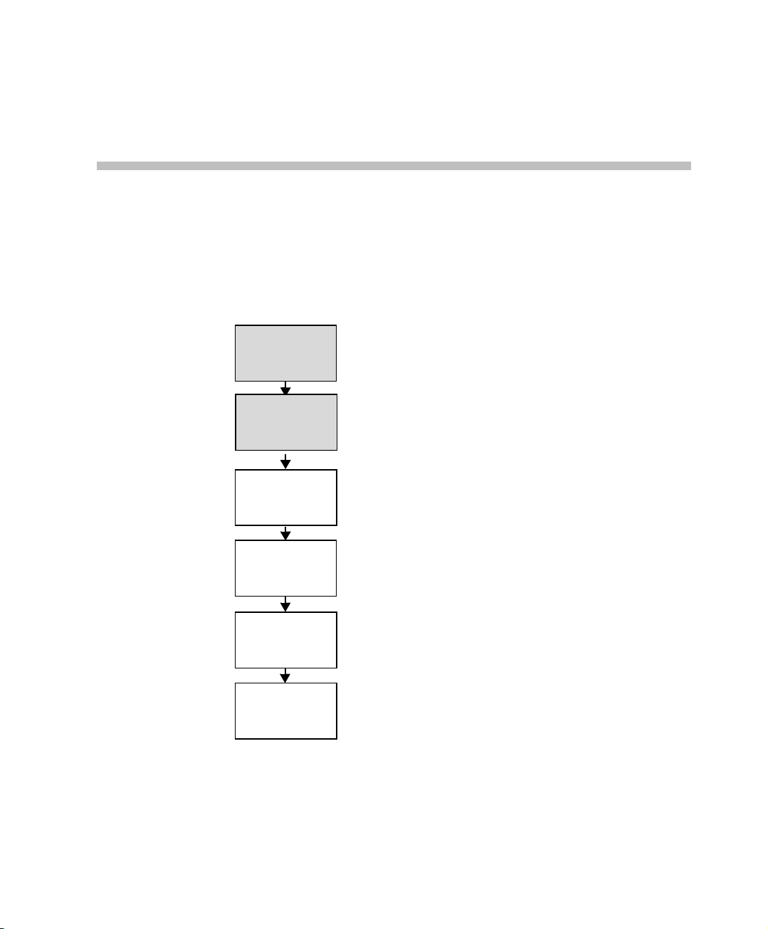
Hardware
Installation
First Entry MCU
IP Configuration
MGC Manager
Software
Installation
MGC Unit
Definition in the
MGC Manager
Network Services
Definition
Database
Configuration
MGC+ Getting Started Guide, Chapter 2
MGC+ Getting Started Guide, Chapter 2
MGC+ Getting Started Guide, Chapter 3
MGC+ Getting Started Guide, Chapter 3
MGC+ Getting Started Guide, Chapter 3
MGC+ User’s Guide - Volume II,
Chapter 6
Figure 2-1: Installation and Configuration Workflow - Hardware Installation
2-1
Page 14

Chapter 2 - Hardware Installation
MGC+100 Hardware Installation
Inspecting the MGC+/ReadiManager IAM Package Contents
You should inspect the shipped box and note if it was damaged in any way. If
the box items show damage, you should file a damage claim with the carrier
who delivered it.
When deciding on a setup location for the MGC+, refer to the section
“System Safety” on page 2-2.
Disclaimer
Polycom is not responsible for damage sustained during shipment of this
product.
System Safety
This section includes the foll ow topics related to system safety:
• “General Safety Precautions” on page 2-2
• “Rack Mount Safety Precautions” on page 2-3
• “Polycom MGC+/ReadiManager Precautions” on page 2-3
General Safety Precautions
Follow these rules to ensure general safety:
• Keep the area around the Polycom ReadiConvene clean and free of
clutter.
• The MGC+50 weighs approximately 24 kg (53 lbs) and the MGC+100
weighs approximately 48 kg (106 lbs). When lifting the system, two
people at either end should lift slowly with their feet spread out to
distribute the weight. Always keep your back straight and lift with your
legs.
2-2
Page 15

Rack Mount Safety Precautions
The following precautions should be followed with regards to rack mount
safety:
• Decide on a suitable location for the equipment rack that will hold the
MGC+ unit. It should be situated in a clean, dust-free area that is well
ventilated. Avoid areas where heat, electrical noise and electromagnetic
fields are generated. You will also need it placed near a grounded power
outlet.
• Ensure that the leveling jacks on the bottom of the rack are fully
extended to the floor with the full weight of the rack resting on them.
• In a single rack installation, stabilizers should be attached to the rack.
• In multiple rack installations, the racks should be coupled together.
• Always make sure the rack is stable before extending a component from
the rack.
• You should extend only one component at a time - extending two or more
simultaneously may cause the rack to become unstable.
• Before you install the rails, determine the placement of each component
in the rack.
• Install the heaviest server compone nts on the bottom of the rack firs t, and
then work up.
• Allow the power supply units to cool before touching them.
• Always keep the rack’s front door and all the blade’s panels and
components closed when not servicing, to maintain proper cooling.
MGC+50/MGC+100 Getting Started Guide
Polycom MGC+/ReadiManager Precautions
The following precautions should be followed with regards to installation of
the ReadiConvene:
Use a regulating uninterruptable power supply (UPS) to protect the MGC+
from power surges and voltage spikes, to keep your MCU and Readi Manag er
IAM operating in case of a power failure.
2-3
Page 16
Chapter 2 - Hardware Installation
C
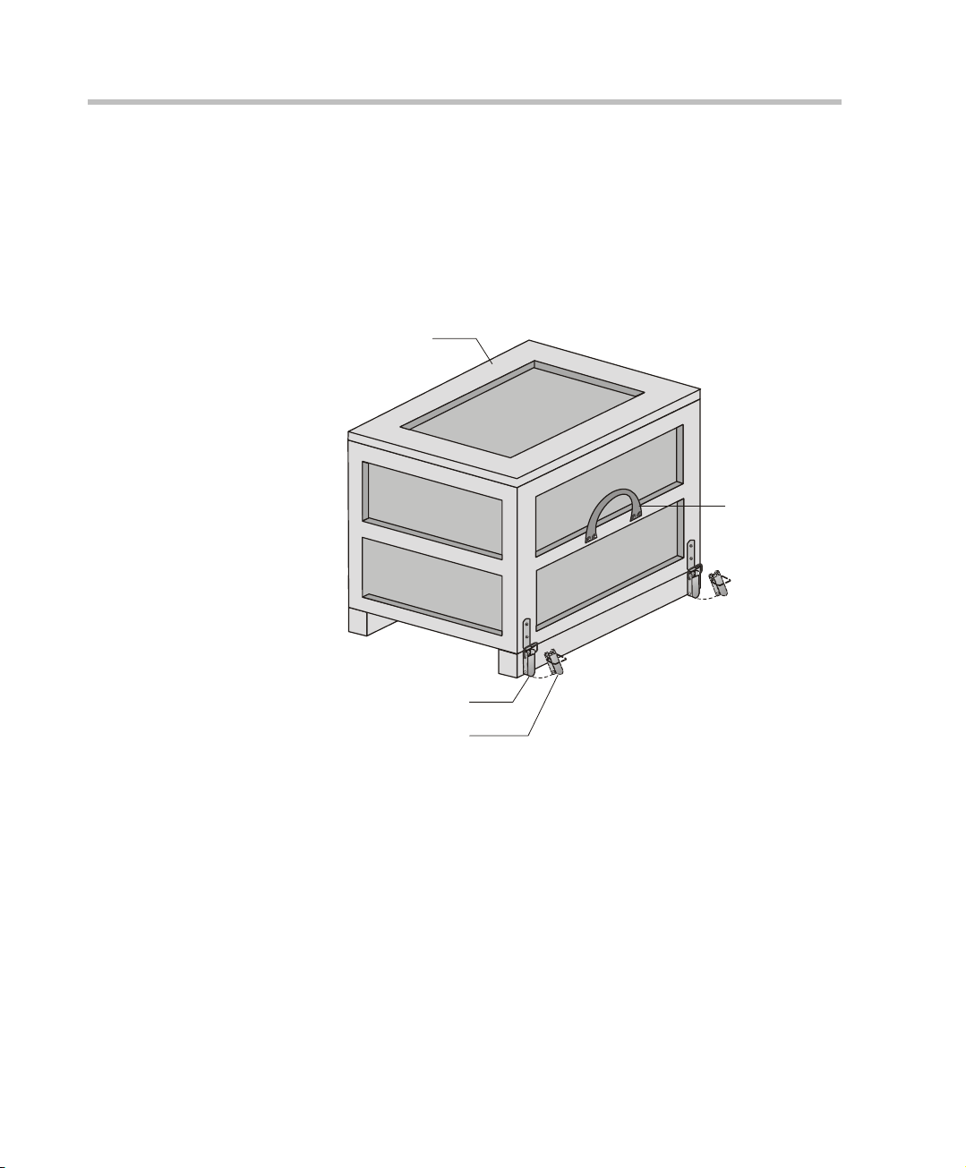
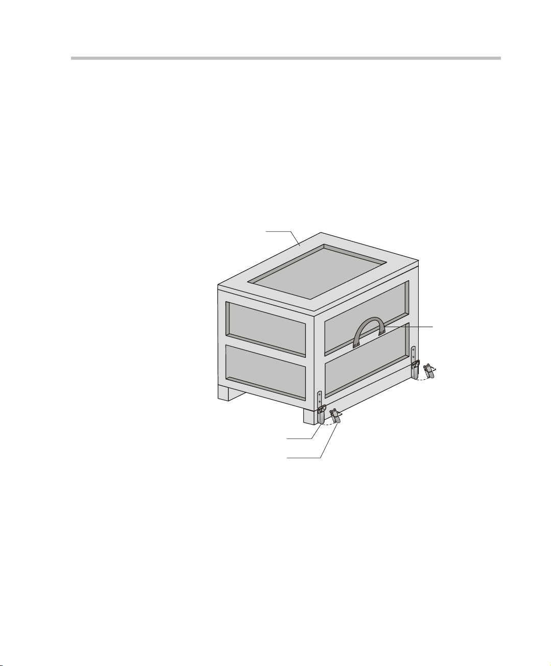
Unpacking and Positioning the MGC+100
To unpack and position the MGC+100:
1. When you receive your MGC+100, inspect the equipment for damage
and verify that the components match the packing slip. If you did not
receive a component or if there is damage to the system, notify your
service representative immediately.
Wood Packing
Lock in Closed Position
Lock in Open Position
Figure 2-1: MGC+100 package
ase
Carrying Strap
2. Place the MGC+100 unit on a stable flat surface in a location that meets
the MGC+ environment requirements, which are:
2-4
— Operating temperature: 10°–40°C (50°–104°F) or 10°–35°C
(50°–95°F) when installed in a 19” rack
— Humidity: 15%–90% non-condensing
— Altitude: Up to 3,000m (10,000ft)
— ESD: +8 kV
Page 17
MGC+50/MGC+100 Getting Started Guide
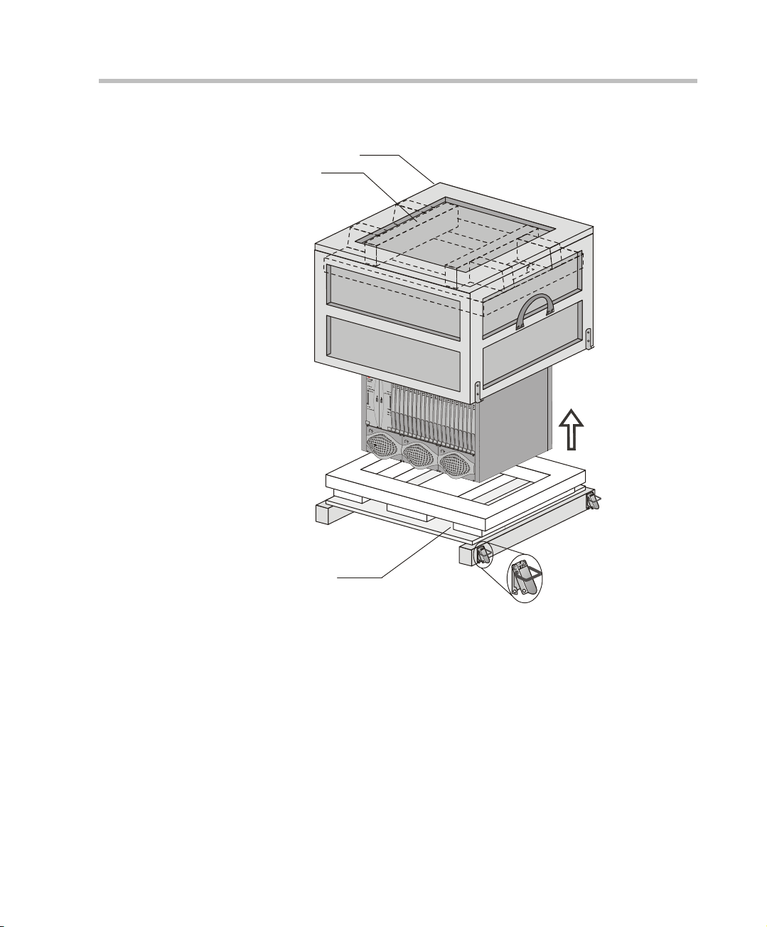
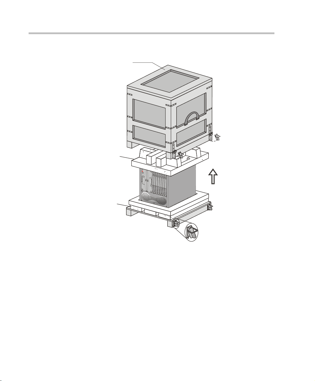
C
3. Release the clasp locks at the bottom, and lift the MGC+100 top cover.
Wood Packing
Foam Block
ase
Foam Block
Figure 2-2: Unpacking the MGC+100
4. Lift the MGC+100 unit and remove the packaging material.
5. Lower the MGC+100 unit, placing it on the surface.
If the MGC+100 is a standalone unit, place it on a flat surface. If you are
rack mounting the MGC+100, allow a minimum clearance of 3” above
the unit.
2-5
Page 18

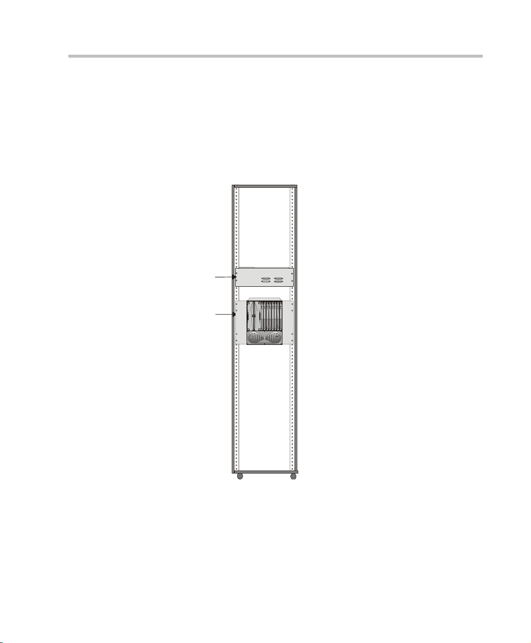
Chapter 2 - Hardware Installation
Mounting the MGC+100 in a 23” Rack
The MGC+100 can be mounted in a 23” rack using the two mounting plates
that are pre-installed on the unit.
1. Make sure that the MCU is turned OFF and it is disconnected from the
AC power.
2. Place the MCU in a 23” rack and support i t, screw the mounting brackets
to the rack securing it with bolts and
self-locking nuts (which the client provides).
When the unit is installed on a rack, the rack must be properly grounded to the
central office ground. The rack must be grounded with two-hole compressiontype connectors using copper conductors (tinned or untinned). Wire, bus bar or
braided strap connectors are acceptable.
If the MGC+100 was shipped without the two mounting plates that are
usually pre-installe d, refer to the MGC+ Hardware and Installation Manual,
Chapter 2 for a detailed description of the installation process.
For a detailed description of mounting the MGC+100 in a 19” rack, see the
MGC+ Hardw are and Installation Manual, Chapter 2 .
2-6
Page 19
MGC+50 Hardware Installation
C
Unpacking and Positioning the MGC+50
To unpack and position the MGC+50:
1. When you receive your MGC+50, inspect the equipment for damage and
verify that the components match the packing slip. If you did not receive
a component or if there is damage to the system, notify Polycom
immediately.
MGC+50/MGC+100 Getting Started Guide
Wood Packing
Lock in Closed Position
Lock in Open Position
Figure 2-3: MGC+50 package
ase
Carrying Strap
2. Place the MGC+50 unit on a stable flat surface in a location that meets
the MGC+50’s environment requirements, which are:
— Operating temperature: 10°–40°C (50°–104°F)
— Humidity: 15%–90% noncondensing
— Altitude: Up to 3,000m (10,000ft)
— ESD: +8 kV
2-7
Page 20
Chapter 2 - Hardware Installation
C
3. Release the clasp locks at the bottom, and lift the MGC+50 top cover.
Wood Packing
Foam Block
Foam Block
ase
2-8
Figure 2-4: Unpacking the MGC+50
4. Lift the MGC+50 unit and remove the package base.
5. Lower the MGC+50 unit, placing it on the surface.
If you are rack mounting the MGC+50, allow a minimum clearance of 3
inches above the unit.
Page 21
Mounting the MGC+50 on a Rack
The MGC+50 can be mounted in a 19” rack using the two mounting plates
that are usually pre-installed.
To install and mount the MGC+50:
• Place the MGC+50 in a 19” rack and while supporting it, screw the
mounting brackets to the rack securing it with nuts.
MPI Box
R
POLYCOM
MGC+
Power
Power
Flash Memory
Flash Memory
Mounting
Plate
Shut Down
Reset
HD
Major
Remove Server
Minor
Power
Out
MGC+50/MGC+100 Getting Started Guide
Line 1
Line 2
Line 3
Line 4
Line 5
Line 6
Line 1
Line 7
Line 8
Line 2
2-9
Page 22
Chapter 2 - Hardware Installation
Connecting and Setting Up the MGC+100/ MGC+50
To Connect the MGC+100/ MGC+50 to the network and power source and
set up the system the following procedures are performed:
• Connecting the MGC+ uni t to the power source (AC inlet)
• Connecting the MGC+ unit to the LAN Network
• Connecting the MGC+ unit to the network(s)
Connecting to the Power Source
You can connect to an AC Inlet power supply at your site. It is important to
follow these steps.
The following restrictio ns apply to the c onducto rs and connectors t hat may be
used to ground the unit when rack mounted:
• When using bare conductors, they must be coated with an appropriate
antioxidant compound before crimp connections are made. Tinned,
solder-plated or silver-plated connectors do not have to be prepared in
this manner.
• The same bolt assemblies should not secure multiple connectors.
• Listed fastening hardware must be compatible with the materials being
joined and must be preclude l oosening, deteri oration and e lectrochemical
corrosion of the hardware and joint materials.
2-10
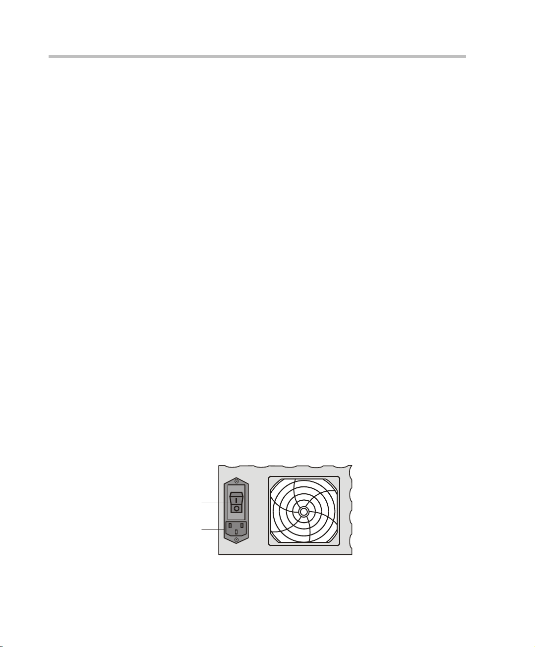
To connect to the AC Inlet:
1. Make sure the power switch is OFF. Insert the power cable into the
power connector on the rear panel of the MGC+100 unit.
Main Switch
AC Inlet
2. Insert the power cable into the power source socket.
Page 23
MGC+50/MGC+100 Getting Started Guide
3. Turn on the power by pressing on the power switch located on the rear
panel of the MGC+100/ MGC+50 unit.
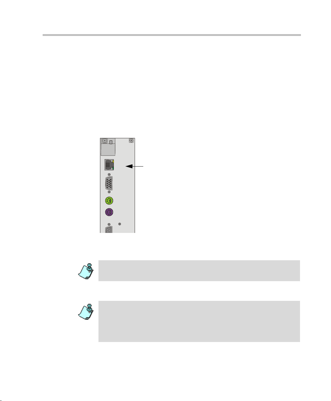
Connecting the MGC+100/MGC+50 to the Local Network
The MGC+ must be connected to the local LAN network to enable
communication between the MGC+ unit and the PC workstations running the
MGC Manager application.
Connect one end of a network cable to the LAN connector on the rear I/O
panel of the MGC+ Control Module and the other end to the network.
LAN
VGA
MOUSE
KEYBOARD
Connecting the MGC+ to the Conferencing Network
The installati on of th e M PI box on the MGC+ unit and the c onn ec tion to the MPI
Network module are described in the MGC+ Hardware and Installation Manual,
Chapter 2.
Connecting the MGC+ to the ISDN/ T1-CAS Network
The ISDN network is optional. If the MGC+ has to be connected to the public
ISDN network then an external CSU or similar equipment is needed.
T1-CAS network is optional. It allows you to connect Audio Only participants to
conferences via T1-CAS lines. It uses the same network connections as ISDN
and the procedure described below is applicable to both ISDN and T1-CAS
lines.
2-11
Page 24
Chapter 2 - Hardware Installation
p
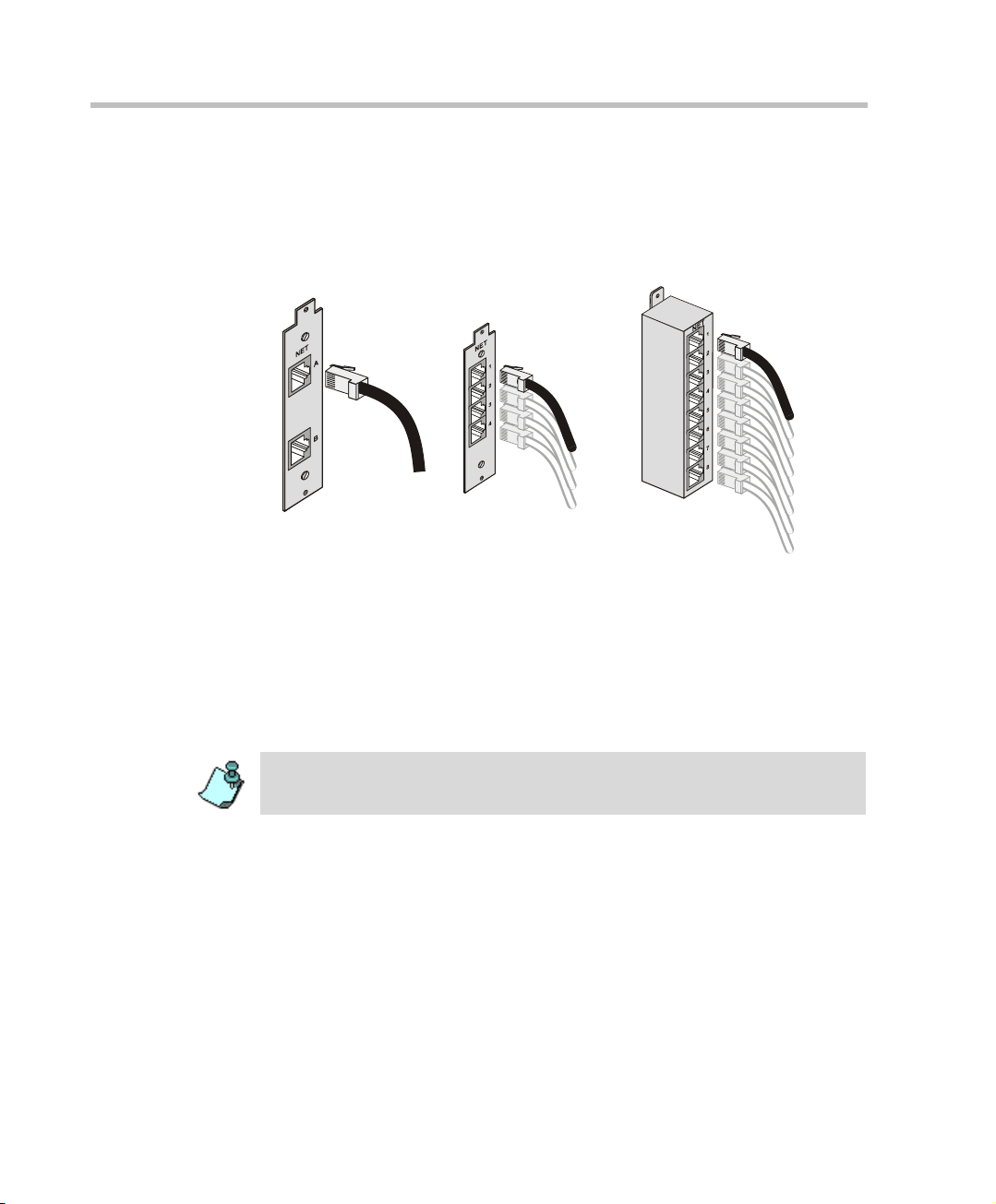
To connect the MGC+ to the ISDN network or T1-CAS Network:
• Connect the 8-pin RJ-45 connector of the network cable to the NET
RJ-45 jack on the rear panel of the MGC+. Repeat this step for each of
the ISDN network lines to be connected to the Network Interface card
installed in the MCU.
ISDN network
connection
ISDN Network connection
for 4 spans
ISDN Network connection
for 8 s
ans
Figure 2-5: ISDN network conne ction
Leased lines should be connected using an adapter with a screw
connector with solid conductor wires or a similar adapter.
• Connect one side of the adapter to the NET RJ-45 jack on the rear panel
of the MGC+. Then connect the leased line wires to the other side of the
adapter.
The ISDN and T1-CAS network properties must be defined in the Network
Services. For details, see the MGC+ Administrator’s Guide, Chapter 3.
2-12
Page 25
MGC+50/MGC+100 Getting Started Guide
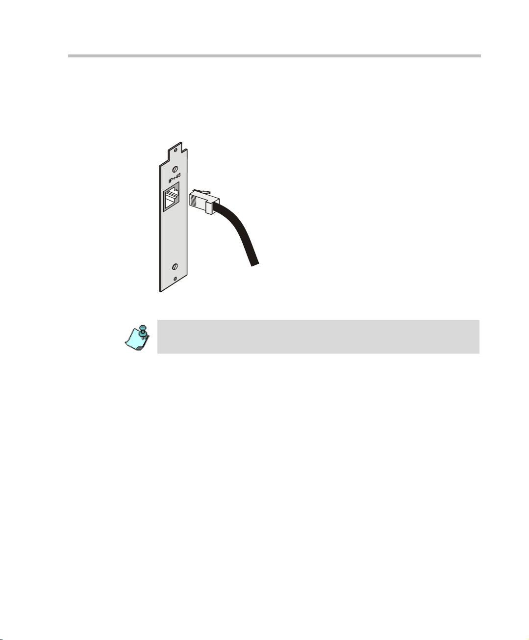
Connecting the MGC+ to the IP Network
If an IP network Interface card is installed in the MGC+, connect the 8-pin
RJ-45 connector of the LAN networ k cable to the LAN-32 3 RJ-45 jac k on the
rear panel of the MGC+.
Figure 2-6: LAN IP network connection
The IP network properti es mu st be defined in the Network Servic es , Fo r de t ail s,
see MGC+ Administrator’s Guide, Chapter 3.
2-13
Page 26
Chapter 2 - Hardware Installation
First Entry MGC+ Control Unit (CU) IP Configuration
The MCU is delivered with a default IP address: 129.254.4.8. At this point
you cannot communicate with the MCU f rom th e MGC Manager ap plica tion,
as the IP address is incorrect. You must change this IP address to the IP
address appropriate for your site’s network. There are three methods to
modify the default IP address:
• Using the Compact Flash with an updated LAN.CFG file
• Using a cross-over hub cable and a laptop to connect to the MCU locally
• Using a keyboard and monitor attached to the MCU
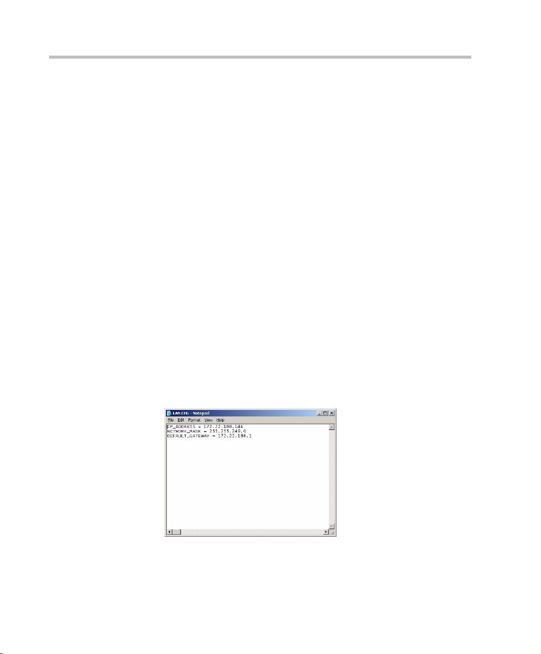
Using the Compact Flash Disk with the LAN.CFG File
The MCU is delivered with a Compact Flash disk t hat contains a LAN.cfg file
with the default IP address. Using a USB to Compact F lash ada ptor (suppl i ed
with the MGC+ accessory kit) connect to any PC and alter the LAN.cfg file.
To update the LAN.cfg File:
1. Insert the Compact Flash disk into the Compact Flash adaptor and using
a text editor application, open the LAN.cfg file stored on the Compact
Flash disk.
2-14
2. Using a text editor application, edit the following parameters:
:
Page 27
MGC+50/MGC+100 Getting Started Guide
Table 2-1: IP Configurati on Options
Option Description
IP Address The system displays the currently defined IP address.
Enter the IP address allocated to the MCU by the
network administrator.
Subnet Mask Enter the Subnet Mask of the MCU.
Default Gateway Enter the IP Address of the default gateway/router.
Make sure no blank spaces occur at the end of each line.
3. Save the changes in the LAN.cfg file.
4. Use the Microsoft Unplug or Eject Hardware procedure prior to
removing the Flash disk.
Failure to stop the hardware properly can result in a corrupt Compact Flash disk.
When the disk fails, a replacement is required.
5. Remove the Compact Flash disk from the reader.
6. Insert the Compact Flash disk into the Compact Flash slot of the MGC+
Control Module.
7. Press the Reset button on the MGC+ unit.
The Options menu appears.
8. Press 1, to Change the MGC+ IP Settings.
If no monitor is connected, the automatic default time-out (15 seconds) selects
option 1.
The Flash Memory LED must be active and flash.
2-15
Page 28

Chapter 2 - Hardware Installation
9. Press the Eject button.
Once the message “1 File(s) copied” is displayed on screen, the
Flash Memory LED no longer flashes.
Do not press the Eject button while the Flash Memory LED is flashing.
10. Remove the Compact Flash disk from the Compact Flash slot on the
MGC+ Control Module and press the Reset button on the MGC+.
11. Connect the MCU to your site’s networ k.
12. Install the MGC Manager and start this application. For more
information, see Chapter 3, “Starting the MGC Manager Application”
on page 3-4.
13. In the MGC Manager, define a new MCU using the IP address you have
entered in the LAN.CFG file. For more information, see Chapter 3,
“Defining the MCU” on page 3-5.
Using a Cross-over Hub Cable and a Laptop to Connect to the MCU Locally
2-16
1. Connect a cross-over hub cable between the laptop LAN connection to
the LAN connection of the control unit on the rear panel of the MCU.
2. On the laptop Start menu, click Control Panel ->Network Connection>Local Area Connection.
3. In the Local Ar ea Con necti on - General di alog bo x
button
.
4. In the Local Area Connection Properties dialog box, click Use the
following IP address, and define the address of the laptop as part of the
same network segment as the MCU. For example, 129.254.4.7.
5. Click OK.
6. Install the MGC Manager and start this application. For more
information, see Chapter 3, “Starting the MGC Manager Application”
on page 3-4.
7. Define the MCU using the default IP address (129.254.4.8). For more
information, see Chapter 3, “Defining the MCU” on page 3-5.
, click the Properties
Page 29
MGC+50/MGC+100 Getting Started Guide
8. In the MCUs list, double-click the MCU icon to connect to it.
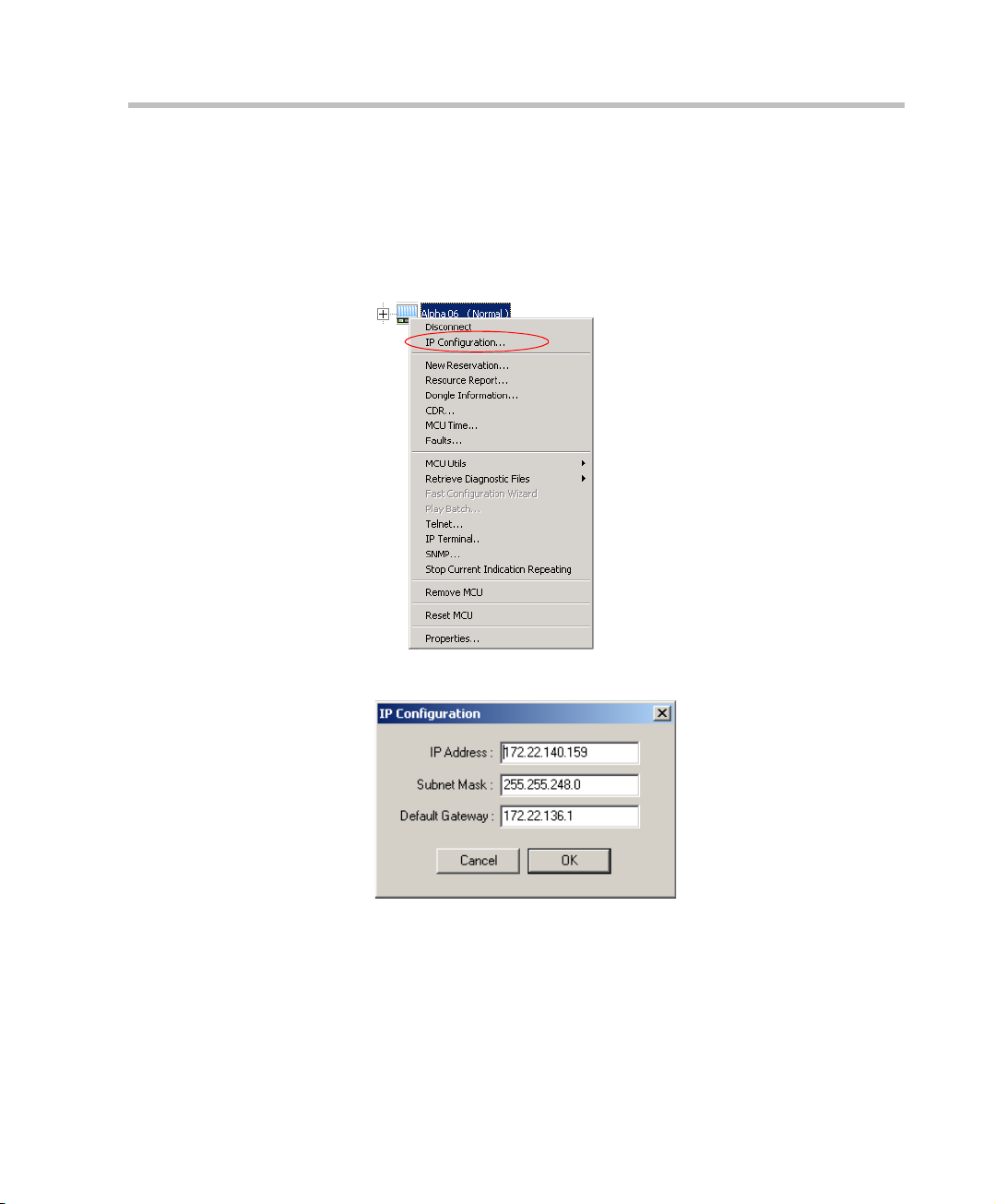
9. Modify the IP address of the MCU unit as allocated by the network
administrator. This is the IP address with which the MCU is identified on
the LAN and not its definition in the MGC Manager application:
a. Right-click th e MCU icon, and then click IP Configuration.
The IP Configuration dialog box opens.
b. The following parameters may be modified:
c. Click OK.
10. Press the Reset button on the MGC+ unit.
11. Disconnect the MCU from the local network that you have created.
12. Connect the MCU to your site’s network.
2-17
Page 30
Chapter 2 - Hardware Installation
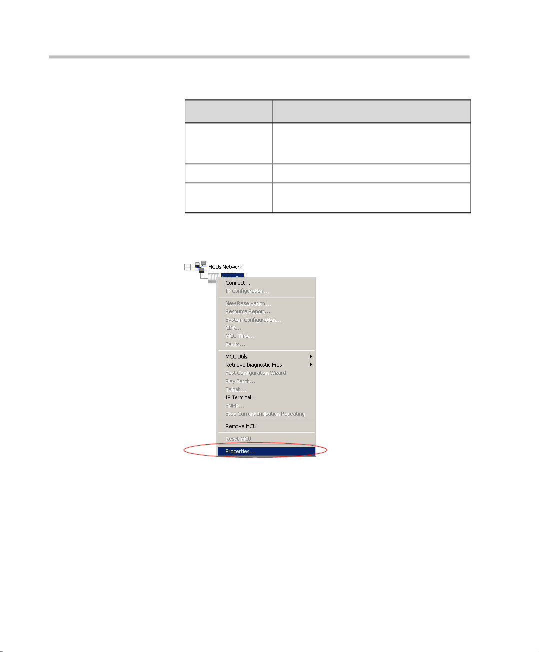
13. In the MGC Manager application, modify the MCU definition:
a. Right-click the MCU icon, and then click Properties.
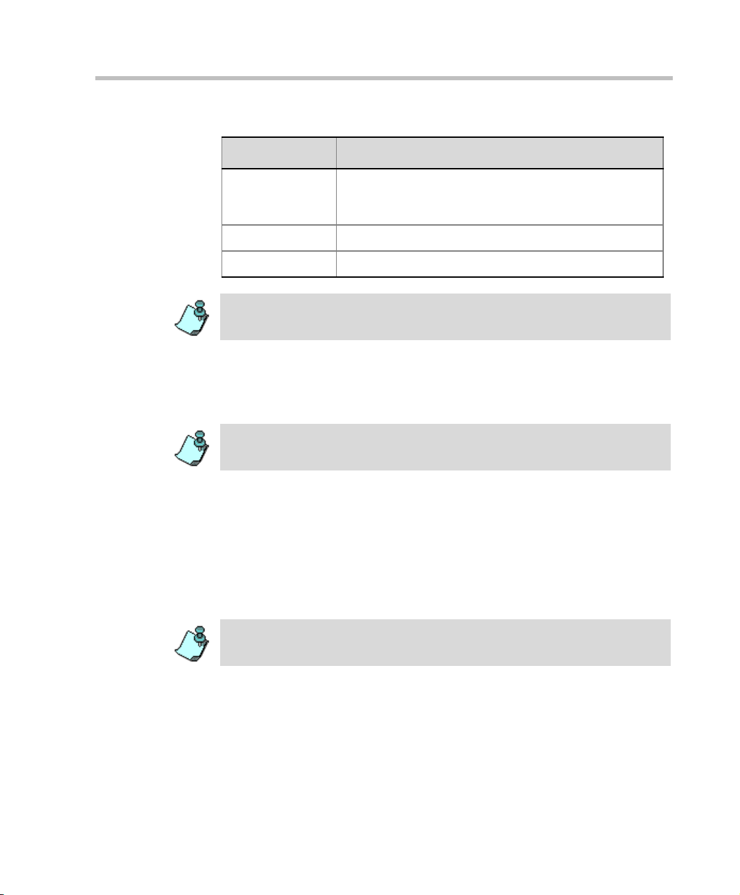
Table 2-2: IP Configuration Options
Option Description
IP Address The system displays the currently defined IP
address. Enter the IP address allocated to the
MCU by the network administrator.
Subnet Mask Enter the Subnet Mask of the MCU.
Default Gateway Enter the IP Address of the default gateway/
router.
2-18
Page 31

MGC+50/MGC+100 Getting Started Guide
The MCU Properties dialog box opens.
The current MCU name.
To modify, type a new
name
MCU IP address. Enter
the IP address of the MCU
as allocated by the
network administrator
b. Enter the IP address of the MCU as you have defined in the IP
Configuration.
c. Click OK.
14. Connect to the MCU.
Using a Keyboard and Monitor Attached to the MGC+ unit
1. Access the Main Control Module rear I/O panel and connect the
keyboard and the monitor to the appropriate ports.
2-19
Page 32

Chapter 2 - Hardware Installation
2. Press the Reset button on the MCU.
The comma nd line is displayed on the monitor.
3. Type C:\>dir mcu\cfg and press Enter.
4. Type C:\>\mcu\cfg>edit lan.cfg and press Enter.
The Edit screen opens displaying the IP configuration parameters.
5. Move the cursor to the appropriate line and enter the new IP Addr ess, as
supplied by the network administrator.
If required, modify the Subnet Mask and the Default Gateway values.
6. Save the new IP configuration and exit the DOS editor.
7. Press the Reset button on the MCU.
8. Connect the MCU to your local network.
9. Install the MGC Manager application and start this applicat ion. For more
information, see Chapter 3, “Installing the MGC Manager” on page 3-2.
10. Define a new MCU using the address entered via the monitor and
keyboard. For more information, see Chapter 3, “Defining the MCU” on
page 3-5.
The new MCU is added to the MCUs list.
2-20
Another method to connect to the MCU and modify its IP configuration is via a
telephone line with a modem or directly via a serial connection. For details, see
the MGC+ Administrator’s Guide, Appendix C, “PPP Setup”.
Page 33

MGC+ Sof tware Installation and Configuration
The MGC+50/MGC+100 requires basic configuration before you can start
running conferences. You are required to configure the ReadiManager IAM
and MGC+ Control Unit (CU) blades on the MGC+.
Initial ReadiManager IAM Configuration
For entering system config uration settings an d deployi ng the ReadiM anager
IAM to your Network refer to the Polycom ReadiManager IAM Getting
Started Guide, Chapters 1 and 2.
3
3-1
Page 34

MGC+50/MGC+100 Getting Started Guide
Installing the MGC Manager
To configure the MGC+ unit to your environment, setup conferences and
Initial IP
Configuration
Installing the
MGC Manager
Start ing the MGC
Manager
control the MGC+ uni t yo u must install the MGC Manager softwar e o n a PC.
A single MGC Manager-enabled PC can manage multiple MCUs.
During the installation, default Reservat ion templates are installed.The MGC
unit is shipped with a Default IVR Service and Default Entry Queue Service.
For information about restoring these services when upgrading MCU
software, refer to the MGC Administrator’s Guide, Chapter 5.
To install the MGC Manager software:
1. Insert the software CD into the CD drive.
2. On the Start menu, click Run.
The Run dialog box opens.
Defining an MCU
Connecting
to an MCU
Configuring the
Network Services
3. Type D:\SETUP (where D is the name of the CD drive), and then click
OK.
The installation wizard starts and the Software License Agreement
window opens.
4. Click Yes to accept to the terms of the agreement or No to exit the
installation.
If you clicked Yes, the Welcome window opens.
5. Click Next.
3-2
Page 35

Chapter 3 - MGC+ Softwa r e I ns tallation and Configuration
The User Information screen opens.
6. Enter your name and the name of your company in the appropriate
boxes. For a standard installation, enter Polycom in the Serial box.
7. Click Next.
8. Follow the on-screen instructions to complete the installation process.
At the end of the installation procedure, the Setup Complete window
opens.
9. Click Finish.
The MGC Manager software is now installed on your computer.
3-3
Page 36

MGC+50/MGC+100 Getting Started Guide
Starting the MGC Manager Application
The MGC Manager application is designed to set up and m onitor multipoint
Initial IP
Configuration
Installing the
MGC Manager
Start ing the MGC
Manager
Defining an MCU
Connecting
to an MCU
video conferences, and to perform system configuration activities for the
MGC+ Multipoint Control Units (MCUs) to which it connects.
To start the MGC Manager application:
• On the Start - Programs menu, select MGC Manager ver 9.0, and then
click MGC Manager ver 9.0.
The MGC Manager main window opens
Configuring the
Network Services
3-4
Main Menu
Toolbars
Status pane
Browser
Monitor pane
Page 37

Defining the MCU
T o manage and control the M GC+ unit i t must be added t o the MCUs network
Initial IP
Configuration
Installing the
MGC Manager
Starti ng the MGC
Manager
list in the MGC Manager application.
The MGC unit has to be installed and its IP address properly
configured before defining its connection parameters in the MGC
Manager application. For details, see Chapter 2, “First Entry MGC+
Control Unit (CU) IP Configuration” on page 2-18.
To define an MCU Connection:
1. In the Browser pane, right-click the MCUs Network icon, and then click
New MCU.
Chapter 3 - MGC+ Softwa r e I ns tallation and Configuration
Defining an MCU
Connecting
to an MCU
Configuring the
Network Services
The Add MCU dialog box opens.
2. In the Name box, e nter the name of the MCU. Specify a name that clearly
identifies the MCU.
3. In the IP Address box, enter the IP Address of the MCU.
The IP address should be identical to the one configured during the Initial IP
Configuration.
3-5
Page 38

MGC+50/MGC+100 Getting Started Guide
4. Click OK.
The Add MCU dialog box closes.
A new icon with the specified MCU name appears in the Browser pane
listed below the MCUs Network icon.
3-6
Page 39

Connecting to an MCU
Chapter 3 - MGC+ Softwa r e I ns tallation and Configuration
Initial IP
Configuration
Installing the
MGC Manager
Start ing the MGC
Manager
Defining an MCU
Connecting
to an MCU
Configuring the
Network Services
Once the MCU connection parameters are defined, the MGC Manager can
connected to it. The MGC Manager reports the status of each MCU
connection.
To connect the operator workstation to an MCU:
1. In the Browser pane, dou ble-click the MCUs Network icon, or expand t he
MCUs Network icon.
A list of MCUs appears below the MCUs Network icon.
2. Double-clic k the MCU icon.
Alternatively, right click the MCU icon to which you want to connect,
and then click Connect.
The Logon dialog box opens.
3. Enter your Login Name and Password, and then click OK.
Note that each MCU is initially configured with a default operat or whose
Login and Password are both POLYCOM. Additional operators can be
defined. For more details, see the MGC Administrator’s Guide,
Chapter 6.
3-7
Page 40

MGC+50/MGC+100 Getting Started Guide
Configuring the Network Services
The Network Services include the parameters of the networks connected to
Initial IP
Configuration
the MCU. If no Network Services have been configured, depending on your
system configuration, the appropriate Network Service must be configured.
This section describes the configuration of both IP and ISDN networks.
Installing the
MGC Manager
Starti ng the MGC
Manager
Defining an MCU
Connecting
to an MCU
Configuring the
Network Services
For information about defi ning T1 -CAS, MPI, N FAS ISDN, Leased lines
ISDN and additional ISDN and IP Network Services, or modifying
existing Network Services, refer to the MGC Administrator’s Guide,
Chapter 3.
ISDN Network Service
The Net-2/4/8 card installed in the MCU interfaces between the MGC unit
and the ISDN switch. The ISDN Network Service is used to define the
properties of the switch and the ISDN lines running from the switch to the
ISDN card. Each group of ISDN lines having the same characteristics and
originating from the same ISDN switch, will be assigned to the same ISDN
Network Service.
IP Network Service
The IP Network Service defines the properties of the IP netwo rk connected t o
the IP+ cards (installed in the MCU). Several of the network compon ents are
used by both H.323 and SIP endpoints to connect to the conference, and the
same IP+ card is used for H.323 and SIP connections. One IP Network
Service, therefore, can be defined for both H.323 and SIP environments as
well as an H.323-only or a SIP-only Network Service.
Defining the Network Services
The first time you connect to the MGC+ unit from the MGC Manager, the
system automatically detects that no Network Service is defined in your
system and automatically displays the Network Configuration Wizard to let
you configure the IP and ISDN Network Services.
If the system detect an ISDN only connection to the MCU, only the ISDN
Configuration dialog b ox opens. If an IP-onl y connect ion is de tected, on ly the
IP Configuration dialog box opens.
3-8
You can always access the Fast Configuration Wizard by right-clicking the MCU
icon.
Page 41

Chapter 3 - MGC+ Softwa r e I ns tallation and Configuration
To define the Network Service:
1. In the Network Conf iguration Wizard window, click either IP or ISDN.
The the configuration process can start in any order.
If you have selected IP, the IP Configuration dialog box opens.
3-9
Page 42

MGC+50/MGC+100 Getting Started Guide
2. Define the following parameters:
To route Meet Me H.323 dial-in participants to their conferences using a IP
Network Service prefix as part o f the dia ling strin g, some gatekeep ers require th e
configuration of an IP Network Service prefix prior to its definition in the
gatekeeper. With Polycom PathNavigator, the IP Network Service prefix
automatically registers with the gatekeeper and does not require prior definition.
Table 3-1: IP Configuration Parameters
Field Description
IP Service
Name
Obtain IP
Address
automatically
(DHCP)
All Spans
Configuration
Enter a name using up to 20 characters, or use the
default name (IP Default Service).
Select this check box to use a DHCP server for
automatic assignment and tracking of IP addresses to
the conference devices.
Do not select this check box if you need to:
• Establish a static IP address, for example, when
working with a firewall and you need to translate an
internal IP address, that must be static, with an
external one.
• When dialing in directly to the card, using the card’s
IP address.
Select this check box to indicate that a LAN span is
connected to the IP+ card in the MCU and to define the
properties of this card.
3-10
Page 43

Chapter 3 - MGC+ Softwa r e I ns tallation and Configuration
Table 3-1: IP Configuration Parameters (Continued)
Field Description
Cards
Configuration
Click this button to automatically detect the IP address
and Alias (if known) of the IP+ cards installed on the
MCU.
The IP+ card type and its slot number, IP address and
alias are listed. When the Obtain IP Address
automatically (DHCP) check box is selected, the IP
address of the card appears as 0.0.0.0.
To configure a specific IP+ card:
Highlighting and then double clicking on any card.
Enter or change the IP address, and add the card’s
Alias if required and click OK.
Subnet Mask Enter the subnet mask of the MCU’s IP+ card. If the
DHCP is used, the subnet mask is automatically
retrieved from the DHCP server and cannot be
modified. For more det a ils, see the M GC Adm inist rators
Guide, Chapter 3, “Defining an IP Network Service”.
3-11
Page 44

MGC+50/MGC+100 Getting Started Guide
Table 3-1: IP Configuration Parameters (Continued)
Field Description
Default Router Enter the IP address of the default router. If a DHCP is
DNS Select this check box to indicate that a DNS server is
used, the IP address of the default router is
automatically retrieved from the DHCP server and
cannot be modified.
used in the network. Then select:
• Specify - Select this option to enter the IP address
of the DNS server.
• Auto - select this option to automatically detect the
primary DNS IP address, provided the DNS Server
is defined in the DHCP and if the DHCP -obtain IP
Address automatically check box was selected.
DNS Server IP
Address
Local Domain
Name
H.323 Select this option to allow H.323 participants to connect
Gatekeeper If a gatekeeper is used, select the Gatekeeper check
Gatekeeper IP
Address or
Name
If Specify was selected, enter the IP address of the
primary D NS server to be used.
Enter the domain name where the MCU is installed.
The name of the domain includes the host part of URL
or URI (the part of the host’s address that appears after
the at sign (@), or in a URL the part following the www.
prefix), for example, polycom.com.
This field is used both for SIP proxy registration
purposes and DNS resolution and therefore it is
required if you are using DNS servers in this service.
to the MCU using this service.
box to define its properties.
Enter either the gatekeeper’s host name (if the DNS
server is us ed), or IP address.
3-12
Page 45

Chapter 3 - MGC+ Softwa r e I ns tallation and Configuration
Table 3-1: IP Configuration Parameters (Continued)
Field Description
Prefix Enter a number to be used by H.323 participants to dial
to the MCU as part of the dial-in string.
789 to use the default Entry Queues and Meeting
Enter
Rooms shipped with the MGC+ unit without modifying
their properties.
When PathNavigator is used, this prefix automatically
registers with the gatekeeper. When another
gatekeeper is used, this prefix must also be defined in
the gatekeeper.
SIP Select this check box to indicate that SIP participants
can connect to the MCU using this service. Then select:
• Specify - to manually define the SIP server.
• Auto - to automatically detect the SIP server’s IP
address if a DHCP or if a DNS Server is defined.
SIP Server IP
Address or
Name
Domain Name
or IP Address
If SIP-Specify is selected, and a DHCP is not used,
enter either the IP address of the preferred SIP server
or its host name (if a DNS server is used).
Conferences and En try Q ueues can be regist ered i n the
proxy in the format user@host. for example,
EQ1@polycom.com, where EQ1is the user part and
polycom.com is the host part.
When dialing to a conference or Entry Queue, the SIP
server expects to receive the host either as domain
name or as an IP address.
The domain name is used for identifying the SIP server
in the appropriate domain according to the host part in
the dialed string. For example, when the call to
EQ1@polycom.com reaches the outbound proxy, this
proxy looks for the SIP server in the polycom.com
domain to which it will forward the call.
When this call arriv es at the SIP ser ver in poly com.c om,
the server looks for the registered user (EQ1) and
forwards the call to this Entry Queue or conference.
3-13
Page 46

MGC+50/MGC+100 Getting Started Guide
3. Click OK.
If your system supports only IP networks, a confirmation message is
displayed.
4. Click OK.
If you are defining only th e IP Networ k Service, th e Netwo rk Con figurati on dial og
box closes and the new IP Network Service appears in the IP Network Services
list.
If you are defining both IP and ISDN Network Services, the Network
Configuration Wizard dialog box is displayed.
To configure an ISDN Network Service:
5. Click the ISDN button.
The ISDN Configuration dialog box opens.
3-14
6. In the ISDN Service Name box, enter a name or use the default name
(ISDN Default Service) .
Page 47

Chapter 3 - MGC+ Softwa r e I ns tallation and Configuration
7. Click PRI Configuration to define any ISDN span.
The ISDN Cards configuration window appears.
ISDN (Net) cards present on the MCU are automatically listed together
with their slot numbe r.
a. Select any PRI span by selecting the relevant check box.
b. Click OK when complete.
8. In the Line Type list, select either T1 (usually in the U.S., T1 has 23 B
channels + 1 D channel), or E1 (usuall y in Euro pe, E1 has 30 B channels
+ 1 D channel).
9. In the Switch Type list, select the brand and revision level of equipment
installed in the telephone company’s central office.
10. In the Dial-In Numbers Range boxes, enter the phone numbers to be used
for dial-in connection s as allocated to th e MCU by your service pr ovider.
Enter the first and last numbers in the range of phone numbers.
11. Click OK.
A confirmation message is displayed.
12. Click OK.
For advanced settings, see the MGC Administrator’s Guide, C hap ter 3.
3-15
Page 48

MGC+50/MGC+100 Getting Started Guide
The Network Services definition is complete, and the Network Configuration
dialog box closes. The new Network Services appear in the IP Network
Services and the ISDN Network Services lists.
3-16
The following icons are used to indicate the IP Network Service type:
Table 3-2: IP Network Service Icons
Icon Description
The Network Service supports both SIP and H.323
connections.
The Network Service supports only H.323
connections.
The Network Service su ppo rt s on ly SIP c on nec tio ns .
By default, the new Network Services are set as the system default. When
defining additional Network Services for IP or ISDN connections these
defaults can be changed. For more details, see the MGC Administrator’s
Guide, Chapter 3.
Page 49

About Conferences
Different conference types are available according to their initiation modes:
reservationless conferences and scheduled conferences.
On-Demand (Reservation-le ss) Conferencing
Reservation-less conferencing enables participants to immediately start and
connect to an On Going Conference from their endpoint, with no advanced
scheduling. The MGC Manager offers two methods for Reservation-less
conferencing:
• Ad Hoc Conferencing
• Meeting Rooms
Ad Hoc Conferencing
In Ad Hoc conferencing, participants connect to an Ad Hoc-enabled Entry
Queue. An Entry Queue is a special routing lobby to which one or several
dial-in numbers are assigned. The participants are prompted for the
destination conference Numeric ID. If no conference with a matching
Numeric ID is running, but the participant is authorized to create a
conference, the system creates a new On Going Conference. The new
conference is created according to the conference parameters defined in a
Profile assigned to the Entry Queue. All other participants connect directly
to the newly created conference. With this method, only the conference
Profile is created once and is used repeatedly to create numerous
conferences.
This conferencing method is often used to globally enable all employees in
an organization to star t On Going Conf erences from thei r endpoints, wit hout
having to define the conference parameters for each employee and for each
conference.
When authentication with external database applicat ion is configured for the
Entry Queue and for the conference, the MCU verifies with the external
4
4-1
Page 50

MGC+50/MGC+100 Getting Started Guide
database application whether a conferen ce with a speci fic Numeric ID may be
started. This is the method used with Windows Messenger and Office
Communicator to initiate multipoint Video or Audio conferences.
For more information about Ad Hoc conferencing, see the MGC Manager
User’s Guide, Volume II, Chapter 3.
Meeting Rooms
Meeting Rooms are conferences created once, with no starting date or time,
no reserved resources and it can be activated as many times as required. The
Meeting Room remains in passive mode until the first parti ci pant conne cts t o
it and activates the conference. To start the conference you simply let the
participants know the start date and time, dial -in numb er and the Numeri c ID
of the conference. No prior booking is required. The conference returns to
passive mode once the conference ends and remains in the MCU memory
until the next activ ati on . In thi s mode, a Meeting Room is usually defined for
each of the employees in your organization. This may require tedious work
when your organization i ncludes many empl oyees, and i t also loads the MC U
memory with all the saved Meeting Rooms.
Scheduled Conferences
You can define a conference to start at a certain date and time or to start
immediately. Scheduled conferences run once and are then deleted from the
MCU memory. For scheduled conferences, the MCU reserves resources for
the conference participants, provided the participant endpoints are defined
during the conference definition. You can define conferences without
defining their participants and let participants connect to the conference as
long as there are resources available.
4-2
Page 51

Video Conference Attributes
There are four general types of video conferences:
• Video Switching - A conference in which all participants use the same
video and audio formats. Whenever a participant starts to speak, the
participant appears on all endpoints in full screen display as the
conference is a voice activated video switching conference.
• Transcoding (requires Video card) - A conference in which participants
use different video, audio and data formats, while maintaining the
highest video and audio capability each participant can achieve with his
or her codec. Like video switching, the current speaker is displayed on
all endpoints in full screen.
• Continuous Presence (requires Video card) - A conference in which
several participants can be viewed simultaneously. In this type of
conference, the highest video , audio and dat a qua lity for each partici pant
depends on the parti cipants endpoint capabilities.
In a traditional Continuous Presence conference, each participant uses a
different video port on the V ideo card. This method enabl es such features
as full Transcoding per participant, Personal Layouts (individualized
Continuous Presence layouts per par ticipan t) and main tenance of overall
video and audio quality for the conf erence—even when par ticip ants with
lower capabilities connect. However, this method limits the number of
Continuous Presence participants to the number of ports on the Video
card, which is six.
• Conference On Port (requires Video card) - A conferencing method
suitable for large Continuous Presence conferences or when several
Continuous Presence conferences are running on the MCU.
In Conference On Port, all conference participants use a single video
port. This method allows for more than six participants to join a
Continuous Presence conference and allows for up to six Continuous
Presence conferences to be run on the MCU.
In a Conference on Port conference, a video layout can be selected for
the conference, but all the participants, including the speaker, view the
same layout and the same participants. The Personal layout selection is
not available in Conference on Port and the video quality is determined
by the highest common video parameters and by the video line rate.
Chapter 4 - About Conferenc e s
4-3
Page 52

MGC+50/MGC+100 Getting Started Guide
Entry Queue
An Entry Queue is a special rout ing lo bby that is used f or rout ing part icip ants
to their target conference. One or several dial-in numbers are assigned to the
Entry Queue, and they are used by callers to all conferences. Once callers are
connected to the Entry Queue, they are routed and connected to the target
conferences if they provide the appropriate conference IDs and passwords
(optional). Both Video and Audio Only conferences can be accessed from an
Entry Queue. For information about de fini ng an Entr y Queue, see Chap ter 6,
“Defining a New Audio Only Entry Queue” on page 6-1 or see Chapter 7,
“Defining a New Video Entry Queue” on page 7-1.
4-4
Page 53

Basic Operations
This chapter describes how to start, monitor and manage On Going
Conferences.
Reservation Templates
A Reservation template includes the conference parameters, such as the
conference media (audio, video ), video session, line rate, v ideo p rotocol an d
other video parameters, IVR Service and more. The reservation can include
the conference participant parameters.
Default Reservation Templates
There are five default Reservation templates installed with the MGC
Manager:
• Video-Switch: Video Switching at 384 Kbps
• SW CP: Software Continuous Presence (IP) at 384 Kbps
• Default-Audio: Audio Only with default IVR Service
• Default_Video: Continuous Presence Conference at 384 Kbps
• Default_COP: Conference On Port at 384 Kbps
5
In order to run a Default_Video or Default_COP conference, the Video+ card
and MCU Version 5.6 or later must be installed in your system.
Using the default Reservation templates, you can schedule a conference to
start immediately (On Going Conference), or to start automatically at a
predefined date and time (Reservation).
5-1
Page 54

MGC+50/MGC+100 Getting Started Guide
Starting a Conference
You can start an On Going Conference from one of the default Reservation
templates provided with the system or you can define a new On Going
Conference. For more details about defining new conferences, see MGC
Manager User’s Guide, Chapter 4, “Defining a new Audio Only Conference”
or MGC Manager User’s Guide, Chapter 4, “Defining a New Video
Conference”.
To start an On Going Conference from a default Reservation template:
1. Connect to an MCU. For more details,see “Connecting to an MCU” on
page 3-11.
2. The Default folder in the Reservations Database window opens
automatically when you open the MGC Manager. Otherwise, access this
window by clicking Reservations in AccordDB from the Window
menu.
5-2
The Reservations Database window opens.
If the Reservations in Database window did not appear automatically and is not
included in the Window menu options, reopen this window using the login
procedure described in MGC Manager User’s Guide, Volume I, Chapter 3 “MGC
Manager Basics”.
You can move the Reservations in Database window by dragging the
blue title bar. You can also resize the window by clicking an edge and
dragging it.
3. In the Reservations in Database window, expand the Default folder to
display the list of default Reservation templates.
Page 55

Chapter 5 - Basic Operations
4. Right-click the icon of the Reservations in Database template and click
Start Immediately . If more than one MCU is connected , select the name
of the MCU to run the conference from the pop-up list.
If the MGC Manager application is connected to several MCUs, select the MCU
name as well as the reservation template.
The conference begins and appears in the list of On Going Conferences.
If no participants were defined in the Reservation template, the
conference starts but contains no participants.
5-3
Page 56

MGC+50/MGC+100 Getting Started Guide
Viewing the Conference Dial-in Properties
The dial-in numbers and passwords n eeded to enter a conferenc e, including IP
Network Prefixes and Numeric IDs appear in the MGC Manager Status pane.
To view the list of On Going Conferences and their dial-in numbers:
• Expand the MCU tree, and then click the On Going Conferences icon.
The list of On Going Conferences with their Numeric IDs and dial-in
numbers are displayed in the Status pane.
In some configurations, the ISDN/PSTN number is truncated by the PBX, and
you must add the appropriate prefix to the dial-in number that is displayed in
the Status pane.
5-4
Page 57

Chapter 5 - Basic Operations
Connecting to a Conference/Ent ry Queue
Defined dial-in participants can connect to any conference by dialing the
conference dialing string (ISDN, H.323 or SIP). The MCU identifies their
CLI or IP address (as d efine d i n t he p arti ci pan t pr ope rti es) an d r o ut es t hem to
the appropriate conference. Dial-out participants must be defined in the
conference.
Undefined participants can connect directly to conferences defined as Meet
Me per Conference or Meetin g R oom by di ali ng it s di al -in str i ng. If r eq ui re d,
the participants enter the conference password before joining the conference.
Undefined participants can also connect to a single-dial Entry Queue to
access conferences. The dialing methods are the same as for the conference.
Once participants connect to the Entry Queue, they are routed to their
conference according to the conference numeric ID or password that they
enter.
In the default templates, just the Audio Only template is defined with Entry
Queue Access. To create a new video conference with Entry Queue Access,
see Chapter 7, “Creating an On Going Video Conference” on page 7-6.
Dialing-in to a Conference/Entry Queue
Undefined dial-in participants can access the conference using the following
methods:
ISDN/PSTN Participants
Audio Only and ISDN Video participants dial the conference/Entry Queue
ISDN dial-in number, as assigned to the conference by the operator or
automatically by the MCU. The dial-in number can be viewed in the MGC
Manager Status pane.
H.323 Participants
When a gatekeeper is present, H.323 participants dial: the [IP Network
Service Prefix] and [conference/Entry Queue Numeric ID or name] for
example, if the Network Service prefix is 925 and the Conference Numeric
ID is 1222, participants will dial 9251222. If participants dial only the
Network Service Prefix, or if the wrong numeric ID is dialed, participants will
be automatically routed to the default Entry Queue if one is defined. For more
information about the IP Ne twork Service Prefix, see Chapter 3.
5-5
Page 58

MGC+50/MGC+100 Getting Started Guide
For example, if the IP Network Service prefix is 27, the conference Numeric
ID is 1478 and the conference name is ‘MARKETING’, the participant can
dial 271478 or 27MARKETING. IF the Entry Queue name is EQ1 and its
numeric ID is 3000, the participant can dial 273000 or 27EQ1 to access the
MR. IF only 27 is dial ed, partici pants are be routed t o the defaul t Entry Queue
(if one is defined).
When no gatekeeper is present, H.323 participants dial the IP address of the
MCU’s IP card, followed by # # and th e conference/E ntry Queue Numeric ID.
For example, if the IP card address is 172.22.190.162, participants will enter
172.22.190.162##1478 to access the confere nce, or 172.22.190. 162##300 0 to
access the Entry Queue.
If no Entry Queue /conference numeric ID or if the wrong numeric ID is
entered, participants are be routed to the default Entry Queue (if one is
defined). If no default entry queue is defined in the system, the call is
disconnected.
SIP participants
When a new conference reservation or Entry Queue is defined the conference
or Entry Queue registers with the SIP proxy.
SIP participants dial the conference/Entry Queue URI using the format:
Conference or Entry Queue name@domain name.
For example, MRO1@polycom.com, or EQ1@polycom.com.
Usually for SIP conferencin g, an Ad Hoc Entry Queue is used. In this
scenario, the first participant dials the Entry Queue and creates a new
conference, while the other conference participants dial directly to the
conference using the conference name or Numeric ID.
When dialing from a Microsoft Windows Messenger endpoint that does not
have DTMF capabilities, the first participant (who creates the new con ference
in Ad Hoc Conferencing) enters the Entry Queue name foll owed by the tar g et
conference name and the numeric ID in the format:
EQ Name (Target Conference Name)(Target Conference Numeric ID).
For example, EQ1(sales)(12345). In this example, the Entry Queue name is
EQ1, and a new On Going Conference by the name sales with the Numeric
ID 12345 will be created on the MCU.
5-6
You do not need to add the domain name to the conference name, as it is
automatically added by Microsoft Windows Messenger when the request is sent
to the SIP server.
Page 59

Monitoring On Going Conferences
You can monitor conferences and perform various operations while
conferences are running.
Monitoring involves viewing the status of On Going Conferences and the
status of their participants.
Three levels of monitoring are available with the MGC Manager:
• General Monitoring - You can monitor the general status of all the On
Going Conferences and their participants in the MGC Manager mai n
window.
• Conference Level Monitoring - You can view additional information
regarding the conference using the Conference - Properties option.
• Participant Level Moni toring - You can view detailed information on the
participant's status using the Participant - Properties option.
When an operator is available to attend participants, you can view the
status of participants in the Participants Queue window. For more
information about the Participants Queue, see the MGC Manager User’s
Guide, Volume I, Chapter 8.
Operations can be performed at the conference level or at the participant
level. For example, you can terminate a conference before its scheduled
ending or you can extend its duration. You can also disconnect an individual
participant while the conference is in progress, or temporarily mute
transmission to and from a site so that the other par ticipants c an hold a privat e
discussion. You can also connect dial-out participants during the conference
and add a new participant while the conference is in session.
Chapter 5 - Basic Operations
General Monitoring
Monitoring a conference enables you to keep track of its participants and its
progress. When monitoring a conference, you can check whether all its
participants are correctly connected and whether errors and faults have
occurred.
The MGC Manager allows you to monitor several On Going Conferences
simultaneously . The On Goi ng Conference information is easily avail able and
clearly represented.
5-7
Page 60

MGC+50/MGC+100 Getting Started Guide
Monitoring a Conference
When you click a conference icon, the conference appears in the Status pane.
However, to get more details regarding the conference and participants
statuses or to monitor several conferences simultaneously, it is advised to
monitor the conferences in the Monitor pane.
Automatic Monitoring of conferences is available. For details, see the MGC
Manager User’s Guide, Volume I, Chapter 5.
You can display the list of On Going Conferences in the Status pane so you
can view their dial-in numbers and Numeric IDs while monitoring the
conferences with their participants in the Monitor pane.
Displaying the conference and participants statuses in the Monitor pane:
1. Expand the MCU tree.
2. Expand the On Going Conferences tree.
3. In the On Going Conferences list, right-click the conference to monitor,
and then click Monitor to view all the conference participants in the
Monitor pane.
5-8
Alternatively, on the conference right-click menu, click Monitor Filter
to view only participants of the selected filtering status.
Page 61

Chapter 5 - Basic Operations
The Participant Monitoring Filter dialog box opens.
4. Select the appropriate check boxes that indicate the statuses to monitor.
The following statuses may be selected:
Table 5-1: Participant Statuses to be Monitored
Filtering Option Description
Faulty participant Participants who have problems connecting to the
conference.
Participants
Requesting
Assistance
Asked question Participants who wanted to ask questions, were
Noisy Line Participants who the MCU detected as having noisy
Participants who have requested the operator’s
assistance and have yet to be assisted by the
operator.
added to the Question-and-Answer Queue and are
now waiting for their turn to ask a question.
lines.
5-9
Page 62

MGC+50/MGC+100 Getting Started Guide
The conference and participant details appear in the Monitor pane.
The Status and Monitor panes take the form of a table. Each row
represents a conference or a participant. Each column represents a
parameter that is being monitored. The Conference Name, Status,
Phone#, Connection Type, Retries Left, Channel# and Bonding fields
also appear in the Status pane.
5-10
You can modify the order of columns in the Monitor and Status panes by moving
the column heading(s) to the desired location in the table header.
The data in the Monitor and Status tables can be sorted according to a selected
column. Clicking on a column heading sorts the table data in descending order.
Clicking on the same column heading a second time sorts the data in ascending
order.
Additional information about monitoring parti ci pants and con ferences i s
described in the MGC Manager User’s Guide, Volume I, Chapter 5.
Listing Participants in the Browser and Status Panes
You can view the list of participants currently connected to the conference in
the Browser, Status and Monitor panes.
To view the list of participants in the
Browser pane:
1. Expand the On Going Conferences or Reservations tree.
Page 63

Chapter 5 - Basic Operations
2. Expand the On Going Conference or Reservation to list its participants.
The participants are listed below the conference or Reservation.
Different icons are used to indicate the participant roles and their
connection status. For details, see the MGC Manager User’s Guide,
Volume I, Chapter 5.
To list the participants in the
Status pane:
1. Expand the On Going Conferences or Reservations tree.
2. Double-click the icon of the On Going Conference or Reservation whose
participants you want to list.
The participants are l isted in the Status pane.
To list the participants in the
Status pane:
1. Expand the On Going Confer ences or Reservations tree to display the list
of On Going Conferences or Reservations.
2. Double-click the icon of the On Going Conference or Reservation whose
participants you want to list.
The participants are l isted in the Status pane.
5-11
Page 64

MGC+50/MGC+100 Getting Started Guide
Participant Level Monitoring
In addition to the data that appears in the Status and the Monitor panes, you
can view detailed information about the connection parameters and status of
each of the conference participants. This is especially useful if there is a
problem during the connection of the participant to the conference.
To check the properties of a participant:
• In the Status pane, the Browser pane or the Monitor pane, double-click
the participant ico n. Alternatively, right-click the participant icon, and
then click Properties.
5-12
The Participant’s Properties dialog box opens, displaying the following
tabs: Identification, Advanced, Connection Info1, Connection Info2,
Resource Details, Disconnection Cause, H221 (ISDN)/H245 (IP) and
V ideo S ources. These tabs contain i nformat ion t hat is releva nt onl y to the
participant’s status while the conference is running and are mainly used
for monitoring when there are connection problems.
The Participant Properties can be displayed for all connected participants
or disconnected defined participants. Undefined dial-in participants who
disconnect from the conference are removed from the Participants list
and cannot be monitored.
For a description of these tabs, refer to the MGC Manager User’s Guide,
Volume I, Chapter 5.
Page 65

Chapter 5 - Basic Operations
Operations Performed During On Going Conferences
The following operations can be performed during On Going Conferences:
• Adding a new participant to a conference
• Connecting/Disconnecting participants
• Muting/Unmuting participants
• Locking/Unlocking the conference
• Changing the conference duration
• Terminating the conference manually
• Changing the Video Layout in a Continuous Presence conference
Additional operations perfor med duri ng On Going Con ferences ar e describ ed
in the MGC Manager User’s Guide, Volume I, Chapter 6.
Adding a Participant to a Conference
Defining Dial-out Participants
You can manually add dial-out participants to the conference.
The participant properties change according to the participant type and
network connection.
The following proc edure assu mes t hat the defau lt p artici pa nt p arame ters wil l be
used. Therefore, only the parameters that you must define are described here.
For a detailed description of the all participant parameters, refer to the MGC
Manager User’s Guide, Volume I, Chapter 4.
5-13
Page 66

MGC+50/MGC+100 Getting Started Guide
To add a new participant to a Conference:
1. List the On Going Conferences.
2. Right-click the icon of the conference to which to add a participant, and
then click New Participant. Alternatively , click the conference icon, and
then click the New Participant button on the Conference Toolbar.
The Properties - Identification dialog box opens.
5-14
ISDN/Telephone Participant
H.323 (VoIP) Participant
Page 67

SIP Participant
Chapter 5 - Basic Operations
The Identification parameters change according to the selected Interface Type.
3. In the Name box, enter the participant’s name.
4. For video participants us ing H.221 aggreg ation, ent er the phone n umbers
separated by semicolons.
For example, for a 2B participant: 9251921;9251922. If using Bonding
(both numbers are the same), enter the number once. Example: 9251921.
5. In the Connection Type box, select Dial-out if the MCU/operator calls
the participant.
6. In the Interface Type box, select the Network Protocol used to connect
the participant to the conference: ISDN, H.323 or SIP.
7. Define the participant properties as follows:
a. If you are defining an ISDN participant:
In the Participant Phone Numbers box, enter the participant’s
number.
5-15
Page 68

MGC+50/MGC+100 Getting Started Guide
b. If you are defining an H.323 participant:
In the Participant IP box, enter the IP address of the participant’s
endpoint.
Alternatively, in the Alias Name field, enter the Alias of the
endpoint as registered with the gatekeeper and then select the Alias
Type. Only H323 ID (digits and letters) and E.164 (only digits) are
supported. Use this option if a gatekeeper is defined in the H.323
Network Service.
c. If you are defining a SIP participant:
In the SIP Address box, enter the endpoint address in the format:
[user name]@[domain].
Note that the SIP URI adheres to URI rules: no spaces or special
characters such as commas, quotation marks, inverted tags and so
forth in either the name or the domain part.
8. In the User Defined fields, enter general information about the
participant, if required.
9. If you are defining an Audio Only participant, click the Audio Only
check box. If you are adding a participant to an Audio Only conference,
this option is automatically selected and cannot be cleared.
5-16
10. The system is set to automatically save the participant to th e l ocal data
base. Clear this check box to cancel the save operation.
11. Click OK to add the participant to the conference.
If you add a particip ant who has the same name, phone number or IP addres s of
another participant in a concurrent conference, the Participants Scheduling
Conflicts window opens. For details, see the MGC Manager User’s Guide,
Volume I, Chapter 4.
To add a pre-defined participant to a conference:
1. Expand the MCU icon to display its options.
2. Double-click the On Going Conferences icon, right-cli ck the na me of the
desired conference, and then click Properties.
The Conference Properties dialog box opens.
Page 69

Chapter 5 - Basic Operations
3. Click the Participants tab to add participants to the conference.
The Properties - Participants dialog box opens.
Select this check
box to designate an
operator- controlled
dial-out conference
connection.
4. In the Pre-Defined Participants list, select the participants to add and
then click the >> button.
5. Alternatively, you can define a new participant by clicking the New
button.
5-17
Page 70

MGC+50/MGC+100 Getting Started Guide
Making Dial-Out Connections
When the Dial-Out Manually option is selected for the conference, the
operator connects the dial-out participants to the conference. Also when a
participant is disconnected from the conference, you can reconnect the
participant to the conference.
To manually establish a Dial-out connection:
• In the Monitor pane, Status pane or Browser pane, right-click the
participant icon, and then click Connect Participant.
Alternatively, click the Participant icon, and then click the Connect
button on the Participant Toolbar.
5-18
You can connect several participants in one operation using the standard
Windows conventions for multiple selection.
During the connection attempt, the participant status changes to
Connecting in the Connection column and then changes to Connected
once the participant’s connection is established.
The MCU can be configured to automatically reconnect participants who were
accidentally disconnected from the conference. For more details, see the MGC
Administrator’s Guide, chapter 5.
Page 71

Disconnecting Participants
When a participant does not need to continue in a conference, you can
disconnecting or delete the participant.
When you disconnect a pa rticipant, the resources assigned to the participant
remain allocated and the p art icipant’s parameters remain in the system
memory. This allows you to reconnect the participant if necessary.
Deleting a participan t completely removes the participan t’s definition from
the conference and releases the resources allocated to the participant.
Therefore, to reconnect a participant who was deleted from the conference,
you have to re-define the parameters as if he/she were a new participant.
To disconnect a participant:
• In the Monitor pane, Status pane or Browser pane, right-cli ck the
participant icon, and then click Disconnect Participant.
Alternatively, click the Participant icon, and then click the Disconnect
button on the Participant Toolbar.
Chapter 5 - Basic Operations
The participant is disconnected from the conference. The connection
icon changes to disconnected and the indication Disconnected appears in
the Connection column.
5-19
Page 72

MGC+50/MGC+100 Getting Started Guide
To delete a participant:
1. In the Monitor pane, Status pane or Browser pane, right-click the
participant icon, and then click Delete.
Alternatively, click the Participant icon, and then click the Delete butto n
on the Participant Toolbar.
A confirmation dialog box appears.
2. Click YES to confirm, or NO to cancel the operation.
Muting a Participant
5-20
Occasionally, a conference organizer may want to silen ce the audi o and vi deo
channel of a particular participant from part of an On Going Conference.
The MGC Manager enables you to mute a participant's audio and/or video
signals. A participant whose audi o or vide o signal i s muted hear s and sees the
other participants. However, the other participants cannot hear or see the
muted participant.
Alternatively, participants' audio and video signals can be muted from their
own codecs, through the endpoint’s application.
Page 73

Chapter 5 - Basic Operations
To mute a participant using M GC Manager:
• In the Monitor or the Status pane, right-click the participant icon, and
then click Mute Audio to mute the audio signal, or click Mute Video to
mute the video signal.
Alternatively, click the Participant icon and then click the Mute Audio
button or Mute Video button on the Participant Toolbar.
The menu changes to UnMute Audio, or UnMute Video (respectively).
The appropriate Audio
Video
columns of the Monitor and Status panes.
or Video icon appears in the Audio or
For information about additional muting option s, refer to t he MGC
Manager User’s Guide, Volume I, Chapter 6.
Locking and Unlocking a Conference
You can lock or unlock On Going Conferences and thus control access of
undefined dial-in participants to these conferences. The Lock/Unlock option
is dynamic and can be applied any ti me before or during the conference. This
feature is used to:
• Limit the number of undefined dial-in participants connecting to the
conference in order to save resources.
• Prevent other participants from connecting to the conference once all the
required participants have already been connected.
5-21
Page 74

MGC+50/MGC+100 Getting Started Guide
To Lock or Unlock a conference:
• Right-click the conference icon, and then click Lock Conference or
Unlock Conference.
Alternatively, click the Conference icon, and then click the Lock button
or Unlock button on the Conference Toolbar.
5-22
Changing the Conference Duration
It is often necessary to extend the duration of a conference or terminate a
conference before its scheduled completion time. The conference can be
extended either manually or automatically or terminated. To automatically
extend or terminate a conference, refer to the MGC Manager User’s Guide,
Volume I, Chapter 6.
You can change the conference duration even after the conference has started.
Page 75

Chapter 5 - Basic Operations
To change the duration of an On Going Conference:
1. In the Browser, Monitor or Status panes, right-click the conference icon,
and then click Properties.
The Conference Pr o perties dialog box opens.
2. Click the Scheduler tab.
3. Modify the conference Ending Time.
5-23
Page 76

MGC+50/MGC+100 Getting Started Guide
4. Click OK.
The Confer ence Properties dialog box closes. The conference’s duration
is changed.
T e rminating a Conference Manually
You can manually end the conference before its scheduled end time. Usually,
you will use this option when all the participants disconnected from the
conference, or if the meeting organizer has requested it.
To terminate a conference manually:
1. In the Browser, Monitor or Status panes, right-click the On Going
Conference, and then click Terminate.
Alternatively, click the Conference icon, and then click the Terminate
button on the Conference Toolbar.
5-24
A confirmation dialog box opens.
2. Click Yes.
The conference ends. The conference icon is removed from the On
Going Conferences list.
Page 77

Chapter 5 - Basic Operations
Changing the Layout in a Continuous Presence Conference
You can select a particular Video Layout (that is a specific arrangement of
video windows on the screens) or Auto Layout during On Going Continuou s
Presence conferences.
1. In the Browser pane, expand the On Going Conference list.
2. Right-click the On Going Conference icon, and then click Properties.
The Conference Pr o perties dialog box opens.
3. Click the Video Sources tab.
The Conference Pr o pert ies - Video Sources dialog box opens.
4. To enable Auto Layout, select the Auto Layout check box. The system
automatically and dynamically applies layouts with the appropriate
number of display windows, according to the number of connect ed video
participants.
5. To select a particular video layout, clear the Auto Layout check box if it
is selected.
5a. Determine t he numb er of wind ows to appear on the scr ee n, and c lick t he
arrow next to th e number ed Video Layout icon that displays the available
video layouts for the selected number of windows.
5b. Click the desired Video Layout.
6. Click the Apply button to save these changes and modify additional
properties or click OK to confirm and exit the Properties dialog box.
7. For information about Auto Layout, Personal Layout, Presentation
Mode, Lectur e Mode and Visual Effects, see the MGC Manager User’s
Guide, Volume I, Chapter 6.
5-25
Page 78

MGC+50/MGC+100 Getting Started Guide
5-26
Page 79

Defining a New Audio Conference
The following entities can be defined for Audio Only conferencing:
• Define an Audio Only Entry Queue
• Define an On Going Audio Only Conference
• Define an Audio Only Meeting Room
Defining a New Audio Only Entry Queue
An Audio Only Entry Queue is used to rout Audio Only participants to
Audio Only conferences, and it is usually defined in Audio Only MCUs.
Video Entry Queues can be used by Audio Only participants in a unified
conferencing environment. To define a Video Entry Queue, see “Defining a
New Video Entry Queue” on page 7-1.
To define a new Audio Only Entry Queue:
1. Expand the MCU icon to display its options.
6
2. Right-click the Meeting Rooms, Entry queues & SIP Factories icon,
and then click New Entry Queue.
6-1
Page 80

MGC+50/MGC+100 Getting Started Guide
The Entry Queue Pr op erties dialog box opens.
3. In the Name box, specify a name for the Entry Queue using up to 20
characters.
6-2
4. In the Numeric ID box, enter a unique per MCU number (default length
is four digits), or leave this field empty to let the NCU assign one when
the Entry Queue definition is completed.
5. In the Entry Queue Service box, sele ct the Entry Queue Servi ce that will
be used to play voice messages that will guide participants through their
connection process. Leave this field blank to use the defau lt Entry Queue
Service if one is defined.
6. Select the Audio Only check box.
7. To allow VTX 1000 users to connect to the Entry Queue, select the
VTX 1000 check box.
8. Select the IP Only check box to define an IP-Only conference. This
enables the Audio Algorithm selection for the target conference.
Page 81

Chapter 6 - Defining a New Audio Conference
9. If you selected the IP Only option, you can select the Entry Queue to be
Encrypted, and you can select the audio algorithm to use by VoIP
participants to connect to the target conference.
For Ad Hoc Entry Queue definition, see the MGC User’s Guide, Volume II,
Chapter 3.
10. Add a dial-in number to the Entry Queue by clicking the plus [+] button.
Dial-in numbers are relevant to ISDN and T1-CAS participants only.
11. Up to 16 dial-in phone numbers may be assigned to the Entry Queue.
— If no dial-in number is assigned to the Entry Queue, the system
assigns a dial-in number from the dial-i n numb er s ran ges defi ned in
the ISDN Network Service. The number is assigned only when the
Entry Queue definition is saved by c l icking the OK button
— H.323 and SIP participants dial the Entry Queue directly as
described in see Chapter 5, “Connecting to a Conference/Entry
Queue” on page 5-5.
12. Enter the name of the ISDN/T1-CAS Network Service exactly as it is
defined in the Network Services list (the system is case sensitive).
13. Enter the first dial-in number to be assigned to the Entry Queue . This
number must be part of the dial-in numbe rs range defined for the selected
ISDN/T1-CAS Network Service. For more detai ls reg ar di ng th e d ial-in
numbers range, see the MGC Administrator’s Guide, Chapter 3.
14. If required, enter the second dial-in number to be assigned to the Entry
Queue.
15. Click OK.
The dial-in number is added to the table in the Entry Queue Properties.
16. In the Entry Queue Prop erties dialog box, click OK to complete the
Entry Queue definition.
6-3
Page 82

MGC+50/MGC+100 Getting Started Guide
The New Entry Queue is added to the Meeting Rooms, Entry Queues &
SIP Factories list.
To set the Aud io Only Entry Queue as the default Entry Queue, see
Chapter 7, “Creating an On Going Video Conference” on page 7-6.
6-4
Page 83

Chapter 6 - Defining a New Audio Conference
Defining an On Going Audio Co nfe re n ce
The following procedure describes the main parameters required to define an
Audio conference without Encryption. For a detailed description of all
parameters, see the MGC Manager User’s Guide VoicePlus Edition,
Chapter 2.
To define a new On Going Audio Conference:
1. Expand the MCU tree.
2. Right-click the On Going Conferences icon, and then click New
Conference.
The Conference Pr o perties - General dialog box opens.
6-5
Page 84

MGC+50/MGC+100 Getting Started Guide
The MCU can be set to Audio Look & Feel mode in which all video related
parameters are hidden in all dialog boxes and menus. This is intended for Audio
bridges. The Audio Look & Feel mode is set in the Options menu. For more
details, refer to the MGC Administrator's Guide, Chapter 5.
3. If Audio Look & Feel is not set for the MCU, in the Media box, select
Audio to d efine an Audi o Only conference and hide t he video prop erties.
If Audio Look & Feel is set for the system, the conference is
automatical ly se t to Audio and all the video parameters are hidden.
4. In the Name box, enter the conference name.
5. Change the Conference Duration if required.
6. In the Conf. Entry Password box, enter the conference password (digits
only).
The default minimum number of digits for the conference password is 4, but the
number of digits ca n be se t in the sys tem.cf g file. For addi tional inform ation r efer
to the MGC Administrators Guide, Chapter 5.
7. In the Web/Chairperson Password box, enter the Chairperson password
(if required).
6-6
8. In the Numeric ID box, enter the desired conference Numeric ID.
9. In the User Defined Fields boxes, enter the requested information (if
required). The User Defined fields are displayed only if the Show User
Defined Fields in Conference Parameters option is selected in the
Database Manager.
Page 85

Chapter 6 - Defining a New Audio Conference
10. Click the Settings tab.
The Properties - Settings dialog box opens.
Parameters in the Conference Properties - Settings dialog box are
grouped in two main panes: General Settings and Media Settings. By
default, only the Basic settings in these panes are displayed when you
first open the dialog box. You can click the Advanced (>>) button to
view and modify the additional settings. In most conference definitions
you do not need to modify the Advanced parameters because the MGC
Manager uses default valu es, or uses t he optimal par ameters based on the
endpoint's capabilities.
11. Select the Enable IVR Service check box to assign an IVR Service to
the conference. The IVR Service includes a set of voice messages and
prompts that assist participants to connect to the conference.
12. In the Msg Service Name box , select an IVR service or leave blank to use
the default IVR service. The MGC+50/+100 is shipped with a
pre-configured IVR service.
6-7
Page 86

MGC+50/MGC+100 Getting Started Guide
13. If you want to set u p advanced parameters , click th e Advanced button on
either pane. For more information, see the MGC Manager User's Guide
VoicePlus Edition, Chapter 2.
14. Click the Participants tab to add predefined participants to the
conference. For more information, see Chapter 5, “Adding a Participant
to a Conference” on page 5-13.
If you are defining a dia l-in co nfer ence wit h only u nde fined p arti cip ant s, this st ep
may be skipped.
15. To complete the conference definition procedure, click OK from any of
the Conference Properties tabs. The Properties dialog box closes.
The new conference is added to the On Going Co nfer ence s list in the Browser
pane. The conference starts immediately.
6-8
Page 87

Chapter 6 - Defining a New Audio Conference
Defining a New Audio Only Meeting Room
A Meeting Room is a conference reservation without allocated resources
whose default duration is set to 2 hour s. A Meeting R oom is cre ated once, an d
can be activated as many times as required.
To define a New Meeting Room:
1. Expand the MCU tree to display its options.
2. Right-click the Meeting R ooms, Entry Que ues & SIP Factorie s ic on, and
then click New Meeting Room.
The Conference Pr o perties dialog box opens.
3. Define the parameters in the General and Settings tabs as described in
steps 3-15 in “Defining an On Going Audio Conference” on page 6-5.
4. Click the Participants tab.
The Conference Pro pert ies - Participants tab is displayed.
6-9
Page 88

MGC+50/MGC+100 Getting Started Guide
5. Usually Meeting Rooms include undefined participants. However, it is
possible to add defined participants from the Pre-Defined Participants
list, by selecting the participants and then clicking the >> button.
Alternatively, you can define a new participant by clicking the New
button.
6. In the Min Participants box, define the total number of participants for
which the system reserves resources. This number should include the
number of defined participants as well as undefined participants. If you
enter 0, no resources will be reserved for the conference. However,
participants will be able to connect to the conference if there are
available resources.
7. In the Max Participants box, enter the total number of participants who
can connect to the conference at one time, including bot h the defined and
undefined participants. This option saves resources for other
conferences. When set to Auto, the maximum number of p a rticipants is
determined by the maximum number of participants in a conference
supported by the MCU, or by the availability of the MCU resources.
8. Click the Meet Me Per Conf tab.
The Properties - Meet Me Per Conf dialog box opens.
6-10
Page 89

Chapter 6 - Defining a New Audio Conference
9. Select the Limited Sequences check box, to limit the number of times
that the Meeting Room can be activated. If this check box is cleared, the
Meeting Room can be activated an unlimited number of times.
10. In the Number of Occurrences field, determine the number of times the
Meeting Room can be activated: 1 means that the conference can be
activated once, and then it will be deleted from the system. 2 or more
means that the conference can be a ctivat ed that numbe r of t ime s, and the
conference remains in sleep mode in between recurrences.
11. In the Meet Me ISDN Service pane, click the Plus (+) button to define
dial-in numbers for this conference. If you do not define a dial-in
number, the system will assign a di al-in nu mber from the ran ge of di al-in
numbers defined in the Network Service.
12. The H.323 Network Service prefix is automatically assigned to the
conference after the Meeting Room is saved on the MCU. It is then
displayed in the first ro w of the Meet Me H.323 Service table. To add
prefixes for H.323 participants to dial using other H.323 Network
Services, click the Plus (+) button.
13. Click OK.
The Meeting Room is added to the Meeting Rooms, Entry Queues and
SIP Factories list.
6-11
Page 90

MGC+50/MGC+100 Getting Started Guide
6-12
Page 91

Defining a New Video Conference
The following entities can be defined for Video conferencing:
• Define a Video Entry Queue
• Start an On Going Conference
• Set up a Meeting Room
Defining a New Video Entry Queue
Y o u can cre ate several En try Queues, eac h with a di fferent set of parameters,
to match the parameters of target conferences. If an Entry Queue is set to
Video Switching, the destination conference audio, video and line rate
settings must be identical to the Entry Queue settings, or the participants will
not be able to move to the target conferences.
In Entry Queues defined as Transcoding or Continuous Presence, the line
rate and video setting are the maximum set for participants’ connections.
However, participants can connect at a lower rate using their endpoint
capabilities. The line rate and the video parameters used for connections to
the Entry Queue are maintained when moving to the target conference.
If you have not already done so, define the Entry Queue Service in the IVR
Services before defining the Entry Queue. For more details, see the MGC
Manager User's Guide, Volume II, Chapter 2.
Entry Queues can be encrypted. For more details, see the MGC Manager
User's Guide, Volume II, Chapter 1.
7
7-1
Page 92

MGC+50/MGC+100 Getting Started Guide
To define a new Video Entry Queue:
1. Expand the MCU tree, right-click the Meeti ng Rooms, Entry Queues an d
SIP Factories icon and then click New Entry Queue.
The Entry Queue Pr op erties dialog box opens.
7-2
2. In the Name box assign a name to the Entry Queue using up to 20
characters.
3. To manually assign the Numeric ID, enter the required value in the
Numeric ID box. To automatically assign the Numeric ID, complete the
Entry Queue definit i on an d save it to the MGC. The MCU automatic all y
assigns the Numeric ID provided the MCU is configured to support
automatic assignment of Numeric IDs.
Page 93

Chapter 7 - Defining a New Video Conference
4. In the Entry Queue Service bo x select a predefined Ent ry Queue Services
that will be used to play voice messages and prompts to participants
waiting in the Entry Queue. Leave this field blank to use a default Entry
Queue Service, if one is defined.
5. In the Target Conferences area:
a. Select the IP Only check box to create an IP Only Entry Queue,
whose target conferences are IP Only conferences and will enable
the connection of IP pa rticipants only.
b. To create an encrypted Entry Queue, select the Encryption check
box. For details about Encryption and encrypted Entry Queues, see
the MGC Manager User's Guide, Volume II, Chapter 1.
c. Select Video Switching, Transcoding or Continuous Presence as
the session type. For more information, see Chapter 4, “Video
Conference Attributes” on page 4-3.
• Setting the Entry Queue to Transcoding or Continuous Presence requires
Video resources, while a Video Switching Entry Queue does not.
• An IP Only Entry Queue set to Continuous Presence mode can only be
defined as Classic and not as Software or Quad Views.
6. Select the Line Rate in which part icipa nts can co nnect to t he conferen ce.
In Continuous Presence conferences, participants can connect using a
lower line rate. If this Entry Queue will be used to access Conferences
On Port, define the Line Rate as described in step 17 of “Creating an On
Going Video Conference” on page 7-6.
7. Leave all the video and audio parameters set to Auto to let the system
select the appropriate settings. For a detailed description, see MGC
Manager User’s Guide, Volume II, Chapter 2.
8. Define the dial-in numbers for the Entry Queue. For more deta ils, see
Chapter 6.
9. Click OK.
7-3
Page 94

MGC+50/MGC+100 Getting Started Guide
The new Entry Queue is added to the Meeting Rooms, Entry Queues &
SIP Factories list.
Setting an Entry Queue as Default
A default Entry Queue can be defined for the MCU, regardless of the dialed
IP card. The new default Entry Queue can be eit her a video Entry Que ue or an
Audio Only Entry Queue. Participants are automatically routed to the default
Entry Queue when dialing one of the following strings:
• Network Service Prefix##Numeric ID when the numeric ID is incorrect
• Network Service Prefix##Numeric ID##Password when the numeric ID
is incorrect
• Network Service Prefix only
• IP address of IP card##Numeric ID when the numeric ID is incorrect
• IP address of IP card##Numeric ID##Password when the numeric ID is
incorrect
• IP address of the IP card only
7-4
To set an Entry Queue as default:
• In the Meeting Rooms and Entry Queues list, right-click th e Entry Queue
and select Set as Default.
The default Entry Queue is identified by a bold name.
Page 95

Chapter 7 - Defining a New Video Conference
Creating a Target Conference from an Entry Queue
You can create a new On Going conference or Reservation with the same
parameters as the Entry Queue. This is especially useful for Video Switching
conferences, since their parameters must be the same as those of the Entry
Queue. The Entry Queue Access and Meet Me Per Conference options are
automatically selected for this conference.
To create a target conference from an Entry Queue:
1. Right-click the Entry Queues icon, and then click Create Reservation
from Entry Queue.
The Conference Pr o perties - General dialog box opens. The parameters
in the General and Settings tabs are automatically set to be com patible
with this Entry Queue.
2. If required, modify parameter s, making su re not to chang e the line rate or
video settings. If these settings change, the Entry Queue and conference
will not be compatible.
3. Click the Scheduler tab to define the conference start date and time. The
current date and time are shown in the Scheduler dialog box. Do not
change them if you want to start an On Going Conference.
4. Define the conference start date and time.
5. Click OK.
7-5
Page 96

MGC+50/MGC+100 Getting Started Guide
Creating an On Going Video Conference
The following procedure describes the main parameters required to set up a
Video Conference. For a detailed description of all parameters, see the MGC
Manager User’s Guide, Volume I, Chapter 4
To create an On Going Conference:
1. Expand the MCU tree, right-click the On Going Conferences icon and
then click New Conference.
The Conference Properties - General dialog box opens.
.
7-6
2. In the Name box, enter the conference name.
3. In the Numeric ID box, enter the desired conference Numeric ID.
Page 97

Chapter 7 - Defining a New Video Conference
4. In the User Defined Fields boxes, enter the requested information (if
required).
5. Change the Conference’s Duration if required.
6. In the Supported Network box, select the appropriate network types that
will be used to connect participants to the conference. Select IP to allow
only IP participants to the conference.
7. In the Video Session area, select Video Switching, Transcoding or
Continuous Presence. For more information about these types of
conferences, see “Video Conference Types” on page 4-3.
8. When selecting Continuous Presence, you can select Classic or Quad
Views for the different layout options. If IP only is selected, the Software
option is enable d in the Video Session - Continuous Presence box.
— Continuous Presence - Classic offers 20 different video layouts,
suitable for conferences of up to ten participants.
— Continuous Presence - Quad Views offers 8 different video layouts,
including layouts that are suitable for very large conferences.
— Continuous Presence - Software allows Continuous Presence
conferences to be set up with two types of Video Layout formats:
2x1 and 2x2.
9. To have participants access the conference through an Entry Queue,
select the Entry Queue Access check box. If selected, the participant
must dial the Entry Queue dial-in number and enter the correct
conference Numeric ID in order to be transferred to this conference.
10. To allow undefined participants (who were not defined prior to the
conference start) to connect directly to the conference without going
through an Entry Queue, select the Meet Me Per Conference check box.
Y o u can define the confer ence to be bo th Entry Queue Access and Me et Me Per
Conference. In these conferences, a participant can connect to the conference
directly, by means of the Meet Me Per Conference dial-in number, or through the
Entry Queue, by means of the conference Numeric ID.
11. Optional. If an IVR service in which the conference password prompt
enabled is assigned to the conference, enter the conference password
(digits only) in the Conf. Entry Password box.
7-7
Page 98

MGC+50/MGC+100 Getting Started Guide
12. Optional. In the Web/Chairperson Password box, enter the chairperson
password (if this option is en abled in the IVR Service assigned to the
conference).
13. Click the Settings tab.
The Properties - Settings dialog box opens.
The parameters described here are the Basic parameters. The Advanced
parameters are usually not changed from their default values. For more
information about these Advanced parameters, see the MGC Manager
User’s Guide, Volume I, Chapter 4.
7-8
14. Select the Restricted option if all ISDN participants use restricted lines
whose line rate for each channel is 56 Kbps instead of 64 Kbps.
15. In the Line Rate field, specify the transfer rate in Kbps:
In a V i deo Swi tchi ng conference, you must select the highest transfer rate
common to all participants.
In a Transcoding or Continuous Presence conference, select the desired
maximum Line Rate for the conference. The system will attempt to
Page 99

Chapter 7 - Defining a New Video Conference
connect participants to the conference at this line rate or lower , accordin g
to their individual capab ilities.
In a Confer ence On Port (COP), select the estimated highest transfer rate
common to all participants. In th is m ode, all conference participants
must use the same video parameters.
In order to maintain a minimum video quality for a Conference On Port,
there is a minimum threshold line rate that participants must su pport in
order to connect with video. The minimum line rates necessary to
connect to a Conference On Port are displa yed in Figure 7-1. Participants
attempting to connect at rates below the minimum conference line rate
threshold are connected as Secondary (Audio Only).
Table 7-1: Conference On Port Line Rate Minimum Thresholds
Defined Conferen ce
Line Rate (in Kbps)
128 Participants will connect with video if video
256 128
384 128
512 256
768 384
1920 768
Minimum Participant Line Rate Necessary for
Video Connection (in Kbps)
session can be established.
16. In the Msg Service Type field, select IVR or None for a conference
without voice messages. An IVR service allows participants to interact
with the MCU by using DTMF codes and provides functionalities such
as Conference Entry password, Conference Chairperson identification,
Roll Call, Invite and Click&View. For more information about IVR, see
the MGC Manager User's Guide, Volume II, Chapter 2.
17. If you have selected IVR, in the Msg Service Name list, select the name
of the predefined IVR Service for the conference. If left blank, the
default IVR Service is automatically selected if one is defined.
18. If required, select the Conference On Port option if available if
Continuous Presence was selected in the Video Session area of the
7-9
Page 100

MGC+50/MGC+100 Getting Started Guide
Conference Properties - General tab. For more information about COP,
see “Video Conference Types” on page 4-3.
19. To force all participants to use encryption, select the Encryption check
box. For details about Encryption and encrypted conferences, see the
MGC Manager User's Guide, Volume II, Chapter 1.
20. The Dual Stream mode and the Audio Algorithm are advanced features.
For more information about these op tion s, see t he MGC Manager User’s
Guide, Volume II, Chapter 1, “Dual Stream Modes” and the MGC
Manager User’s Guide, Volume I, Chapter 4 “Video Con fe rence
Parameters”.
21. Optional. Clic k the Participants tab to add predefined participants to the
conference. For more information on adding participants to a conference,
see“To add a pre-defined participant to a conference:” on page 5-16.
22. If you selected Continuous Presence in the Video Session area of the
General tab, click the Video Sources tab.
The Conference Properties - Video Sources tab opens.
7-10
23. Select the appropriate Video Layout for the conference. The available
layouts displayed are determined by the type of Continuous Presence
mode selected on the General tab. For more information about setting
Video Layouts, see the MGC Manager User's Guide, Volume I, Chapter
6, “Setting Video Layouts”.
 Loading...