

Page 1

MGC 50/MGC 100
Getting Started Guide
Version
9.0.4
| August 2010 | DOC2230A
Page 2

Trademark Information
Polycom®, the Polycom “Triangles” logo, and the names and marks associated with Polycom’s
products are trademarks and/or service marks of Polycom, Inc., and are registered and/or
common-law marks in the United States and various other countries.
All other trademarks are the property of their respective owners.
Patent Information
The accompanying product is protected by one or more U.S. and foreign patents and/or pending
patent applications held by Polycom, Inc.
© 2010 Polycom, Inc. All rights reserved.
Polycom, Inc.
4750 Willow Road
Pleasanton, CA 94588-2708
USA
No part of this document may be reproduced or transmitted in any form or by any means,
electronic or mechanical, for any purpose, without the express written permission of Polycom, Inc.
Under the law, reproducing includes translating into another language or format.
As between the parties, Polycom, Inc., retains title to and ownership of all proprietary rights with
respect to the software contained within its products. The software is protected by United States
copyright laws and international treaty provision. Therefore, you must treat the software like any
other copyrighted material (e.g., a book or sound recording).
Every effort has been made to ensure that the information in this manual is accurate. Polycom, Inc.,
is not responsible for printing or clerical errors. Information in this document is subject to change
without notice.
Page 3

Regulatory Notices
United States Federal Communication
Commission (FCC)
Part 15: Class A Statement. This equipment has
been tested and found to comply with the limits for a
Class A digital device, pursuant to Part 15 of the FCC
Rules. T est limits are designed to provide reasonable
protection against harmful interference when the
equipment is operated in a commercial environment.
This equipment generates, uses, and can radiate
radio-frequency energy and, if not installed and used
in accordance with the instruction manuals, may
cause harmful interference to radio communications.
Operation of this equipment in a residential area is
likely to cause harmful interference, in which case the
user will be required to correct the interference at his
or her own expense.
Part 68: Network Registration Number. This
equipment is registered with the FCC in accordance
with Part 68 of the FCC Rules. This equipment is
identified by the FCC registration number.
If requested, the FCC registration Number and REN
must be provided to the telephone company.
Any repairs to this equipment must be carried out by
Polycom Inc., or our designated agent. This
stipulation is required by the FCC and applies during
and after the warranty period.
United St a tes Safety Construction Details
• Unit is intended for RESTRICTED ACCESS
LOCATION.
• Unit is to be installed in accordance with the
National Electrical Code.
• The branch circuit overcurrent protection shall
be rated 20 A for the AC system.
• This equipment has a maximum operating
ambient of 40°C, the ambient temperature in
the rack shall not exceed this temperature.
For DC system only:
• Use 10 AWG copper conductors.
• Connect to a reliably grounded 48 V DC SELV
source.
Caution: This equipment has a connection
between the grounded conductor of the DC
supply circuit and the grounding conductor. See
Installation Instructions.
• This equipment shall be located in the same
immediate area (such as, adjacent cabinets or
any other equipment that has a connection
between the grounded conductor of the same
DC supply circuit and the grounding conductor,
and also the grounding connection of the DC
system.) The DC system shall not be grounded
elsewhere.
Canadian Department of Communications
This Class [A] digital apparatus complies with
Canadian ICES-003.
Notice: The Industry Canada label identifies certified
equipment. This certification means that the
equipment meets telecommunication network
protective, operational and safety requirements as
prescribed in the appropriate Terminal Equipment
Technical Requirements document(s). The
Department does not guarantee the equipment will
operate to the user's satisfaction.
Before installing this equipment, users should ensure
that it is permissible to be connected to the facilities
of the local telecommunications company. The
equipment must also be installed using an acceptable
method of connection. The customer should be
aware that compliance with the above conditions may
not prevent degradation of service in some situations.
Repairs to certified equipment malfunctions, may give
the telecommunications company causes to request
the user to disconnect the equipment.
Users should ensure for their own protection that the
electrical ground connections of the power utility,
telephone lines and internal metallic water pipe
system, if present, are connected together. This
precaution may be particularly important in rural
areas.
Caution: Users should not attempt to make such
connections themselves, but should contact the
appropriate electric inspection authority, or
electrician, as appropriate.
Page 4

Regulatory Notices
EC Mark R&TTE Directive
Polycom Inc., declares that the MGC-50 and
MGC-100 with NET-2/4/8 card is in conformity with
the following relevant harmonized standards:
EN 60950: 1992 Including Amendments 1,2,3 & 4
EN 55022: 1994
EN 50082: 1997
Following the provisions of the Council Directive
1999/EC on radio and telecommunication terminal
equipment and the recognition of its conformity.
Russian Communication Certificate
The MGC-100 and MGC-50 comply with the Russian
Ministry of Communication requirements stated in
certificate OC/1-MM-15.
Page 5

Table of Contents
Before You Begin . . . . . . . . . . . . . . . . . . . . . . . . . . . . . . . . . . 1-1
System Overview . . . . . . . . . . . . . . . . . . . . . . . . . . . . . . . . . . . . . . . . 1-1
MGC Unit Main Features . . . . . . . . . . . . . . . . . . . . . . . . . . . . . . . . . . 1-2
MGC-50/MGC-100 Specifications . . . . . . . . . . . . . . . . . . . . . . . . . . . 1-3
Network Equipment, Numbers and Addresses . . . . . . . . . . . . . . . . . . 1-6
Hardware Description . . . . . . . . . . . . . . . . . . . . . . . . . . . . . . . 2-1
MGC-100 Components Location . . . . . . . . . . . . . . . . . . . . . . . . . . . . 2-2
MGC-50 Components Location . . . . . . . . . . . . . . . . . . . . . . . . . . . . . 2-6
MGC Unit Components . . . . . . . . . . . . . . . . . . . . . . . . . . . . . . . . . . . 2-8
Initial Syst e m C o n fi g u ra tion . . . . . . . . . . . . . . . . . . . . . . . . . . 3 - 1
Initial IP Configuration . . . . . . . . . . . . . . . . . . . . . . . . . . . . . . . . . . . . 3-1
Installing the MGC Manager . . . . . . . . . . . . . . . . . . . . . . . . . . . . . . . 3-4
Starting the MGC Manager . . . . . . . . . . . . . . . . . . . . . . . . . . . . . . . . . 3-6
Defining an MCU . . . . . . . . . . . . . . . . . . . . . . . . . . . . . . . . . . . . . . . . 3-7
Connecting to an MCU . . . . . . . . . . . . . . . . . . . . . . . . . . . . . . . . . . . . 3-8
Configuring the Network Services . . . . . . . . . . . . . . . . . . . . . . . . . . . 3-9
Defining an ISDN Network Service . . . . . . . . . . . . . . . . . . . . 3-9
Defining Spans . . . . . . . . . . . . . . . . . . . . . . . . . . . . . . . . . . 3-16
Defining Dial-In Numbers . . . . . . . . . . . . . . . . . . . . . . . . . 3-18
Defining the Gateway Range . . . . . . . . . . . . . . . . . . . . . . . 3-19
Completing the ISDN Network Service Definition . . . . . . 3-19
Assigning the ISDN Network Service to the ISDN Network
Interface Module (Net-2/Net-4/Net-8) . . . . . . . . . . . . . . . . . 3-19
IP Network Services . . . . . . . . . . . . . . . . . . . . . . . . . . . . . . . 3-23
Assigning Network Services to the IP/IP+ Cards . . . . . . . . . 3-50
About Conferences . . . . . . . . . . . . . . . . . . . . . . . . . . . . . . . . . 4-1
On-Demand (Reservation-less) Conferencing . . . . . . . . . . . . . . . . . . 4-1
Ad Hoc Conferencing . . . . . . . . . . . . . . . . . . . . . . . . . . . . . . 4-1
Meeting Rooms . . . . . . . . . . . . . . . . . . . . . . . . . . . . . . . . . . . 4-2
Scheduled Conferences . . . . . . . . . . . . . . . . . . . . . . . . . . . . . . . . . . . . 4-2
i
Page 6

MGC-50/MGC-100 Getting Started Guide
Video Conference Attributes . . . . . . . . . . . . . . . . . . . . . . . . . . . . . . . 4-3
Entry Queue . . . . . . . . . . . . . . . . . . . . . . . . . . . . . . . . . . . . . . . . . . . . 4-4
Basic Operations . . . . . . . . . . . . . . . . . . . . . . . . . . . . . . . . . . . 5-1
Reservation Templates . . . . . . . . . . . . . . . . . . . . . . . . . . . . . . . . . . . . 5-1
Default Reservation Templates . . . . . . . . . . . . . . . . . . . . . . . 5-1
Starting a Conference . . . . . . . . . . . . . . . . . . . . . . . . . . . . . . . . . . . . . 5-2
Viewing the Conference Dial-in Properties . . . . . . . . . . . . . . 5-4
Connecting to a Conference/Entry Queue . . . . . . . . . . . . . . . . . . . . . 5-5
Dialing-in to a Conference/Entry Queue . . . . . . . . . . . . . . . . 5-5
Monitoring On Going Conferences . . . . . . . . . . . . . . . . . . . . . . . . . . 5-7
General Monitoring . . . . . . . . . . . . . . . . . . . . . . . . . . . . . . . . 5-7
Monitoring a Conference . . . . . . . . . . . . . . . . . . . . . . . . . . . 5-8
Listing Participants in the Browser and Status Panes . . . . 5-10
Participant Level Monitoring . . . . . . . . . . . . . . . . . . . . . . . . 5-12
Operations Performed During On Going Conferences . . . . . . . . . . 5-13
Adding a Participant to a Conference . . . . . . . . . . . . . . . . . 5-13
Defining Dial-out Participants . . . . . . . . . . . . . . . . . . . . . . 5-13
Making Dial-Out Connections . . . . . . . . . . . . . . . . . . . . . . . 5-18
Disconnecting Participants . . . . . . . . . . . . . . . . . . . . . . . . . 5-19
Muting a Participant . . . . . . . . . . . . . . . . . . . . . . . . . . . . . . . 5-20
Locking and Unlocking a Conference . . . . . . . . . . . . . . . . . 5-21
Changing the Conference Duration . . . . . . . . . . . . . . . . . . . 5-22
Terminating a Conference Manually . . . . . . . . . . . . . . . . . . 5-24
Changing the Layout in a Continuous Presence Conference 5-25
Defining a New Audio Conference . . . . . . . . . . . . . . . . . . . . . 6-1
Defining a New Audio Only Entry Queue . . . . . . . . . . . . . . . . . . . . . 6-1
Defining an On Going Audio Conference . . . . . . . . . . . . . . . . . . . . . 6-5
Defining a New Audio Only Meeting Room . . . . . . . . . . . . . . . . . . . 6-9
Defining a Ne w Vid e o Co n f e re n c e . . . . . . . . . . . . . . . . . . . . . 7-1
Defining a New Video Entry Queue . . . . . . . . . . . . . . . . . . . . . . . . . 7-1
Setting an Entry Queue as Default . . . . . . . . . . . . . . . . . . . . . 7-4
Creating a Target Conference from an Entry Queue . . . . . . . . . . . . . 7-5
Creating an On Going Video Conference . . . . . . . . . . . . . . . . . . . . . 7-6
ii
Page 7

Defining a New Video Meeting Room . . . . . . . . . . . . . . . . . . . . . . . 7-12
Management Tools . . . . . . . . . . . . . . . . . . . . . . . . . . . . . . . . . 8-1
Resource Report . . . . . . . . . . . . . . . . . . . . . . . . . . . . . . . . . . . . . . . . . 8-1
Resources Report - Network Resources . . . . . . . . . . . . . . . . . 8-3
Resource Report - Network Resources Details . . . . . . . . . . . 8-4
Resources Report - Media Resources . . . . . . . . . . . . . . . . . . . 8-5
Media Resources Area Parameters Description . . . . . . . . . . 8-5
Port-Unit Allocation Area . . . . . . . . . . . . . . . . . . . . . . . . . . . . 8-6
Listing the Installed Cards . . . . . . . . . . . . . . . . . . . . . . . . . . . . . . . . . 8-8
MCU Faults Report . . . . . . . . . . . . . . . . . . . . . . . . . . . . . . . . . . . . . . 8-11
Reset MCU . . . . . . . . . . . . . . . . . . . . . . . . . . . . . . . . . . . . . . . . . . . . 8-14
Obtaining Additional Information . . . . . . . . . . . . . . . . . . . . . . . . . . 8-14
iii
Page 8

MGC-50/MGC-100 Getting Started Guide
iv
Page 9

Before You Begin
This Getting Started Guide provides information on the in stallation and
basic operation of your MGC-50/100. For more information on def ining and
running conferences, defining IVR services and managing the system, refer
to the MGC Manager User’s Guide Volumes I & II and the MGC
Administrator’s Guide included with the system . Re ferences to the relevant
chapters of these guides are included throughout this Getting Started Guide.
This is an example of the notes that you may encounter throughout this guide.
System Overview
The MGC-50 and MGC-100 are high performance, high capacity multinetwork solutions that provides you with feature-rich, and easy-to-use
multipoint voice, video and gateway conferencing.
The system meets International Telecommunication Union Telecommunication Standardization Sector, (ITU-T, formerly CCITT)
standards for multipoint multimedia bridging devices, and meets ETSI
standards for telecommunication products. The MGC-100 DC also meets
the NEBS Compliant St andard (when so o rdered) for our clien ts based in the
United States.
The flexible architecture in the system is designed to accommodate users’
changing multipoint needs. This system utilizes a modular “universal slot”
platform that allows the formation of different configurations based on
users’ individual port capacity and functionality requirements.
1
1-1
Page 10

Chapter 1 - Before You Begin
MGC Unit Main Features
The MGC unit offers the following features:
• Supports a large number of ports (48 for the MGC-50, 96 for the MGC-
100) running at 128 Kbps
• Universal slots, telco grade high availability with hot-swappable
modules, redundancy, on-line upgrading and dynamic resource
allocation
• Support for standard network interfaces (ISDN, ATM, T1-CAS, LAN
and V.35 serial) for the easy integration of conference elements into
external network management and billing systems
• Support for up to 16 operator workstations (PCs) connected to either a
local or remote MCU; each operator workstation can be connected to
several MGC units
• Multirate conferencing and Transcoding (audio and video, including
high bit rate video and data bit rate conversion)
• Channel aggregation according to H.221, BONDING and Multirate (H0)
• Automatic rate detection upon endpoint connection to the conference
• H.320/H.323 video, T.120 data and Greet and Guide conferencing
• Quality of Service for IP networks
• Enhanced Continuous Presence (multi-image video)
• Ad Hoc conferencing
• IVR (Interactive Voice Response)
• Windows 95®/Windows 98®/Windows NT®/Windows 2000®/
Windows XP® based operator station
• Multiple operators per conference
• Multiple conferences and MCUs per operator
• TCP/IP - LAN - Internet access
• Supports serial communication (V.35/RS-530/RS-449) (optional)
1-2
Page 11

MGC-50/MGC-100 Getting Started Guide
MGC-50/MGC-100 Specifications
Table 1-1 lists the specifications of the MGC-50 and the MGC-100 units.
Table 1-1: MGC Unit Specifications
Physical MGC-50 MGC-100 MGC-100 NEBS
Height
Width
Depth
Weight Up to 24 kg Up to 48 kg Up to 58 kg
Free space above the
MCU rack
H.323 Protocols MGC-50/MGC-100
Audio G.711 , G.722 (48), G.722.1, G.72 8, G. 723.1, G.729,
Video H.261, H.263 (Annexes N, F, P)
Data T.120
16” 16” 21”
15”, 19” with
mounting plate
19.5” 19.5” 19.5”
3” in standard
installations
Siren 7, Siren 14
21”, 23”
with
mounting
plates with
unit at 90%
3”
standard
installation,
” if a MPI-
9
” is to be
8
fitted
21”, 23” with
mounting pl ates
It is recommended
for the installer to
refer to the NEBS
Standards
H. 320 Protocols MGC-50/MGC-100
Audio G.711, G.722 (48), G.722.1, G.728, G. 723.1, Siren
7, Siren 14
Video H.261, H.263 (Annexes N, F, P), H.264
Data T.120
Cascading H.243
1-3
Page 12

Chapter 1 - Before You Begin
Table 1-1: MGC Unit Specifications
Channel aggregation H.221, BONDING, Multi-Rate (H0)
Network Interfaces MGC-50/MGC-100
Network interfaces ISDN:
T1 PRI, E1 PRI, Multirate ISDN, NFAS, Leased
lines-T1/ E1, Switched 56
IP (H.323 and SIP):
LAN
T1-CAS
T1-CAS lines for Audio Only connections
ATM:
25 (FVC.COM), 155 (FVC.COM)
Serial:
V .35, RS449, RS530/A
External
Communications
MGC-50/MGC-100
Data rates 56 K bps - 1920 Kbps (E1)
Network interfaces ISDN T1/ E1, ATM-25 (First Virtual) , ATM-155 (First
Virtual), T1-CAS, LAN, serial (MPI)
MGC Manager control
connection
An independent LAN c onnectio n (sep ara te from the
conferencing connection)
Clock synchronization Synchronizes to an external network
Local/Remote External
Equipment
MGC-50/MGC-100
Operator workstations LAN/RS-232/Modem/Internet
Reservation systems LAN/Internet/Modem
Environment MGC-50/MGC-100
Operating temperature 10°–40°C (50°–104°F)
Storage tem pera ture -40°–70°C (40°–158°F)
Relative humidity 15%-90% no condensing
Operating altitude Up to approx. 3,000m (10,000ft)
1-4
Page 13

MGC-50/MGC-100 Getting Started Guide
Table 1-1: MGC Unit Specifications
Storage altitude Up to approx. 12,000m (40,000ft)
Operating ESD +8kV
Storage ESD +15kV
Conference Setup MGC-50/MGC-100
Integrated scheduler Yes
API to 3rd party
reservation systems
Diagnostics MGC-50/MGC-100
Power up Yes
On-line Yes
Remote Yes
Serviceability /
Reliability
Hot swappable modules Yes
Front panel removable
modules
Power Supply MGC-50 MGC-100
DC Input - -48 VDC
AC Input 100-240 VAC,
Power Consumption MGC-50 MGC-100
AC Maximum Power
consumption
Yes
MGC-50/MGC-100
Yes
50/60 Hz
AC Volt age - 10
Amp at 100
VAC, 5 Amp at
240 VAC
protected by a
15 Amp circuit
breaker.
• AC Voltage - 15 Amp at 100
VA C and 7.5 Amp at 220
VAC protected by a 15 Amp
circuit breaker.
• DC Voltage - 42 Amp at 48
VDC protected by a 50 Amp
circuit breaker.
1-5
Page 14

Chapter 1 - Before You Begin
Network Equipment, Numbers and Addresses
Obtain the following information from your network administra tor:
• IP address for the MGC-50/MGC-100
• Subnet Mas k for the MGC-50/M GC-100
• Default Gateway IP address (optional)
• Gatekeeper IP address, if applicable
• DNS IP address, if applicable
• SIP server IP address, if applicable
For ISDN configurations, obtain the following equipment and information
from your network service provider:
• PRI line(s) or Leased Line(s)
• Directory number range(s)
• Switch Type
• Line Coding
• Line Framing
• Numbering Plan
• Numbering Type
1-6
If the MGC-50/100 has to be connected to the public ISDN network, an
external CSU or similar equi pment is needed.
Page 15

Hardware Description
The following components make up the MGC unit:
• Main Control Module
• Backplane
• Power Supply Module(s)
• Fans
• Alarms port
• Functional Modules
— ISDN/T1-CAS Net-2/4/8
— IP/IP+ cards
— MUX
— MUX+
— Audio+12/24, Audio+24/48, Audio+48/96
— Standard Video
— Video+
— Data
• Input/Output cards
2
2-1
Page 16
Chapter 2 - Hardware Description
A
A
MGC-100 Compon en ts Location
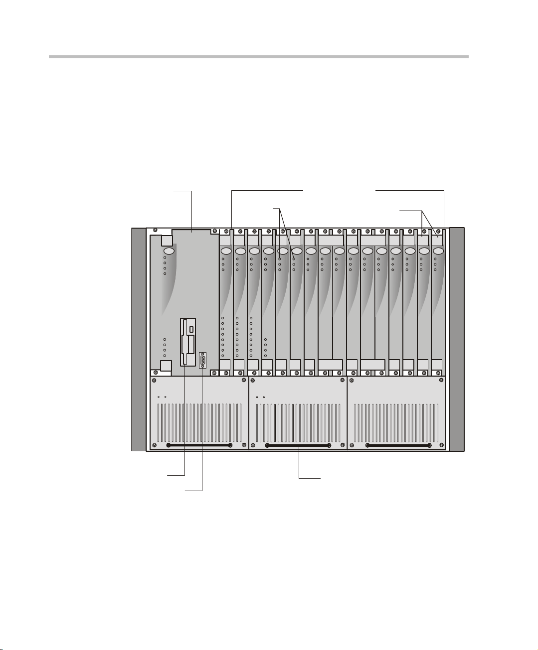
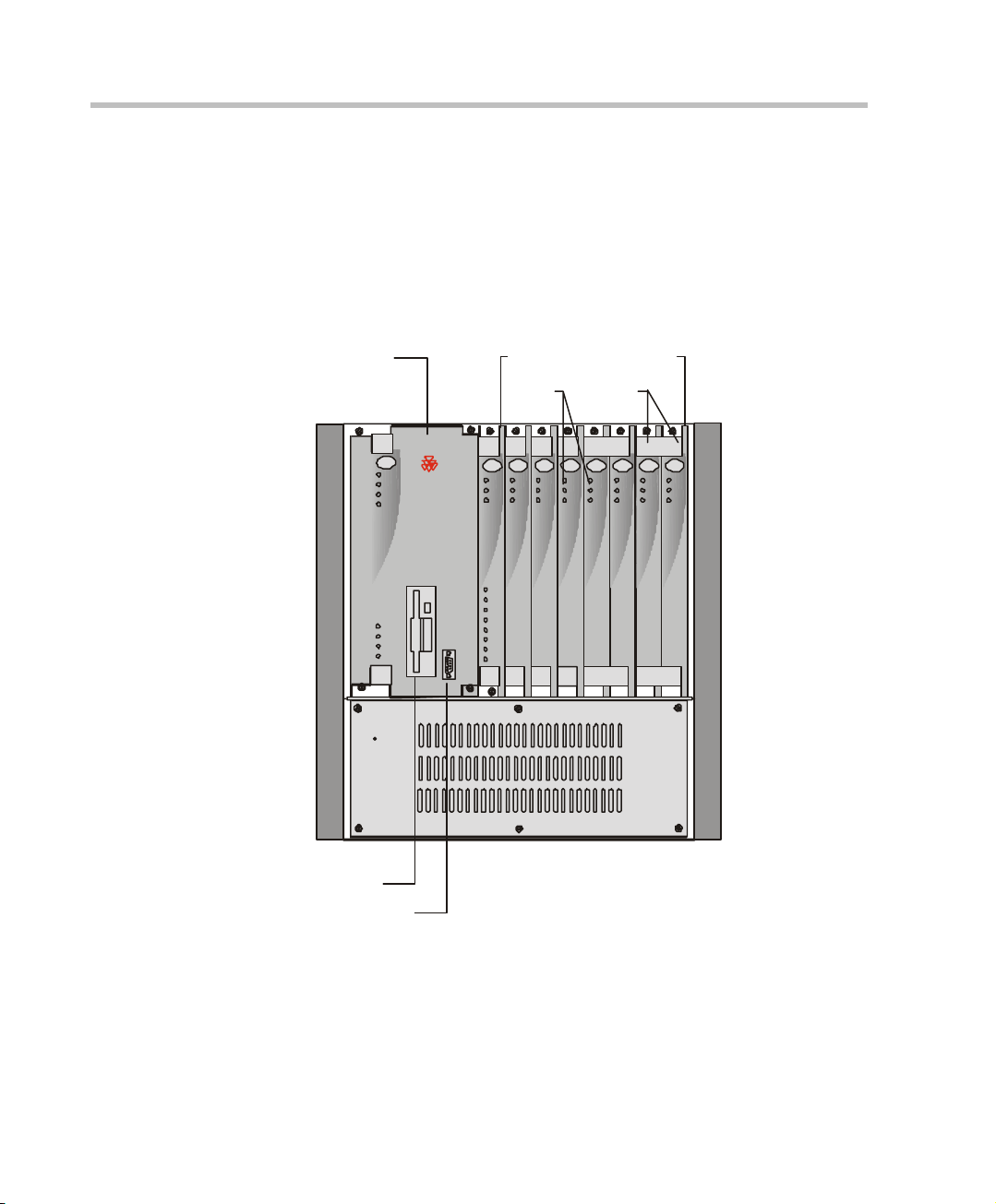
Figure 2-1 shows the front panel of the MGC-100. The front panel provides
access to the Main Control Module, the Functional Modules, and the Power
Supply Modules. Status LEDs on the Main Control Module, Functional
Modules, and Power Supply Modules indicate the status of the system.
Main
Control
Module
Disk Drive
COM Port
PWR
IN
OUT
Functional Modules
LEDs
CONT
ACCORD
Critical
Major
Minor
MGC-100
L0
Power
L1
L2
L3
Stby
Fail
Active
Line 1
Line 2
Line 3
Line 4
Line 5
Line 6
Line 7
Line 8
NET-8NET-8 NET-8
Stby
Stby
Fail
Fail
Active
Active
Line 1
Line 1
Line 2
Line 2
Line 3
Line 3
Line 4
Line 4
Line 5
Line 5
Line 6
Line 6
Line 7
Line 7
Line 8
Line 8
PWR
IN OUT
E1 MUX MUX DA TA DATA
Stby
Stby Stby
Stby
Fail
Fail Fail
Fail
Active
Active Active
Active
Line A
Line B
VIDEO VIDEO VIDE O AUDIOVIDEO AUDIO
Stby
Stby Stby
Fail
Fail Fail
Active
Active Active
PWR
IN OUT
Ejectors
Stby
Fail
Active
Stby Stby
Fail Fail
Active Active
UDIO
UDIO
Stby
Stby
Stby
Fail
Fail
Fail
Active
Active
Active
Power Supply Module Handle
Figure 2-1: MGC-100 Front Panel
2-2
Page 17
MGC-50/MGC-100 Getting Started Guide
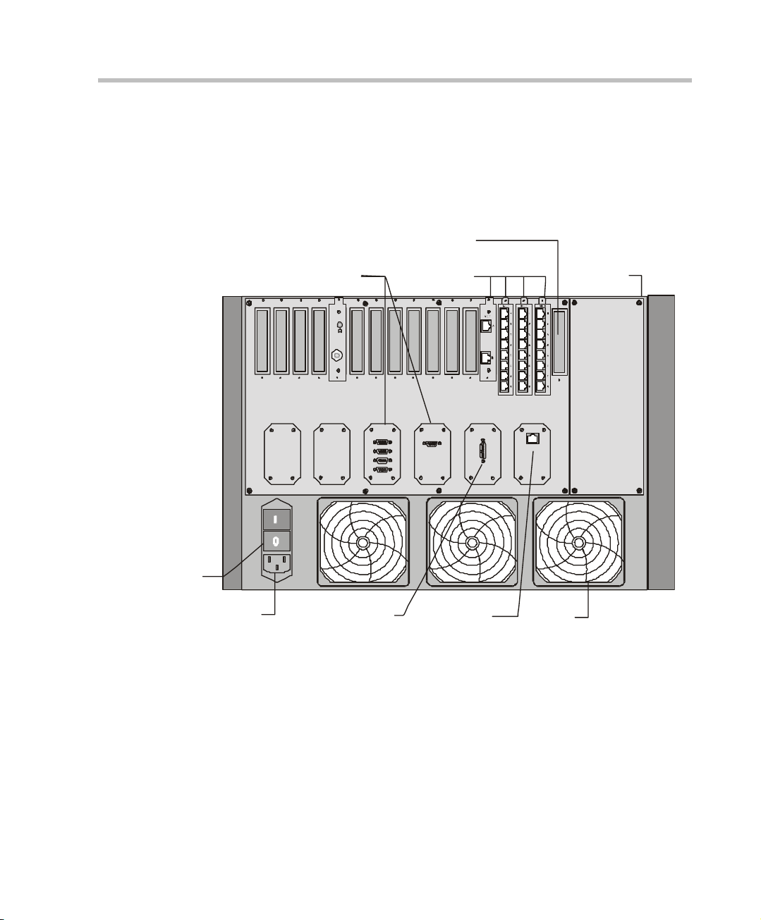
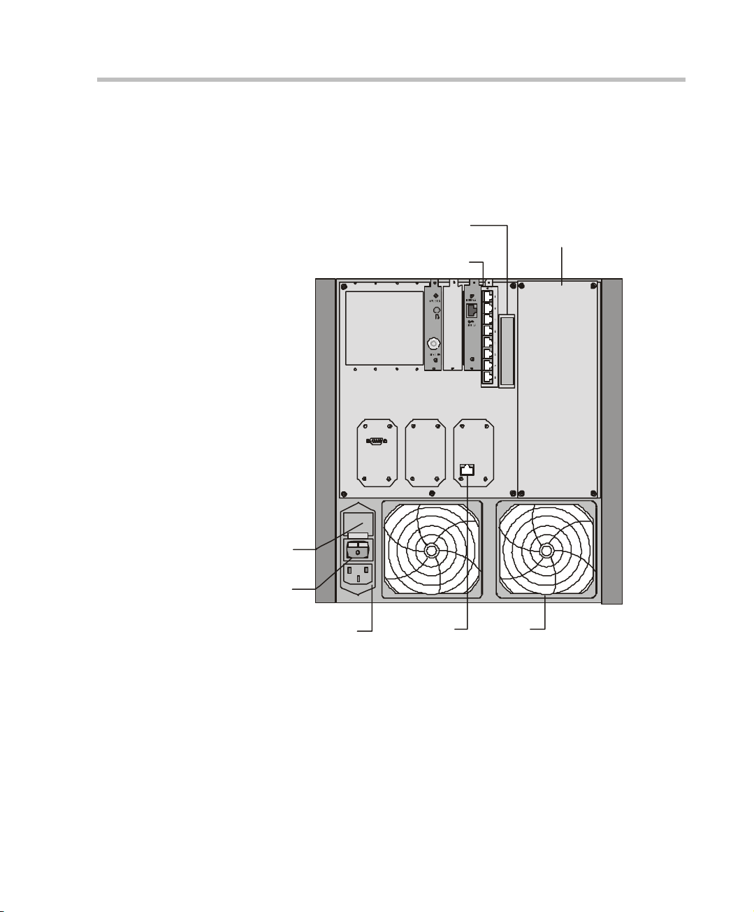
Figure 2-2 shows the rear panel of the MGC-100. The rear panel provides
access to the network I/O card connectors. I/O cards are inserted via the rear
panel. In addition, the rear panel houses the main power switch, AC inlet,
fans, the fuse, additional communications ports and alarm ports. The Alarms
port provides dry contacts for critical, major, and minor alarms.
Slot A
RS232
Connectors
MUSIC
LINE IN
Network
Connectors
10/100 Mbits
Main Control
Module Cover
LANALARMSCOM 1COM
Main Switch
and Circuit Breaker
AC Inlet
Dry Contacts RJ45 Connector
Figure 2-2: MGC-100 Rear Panel with External Connectors
Fan
2-3
Page 18
Chapter 2 - Hardware Description
y
A
A
A
A
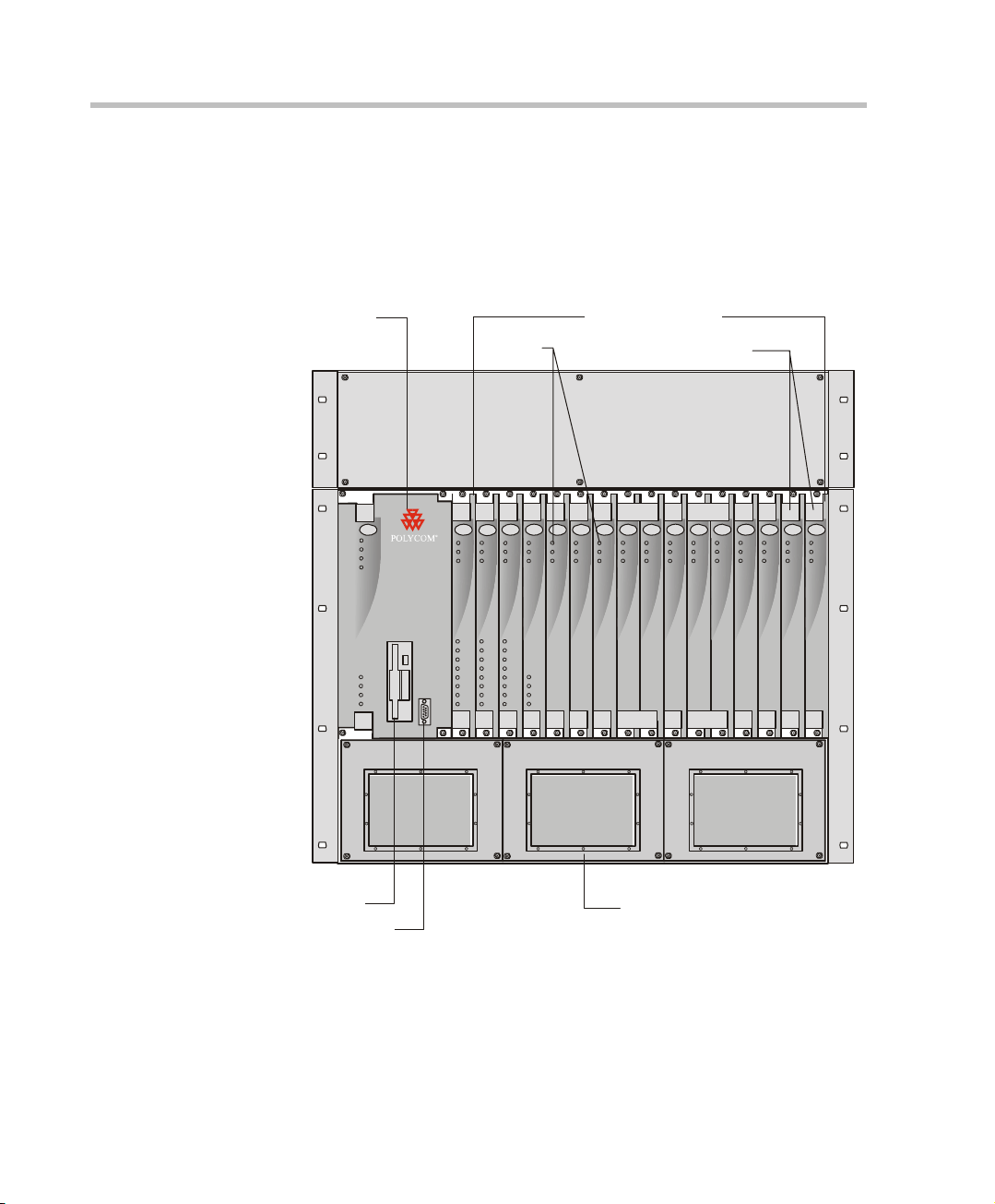
Figure 2-3 shows the front panel of the MGC-100 NEBS Standard. The front
panel, as in the MGC-100, provides access to the Main Control Module, the
Functional Modules, and the P ower Supply Modul es . Status LEDs on the
Main Control Module, Functional Modules, and Power Supply Modules
indicate the status of the system.
.
Main
Control
Module
LEDs
Functional Modules
Ejectors
CONT
Critical
Major
MGC-100
Minor
L0
Power
L1
L2
L3
Stby
Fail
Active
Line 1
Line 2
Line 3
Line 4
Line 5
Line 6
Line 7
Line 8
NET-8NET-8 NET-8
Stby
Fail
Active
Line 1
Line 2
Line 3
Line 4
Line 5
Line 6
Line 7
Line 8
NET-E1
MUX MUX DATA DATA VIDEO VIDEO VIDEO AUDIOVIDEO AUDIO
Stby
Stby
Stby Stb y
Stby
Fail
Fail
Fail Fail
Fail
Active
Active
Active Active
Active
Line 1
Line 2
Line 3
Line 4
Line 5
Line A
Line 6
Line 7
Line B
Line 8
Floppy Disk Drive
COM Port
Figure 2-3: MGC-100 NEBS Standard Front Panel
Stby
Stby Stb y
Fail Fail
Active Active
Stby
Fail
Active
Fail
Active
Stby Stb y
Fail Fail
Active Active
UDIO
Stby
Stb
Fail
Fail
ctive
Active
Power Supply Module Cover
UDIO
Stby
Fail
ctive
2-4
Page 19
MGC-50/MGC-100 Getting Started Guide
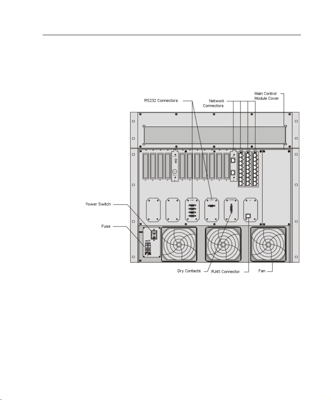
Figure 2-4 shows the rear panel of the MGC-100 NEBS Standard.
The rear panel, as in the standard MGC-100, provides access to the
network I/O card connectors and fans. I/O cards are inserted via the
rear panel.
Figure 2-4: MGC-100 NEBS Standard Rear Panel with External Connectors
2-5
Page 20
Chapter 2 - Hardware Description
MGC-50 Components Location
Figure 2-5 shows the front panel of the MGC-50. The front panel provides
access to the Main Control Module, the Functional Modules, and the Power
Supply Module. Status LEDs on the Main Control Module, Functional
Modules, and Power Supply Module indicate the status of the system.
Control
Module
Floppy Disk Drive
COM Port
Main
PWR
OUT
Functional Modules
LEDs
CONT
Critical
POLYCOM
Major
Minor
MGC-50
L0
Power
L1
L2
L3
MG-323PRI-8
Stby
Fail
Active
Line 1
Line 2
Line 3
Line 4
Line 5
Line 6
Line 7
Line 8
Ejectors
VIDEOVIDEO VIDEOVIDEOAUDIOAUDIO
StbyStby
Stby
Stby
Fail
Fail
Active
Active
StbyStbyStby
FailFail
FailFailFail
ActiveActive
ActiveActiveActive
2-6
Figure 2-5: MGC-50 Front Panel
Page 21
MGC-50/MGC-100 Getting Started Guide
Figure 2-6 shows the rear panel of the MGC-50. I/O cards are inserted via the
rear panel. The rear panel also provides access to the fans, power supply
module, network connections, additional communications ports, the main
power switch, AC inlet, and fuse.
Fuse
Main Switch
AC Inlet
COM 1
IO Card
RJ45
Connector
Slot A
Main Control
Module Cover
LAN
Fan
Figure 2-6: MGC-50 Rear Panel with External Connector
2-7
Page 22

Chapter 2 - Hardware Description
MGC Unit Components
The following table describes the MGC components. A more detailed
description is found in the MGC-50/MGC-100 Hardware & Installation
Manual.
Table 2-1: MGC Component Description
MGC
Component
Control Module The Main Control Module performs the conference setup
Backplane The backplane is an electronic circuit board into which
Power Plane The Power Plane is a conducting layer provi ding power to
Power Supply
Modules
Fans Three (MGC-100) or two (MGC-50) fans are mounted at
Description
and termination and resource allocation in both the
MGC-100 and the MGC-50.
The Network Interface Module, the Ma in Co ntro l Mod ule ,
Functional Modules, and I/O cards are plugged so the
various modules can communicate with each other. The
Backplane is base d on t he “unive rsal slot ” concept, w here
any card can be inserted in any slot.
the components. It is part of the Backplane and is
designed to accommodate hot swapping of power
supplies.
The Power Supply Module is loc ated undernea th the Main
Control Module and the Functional Modules and is
connected to the backplane. It provides power to the
Backplane by means of a power bus. Both MGC units
(MGC-100 and MGC-50) operate at 100-240 volts AC 50/
60 Hz.
the bottom of the rear panel.
2-8
Alarms Port In the MGC-100 an Alarms port is located on the Main
Control Module. The d r y c ontacts on the rear panel of the
MGC-100 are for connecting to the customer’s alarm
system.
Page 23

Table 2-1: MGC Component Description
MGC-50/MGC-100 Getting Started Guide
MGC
Component
Functional
Modules
Input/Output (I/O)
Cards
Description
The Functional Modules, also known as cards, perform
the various audio, video, and data processing functions
for the MGC unit. Both the MGC-100 and the MGC-50
use the same functional modules.Any module can be
inserted into any slot and servicing can be performed
while the system is in operation. The MGC-100 can
contain up to 16 Functi onal Mod ules and the MGC -50 can
contain up to 8 Functional Modules.
Input/Output (I/O) Cards connect the Functional Modules
to external systems and networks.
2-9
Page 24

Chapter 2 - Hardware Description
2-10
Page 25
Initial System Configuration
3
Initial IP
Configuration
Installing the
MGC Manager
Start ing the MGC
Manager
Defining an MCU
Connecting
to an MCU
Configuring the
Network Services
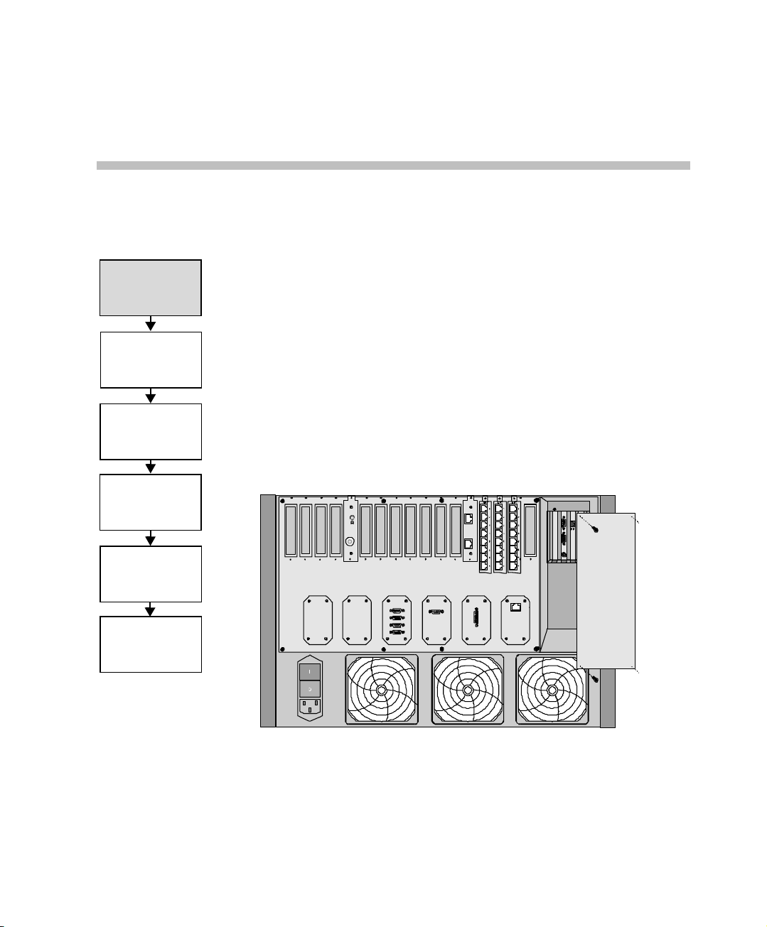
The MGC-50/MGC-100 requires basic configuration before you can start
running conferences.
Initial IP Configuration
The system is shipped with a default IP address: 129.254.4.8. Ordinarily,
you need to change the MCU’s default IP address to the IP address
appropriate for the site's LAN. This section describes how to modify it using
a monitor and terminal to connect directly to the MCU.
To modify the MCU default IP address to the site’s IP address:
1. Remove the Main Control Module cover.
MUSIC
LINE IN
NET
A
B
LANALARMSCOM 1COM
10/100 Mbits
K
/
R
N
L
T
KB0
Figure 3-1: MGC-100 Rear Panel
3-1
Page 26
MGC-50/MGC-100 Getting Started Guide
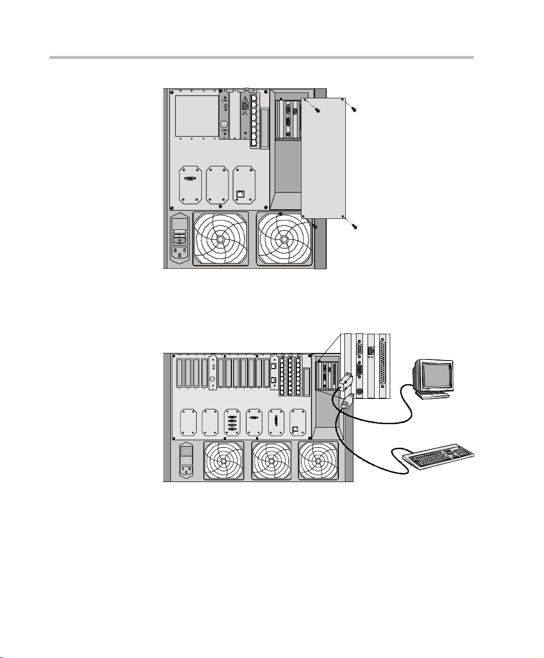
Figure 3-2: MGC-50 Rear Panel
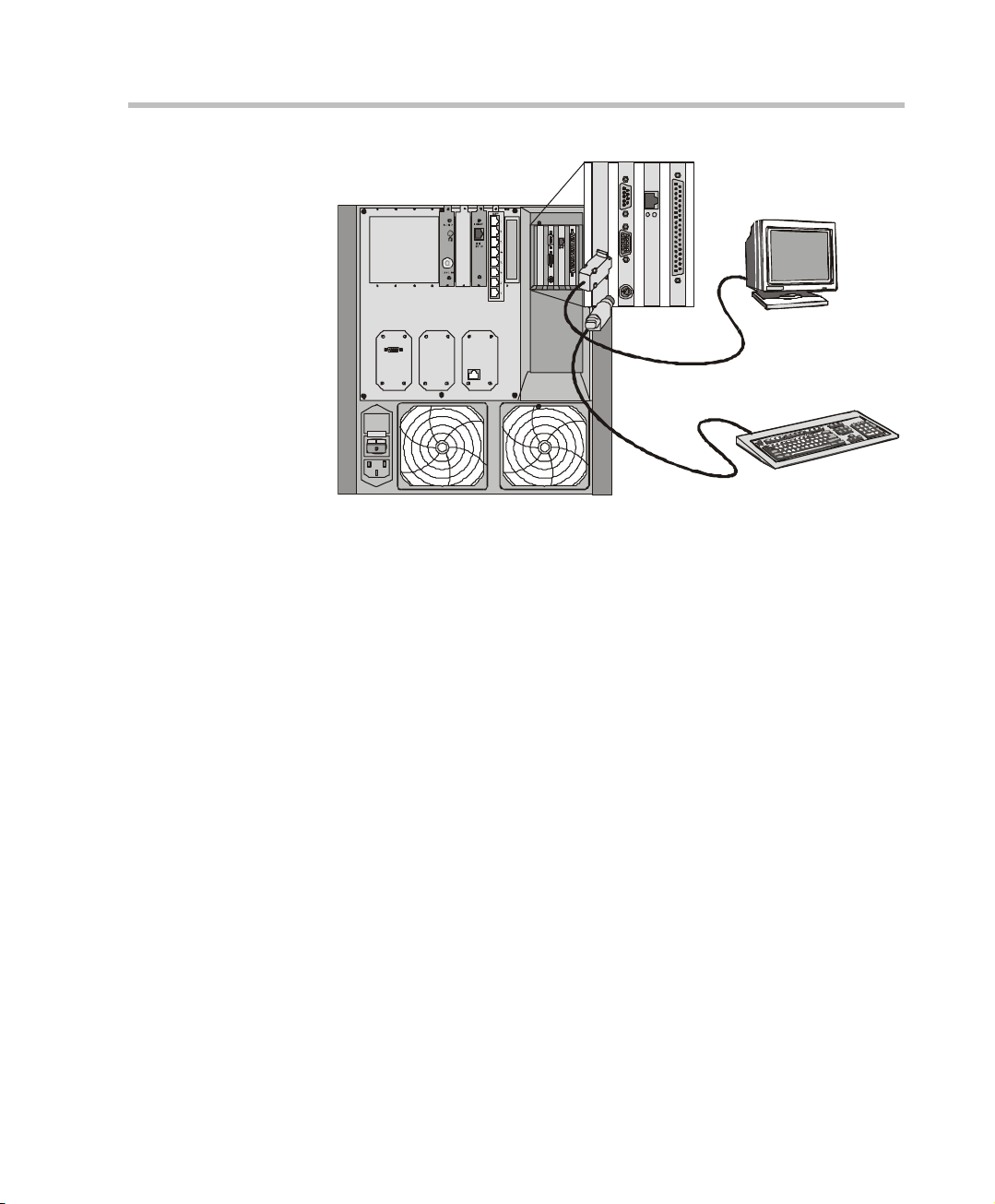
2. Connect a monitor and the keyboard to the appropriate connectors in the
MCU.
R
/
LNK
T
KB0
LANCOM 1
3-2
R
MUSIC
LINE IN
NET
A
B
LANALARMSCOM 1COM
K
N
L
T/R
KB0
/
LNKT
KB0
Figure 3-3: Attaching the Monitor and Key Board to the MGC-100
Page 27
Chapter 3 - Initial System Configuration
NK
L
T/R
R
/
LNK
T
KB0
KB0
COM 1
LAN
Figure 3-4: Attaching the Monitor and Key Board to the MGC-50
3. Insert the DOS diskette into the MCU diskette drive.
4. Reset the MCU (by turning it off and then on), or if it is turned off, turn it
on. The command line is displayed.
5. Type C:\>dir mcu\cfg and press Enter.
6. Type C:\>\mcu\cfg>edit lan.cfg and press Enter.
The Edit screen opens displaying the IP configuration parameters.
7. Move the cursor to the appropriate line and enter the new IP Address.
If required, modify the Subnet Mask and the Default Gateway values.
8. Save the new IP configuration and exit the DOS editor.
9. Disconnect the monitor and keyboard from the MCU, and mount the
Main Control Module cover back to its place.
10. Restart the MCU.
3-3
Page 28
MGC-50/MGC-100 Getting Started Guide
Installing the MGC Manager
To configure and control the MGC unit and to setup conferences you must
Initial IP
Configuration
Installing the
MGC Manager
Start ing the MGC
Manager
Defining an MCU
Connecting
to an MCU
install the MGC Manager software on a customer-provided computer or
server. Up to 30 MGC Manager-enabled PCs can be connected to each
MGC-50 or MGC-100. A single MGC Manager-enabled PC can manage
multiple MGC systems.
To install the MGC Manager software:
1. Insert the software CD into the CD drive.
2. On the Start menu, click Run.
The Run dialog box opens.
3. Type D:\SETUP (where D is the name of the CD drive), and then click
OK.
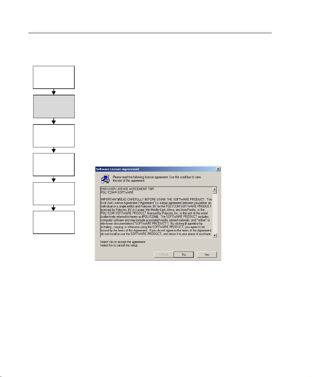
The installation wizard starts and the License Agreement window opens.
Configuring the
Network Services
3-4
4. Click Yes to agree to the terms of the agreement or No to exit the
installation.
If you clicked Yes, the Welcome window opens.
5. Click Next.
Page 29
Chapter 3 - Initial System Configuration
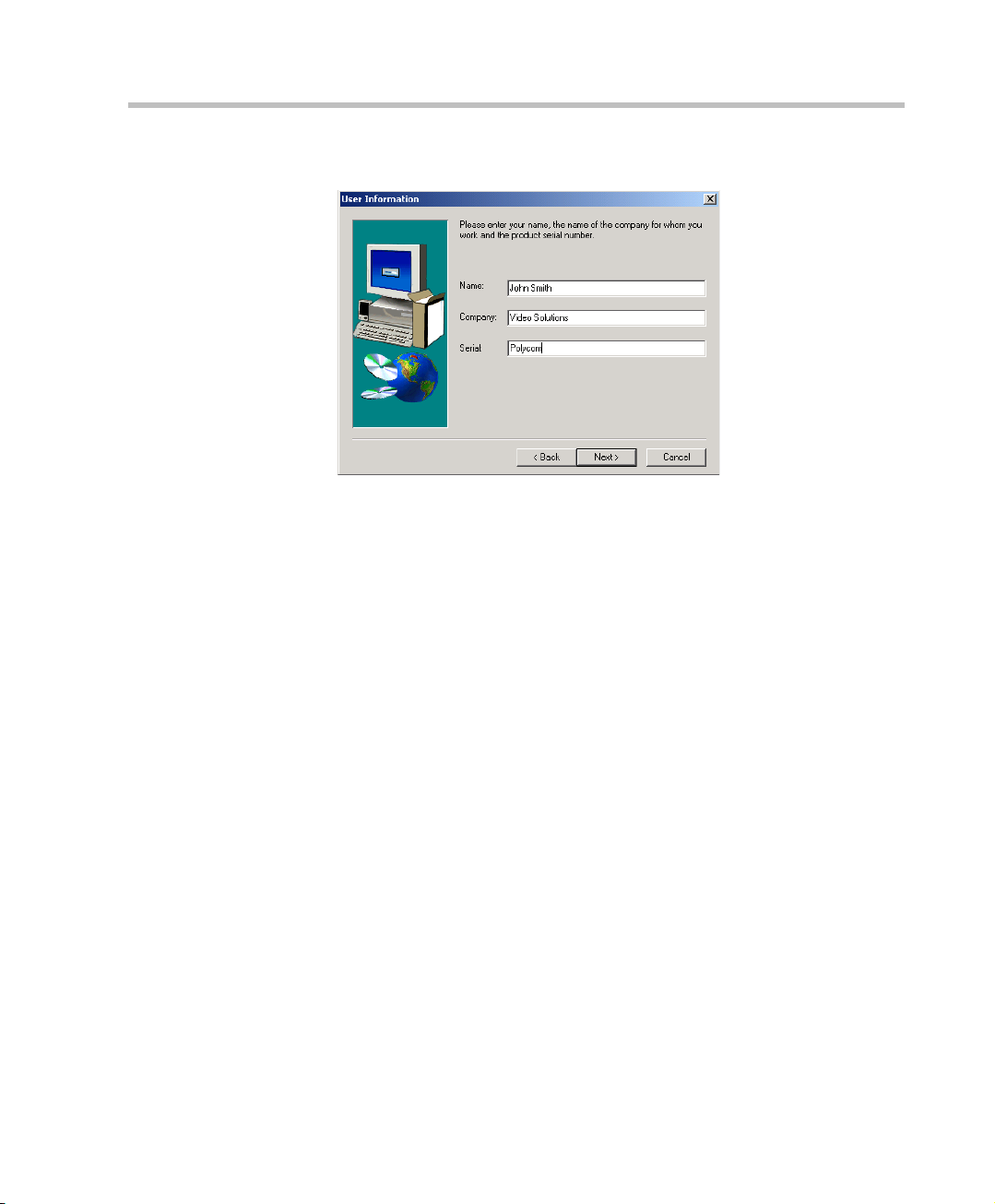
The User Information screen opens.
6. Enter your name and the name of your company in the appropriate
boxes.
For a standard installation, enter Polycom in the Serial box.
7. Click Next.
Follow the on-screen instructions to complete the installation process.
At the end of the installation procedure, the Setup Complete window
opens.
8. Click Finish.
The MGC Manager software is now installed on your computer.
3-5
Page 30
MGC-50/MGC-100 Getting Started Guide
Starting the MGC Manager
Once the MGC Manager application is installed, it can be used to set up and
Initial IP
Configuration
Installing the
MGC Manager
Starting the MGC
Manager
Defining an MCU
Connecting
to an MCU
monitor multipoint audio and video conferences, and to perform system
configuration activities for the MGC unit to which it connects.
To start the MGC Manager application:
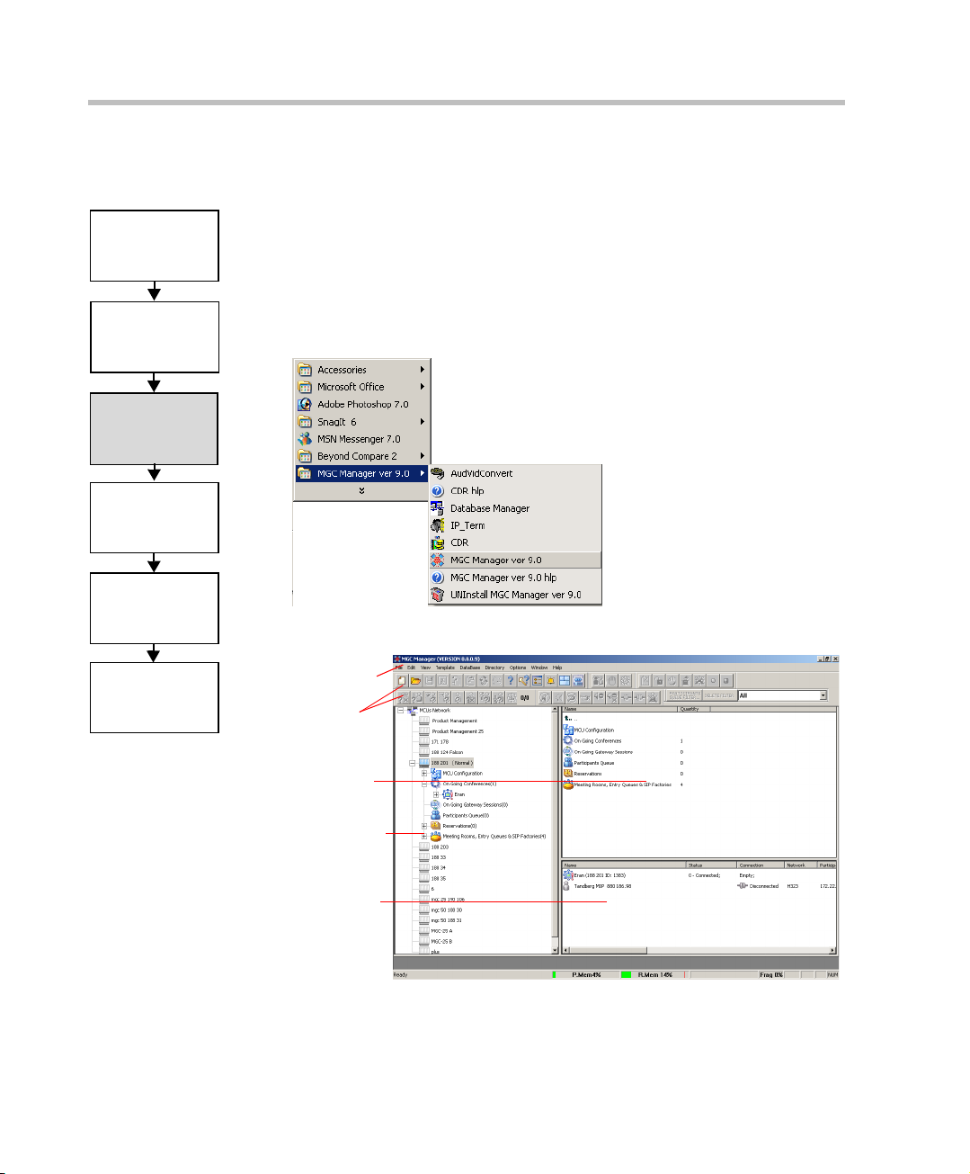
• On the Start - Programs menu, click MGC Manager ver 9.0, and then
click MGC Manager ver 9.0.
The MGC Manager main window opens.
Configuring the
Network Services
3-6
Main Menu
Toolbars
Status pane
Browser
pane
Monitor pane
Page 31

Defining an MCU
To manage and control the MGC unit from the MGC Manager application it
Initial IP
Configuration
must be added to the MCUs Network list. The MCU IP address must match
the IP address defined in the MCU. For details, see “Initial IP Conf ig ur at io n”
on page 3-1
Chapter 3 - Initial System Configuration
.
Installing the
MGC Manager
Starti ng the MGC
Manager
Defining an MCU
Connecting
to an MCU
Configuring the
Network Services
To define an MCU Connection:
1. In the Browser pane, right-click the MCU Network icon, and then click
New MCU.
The Add MCU dialog box opens.
2. In the Name box, enter a name that clearly identifies the MCU using up
to 20 characters (no comma, period or semicolon).
3. In the IP Address box, enter the IP Address of the MCU (as defined
during the Initial IP Configuration).
4. Click OK.
The Add MCU dialog box closes.
The new MCU icon and name appear in the Browser pane.
3-7
Page 32

MGC-50/MGC-100 Getting Started Guide
Connecting to an MCU
Initial IP
Configuration
Installing the
MGC Manager
Start ing the MGC
Manager
Defining an MCU
Connecting
to an MCU
Configuring the
Network Services
Once the MCU connection parameters are defined, the MGC Manager can be
connected to all defined MCUs simultaneously. The MGC Manager allows
you to set up conferences, make reservatio ns, monitor On Going Co nferences
and perform other activ ities on se veral MCUs. Th e MGC Manager repo rts the
status of each MCU connection.
To connect the operator workstation to an MCU:
1. In the Browser pane, expand the MCUs Network tree.
A list of MCUs appears below the MCUs Network icon.
2. Double-click the MCU icon.
Alternatively, right click the MCU icon, and then click Connect.
The Logon dialog box opens.
3-8
3. Enter your Login Name and Password, and then click OK.
Note that each MCU is initially configured with a defaul t operator whose
Login and Password are both POLYCOM. Additional operators can be
defined. For more details, see the MGC Administrator’s Guide,
Chapter 6.
Page 33

Chapter 3 - Initial System Configuration
Configuring the Network Services
The Network Services include the parameters of the networks connected to
Initial IP
Configuration
the MCU. If no Network Services have been configured, depending on your
system configuration, the appropriate Network Service must be configured.
This section describes the configuration of both IP and ISDN networks.
Installing the
MGC Manager
Starti ng the MGC
Manager
ISDN Network Service
The Net-2/4/8 Network Interface module installed in the MCU interfaces
For information about de fining T1-CAS, MPI, N FAS ISDN, Leased lines
ISDN and additional ISDN and IP Network Services, or modifying
existing Network Services, refer to the MGC Administrator’s Guide,
Chapter 3.
between the MGC unit and the ISDN switch. The Network Service is u s e d to
define the properties of the switch and the ISDN lines running from the
Defining an MCU
switch to the ISDN Network Interface module. Each group of ISDN lines
having the same characteristics and originating from the same ISDN switch,
will be assigned to the same Net w ork Service.
Connecting
to an MCU
IP Network Service
The IP Network Service defines the properties of the IP network used for
connecting IP endpoints to the conference and the IP cards (installed in the
MCU) to which the network is connec ted. Several of the networ k components
Configuring the
Network Services
are used by both H.323 and SIP endpoints to connect to the conference, and
the same IP card is used for H.323 and SIP connections. One IP Network
Service, therefore, can be defined for both H.323 and SIP environments as
well as an H.323-only or a SIP-only network service.
Defining an ISDN Network Service
The MCU can be connected to ISDN lines provided by different carriers.
Each carrier has unique characteristics, and may have different pricing
programs. T o use th ese lines, together with the carrier’s special prog rams, you
must first obtain the relevant information from the carrier and then define
their parameters in the MGC Manager’s application.
To define a New ISDN Network Service:
1. Connect the MGC Manager to the MCU.
2. In the Browser pane, expand the MCU tree to list its options.
3-9
Page 34

MGC-50/MGC-100 Getting Started Guide
3. In the MCU tree, expand the MCU Configuration tree.
4. Expand the Network Services tree.
5. Right-click the Network Services - ISDN icon, and then click New
Network Service.
3-10
The new Network Service configuration wizard - Settings tab opens.
Page 35

Chapter 3 - Initial System Configuration
6. In the Settings dialog box, define the following parameters:
Table 3-1: Settings Dialog Box Options
Field Description
Net Service Name Enter a unique name using up to 20 characters to
identify the Network Service. The Service
Provider’s name can be used.
Span Type Select the span type from the drop-down list; select
either T1 (usually in the U.S.), or E1 (usually in
Europe).
Service Type Select PRI (Primary Rate Interface) for all ISDN
lines that are not leased lines. To define ISDN
Leased Lines service, refer to the MGC
Administrator’s Guide, Chapter 3.
NFAS To define an ISDN NFAS Se rvice, refer to t he MGC
Administrator’s Guide, Chapter 3.
7. Click Next.
The PRI Settings dialog box opens.
3-11
Page 36

MGC-50/MGC-100 Getting Started Guide
8. In the PRI Settings dialog box, define the following parameters:
Table 3-2: PRI Settings Dialog Box Options
Field Description
Default num-type The num-type defines how the system handles the
Num-plan For video conferencing purposes, select the ISDN
Voice Indicate the frequency of the data being sent. For
Sub Services Some service pro viders (carriers ) may have seve ral
dialing digits. I f you w ant the ne twork to in terpret the
dial digits for routing the call, select Unknown.
option.
practical purposes, the Voice option is set to 3.1
KHz as it is the more widely used frequency.
service pr ograms that can be used. They may also
use a backup service provider in case of
malfunction in the ISDN network. The Sub-Service
list displays the list of currently defined sub
services.
To define a service program to be used, click the
Add button. The Sub-Service dialog box opens.
To remove a service program from the list, highli ght
it in the list box and click the Del button.
To set a service program as the default, highlight it
in the list box and click the Default button.
T o edit the p arameters of a sub-s ervice, double-cl ick
its name in the sub-services list. The Sub-Service
dialog box opens.
3-12
9. If you are not defining a sub-service or if you have completed the
sub-service definition, click Next to continue.
The Span Definition dialog box opens. To continue the definition of the
Network Service without defining a sub service, skip to step 12.
Page 37

Chapter 3 - Initial System Configuration
10. To add or modify the sub-service, in the Sub Service dialog box define
the following parameters:
Table 3-3: Sub Service Dialog Box Options
Field Description
Name Type the name of the sub-service using up to 20
characters. This name identifies the sub-service.
Dial-out Prefix Type the prefix that your PBX needs to dial out in
order to use this service program. Leave this field
blank if a dial-out prefix is not required.
Information
Element
Net Specific Select the desired service program from the
Backup Dial-Out For future release.
For future release.
drop-down list. If no special specification is
required, select the NULL option.
11. Click OK.
The Sub Service dialog box closes and you are returned to the PRI
Settings dialog box (step 9) where you click Next to continue.
3-13
Page 38

MGC-50/MGC-100 Getting Started Guide
12. In the Span Definition dialog box, define the following parameters:
The default valu es di sp lay ed fo r th e Span’s technical param ete rs are appropriate
for most ISDN networks, therefore you skip their definition. The Leased Lines
section of this dialog box is enabled only when defining an ISDN Leased Lines
Service. For more details, refer to the MGC Administrator’s Guide, Chapter 3.
3-14
13. Click Next to continue.
Page 39

Chapter 3 - Initial System Configuration
The Spans and Phones dialog box opens.
To define
a span
The number used
to identify the
MCU
To remove a
span
To define a dial-in phone
numbers range
To delete a
currently
defined dial-in
numbers range
To allocate
dial-in numbers
for Gateway
calls
T o delete
allocated dial-in
numbers for
Gateway calls
This dialog box is used to assign circuit identification numbers and the
dial-in phone number ranges to be used in dial-in conferences. Circuit
orders are automatically assigned to spans. If onl y one service provider is
used, define all the PRI lines here.
The dial-in phone numbers are allocated to the MCU by the service
provider (carrier) and should be obtained from the service provider.
3-15
Page 40

MGC-50/MGC-100 Getting Started Guide
14. Define the Spans and Phones parameters as follows:
Table 3-4: Spans and Phone Dialog Box Options
Field Description
Span Displays the existing definitions of circuit
Dial In Phone Num Lists the phone numbers available for dialing in, as
MCU Number Type a number to identify the MCU when calling the
identification numbers and circuit orders.
Click the plus button to define the new spans.
allocated to the MCU by the service provider.
Click the plus button to define a dial-in phone
range.
participants in dial-out conferences. This number is
part of the dial-in numbers allocated to the MCU by
the service provider, but it cannot be part of the
dial-in phone range.
The MCU Number is also used for dial-in, in
conferences when the Meet Me Per MCU option is
selected as the connection type for participants.
3-16
Gateway Range Displays the dial-in numbers allocated to Gateway
calls. Click the plus button to allocate dial-in
ranges to the gateway. The Gateway Phone
Numbers dialog box opens.
To define the NFAS parameters, see the MGC Administrator’s Guide,
Chapter 3.
Defining Spans
15. To assign circuit identification numbers and orders:
a. In the Spans pane of the Span and Phone dialog box, click the Plus
button.
Page 41

The Add Span dialog box opens.
b. Define the following parameters:
Table 3-5: Add Span Dialog Box Options
Field Description
Chapter 3 - Initial System Configuration
Circuit ID The Circuit Identification is a logical number used to
identify the span to the MGC Manager. This number
is later used to assign the sp an to the ISDN netwo rk
card.
Type an y positiv e integer from 0 to 65535 to b e used
as the circuit identification number in the MGC
Manager.
Note:
If other Network Services are al read y d efi ned , m ak e
sure to use numbers other than those already
assigned to the existing services.
Circuit Order The Circuit Order determines the order in which an
MCU uses the spans to dial out.
c. Once you have defined all the identification numbers click OK.
The Add Span dialog box closes and you are returned to the Spans
and Phones dialog box.
3-17
Page 42

MGC-50/MGC-100 Getting Started Guide
To delete a circuit identification entry:
• In the Spans pane, click the Circuit Identification entry you want to
delete and click the Minus button.
The entry is deleted.
Defining Dial-In Numbers
The numbers to be used for dial-in connections to multipoint conferences are
allocated to the MCU by your service providers.
16. Specify the range of dial-in numbers by entering the first and last
numbers in the range. You can define several ranges for the same span.
a. In the Dial In Phone Numbers pane of the Spans and Phones dialog
box, click the Plus button
The Add Phone Num dialog box opens.
3-18
b. In the First Phone Number box, enter the first number in the range
of dial-in numbers.
c. In the Last Phone Number box, enter the last number in the range of
dial-in numbers.
d. Click OK.
The dialog box closes. You are returned to the Spans and Phones
dialog box. The number range appears in the Dial-In Phone
Numbers list.
e. Repeat steps a-d for each number range you need to enter.
Page 43

Chapter 3 - Initial System Configuration
To delete a dial-in number entry:
• In the Dial In Phone Number pane, click the entry to delete and click the
Minus button.
The entry is deleted.
Defining the Gateway Range
Define the dial-in ranges allocated to Gateway Session using the same
procedure as described for the dial-in numbers allocated to multipoint
conferencing.
The range of dial-in numbers allocated to Gateway calls must differ from the
dial-in number ranges allocated to multipoint conferencing.
For a detailed description, see the MGC Administrator’s Guide, Chapter 3.
Completing the ISDN Network Service Definition
17. Once you have finished filling in all the Wizards screens, click the
Finish button in the Spans and Phones dialog box.
The data you have specified wil l be val id ate d, af t er whi ch the ISDN Network
Service will be added to the list of ISDN network services of the MCU.
Assigning the ISDN Network Service to the ISDN Network Interface Module (Net-2/Net-4/Net-8)
In order to connect the MCU to the ISDN network switch, you must assign
the ISDN Network Service to the appropriate span of the Net-2/Net-4/Net-8
Network Interface module. In addition, you must define which span in the
network interface card will be used as the primary clock. Finally, if the MCU
is not configured to work with a single clock source, you must define which
span will be used as the backup clock to synchronize with the network clock.
To set the MCU to work in a single clock mode, the appropriate flag must be
set in the system.cfg file. For detail s, s ee th e MGC Administrators Guide,
Chapter 5, “Edit “system.cfg.”
3-19
Page 44

MGC-50/MGC-100 Getting Started Guide
To configure the Net-2/Net-4/Net-8 ISDN Network Interface module:
1. In the Browser pane, right-click the slot containing the
Net-2/4/8 card, and then click Properties.
Alternatively, double-click the slot containing the card.
The Card Settings – Common Pa rameters dialog box opens.
2. Click the Net-8 Network Parameters tab.
The Card Settings NET-8 Network Parameters dialog box opens.
3-20
The Net-2/Net-4/Net-8 Network Interface module supports up to eight
PRI connections, depending on the card model installed in the MCU.
These connections may be either T1 or E1. For the system to recognize
the PRI lines that connect to the Network card, you must assign the
Page 45

Chapter 3 - Initial System Configuration
Circuit ID of the PRI li ne defined in Netw ork Service to the appropriate
span in the Card Settings - Net-8 Network Parameters. Not all spans may
be currently in use. In such a case, only the spans being used are
configured.
3. To assign a Circuit ID to the appropriate span:
a. In the Span n box (where n is the span number on the Net-2/Net-4/
Net-8 module to which the PRI line is connected), clear the Null
Configuration check box to enable the span.
b. In the Circuit ID box, enter the circuit ID as defined in the ISDN
Network Service-Span and Phones dialog box. According to the
selected Circuit ID, the ISDN Network Service is assigned to the
network card. Each span can be assigned a different Network
Service.
c. Click Apply.
The name of the network service appears in the Service Name box.
4. Click OK.
To configure a Net-2/Net-4/Net-8 span as prim ary o r ba ckup clock:
Any of the configured spans can be set as the “Master Clock,” that
synchronizes the system clock to t he network clock, or “backup cl ock”, that is
used if the master clock fails.
For more information about clocking, see the MGC Administrator’s Guide,
Chapter 5.
1. In the Browser pane, expand the Net-2/Net-4/Net-8 ISDN card to display
its units in the Browser and Status panes. Each unit represents a span in
the ISDN Network card.
3-21
Page 46

MGC-50/MGC-100 Getting Started Guide
2. Right-click the unit (span) to configure and select one of the clocking
options:
Table 3-6: Net-2/Net-4/Net-8 Unit Clocking Options
Option Description
Set as Primary
Clock Source
Cancel Primary
Clock Source
Set As Backup
Clock Source
Cancel Backup
Clock Source
Sets this unit as the primary clock source.
Stops this unit from acting as the primary clock
source.
Sets this unit as the backup clock source.
Stops this unit from acting as the backup clock
source.
3. After setting the c loc k sour ce, a Warning message box opens, instructing
you to reset the MCU.
The configuration changes take effect only after the next MCU reset or
start up and they are shown in the Configured Clock column in the Status
pane.
3-22
Page 47

IP Network Services
The IP Network Service defines the properties of the IP network used for
connecting IP endpoints to the conference and the IP cards (installed in the
MCU) to which the network is connec ted. Several of the networ k components
are used by both H.323 and SIP endpoints to connect to the conference, and
the same IP card is used for H.323 and SIP connections. Therefore one IP
Network Service can be defined for both H.323 and SIP environments as
well. However, you can define the Network Service to be H.323-only to be
used to connect only H.323 endpoints or SIP-only to connect only SIP
endpoints.
To define an IP Network Service:
1. In the Browser pane, expand the MCU tree.
2. Expand the MCU Configuration tree.
3. Expand the Network Services tree.
4. Right-click the Network Services – IP icon, and then click New IP
Service.
Chapter 3 - Initial System Configuration
3-23
Page 48

MGC-50/MGC-100 Getting Started Guide
The new Network Service configuration wizard - Setting dialog box
opens.
3-24
5. Define the following fields:
Table 3-7: Settings Options
Field Description
Service Name Specify the service name using up to 20 characters.
Service Type IP services use an Ethern et networ k, wh ich i s a LAN
standard. The Service Type cannot be changed.
Protocol
• H.323 - For an H.323-only network service.
• SIP - For a SIP-only network servic e.
• Both - For an integrated IP service. Both H.323
and SIP participants can connect to the MCU
using this service.
Page 49

Table 3-7: Settings Options
Field Description
Network
Chapter 3 - Initial System Configuration
DHCP-Obtain IP
Address
Automatically
Select this check box to use a DHCP server for
automatic assignment and tracking of IP addresses
to the conferencing devices. When the DHCP server
is used, the IP address of the card appears as
0.0.0.0.
You may prefer not to select this check box if you
need to:
• Establish a static IP address.
• When dialing in directly to the card, using the
card’s IP address.
Subnet Mask Enter the subnet mask of the MCU’s IP card. If the
DHCP is used, the subnet mask is automa tic all y
retrieved from the DHCP server and cannot be
modified. The detected number appears in the
card’s Properties-Settings-IP Network Parameters
box.
Default Router Enter the IP address of the default router. If the
DHCP is used, the IP address is automatica lly
retrieved from the DHCP server and cannot be
modified.
Static Routes
Routes Table Displays the list of static routes currently defined in
the system. Up to five routes can be defined in
addition to the Default ro ute r. The order in which the
routers appear in this list determines the orde r in
which the system will look for the endpoints on the
various networks, if not found on the local LAN.
To add a router to the Static Routes table, click the
plus (+) button. For more details see “Defining Static
Routes” on page3-26. To delete a router from the
Static Routes table select the router to remove, and
then click the minus (-) button.
Y ou can define one router with diff eren t des tin ati ons .
3-25
Page 50

MGC-50/MGC-100 Getting Started Guide
Table 3-7: Settings Options
Field Description
Quality Of Service
Quality Of Service Quality of Service (QoS) is an effort to guarantee in
Defining Static Routes
6. To define a static route:
a. Click the plus (+) button.
The Add Rout e dialog box opens.
advance the quality of data transmission over the
network. To change the defaults click the Quality of
Service button. For more information see “Defining
Quality of Service” on page 3-27.
3-26
b. Define the following fields:
Table 3-8: Add Router Options
Field Description
Router IP Enter the IP address of the router in its subnetwork.
Remote IP Enter the IP address of the packet destination.
If Host is selected in the Type field, enter the IP
address of the endpoint.
If Network is selected in the Type field, enter the
components of the IP address indicating the
segment of the other network.
Page 51

Chapter 3 - Initial System Configuration
Table 3-8: Add Router Options (Continued)
Field Description
Type Select the typ e of router connection:
Network – defines a connection to a router segm ent
in another network.
Host – defines a direct connection to an endpoint
found on another network.
c. Click OK.
The system returns to the Settings dialog box, displaying the added
static route.
Defining Quality of Service
7. To define Quality of Service parameters:
a. Click the Quality of Service button.
The QoS of Ethernet Service dialog box opens.
b. Define the following fields:
Table 3-9: QoS of Ethernet Service Options
Field Description
Enable Select the Enable check box to implement QoS for
IP packets.
When cleared, QoS is not implemented.
3-27
Page 52

MGC-50/MGC-100 Getting Started Guide
Table 3-9: QoS of Ethernet Service Options (Continued)
Field Description
DiffServ and
Precedence
DiffServ and Precedence are two methods for
encoding the packet’s priority in the packet header.
If you are not sure which QoS policy your router
supports, select Precedence combined with None
in the TOS field.
• Select DiffServ when the network router uses
DiffServ for priority encoding).
Note: If you select DiffServ but your router does
not support this standard, IP packets queue on
the same communication links with data packets
greatly increasing the latency and jitter in their
delivery.
• Select Precedence when the network router
uses Precedence for priority encoding, or when
you are not sure which method is used by the
router.
Audio and Video You can prioritize audio and video IP packets to
ensure that all participants in the conference hear
and see each other clearly.
Select the desired priority.
The recommended priority for both audio and video
is 4 to ensure that the delay for both packets is the
same and audio and the video packets are
synchronized.
3-28
TOS Type of Service (TOS) defines optimization tagging
for routing the con fere nce s audio and video packets.
• Delay – The recommended default for video
conferencing.
• None – No optimization definition is applied.
Select None if you do not know whic h sta ndard you r
router supports.
c. Cli ck OK to apply your settings and return to the Settings dialog
box.
Page 53

8. In the Settings dialog box, Click Next.
The DNS Settings dialog box opens.
Chapter 3 - Initial System Configuration
For H.323 conferencing, DNS can be used for gatekeeper discovery
using the gatekeeper host name. Using NAT Traversal, the DNS is
queried for the NAT server IP address used for allocating the public
(external) IP addresses to the cards for the conferencing session.
For SIP conferencing, domain names are required and therefore it is
recommended to enter the detai ls of the DNS server and the local domain
name. The DNS is also used if SIP Server discovery is applied. The
system decides whether to use the DHCP or the DNS server for
auto-discovery with preference to the DNS server.
3-29
Page 54

MGC-50/MGC-100 Getting Started Guide
9. Define the following parameters:
Table 3-10: DNS Settings Options
Field Description
Use DNS Servers Select:
DNS Server Addresses
• Off – DNS servers are not used in the network.
• Specify – to manually set the IP address of the
DNS servers.
• Auto – to automatically detect the DNS IP
address, if the DNS Server is defined in the
DHCP and the DHCP -obtain IP Address
Automatically option was selected in the Settings
tab.
Primary DNS
Server IP Address
Secondary/Tertiary
DNS Server IP
Address
DNS Name
Local Domain
Name
10. Click Next.
If Specify was selecte d, this field is mand atory. Enter
the IP address of the primary DNS server.
If Specify was selected, enter the IP address(es) of
the next DNS server in line to resol ve domain names
as a fallback for the primary DNS server.
These fields are optional.
Enter the domain name where the MCU is installed.
The name of the domain includes the host part of
URL or URI, for example, polycom.com.
3-30
Page 55

The H.323 dialog box opens.
Chapter 3 - Initial System Configuration
This dialog box is skipped when defining a SIP-only Network Service.
11. Define the following parameters:
Table 3-11: H.323 Parameters
Field Description
Forwarding Select this check box to enable Forwarding.
Forwarding enables the MCU to indicate the IP
address of another card for hand ling the incoming
call when the first card is busy.
Note: It is not recommended to use Forwarding
when using either Board Hunting or Pseudo
Gatekeeper modes.
3-31
Page 56

MGC-50/MGC-100 Getting Started Guide
Table 3-11: H.323 Parameters (Continued)
Field Description
Gatekeeper
Use Gatekeeper
• Off – select this option if a gatekeeper is not
present in your network. In this case, the MCU
uses the IP addresses for dial out and the
endpoints use the IP addresses of the MCU IP
cards for dial-in.
• Specify – to manually define the IP address of
the preferred and alternate gatekeepers.
• Auto – to retrieve the IP address of the preferred
and alternate gatekeepers from the DHCP, if they
are defined in the DHCP and the DHCP option is
enabled.
Preferred
Gatekeeper IP
Address or Name
Alternate
Gatekeeper IP
Address or Name
Port Displays the port number (1719) used for
Service Mode Select the mode in which the gatekeeper routes calls
If you have selected Specify, enter either the
gatekeeper’s host name (if the DNS server is
enabled and the gatekeeper is registered with the
DNS), or IP address.
If you have selected Specify, enter the host name or
IP address of the alternate gatekeeper.
communication between the MCU and the
gatekeeper.
from a card without free ports to the card with
available resources. If there is no gatekeeper, calls
that reach an IP card with unavailable resources is
rejected, unless Forwarding is enabled.
• Basic [Least recommended] – Each IP card in
the MCU registers independently with the
gatekeeper. The H.323 endpoint dials directly to
this card, using the c ards a lias a s registe red wi th
the gatekeeper. The call is routed once to the
MCU card. If the card has resources, the call is
accepted, otherwise the call is rejected.
3-32
Page 57

Table 3-11: H.323 Parameters (Continued)
Field Description
Chapter 3 - Initial System Configuration
Service Mode
(cont.)
• Board Hunting – In this mode, the MCU is
registered with the gateke eper using the Network
Service prefix. In addition, all the IP cards that
are defined in the sa me Network Service regis ter
with the gatekeeper with the same prefix.
When using the Network Service Prefix for
dialing, the IP call that reaches the gate keeper is
forwarded to first available IP card on the MCU
according to the cards registered with the
gatekeeper for the Ne twork Se rvice whose prefi x
was used. In this mode, the dialed string must
begin with the IP Service prefix and can be
followed by the conference Numeric ID. For
example: [H.323 prefix] [Co nference/Meeting
Room numeric ID/name].
In a gateway call, the prefix can be followed by a
Gateway Session Profile or by another format
that can be read by the gateway:
[H.323 prefix] [gateway service prefix] [gateway
delimiter] [gateway inform ation]
Notes:
• This mode is dependent on the gatekeeper’s
implementation as the gatekeeper may not
allow multiple registrations from different IP
addresses.
• Board Hunting is the default mode. It is not
recommended to use Board Hunting with
Forwarding. If both are selected, Forwarding
overrides Board Hunting settings.
• Register as a Gateway – Select this mode when
using a Cisco gatekeeper.
In this mode the gatekeeper is defined as a
gateway. A gateway prefix is usually manually
registered with the gatekeeper and the IP cards
use the same prefix to regis ter w ith the gat ew ay.
With a Cisco gatekeeper that supports this
mode, the MCU is registered as an
H.320-gateway and it requires the dialing string
to start with the prefix as with Board Hunting.
3-33
Page 58

MGC-50/MGC-100 Getting Started Guide
Table 3-11: H.323 Parameters (Continued)
Field Description
Service mode
(cont.)
Note: In current Cisco implementations when
there is more than one IP card in use, the
gatekeeper selects one of the boards that are
registered with the dial ed string. Thus the system
does not automatically forward the calls to an
available card. To overcome this problem,
combine Register as a Gateway with
Forwarding. However , this method only works for
defined dial-in participants.
• PseudoGatekeeper – Each IP card acts and is
defined as a gatekeeper allowing Board Hunting
to be performed. In PseudoGatekeeper mode,
the IP cards are manually registered with the
gatekeeper as neighboring gatekeepers. When
the gatekeeper receives an Admission Request
(ARQ) message from a particip ant lookin g for the
conference alias, the ga tekeep er will forward the
request to all “neighboring gatekeepers” (IP
cards) simultaneously. The first card that has
enough resources to handle the call accepts the
request.
Note: Gatekeepers often send a multicast LRQ
message hoping that there is a gatekeeper that
can help with the translation. Multicast LRQ
messages are not handled by the MCU IP cards
within the Pseudo Gatekeeper mo de.
• PseudoGatekeeper-AVF – Applicable to the
Avaya environment only.
3-34
Prefix Enter the same prefix that was defined for the
MCU’s IP Network Service in the gatekeeper (if it
was defined in advance) or that will be used to
register the MCU in the gatekeeper later. This
number is used as part of the dial-in string given to
participants.
Usually, one Network Service is defined for all IP
cards to let the system automatically manage the
resources allocate d to confe rences . In this case, the
system finds the free cards from the pool of cards
registered with the IP Network Service.
Page 59

Chapter 3 - Initial System Configuration
Table 3-11: H.323 Parameters (Continued)
Field Description
Prefix (cont.) You can define several Network Services on the
MCU with each one of them containing one or
several IP cards. When a firewall is used, two IP
Network Services are usually defined; one for the
card that is connected to the external network and
the other one that includes all the remaining cards
(those connected to the internal network).
Refresh H.323
Registration Every
n Seconds
Enter the frequency in which the system info rms the
gatekeeper that it is active by re-sending the IP
address and aliases of the IP cards to the
gatekeeper . If the IP c ard does not regist er within the
defined time interval, the gatekeeper will not refer
calls to this IP card until it re-registers. If timeout is
set to 0, re-registration is disabled.
Note: It is recommended to use default settings.
The following table describes the gatekeeper modes that can be
configured with each of the listed gatekeepers.
Table 3-12: Gatekeeper Interoperability
Gatekeeper Modes/
Types
Radvision MGK-100 + ++ +
Radvision ECS +
VCON MXM + ++ +
Cisco MCM -- PathNavigator +
Shading indicates the preferred configuration mode
Basic
Board
Hunting
+ + +
++ +
Pseudo
Gatekeeper
Register as
Gateway
+
12. Click Next.
3-35
Page 60

MGC-50/MGC-100 Getting Started Guide
The SIP dialog box appears.
3-36
This dialog box is skipped when defining an H.323-only Network Service.
13. Define the following parameters:
Table 3-13: SIP Options
Field Description
Servers
Get SIP Servers
Automatically
Select this option to automatically retrieve the IP
address of the SIP servers.
This option is enabled if DHCP is enabled or if DNS
is enabled and the lo cal domain name is defined (a s
it is required for locating the SIP proxy). If both are
enabled, DNS resolution precedes DHCP as it
provides the most current information.
Page 61

Table 3-13: SIP Options (Continued)
Field Description
Chapter 3 - Initial System Configuration
Configure SIP
Servers Manually
Registrations
Registration Mode Select the mode in which the proxy will direct the
Select this option to manua lly configure the SIP
servers. After selecting this option click the SIP
Servers button to access the manual configuration
window. For detailed information see “To configure
the SIP servers manually:” on page 3-39.
incoming SIP call to the MCU’s IP card that has
resources to handle the call, based on the mode
supported by the proxy. If all three methods are
supported, select the required working method.
• Redirect – The conference registers with the
proxy using the IP address of a specific IP card.
The proxy directs the incoming call to the
registered card. If the card has no available
resources, the MCU returns to the proxy the IP
address of the card that does have enough
resources and the proxy redirects the incoming
call to that IP card.
• Forking – Each IP card is registered in the proxy
with all the conferences. The proxy directs the
incoming call to all cards simultaneously. The
MCU ensures that only the card that has enou gh
resources answers the call.
• Polling – Each IP card is registered in the proxy
with all the conferences and each card is
assigned a priority per conference. The proxy
directs the incoming call to one of the registered
cards. If the card does not have enough
resources, the call is rejected and the proxy
redirects the call to the next card according to th e
card’s priority. Usually, the load is distributed
between the cards by registering the first
conference with the first card, the second with
the second card, and so on.
3-37
Page 62

MGC-50/MGC-100 Getting Started Guide
Table 3-13: SIP Options (C ontinued)
Field Description
Register OnGoing
Conferences/
Meeting Rooms/
Entry Queues &
SIP Factories
Refresh SIP
Registrations
Every n Seconds
Select the conferencing entity to register with the
proxy.
In SIP conferencing, the Entry Queues, Meeting
Rooms and conferenc es regi ster with the SIP proxy .
The endpoint calls the conferencing entity directly
and not the card.
Registering all the conferences with the proxy loads
the proxy and the MCU as the registration is
refreshed const antly (every x sec onds). Therefo re, it
recommended to regis ter only the Entry Q ueues and
define all the conferences and Meeting Rooms as
Entry Queue Access.
Reservations are not registered.
Enter the frequency in which th e sy ste m in form s th e
SIP proxy that it is acti ve by re-s endin g the det ail s of
all conference types to the server. If the various
conferences and Entry Qu eues do not regis ter within
the defined time inter val, th e SIP se rver wil l not re fer
calls to this conference/Entry Queue until it
re-registers. If timeout is set to 0, re-registration is
disabled.
The default value is 3600 seconds (60 minutes).
The following table lis ts the suppo rted SIP Pro xies and their R egistrati on
modes:
3-38
Table 3-14: Supported SIP Proxies and their Registration Modes
SIP Proxy Registration Mode Comment
Microsoft LCS
2003/2005
Cisco
• Redirect
• Forking
Each IP card must be
configured in the Static
Routes table of the LCS.
• Redirect
Alcatel
• Redirect
• Forking
Page 63

Chapter 3 - Initial System Configuration
Table 3-14: Supported SIP Proxies and their Registration Modes (Continued)
SIP Proxy Registration Mode Comment
IPTEL
• Redirect
• Forking
Nextone
• Redirect
14. To configure the SIP servers manually:
a. Click the SIP Servers button.
The SIP Settings dialog box opens.
b. Define the following parameters:
Table 3-15: SIP Settings Options
Field Description
Transport
SIP Transport
Type
Select the protocol that is used fo r signaling between
the MCU and the SIP proxy or the endpoints
according to the protocol supported by the SIP
proxy: UDP or TCP.
3-39
Page 64

MGC-50/MGC-100 Getting Started Guide
Table 3-15: SIP Settings Options (Continued)
Field Description
SIP Servers
Preferred SIP
Server
Select:
• Off – No SIP server is used. Dial-out option is
available only when conference participants are
defined by their IP addresses.
• Specify – to manually define the SIP server.
IP Address or
Name
Port Enter the number of the TCP or UDP port used for
Domain Name or IPConferences and Entry Queues can register to the
Alternate SIP
Server
IP Address or
Name
If you have selected Specify, enter either the IP
address of the preferred SIP ser ver or its host name
(if a DNS server is used).
listening. The port number has to match the port
number configured in the SIP server. The default
port is 5060.
proxy using the format user@host. For example,
EQ1@polycom.com.
When dialing to a conference or Entry Queue, the
SIP server expects to receive the host either as
domain name or as an IP address.
Off – No SIP server will be used in case o f failure of
the preferred SIP server.
Specify – Select this option to manually define the
SIP server that will be used as backup.
If you have selected Specify, enter either the IP
address or its domain name (if a DNS server is
used) of the Alternate SIP server.
3-40
Port Enter the number of the TCP or UDP port used for
listening, as for the Preferred SIP Server.
Domain Name or IPSame as for the Preferred SIP Server.
Page 65

Chapter 3 - Initial System Configuration
Table 3-15: SIP Settings Options (Continued)
Field Description
Outbound Proxy
Outbound Proxy is
different than SIP
Server
IP Address or
Name
Port Enter the port number the outbound proxy is
Select this check box if the outbound proxy is
installed on a different computer than the one the
SIP server is installed on.
If you have selected Outbound Proxy is different
than SIP Server, enter either the IP address of the
outbound proxy or its host name (if a DNS server is
used).
listening to. The default port is 5060.
c. Click OK.
The SIP dialog box reappears.
15. Click Next.
The Security dialog box opens.
The Security dialog box lists the authenticated entities registered with the
preferred proxy. The Authentication is done in the SIP server and can be
skipped.
3-41
Page 66

MGC-50/MGC-100 Getting Started Guide
With Microsoft LCS 2003, each Entry Queue and conference must be
registered individually and marked as Trusted in the LCS.
With Microsoft LCS 2005, you can register the IP card and mark it as Trusted,
hence all the conferences and Entry Queues are automatically registered as
Trusted in the LCS.
16. Click Next.
The Span dialog box opens.
3-42
This dialog box is used to define the cards to which the network, whose
properties are defined in the Network Service, is connected.
A span defines the card’s parameters and network settings.
To delete an existing span, select it and click the minus (-) bu tton.
17. To add a span:
a. Click the plus (+) button.
Page 67

Chapter 3 - Initial System Configuration
The IP SPAN dialog box opens.
This dialog box is used to de fine the IP card t o which the I P network
is connected and that should be used with this Network Service.
b. Define the following fields:
Table 3-16: IP SPAN Options
Field Description
Circuit ID The Circuit ID is the connection between the span
and the card; it identifies the specific span and IP
address with a number, which you use afterwards
when assigning the Network Service to the IP card.
Enter any whole number between 0 to 65535 as the
circuit identification.
When defining several spans (different cards) each
should be assigned a unique Circuit ID number.
The Circuit ID is used later to assign this Network
Service to the IP card (see “Assigning Network
Services to the IP/IP+ Cards” on page 3-50).
3-43
Page 68

MGC-50/MGC-100 Getting Started Guide
Table 3-16: IP SPAN Options (Continued)
Field Description
IP Address The IP address of the IP card installed in the MCU.
If the DHCP option is selected for this Network
Service, this field i s disabled , and shows t he address
0.0.0.0, as the IP address will be retrieved from the
DHCP.
Communication
Mode
Indicates the data transmission rate and duplex
mode. When set to Auto the sy ste m sy nc hron iz es
the data transmission rate ac co rdin g to the ne twork .
You can also force the router to connect to the IP
card installed in the MCU
Full Duplex refers to the transmission of data in two
directions simult an eously.
Half Duplex refers to the transfer of data in only one
direction at a time.
Host Name The name of the computer on the domain network,
and that will be added to the local domain name to
identify the card by its host name, for example: IP1.
If the local domain name is polycom.com, the card
name will be IP1.polycom.com. A default host name
is suggested by the system.
Fixed Ports & NAT Click this button to configure the firewall ports and
NAT traversal. For details on this option, see “Fixed
Ports & NAT Options” on page 3-46.
H.323
Alias The alias by whic h the I P card is identi fie d within the
network. An alias must be entered when working
with a gatekeeper. Up to five aliases can be defined
for each IP card.
3-44
Page 69

Chapter 3 - Initial System Configuration
Table 3-16: IP SPAN Options (Continued)
Field Description
Type The type defines the format in whic h the card alias is
sent to the gatekeeper. Each alias can be of a
different type:
• H.323 ID (alphanumeric ID)
• E.164 (digits 0-9, * #)
• URL ID (URL style address)
• Transport ID (IP address: port number)
• Email ID (email address format)
• Party Number (identical to the E.164 format)
Note: Although all types are supported, the type of
alias to be used depends on your gatekeeper’s
capabilities.
c. Click the Fixed Ports & NAT button to configure the NA T for each
span—as each mapped IP should be kno wn t o the fi rewall—and the
fixed signaling an d media por ts. S electing Fixe d Por ts allows you to
define the ports that are allo cated in the firewall to multimedia
(audio, video and data) conference calls.
3-45
Page 70

MGC-50/MGC-100 Getting Started Guide
d. (Optional) Define the following fields.
Table 3-17: Fixed Ports & NAT Options
Field Description
Enable Fixed Ports
Enable Fixed Ports Selec t this che ck box to enab le the co nfiguration of
Number of calls Enter the Number of Calls based on the predicted
firewall ports used fo r signaling, contro l and media. If
you are def ining a service for local calls that do not
require configuring the firewall to accept calls from
external entities, leave this check box clear.
number of simultaneous incoming calls that require
fixed port allocation and are handled by the network
and MCU, up to the maximum that can be handled
by the IP card (dependent on card type).
If you exceed the maximum number of calls
configured for the card an error message appears
listing the call range that can be entered.
3-46
Port Range
Definitions
The following general instructions apply to the
Signaling, Control, Audio, Video, data and FECC
fields.
Define the port ranges for each of the channels;
enter the first port for each channel and the system
automatically fills in the end of the assigned port
range. The IANA recomm end ed port range is 49152
to 65535.
The network admin istrato r conf igu res th e serv er an d
allocates firewall port s based the num be r of ports
required for each media chann el (13 in tot al) and the
volume of incoming traffic via the firewall (the
number of simultaneous calls).
For example: If each call is allocated 13 ports
(Signaling - 1, Control - 1, Audio - 2, Video - 4, and
Data - 5, for a total of 13 ports), and 6 simultaneous
calls are to be handled by the network, the total
number of ports that is required is 78 (6 x 13). If the
first allocated port is 1025, then the last port will be
2003 (1025 + 78 = 2003).
Page 71

Chapter 3 - Initial System Configuration
Table 3-17: Fixed Ports & NAT Options (Continued)
Field Description
Port Range
Definitions
(cont.)
In this example port number 1037 has not been
allocated, as the starting range for audio and video
port allocation has to be an even number. If an odd
number is entered an error message appears to
remind you of this requirement.
Note: You can allocate the same port number to
different channels provided the numbers are in two
different protocols; one is in TCP and the other is in
UDP. For ex ample you can allocate port numbers
2000-2009 to the Signaling channel in TCP and
ports 2000 -2002 to the Audio channel in UDP.
Signaling [TCP] Define the ports used for transferring call setup
messages. After yo u e nte r the fi rst port in the range,
the system automatically fills in the last port in the
range according to the total number of calls.
Control [TCP] Define the ports used for control messages (setup,
maintenance, and teardown of sessions). After you
enter the first port in the range, the system
automatically fills in the last port in the range.
Audio [UDP],
Video [UDP]
Define the ports used for audio and video channels.
After you enter the firs t po rt i n th e ra nge , th e s ystem
automatically fills in the last port in the range.
Data [TCP] Define the ports used for transferring data packets:
file transfer, whiteboard, and application sharing.
The recommended port range is 49152 to 65535.
After you enter the firs t po rt i n th e ra nge , th e s ystem
automatically fills in the last port in the range
according to the total number of calls.
FECC [UDP] Define the ports used for FECC. After you enter the
first port in the range, the system automatically fills
in the last port in the range.
3-47
Page 72

MGC-50/MGC-100 Getting Started Guide
Table 3-17: Fixed Ports & NAT Options (Cont inued)
Field Description
When fixed ports
are exhausted
NA T Traversal
Use Span External
Address
Selecting one of the following options defines the
card behavior when all allocated ports in the firewall
are exhausted when the initial number of predicted
calls is exceeded.
• Allocation ports dynamically - to allocate any
of the available ports in the firewall to calls that
exceed the number of predicted si mu lt a neous
calls. These ports may not be secured.
• Reject - to reject any request to open additional
ports and the call will be rejected.
Define the method in which the public IP address is
mapped to the IP card’s internal address:
Off – No external IP address will be used. Selec t this
option for local calls.
Specify – Select this option to manually define the
IP card’s public IP address.
Auto – The IP card’s public IP address is
automatically retriev ed from the HTML Answer of th e
external server.
http://videovideo.polycom.austin.com
The automatically retrieved IP address appears in
the IP Card Settings-IP-Network Parameters tab.
.
3-48
External IP
address
Notes: For a complete port configuration you define both the fixed ports
(signaling, media, etc.) and the relevant reserved ports. Make sure that the
following IANA registered ports have been opened as part of your firewall’s
definitions:
If you selected Specify, enter the IP card’s public IP
address.
• Port # 1720 – H.323 standard signaling port
• Port # 1719 – H.323 gatekeeper port
• Port # 1503 – T.120 port for incoming connections
• Port # 5060 –SIP standard signaling port
Page 73

Chapter 3 - Initial System Configuration
18. Click OK to return to the Span dialog box.
The new span is added to the Spans table.
19. In the Spans dialog box, click Finish to complete the IP Network
Service definition.
The new network service is added to the IP Network Services list.
The following icons are used to indicate the Network Service types:
Table 3-18: Network Service Icons
Icon Description
The Network Service supports bot h SIP and H.32 3
connections.
The Network Service supports onl y H. 323
connections.
The Network Service s upp orts only SIP connections.
The Network Service supports onl y I SDN
connections.
3-49
Page 74

MGC-50/MGC-100 Getting Started Guide
By default, the first IP Network Service you define is set as the system
default. When defining additional IP Network Services this default can
be changed. For more details, see the MGC Administrator’s Guide,
Chapter 3.
Assigning Network Services to the IP/IP+ Cards
For each IP card installed in the MCU, you need to define which Network
Service is used, thereby defining the network properties connected to that
card. Usually , on e Network Service is u sed for all IP cards, enabling the M CU
to automatically manage the conferencing resources.
The association between the network properties and the IP cards is done in
two stages. In the first stage, while defining the IP Network Service, you add
all the IP cards that can use this Network Service. In the second stage, you
define for each IP card which Network Service it uses to manage
conferencing calls.
To assign IP service settings to the IP card:
1. In the Browser area, expand the MCU tree.
3-50
2. Expand the MCU Configuration tree.
3. Expand the Cards tree.
Page 75

Chapter 3 - Initial System Configuration
4. Double-click the IP card.
Alternatively, right-click the IP card icon, and then click Properties.
The Card Settings-Common Parameters dialog box opens.
The Common Parameters tab is for viewing purposes only.
5. Click the IP-Network Parameters tab.
6. In the IP-Network Parameters tab clear the Null Configuration check
box to enable assignment of the IP Network Service.
7. In the Circuit ID box enter the circuit ID that was defined for this card in
the IP Network Service—Spans dialog box. For additional information
on circuit IDs see “IP SPAN Options” on page 3-43.
8. Click Apply.
The name of th e IP Network Service is displayed in the Service Name
field.
3-51
Page 76

MGC-50/MGC-100 Getting Started Guide
3-52
Page 77

About Conferences
Different conference types are available according to their initiation modes:
reservationless conferences and scheduled conferences.
On-Demand (Reservation-le ss) Conferencing
Reservation-less conferencing enables participants to immediately start and
connect to an On Going Conference from their endpoint, with no advanced
scheduling. The MGC Manager offers two methods for Reservation-less
conferencing:
• Ad Hoc Conferencing
• Meeting Rooms
Ad Hoc Conferencing
In Ad Hoc conferencing, participants connect to an Ad Hoc-enabled Entry
Queue. An Entry Queue is a special routing lobby to which one or several
dial-in numbers are assigned. The participants are prompted for the
destination conference Numeric ID. If no conference with a matching
Numeric ID is running, but the participant is authorized to create a
conference, the system creates a new On Going Conference. The new
conference is created according to the conference parameters defined in a
Profile assigned to the Entry Queue. All other participants connect directly
to the newly created conference. With this method, only the conference
Profile is created once and is used repeatedly to create numerous
conferences.
This conferencing method is often used to globally enable all employees in
an organization to star t On Going Conf erences from thei r endpoints, wit hout
having to define the conference parameters for each employee and for each
conference.
When authentication with external database applicat ion is configured for the
Entry Queue and for the conference, the MCU verifies with the external
4
4-1
Page 78

MGC-50/MGC-100 Getting Started Guide
database application whether a conferen ce with a speci fic Numeric ID may be
started. This is the method used with Windows Messenger and Office
Communicator to initiate multipoint Video or Audio conferences.
For more information about Ad Hoc conferencing, see the MGC Manager
User’s Guide, Volume II, Chapter 3.
Meeting Rooms
Meeting Rooms are conferences created once, with no starting date or time,
no reserved resources and it can be activated as many times as required. The
Meeting Room remains in passive mode until the first parti ci pant conne cts t o
it and activates the conference. To start the conference you simply let the
participants know the start date and time, dial -in numb er and the Numeri c ID
of the conference. No prior booking is required. The conference returns to
passive mode once the conference ends and remains in the MCU memory
until the next activ ati on . In thi s mode, a Meeting Room is usually defined for
each of the employees in your organization. This may require tedious work
when your organization i ncludes many empl oyees, and i t also loads the MC U
memory with all the saved Meeting Rooms.
Scheduled Conferences
You can define a conference to start at a certain date and time or to start
immediately. Scheduled conferences run once and are then deleted from the
MCU memory. For scheduled conferences, the MCU reserves resources for
the conference participants, provided the participant endpoints are defined
during the conference definition. You can define conferences without
defining their participants and let participants connect to the conference as
long as there are resources available.
4-2
Page 79

Video Conference Attributes
There are four general types of video conferences:
• Video Switching - A conference in which all participants use the same
video and audio formats. Whenever a participant starts to speak, the
participant appears on all endpoints in full screen display as the
conference is a voice activated video switching conference.
• Transcoding (requires Vi deo card) - A conference in which participants
use different video, audio and data formats, while maintaining the
highest video and audio capability each participant can achieve with his
or her codec. Like video switching, the current speaker is displayed on
all endpoints in full screen.
• Continuous Presence (requires Video card) - A conference in which
several participants can be viewed simultaneously. In this type of
conference, the highest video , audio and dat a qua lity for each partici pant
depends on the parti cipants endpoint capabilities.
In a traditional Continuous Presence conference, each participant uses a
different video port on the V ideo card. This method enabl es such features
as full Transcoding per participant, Personal Layouts (individualized
Continuous Presence layouts per par ticipan t) and main tenance of overall
video and audio quality for the conf erence—even when par ticip ants with
lower capabilities connect. However, this method limits the number of
Continuous Presence participants to the number of ports on the Video
card, which is six.
• Conference On Port (requires Video card) - A conferencing method
suitable for large Continuous Presence conferences or when several
Continuous Presence conferences are running on the MCU.
In Conference On Port, all conference participants use a single video
port. This method allows for more than six participants to join a
Continuous Presence conference and allows for up to six Continuous
Presence conferences to be run on the MCU.
In a Conference on Port conference, a video layout can be selected for
the conference, but all the participants, including the speaker, view the
same layout and the same participants. The Personal layout selection is
not available in Conference on Port and the video quality is determined
by the highest common video parameters and by the video line rate.
Chapter 4 - About Conferenc e s
4-3
Page 80

MGC-50/MGC-100 Getting Started Guide
Entry Queue
An Entry Queue is a special rout ing lo bby that is used f or rout ing part icip ants
to their target conference. One or several dial-in numbers are assigned to the
Entry Queue, and they are used by callers to all conferences. Once callers are
connected to the Entry Queue, they are routed and connected to the target
conferences if they provide the appropriate conference IDs and passwords
(optional). Both Video and Audio Only conferences can be accessed from an
Entry Queue. For information about de fini ng an Entr y Queue, see Chap ter 6,
“Defining a New Audio Only Entry Queue” on page 6-1 or see Chapter 7,
“Defining a New Video Entry Queue” on page 7-1.
4-4
Page 81

Basic Operations
This chapter describes how to start, monitor and manage On Going
Conferences.
Reservation Templates
A Reservation template includes the conference parameters, such as the
conference media (audio, video ), video session, line rate, v ideo p rotocol an d
other video parameters, IVR Service and more. The reservation can include
the conference participant parameters.
Default Reservation Templates
There are five default Reservation templates installed with the MGC
Manager:
• Video-Switch: Video Switching at 384 Kbps
• SW CP: Software Continuous Presence (IP) at 384 Kbps
• Default-Audio: Audio Only with default IVR Service
• Default_Video: Continuous Presence Conference at 384 Kbps
• Default_COP: Conference On Port at 384 Kbps
5
In order to run a Default_Video or Default_COP conference, the Video+ card
and MCU Version 5.6 or later must be installed in your system.
Using the default Reservation templates, you can schedule a conference to
start immediately (On Going Conference), or to start automatically at a
predefined date and time (Reservation).
5-1
Page 82

MGC-50/MGC-100 Getting Started Guide
Starting a Conference
You can start an On Going Conference from one of the default Reservation
templates provided with the system or you can define a new On Going
Conference. For more details about defining new conferences, see MGC
Manager User’s Guide, Chapter 4, “Defining a new Audio Onl y Conference”
or MGC Manager User’s Guide, Chapter 4, “Defining a New Video
Conference”.
To start an On Going Conference from a default Reservation template:
1. Connect to an MCU. For more details,see “Connecting to an MCU” on
page 3-11.
2. The Default folder in the Reservations Database window opens
automatically when you open the MGC Manager. Otherwise, access this
window by clicking Reservations in AccordDB from the Window
menu.
5-2
The Reservations Database window opens.
If the Reservations in Database window did not appear automatically and is not
included in the Window menu options, reopen this window using the login
procedure described in MGC Manager User’s Guide, Volume I, Chapter 3 “MGC
Manager Basics”.
You can move the Reservations in Database window by dragging the
blue title bar. You can also resize the window by clicking an edge and
dragging it.
3. In the Reservations in Database window, expand the Default folder to
display the list of default Reservation templates.
Page 83

Chapter 5 - Basic Operations
4. Right-click the icon of the Reservations in Database template and click
Start Immediately . If more than one MCU is connected , select the name
of the MCU to run the conference from the pop-up list.
If the MGC Manager application is connected to several MCUs, select the MCU
name as well as the reservation template.
The conference begins and appears in the list of On Going Conferences.
If no participants were defined in the Reservation template, the
conference starts but contains no participants.
5-3
Page 84

MGC-50/MGC-100 Getting Started Guide
Viewing the Conference Dial-in Properties
The dial-in numbers and passwords n eeded to enter a conferenc e, including IP
Network Prefixes and Numeric IDs appear in the MGC Manager Status pane.
To view the list of On Going Conferences and their dial-in numbers:
• Expand the MCU tree, and then click the On Going Conferences icon.
The list of On Going Conferences with their Numeric IDs and dial-in
numbers are displayed in the Status pane.
In some configurations, the ISDN/PSTN number is truncated by the PBX, and
you must add the appropriate prefix to the dial-in number that is displayed in
the Status pane.
5-4
Page 85

Chapter 5 - Basic Operations
Connecting to a Conference/Ent ry Queue
Defined dial-in participants can connect to any conference by dialing the
conference dialing string (ISDN, H.323 or SIP). The MCU identifies their
CLI or IP address (as d efine d i n t he p arti ci pan t pr ope rti es) an d r o ut es t hem to
the appropriate conference. Dial-out participants must be defined in the
conference.
Undefined participants can connect directly to conferences defined as Meet
Me per Conference or Meetin g R oom by di ali ng it s di al -in str i ng. If r eq ui re d,
the participants enter the conference password before joining the conference.
Undefined participants can also connect to a single-dial Entry Queue to
access conferences. The dialing methods are the same as for the conference.
Once participants connect to the Entry Queue, they are routed to their
conference according to the conference numeric ID or password that they
enter.
In the default templates, just the Audio Only template is defined with Entry
Queue Access. To create a new video conference with Entry Queue Access,
see Chapter 7, “Creating an On Going Video Conference” on page 7-6.
Dialing-in to a Conference/Entry Queue
Undefined dial-in participants can access the conference using the following
methods:
ISDN/PSTN Participants
Audio Only and ISDN Video participants dial the conference/Entry Queue
ISDN dial-in number, as assigned to the conference by the operator or
automatically by the MCU. The dial-in number can be viewed in the MGC
Manager Status pane.
H.323 Participants
When a gatekeeper is present, H.323 participants dial: the [IP Network
Service Prefix] and [conference/Entry Queue Numeric ID or name] for
example, if the Network Service prefix is 925 and the Conference Numeric
ID is 1222, participants will dial 9251222. If participants dial only t he
Network Service Prefix, or if the wrong numeric ID is dialed, participants will
be automatically routed to the default Entry Queue if one is defined. For more
information about the IP Ne twork Service Prefix, see Chapter 3.
5-5
Page 86

MGC-50/MGC-100 Getting Started Guide
For example, if the IP Network Service prefix is 27, the conference Numeric
ID is 1478 and the conference name is ‘MARKETING’, the participant can
dial 271478 or 27MARKETING. IF the Entry Queue name is EQ1 and its
numeric ID is 3000, the participant can dial 273000 or 27EQ1 to access the
MR. IF only 27 is dial ed, partici pants are be routed t o the defaul t Entry Queue
(if one is defined).
When no gatekeeper is present, H.323 participants dial the IP address of the
MCU’s IP card, followed by # # and th e conference/E ntry Queue Numeric ID.
For example, if the IP card address is 172.22.190.162, participants will enter
172.22.190.162##1478 to access the confere nce, or 172.22.190. 162##300 0 to
access the Entry Queue.
If no Entry Queue /conference numeric ID or if the wrong numeric ID is
entered, participants are be routed to the default Entry Queue (if one is
defined). If no default entry queue is defined in the system, the call is
disconnected.
SIP participants
When a new conference reservation or Entry Queue is defined the conference
or Entry Queue registers with the SIP proxy.
SIP participants dial the conference/Entry Queue URI using the format:
Conference or Entry Queue name@domain name.
For example, MRO1@polycom.com, or EQ1@polycom.com.
Usually for SIP conferencin g, an Ad Hoc Entry Queue is used. In this
scenario, the first participant dials the Entry Queue and creates a new
conference, while the other conference participants dial directly to the
conference using the conference name or Numeric ID.
When dialing from a Microsoft Windows Messenger endpoint that does not
have DTMF capabilities, the first participant (who creates the new con ference
in Ad Hoc Conferencing) enters the Entry Queue name foll owed by the tar g et
conference name and the numeric ID in the format:
EQ Name (Target Conference Name)(Target Conference Numeric ID).
For example, EQ1(sales)(12345). In this example, the Entry Queue name is
EQ1, and a new On Going Conference by the name sales with the Numeric
ID 12345 will be created on the MCU.
5-6
You do not need to add the domain name to the conference name, as it is
automatically added by Microsoft Windows Messenger when the request is sent
to the SIP server.
Page 87

Monitoring On Going Conferences
You can monitor conferences and perform various operations while
conferences are running.
Monitoring involves viewing the status of On Going Conferences and the
status of their participants.
Three levels of monitoring are available with the MGC Manager:
• General Monitoring - You can monitor the general status of all the On
Going Conferences and their participants in the MGC Manage r m ain
window.
• Conference Level Monitoring - You can view additional information
regarding the conference using the Conference - Properties option.
• Participant Level Moni toring - You can view detailed information on the
participant's status using the Participant - Properties option.
When an operator is available to attend participants, you can view the
status of participants in the Participants Queue window. For more
information about the Participants Queue, see the MGC Manager User’s
Guide, Volume I, Chapter 8.
Operations can be performed at the conference level or at the participant
level. For example, you can terminate a conference before its scheduled
ending or you can extend its duration. You can also disconnect an individual
participant while the conference is in progress, or temporarily mute
transmission to and from a site so that the other par ticipants c an hold a privat e
discussion. You can also connect dial-out participants during the conference
and add a new participant while the conference is in session.
Chapter 5 - Basic Operations
General Monitoring
Monitoring a conference enables you to keep track of its participants and its
progress. When monitoring a conference, you can check whether all its
participants are correctly connected and whether errors and faults have
occurred.
The MGC Manager allows you to monitor several On Going Conferences
simultaneously . The On Goi ng Conference information is easily avail able and
clearly represented.
5-7
Page 88

MGC-50/MGC-100 Getting Started Guide
Monitoring a Conference
When you click a conference icon, the conference appears in the Status pane.
However, to get more details regarding the conference and participants
statuses or to monitor several conferences simultaneously, it is advised to
monitor the conferences in the Monitor pane.
Automatic Monitoring of conferences is available. For details, see the MGC
Manager User’s Guide, Volume I, Chapter 5.
You can display the list of On Going Conferences in the Status pane so you
can view their dial-in numbers and Numeric IDs while monitoring the
conferences with their participants in the Monitor pane.
Displaying the conference and participants statuses in the Monitor pane:
1. Expand the MCU tree.
2. Expand the On Going Conferences tree.
3. In the On Going Conferences list, right-click the conference to monitor,
and then click Monitor to view all the conference participants in the
Monitor pane.
5-8
Alternatively, on the conference right-click menu, click Monitor Filter
to view only participants of the selected filtering status.
Page 89

Chapter 5 - Basic Operations
The Participant Monitoring Filter dialog box opens.
4. Select the appropriate check boxes that indicate the statuses to monitor.
The following statuses may be selected:
Table 5-1: Participant Statuses to be Monitored
Filtering Option Description
Faulty participant Participants who have problems connecting to the
conference.
Participants
Requesting
Assistance
Asked question Participants who wanted to ask questions, were
Noisy Line Participants who the MCU detected as having noisy
Participants who have requested the operator’s
assistance and have yet to be assisted by the
operator.
added to the Question-and-Answer Queue and are
now waiting for their turn to ask a question.
lines.
5-9
Page 90

MGC-50/MGC-100 Getting Started Guide
The conference and participant details appear in the Monitor pane.
The Status and Monitor panes take the form of a table. Each row
represents a conference or a participant. Each column represents a
parameter that is being monitored. The Conference Name, Status,
Phone#, Connection Type, Retries Left, Channel# and Bonding fields
also appear in the Status pane.
5-10
You can modify the order of columns in the Monitor and Status panes by moving
the column heading(s) to the desired location in the table header.
The data in the Monitor and Status tables can be sorted according to a selected
column. Clicking on a column heading sorts the table data in descending order.
Clicking on the same column heading a second time sorts the data in ascending
order.
Additional information about monitoring parti ci pants and con ferences i s
described in the MGC Manager User’s Guide, Volume I, Chapter 5.
Listing Participants in the Browser and Status Panes
You can view the list of participants currently connected to the conference in
the Browser, Status and Monitor panes.
To view the list of participants in the
Browser pane:
1. Expand the On Going Conferences or Reservations tree.
Page 91

Chapter 5 - Basic Operations
2. Expand the On Going Conference or Reservation to list its participants.
The participants are listed below the conference or Reservation.
Different icons are used to indicate the participant roles and their
connection status. For details, see the MGC Manager User’s Guide,
Volume I, Chapter 5.
To list the participants in the
Status pane:
1. Expand the On Going Conferences or Reservations tree.
2. Double-click the icon of the On Going Conference or Reservation whose
participants you want to list.
The participants are l isted in the Status pane.
To list the participants in the
Status pane:
1. Expand the On Going Confer ences or Reservations tree to display the list
of On Going Conferences or Reservations.
2. Double-click the icon of the On Going Conference or Reservation whose
participants you want to list.
The participants are l isted in the Status pane.
5-11
Page 92

MGC-50/MGC-100 Getting Started Guide
Participant Level Monitoring
In addition to the data that appears in the Status and the Monitor panes, you
can view detailed information about the connection parameters and status of
each of the conference participants. This is especially useful if there is a
problem during the connection of the participant to the conference.
To check the properties of a participant:
• In the Status pane, the Browser pane or the Monitor pane, double-click
the participant ico n. Alternatively, right-click the participant icon, and
then click Properties.
5-12
The Participant’s Properties dialog box opens, displaying the following
tabs: Identification, Advanced, Connection Info1, Connection Info2,
Resource Details, Disconnection Cause, H221 (ISDN)/H245 (IP) and
V ideo S ources. These tabs contain i nformat ion t hat is releva nt onl y to the
participant’s status while the conference is running and are mainly used
for monitoring when there are connection problems.
The Participant Properties can be displayed for all connected participants
or disconnected defined participants. Undefined dial-in participants who
disconnect from the conference are removed from the Participants list
and cannot be monitored.
For a description of these tabs, refer to the MGC Manager User’s Guide,
Volume I, Chapter 5.
Page 93

Chapter 5 - Basic Operations
Operations Performed During On Going Conferences
The following operations can be performed during On Going Conferences:
• Adding a new participant to a conference
• Connecting/Disconnecting participants
• Muting/Unmuting participants
• Locking/Unlocking the conference
• Changing the conference duration
• Terminating the conference manually
• Changing the Video Layout in a Continuous Presence conference
Additional operations perfor med duri ng On Going Con ferences ar e describ ed
in the MGC Manager User’s Guide, Volume I, Chapter 6.
Adding a Participant to a Conference
Defining Dial-out Participants
You can manually add dial-out participants to the conference.
The participant properties change according to the participant type and
network connection.
The following proc edure assu mes t hat the defau lt p artici pa nt p arame ters wil l be
used. Therefore, only the parameters that you must define are described here.
For a detailed description of the all participant parameters, refer to the MGC
Manager User’s Guide, Volume I, Chapter 4.
5-13
Page 94

MGC-50/MGC-100 Getting Started Guide
To add a new participant to a Conference:
1. List the On Going Conferences.
2. Right-click the icon of the conference to which to add a participant, and
then click New Participant. Alternatively , click the conference icon, and
then click the New Participant button on the Conference Toolbar.
The Properties - Identification dialog box opens.
5-14
ISDN/Telephone Participant
H.323 (VoIP) Participant
Page 95

SIP Participant
Chapter 5 - Basic Operations
The Identification parameters change according to the selected Interface Type.
3. In the Name box, enter the participant’s name.
4. For video participants u sing H.221 aggr egation , enter the ph one numbers
separated by semicolons.
For example, for a 2B participant: 9251921;9251922. If using Bonding
(both numbers are the same), enter the number once. Example: 9251921.
5. In the Connection Type box, select Dial-out if the MCU/operator calls
the participant.
6. In the Interface Type box, select the Network Protocol used to connect
the participant to the conference: ISDN, H.323 or SIP.
7. Define the participant properties as follows:
a. If you are defining an ISDN participant:
In the Participant Phone Numbers box, enter the participant’s
number.
5-15
Page 96

MGC-50/MGC-100 Getting Started Guide
b. If you are defining an H.323 partic ipant:
In the Participant IP box, enter the IP address of the participant’s
endpoint.
Alternatively, in the Alias Name field, enter the Alias of the
endpoint as registered with the gatekeeper and then select the Alias
Type. Only H323 ID (digits and letters) and E.164 (only digits) are
supported. Use this option if a gatekeeper is defined in the H.323
Network Service.
c. If you are defining a SIP participant:
In the SIP Address box, enter the endpoint address in the format:
[user name]@[domain].
Note that the SIP URI adheres to URI rules: no spaces or special
characters such as commas, quotation marks, inverted tags and so
forth in either the name or the domain part.
8. In the User Defined fields, enter general information about the
participant, if required.
9. If you are defining an Audio Only participant, click th e Audio Only
check box. If you are adding a participant to an Audio Only conference,
this option is automatically selected and cannot be cleared.
5-16
10. The system is set to automatically save the participant to the local data
base. Clear this check box to cancel the save operation.
11. Click OK to add the participant to the conference.
If you add a particip ant who has the same name, phone number or IP addres s of
another participant in a concurrent conference, the Participants Scheduling
Conflicts window opens. For details, see the MGC Manager User’s Guide,
Volume I, Chapter 4.
To add a pre-defined participant to a conference:
1. Expand the MCU icon to display its options.
2. Double-click the On Going Conferences icon, right-cl ick the name of the
desired conference, and then click Properties.
The Conference Properties dialog box opens.
Page 97

Chapter 5 - Basic Operations
3. Click the Participants tab to add participants to the conference.
The Properties - Participants dialog box opens.
Select this check
box to designate an
operator- controlled
dial-out conference
connection.
4. In the Pre-Defined Participants list, select the participants to add and
then click the >> button.
5. Alternatively, you can define a new participant by clicking the New
button.
5-17
Page 98

MGC-50/MGC-100 Getting Started Guide
Making Dial-Out Connections
When the Dial-Out Manually option is selected for the conference, the
operator connects the dial-out participants to the conference. Also when a
participant is disconnected from the conference, you can reconnect the
participant to the conference.
To manually establish a Dial-out connection:
• In the Monitor pane, Status pane or Browser pane, right-click the
participant icon, and then click Connect Participant.
Alternatively, click the Participant icon, and then click the Connect
button on the Participant Toolbar.
5-18
You can connect several participants in one operation using the standard
Windows conventions for multiple selection.
During the connection attempt, the participant status changes to
Connecting in the Connection column and then changes to Connected
once the participant’s connection is established.
The MCU can be configured to automatically reconnect participants who were
accidentally disconnected from the conference. For more details, see the MGC
Administrator’s Guide, chapter 5.
Page 99

Disconnecting Participants
When a participant does not need to continue in a conference, you can
disconnecting or delete the participant.
When you disconnect a pa rticipant, the resources assigned to the part icipant
remain allocated and the p art icipant’s parameters rema in in the system
memory. This allows you to reconnect the participant if necessary.
Deleting a participan t completely removes the participa nt’s definition from
the conference and releases the resources allocated to the participant.
Therefore, to reconnect a participant who was deleted from the conference,
you have to re-define the parameters as if he/she were a new participant.
To disconnect a participant:
• In the Monitor pane, Status pane or Browser pane, right-click the
participant icon, and then click Disconnect Participant.
Alternatively, click the Participant icon, and then click the Disconnect
button on the Participant Toolbar.
Chapter 5 - Basic Operations
The participant is disconnected from the conference. The connection
icon changes to disconnected and the indication Disconnected appears in
the Connection column.
5-19
Page 100

MGC-50/MGC-100 Getting Started Guide
To delete a participant:
1. In the Monitor pane, Status pane or Browser pane, right-click the
participant icon, and then click Delete.
Alternatively, click the Participant icon, and then click the Delete button
on the Participant Toolbar.
A confirmation dialog box appears.
2. Click YES to confirm, or NO to cancel the operation.
Muting a Participant
5-20
Occasionally, a conference organizer may want to silen ce the audi o and vi deo
channel of a particular participant from part of an On Going Conference.
The MGC Manager enables you to mute a participant's audio and/or video
signals. A participant whose audi o or vide o signal i s muted hear s and sees the
other participants. However, the other participants cannot hear or see the
muted participant.
Alternatively, participants' audio and video signals can be muted from their
own codecs, through the endpoint’s application.
 Loading...