

Page 1

Global Management System
User Guide
Page 2

Polycom, Inc.
Copyright
© 2003 Polycom, Inc. All rights reserved.
No part of this document may be reproduced or transmitted in any form or by any means,
electronic or mechanical, for any purpose, without the express written permission of Polycom,
Inc. Under the law, reproducing includes translating into another language or format.
As between parties, Polycom, Inc. retains title to and ownership of all proprietary rights with
respect to the software contained within its products. The software is protected by United States
copyright laws and international treaty provision. Therefore, you must treat the software like any
other copyrighted material (e.g. a book or sound recording).
This product includes software developed by the Apache Software Foundation (http://
www.apache.org/).
Trademark Information
Polycom®, the Polycom logo design and ViewStation are registered trademarks, Global
Management System, PathNavigator, Via Video, iPower, WebCommander and Polycom OneDial
are a trademark of Polycom, Inc. in the United States and various other countries. All other
trademarks are the property of their respective owners.
Every effort has been made to ensure that the information in this manual is accurate. Polycom,
Inc. is not responsible for printing or clerical errors. Information in this document is subject to
change without notice.
(Rev 05/2004)
P/N: DOC2091A
iiGlobal Management System User’s Guide
Page 3

Table of Contents
1. Getting Started
What’s New..................................................................................................................2
System Requirements................................................................................................3
Before you Begin........................................................................................................5
Installation Instructions..............................................................................................8
Installation and Conguration Tips.........................................................................17
Logging on.................................................................................................................20
Product Overview......................................................................................................22
2. System Management
System Management Console.................................................................................26
Modifying the System List........................................................................................30
Other System Management Functions ...................................................................35
System Information Window....................................................................................38
Steps to Deploying Global Management System..................................................5
Endpoint setup.......................................................................................................6
Installing Global Management System...................................................................8
Overview..............................................................................................................13
Accessing the Global Management System Console..........................................20
Feature summary.................................................................................................22
System Management Overview...........................................................................25
3. Global Directory
Global Directory Console.........................................................................................40
Modifying the Address Book....................................................................................42
New Address Books.............................................................................................42
Modifying Addresses in the Global Directory.........................................................43
New Addresses....................................................................................................44
New Addresses....................................................................................................45
Editing Addresses................................................................................................47
Deleting an Address.............................................................................................49
Importing and Exporting the Global Directory.......................................................50
Information on Importing the Directory.................................................................50
Global Directory Conguration................................................................................51
Global Directory Password...................................................................................52
Adding LDAP and ILS Support.............................................................................53
LDAP....................................................................................................................54
ILS........................................................................................................................57
ViewStation Conguration for the Global Directory..............................................59
iPower Conguration for the Global Directory.......................................................60
ViaVideo Conguration for the Global Directory....................................................61
V-Series Conguration for the Global Directory....................................................62
Global Management System User’s Guide
iii
Page 4

Table of Contents
4. Software Update
Software Update Console.........................................................................................64
Software Update Conguration...............................................................................71
5. Provisioning
Provisioning Console...............................................................................................73
6. Account Management
Managing Endpoint Accounts...................................................................................84
Account Conguration.............................................................................................85
How to perform a Software Update......................................................................65
Software Update Log...........................................................................................69
Conguring Your Server for Software Update......................................................71
Provisioning functional buttons............................................................................73
How to schedule Provisioning..............................................................................75
Provisioning Log le.............................................................................................77
Adding a prole....................................................................................................79
Add Prole Window..............................................................................................80
Endpoint Administration Setup.............................................................................82
7. Reports
Call Detail Record......................................................................................................87
Generating a Call Detail Record..........................................................................89
Interpreting the Report.........................................................................................91
Exporting Call Detail Record................................................................................93
Video Network Status Report....................................................................................94
8. System Conguration
System Conguration Overview..............................................................................97
Group Administration...............................................................................................98
User Administration................................................................................................101
Server Preferences..................................................................................................103
Device Specic Conguration............................................................................103
Device Tracing Conguration.............................................................................105
CDR Maintenance Conguration.......................................................................106
CDR Synchronization Conguration..................................................................106
Remote Alert Notication.......................................................................................107
Email Notication...............................................................................................108
SNMP Conguration...........................................................................................111
Appendix
Connecting ViewStations to the LAN .................................................................114
Enabling Global Management System on the iPower........................................115
Modem Installation for SoundStation VTX 1000 Device Support.......................116
System Information Window - ViewStation.........................................................117
Global Management System User’s Guide
iv
Page 5

Table of Contents
Troubleshooting..........................................................................................205
System Information Window - V-Series..............................................................124
System Information Window - ViaVideo.............................................................129
System Information Window - VTX 1000.............................................................141
System Information Window - PathNavigator.....................................................142
System Information Window - MGC...................................................................143
System Information Window - Web Commander ..............................................144
System Information Window - Other Device.....................................................145
System Information Window - Video endpoints................................................146
System Information Window - MGC...................................................................147
ISDN Information................................................................................................148
ViewStation Admin Setup Menu.........................................................................153
V-Series Admin Setup Menu..............................................................................165
iPower Admin Setup Menu.................................................................................180
SNMP MIB..........................................................................................................199
Communication Service Ports used for Polycom Management Software..........202
Running Global Management System...............................................................205
Installation..........................................................................................................206
System Management.........................................................................................207
Global Directory..................................................................................................209
Software Update................................................................................................209
Account Validation..............................................................................................210
Global Management System User’s Guide
v
Page 6
1
Getting Started
Welcome to Polycom® Global Management System™, a client/server software tool designed
to enable and support centralized management of your enterprise-wide video communications
network.
Global Management System can:
• Manage and update a network of Polycom endpoints from your local desktop and
minimize time spent maintaining video conferencing infrastructure.
• Obtain a global view of Polycom video endpoints connected to your network.
• Perform remote software management for SoundStation VTX 1000.
• Proactively and remotely identify when network errors and problems with ISDN lines or IP
connections occur.
About this Guide
The Global Management System User Guide provides detailed information about the product
and how to operate it. This manual is designed to be used as a reference tool for Polycom video
communications network management.
About the Online Help
An Online Help system has been integrated with Global Management System. The Help contains
the same information in the User Guide but offers immediate access when running Global
Management System.
Conventions used
NOTE: Points out that the features and functionality or instructions noted are crucial.
Bold Text: Indicates that these are command buttons or terms emphasizing a function
in Global Management System.
AAA > BBB > CCC: Represents a menu or selection tree.
“Items encased by quotes” are referring to when the user highlights an on-screen item
with the mouse.
1Chapter 1 Getting StartedGlobal Management System User’s Guide
Page 7

What’s New
What’s New?
• Full support for VSX3000 and V500
• Support for VTX 1000 conference phones
• VSX Group as the device type has been changed to V-Series. This new device type also
includes VSX3000 and V500.
2Chapter 1 Getting StartedGlobal Management System User’s Guide
Page 8

System Requirements
Server Requirements
• 650MHz Intel® Pentium® III or compatible
• 128MB RAM (256MB recommended for Windows® 2000 Server)
• At least 300MB free hard-drive space
• One of the following:
Windows 2003 Server
Windows 2000 Server or Advanced Server with Service Pack 3
• Microsoft Internet Information Services 4.0
• Microsoft Active Directory (if using the LDAP directory services option)
• Internet Explorer 6.0 or higher with Service Pack 1
Client Console Requirements
Client machines running the Global Management System browser interface must meet the following requirements:
• One of the following:
Windows XP
Windows 2000 (Professional or Server)
Windows 98
Windows NT 4.0 (Workstation or Server)
• Internet Explorer 5.0 or higher (IE 6.0 is recommended)
3Chapter 1 Getting StartedGlobal Management System User’s Guide
Page 9

System Requirements
Endpoint Software Requirements
V-Series Software
• All software versions are supported
ViaVideo Software
• ViaVideo 5.0 or greater
iPower Software
• iPower 5.0 or greater
PathNavigator
• PathNavigator 1.0 or greater
MGC
• MGC version 5.0 or greater
WebCommander
• WebCommander 4.0 or greater
VTX 1000
• VTX Software Release 1.30 or greater
4Chapter 1 Getting StartedGlobal Management System User’s Guide
Page 10

Before You Begin
Steps to Deploying Global Management System
1. Activate your license. This can be accomplished on the Product Activation page,
http://extranet.polycom.com. For more information, refer to the Licensing section in this
User Guide. This step must be done prior to Product Activation because the serial number
of the product is established at this step.
2. Register your product. Product registration associates you as the user of the product, this
is a separate step from Product Activation.
3. Install Global Management System.
This may include installing MSDE, the Polycom Datastore and this version of Global
Management System.
4. Make sure that your endpoints are ready and connected to your local area network. For
more information, refer to Endpoint setup on the next page.
5. Log into Global Management System by navigating to http://server IP address/pwx/
admin.asp.
6. Search the network for the video endpoints by selecting the appropriate IP address range.
For more information, refer to this section in the System Management section of this User
Guide.
7. Register the endpoints to the Global Directory. This can easily be accomplished by
setting up a prole in Provisioning and sending the Global Directory information to all of
the managed endpoints. Refer to the Global Directory and Provisioning sections of this
User Guide for more information.
5Chapter 1 Getting StartedGlobal Management System User’s Guide
Page 11
Before You Begin
Endpoint setup
V-Series
Make sure the unit is connected to the LAN and is turned on. V-Series will auto detect LAN properties and provide guidance in setting up this feature.
ViewStation Support
For Global Management System to fully support management and monitoring of the ViewStation,
You will need to:
• Connect ViewStations to the LAN
• Install Global Management System software on a computer that meets the minimum
system requirements
• Update the ViewStations software to at least version 6.0
You must update ViewStations software to at least Version 6.0, otherwise, Global Management
System cannot provide the system status information for ViewStations that are not yet updated.
For instructions on connecting your ViewStations to your LAN please refer to page 114.
ViaVideo Support
Install the latest ViaVideo software version. Updating the ViaVideo software cannot be done
through Global Management System Software Update feature. This must be done manually from
each PC unit.
Make sure the PC is connected to the LAN.
For iPower Support:
Install the latest iPower software version. Updating the iPower software cannot be done through
the Global Management System Software Update feature. This must be done manually for each
iPower unit. Please refer to page 115 for instructions on enabling Global Management System
support on iPower.
For SoundStation VTX 1000 Support:
• Upgrade SoundStation VTX 1000 Software to release 1.30 or later.
NOTE
If a SoundStation VTX 1000 has code that is down-rev to version 1.30 (1.29 or earlier), the
phone must be manually updated to version 1.30 through the SoundStation VTX 1000 user
interface (see Administrator’s Guide) before the Global Management System can provide
remote software support.
6Chapter 1 Getting StartedGlobal Management System User’s Guide
Page 12

Before You Begin
• Install at least 1 Rapidport multi-port modem on the Global Management System Server.
Upon installation of the modem with the installation CD provided, be sure that the very
latest modem drivers are installed by downloaded them from -
http://www.ionetworks.com/support/epdrivers.jsp#E2K
• Install the software on a computer that meets the minimum system requirements ;
SoundStation VTX 1000 support is provided in Global Management System software
releases 6.10 and later.
7Chapter 1 Getting StartedGlobal Management System User’s Guide
Page 13
Installation Instructions
Installing Global Management System
The software must be installed on a unit which will serve as the server. To install and uninstall
this program, you must have administrative privileges for the server onto which Global Management System will be installed.
Guidelines for Installation
For both the download version and the CD version, click on “setup.exe” and follow the onscreen
instructions found in the Polycom Installer.
The Polycom Installer can test your system for compatibility with your Polycom software, and
will automatically install any supporting software needed once installation begins (note that the
Polycom Installer cannot perform major system updates, such as updating Windows Service
Packs or Internet Explorer). It also provides easy access to the Release Notes.
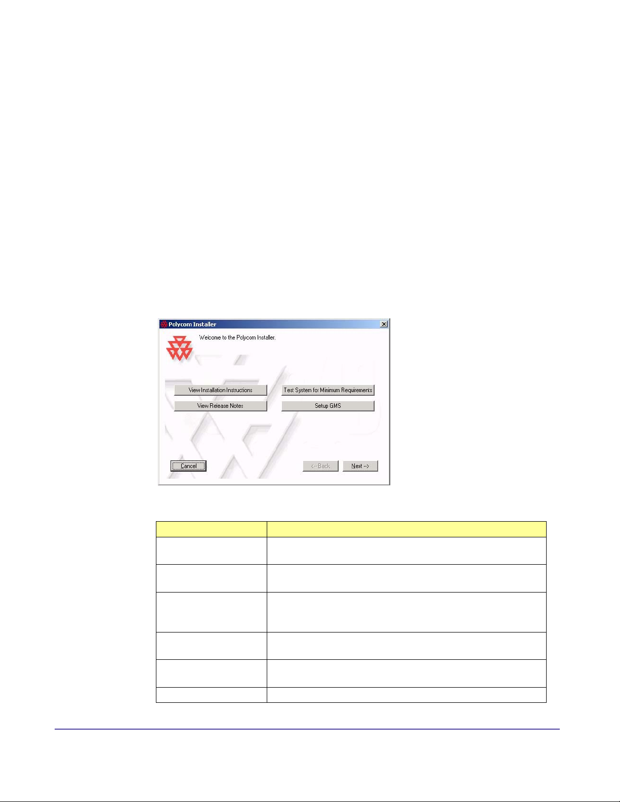
Figure 1.1 Polycom Installer > Home Page
The main window has the following buttons:
Button Name Description
View Installation
Instructions
View Release Notes Displays the Release Notes (requires Adobe Acrobat
Test for Minimum
Requirements
Setup GMS Begins installation. This performs all the pre-installation
Next Functions identically to the “Install Global Management
Cancel Exits the Polycom Installer.
Displays more detailed installation instructions.
Reader).
Performs tests to determine if your system meets
the minimum software requirements to install Global
Management System.
tests before launching the GMS setup utility.
System” button.
8Chapter 1 Getting StartedGlobal Management System User’s Guide
Page 14
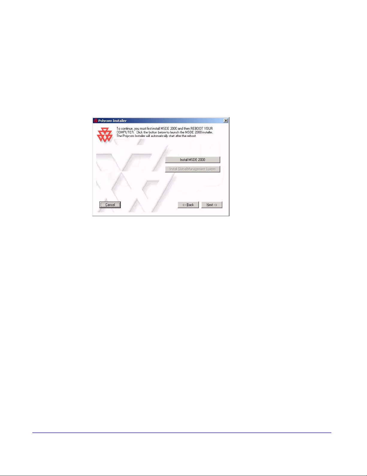
Installation Instructions
Installing the Polycom Datastore
The Polycom Datastore is a data repository for Global Management System. The Polycom
Datastore also requires MSDE as its database program. If an older version of MSDE is not
installed or found on this machine, Global Management System will prompt to install the
supported version located on the install CD.
Figure 1.2 Polycom Installer > MSDE Prompt
You can choose what directory you install MSDE into by browsing into the appropriate directory
when that dialog prompt appears. If a reboot is required, the Polycom Installer will automatically
be relaunched after the server reboots.
After the initial installation requirements have been met, the Global Management System
installer will inform the user that Polycom Datastore is about to be installed. Follow the onscreen
instructions which will guide you through the Polycom Datastore installation.
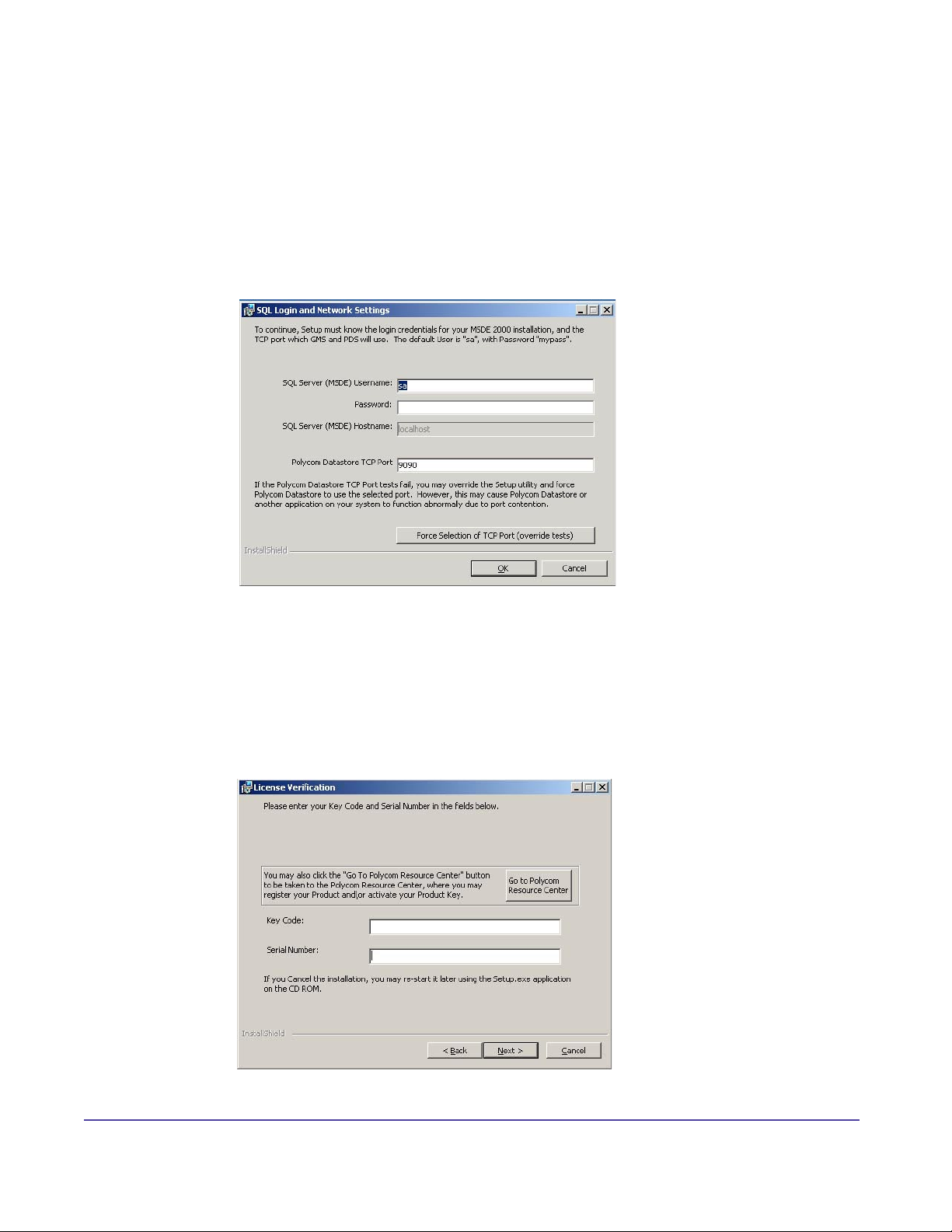
MSDE Login
Global Management System will detect and prompt for a username and password to the MSDE
database. If the login information is not known, Global Management System will not install. Enter
the login information for MSDE, the default username is “sa” and the password is “mypass”.
TCP port
The Polycom Datastore TCP port is the port used for communications between the Polycom
Datastore and Global Management System. The port number should not have conicts with
other applications using that port. The default port is 9090.
9Chapter 1 Getting StartedGlobal Management System User’s Guide
Page 15
Installation Instructions
You may specify a different port if the default port is already in use by another application. If you
are certain the selected port is free and yet the Port Test continues to fail, you may force the
Polycom Datastore to sue the selected port by clicking “Force Selection of TCP Port”. Be aware
that this may cause Global Management System or some other server application to function
abnormally.
Figure 1.3 Installation > MSDE Login
Licensing
The installation will require a serial number and a key code. The key code is the activation
number for this version of Global Management System. You can obtain a key code by
registering your license information at http://extranet.polycom.com and going to Product
Activation.
Figure 1.4 Installation > License Verication
10Chapter 1 Getting StartedGlobal Management System User’s Guide
Page 16
Installation Instructions
Installing Global Management System
You will be asked to respond to the following.
A. Accept End User License Agreement.
B. Enter Manager URL.
C. Choose Default Web Page
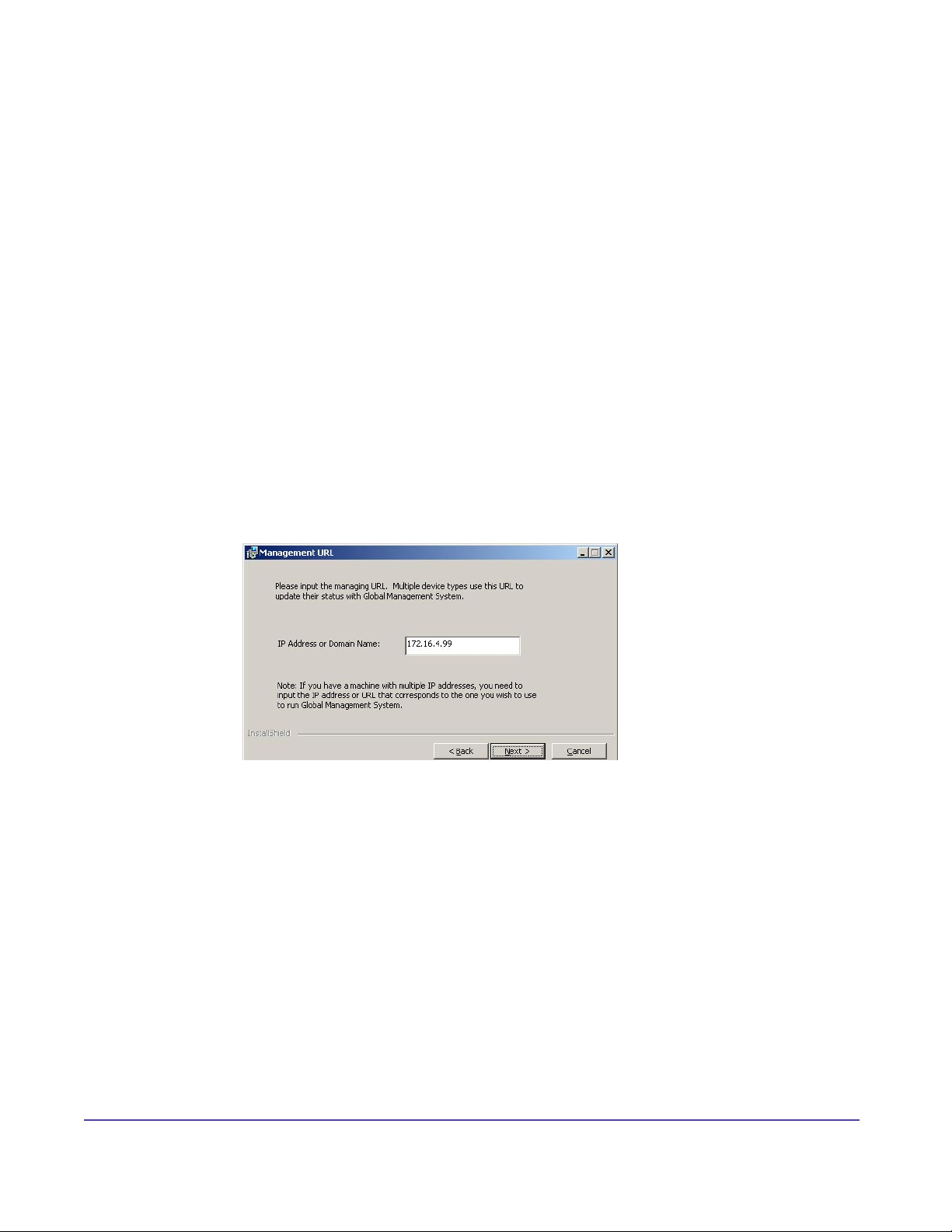
Manager URL
The Manager URL is what the ViewStations use to communicate with Global Management
System. In cases where the system has multiple IP addresses, this allows the selection of one
particular address for use with Global Management System. In most cases except for systems
with multiple IP addresses, the default shown should work.
In some applications, it is preferable to use a host name instead of an IP address. If this is the
case, enter the fully qualied domain name for the Manager URL For example, if your Global
Management System server host name is “GMSMain” and the domain name is “companyA.com”,
then “GMSMain.companyA.com” should be entered as the Manager URL for the installation.
Figure 1.5 Installation > Management URL
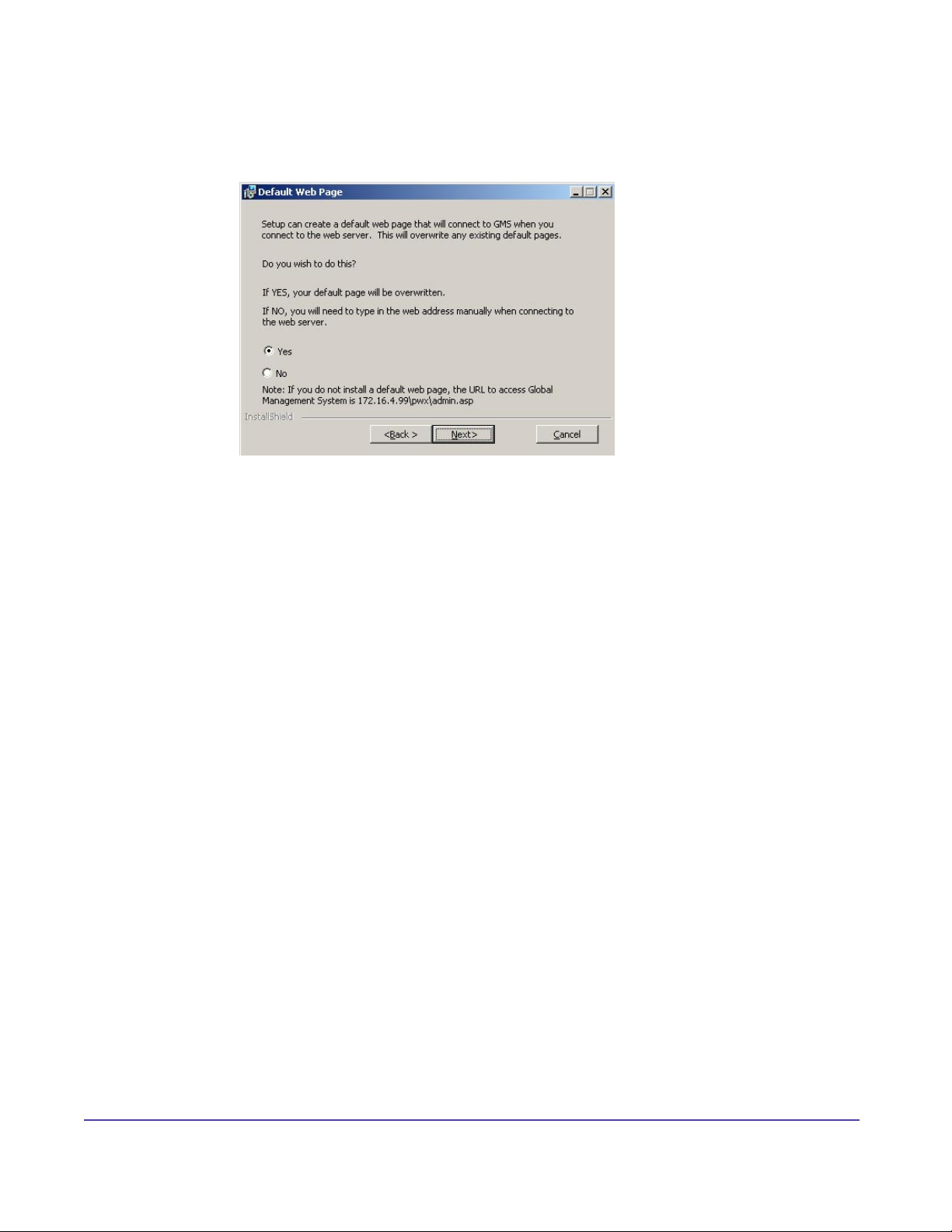
Default Web Page
If “Yes” is selected, setup will overwrite the default web page with a web page that points to the
Global Management System. When uninstalling, the original default web page will be restored.
If ‘no’ is selected, the original default web page is preserved but users connecting to the Global
Management System server will need to type in the complete web address. (E.g. by default, http:
//SystemIP/pwx/admin.asp, where SystemIP is the IP address or URL of the Global Management
System server).
11Chapter 1 Getting StartedGlobal Management System User’s Guide
Page 17
Installation Instructions
Figure 1.6 Installation > Default Web Page
Installation Type
Standard installation will install Global Management System on the default drive using the
following directory drive:”\Program les\[Polycom folder]”. Custom installation enables you to
choose a different drive or directory to install the program les to.
Upgrading from a previous version
Click on setup.exe and follow the onscreen instructions.
Licensing
Enter the key code provided to you in the email notication sent from Polycom regarding the
Global Management System release. If your email is inaccessible, you can look up your key
code information by going to Product Activation. If there is no information available, please
contact Technical Support.
12Chapter 1 Getting StartedGlobal Management System User’s Guide
Page 18

Licensing Information
Overview
Global Management System Licenses are based on the number of subscribed endpoints. Global
Management System is a software application that enables the user to enter as many license
keys needed to manage endpoints within a video communications network. Each of these
license keys will correspond to one of the following predened license packs enabling ‘n’ number
of devices: 1, 5, 25, 100, 500, or 3000 seats. These license packs will combine to form the
number of endpoints that can register with Global Management System.
Adding more Licenses
In order to increase the number of licenses that are currently supported, the user will have to
purchase a new license pack of 1, 5, 25, 100, 500 or 3000. This new license key can be added to
the current installation of Global Management System to increase the seat count appropriately.
Demo version
A fully functional demo version of Global Management System is only available for evaluation
purposes. Each demo version allows for 3 endpoints to be managed for 90 days. Each demo
must also have an demo code entered into Global Management System to be operable. To
obtain an demo code, please go to this website: http://extranet.polycom.com and go to the
Global Management System downloads area.
The 3-user demo version is not a registered license and cannot be coupled with registered
license keys. For example, if a 5-Pack license key was purchased, it cannot be coupled with the
3-user demo to generate 8 registered licenses.
13Chapter 1 Getting StartedGlobal Management System User’s Guide
Page 19
Licensing Information
Product Activation
Proper licensing is necessary to operate Global Management System. In order to activate Global
Management System, all license numbers must be activated and converted into a key code.
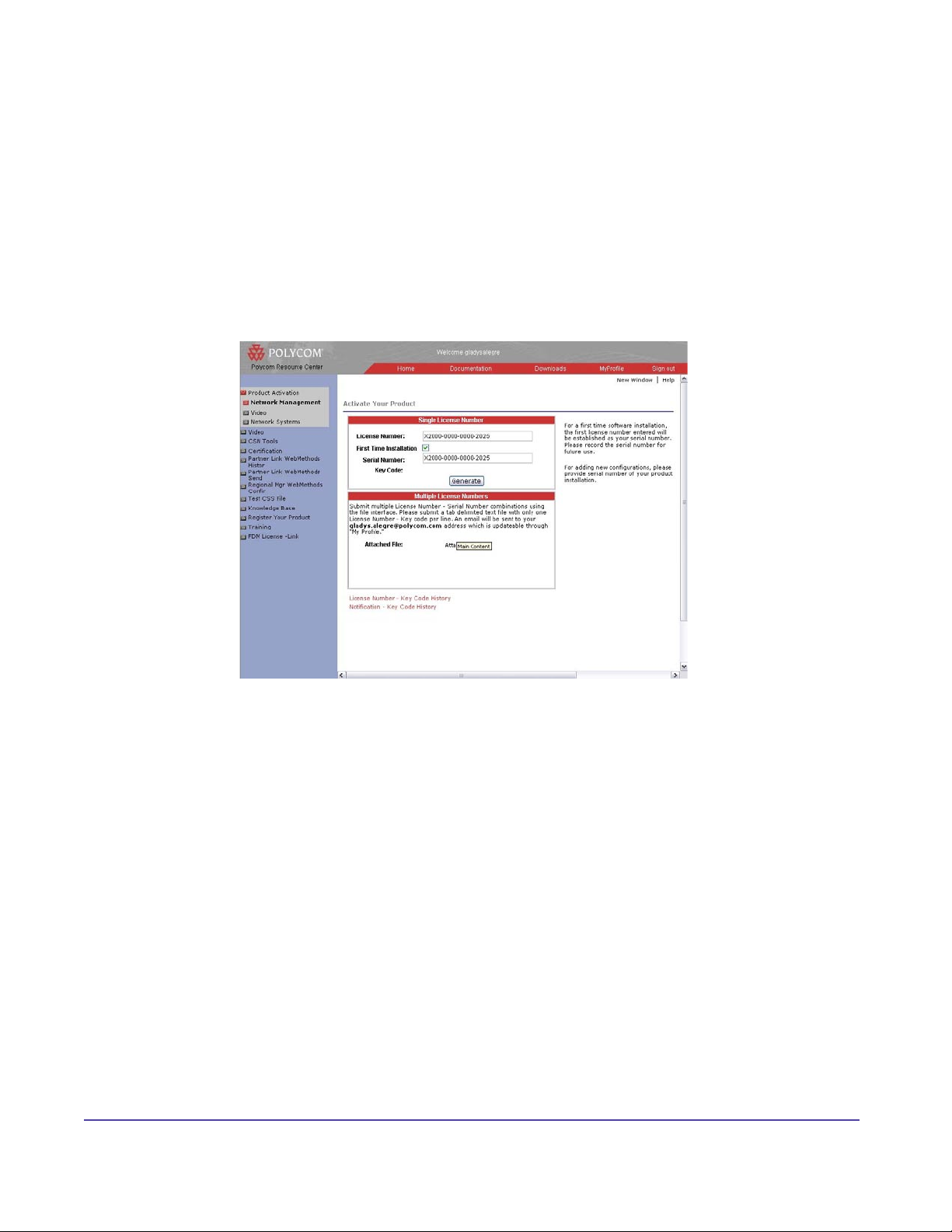
First time Installation
1. Launch a web browser and go to this URL, http://extranet.polycom.com and go to Product
Activation.
Figure 1.7 Polycom Resource Center > Product Activation page
2. Enter the license number in the “License Number eld” on the label of the packaging. A
“First Time Installation” check box will appear. When checked, the serial number will autopopulate in the “Serial Number” Field if this is the rst time registration.
3. Click Generate and copy as it appears the key code for installation. Record the serial
number and key code for future use.
** If additional licenses are required, install Global Management System rst with the
key code that was generated when the serial number was established. Then, follow the
instructions for Adding additional license seats.
Adding additional license seats
Adding License seats key codes will be referred to as Congurator keys in the historical key code
data in the Polycom Resource center Product Activation page. Congurator key codes cannot
be used to install Global Management System.
To add license seats, enter each license number and the serial number of the application into
the appropriate elds in the Product Activation page in the Polycom Resource center, this can be
found on the Conguration > License Authentication page of the Global Management System.
14Chapter 1 Getting StartedGlobal Management System User’s Guide
Page 20

Licensing Information
Click Generate after entering each license number. When applying the congurator key codes
into Global Management system, use the last key code generated because this will contain the
cumulative number of seats for this serial number.
Applying the key code in Global Management System
When adding additional licenses and no installation is involved, the key code can be applied
by logging into Global Management System and navigating to the Conguration > License
Authentication screen.
Upon entering the key, the information for the license capacity should reect the actual number
of seats registered.
Figure 1.8 Configuration > License Authentication
15Chapter 1 Getting StartedGlobal Management System User’s Guide
Page 21

Licensing Information
Premier Service
Global Management System comes with an initial 90-day warranty entitling the customer to
maintenance support including software updates (bug xes), as well as software upgrade (new
feature) releases. Bug Fixes may come in the form of a new revision of software or just a patch
release. Once the initial 90-day period is over, if the customer wishes to continue to receive
support, updates and new product releases, purchasing a maintenance contract is the most
economical solution. Customers should contact their Polycom Reseller or a Polycom Sales
representative for details.
Receiving Key Codes
If your installation is under maintenance, when there is a new release you will receive a
notication that contains the key code that will enable you to upgrade to the corresponding
release of Global Management System.
16Chapter 1 Getting StartedGlobal Management System User’s Guide
Page 22

Installation and Conguration Tips
Introduction
In order to achieve maximum performance and proper operation of Global Management System,
the server upon which it is installed must be congured correctly. The following guidelines aids
in conguring a Windows 2000 or 2003 server that can provide the best performance and avoid
compatibility or operational problems.
Hardware
The hardware platform hosts the server operating system and the Global Management System
must meet the minimum requirements specied in the User’s Manual, page 3. The system must
have a minimum of 128 megabytes of RAM, a Pentium III processor running at 650 MHz or
higher and at least 300 megabytes of free hard-drive space.
TIP: Make sure your server is up to the task
For best performance (and for supporting ViewStation networks of 50 systems or more), 256
megabytes of RAM or more is required for optimal performance. A processor running at 1 GHz
or greater is strongly recommended for best server response.
Operating System
Windows 2000 Server and Windows server 2003 are required to support Global Management
System. Global Management System is a server-based application and will not run on desktop
operating systems such as Windows 2000 Professional or Windows XP.
Server Conguration
Global Management System can be installed on a server that is part of an NT domain or as
a standalone server.
Network Conguration: Single Static IP Address
Conguring the server with a static IP address is highly recommended. If the server is congured
to obtain an IP address automatically, the IP address issued to it by the DHCP server will not
remain the same over a long period of time. If the IP address changes, endpoints congured to
send status updates will not be informed of the change.
Network Conguration: Dynamic Address
If your server uses DHCP and its address is likely to change, use a host name as opposed to
using IP addresses for the Manager URL. Enter the fully qualied domain name (i.e., host name
+ domain name) when the Manager URL is requested during the installation process.
TIP: Assign a domain-name to your server
Although not necessary, it is recommended that the server be congured with a domain-name
that is resolvable through DNS. Contact your IT department to have a domain-name assigned
to your server. When setting up Global Management System, specify this domain name as the
address that ViewStations will use to send status updates to.
17Chapter 1 Getting StartedGlobal Management System User’s Guide
Page 23

Installation and Conguration Tips
The server should not be congured with multiple IP addresses. If the machine is dedicated
to hosting Global Management System as is recommended, a single IP address is adequate.
Having multiple IP addresses will complicate the Global Management System conguration
process.
Service Pack Installation: Windows 2000 Service Pack 3
If you are running Windows 2000 Server, Windows 2000 SP3 is required. This service pack contains xes from Microsoft to key elements of the operating system that are necessary to insure
the proper operation of Global Management System.
No Service Packs are currently required for Windows Server 2003.
Firewall Port Conguration
Protocol Port Direction
HTTP 80 Bidirectional
FTP 21 Unidirectional to endpoint
For ViaVideo 3603 Bidirectional
For Global Directory 3601 Bidirectional
For Polycom Datastore Default 9090 Bidirectional
These ports must be open for information to go through the rewall. Global Management System
uses port 80 and 21 for endpoint management, port 3603 for ViaVideo and port 3601 for Global
Directory listing and retrieving.
Software
Internet Explorer 6
Internet Explorer 6.0 SP1 or later must be installed on the Global Management System server.
You can download Internet Explorer 6.0 SP1 directly from Microsoft by clicking the following link:
http://www.microsoft.com/windows/ie/download/default.htm.
TIP: Don’t congure a proxy server in Internet Explorer
After installing Internet Explorer on the server, do not enable any proxy server conguration or
automatic conguration detection even if your network normally requires it. In order for Global
Management System to communicate with endpoints correctly, it must have a direct connection
to the unit with no proxy server or rewall. Proxy server congurations in Internet Explorer will
affect all applications that use Internet session services.
To insure that Internet Explorer is correctly congured for Global Management System, open a
browser window and select Tools | Internet Options from the menu, select the Connections tab,
then click the LAN Settings button. Make sure that Automatically detect settings, Use automatic
18Chapter 1 Getting StartedGlobal Management System User’s Guide
Page 24

Installation and Conguration Tips
conguration script and Use a proxy server are not checked. If any of these settings is enabled,
uncheck it, click OK and reboot the server to insure that the new settings take effect.
Internet Information Services
Global Management System is a web-based application built using facilities provided by Microsoft Internet Information Services (IIS). If you are using Windows 2000, IIS should have been
installed by default. If you need to install Internet Information Services, you can through the
Add/Remove Program les icon on the Window 2000 Control Panel. IIS 5.0 is available on the
Windows 2000 CD.
IIS 6.0 is included on the Windows Server 2003 installation CD, but is not installed by default. To
install IIS 6.0 use the “Add or Remove” programs Control Panel. “Internet Information Server” is
found in the “Application Server” Component under the “Add\Remove Windows Components”
options.
TIP: Don’t change Internet Information Server settings unless it is necessary
Global Management System is designed to operate correctly using a standard installation of
Internet Information Services using the default options selected by the IIS setup program. Do not
change any web server conguration settings or security settings unless it is necessary. Always
test the web server conguration settings before implementation in a production environment.
TIP: Keep the machine in an IT operations facility
The Global Management System server should be located in a secure information services
facility rather than in an ofce or location where it could be inadvertently turned off, unplugged
or damaged. The Global Management System user-interface is web-based and can be access
using a browser from any desktop, therefore, once the server is setup and congured, there is
no reason to use it directly. Ideally, the server should be kept in a locking server rack to prevent
tampering or being turned off.
TIP: Use a UPS
An uninterruptible power-supply (UPS) is strongly recommended. In order for services such as
call-detail recording, Global Directory accessing, account validating and network status monitoring to work effectively, the server must be running at all times. Sudden power-loss to the server
will often result in hard-drive corruption.
19Chapter 1 Getting StartedGlobal Management System User’s Guide
Page 25
Logging on
Accessing the Global Management System Console
To access the Global Management System console user interface from the server or the client,
open Internet Explorer and enter the IP address or name of the server that hosts the Global
Management System services.
If the option to select a default web page was not selected, you will need to enter the full URL of
the Global Management System application:
To access from the server console
Launch Internet Explorer, type the following:
http://localhost/pwx/admin.asp
Where server-name is the name or IP address of the Global Management System server.
To access from the client
Launch Internet Explorer, type the following:
http://server-name/pwx/admin.asp
NOTE
If the server does not have a name, you can type in the IP address of the system
20Chapter 1 Getting StartedGlobal Management System User’s Guide
Page 26
Logging on
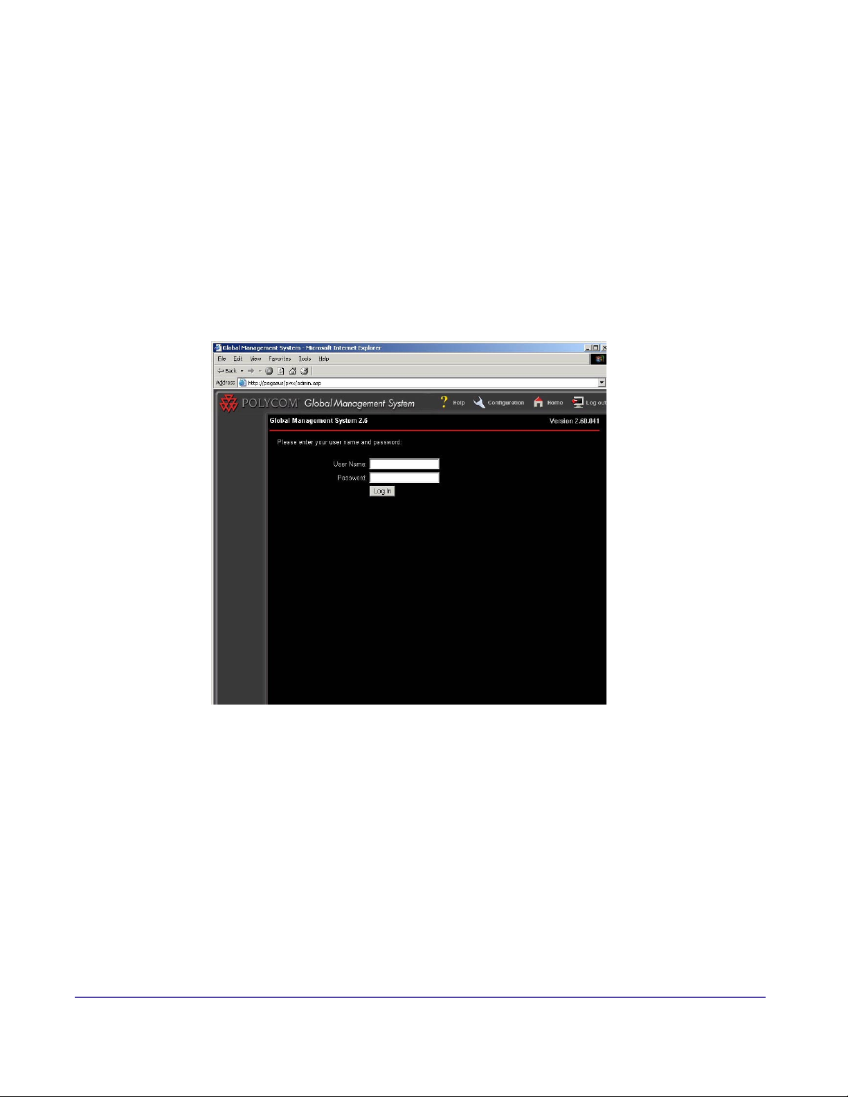
Logging on to Global Management System
User name: admin (This is the default user name.)
Password: blank as in no characters (Upon initial login, the system will immediately require a
change in the password to something containing characters.)
NOTE: The logon for Global Management System is not the same as the logon for the Polycom
Datastore.
Figure 1.9 Global Management System Login screen
To learn how to make changes to the user name and password, please refer to page 101.
21Chapter 1 Getting StartedGlobal Management System User’s Guide
Page 27
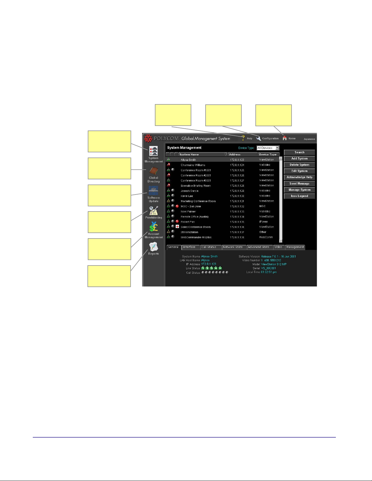
Product Overview
The program’s default page is the System Management page. The main navigation on the left
hand side of the screen provides easy access to all of the sections of Global Management
System.
Figure 1.10 Global Management System product overview
Monitor and
Manage
Centralized
Directory
Update
Endpoint
Software
Provision
Endpoint
proles
Access
Online Help
Set SNMP,
Remote Alert
Notication
Goes Back
to System
Management
Create Accounts
Call Detail
Record, Network
Status
Feature summary
System Management
Add, edit and delete systems from the Database.
Provides details of video endpoints, PathNavigator, WebCommander and Other Device status
Remote Management of Polycom video endpoints
Global Directory
Creates, edits, archives, imports and exports address books
LDAP and ILS supports replication of address entries for different Global Directory Servers
Automatic registering of video endpoints on the LAN into the Global Directory
Software Update
Polycom video endpoints can be updated immediately or at a scheduled time
Provides status of software updates and maintains a log for troubleshooting failed updates
22Chapter 1 Getting StartedGlobal Management System User’s Guide
Page 28
Product Overview
Feature summary continued
Provisioning
Push new conguration settings to a group of Polycom group video endpoints
Create separate proles tailored to different Polycom group video endpoints
Account Management
Set up accounts used to track video calls
Reports
Call Detail Record - Details information of ViewStation, V-Series, iPower, and ViaVideo video
calls
Network Status - Describes statistics of endpoint usage
Device Tracing - Diagnose endpoint issues by logging endpoint activity
System Conguration
Group Administration - Group Administration - Add, remove and modify groups and create group
permission levels
User Administration - Add, remove and modify users and permissions
Server Preferences - Congure defaults for Software Update, Provisioning, Email Remote Alerts
and Device specic behavior
Remote Alert Notication - Set criteria for email alerts and SNMP alerts
NOTE
SoundStation VTX 1000 features are limited to 1) phone database conguration, 2) software
update/upgrade scheduling and status. All other features listed herein which are related to
IP endpoint support do not apply to SoundStation VTX 1000 which is soft modem-enabled
circuit switched (analog) telephony device.
23Chapter 1 Getting StartedGlobal Management System User’s Guide
23Chapter 1 Getting StartedGlobal Management System User’s Guide
Page 29

Product Overview
The table below shows which Global Management System features support which devices.
Features ViewStation,
FX and EX,
V-Series
System
Management
Global
Directory
Software
Update
Provisioning X No X No No No
Account
Management
Reports X X X No X X
Remote Alert
Notication
X X X X X X
X X X No No No
X No X No No No
X No No No No No
X X X No X X
ViaVideo iPower VTX 1000 MGC
PathNavigator
WebCommander
Other
Device
24Chapter 1 Getting StartedGlobal Management System User’s Guide
Page 30
2
System Management
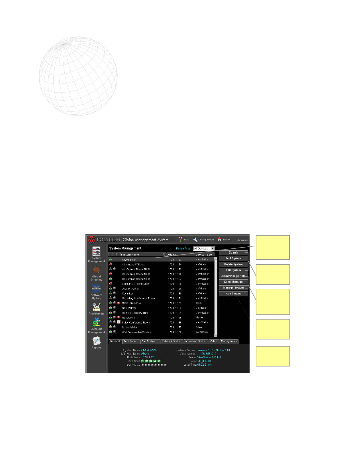
System Management Overview
The System Management window provides a list of Polycom endpoints and third party devices
connected to the network. Management of your Video Communication network begins here.
Global Management System enables the monitoring and management of video endpoints. Also,
monitoring capabilities have been extended to include other Polycom management tools such as
the MGC, WebCommander, PathNavigator and third party endpoints.
Figure 2.1 System Management
Device List
View Status
of Systems
Modify
System List
Send
Message
and Remote
Management
Icon Legend
Describes
icons used
System
Details
shown here
25Chapter 2 System ManagementGlobal Management System User’s Guide
Page 31
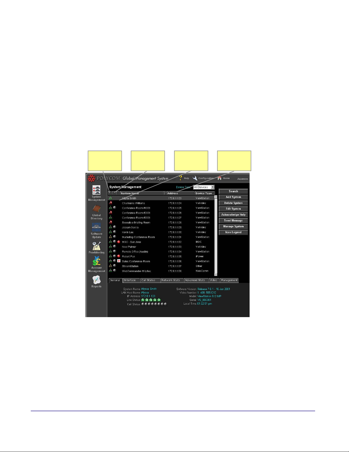
System Management Console
Overview
• The System status of listed endpoints can be seen at a glance
• Search for, add and delete systems to/from your network
• Remotely administer a system using the Manage System button
• Send Message button allows for communication between the System Administrator and
the ViewStation, ViaVideo or iPower user
• More detailed information for a specic device is summarized in the System Information
window, which is right below the system list
Figure 2.2 System Management
Status
Endpoint
Status
Errors and
Warnings
Sort Feature Connectivity
The system list defaults to an alphabetical listing of the device names. Since Global Management
System can manage different devices, a pull down menu allows the display of the list by device
type or all devices.
You can modify the systems list, send messages or manage video endpoints by using the
Utility buttons on the right. Below the system list, you can view status information specic to the
highlighted device in the system list, including call status, line status and statistics on the video
call connection.
26Chapter 2 System ManagementGlobal Management System User’s Guide
Page 32

System Management Console
The table below details what the icons represent for each column in the System Management
Page.
NOTE
SoundStation VTX 1000 features supported below include Connectivity Status, System Name,
Device Type and Address, with the address indicating the phone number (or extension) of the
system in question, not the IP address. Connectivity Status indicates that the SoundStation
VTX 1000 in question has been congured for remote software support, but it not an indication
of real-time connectivity status.
Column header Description
Global Management
System Connectivity
Status
Green network icon - Indicates that Global Management
System can successfully communicate with the system.
Green network icon with log - Global Management system
is logging system information.
Red network icon- The server is unable to communicate
with a system. This may indicate:
• System power off, malfunctioning
• System network cable disconnected
• Network switch or hub malfunctioning
Yellow network icon - Indicates that Global Management
System is able to query the system, but is unable to
receive status updates. The following are prioritized in the
order you should check to diagnose the problem.
• Endpoint password required
• Software update required for endpoints
• Manager URL not set in the video endpoint
Endpoint Status The video endpoint is not in a call.
A video endpoint is in a call. When a video endpoint is
initiating a call, this column will show the change in ball
state starting with a blue sphere, to a yellow sphere,
then to an orange sphere progressing to the fully
connected call, a green sphere. These spheres represent
the progress of connecting the conference call.
A video endpoint user in a conference room can send
a message to the system administrator by requesting
help. When the server receives a help-request alert, a
red cross will appear in this column until help-request is
acknowledged.
27Chapter 2 System ManagementGlobal Management System User’s Guide
Page 33

System Management Console
Column header Description
Errors and Warnings The number on the icon indicates the number of errors or
warnings occurring with the system. Errors and warnings
can occur with a system concurrently. For this case, the
number of errors and warnings occurring with a system
will appear on the combination icon. This information will
be detailed on the Alerts Tab. Errors are generally critical
to the operation of the unit. Warnings indicate that the
user may be inconvenienced during the operation of the
unit.
Error Types
ISDN Line error
The video endpoint fails to detect signal from ANY of the
ISDN lines. For example, if an endpoint with three ISDN
lines has 2 lines working but 1 line is down, then this unit
gets a red arrow.
Lost Gatekeeper
The video endpoint cannot nd the gatekeeper that it
normally registers with. The gatekeeper might be in an
ofine state.
Microphone unplugged
The iPower is detected to have unplugged microphone
from the main unit of the video endpoint.
Camera unplugged
The iPower is detected to have an unplugged camera
from the main unit of the video endpoint.
Internal System error
The iPower is detected to have an internal system error.
Cannot nd server
This pertains to Web Commander and Other Device.
Global Management System is detecting HTTP errors
coded either 4XX or 5XX from the device’s web server.
Internal System Error
The iPower system has experienced an unexpected
malfunction. Restart the system. If the problem persists,
contact Polycom Technical Support.
28Chapter 2 System ManagementGlobal Management System User’s Guide
Page 34

System Management Console
Column header Description
Errors and Warnings
cont.
System Name Name of endpoint
Address Name IP address of endpoint
Device Type Identies device type
Warnings
Low Battery
The battery in the video endpoint remote control is
running low.
Lost Directory Server
The iPower cannot display the Global Directory. The
Directory server may be ofine.
Web Server Redirect
Redirect response string (HTTP 3XX) returned from an
Other Device server.
iPower User Interface not running
The iPower user interface is not operating
29Chapter 2 System ManagementGlobal Management System User’s Guide
Page 35

Modifying the System List
The utility buttons on the right hand side of the screen allow you to change the information in the
system list.
Search Search for systems on the network which have not
Add System Allows you to add a system to the database to be
Delete System Removes a system from the database
Edit System Informs Global Management System a system IP
Searching for Systems
One way to add a system is to search for units of a certain device type. The search function
allows you to nd video endpoints connected to the network but not yet managed by the
program.
been added to the database. After performing a
search, system can be added from the query results
managed by Global Management System
address and password change or enables device
tracing for a system.
1. To search for addresses, click on Search. The search dialog box appears.
2. ViewStation, ViewStation FX and EX, V-Series, ViaVideo and iPower are default to check.
If desired, uncheck the device type that does not require search.
3. Enter the Start and End IP addresses. The End IP eld will auto complete the range that
you entered in the Start IP eld.
4. Click on OK to start search. All of the systems found on that subnet not yet managed by
Global Management System will be listed.
5. The results will return with all systems auto-selected. Deselect the systems you do not
wish to Manage, then click on Manage Selected Systems.
30Chapter 2 System ManagementGlobal Management System User’s Guide
Page 36

Modifying the System List
Adding a System
Use this feature to add Polycom video endpoints, SoundStation VTX 1000 conference phone
endpoints, and management programs or other (third party) device to the Global Management
System database.
Adding a ViewStation
1. Click on Add System. A new window will appear.
2. Choose the device type you want to add with the pull down menu.
3. Enter the IP address or LAN host name of the system and the password if the system has
a password set.
4. Click on OK. The System Management window will refresh and the device name and
address will appear.
NOTE
A ViewStation cannot be added to the database through the “Add System” function without
specifying that password in the password eld if it has an administration password set on it .
NOTE
The characters used for the ViewStation system name must conform to the character set
found in the ViewStation soft keypad.
Adding a ViewStation FX and EX.
Follow the same steps for adding a ViewStation.
Adding a V-Series
Follow the same steps for adding a ViewStation.
Adding a ViaVideo
Follow the same steps as for adding a ViewStation.
Adding an iPower
Follow the same steps as for adding a ViewStation. If the admin password is set on the iPower
system, it needs to be entered here. To learn how to set the iPower system password, refer to
page 115.
Adding a VTX 1000
Follow the same steps as for adding a ViewStation. Enter each endpoints’ phone number (versus
IP address) with requisite prexing and dialing codes, just as if a phone call (versus modem call)
were being placed to the endpoint.
31Chapter 2 System ManagementGlobal Management System User’s Guide
Page 37

Modifying the System List
Adding a System
Adding a PathNavigator or a WebCommander
1. Click on Add System. A new window will appear.
2. Choose PathNavigator or Web Commander from the pull down menu.
3. Enter the IP address or LAN host name of the system and the name you would like to
identify this system by.
4. Click on OK. The System Management window will refresh and the device name and
address will appear.
Adding an MGC
1. Click on Add System. A new window will appear.
2. Choose MGC from the pull down menu.
3. Enter the IP address or LAN host name of the system and the name you would like to
identify this system by.
4. Enter the Login and password for the MGC.
5. Enter the computer name which is the name of the computer on which GMS is running,
and is displayed in the MGC Manager UI as part of the “Connection” information.
4. Click on OK. The System Management window will refresh and the device name and
address will appear.
NOTE
An MGC-25 is not manageable by Global Management System.
Adding an Other Device (Third Party)
Third party devices can be added to Global Management System for monitoring if it has a
web-based interface.
1. Click on Add System. A new window will appear.
2. Choose the device type “Other” from the pull down menu.
Enter the following information:
• IP Address or LAN Host Name
• Port: Port on the device used to access the device’s management interface.
• Name: The name that you would like to call the system
• File (Optional): Web management entry le. If the device’s web server has the
appropriate default website; no le is necessary
Management URL: This is a read only eld which displays the specied URL which Global
Management uses to access the web interface.
3. Click on OK. The System Management window will refresh and the device name and
address will appear.
32Chapter 2 System ManagementGlobal Management System User’s Guide
Page 38

Modifying the System List
Editing a System
Normally, the Global Management System automatically detects IP address changes for
ViewStations and ViaVideos and updates its database with the new information. However, certain
circumstances can arise where the server and the endpoints are unable to communicate with
one another and this automatic detection is not possible. This is especially true in the case of
IP address changes for WebCommander and third party endpoints. In this case, the IP address
stored in the database must be updated manually.
Device Tracing allows for all video endpoint actions to be traced and recorded in a Device trace
log. Device tracing can be enable here in the Edit System window or in the Reports > Device
Tracing page in Global Management System.
For SoundStation VTX 1000, tracking endpoints and correct/current phone numbers is a manual
process. It is recommended that once the SoundStation VTX 1000 endpoints are congured, the
Global Management System administrator set a policy that he/she be contacted in the event that
SoundStation VTX conference phones are relocated. This will assure that the Global Management
System has the correct phone number for software updates and upgrades.
Edit System
1. Select an Endpoint and click on Edit System. A dialog box will appear.
2. Enter the relevant information for the system or enable device tracing.
3. Click on OK.
Password
Global Management System can manage a Polycom group video endpoint when the password set
in Global Management System matches the password that is manually set on the endpoint. For
security reasons, the administration password for an endpoint can be set only from the endpoint.
If the password is changed manually from the endpoint, you must update Global Management
System with the new password otherwise the system can longer be managed. By default,
endpoints do not have an administration password set.
As with the endpoint, the administration password for an endpoint can only be set from the
endpoint unit. Any password changes for any given unit must also be updated in Global
Management System. To learn how to change the password for the endpoint, please refer to
page 115.
NOTE
Entering a password here does not mean that the administration password for a ViewStation
has been set. If an administration password is needed, then it must be set at the unit.
33Chapter 2 System ManagementGlobal Management System User’s Guide
Page 39

Modifying the System List
Deleting a System
When a system is deleted from the Global Management System database, it is still connected
to the network but is no longer being managed via Global Management System, (except
SoundStation VTX 1000).
1. Select the device you wish to remove from the list.
2. Click on Delete System. The Delete System dialog box appears which states, “Are you
sure?”
3. Click on Yes to conrm.
34Chapter 2 System ManagementGlobal Management System User’s Guide
Page 40

Other System Management Functions
Acknowledge Help Clears help icon and sends a message to the user
Send Message Sends a message to the ViewStation or ViaVideo
Manage System Launches management web page for the selected device
Below is a table showing which buttons support which device.
Device Type Acknowledge
Help
ViewStation and
FX/EX
V-Series X X X
ViaVideo X X X
iPower X X X
iPower No No No
MGC No No X
PathNavigator No No X
WebCommander No No X
Third Party Device No No X
X X X
Send
Message
Manage
System
Acknowledge Help
While operating a video endpoint, a user might request help from the system administrator.
When help is requested, a red cross will appear next to the user’s device in the System List to
signal the administrator.
To clear the help request indicator and send a message:
1. Select the endpoint signaling help.
2. Click on Acknowledge Help. A window will pop up with information sent by the user and
a space to enter a message to send back to the user.
3. Click on Send.
Sending a Message
Click on this button to send a text message that will appear on the monitor for the selected
Polycom endpoint for a brief period. The text message can be up to 100 characters in length.
This feature can be used to discreetly notify the endpoint user that their scheduled conference
time has expired.
To send a message:
1. Select the video endpoint you would like to send a message to.
2. Click on Send Message. A pop up window will appear.
3. Type the message you wish to send and click on OK. The message will appear on the
device’s monitor for a brief period of time.
NOTE
If the endpoint is in a call, the far site will not see the message.
35Chapter 2 System ManagementGlobal Management System User’s Guide
Page 41

Other System Management Functions
Manage System
Polycom Video Endpoints
Polycom video endpoints have an embedded web server that allows you to manage the unit
from a remote PC on the same local area network. Any endpoint can be managed by calling up
it’s IP address in any web browser. To remotely manage a system through Global Management
System, select the system of interest in the system list and then click on the Manage System
button. A new browser window will appear displaying the endpoint’s web page.
Remote Management allows you to:
• Run diagnostic tests on a system
• Change the system conguration for the endpoint
• Place a call from the system for line status verication
Certain video endpoint models require specic setups in order to access the web interface. See
below.
ViaVideo
For versions below 5.0:
To manage ViaVideo, the “Web Access Password” must be set through ViaVideo. If the “Web
Access Password” is not congured, Global Management System cannot access the web
interface of ViaVideo.
To set the web access password from the ViaVideo interface, go to:
System Information > Setup > Global Services > Global Management
Enter the “Web Access Password”.
For 5.0 and above
To set the web access password from the ViaVideo interface, go to:
Setup > Web/GMS >
Enter the “Admin Password”.
iPower
iPower like the ViewStation also has an embedded web server that allows remote administration.
Manage System launches iPower WebRemote. WebRemote lets you make calls, congure the
system, diagnose operating problems, and monitor system performance from a web browser
running on a remote PC. In order to use WebRemote, it must be enabled on the system.
To learn how to enable WebRemote, refer to page 115.
36Chapter 2 System ManagementGlobal Management System User’s Guide
Page 42

Other System Management Functions
IPower cont.
After launching WebRemote, the password has to be manually entered. This is the administrator
password on the iPower system. If you are already logged in to a Windows domain account that
has administrator privileges on the iPower system, then you are automatically authenticated
when launching WebRemote. Therefore, a password is not required.
MGC
When a MGC is selected from the System List and the Manage System button is clicked, you
will be asked to download an object that is used to detect whether MGC Manager is located on
your machine and where that location is. If you decline to download this object, then Global
Management System cannot launch MGC Manager, if installed on this client, when the Manage
System button is clicked for a specic MGC. When this object is installed, clicking on the
Manage Button will result in either launching MGC Manager or informing you that the MGC
Manager is not installed on this client machine.
Polycom Management Applications – WebCommander and PathNavigator
When the application is selected and Manage System is clicked, the application’s web
management page is displayed in a separate browser window.
Other Device
When a third party device is selected, the website that opens is the URL specied when this
device was added to Global Management System. If the URL is incorrect, the information for the
selected device can be corrected by using the “Edit System” Feature.
37Chapter 2 System ManagementGlobal Management System User’s Guide
Page 43

System Information Window
This window contains information specic to the device selected in the System list. Below is a
screenshot of System Information tabs for a ViewStation.
Figure 2.3 System Management Tabs
Detailed information regarding the tabs for each device is found in the appendix on page 118.
General With the exception of the General Tab, the descriptions below pertain
to the video endpoints.
Displays general system information for video endpoints, server status
for WebCommander and response strings for Other Device
Interface Reveals the network congurations for the selected video endpoints
Call Status Detailed call status information
Network Stats Describes the video and audio protocols used
Advanced Stats Displays audio and video transmission rates
Video Shows video sent and received by the selected ViewStation
QoS Displays the components that allows the differentiation and
preferential treatment of network trafc for iPowers
Details Displays detailed information on video and audio conguration for
ViaVideo
Summary Displays summary information on endpoint and bandwidth statistics in
PathNavigator
Management Displays the URL of the different servers that manage the selected
video endpoints
Alerts Lists errors and/or warnings that are occurring with the selected video
endpoints
38Chapter 2 System ManagementGlobal Management System User’s Guide
Page 44

3
Global Directory
The Global Directory allows you to manage an enterprise wide address book server that can
support ISDN and IP dialing.
With automatic video endpoint registration into the Global Directory, dialing information, country
codes and dialing rules are automatically captured and updated. So calling anywhere in the
world will be as simple as using the speed dial function on your telephone.
The replication of Global Directory entries uses LDAP (lightweight directory access protocol)
and ILS (internet locator server) support. The added benet from LDAP and ILS support is the
consolidation of Global Directory entries from multiple networked Global Management System
servers. For more detailed information about this feature refer to page 53.
39Chapter 3 Global DirectoryGlobal Management System User’s Guide
Page 45

Global Directory Console
Address Book Pull Down Menu
The Address Book Menu lists the Address Books created in Global Management System or
imported address books from other servers. The default address book is titled “MAIN” unless an
administrator has modied its name. Other address books can be viewed by using the pull down
menu.
Figure 3.1 Global Directory
Alphabetical
list of systems
System Type
ViewStation or
ViaVideo
System’s IP
address and
ISDN number
Pull down
menu for
Address Books
Modify static
and dynamic
addresses
Create, edit
address
books
Import
and export
addresses
Set LDAP
and ILS
support
Address window
The Address window lists the addresses for the selected address book. These entries include
static, dynamic and replicated entries. Static entries are addresses that have been manually
added to the database. Dynamic entries are endpoint entries that auto-register with Global
Management System. Replicated entries are addresses that were replicated from another Global
Management System server through ILS or LDAP replication. More detailed information on these
three types of entries is provided on page 43.
• The red booklet is an entry that has been dynamically added to the system.
• Devices with a white booklet are entries that have been added to the system manually.
• A blue booklet indicates that these entries are replicated entries from another Directory
servers.
All of the information that is pertinent for calling by video is listed on this screen. The name
and more importantly, the IP address or ISDN number is also listed. The right hand side of this
window contains the utility buttons for address book modication and management, importing
and exporting the Global Directory and for server congurations.
40Chapter 3 Global DirectoryGlobal Management System User’s Guide
Page 46

Global Directory Console
Multiple Address Books
Multiple address books can be stored in the Global Directory for different departments, countries,
buildings, etc.
The accessibility of address books can be congured so to limit access of certain address books
by a video user. The system administrator can restrict access to certain address books. For
example, the CEO’s address book may have restricted access. Therefore all video endpoints will
not have access to the addresses in the CEO’s address book. Setting restrictions on address
books are made when editing the address of an automatically registered video endpoint. Refer to
Editing an Address in the Modifying Address section to learn how to set these restrictions.
NOTE
The ViewStation’s local address book can be remotely managed with the Address Book
Utility found in the GMS common directory.
41Chapter 3 Global DirectoryGlobal Management System User’s Guide
Page 47

Modifying the Address Book
New Address Books
Upon installation of the program, the Global Directory will automatically contain a default address
book that is accessible by all registered Polycom video endpoints. As long as a video endpoint is
congured with the server’s IP address it will dynamically register with the Global Directory and
appear in the default or main address book. Hence, the Global Directory will contain addresses
of video endpoints pointing to that server.
The Address Book utility is described below:
New Address Book Create a new address book
Edit Address Book Edit the name or description of the address book
Delete Address Book Delete the address book form the pull-down menu
Creating an address book
1. Click on the New Address Book button. A new screen will appear.
2. Enter the new address book’s name and description.
3. Click on OK. The new address book will appear in the pull down menu.
Editing an address book
1. Select the address book from the pull down menu.
2. Click on Edit Address Book. A pop up window will appear.
3. Enter the necessary information to correct the entry.
4. Click on OK.
Deleting an address book
1. Select the address book from the pull down menu.
2. Click on Delete Address book. The Address book entry will automatically be removed
from the list.
NOTE
You cannot delete the default address book
42Chapter 3 Global DirectoryGlobal Management System User’s Guide
Page 48

Modifying Addresses in the Global Directory
Modifying addresses in the Global Directory works differently with dynamic entries, static entries
and replicated entries. Polycom video endpoints that automatically register their addresses into
the Global Directory are dynamic entries. Static entries are addresses that are manually entered
into the Global Directory.
Dynamic entries
Dynamic entries are Polycom video endpoint addresses that register automatically with the
Global Directory. Polycom video endpoints register with the server every ten minutes. So
depending on the state of the endpoint, dynamic entries will appear or disappear from the
endpoint’s view of the Global Directory. A dynamic entry for an endpoint can occur only if the
endpoint is congured to report to the server. If the server’s IP address is not entered in the
appropriate eld when setting up the endpoint, auto registration will not occur.
The information corresponding with a dynamic entry is supplied by the endpoint conguration.
You cannot delete dynamic entries but the endpoint will reappear unless it is permanently
removed by unregistering the endpoint.
Static entries
A static address is a record that is manually entered into the Global Directory. Static addresses
are for video endpoints that cannot register with the server. Devices not located on the LAN
and require manual entry can be entered into the Global Directory through the static entry
mechanism. Static entries will remain in the Global Directory until it is removed.
Replicated entries
Replicated entries, designated with by a blue booklet, are video endpoint entries that have been
replicated through Lightweight Directory Access Protocol (LDAP) or Internet Locator Server
(ILS). When the replication of different Global Management System directories occur, auto
registered video endpoints and manually entered systems contained in the default address
books are replicated to and from each server. As a result, entries from Directory A’s default
address book will appear in Directory B’s default address book and vice versa. Note that entries
contained in address books other than the designated default will not be replicated.
Although you can select a replicated entry in the Global Directory and can click on Edit Address,
these entries cannot be edited. However, the specics of a replicated system are detailed when
Edit Address is performed.
Global Directory will also permit you to delete a replicated entry. However, deleting a replicated
entry is useless because the deleted replicated entry will reappear during the next replication
cycle.
43Chapter 3 Global DirectoryGlobal Management System User’s Guide
Page 49

Modifying Addresses in the Global Directory
As the administrator, there are three functions that are allowed in modifying Global Directory
entries:
New Address Creates a static entry in the Global Directory
Edit a static address Edit the contact information
Edit a dynamic address Change the list and view settings for the video
endpoint entry
Delete Address Deletes an entry
New Addresses
Creating a dynamic entry
In order for Polycom video endpoints to register with the Global Directory you must congure the
video endpoint to report to this Global Directory server. To learn how to do this, refer to page 59
- 62. Once the video endpoints are congured, the endpoints should register with the Global
Directory after being powered off and then back on.
Creating a static entry
Unlike dynamic Global Directory registration, the information entered here is “static”. If changes
are made to the system such as the acquisition of a new ISDN number or IP address, the user
must edit the information using the “Edit Address” function otherwise the information in the
Global Directory will be outdated.
1. Click on the New Address button. A pop up screen will appear with entry elds requiring
Name and Protocol.
2. Choose the type of entry by marking either the IP or ISDN checkbox.
3. Fill out the Name.
4. Fill out the appropriate information. The following page provides more information on the
items displayed in the New Address window.
5. Once the appropriate information is lled out, click on OK.
44Chapter 3 Global DirectoryGlobal Management System User’s Guide
Page 50

Modifying Addresses in the Global Directory
New Addresses
Figure 3.2 Global Directory > New Address
For IP
IP Address: IP address of video unit
E.164: H.323 alias that this unit can be identied by as a dial string.
Rate: The maximum speed which this unit can be called at.
For ISDN
ISDN Country Code: Country code where unit resides
ISDN Area Code: Area or City code where unit resides
ISDN Number A: ISDN Number of unit
ISDN Number B: If this unit has a 2x64 ISDN line conguration, the second ISDN number.
ISDN Extension: Dialed Extension number, which comes after Gateway number in a dial
string
Rate: Maximum speed which this unit can be called at.
45Chapter 3 Global DirectoryGlobal Management System User’s Guide
Page 51

Modifying Addresses in the Global Directory
New Addresses
Determining video call rate for ISDN entries
Entering the call rate information when creating a Static entries is relevant for non-Polycom
endpoint entries. However, you can enter the call rate for Polycom endpoints that cannot auto
register with the Global Directory.
For ISDN, the model of the video endpoint determines the rate and the maximum number of
ISDN lines the endpoint is equipped with.
Determining video call rate for IP entries
For IP calls, like ISDN, the model of the video endpoint determines the call rate. There are many
dependencies that affect the call rate of a video endpoint, which include type of model (i.e.,
ViewStation 128 can only make a 128 Kbps call), bandwidth capacity on the LAN and maximum
upload and download speed through your ISP provider. The table below lists the maximum rate
each family model can call at.
Endpoint Model Maximum Rate
ViewStation FX 1920 Kbps
ViewStation and EX 768 Kbps
ViewStation SP 384 Kbps
iPower 4000 Kbps
V-Series 512 Kbps ISDN/ 2000 Kbps IP
Global Management System User’s Guide
46Chapter 3 Global Directory
Page 52

Modifying Addresses in the Global Directory
Editing Addresses
Editing a dynamic entry
When a dynamic entry is selected, there is no option to edit the contact information. The Edit
Address feature functions differently for dynamic entries: the administrator can select which
address book a video endpoint will appear in. Also, the administrator can set the address book
permissions for a video endpoint.
Selecting which address book the endpoint will appear in
1. Highlight the preferred video endpoint in the Address window.
2. Click on Edit Address.
3. In the right column, under the section View, contains a list of address books from the
Global Directory. Click on the address books that this endpoint will have access to.
4. Click on Update.
Once the record is updated, the video endpoint will appear in the selected address books.
Results can be viewed by selecting an address book from the pull down menu. The video
endpoint entry will only appear in the address book(s) chosen.
To set permission access for viewing Global Directory entries from address books other
than the default address book
1. Select the video endpoint in the Address window.
2. Click on Edit.
3. The right column, under the section View, contains a list of address books from the Global
Directory. Click on the address books that the video endpoint will have access to.
4. Click on Update.
Once the record has been updated, the video endpoint can only access the selected Address
books. The addresses that appear in the selected address book will also show up in the video
endpoint’s Global Address book.
Global Management System User’s Guide
47Chapter 3 Global Directory
Page 53

Modifying Addresses in the Global Directory
Editing Addresses
Editing a static entry
You can only edit the contact information. Listing a static entry in multiple address books works
differently than dynamic address books. This address will only appear in the address book that
it was created in. In order for this address to be listed in multiple address books, it has to be
entered into each address book.
1. Select the video endpoint of interest
2. Click on Edit Address.
3. Correct the information and click on Update.
Global Management System User’s Guide
48Chapter 3 Global Directory
Page 54

Modifying Addresses in the Global Directory
Deleting an Address
Dynamic entries can be deleted but if the endpoint is still online, it will re-register within 10
minutes. If the endpoint is ofine, then the entry will remain deleted until the endpoint comes
back online. The Global Directory will allow you to permanently remove static entries. Since
static addresses are manually added, these addresses will remain in the Global Directory until
the entry is removed.
Deleting a Dynamic entry
For Polycom endpoints
If you want to permanently delete a Polycom endpoint from the Global Directory, delete the IP
address of the server from the following the Global Directory Services page.
Deleting a static entry
Highlight Address and click on Delete Address. The address will automatically be removed from
the list.
Global Management System User’s Guide
49Chapter 3 Global Directory
Page 55

Importing and Exporting the Global Directory
Information on Importing the Directory
Click on this button to import a comma-delimited (.csv) address book exported from another
Global Directory. Use this feature to share address book information between sites that cannot
register with the same Global Directory server. For example, a satellite ofce without a full-time
Internet connection might want to periodically import address books from the corporate server.
This allows a video endpoint at a remote ofce to have dialing information of other systems
within that organization. These imported addresses will be normalized with GlobalDial for the
location of the remote sales ofce.
Import Imports a .csv le into the Global Directory
Export Exports a .csv le from the Global Directory
Importing an Address book
1. Click on the Import button. A new dialog box will appear.
2. Browse to the le location on client machine.
3. Click on check box import entries as static addresses if importing addresses that will not
register with the Global Directory.
4. Click on check box import entries as static if importing addresses that will not register with
the Global Directory.
5. Click on Import data.
NOTE
Keep Import entries as Static Addresses as deselected when importing an address directory
containing endpoints that will register with the Global Directory.
This will prevent the Global Directory, you are importing to, from removing dynamic entries
that register with the Global Directory that you are exporting from. If this imported directory
contains video endpoints that report to another Global Directory server, these endpoint
entries cannot be dynamic entries to this Global Directory.
By leaving that check box deselected, the Global Directory will remove the imported dynamic
entries that do not register with Global Directory within 35 minutes. Static addresses will not
be removed from the Global Directory unless a user removes it manually.
NOTE
If “Do not overwrite existing static address entries” box remains unchecked, static address
entries with the same name and protocol type will be modied with the import address
information. If there is no existing entry with the same name and protocol a new static
address entry will be added.
Exporting the Global Directory
1. Click on Export. A pop up window will appear.
2. Determine the le path for the location you wish to place this le on the server.
3. Select the Address book(s) you would like to export.
50Chapter 3 Global DirectoryGlobal Management System User’s Guide
Page 56

Global Directory Conguration
Conguration button
This window shows how the Global Directory password can be set and how to congure your
server for ILS and LDAP support.
General Set passwords to the Global Directory
LDAP Conguration settings
ILS Conguration Settings
51Chapter 3 Global DirectoryGlobal Management System User’s Guide
Page 57

Global Directory Conguration
Global Directory Password
The Administration Password gives the video endpoints access to the Global Directory and its
administration tools. If this password is set on the Global Directory server, the password must
be entered in the video endpoint’s Global Address Preferences screen before a user can access
the Global Directory. If the server has no password set, the password eld in the Global Address
Book Preferences screen must be left blank.
Figure 3.3 Global Directory > Conguration
NOTE
If the password is changed all endpoints that access the Global Directory must be congured
with the new password or they will lose their connection to the server the next time the
endpoint is turned off and then turned back on.
If you choose to have password protection when using the Global Directory, the password
must be set in the Global Directory server.
52Chapter 3 Global DirectoryGlobal Management System User’s Guide
Page 58

Global Directory Conguration
Adding LDAP and ILS Support
Support for your Lightweight Directory Access Protocol (LDAP) and Internet Locator Server
(ILS) server is a new feature and poses many advantages. LDAP support can be used in email
programs and Web Browsers to access directory listings. ILS is a dynamic directory service
which maintains a dynamic database of users online to facilitate real-time communication over IP
for Microsoft NetMeeting™.
One reason to congure your LDAP and ILS Server for the Global Address book, since the
Global Directory is LDAP-compliant and ILS compliant, is to replicate the Global Directory
information to all networked Global Address Books. Instead of having to import address books
via the “Import” feature in Global Directory, automated replication of the directory information
occurs when you have LDAP or ILS support.
53Chapter 3 Global DirectoryGlobal Management System User’s Guide
Page 59

Global Directory Conguration
LDAP
Organizations with remote and international campuses will have their local endpoints reporting
to a local Global Directory server. Since Global Management System supports LDAP, the Global
Directory will replicate the directory entries to and from LDAP. The information replicated onto the
LDAP server from one Global Directory can then be replicated to another Global Directory within
that organization. As a result, campus A Global Directory will have the same directory information
as campus B Global Directory. The Global Directory will replicate the information into LDAP
every 15 minutes. Note that entries from an LDAP or ILS server imported via Global Directory
replication from LDAP will be designated with a blue booklet icon.
Figure 3.4 LDAP Representation
The Microsoft version of LDAP2.0 is supported in Global Management System.
NOTE
Only entries in the Default Address Book (i.e., “Main”) will be replicated. The entries in the
other address book will not be replicated.
54Chapter 3 Global DirectoryGlobal Management System User’s Guide
Page 60

Global Directory Conguration
Conguring the server for LDAP
1. From the Global Directory window, select the Conguration button. A pop up window will
appear.
2. Two tabs are labeled with ILS or LDAP. Select the LDAP tab.
3. Enter the following information:
Field header Description
Address Name or IP address of server
Port Use 0 to accept the default protocol
LOGIN Required*
PASSWORD Required*
NOTE
The name and password entered for LDAP conguration must be for an account that has
permission to modify the schema on the LDAP server. Refer to the following page on how to
modify the schema.
4. Click on Update.
Deleting your conguration settings
If changes have been made to LDAP server, select the conguration button. Click on the LDAP
tab and then click on delete. The LDAP conguration entry will be deleted.
55Chapter 3 Global DirectoryGlobal Management System User’s Guide
Page 61

Global Directory Conguration
Conguring your Server to Allow Updates to the Active Directory Schema
1. Open a DOS command prompt.
2. Run command: “regsvr32 c:\winnt\system32\schmmgmt.dll”. If successful a window will
appear and state Dll Register Server Succeeded.
3. From the Start Menu:
Select Run and type the following command line: “mmc /a” and the Microsoft Management
Console window will open up.
4. From the console drop down menu: select Add/Remove Snap in. A new window will open
up.
5. In Add/Remove Snap-in window:
6. Click on Add and select “Active Directory schema” from list.
7. Click on Add then click Close.
8. Close “Add/Remove Snap-in” window by clicking on OK.
9. From the console window:
Select Active Directory Schema in the left pane within the console
10. In this window:
11. Select Operations Master from the action pull down menu.
12. Change Schema Master window opens up. Make sure that the “Schema may be modied
on this Domain Controller” is checked.
13. Select OK and close window.
56Chapter 3 Global DirectoryGlobal Management System User’s Guide
Page 62

Global Directory Conguration
ILS
An Internet Locator Server (ILS) server is a directory that stores names, aliases, Email
addresses, and IP addresses of registered users. ILS works differently in the replication of
directory information but yields the same result of all networked Global Directories containing the
same directory information.
Networked directories will report to one ILS server. The entries from all networked Global
Directories will post their directory entries to the ILS server. Each Global Directory will then pull
the cumulative new entries from the ILS server. Hence, all address books will contain the same
directory entries.
Figure 3.5 ILS pictorial representation
ILS Server on Site Server 3.0 or Site Service ILS Service on Windows 2000 Server is supported
by Global Management System 2.X or higher. When conguring Global Management System to
communicate with either of these servers, keep in mind that Site Server 3.0 is default to port 389
while Site Server ILS (Win2000) is default to port 1002.
NOTE
The ILS replication feature will not replicate any H.320 entries. Only H.323 entries will be
replicated into the Global Directory.
NOTE
ILS may stop replicating entries into the Global Directory address book. If this occurs, reboot
the ILS server.
57Chapter 3 Global DirectoryGlobal Management System User’s Guide
Page 63

Global Directory Conguration
Conguring the server for ILS
1. From the Global Directory window, select the Conguration button. A pop up window will
appear.
2. Two tabs are labeled with ILS or LDAP. Select the ILS tab.
3. Enter the following information:
Field Description
Address Name or IP address of server
Port Use 0 to accept the default protocol
LOGIN Optional
PASSWORD Optional
4. Click on Update.
If ILS is from Site Server 3.0, then its port is 389.
If ILS is from Windows 2000, the its port is 1002.
Deleting your conguration settings
If changes have been made to ILS server, select the conguration button. Click on the ILS tab
and then click on delete. The ILS conguration entry will be deleted.
58Chapter 3 Global DirectoryGlobal Management System User’s Guide
Page 64

ViewStation Conguration for the Global Directory
In order for a ViewStation to auto register with the Global Directory, the ViewStation must be
congured to look up the server. This allows the ViewStation to access and register with the
Global Directory.
From the ViewStation’s main screen go to:
System Info > Admin Setup > LAN/H.323 >
Global Address Book > Server >
From the ViewStation web page
Highlight the system of interest in the System list and click on Manage System. Go to:
System Info > Admin Setup > LAN, H.323 and Global Services >
Global Address Book > Server >
Field Description
Enter Server IP Address Server IP address
Server Password *******
Display Global Address Place check mark in check box
Register this system when
Powered On
Place check mark in check box
NOTE If unchecked after being
checked, the ViewStation will
disappear from the Global Directory
Server immediately.
Global Management System User’s Guide
59Chapter 3 Global Directory
Page 65

iPower Conguration for the Global Directory
In order for an iPower to auto register with the Global Directory, the iPower must be congured to
look up the server. This allows the iPower to access and register with the Global Directory.
From the iPower web page go to:
Highlight the system of interest in the System list and click on Manage System. Go to:
System Info > Admin Tools > Directories >
Directory options > Central and Personal Directories >
Set up Central Directory
Field Description
Server DNS Name The server on which the Central Directory
resides.
Server IP address: An alternate way for the system to nd the
Central Directory.
Port number: 3601
The port number that the system assigns
automatically when you select the Polycom
Global Directory as the Server Type. You
cannot modify this number.
Server Access Account
name:
Account password: Lets you enter and conrm the Directory
Automatically register this
system’s information with the
server:
The system account name on the Directory
server. You can get this information from
the Directory Server administrator. This
information is not required for systems
congured to use the Polycom Global
Directory.
Server password. You can get this
information from the Directory Server
administrator.
Allows the system to automatically create
or update its own entry in the Directory
Server at startup. This setting is always
enabled for systems congured to use the
Polycom Global Directory.
Global Management System User’s Guide
60 Chapter 3 Global Directory
Page 66

ViaVideo Conguration for the Global Directory
In order for a ViaVideo to auto register with the Global Directory, the ViaVideo must be
congured to look up the server. This allows the ViaVideo to access and register with the Global
Directory without having to be replicated through an ILS Server.
From the ViaVideo web page go to:
Highlight the system of interest in the System list and click on Manage System. Go to:
System Info > Global Services > Directories >
Field Description
Server Name The name of the server on which the
Global Directory resides.
Register with this Server Click this check box to register with this
Global Directory server
Registered This checkmark indicates that this
ViaVideo in registered with the Global
Directory in the Server Name
61Chapter 3 Global DirectoryGlobal Management System User’s Guide
Page 67

V-Series Conguration for the Global Directory
In order for a V-Series to auto register with the Global Directory, the V-Series must be congured
to look up the server.
From the V-Series admin interface go to:
Admin Settings > Global Services > Directory Servers
Field Description
Global Directory
(GDS)
Register Registers this system with the Global
Password Lets you enter the Global Directory
Display Global Addresses Displays other registered systems in the
Display Name in Global
Directory
Save Global
Directory to System
Species the IP address or DNS address
of the Global Directory Server.
Directory Server.
password, if there is one.
Global Directory.
Species whether to display the system’s
name in the global directories of other
registered systems.
Copies the Global Directory to this local
system.
Setting Description
62Chapter 3 Global DirectoryGlobal Management System User’s Guide
Page 68

4
Software Update
In the Software Update window, Polycom video endpoints connected to your network can be
updated with the latest software release. Software Update enables you to update multiple
systems simultaneously even with the different software requirements for each model.
Figure 4.1 Software Update
System status
column now
added
Model Type
and Software
version
For determining
time zone of
endpoint
Monitor Status
of Software
Update
Selection
Buttons
Update Button
Leads to page
to set Soft
Update le path
New tab
section to get
detailed info
NOTE
The status information shown in the connectivity and endpoint status columns will not be
relevant to the VTX1000.
63Chapter 4 Software UpdateGlobal Management System User’s Guide
Page 69

Software Update Console
The table below denes what information is displayed with each column header.
Column header Description
Connectivity Status Green network icon - Indicates that Global Management System can
Endpoint Status Gray ball -The video endpoint is not in a call.
System Name System Identier
Model Model of video endpoint
Software Version Software version currently loaded on endpoint
GMT Offset from Greenwich mean time
Status Whether software updates are updating, pending, successful, failed
Software Update Tabs
Tabs have been added to the Software Update so that the administrator can easily access
detailed information for a system without having to click to the System Management Page.
successfully communicate with the system.
Green network icon with log - Global Management system is logging
system information.
Red network icon- The server is unable to communicate with a
system.
Yellow network icon - Indicates that Global Management System is
able to query the system, but is unable to receive status updates.
Green ball - A video endpoint is in a call.
Red Cross - A video endpoint user is requesting help.
General Tab
Contains pertinent information for software update, such as call status, software version and the
system’s local time. Descriptors for these elds can be found here.
Status
Contains details explaining why the selected device is remaining in a pending state or why
software update failed for this device. More information about “Status Details” on page 27.
Status Details - Descriptor for current status.
Failure Reason - Describes why Soft Update failed.
Next Update Time - Details when this system will be updated.
The following only applies to a ViewStation model:
Remove Address Book entries -Yes indicates that Address book entries will be removed
after an update
Remove System les - Yes indicates the endpoint settings will be removed after an update
Passive FTP - Yes indicates the Global Management System will perform Software Update
in Passive FTP mode vs. Active FTP.
Details
Records all steps during the Software Update process for the selected system. If Soft Update
failed during the process, then all steps until the point of failure will be logged here.
64Chapter 4 Software UpdateGlobal Management System User’s Guide
Page 70

Updating ViewStation Software
How to perform a Software Update
1. Congure Software Update by setting the le path for each model’s softupdate.exe le.
2. Select endpoints for Software Update.
3. Choose Update.
4. Monitor Status of Software Update.
When Software Update is completed, the status indicated should say successful for the updated
endpoint. The software update status for the selected endpoints can be cleared by clicking on
the Clear Status button.
To cancel Software Update, the endpoint must be in pending status.
NOTE
If an endpoint has a password set, this password must be set in the server’s database.
NOTE
If the endpoint is engaged in a call, Global Management System will wait until the call ends
before performing a Software Update. Global Management System will check a system that
is in a call every 15 minutes until the call is over.
If an endpoint is ofine and scheduled to be updated, Global Management System will check
every hour until the system is back online. Once the system is back online, it will be updated
with the latest software.
Selecting systems for Software Update
You can choose to update by model type, each individual one, or all of them. Selecting by model
type is not exclusive two models at a time can be updated.
To select all systems, click on the Select All button. A check mark will appear next to all systems.
To select the model of choice, click on the Select Type button. A dialog window will list Polycom
models that support Software upgrade. Click on the check box(es) next to the model(s) you wish
to update. Click on OK. Check marks will appear next to the endpoints corresponding to the
chosen model type.
To select a particular endpoint, click on the check box next to the desired endpoint in the
Software Update window.
Global Management System User’s Guide
65Chapter 4 Software Update
Page 71

Updating ViewStation Software
Update Function
1. Choose the option “Now” or “Later”.
2. Click on OK.
Now
Choosing Now will result in the immediate software update of the selected Polycom video
endpoints.
Later
The Later option allows you to update devices by Server Date/Time or by Device Date/Time.
When clicking on Update Later, a dialog box will appear requesting the date and time.
• Enter the date in the following format: dd/mm/yyyy
• Using the radio button, you can then choose to update by either Server Date/Time, or
Device Date/Time.
NOTE
If your endpoints are networked worldwide, you must take into consideration the activity
time frame for each endpoint when Update All at Server Date/Time is selected.
Server Date/Time
Choosing Server Date/Time will update the endpoint software once the designated time takes
place where the Server is housed. For instance, if the server is housed in Austin, TX and the
endpoint is housed in Raleigh, NC and the designated time for Software Update is 22:00:
00(GMT-5) or (10:00pm CDT), the time that endpoint will be updated is 23:00:00(GMT-4) or (11:
00pm EDT).
This is for ViewStation only
Remove Address Book entries -Yes indicates that Address book entries will be removed after an
update
Remove System les - Yes indicates the endpoint settings will be removed after an update
Passive FTP - Software Update will be performed in Passive FTP vs. Active FTP mode.
Global Management System User’s Guide
66Chapter 4 Software Update
Page 72

Updating ViewStation Software
ViewStation Date/Time
Choosing to update your machines by Device Date/Time will update the device at the designated
time.
If you choose to update by this feature, your device must be congured with the correct time
difference from Greenwich Mean Time (GMT). To congure your ViewStation follow the steps
below:
From the ViewStation’s main screen go to
System Info > Admin Setup > LAN/H.323 >
Global Management > Global Management System Setup >
Field Description
Time Difference between Greenwich
Mean Time
Daylight Savings Time Place check mark in check box (if your
-08:00 (if the ViewStation resides in
PST region)
state or country observes Daylight
Savings Time)
Select “Time difference from Global Management System:”, and choose the offset that
corresponds to you local time zone. For example, you would choose -08:00 if your ViewStation
resides in the Pacic Time Zone. Directly beneath is a checkbox for Daylight Savings Time.
Check this box, if your state or country observes Daylight Savings Time.
You can also set the ViewStation time remotely by doing the following
Highlight the system of interest in the System list and click on Manage System
Admin Setup> LAN & H.323 > Global Management >
Field Description
Time Difference between Greenwich
Mean Time
Daylight Savings Time Place check mark in check box (if your
-08:00 (if the ViewStation resides in
PST region)
state or country observes Daylight
Savings Time)
Global Management System User’s Guide
67Chapter 4 Software Update
Page 73

Updating ViewStation Software
Status
You can validate your Software Updates by viewing the status column in the Software Update
window. The following are possible results when proceeding with Software Update.
Status Column Description
Pending Pending to update
Updating Software Update in progress
Successful Software Update completed
Failed Could not perform Software Update
If the Status for a system is pending or failed, these are the possible reasons why a system has
not yet been updated with the latest software.
Pending State
1. The device is ofine.
2. Device is currently in a call.
Failure State
1. Software Update location not specied for the device and/or model.
2. Software Update le location does not exist.
3. The device is no longer managed by this server.
4. Device password needed.
5. Network error.
6. Update timed out
7. Internal error occurred. Please reboot the selected device.
8. Error unknown. Please reboot the selected device.
Global Management System User’s Guide
68Chapter 4 Software Update
Page 74

Updating ViewStation Software
Software Update Log
Every time Software Update is performed, Global Management System creates a log of all
the software update events that occur. This log le details the steps to completion for a given
Software Update.
If Software Update failed during the process, then all steps until the point of failure will be logged
here. Using this le, further analysis can be made in determining why the ViewStation did not
update.
A Polycom folder will be created in either the install folder or the install drive. Software logs will
appear in this folder.
If GMS is installed in drive:\Program les\Polycom\PWX, the le path will appear like this:
drive:\Polycom\PWX\log\1_1_1_1_@_yyyy-mm-dd-ss.log
If GMS is installed in drive:\gms\pwx, the le path will appear like this:
drive:\gms\pwx\log\softupdate\1_1_1_1_@_yyyy-mm-dd-ss.log
1_1_1_1_ IP address of the system
_yyyy-mm-dd Date of occurrence
-ss Time Software Update started
Global Management System User’s Guide
69Chapter 4 Software Update
Page 75

Updating ViewStation Software
Cancel Software Update
The cancel feature allows cancellation of the pending Software Updates. This can be done by
selecting endpoints you wish to cancel Software Update for. Once the selection(s) is made, click
on Cancel Update.
NOTE
To cancel Software Update, the endpoints can only be in pending status.
Global Management System User’s Guide
70Chapter 4 Software Update
Page 76

Software Update Conguration
Conguring Your Server for Software Update
In the previous version of Global Management System, the location of the Software update
executable les on the server had to be specied in Global Management System for this feature
to work. Now the Software Update executable les can be uploaded onto the server straight
from your client machine.
Upload
Sets the le path of softupdate.exe
To Congure Software Update:
1. Click on the Congure Software Update button which links to the Software Update
Conguration page.
2. Select the Device type from the drop down list on this page and click on Upload.
3. Browse to the location of the Software Update executable le for the specied device type
on the client machine.
4. Provide a description so that this le can be identied on this list.
5. Click on OK.
Deleting a Software Update
1. Select the model and description from the list
2. Click on the Delete button. A dialog box will appear stating, “Are you sure?”
3. Click on OK. The le will be removed from the server.
71Chapter 4 Software UpdateGlobal Management System User’s Guide
Page 77

5
Provisioning
Provisioning is key to centralized management of your video network. With provisioning, the
administrator can simultaneously congure a group of video endpoints from a single location.
Provisioning replaces the endpoint’s les by uploading a new set of les that contain different
settings. This feature eliminates the need for the administrator to congure the endpoint manually
each time an endpoint is deployed or when a group of endpoints need to be recongured.
Provisioning is extremely useful when a setting needs to have the same value for a group of
endpoints. For instance, in the page below:
System Info > Admin Setup > LAN / H.323 > Global Address > Server
The elds on this page are Server IP address and Server Password. The values for these elds
will be the same for most endpoints belonging to a certain campus. Provisioning can easily
update these values for a group of endpoints if, let’s say, the server IP address changes.
Examples of when Provisioning is advantageous:
* Deployment of endpoints
* Server IP address changes
* Changes for Security settings
* Implementation of Gatekeeper within enterprise
* Implementation of Gateway within enterprise
* Changes in QoS settings
Applications for provisioning are not limited to updating large groups of endpoints; small groups
(i.e., 2-4 endpoints) can also be provisioned with new settings.
Global Management System User’s Guide
Chapter 5 Provisioning
72
Page 78

Provisioning Console
Here is a screenshot of the provisioning console.
Figure 5.1 Provisioning
System status
column added
Current prole
for selected
endpoint
For determining
time zone of
endpoint
Monitor
Provisioning
Status
Prole that is to
be provisioned
Selection
Buttons
Provisioning
buttons
Page for setting
provisioning
proles
Tab section to
get detailed
info for systems
Provisioning functional buttons
Provision
Click on this button to schedule Provisioning for the endpoints. The scheduler works just like the
Soft Update scheduler.
Cancel Provisioning
Cancels Provisioning for the selected endpoints. The endpoint must be in pending status.
Clear Status
The status for provisioning will remain on record until it has been cleared.
Congure Provisioning
Opens the Provisioning Congurations page. Provisioning proles determine endpoint settings.
Multiple proles can be created tailored to different groups of endpoints.
73Chapter 5 ProvisioningGlobal Management System User’s Guide
Page 79

Provisioning Console
Column header Description
Connectivity Status Green network icon - Indicates that Global Management System can
Endpoint Status Gray ball -The video endpoint is not in a call.
System Name System Identier
Model Model of endpoint
Software Version Software version currently loaded on endpoint
GMT Offset from Greenwich mean time
Status Whether software updates are updating, pending, successful, failed
Provisioning Tabs
Tabs have been added to Provisioning so that the administrator can easily access detailed
information for a system without having to click to the System Management Page.
successfully communicate with the system.
Green network icon with log - Global Management system is logging
system information.
Red network icon- The server is unable to communicate with a
system.
Yellow network icon - Indicates that Global Management System is
able to query the system, but is unable to receive status updates.
Green ball - A video endpoint is in a call.
Red Cross - A video endpoint user is requesting help.
General Tab
Contains pertinent information for Provisioning, such as call status, software version and the
system’s local time. Descriptors for these elds can be found here.
Status
Status Details - Descriptor for current status.
Failure Reason - Describes why Provisioning failed.
Next Update Time - Details when this system will be provisioned.
More information about “Status Details” on page 27.
Details
Records all steps during the Provisioning process for the selected system. If Provisioning
failed during the process, then all steps until the point of failure will be logged here. Global
Management System also creates a text le of the details recorded.
Global Management System User’s Guide
Chapter 5 Provisioning
74
Page 80

Provisioning Scheduler
How to schedule Provisioning
1. Select the endpoints by either choosing the Select All button or individually clicking on
each preferred endpoint
2. Click on the Provision button, the Date/Time to provision window will pop up.
2. Choose a prole from the pull down menu. To learn how to create proles, see page 79.
3. Choose “Now” or “Later”: If “later” is chosen, designate the scheduled time to perform
provisioning and “Server Date/Time” or “Device Date/Time”. For more information click on
either Server Date/Time (see page 66) or Device Date/Time (see page 67).
4. Monitor Status of Provisioning, on the console screen.
When Provisioning is completed, the status indicated should display successful for the
provisioned endpoint. The provisioning status for the selected endpoint can be cleared by clicking
on the “Clear Status” button.
NOTE
If the endpoint is engaged in a call, Global Management System will wait until the call ends
before performing a Software Update. Global Management System will check a system that
is in a call every 15 minutes until the call is over.
If a endpoint is ofine and scheduled to be updated, Global Management System will check
every hour until the system is back online . Once the system is back online, it will be updated
with the latest software.
NOTE
Provisioning may be cancelled only for a endpoint in a pending status.
NOTE
If a endpoint has a password set, this password must set in the server’s database.
75Chapter 5 ProvisioningGlobal Management System User’s Guide
Page 81

Provisioning Scheduler
Status
Here are the possible states that are returned when provisioning.
Status Column Description
Pending Pending to Provision
Updating Provisioning in progress
Successful Provisioning completed
Failed Could not perform Provisioning
Here is a list of the possible reasons why a system is not yet provisioned or failed to provisioned.
Pending State
1. The device is ofine.
2. Device is in a call.
Failure State
1. Provisioning prole does not exist
2. Provisioning prole does not contain any provisioning information.
3. The device is no longer managed by this server.
4. Device password needed.
5. The device is busy.
6. Network error.
7. Incomplete transfer of provisioning information.
8. Provisioning timed out
9. Internal error occurred. Please reboot the selected device.
10. Error unknown. Please reboot the selected device.
Global Management System User’s Guide
Chapter 5 Provisioning
76
Page 82

Provisioning Scheduler
Provisioning Log le
If Provisioning shows that the system has failed to receive the new settings, a le will be sent to
one of the folders below. This log le will detail the steps to completion for a Software Update if
the ViewStation failed to provisioned.
If GMS is installed in drive:\Program les\Polycom\PWX, the le path will appear like this:
drive:\Polycom\PWX\log\1_1_1_1_@_yyyy-mm-dd-ss.log
If GMS is installed in drive:\gms\pwx, the le path will appear like this:
drive:\gms\pwx\log\Provisioning\1_1_1_1_@_yyyy-mm-dd-ss.log
1_1_1_1 IP address of the system
_yyyy-mm-dd Date of occurrence
-ss Time Provisioning executed
Global Management System User’s Guide
Chapter 5 Provisioning
77
Page 83

Provisioning Congurations
This screen contains a list of proles that were created and its associated device type. A prole
denes pages with elds that can be congured in the endpoint. These are a subset of the elds
that appear when the admin screen is called up from the endpoint interface or web browser.
Figure 5.2 Provisioning > Provisioning Congurations
List of proles Device type
associated with
prole
Pull-down
menu display
selected device
Modify prole
buttons
Summarizes
detail of prole
Proles makes it easier to modify a group of endpoints. Proles can be set up for a specic group
of endpoints. How these groups are dened is up to the administrator.
Here are some examples of groups:
• A group can consist of endpoints that are proximally near each other and report to the
same Global Directory server.
• A group of endpoints that are the same model
• Endpoints that have the same H.323 services such as registration to the same
Gatekeeper.
78Chapter 5 ProvisioningGlobal Management System User’s Guide
Page 84

Provisioning Congurations
Adding a profile
Figure 5.3 Provisioning > Provisioning Congurations > Add conguration prole
1. Click on Add, the Add Conguration Prole window will pop up.
2. Choose the Device type from the drop down menu.
3. Enter a prole Name to identify the prole.
If based on an existing prole, check this box and choose the base prole from the drop
down menu.
NOTE
Proles can be based on other proles. A base prole is a template containing settings that
are global for endpoints in an enterprise. Base proles eliminate the need to congure the
same settings every single time.
4. Click on Continue, the Add Prole window will open.
Global Management System User’s Guide
Chapter 5 Provisioning
79
Page 85

Provisioning Congurations
Add Profile Window
Figure 5.4 Provisioning > Provisioning Congurations > Add conguration prole
Navigate
through the
ViewStation
admin window
For page to
be provisioned
make sure this
is checked
Must click on
Save Prole to
update prole.
The navigational menu in the main frame corresponds to the Admin Setup page on the endpoint
interface. Not all elds are provisionable since some elds are unique to each endpoint such
as the ISDN phone number. Tables containing the elds, the associated values and meaning is
listed on the following page.
1. Navigate to the sections on the tree menu that are to be provisioned.
2. Click on “Enable this page for provisioning” check box.
NOTE
The check box “Enable this page for provisioning” must be checked in order for the settings
on that page to be provisioned. If this checkbox is not checked, Global Management System
will skip uploading the les associated with that page during provisioning.
Global Management System User’s Guide
Chapter 5 Provisioning
80
Page 86

Provisioning Congurations
Add Prole Window cont.
3. Enter the necessary information required by the elds. When “Enable this for provisioning”
is checked, all items on that page will overwrite information in the current identical elds
in the endpoint’s settings. For example, as in the screenshot above, “Auto Answer” is
congured to Yes and “Allow User Setup” to No. If the “Allow User Setup” is currently set
to Yes on the ViewStation, after provisioning “Allow User Setup” will change from Yes to
No and ”Auto Answer” will have a Yes value.
NOTE
If a eld is left blank on any of the pages which have “Enable this for provisioning” then the
equivalent eld on the endpoint will be erased when provisioned.
4. Navigate to the next section. Repeat step 3.
NOTE
The Add Prole feature saves the settings when navigating from one section to the
next. However, these settings are only temporarily saved. In order for the settings to be
permanently saved, the Save Prole button on the bottom of the window must be clicked on.
5. Once the prole conguration is complete, click on the Save Prole button on the bottom
of the window. This saves all pages within the Admin Setup directory, not just the page
shown in the example screenshot.
NOTE
The endpoint cannot be congured beyond the model capabilities. Even though it seems
that you are able to provision a settings which your endpoint model may not inherently
have, these conguration pages are not model specic. For instance, do NOT attempt to
provision a 512 Kbps dialing speed to a ViewStation SP128. This will render the ViewStation
inoperable.
Editing a Profile
Editing a prole works in a similar fashion to adding a prole.
1. Select the prole you wish to edit from the list.
2. Click on Edit, the Conguration Prole window will pop up.
3. Navigate to the sections on the tree menu that need to be modied.
4. Once the prole is complete, click on the Save Prole button on the bottom of the window
Global Management System User’s Guide
Chapter 5 Provisioning
81
Page 87

Provisioning Congurations
Endpoint Administration Setup
The following menus mirrors the primary navigation level in the Add Prole window for a VSeries, ViewStation and iPower. Some of the selection items found in the video endpoint
interface and Web Pages are not present. These selection items are not provisionable through
Global Management System. For a more in depth view that explains what each eld is in the
ViewStation Admin Setup Menu or iPower Admin Tools Menu, please refer to Appendix.
ViewStation Provisioning Menu
General - Sets basic administrative and ViewStation information
LAN/H.323 - The H.323 screen is used to congure IP networking for the ViewStation
Phone/Audio - Congures analog telephone information connected to your ViewStation
Video/Camera - Congures ViewStation video and camera properties
Security - Set the ViewStation password
iPower Provisioning Menu
General - Sets basic administrative and iPower information
ISDN- Congure settings for ISDN
LAN - The H.323 screen is used to congure IP networking for the iPower
Video - Congures iPower video and camera properties
Directory - Sets iPower Directory settings
Utilities - Sets various controls for iPower
Internal MCU - Congures settings for embedded multipoint functionality
V-Series Provisioning Menu
General Settings - Congure the general behavior of the system to accommodate your
environment.
Video Network - Congures settings that enables the system to operate within the video
network.
Global Services - Congures settings that enables the system to be managed by Global
Management System and use the Global Directory
Monitors - Allows for customization of displays to suit your room and equipment
conguration.
Cameras - The Cameras screens let you specify camera settings.
Audio Settings - Sets audio settings of the video endpoints
LAN Properties - Congure the system to work with the LAN.
Global Management System User’s Guide
Chapter 5 Provisioning
82
Page 88

6
Account Management
This feature is used to set up accounts to track endpoint usage time. Accounts can be created
for a particular group or department. If the account user accesses an endpoint shared by many
departments, the usage time can be tracked with the results shown in Call Detail Record.
Account Management is useful for the accounting department to reconcile usage time by account
number and to bill the department for ISDN minutes accrued.
Figure 6.1 Account Management
83Chapter 6 Account ManagementGlobal Management System User’s Guide
Page 89

Managing Endpoint Accounts
Adding an Account
1. Click on Add Account; a pop up window will appear.
2. Enter the appropriate account name/number and description.
3. Click on OK. The screen will reload and the account information entered will appear on
the Account Management screen.
Removing an Account
1. Select on the desired account for removal.
2. Click on Remove Account, a dialog box will appear.
3. Click on OK to conrm removal of account. The screen will refresh with that account
removed.
NOTE
These are the valid characters for use in Account Validation.
0-9, a-Z, period, semicolon, colon, comma, #, *, -, _ , \, /, @, +, (, ), &, ‘, =
NOTE
Endpoints making calls with an account number will be validated by the rst Global
Management System server in the Manager URL list, under the Management Tab in the
System Management page. If there are more than two Global Management System servers
managing an endpoint, the second server will not validate the account.
Importing Accounts
Accounts can now be imported in batch into Global Management System. Users can now enter
as many accounts at one time instead of entering accounts one by one. To import accounts,
the le must be in csv form with the account code and description delimited by a comma. The
maximum number of accounts that can be imported into Global Management System is 10000.
1. Click on Import Account and browse to the location of the le on the client machine.
2. Click on Import Data.
Example of csv data
12345,Accounting
45612,Marketing
6874231,John Smith
781357,Marcy Kestral
98645,Sales
564897,Helen Critendon
84Chapter 6 Account ManagementGlobal Management System User’s Guide
Page 90

Account Conguration
In order for Global Management System to record account usage in Call Detail Record, Account
Validation must be congured on the endpoint:
System Info > Admin Setup > LAN/H.323 >
Global Management > Global Management System Setup >
Field Description
Require Account Number to Dial Must be checked
Validate Account Optional
Require Account Number to Dial
When this feature is checked, the endpoint user must rst enter an account number before
proceeding with a conference call. Any account number can be entered at this point even though
that account number may not exist in the Account Management list. If the account needs to be
validated, then “Validate Account” must be checked.
Validate Account
This feature cross-references with Global Management System whether the account entered is
a valid account. If the account does not exist in the database, the endpoint user who attempts to
make a video call will not be able to proceed with the call.
85Chapter 6 Account ManagementGlobal Management System User’s Guide
Page 91

7
Reports
Global Management System will generate reports of video endpoint usage. The implementation
of the report feature is for administrator access to the historical activity of network events.
Two types of reports can be generated in Global Management System:
Call Detail Record Detailed information regarding video endpoint
calls are displayed in this report
Export Call Detail Record as a comma
delimited le for analysis.
Network Status Report This report describes statistics of all endpoints
managed by Global Management System
Device Trace Report View log les of endpoints that have or have
had device tracing enabled.
86Chapter 7 ReportsGlobal Management System User’s Guide
Page 92

Call Detail Record
Calll Detail Record Introduction
Global Management System will generate call usage reports for each Polycom video endpoint to
that server. These reports can be used for billing purposes or for troubleshooting purposes. Call
Detail Record has been revamped in this version of Global Management System. The change
in the graphical user interface reects a more consistent look and feel with the rest of Global
Management System.
The new features that have been added to Call Detail Record are:
• Customizable Reporting feature
• Selectable Date features
Option to include ISDN and/or IP calls
Option to include Outbound and/or Inbound
Option to include successful and/or failed calls
• Serial number of endpoint is now provided
Figure 7.1 Call Detail Record
Name of ViewStation,
V-Series, ViaVideo or
iPower
Device type Pull-down
menu display
selected device
Selection tools
Opens Report
Customization
window
87Chapter 7 ReportsGlobal Management System User’s Guide
Page 93

Call Detail Record
Call Detail Record for Billing
The Call Detail Record Feature can be used to bill back departments for their video usage or, if
you are a service provider, customers. Billing back through Call Detail Record is most effective
when used in conjunction with Account Management. The account numbers, which are set up in
Account Management, allows for reconciling the cost of video usage with an identiable user.
The report has been streamlined for accounting with the addition of many optional features in
generating reports. Also, these options make differentiating between ISDN and IP calls easy.
Other options, such as, only including outbound calls when generating a report further adds to
the ease of billing.
The reports can be exported as a .csv le, a comma delimited le, which can be imported to any
database program that accepts that format.
Call Detail Record for Troubleshooting
Call Detail Record provides troubleshooting information such as how many channels connected
in an ISDN call and how many failed calls were made (calls that did not connect) when these
options are selected in the “Customize Report” window. These details can provide insight to
errors that occur during the video calls. In addition, usage data can be extracted from Call Detail
Record to determine network trafc.
Global Management System User’s Guide
Chapter 7 Reports
88
Page 94

Call Detail Record
Generating a Call Detail Record
Instructions on creating a report. Details are given below.
1. From the Reports menu, click on “Call Detail Record”.
2. Select Systems for reports
3. Click on Generate Report.
4. Choose options for report customization. This is an optional step.
5. Once the options have been selected, click on Generate.
Figure 7.2 Call Detail Record > Report Customization Options
Selecting Systems
The Call Detail Record screen will list all systems currently being managed by Global
Management System and all previously managed system that have a call history. The pull down
menu enables you to view the list by ViewStation units,V-Series units, ViaVideo units or all units.
All systems selected is the default for report generation. You can select systems by clicking on the
check boxes next to the system of interest. You can also select systems by clicking on the Select
All button. The Select All Button will select all systems appearing on the list, which is dependent
on the selected option for the “Device Type” pull down menu.
Global Management System User’s Guide
Chapter 7 Reports
89
Page 95

Call Detail Record
Generating a Call Detail Record
Generate Report
If no options are chosen and the Generate Button is clicked on, then the report will be based on
the following default settings.
• ISDN calls
• Outbound calls
• Successful calls - calls that only connected
• Date range is defaulted to all calls in the database for selected endpoints.
Customizing Reports
You will be able to select different options for generating a report customized to your needs.
Call types:
• Predened selectable date ranges or custom date settings under Report type
• Option to include only ISDN and/or IP calls
• Options to include outbound and/or inbound calls
• Option to include successful and/or failed calls
• Automatic CSV le format report generation
• Option to include headers in the CSV le
Other options:
Generate CSV le - Generates a CSV le and an html report concurrently.
Include column headers with CSV le - Provides column headers to note what column is what in
the CSV le.
Global Management System User’s Guide
Chapter 7 Reports
90
Page 96

Call Detail Record
Interpreting the Report
Figure 7.3 Call Detail Record > Report
Account
numbers
appear here
Name of video
endpoint
Date and time
of call
Far site
address
Direction of
call: Inbound or
Outbound
Duration of
video call
Number of
channels used
Save le to
.CSV format
The order given here is the same order for both the html report and the .csv report. The table
below describes the meaning of each for report interpretation.
Column
Description
header
Acc’t Account. Account number designated in Account Management
System Name of System
Date/Time Date and time when call was made
Far Site Type of call. Designates whether the call is IP-based or an ISDN call and
displays the IP address or Phone Number of other endpoint
Direction Whether the call is inbound or outbound
Chan. Channels. The number channels connected during a call specic to ISDN.
For ISDN calls, the number of channels connected will be shown. In general,
every 2 channels connected equals 1 ISDN line. However, the number of
lines connected is dependent on how many channels were connected, i.e.
(2 channels = 1 ISDN line, 3 channels = 2 ISDN lines) If an odd number of
channels connect, the number of ISDN lines connected is equal to the next
even number divided by 2.
Global Management System User’s Guide
Chapter 7 Reports
91
Page 97

Call Detail Record
Interpreting the Report cont
Column
header
Chan. cont. NOTE
BW Bit rate which call is made at. Not all video endpoints provide call bit rate.
Min. Minutes. Duration of the cal
Cause ISDN Cause Code. Cause Code. The V-Series and Polycom endpoints will
Description
iPower systems show only 0 or 1 for the number of channels, regardless
of the actual number of ISDN channels used in an H.320 calls
Providers usually charge by how many lines connected, so in general, every
2 channels connected equals 1 ISDN line. If the endpoint has ISDN bonding,
then the number of channels shown connected is what is shown. However,
the number of lines connected is dependent on how many channels were
connected, i.e. (2 channels = 1 ISDN line, 3 channels = 2 ISDN lines) If an
odd number of channels connect, the number of ISDN lines connected is
equal to the next even number divided by 2, i.e., (5 channels= 6/2 = 3 ISDN
lines).
When IP based calls are made, only 1 channel will be shown in this column.
report ISDN Cause Codes, shown in this column.
NOTE
This eld is only available if CDR synchronization is enabled.
Disconnect Disconnect Reason
These are the disconnect reasons for the following error codes, applicable to
the V-Series, ViewStation models and FX and EX models. The reason text
may be long and may be truncated in the UI. The full text length will be visible
when the report is exported into CSV.
NOTE
This eld is only available if CDR synchronization is enabled.
If failed calls were selected for the query, these calls will show up with 0 minutes for duration and
0 channels connected.
Global Management System User’s Guide
Chapter 7 Reports
92
Page 98

Call Detail Record
Exporting Call Detail Record
Call Detail Record can be saved as a comma-delimited le and imported to a spread sheet
program for further analysis. To save Call Detail Record:
To save Call Detail Record
1. Click on Generate CSV le in the Generate Report window or click on To CSV at the
bottom of the report page. A File Download dialogue box will appear.
2. Choose your options stated in the dialogue box.
Double clicking on the .csv le or choosing “Open this le from its current location” may open the
report on your computer’s default spreadsheet program.
Global Management System User’s Guide
Chapter 7 Reports
93
Page 99

Network Status Report
Video Network Status Report
The Video Network Status Report summarizes details such as how many systems are online,
how many systems are being managed. At the top, the report provides information of the overall
management status for the video network. Also, the information is broken down to summarize
the details for each device type. The section of the report that summarizes video endpoint
network status is very comprehensive and includes details such as Provisioning and Soft Update
status.
The report is dynamically written. Meaning, that if a particular device type is not managed by
Global Management System (i.e., WebCommander), then, the only information reported for this
device type is the number of managed systems = 0. If a WebCommander is nally added to the
Global Management System database, then the report will also provide status information on
errors.
Figure 7.4 Network Status Report
94Chapter 7 ReportsGlobal Management System User’s Guide
Page 100

Network Status Report
Video Network Status Report
The table below describes which report features support each device type:
Feature ViewStation,
FX/EX and
V-Series
Managed X X X X X X X
Online X X X X X X X
Requesting
Help
Having errors X No X No X X X
Having
warnings
In Call X X X No No No No
Software
Update
pending
Software
Update failed
Provisioning
pending
Provisioning
failed
X X X No No No No
X No X No X X No
X No No No No No No
X No No No No No No
X No No No No No No
X No No No No No No
ViaVideo iPower Path
Navigator
MGC Web
Commander
Other
Device
Global Management System User’s Guide
Chapter 7 Reports
95
 Loading...